EP3929494A1 - Heat source machine and refrigeration cycle device - Google Patents
Heat source machine and refrigeration cycle device Download PDFInfo
- Publication number
- EP3929494A1 EP3929494A1 EP19915679.5A EP19915679A EP3929494A1 EP 3929494 A1 EP3929494 A1 EP 3929494A1 EP 19915679 A EP19915679 A EP 19915679A EP 3929494 A1 EP3929494 A1 EP 3929494A1
- Authority
- EP
- European Patent Office
- Prior art keywords
- heat source
- source device
- chamber
- windward
- wall portion
- Prior art date
- Legal status (The legal status is an assumption and is not a legal conclusion. Google has not performed a legal analysis and makes no representation as to the accuracy of the status listed.)
- Granted
Links
Images






Classifications
-
- F—MECHANICAL ENGINEERING; LIGHTING; HEATING; WEAPONS; BLASTING
- F24—HEATING; RANGES; VENTILATING
- F24F—AIR-CONDITIONING; AIR-HUMIDIFICATION; VENTILATION; USE OF AIR CURRENTS FOR SCREENING
- F24F1/00—Room units for air-conditioning, e.g. separate or self-contained units or units receiving primary air from a central station
- F24F1/06—Separate outdoor units, e.g. outdoor unit to be linked to a separate room comprising a compressor and a heat exchanger
- F24F1/20—Electric components for separate outdoor units
- F24F1/22—Arrangement or mounting thereof
-
- F—MECHANICAL ENGINEERING; LIGHTING; HEATING; WEAPONS; BLASTING
- F24—HEATING; RANGES; VENTILATING
- F24F—AIR-CONDITIONING; AIR-HUMIDIFICATION; VENTILATION; USE OF AIR CURRENTS FOR SCREENING
- F24F1/00—Room units for air-conditioning, e.g. separate or self-contained units or units receiving primary air from a central station
- F24F1/06—Separate outdoor units, e.g. outdoor unit to be linked to a separate room comprising a compressor and a heat exchanger
- F24F1/46—Component arrangements in separate outdoor units
- F24F1/48—Component arrangements in separate outdoor units characterised by air airflow, e.g. inlet or outlet airflow
- F24F1/54—Inlet and outlet arranged on opposite sides
Definitions
- the present invention relates to a heat source device and a refrigeration cycle apparatus.
- a refrigeration cycle apparatus including: a heat source device (outdoor unit) housing a compressor, a heat source side heat exchanger, a blower configured to blow air into the heat source side heat exchanger, a driving unit configured to drive the compressor, and the like; and a load unit (indoor unit) housing a load side heat exchanger and a blower configured to blow air into the load side heat exchanger.
- Japanese Patent Laying-Open No. 4-177031 discloses a heat source device in which two mechanical chambers arranged in front of right and left ends of a heat source side heat exchanger, and a blower chamber arranged between the two mechanical chambers and housing a blower configured to blow air into the heat source side heat exchanger are formed in an outer case.
- Each of the mechanical chambers has a pillar-shaped space.
- the blower chamber is connected to an inlet and an outlet provided in the outer case. Furthermore, a refrigerant pipe connecting the two mechanical chambers to each other extends in the above-described blower chamber.
- an optional connecting member such as an electric wiring extends in the blower chamber, in addition to the refrigerant pipe, depending on a member housed in each mechanical chamber. Since the above-described blower chamber is connected to the outside of the outer case through the inlet and the outlet, the above-described connecting member is exposed to water, dust and the like taken into the above-described blower chamber from outside the outer case. As a result, there is a risk of the occurrence of an abnormality such as electric leakage and corrosion in the connecting member extending in the above-described blower chamber.
- a main object of the present invention is to provide a heat source device having a reduced risk of the occurrence of an abnormality such as electric leakage and corrosion in a connecting member extending in a blower chamber, as compared with a conventional heat source device.
- a heat source device is a heat source device which houses a plurality of heat source side components and a blower, the heat source device including: a blower chamber housing at least the blower; a first mechanical chamber housing a first member of the heat source side components; a second mechanical chamber housing a second member of the heat source side components; and a third mechanical chamber housing a connecting member connecting the first member and the second member to each other.
- the first mechanical chamber and the second mechanical chamber are arranged to sandwich the blower chamber in a first direction orthogonal to a rotation axis of the blower.
- the third mechanical chamber is arranged between the first mechanical chamber and the second mechanical chamber in the first direction, and arranged alongside the blower in a second direction orthogonal to each of the rotation axis and the first direction.
- a heat source device having a reduced risk of the occurrence of an abnormality such as electric leakage and corrosion in a connecting member extending in a blower chamber, as compared with a conventional heat source device.
- Refrigeration cycle apparatus 200 includes a refrigerant circuit through which refrigerant circulates.
- the above-described refrigerant circuit includes a compressor 201, a heat source side heat exchanger 5, a load side heat exchanger 202, a decompressing unit 203, and a four-way valve 204.
- Refrigeration cycle apparatus 200 further includes a controller 205 and a wiring portion 206 as control members for controlling compressor 201.
- Compressor 201 is, for example, an inverter compressor whose rotation speed is inverter-controlled.
- Heat source side heat exchanger 5 and load side heat exchanger 202 are provided to perform heat exchange between the refrigerant and the air.
- Decompressing unit 203 is, for example, an electronic expansion valve whose degree of opening is adjustable.
- Four-way valve 204 is provided to switch a state between a first state in which heat source side heat exchanger 5 functions as a condenser and load side heat exchanger 202 functions as an evaporator and a second state in which heat source side heat exchanger 5 functions as an evaporator and load side heat exchanger 202 functions as a condenser.
- Controller 205 controls driving of compressor 201.
- Controller 205 is connected to compressor 201 by wiring portion 206 serving as a connecting member.
- Wiring portion 206 transmits electric power and an operation signal from controller 205 to compressor 201.
- Wiring portion 206 includes a plurality of wirings 206a and 206b arranged to extend along first direction X and arranged side by side in third direction Y, for example.
- Compressor 201, heat source side heat exchanger 5, decompressing unit 203, four-way valve 204, controller 205, and wiring portion 206 of refrigeration cycle apparatus 200 are housed in a heat source device 1.
- compressor 201, heat source side heat exchanger 5, decompressing unit 203, four-way valve 204, controller 205, and wiring portion 206 will be referred to as heat source side components of refrigeration cycle apparatus 200.
- Heat source device 1 is arranged, for example, outside a room.
- Load side heat exchanger 202 is housed in an indoor unit 207.
- Indoor unit 207 is arranged inside a room.
- Heat source device 1 and indoor unit 207 are connected to each other by refrigerant pipes 208 and 209.
- heat source device 1 includes an outer case 2.
- Outer case 2 forms an outer profile of heat source device 1 and the components housed in heat source device 1 are arranged in outer case 2.
- heat source device 1 further includes a fan 3, a bell mouth 4, heat source side heat exchanger 5, a motor 11, a support portion 12, a first wall portion 7w, a second wall portion 8w, a third wall portion 9w, compressor 201, decompressing unit 203, four-way valve 204, and controller 205 that are arranged inside outer case 2, and a fan guard 13 that is arranged outside outer case 2.
- Second direction Z corresponds to a vertical direction.
- First direction X and third direction Y correspond to, for example, a horizontal direction.
- decompressing unit 203, four-way valve 204, and the refrigerant pipes that form a part of the above-described refrigerant circuit are not shown.
- outer case 2 includes a front surface plate 2a and a rear surface plate 2b that extend along first direction X and second direction Z and are spaced apart from each other in third direction Y.
- Outer case 2 further includes a bottom surface plate 2c and a top surface plate 2d that extend along first direction X and third direction Y and are spaced apart from each other in second direction Z.
- Outer case 2 further includes side surface plates 2e and 2f that extend along second direction Z and third direction Y and are spaced apart from each other in first direction X.
- front surface plate 2a is provided with an outlet 2h.
- Rear surface plate 2b is provided with a not-shown inlet.
- An opening area of the inlet is larger than an opening area of outlet 2h.
- a lower end of the inlet is, for example, arranged below a lower end of outlet 2h.
- An upper end of the inlet is, for example, arranged above an upper end of outlet 2h.
- Centers of the inlet and outlet 2h are, for example, arranged on a rotation axis O of fan 3 so as to sandwich fan 3.
- an air flow A along third direction Y is blown out from outlet 2h.
- the inlet side will be referred to as the windward side
- the outlet side will be referred to as the leeward side.
- fan 3 is provided to rotate about the rotation axis extending along third direction Y.
- Fan 3 is driven by motor 11.
- Fan 3 and motor 11 are supported by support portion 12.
- Support portion 12 is fixed to, for example, bottom surface plate 2c and top surface plate 2d of outer case 2.
- Fan 3, motor 11 and support portion 12 form a blower and are, for example, arranged on the leeward side relative to heat source side heat exchanger 5.
- bell mouth 4 is arranged to connect to outlet 2h of outer case 2.
- Bell mouth 4 is arranged to surround a portion of fan 3 located on the leeward side.
- Bell mouth 4 includes a leeward end 4a connected to front surface plate 2a of outer case 2, and a windward end 4b arranged on the inlet side relative to leeward end 4a.
- Windward end 4b is arranged on the leeward side relative to a windward end of fan 3 and on the windward side relative to a leeward end of fan 3.
- fan guard 13 is arranged on the outer side of front surface plate 2a so as to overlap with outlet 2h in third direction Y.
- Heat source side heat exchanger 5 is provided to perform heat exchange between the air suctioned from the outside of heat source device 1 to the inside of heat source device 1 by fan 3 and the refrigerant circulating through the refrigerant circuit of above-described refrigeration cycle apparatus 200.
- Heat source side heat exchanger 5 is arranged to be in contact with, for example, rear surface plate 2b, bottom surface plate 2c, top surface plate 2d, and side surface plates 2e and 2f.
- Heat source side heat exchanger 5 is arranged on the windward side relative to fan 3, bell mouth 4, motor 11, and support portion 12.
- first wall portion 7w, second wall portion 8w and third wall portion 9w serve as partitions between a blower chamber 6 and a first mechanical chamber 7, a second mechanical chamber 8 and a third mechanical chamber 9, respectively.
- First wall portion 7w serves as a partition between blower chamber 6 and first mechanical chamber 7.
- Second wall portion 8w serves as a partition between blower chamber 6 and second mechanical chamber 8.
- Third wall portion 9w serves as a partition between blower chamber 6 and third mechanical chamber 9.
- First wall portion 7w is provided such that first mechanical chamber 7 partitioned from blower chamber 6 and extending along second direction Z is formed on the side surface plate 2e side relative to fan 3 in first direction X.
- first wall portion 7w is provided to have, for example, a substantially arc shape.
- a length of first wall portion 7w in second direction Z is equal to or longer than a length of fan 3 in second direction Z, i.e., an outer diameter of fan 3.
- a distance between first wall portion 7w and a YZ plane including rotation axis O of fan 3 and extending along second direction Z and third direction Y is, for example, constant.
- a distance between a windward end of first wall portion 7w and the above-described YZ plane including rotation axis O is longer than a distance between a leeward end of first wall portion 7w and the above-described YZ plane including rotation axis O. More preferably, the distance between first wall portion 7w and the above-described YZ plane including rotation axis O becomes shorter from the windward side toward the leeward side in third direction Y. The distance between first wall portion 7w and the above-described YZ plane including rotation axis O of fan 3 is longer than a distance between windward end 4b of bell mouth 4 and the above-described YZ plane.
- Second wall portion 8w is provided such that second mechanical chamber 8 partitioned from blower chamber 6 and extending along second direction Z is formed on the side surface plate 2f side relative to fan 3 in first direction X.
- second wall portion 8w is provided to have, for example, a substantially arc shape.
- First wall portion 7w and second wall portion 8w are symmetrical with respect to rotation axis O.
- a length of second wall portion 8w in second direction Z is equal to or longer than the length of fan 3 in second direction Z, i.e., the outer diameter of fan 3.
- a distance between second wall portion 8w and the above-described YZ plane is, for example, constant.
- a distance between a windward end of second wall portion 8w and the above-described YZ plane including rotation axis O is longer than a distance between a leeward end of second wall portion 8w and the above-described YZ plane including rotation axis O. More preferably, the distance between second wall portion 8w and the above-described YZ plane including rotation axis O becomes shorter from the windward side toward the leeward side in third direction Y. The distance between second wall portion 8w and the above-described YZ plane including rotation axis O of fan 3 is longer than the distance between windward end 4b of bell mouth 4 and the above-described YZ plane.
- third wall portion 9w is provided such that third mechanical chamber 9 partitioned from blower chamber 6 and extending along first direction X is formed on the bottom surface plate 2c side relative to fan 3 in third direction Y.
- Third wall portion 9w is connected to, for example, first wall portion 7w, second wall portion 8w, front surface plate 2a, and bottom surface plate 2c.
- a length of third wall portion 9w in first direction X is equal to or longer than a length of fan 3 in first direction X, i.e., the outer diameter of fan 3.
- Third wall portion 9w includes a first surface portion 90 and a second surface portion 91 extending in a direction that intersects first surface portion 90.
- First surface portion 90 and second surface portion 91 are connected to, for example, first wall portion 7w and second wall portion 8w.
- a part of first surface portion 90 located on the windward side and the whole of second surface portion 91 form a windward portion of third wall portion 9w located on the windward side relative to windward end 4b of bell mouth 4.
- First surface portion 90 is provided in parallel with rotation axis O of fan 3. From a different perspective, first surface portion 90 is provided in parallel with an XY plane extending along first direction X and third direction Y. First surface portion 90 includes a leeward end 90a and a windward end 90b. Leeward end 90a is connected to front surface plate 2a. Windward end 90b is connected to an upper end of second surface portion 91.
- Second surface portion 91 is provided in parallel with, for example, an XZ plane extending along first direction X and second direction Z.
- An angle formed by first surface portion 90 and second surface portion 91 with respect to windward end 90b is, for example, 90 degrees.
- Windward end 90b of first surface portion 90 and second surface portion 91 are located on the windward side relative to bell mouth 4 and form a windward end of third wall portion 9w.
- Second surface portion 91 is arranged on the leeward side relative to heat source side heat exchanger 5.
- a lower end of second surface portion 91 is connected to bottom surface plate 2c.
- a distance in second direction Z between third wall portion 9w and the above-described XY plane including rotation axis O of fan 3 is, for example, constant.
- a distance in second direction Z between a windward end of third wall portion 9w and the above-described XY plane including rotation axis O of fan 3, i.e., a distance in second direction Z between windward end 90b and the above-described XY plane including rotation axis O of fan 3 is equal to a distance in second direction Z between a leeward portion of first surface portion 90 located on the leeward side relative to windward end 90b and the above-described XY plane.
- a distance in second direction Z between the above-described leeward portion of first surface portion 90 and the above-described XY plane including rotation axis O is longer than a distance in second direction Z between windward end 4b of bell mouth 4 and the above-described XY plane including rotation axis O.
- heat source device 1 includes blower chamber 6, and first mechanical chamber 7, second mechanical chamber 8 and third mechanical chamber 9 that are partitioned from blower chamber 6 by first wall portion 7w, second wall portion 8w and third wall portion 9w, respectively.
- Blower chamber 6 faces front surface plate 2a, rear surface plate 2b, top surface plate 2d, first wall portion 7w, second wall portion 8w, and third wall portion 9w.
- First mechanical chamber 7 faces front surface plate 2a, bottom surface plate 2c, top surface plate 2d, side surface plate 2e, and first wall portion 7w.
- Second mechanical chamber 8 faces front surface plate 2a, bottom surface plate 2c, top surface plate 2d, side surface plate 2f, and second wall portion 8w.
- Third mechanical chamber 9 faces front surface plate 2a, bottom surface plate 2c and third wall portion 9w.
- First mechanical chamber 7 and second mechanical chamber 8 are arranged to sandwich blower chamber 6 in first direction X.
- First mechanical chamber 7 and second mechanical chamber 8 are, for example, arranged to sandwich fan 3 and bell mouth 4 in first direction X.
- Third mechanical chamber 9 connects first mechanical chamber 7 and second mechanical chamber 8 to each other, and is arranged alongside blower chamber 6 in second direction Z.
- Third mechanical chamber 9 is, for example, arranged below blower chamber 6, and includes one end connected to a lower end of first mechanical chamber 7 and the other end connected to a lower end of second mechanical chamber 8.
- Third mechanical chamber 9 is, for example, arranged below fan 3 and bell mouth 4.
- Blower chamber 6 is connected to the outside of outer case 2 through the inlet and the outlet.
- Fan 3, bell mouth 4, heat source side heat exchanger 5, motor 11, and support portion 12 are housed in blower chamber 6.
- Compressor 201, decompressing unit 203 and four-way valve 204 are housed in first mechanical chamber 7.
- Controller 205 is housed in second mechanical chamber 8.
- Wiring portion 206 is housed in third mechanical chamber 9.
- Heat source device 1 includes blower chamber 6 housing at least heat source side heat exchanger 5 and fan 3, first mechanical chamber 7 housing compressor 201 serving as a first member, second mechanical chamber 8 housing controller 205 serving as a second member, third mechanical chamber 9 housing wiring portion 206 serving as a connecting member connecting compressor 201 and controller 205 to each other, first wall portion 7w serving as a partition between blower chamber 6 and first mechanical chamber 7, second wall portion 8w serving as a partition between blower chamber 6 and second mechanical chamber 8, and third wall portion 9w serving as a partition between blower chamber 6 and third mechanical chamber 9.
- First mechanical chamber 7 and second mechanical chamber 8 are arranged to sandwich blower chamber 6 in first direction X orthogonal to rotation axis O of fan 3.
- Third mechanical chamber 9 connects first mechanical chamber 7 and second mechanical chamber 8 to each other, and is arranged alongside fan 3 in second direction Z orthogonal to each of rotation axis O and first direction X.
- wiring portion 206 is housed in third mechanical chamber 9 partitioned from blower chamber 6 by third wall portion 9w. Therefore, the risk of the occurrence of an abnormality such as electric leakage and corrosion in wiring portion 206 is reduced.
- heat source device 1 according to a second embodiment is configured basically similarly to heat source device 1 according to the first embodiment.
- heat source device 1 according to the second embodiment is different from heat source device 1 according to the first embodiment in that the above-described windward portion of third wall portion 9w is provided to be inclined with respect to third direction Y in a cross section perpendicular to first direction X.
- First surface portion 90 is provided to intersect the above-described XY plane including rotation axis O. An inclination of first surface portion 90 with respect to the above-described XY plane including rotation axis O is constant. First surface portion 90 is provided to have a flat plate shape. The above-described windward portion is formed by a part of first surface portion 90 including windward end 90b.
- a distance L1 in second direction Z between above-described windward end 90b of third wall portion 9w and the above-described XY plane including rotation axis O is longer than a distance L2 in second direction Z between the above-described leeward portion and the above-described XY plane including rotation axis O.
- distance L1 in second direction Z between above-described windward end 90b of third wall portion 9w and rotation axis O is longer than distance L2 in second direction Z between the above-described leeward portion and rotation axis O.
- Above-described distance L2 is longer than a distance L3 in second direction Z between windward end 4b of bell mouth 4 and the above-described XY plane including rotation axis O.
- the distance between third wall portion 9w and the above-described XY plane including rotation axis O becomes shorter from the windward side toward the leeward side in third direction Y.
- heat source device 1 In heat source device 1 according to the second embodiment, an air flow in blower chamber 6 is guided by third wall portion 9w to reach windward end 4b of bell mouth 4. Therefore, in heat source device 1 according to the second embodiment, the occurrence of a vortex caused by separation of the air flow at third wall portion 9w is suppressed and an energy loss caused by the vortex is reduced, as compared with heat source device 1 according to the first embodiment. As a result, in heat source device 1 according to the second embodiment, power consumption during air blowing is reduced, and pressure fluctuations occurring at blades of fan 3 are small, which leads to a reduction in noise, as compared with heat source device 1 according to the first embodiment.
- a width in second direction Z of wiring 206a located on the leeward side, of wiring portion 206 may be equal to a width in second direction Z of wiring 206b located on the windward side, or may be greater than the width in second direction Z of wiring 206b.
- a heat source device is configured basically similarly to heat source device 1 according to the second embodiment.
- the heat source device according to the third embodiment is different from heat source device 1 according to the second embodiment in that in a cross section perpendicular to first direction X, first surface portion 90 includes a plurality of inclined portions inclined with respect to above-described XY plane OS including rotation axis O.
- first surface portion 90 includes, for example, the plurality of inclined portions inclined with respect to above-described XY plane OS, and at least one parallel portion parallel to above-described XY plane OS.
- First surface portion 90 includes, for example, a first inclined portion 92, a first parallel portion 93, a second inclined portion 94, and a second parallel portion 95 that are arranged side by side in third direction Y.
- the above-described windward portion of third wall portion 9w is formed by, for example, first inclined portion 92, first parallel portion 93 and second inclined portion 94.
- a windward end of first inclined portion 92 forms windward end 90b of first surface portion 90 and is connected to an upper end of second surface portion 91.
- a leeward end of first inclined portion 92 is connected to a windward end of first parallel portion 93.
- a leeward end of first parallel portion 93 is connected to a windward end of second inclined portion 94.
- a leeward end of second inclined portion 94 is connected to a windward end of second parallel portion 95.
- a leeward end of second parallel portion 95 forms leeward end 90a of first surface portion 90 and is connected to front surface plate 2a.
- a distance in second direction Z between first inclined portion 92 and above-described XY plane OS, and a distance in second direction Z between second inclined portion 94 and above-described XY plane OS become shorter from the windward side toward the leeward side.
- a distance in second direction Z between first parallel portion 93 and above-described XY plane OS, and a distance in second direction Z between second parallel portion 95 and above-described XY plane OS are constant.
- a distance in second direction Z between above-described windward end 90b of third wall portion 9w, i.e., the windward end of first inclined portion 92 and above-described XY plane OS is longer than a distance L4 in second direction Z between first parallel portion 93 located on the leeward side relative to first inclined portion 92 and above-described XY plane OS.
- Above-described distance L4 is longer than a distance L5 in second direction Z between second parallel portion 95 located on the leeward side relative to first parallel portion 93 and above-described XY plane OS.
- An inclination angle of first inclined portion 92 with respect to above-described XY plane OS is, for example, smaller than an inclination angle of second inclined portion 94 with respect to above-described XY plane OS.
- first surface portion 90 may, for example, include only the plurality of inclined portions inclined with respect to above-described XY plane OS, and the inclined portions may have different inclination angles with respect to above-described XY plane OS to achieve a staircase shape.
- An inclination angle of an inclined portion arranged on the relatively windward side is smaller than an inclination angle of an inclined portion arranged on the relatively leeward side.
- heat source device 1 according to the third embodiment an air flow in blower chamber 6 is guided by third wall portion 9w to reach windward end 4b of bell mouth 4, similarly to heat source device 1 according to the second embodiment. Therefore, heat source device 1 according to the third embodiment can produce an effect similar to that of heat source device 1 according to the second embodiment.
- a heat source device is configured basically similarly to heat source device 1 according to the first embodiment.
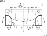
- the heat source device according to the fourth embodiment is different from heat source device 1 according to the first embodiment in that when seen from second direction Z, both ends 90bb and 90bc of windward end 90b of third wall portion 9w in first direction X are arranged on the windward side relative to a central portion 90ba of windward end 90b in first direction X.
- FIG. 9 fan 3, motor 11, support portion 12, compressor 201, and controller 205 are not shown.
- wiring portion 206 is not shown.
- windward end 4b of bell mouth 4, and a portion of windward end 90b of third wall portion 9w located on the leeward side relative to an end surface shown in Fig. 10 are indicated by a dotted line.
- windward end 90b of third wall portion 9w is provided to have a concave shape.
- windward end 90b includes central portion 90ba arranged to overlap with rotation axis O of fan 3 in second direction Z, end 90bb closest to first wall portion 7w, and end 90bc closest to second wall portion 8w.
- Central portion 90ba is arranged on the leeward side relative to both ends 90bb and 90bc in third direction Y.
- central portion 90ba is arranged on the leeward side relative to an imaginary straight line connecting both ends 90bb and 90bc to each other.
- the imaginary straight line is indicated by a dotted line in Fig. 9 .
- First surface portion 90 is provided in parallel with rotation axis O of fan 3.
- Second surface portion 91 is provided in parallel with, for example, the XZ plane extending along first direction X and second direction Z.
- An angle formed by first surface portion 90 and second surface portion 91 with respect to windward end 90b is, for example, 90 degrees.
- Windward end 90b of first surface portion 90 and second surface portion 91 are located on the windward side relative to bell mouth 4 and form a windward end of third wall portion 9w.
- Second surface portion 91 is arranged on the leeward side relative to heat source side heat exchanger 5.
- a lower end of second surface portion 91 is connected to bottom surface plate 2c.
- first wall portion 7w includes, for example, a fifth surface portion 70 and a sixth surface portion 71 arranged on the windward side relative to fifth surface portion 70.
- Fifth surface portion 70 is provided in parallel with rotation axis O of fan 3.
- Fifth surface portion 70 is provided in parallel with the YZ plane extending along second direction Z and third direction Y.
- Sixth surface portion 71 extends in a direction that intersects fifth surface portion 70.
- a windward end of fifth surface portion 70 is connected to a leeward end of sixth surface portion 71.
- a distance in first direction X between a windward end of sixth surface portion 71 of first wall portion 7w and rotation axis O is longer than a distance in first direction X between the leeward end of sixth surface portion 71 of first wall portion 7w and rotation axis O.
- second wall portion 8w includes, for example, a seventh surface portion 80 and an eighth surface portion 81 arranged on the windward side relative to seventh surface portion 80.
- Seventh surface portion 80 is provided in parallel with rotation axis O of fan 3.
- Seventh surface portion 80 is provided in parallel with the YZ plane extending along second direction Z and third direction Y.
- Eighth surface portion 81 extends in a direction that intersects seventh surface portion 80.
- a windward end of seventh surface portion 80 is connected to a leeward end of eighth surface portion 81.
- a distance in first direction X between a windward end of eighth surface portion 81 of second wall portion 8w and rotation axis O is longer than a distance in first direction X between the leeward end of eighth surface portion 81 of second wall portion 8w and rotation axis O.
- first wall portion 7W is preferably provided to include sixth surface portion 71 provided to connect to windward end 90b of third wall portion 9w.
- second wall portion 8W is preferably provided to include eighth surface portion 81 provided to connect to windward end 90b of third wall portion 9w.
- the windward end of fifth surface portion 70, sixth surface portion 71, the windward end of seventh surface portion 80, and eighth surface portion 81 are preferably provided to connect to windward end 90b of first surface portion 90 of third wall portion 9w in a curved surface shape.
- the windward end of fifth surface portion 70 is arranged to overlap with end 90bb of windward end 90b of first surface portion 90.
- the windward end of seventh surface portion 80 is arranged to overlap with end 90bc of windward end 90b of first surface portion 90.
- Fig. 10 is an end view, when seen from the windward side, of an end surface that passes through an intermediate portion 90bd located between central portion 90ba and end 90bb shown in Fig. 9 and an intermediate portion 90be located between central portion 90ba and end 90bc, and is perpendicular to third direction Y.
- a lower region of windward end 4b of bell mouth 4 including a portion located below rotation axis O and overlapping with rotation axis O in second direction Z is arranged to face bottom surface plate 2c in a radial direction of fan 3.
- a region of windward end 4b adjacent to the above-described lower region in first direction X is arranged to face first surface portion 90 in the above-described radial direction.
- a distance L5 in the above-described radial direction between the above-described lower region of windward end 4b of bell mouth 4 and bottom surface plate 2c is longer than a distance in the above-described radial direction between windward end 4b and central portion 90ba of windward end 90b.
- Above-described distance L5 is, for example, equal to or longer than a distance L6 in the above-described radial direction between windward end 4b of bell mouth 4 and intermediate portion 90bd of windward end 90b, and a distance in the above-described radial direction between windward end 4b and intermediate portion 90be.
- central portion 90ba of windward end 90b of first surface portion 90 is arranged on the leeward side relative to both ends 90bb and 90bc, and thus, above-described distance L5 may be equal to or longer than above-described distance L6.
- third wall portion 9w is arranged in a region where a distance in second direction Z between windward end 4b of bell mouth 4 and bottom surface plate 2c is relatively long in blower chamber 6. Therefore, in heat source device 1 according to the fourth embodiment, a difference between a maximum value and a minimum value of a distance in second direction Z between first surface portion 90 of third wall portion 9w and windward end 4b of bell mouth 4, and a rate of change in the above-described distance to a change in position in first direction X in the above-described region are smaller than those of heat source device 1 according to the first embodiment. As a result, in heat source device 1 according to the fourth embodiment, disturbance of the air flow in the above-described region of blower chamber 6 is reduced, as compared with heat source device 1 according to the first embodiment.
- windward end 90b of third wall portion 9w is provided to connect to the windward end of first wall portion 7w and the windward end of second wall portion 8w in an arc shape. Therefore, retention of the air is suppressed around a connecting portion that connects the windward end of first wall portion 7w and windward end 90b of third wall portion 9w to each other, i.e., around end 90bb, and around a connecting portion that connects the windward end of second wall portion 8w and windward end 90b of third wall portion 9w to each other, i.e., around end 90bc.
- first surface portion 90 may be provided to be inclined with respect to third direction Y, similarly to heat source device 1 according to the second embodiment.
- first surface portion 90 may include a plurality of inclined portions in a cross section perpendicular to first direction X, similarly to the heat source device according to the third embodiment.
- first surface portion 90 may include, for example, a first inclined portion 96 inclined with respect to above-described XY plane OS including rotation axis O, and a first parallel portion 97 parallel to above-described XY plane OS including rotation axis O.
- a windward end of first inclined portion 96 forms windward end 90b of first surface portion 90 and is connected to an upper end of second surface portion 91.
- a leeward end 96a of first inclined portion 96 is connected to a windward end of first parallel portion 97.
- a leeward end of first parallel portion 97 is connected to front surface plate 2a.
- the above-described windward portion of third wall portion 9w is formed by, for example, the whole of first inclined portion 92 and the whole of second surface portion 91.
- Fig. 12 fan 3, motor 11, support portion 12, compressor 201, and controller 205 are not shown.
- Fig. 13 wiring portion 206 is not shown.
- windward end 4b of bell mouth 4, and a portion of windward end 90b of third wall portion 9w located on the leeward wide relative to an end surface shown in Fig. 13 are indicated by a dotted line.
- Fig. 12 when seen from second direction Z, leeward end 96a of first inclined portion 96 is provided in parallel with, for example, windward end 90b of first surface portion 90.
- Fig. 13 is an end view when seen from an arrow XIII-XIII in Fig. 12 .
- P1 represents a portion that overlaps with rotation axis O in first inclined portion 96
- P2 represents leeward end 96a located on the second wall portion 8w side
- P3 represents an end of third wall portion 9w located on the second wall portion 8w side.
- windward end 90b of third wall portion 9w is preferably provided to connect to first wall portion 7w and second wall portion 8w.
- a lower region of windward end 4b of bell mouth 4 including a portion located below rotation axis O and overlapping with rotation axis O in second direction Z is arranged to face first inclined portion 92 in the above-described radial direction.
- a region of windward end 4b adjacent to the above-described lower region in first direction X is arranged to face first parallel portion 93 in the above-described radial direction.
- a distance L7 in the above-described radial direction between the above-described lower region of windward end 4b of bell mouth 4 and above-described P1 is longer than a distance in the above-described radial direction between windward end 4b and first parallel portion 97.
- Above-described distance L7 is, for example, equal to a distance between windward end 4b of bell mouth 4 and above-described P2.
- first inclined portion 96 is provided in parallel with, for example, windward end 4b of bell mouth 4.
- Above-described distance L7 is, for example, shorter than a distance L8 between windward end 4b of bell mouth 4 and above-described P3.
- the heat source device shown in Figs. 11 to 13 as described above is configured similarly to the heat source device according to the fourth embodiment and further includes first surface portion 90 similar to that of the heat source device according to the second embodiment. Therefore, the heat source device shown in Figs. 11 to 13 can simultaneously produce the effects of heat source devices 1 according to the second and fourth embodiments.
- heat source device 1 according to a fifth embodiment is configured basically similarly to heat source device 1 according to the first embodiment.
- heat source device 1 according to the fifth embodiment is different from heat source device 1 according to the first embodiment in that when seen from third direction Y, both ends of the above-described windward portion of third wall portion 9w in first direction X are arranged on the above-described XY plane side including rotation axis O relative to a central portion of the above-described windward portion in first direction X.
- First surface portion 90 of third wall portion 9w includes, for example, a first inclined portion 98 inclined with respect to above-described XY plane OS including rotation axis O, and a first parallel portion 99 parallel to above-described XY plane OS including rotation axis O.
- a windward end of first inclined portion 98 forms windward end 90b of first surface portion 90.
- a leeward end 98a of first inclined portion 98 is connected to a windward end of first parallel portion 99.
- the above-described windward portion is formed by, for example, the whole of first inclined portion 98.
- Leeward end 98a includes a central portion 98aa and both ends 98ab and 98ac in first direction X.
- both ends 98ab and 98ac are arranged on the above-described XY plane OS side including rotation axis O relative to central portion 98aa.
- a distance L9 in second direction Z between central portion 98aa and above-described XY plane OS is longer than a distance L10 in second direction Z between end 98ab and above-described XY plane OS, and a distance in second direction Z between end 98ac and above-described XY plane OS.
- Windward end 90b of first surface portion 90 includes central portion 90ba and both ends 90bb and 90bc in first direction X.
- both ends 90bb and 90bc are, for example, arranged on the above-described XY plane OS side including rotation axis O relative to central portion 90ba.
- a distance L11 in second direction Z between central portion 90ba and above-described XY plane OS is longer than a distance L12 in second direction Z between end 90bb and above-described XY plane OS, and a distance in second direction Z between end 90bc and above-described XY plane OS.
- Above-described distance L9 is shorter than above-described distance L11, and is longer than, for example, above-described distance L12.
- Above-described distance L10 is shorter than above-described distance L12.
- First inclined portion 98 is, for example, provided to form a conical surface having rotation axis O as a central axis and having a vertex arranged on the leeward side relative to fan 3.
- First parallel portion 99 is, for example, provided to form a cylindrical pillar surface having rotation axis O as a central axis.
- heat source device 1 according to the fifth embodiment when seen from third direction Y, both ends of the above-described windward portion of third wall portion 9w in first direction X are arranged on the above-described XY plane side including rotation axis O relative to the central portion of the above-described windward portion in first direction X. Therefore, in heat source device 1 according to the fifth embodiment, a distance between third wall portion 9w and windward end 4b in the vicinity of windward end 4b of bell mouth 4 is shorter and an amount of change in the distance in a circumferential direction of fan 3 is smaller than those in heat source devices 1 according to the first to fourth embodiments. As a result, in heat source device 1 according to the fifth embodiment, power consumption during air blowing is further reduced and noise is further reduced, as compared with heat source device 1 according to the second embodiment.
- first surface portion 90 includes first inclined portion 98 provided to be inclined with respect to third direction Y, similarly to heat source device 1 according to the second embodiment.
- First surface portion 90 may include only first parallel portion 99.
- first surface portion 90 may include a plurality of inclined portions in a cross section perpendicular to first direction X, similarly to the heat source device according to the third embodiment.
- Each inclined portion is, for example, provided to form a conical surface having rotation axis O as a central axis and having a vertex arranged on the leeward side relative to fan 3.
- First surface portion 90 may include a plurality of plane portions. Each plane portion is, for example, provided to form a cylindrical pillar surface having rotation axis O as a central axis.
- heat source device 1 according to a sixth embodiment is configured basically similarly to heat source device 1 according to the first embodiment.
- heat source device 1 according to the sixth embodiment is different from heat source device 1 according to the first embodiment in that second surface portion 91 is provided to be inclined with respect to the XZ plane.
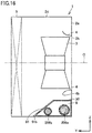
- Second surface portion 91 includes a leeward end 91a connected to a windward end of first surface portion 90, and a windward end 91b connected to bottom surface plate 2c. Windward end 91b of second surface portion 91 is arranged on the windward side relative to leeward end 91a of second surface portion 91. That is, windward end 91b of second surface portion 91 forms a windward end of third wall portion 9w.
- a distance in second direction Z between windward end 91b of second surface portion 91 and the above-described XY plane including rotation axis O is longer than a distance in second direction Z between leeward end 91a of second surface portion 91 and the above-described XY plane including rotation axis O.
- An angle formed by first surface portion 90 and second surface portion 91 with respect to windward end 90b is greater than 90 degrees.
- heat source device 1 according to the sixth embodiment an air flow in blower chamber 6 is guided by third wall portion 9w to reach windward end 4b of bell mouth 4, similarly to heat source device 1 according to the second embodiment. Therefore, heat source device 1 according to the sixth embodiment can produce an effect similar to that of heat source device 1 according to the second embodiment.
- Heat source device 1 according to the sixth embodiment may be configured similarly to the heat source device according to each of the second to fifth embodiments, except that second surface portion 91 is provided to be inclined with respect to the XZ plane.
- second surface portion 91 of the heat source device according to each of the second to fifth embodiments may be provided to be inclined with respect to the XZ plane.
- heat source device 1 according to a seventh embodiment is configured basically similarly to heat source device 1 according to the first embodiment.
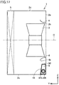
- heat source device 1 according to the seventh embodiment is different from heat source device 1 according to the first embodiment in that third wall portion 9w as a whole is arranged on the leeward side relative to bell mouth 4 in third direction Y. That is, third wall portion 9w in the seventh embodiment does not include the above-described windward portion.
- wiring portion 206 is housed in third mechanical chamber 9 partitioned from blower chamber 6 by third wall portion 9w. Therefore, the risk of the occurrence of an abnormality such as electric leakage and corrosion in wiring portion 206 is reduced.
- Second surface portion 91 of third wall portion 9w is preferably provided to be inclined with respect to the XZ plane.
- a speed of an air flow flowing through an outer peripheral region of blower chamber 6 located on the outer side of windward end 4b of bell mouth 4 relative to rotation axis O is higher than a speed of an air flow flowing through a central region of blower chamber 6 located on the inner side of windward end 4b of bell mouth 4 relative to rotation axis O. Therefore, an air passage resistance in blower chamber 6 becomes a problem in the above-described outer peripheral region.
- second surface portion 91 is provided to be inclined with respect to the XZ plane, an air flow along bottom surface plate 2c is guided by second surface portion 91 to reach windward end 4b of bell mouth 4. In this case, the occurrence of a vortex caused by separation of the air flow at second surface portion 91 is suppressed and an energy loss caused by the vortex is reduced.
- Third mechanical chamber 9, third wall portion 9w and wiring portion 206 of heat source device 1 according to each of the first to seventh embodiments may be arranged above fan 3.
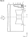
- Fig. 18 shows a configuration example in which third mechanical chamber 9, third wall portion 9w and wiring portion 206 in the second embodiment are arranged above fan 3.
- third mechanical chamber 9, third wall portion 9w and wiring portion 206 that are arranged above fan 3 may only be configured to be symmetrical with third mechanical chamber 9, third wall portion 9w and wiring portion 206 that are arranged below fan 3 shown in Figs. 1 to 17 with respect to rotation axis O.
- heat source side components housed in first mechanical chamber 7, second mechanical chamber 8 and third mechanical chamber 9 are not limited to compressor 201, heat source side heat exchanger 5, decompressing unit 203, four-way valve 204, controller 205, and wiring portion 206.
- refrigeration cycle apparatus 200 according to each of the first to seventh embodiments is not limited to the configuration shown in Fig. 1 .
- the refrigeration cycle apparatus may be configured as a so-called indirect air conditioner, or may be configured as a water heater.
- the above-described refrigeration cycle apparatus includes the above-described refrigerant circuit, a heat medium circuit through which a heat medium flows, and a heat exchanger configured to perform heat exchange between refrigerant flowing through the above-described refrigerant circuit and the heat medium flowing through the above-described heat medium circuit.
- the heat medium is, for example, water.
- the heat exchanger configured to perform heat exchange between the refrigerant and the heat medium is, for example, a plate-type heat exchanger.
- heat source device 1 according to each of the first to seventh embodiments further includes a plate-type heat exchanger in addition to heat source side heat exchanger 5, and the plate-type heat exchanger is housed in, for example, second mechanical chamber 8.
- Fig. 19 shows a configuration example in which a plate-type heat exchanger 210 is housed in second mechanical chamber 8 in the first embodiment.
- a refrigerant pipe 211 extending to plate-type heat exchanger 210 is passed through third mechanical chamber 9, together with wiring portion 206.
- An outer diameter of refrigerant pipe 211 is, for example, larger than an outer diameter of wiring portion 206.
- wiring portion 206 is arranged on the relatively windward side and refrigerant pipe 211 is arranged on the relatively leeward side.
- decompressing unit 203, four-way valve 204, and the refrigerant pipes other than refrigerant pipe 211 are not shown.
- third wall portion 9w may be provided by molding one member, or may be provided by connecting a plurality of members.
- Third wall portion 9w may be, for example, configured as a part of a cylindrical member as long as third wall portion 9w includes the above-described configuration. That is, third wall portion 9w may be provided to surround the entire perimeter of third mechanical chamber 9 in a cross section perpendicular to first direction X.
- Such a cylindrical member includes, in a circumferential direction thereof, a third surface portion connected to first surface portion 90 of third wall portion 9w, and a fourth surface portion connected to second surface portion 91 and the third surface portion.
- the above-described third surface portion is connected to front surface plate 2a, and the above-described fourth surface portion is connected to bottom surface plate 2c.
- third wall portion 9w may be configured as an eaves-shaped member not including the above-described third surface portion and the above-described fourth surface portion and including only first surface portion 90 and second surface portion 91.
- a gap may be provided between third wall portion 9w and first and second wall portions 7w and 8w.
Landscapes
- Engineering & Computer Science (AREA)
- Chemical & Material Sciences (AREA)
- Combustion & Propulsion (AREA)
- Mechanical Engineering (AREA)
- General Engineering & Computer Science (AREA)
- Other Air-Conditioning Systems (AREA)
- Detail Structures Of Washing Machines And Dryers (AREA)
Abstract
Description
- The present invention relates to a heat source device and a refrigeration cycle apparatus.
- There has been conventionally known a refrigeration cycle apparatus including: a heat source device (outdoor unit) housing a compressor, a heat source side heat exchanger, a blower configured to blow air into the heat source side heat exchanger, a driving unit configured to drive the compressor, and the like; and a load unit (indoor unit) housing a load side heat exchanger and a blower configured to blow air into the load side heat exchanger.
-
Japanese Patent Laying-Open No. 4-177031 - PTL 1:
Japanese Patent Laying-Open No. 4-177031 - As described above, in the heat source device in which the two mechanical chambers are provided to sandwich the blower chamber, an optional connecting member such as an electric wiring extends in the blower chamber, in addition to the refrigerant pipe, depending on a member housed in each mechanical chamber. Since the above-described blower chamber is connected to the outside of the outer case through the inlet and the outlet, the above-described connecting member is exposed to water, dust and the like taken into the above-described blower chamber from outside the outer case. As a result, there is a risk of the occurrence of an abnormality such as electric leakage and corrosion in the connecting member extending in the above-described blower chamber.
- A main object of the present invention is to provide a heat source device having a reduced risk of the occurrence of an abnormality such as electric leakage and corrosion in a connecting member extending in a blower chamber, as compared with a conventional heat source device.
- A heat source device according to the present invention is a heat source device which houses a plurality of heat source side components and a blower, the heat source device including: a blower chamber housing at least the blower; a first mechanical chamber housing a first member of the heat source side components; a second mechanical chamber housing a second member of the heat source side components; and a third mechanical chamber housing a connecting member connecting the first member and the second member to each other. The first mechanical chamber and the second mechanical chamber are arranged to sandwich the blower chamber in a first direction orthogonal to a rotation axis of the blower. The third mechanical chamber is arranged between the first mechanical chamber and the second mechanical chamber in the first direction, and arranged alongside the blower in a second direction orthogonal to each of the rotation axis and the first direction.
- According to the present invention, there can be provided a heat source device having a reduced risk of the occurrence of an abnormality such as electric leakage and corrosion in a connecting member extending in a blower chamber, as compared with a conventional heat source device.
-
-
Fig. 1 shows a refrigeration cycle apparatus according to a first embodiment. -
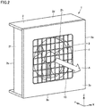
Fig. 2 is a perspective view showing a heat source device according to the first embodiment. -
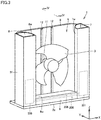
Fig. 3 is a perspective view showing the interior of an outer case of the heat source device shown inFig. 2 . -
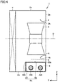
Fig. 4 is an end view when seen from an arrow IV-IV inFig. 3 . -
Fig. 5 is an end view of a heat source device according to a second embodiment. -
Fig. 6 is a perspective view showing the interior of an outer case of the heat source device shown inFig. 5 . -
Fig. 7 is an end view of a heat source device according to a third embodiment. -
Fig. 8 is a perspective view showing the interior of an outer case of a heat source device according to a fourth embodiment. -
Fig. 9 is an end view showing a third wall portion of the heat source device shown inFig. 8 . -
Fig. 10 is an end view when seen from an arrow X-X inFig. 9 . -
Fig. 11 is a perspective view showing a modification of the heat source device according to the fourth embodiment. -
Fig. 12 is an end view showing a third wall portion of the heat source device shown inFig. 11 . -
Fig. 13 is an end view when seen from an arrow XIII-XIII inFig. 12 . -
Fig. 14 is a perspective view showing the interior of an outer case of a heat source device according to a fifth embodiment. -
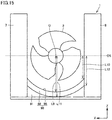
Fig. 15 is a plan view of the heat source device shown inFig. 14 , when seen from the inlet side. -
Fig. 16 is an end view of a heat source device according to a sixth embodiment. -
Fig. 17 is an end view of a heat source device according to a seventh embodiment. -
Fig. 18 is an end view showing a modification of the heat source device according to the second embodiment. -
Fig. 19 is a perspective view showing a modification of the heat source device according to the first embodiment. - Embodiments of the present invention will be described hereinafter with reference to the drawings. In the following description, for convenience in description, a first direction X, a second direction Z and a third direction Y that are orthogonal to each other will be used.
- First, a
refrigeration cycle apparatus 200 according to a first embodiment will be described with reference toFig. 1 .Refrigeration cycle apparatus 200 includes a refrigerant circuit through which refrigerant circulates. The above-described refrigerant circuit includes acompressor 201, a heat sourceside heat exchanger 5, a loadside heat exchanger 202, adecompressing unit 203, and a four-way valve 204.Refrigeration cycle apparatus 200 further includes acontroller 205 and awiring portion 206 as control members for controllingcompressor 201. -
Compressor 201 is, for example, an inverter compressor whose rotation speed is inverter-controlled. Heat sourceside heat exchanger 5 and loadside heat exchanger 202 are provided to perform heat exchange between the refrigerant and the air.Decompressing unit 203 is, for example, an electronic expansion valve whose degree of opening is adjustable. Four-way valve 204 is provided to switch a state between a first state in which heat sourceside heat exchanger 5 functions as a condenser and loadside heat exchanger 202 functions as an evaporator and a second state in which heat sourceside heat exchanger 5 functions as an evaporator and loadside heat exchanger 202 functions as a condenser.Controller 205 controls driving ofcompressor 201.Controller 205 is connected tocompressor 201 bywiring portion 206 serving as a connecting member.Wiring portion 206 transmits electric power and an operation signal fromcontroller 205 tocompressor 201.Wiring portion 206 includes a plurality ofwirings -
Compressor 201, heat sourceside heat exchanger 5,decompressing unit 203, four-way valve 204,controller 205, andwiring portion 206 ofrefrigeration cycle apparatus 200 are housed in aheat source device 1. Herein,compressor 201, heat sourceside heat exchanger 5,decompressing unit 203, four-way valve 204,controller 205, andwiring portion 206 will be referred to as heat source side components ofrefrigeration cycle apparatus 200.Heat source device 1 is arranged, for example, outside a room. Loadside heat exchanger 202 is housed in anindoor unit 207.Indoor unit 207 is arranged inside a room.Heat source device 1 andindoor unit 207 are connected to each other byrefrigerant pipes - As shown in
Figs. 2 and4 ,heat source device 1 includes anouter case 2.Outer case 2 forms an outer profile ofheat source device 1 and the components housed inheat source device 1 are arranged inouter case 2. As shown inFigs. 1 ,3 and4 ,heat source device 1 further includes afan 3, abell mouth 4, heat sourceside heat exchanger 5, amotor 11, asupport portion 12, afirst wall portion 7w, asecond wall portion 8w, athird wall portion 9w,compressor 201, decompressingunit 203, four-way valve 204, andcontroller 205 that are arranged insideouter case 2, and afan guard 13 that is arranged outsideouter case 2. Second direction Z corresponds to a vertical direction. First direction X and third direction Y correspond to, for example, a horizontal direction. InFig. 3 , decompressingunit 203, four-way valve 204, and the refrigerant pipes that form a part of the above-described refrigerant circuit are not shown. - As shown in
Fig. 2 ,outer case 2 includes afront surface plate 2a and arear surface plate 2b that extend along first direction X and second direction Z and are spaced apart from each other in third direction Y.Outer case 2 further includes abottom surface plate 2c and atop surface plate 2d that extend along first direction X and third direction Y and are spaced apart from each other in second direction Z.Outer case 2 further includesside surface plates - As shown in
Fig. 2 ,front surface plate 2a is provided with anoutlet 2h.Rear surface plate 2b is provided with a not-shown inlet. An opening area of the inlet is larger than an opening area ofoutlet 2h. A lower end of the inlet is, for example, arranged below a lower end ofoutlet 2h. An upper end of the inlet is, for example, arranged above an upper end ofoutlet 2h. Centers of the inlet andoutlet 2h are, for example, arranged on a rotation axis O offan 3 so as tosandwich fan 3. Whenfan 3 rotates, an air flow A (seeFig. 2 ) along third direction Y is blown out fromoutlet 2h. Hereinafter, as to a relative positional relationship in third direction Y between a plurality of components, the inlet side will be referred to as the windward side, and the outlet side will be referred to as the leeward side. - As shown in
Figs. 3 and4 ,fan 3 is provided to rotate about the rotation axis extending along third direction Y.Fan 3 is driven bymotor 11.Fan 3 andmotor 11 are supported bysupport portion 12.Support portion 12 is fixed to, for example,bottom surface plate 2c andtop surface plate 2d ofouter case 2.Fan 3,motor 11 andsupport portion 12 form a blower and are, for example, arranged on the leeward side relative to heat sourceside heat exchanger 5. - As shown in
Fig. 4 ,bell mouth 4 is arranged to connect tooutlet 2h ofouter case 2.Bell mouth 4 is arranged to surround a portion offan 3 located on the leeward side.Bell mouth 4 includes aleeward end 4a connected tofront surface plate 2a ofouter case 2, and awindward end 4b arranged on the inlet side relative toleeward end 4a.Windward end 4b is arranged on the leeward side relative to a windward end offan 3 and on the windward side relative to a leeward end offan 3. - As shown in
Fig. 1 ,fan guard 13 is arranged on the outer side offront surface plate 2a so as to overlap withoutlet 2h in third direction Y. - Heat source
side heat exchanger 5 is provided to perform heat exchange between the air suctioned from the outside ofheat source device 1 to the inside ofheat source device 1 byfan 3 and the refrigerant circulating through the refrigerant circuit of above-describedrefrigeration cycle apparatus 200. Heat sourceside heat exchanger 5 is arranged to be in contact with, for example,rear surface plate 2b,bottom surface plate 2c,top surface plate 2d, andside surface plates side heat exchanger 5 is arranged on the windward side relative tofan 3,bell mouth 4,motor 11, andsupport portion 12. - As shown in
Fig. 3 , withinouter case 2,first wall portion 7w,second wall portion 8w andthird wall portion 9w serve as partitions between ablower chamber 6 and a firstmechanical chamber 7, a secondmechanical chamber 8 and a thirdmechanical chamber 9, respectively.First wall portion 7w serves as a partition betweenblower chamber 6 and firstmechanical chamber 7.Second wall portion 8w serves as a partition betweenblower chamber 6 and secondmechanical chamber 8.Third wall portion 9w serves as a partition betweenblower chamber 6 and thirdmechanical chamber 9. -
First wall portion 7w is provided such that firstmechanical chamber 7 partitioned fromblower chamber 6 and extending along second direction Z is formed on theside surface plate 2e side relative tofan 3 in first direction X. When seen from second direction Z,first wall portion 7w is provided to have, for example, a substantially arc shape. A length offirst wall portion 7w in second direction Z is equal to or longer than a length offan 3 in second direction Z, i.e., an outer diameter offan 3. A distance betweenfirst wall portion 7w and a YZ plane including rotation axis O offan 3 and extending along second direction Z and third direction Y is, for example, constant. Preferably, a distance between a windward end offirst wall portion 7w and the above-described YZ plane including rotation axis O is longer than a distance between a leeward end offirst wall portion 7w and the above-described YZ plane including rotation axis O. More preferably, the distance betweenfirst wall portion 7w and the above-described YZ plane including rotation axis O becomes shorter from the windward side toward the leeward side in third direction Y. The distance betweenfirst wall portion 7w and the above-described YZ plane including rotation axis O offan 3 is longer than a distance betweenwindward end 4b ofbell mouth 4 and the above-described YZ plane. -
Second wall portion 8w is provided such that secondmechanical chamber 8 partitioned fromblower chamber 6 and extending along second direction Z is formed on theside surface plate 2f side relative tofan 3 in first direction X. When seen from third direction Y,second wall portion 8w is provided to have, for example, a substantially arc shape.First wall portion 7w andsecond wall portion 8w are symmetrical with respect to rotation axis O. A length ofsecond wall portion 8w in second direction Z is equal to or longer than the length offan 3 in second direction Z, i.e., the outer diameter offan 3. A distance betweensecond wall portion 8w and the above-described YZ plane is, for example, constant. Preferably, a distance between a windward end ofsecond wall portion 8w and the above-described YZ plane including rotation axis O is longer than a distance between a leeward end ofsecond wall portion 8w and the above-described YZ plane including rotation axis O. More preferably, the distance betweensecond wall portion 8w and the above-described YZ plane including rotation axis O becomes shorter from the windward side toward the leeward side in third direction Y. The distance betweensecond wall portion 8w and the above-described YZ plane including rotation axis O offan 3 is longer than the distance betweenwindward end 4b ofbell mouth 4 and the above-described YZ plane. - As shown in
Figs. 3 and4 ,third wall portion 9w is provided such that thirdmechanical chamber 9 partitioned fromblower chamber 6 and extending along first direction X is formed on thebottom surface plate 2c side relative tofan 3 in third direction Y.Third wall portion 9w is connected to, for example,first wall portion 7w,second wall portion 8w,front surface plate 2a, andbottom surface plate 2c. A length ofthird wall portion 9w in first direction X is equal to or longer than a length offan 3 in first direction X, i.e., the outer diameter offan 3. -
Third wall portion 9w includes afirst surface portion 90 and asecond surface portion 91 extending in a direction that intersectsfirst surface portion 90.First surface portion 90 andsecond surface portion 91 are connected to, for example,first wall portion 7w andsecond wall portion 8w. A part offirst surface portion 90 located on the windward side and the whole ofsecond surface portion 91 form a windward portion ofthird wall portion 9w located on the windward side relative towindward end 4b ofbell mouth 4. -
First surface portion 90 is provided in parallel with rotation axis O offan 3. From a different perspective,first surface portion 90 is provided in parallel with an XY plane extending along first direction X and third direction Y.First surface portion 90 includes aleeward end 90a and awindward end 90b.Leeward end 90a is connected tofront surface plate 2a.Windward end 90b is connected to an upper end ofsecond surface portion 91. -
Second surface portion 91 is provided in parallel with, for example, an XZ plane extending along first direction X and second direction Z. An angle formed byfirst surface portion 90 andsecond surface portion 91 with respect towindward end 90b is, for example, 90 degrees.Windward end 90b offirst surface portion 90 andsecond surface portion 91 are located on the windward side relative tobell mouth 4 and form a windward end ofthird wall portion 9w.Second surface portion 91 is arranged on the leeward side relative to heat sourceside heat exchanger 5. A lower end ofsecond surface portion 91 is connected tobottom surface plate 2c. - A distance in second direction Z between
third wall portion 9w and the above-described XY plane including rotation axis O offan 3 is, for example, constant. In other words, a distance in second direction Z between a windward end ofthird wall portion 9w and the above-described XY plane including rotation axis O offan 3, i.e., a distance in second direction Z betweenwindward end 90b and the above-described XY plane including rotation axis O offan 3 is equal to a distance in second direction Z between a leeward portion offirst surface portion 90 located on the leeward side relative towindward end 90b and the above-described XY plane. A distance in second direction Z between the above-described leeward portion offirst surface portion 90 and the above-described XY plane including rotation axis O is longer than a distance in second direction Z betweenwindward end 4b ofbell mouth 4 and the above-described XY plane including rotation axis O. - Within
outer case 2,heat source device 1 includesblower chamber 6, and firstmechanical chamber 7, secondmechanical chamber 8 and thirdmechanical chamber 9 that are partitioned fromblower chamber 6 byfirst wall portion 7w,second wall portion 8w andthird wall portion 9w, respectively. -
Blower chamber 6 facesfront surface plate 2a,rear surface plate 2b,top surface plate 2d,first wall portion 7w,second wall portion 8w, andthird wall portion 9w. - First
mechanical chamber 7 facesfront surface plate 2a,bottom surface plate 2c,top surface plate 2d,side surface plate 2e, andfirst wall portion 7w. Secondmechanical chamber 8 facesfront surface plate 2a,bottom surface plate 2c,top surface plate 2d,side surface plate 2f, andsecond wall portion 8w. Thirdmechanical chamber 9 facesfront surface plate 2a,bottom surface plate 2c andthird wall portion 9w. - First
mechanical chamber 7 and secondmechanical chamber 8 are arranged tosandwich blower chamber 6 in first direction X. Firstmechanical chamber 7 and secondmechanical chamber 8 are, for example, arranged tosandwich fan 3 andbell mouth 4 in first direction X. Thirdmechanical chamber 9 connects firstmechanical chamber 7 and secondmechanical chamber 8 to each other, and is arranged alongsideblower chamber 6 in second direction Z. Thirdmechanical chamber 9 is, for example, arranged belowblower chamber 6, and includes one end connected to a lower end of firstmechanical chamber 7 and the other end connected to a lower end of secondmechanical chamber 8. Thirdmechanical chamber 9 is, for example, arranged belowfan 3 andbell mouth 4. -
Blower chamber 6 is connected to the outside ofouter case 2 through the inlet and the outlet.Fan 3,bell mouth 4, heat sourceside heat exchanger 5,motor 11, andsupport portion 12 are housed inblower chamber 6.Compressor 201, decompressingunit 203 and four-way valve 204 are housed in firstmechanical chamber 7.Controller 205 is housed in secondmechanical chamber 8.Wiring portion 206 is housed in thirdmechanical chamber 9. - Heat
source device 1 includesblower chamber 6 housing at least heat sourceside heat exchanger 5 andfan 3, firstmechanical chamber 7housing compressor 201 serving as a first member, secondmechanical chamber 8housing controller 205 serving as a second member, thirdmechanical chamber 9housing wiring portion 206 serving as a connectingmember connecting compressor 201 andcontroller 205 to each other,first wall portion 7w serving as a partition betweenblower chamber 6 and firstmechanical chamber 7,second wall portion 8w serving as a partition betweenblower chamber 6 and secondmechanical chamber 8, andthird wall portion 9w serving as a partition betweenblower chamber 6 and thirdmechanical chamber 9. Firstmechanical chamber 7 and secondmechanical chamber 8 are arranged tosandwich blower chamber 6 in first direction X orthogonal to rotation axis O offan 3. Thirdmechanical chamber 9 connects firstmechanical chamber 7 and secondmechanical chamber 8 to each other, and is arranged alongsidefan 3 in second direction Z orthogonal to each of rotation axis O and first direction X. - In
heat source device 1,wiring portion 206 is housed in thirdmechanical chamber 9 partitioned fromblower chamber 6 bythird wall portion 9w. Therefore, the risk of the occurrence of an abnormality such as electric leakage and corrosion inwiring portion 206 is reduced. - As shown in
Figs. 5 and6 ,heat source device 1 according to a second embodiment is configured basically similarly to heatsource device 1 according to the first embodiment. However,heat source device 1 according to the second embodiment is different fromheat source device 1 according to the first embodiment in that the above-described windward portion ofthird wall portion 9w is provided to be inclined with respect to third direction Y in a cross section perpendicular to first direction X. -
First surface portion 90 is provided to intersect the above-described XY plane including rotation axis O. An inclination offirst surface portion 90 with respect to the above-described XY plane including rotation axis O is constant.First surface portion 90 is provided to have a flat plate shape. The above-described windward portion is formed by a part offirst surface portion 90 includingwindward end 90b. - A distance L1 in second direction Z between above-described
windward end 90b ofthird wall portion 9w and the above-described XY plane including rotation axis O is longer than a distance L2 in second direction Z between the above-described leeward portion and the above-described XY plane including rotation axis O. From a different perspective, distance L1 in second direction Z between above-describedwindward end 90b ofthird wall portion 9w and rotation axis O is longer than distance L2 in second direction Z between the above-described leeward portion and rotation axis O. Above-described distance L2 is longer than a distance L3 in second direction Z betweenwindward end 4b ofbell mouth 4 and the above-described XY plane including rotation axis O. The distance betweenthird wall portion 9w and the above-described XY plane including rotation axis O becomes shorter from the windward side toward the leeward side in third direction Y. - In
heat source device 1 according to the second embodiment, an air flow inblower chamber 6 is guided bythird wall portion 9w to reachwindward end 4b ofbell mouth 4. Therefore, inheat source device 1 according to the second embodiment, the occurrence of a vortex caused by separation of the air flow atthird wall portion 9w is suppressed and an energy loss caused by the vortex is reduced, as compared withheat source device 1 according to the first embodiment. As a result, inheat source device 1 according to the second embodiment, power consumption during air blowing is reduced, and pressure fluctuations occurring at blades offan 3 are small, which leads to a reduction in noise, as compared withheat source device 1 according to the first embodiment. - A width in second direction Z of
wiring 206a located on the leeward side, ofwiring portion 206, may be equal to a width in second direction Z ofwiring 206b located on the windward side, or may be greater than the width in second direction Z ofwiring 206b. - As shown in
Fig. 7 , a heat source device according to a third embodiment is configured basically similarly to heatsource device 1 according to the second embodiment. However, the heat source device according to the third embodiment is different fromheat source device 1 according to the second embodiment in that in a cross section perpendicular to first direction X,first surface portion 90 includes a plurality of inclined portions inclined with respect to above-described XY plane OS including rotation axis O. - In the cross section perpendicular to first direction X,
first surface portion 90 includes, for example, the plurality of inclined portions inclined with respect to above-described XY plane OS, and at least one parallel portion parallel to above-described XY plane OS.First surface portion 90 includes, for example, a firstinclined portion 92, a firstparallel portion 93, a secondinclined portion 94, and a secondparallel portion 95 that are arranged side by side in third direction Y. The above-described windward portion ofthird wall portion 9w is formed by, for example, first inclinedportion 92, firstparallel portion 93 and secondinclined portion 94. - A windward end of first
inclined portion 92 forms windwardend 90b offirst surface portion 90 and is connected to an upper end ofsecond surface portion 91. A leeward end of firstinclined portion 92 is connected to a windward end of firstparallel portion 93. A leeward end of firstparallel portion 93 is connected to a windward end of secondinclined portion 94. A leeward end of secondinclined portion 94 is connected to a windward end of secondparallel portion 95. A leeward end of secondparallel portion 95 forms leewardend 90a offirst surface portion 90 and is connected tofront surface plate 2a. - A distance in second direction Z between first
inclined portion 92 and above-described XY plane OS, and a distance in second direction Z between secondinclined portion 94 and above-described XY plane OS become shorter from the windward side toward the leeward side. A distance in second direction Z between firstparallel portion 93 and above-described XY plane OS, and a distance in second direction Z between secondparallel portion 95 and above-described XY plane OS are constant. - A distance in second direction Z between above-described
windward end 90b ofthird wall portion 9w, i.e., the windward end of firstinclined portion 92 and above-described XY plane OS is longer than a distance L4 in second direction Z between firstparallel portion 93 located on the leeward side relative to firstinclined portion 92 and above-described XY plane OS. Above-described distance L4 is longer than a distance L5 in second direction Z between secondparallel portion 95 located on the leeward side relative to firstparallel portion 93 and above-described XY plane OS. - An inclination angle of first
inclined portion 92 with respect to above-described XY plane OS is, for example, smaller than an inclination angle of secondinclined portion 94 with respect to above-described XY plane OS. - Alternatively, in the cross section perpendicular to first direction X,
first surface portion 90 may, for example, include only the plurality of inclined portions inclined with respect to above-described XY plane OS, and the inclined portions may have different inclination angles with respect to above-described XY plane OS to achieve a staircase shape. An inclination angle of an inclined portion arranged on the relatively windward side is smaller than an inclination angle of an inclined portion arranged on the relatively leeward side. - In
heat source device 1 according to the third embodiment as well, an air flow inblower chamber 6 is guided bythird wall portion 9w to reachwindward end 4b ofbell mouth 4, similarly to heatsource device 1 according to the second embodiment. Therefore,heat source device 1 according to the third embodiment can produce an effect similar to that ofheat source device 1 according to the second embodiment. - As shown in
Figs. 8 to 10 , a heat source device according to a fourth embodiment is configured basically similarly to heatsource device 1 according to the first embodiment. However, the heat source device according to the fourth embodiment is different fromheat source device 1 according to the first embodiment in that when seen from second direction Z, both ends 90bb and 90bc ofwindward end 90b ofthird wall portion 9w in first direction X are arranged on the windward side relative to a central portion 90ba ofwindward end 90b in first direction X. - In
Fig. 9 ,fan 3,motor 11,support portion 12,compressor 201, andcontroller 205 are not shown. InFig. 10 ,wiring portion 206 is not shown. InFig. 10 ,windward end 4b ofbell mouth 4, and a portion ofwindward end 90b ofthird wall portion 9w located on the leeward side relative to an end surface shown inFig. 10 are indicated by a dotted line. - As shown in
Fig. 9 , when seen from second direction Z,windward end 90b ofthird wall portion 9w is provided to have a concave shape. When seen from second direction Z,windward end 90b includes central portion 90ba arranged to overlap with rotation axis O offan 3 in second direction Z, end 90bb closest tofirst wall portion 7w, and end 90bc closest tosecond wall portion 8w. Central portion 90ba is arranged on the leeward side relative to both ends 90bb and 90bc in third direction Y. In other words, central portion 90ba is arranged on the leeward side relative to an imaginary straight line connecting both ends 90bb and 90bc to each other. The imaginary straight line is indicated by a dotted line inFig. 9 .First surface portion 90 is provided in parallel with rotation axis O offan 3. -
Second surface portion 91 is provided in parallel with, for example, the XZ plane extending along first direction X and second direction Z. An angle formed byfirst surface portion 90 andsecond surface portion 91 with respect towindward end 90b is, for example, 90 degrees.Windward end 90b offirst surface portion 90 andsecond surface portion 91 are located on the windward side relative tobell mouth 4 and form a windward end ofthird wall portion 9w.Second surface portion 91 is arranged on the leeward side relative to heat sourceside heat exchanger 5. A lower end ofsecond surface portion 91 is connected tobottom surface plate 2c. - As shown in
Fig. 9 ,first wall portion 7w includes, for example, afifth surface portion 70 and asixth surface portion 71 arranged on the windward side relative tofifth surface portion 70.Fifth surface portion 70 is provided in parallel with rotation axis O offan 3.Fifth surface portion 70 is provided in parallel with the YZ plane extending along second direction Z and third direction Y.Sixth surface portion 71 extends in a direction that intersectsfifth surface portion 70. A windward end offifth surface portion 70 is connected to a leeward end ofsixth surface portion 71. A distance in first direction X between a windward end ofsixth surface portion 71 offirst wall portion 7w and rotation axis O is longer than a distance in first direction X between the leeward end ofsixth surface portion 71 offirst wall portion 7w and rotation axis O. - As shown in
Fig. 9 ,second wall portion 8w includes, for example, aseventh surface portion 80 and aneighth surface portion 81 arranged on the windward side relative toseventh surface portion 80.Seventh surface portion 80 is provided in parallel with rotation axis O offan 3.Seventh surface portion 80 is provided in parallel with the YZ plane extending along second direction Z and third direction Y.Eighth surface portion 81 extends in a direction that intersectsseventh surface portion 80. A windward end ofseventh surface portion 80 is connected to a leeward end ofeighth surface portion 81. A distance in first direction X between a windward end ofeighth surface portion 81 ofsecond wall portion 8w and rotation axis O is longer than a distance in first direction X between the leeward end ofeighth surface portion 81 ofsecond wall portion 8w and rotation axis O. - As shown in
Fig. 9 , when seen from second direction Z, first wall portion 7W is preferably provided to includesixth surface portion 71 provided to connect towindward end 90b ofthird wall portion 9w. When seen from second direction Z, second wall portion 8W is preferably provided to includeeighth surface portion 81 provided to connect towindward end 90b ofthird wall portion 9w. In other words, when seen from second direction Z, the windward end offifth surface portion 70,sixth surface portion 71, the windward end ofseventh surface portion 80, andeighth surface portion 81 are preferably provided to connect towindward end 90b offirst surface portion 90 ofthird wall portion 9w in a curved surface shape. When seen from second direction Z, the windward end offifth surface portion 70 is arranged to overlap with end 90bb ofwindward end 90b offirst surface portion 90. When seen from second direction Z, the windward end ofseventh surface portion 80 is arranged to overlap with end 90bc ofwindward end 90b offirst surface portion 90. -
Fig. 10 is an end view, when seen from the windward side, of an end surface that passes through an intermediate portion 90bd located between central portion 90ba and end 90bb shown inFig. 9 and an intermediate portion 90be located between central portion 90ba and end 90bc, and is perpendicular to third direction Y. - As shown in
Fig. 10 , a lower region ofwindward end 4b ofbell mouth 4 including a portion located below rotation axis O and overlapping with rotation axis O in second direction Z is arranged to facebottom surface plate 2c in a radial direction offan 3. A region ofwindward end 4b adjacent to the above-described lower region in first direction X is arranged to facefirst surface portion 90 in the above-described radial direction. - As shown in
Fig. 10 , a distance L5 in the above-described radial direction between the above-described lower region ofwindward end 4b ofbell mouth 4 andbottom surface plate 2c is longer than a distance in the above-described radial direction betweenwindward end 4b and central portion 90ba ofwindward end 90b. Above-described distance L5 is, for example, equal to or longer than a distance L6 in the above-described radial direction betweenwindward end 4b ofbell mouth 4 and intermediate portion 90bd ofwindward end 90b, and a distance in the above-described radial direction betweenwindward end 4b and intermediate portion 90be. - In
heat source device 1 according to the fourth embodiment, central portion 90ba ofwindward end 90b offirst surface portion 90 is arranged on the leeward side relative to both ends 90bb and 90bc, and thus, above-described distance L5 may be equal to or longer than above-described distance L6. This makes a speed of an air flow flowing over central portion 90ba lower than a speed of an air flow flowing over above-described intermediate portions 90bd and 90be, and thus, a pressure loss of the air flow flowing over central portion 90ba is reduced, as compared with a pressure loss of the air flow flowing over above-described intermediate portions 90bd and 90be. - Furthermore, as shown in
Fig. 10 , inheat source device 1 according to the fourth embodiment,third wall portion 9w is arranged in a region where a distance in second direction Z betweenwindward end 4b ofbell mouth 4 andbottom surface plate 2c is relatively long inblower chamber 6. Therefore, inheat source device 1 according to the fourth embodiment, a difference between a maximum value and a minimum value of a distance in second direction Z betweenfirst surface portion 90 ofthird wall portion 9w andwindward end 4b ofbell mouth 4, and a rate of change in the above-described distance to a change in position in first direction X in the above-described region are smaller than those ofheat source device 1 according to the first embodiment. As a result, inheat source device 1 according to the fourth embodiment, disturbance of the air flow in the above-described region ofblower chamber 6 is reduced, as compared withheat source device 1 according to the first embodiment. - In addition, in
heat source device 1 according to the fourth embodiment, when seen from second direction Z,windward end 90b ofthird wall portion 9w is provided to connect to the windward end offirst wall portion 7w and the windward end ofsecond wall portion 8w in an arc shape. Therefore, retention of the air is suppressed around a connecting portion that connects the windward end offirst wall portion 7w andwindward end 90b ofthird wall portion 9w to each other, i.e., around end 90bb, and around a connecting portion that connects the windward end ofsecond wall portion 8w andwindward end 90b ofthird wall portion 9w to each other, i.e., around end 90bc. - In the heat source device according to the fourth embodiment,
first surface portion 90 may be provided to be inclined with respect to third direction Y, similarly to heatsource device 1 according to the second embodiment. In addition, in the heat source device according to the fourth embodiment,first surface portion 90 may include a plurality of inclined portions in a cross section perpendicular to first direction X, similarly to the heat source device according to the third embodiment. - As shown in
Figs. 11 to 13 ,first surface portion 90 may include, for example, a firstinclined portion 96 inclined with respect to above-described XY plane OS including rotation axis O, and a firstparallel portion 97 parallel to above-described XY plane OS including rotation axis O. A windward end of firstinclined portion 96 forms windwardend 90b offirst surface portion 90 and is connected to an upper end ofsecond surface portion 91. Aleeward end 96a of firstinclined portion 96 is connected to a windward end of firstparallel portion 97. A leeward end of firstparallel portion 97 is connected tofront surface plate 2a. The above-described windward portion ofthird wall portion 9w is formed by, for example, the whole of firstinclined portion 92 and the whole ofsecond surface portion 91. - In
Fig. 12 ,fan 3,motor 11,support portion 12,compressor 201, andcontroller 205 are not shown. InFig. 13 ,wiring portion 206 is not shown. InFig. 13 ,windward end 4b ofbell mouth 4, and a portion ofwindward end 90b ofthird wall portion 9w located on the leeward wide relative to an end surface shown inFig. 13 are indicated by a dotted line. - As shown in
Fig. 12 , when seen from second direction Z,leeward end 96a of firstinclined portion 96 is provided in parallel with, for example,windward end 90b offirst surface portion 90.Fig. 13 is an end view when seen from an arrow XIII-XIII inFig. 12 . InFigs. 12 and13 , in the end surface shown inFig. 13 , P1 represents a portion that overlaps with rotation axis O in firstinclined portion 96, P2 representsleeward end 96a located on thesecond wall portion 8w side, and P3 represents an end ofthird wall portion 9w located on thesecond wall portion 8w side. - As shown in
Fig. 12 , when seen from second direction Z,windward end 90b ofthird wall portion 9w is preferably provided to connect tofirst wall portion 7w andsecond wall portion 8w. - As shown in
Fig. 13 , a lower region ofwindward end 4b ofbell mouth 4 including a portion located below rotation axis O and overlapping with rotation axis O in second direction Z is arranged to face first inclinedportion 92 in the above-described radial direction. A region ofwindward end 4b adjacent to the above-described lower region in first direction X is arranged to face firstparallel portion 93 in the above-described radial direction. - As shown in
Fig. 13 , a distance L7 in the above-described radial direction between the above-described lower region ofwindward end 4b ofbell mouth 4 and above-described P1 is longer than a distance in the above-described radial direction betweenwindward end 4b and firstparallel portion 97. Above-described distance L7 is, for example, equal to a distance betweenwindward end 4b ofbell mouth 4 and above-described P2. In the end surface shown inFig. 13 , first inclinedportion 96 is provided in parallel with, for example,windward end 4b ofbell mouth 4. Above-described distance L7 is, for example, shorter than a distance L8 betweenwindward end 4b ofbell mouth 4 and above-described P3. - The heat source device shown in
Figs. 11 to 13 as described above is configured similarly to the heat source device according to the fourth embodiment and further includesfirst surface portion 90 similar to that of the heat source device according to the second embodiment. Therefore, the heat source device shown inFigs. 11 to 13 can simultaneously produce the effects ofheat source devices 1 according to the second and fourth embodiments. - As shown in
Figs. 14 and15 ,heat source device 1 according to a fifth embodiment is configured basically similarly to heatsource device 1 according to the first embodiment. However,heat source device 1 according to the fifth embodiment is different fromheat source device 1 according to the first embodiment in that when seen from third direction Y, both ends of the above-described windward portion ofthird wall portion 9w in first direction X are arranged on the above-described XY plane side including rotation axis O relative to a central portion of the above-described windward portion in first direction X. -
First surface portion 90 ofthird wall portion 9w includes, for example, a firstinclined portion 98 inclined with respect to above-described XY plane OS including rotation axis O, and a firstparallel portion 99 parallel to above-described XY plane OS including rotation axis O. A windward end of firstinclined portion 98 forms windwardend 90b offirst surface portion 90. Aleeward end 98a of firstinclined portion 98 is connected to a windward end of firstparallel portion 99. The above-described windward portion is formed by, for example, the whole of firstinclined portion 98. -
Leeward end 98a includes a central portion 98aa and both ends 98ab and 98ac in first direction X. When seen from third direction Y, both ends 98ab and 98ac are arranged on the above-described XY plane OS side including rotation axis O relative to central portion 98aa. In other words, a distance L9 in second direction Z between central portion 98aa and above-described XY plane OS is longer than a distance L10 in second direction Z between end 98ab and above-described XY plane OS, and a distance in second direction Z between end 98ac and above-described XY plane OS. -
Windward end 90b offirst surface portion 90 includes central portion 90ba and both ends 90bb and 90bc in first direction X. When seen from third direction Y, both ends 90bb and 90bc are, for example, arranged on the above-described XY plane OS side including rotation axis O relative to central portion 90ba. In other words, a distance L11 in second direction Z between central portion 90ba and above-described XY plane OS is longer than a distance L12 in second direction Z between end 90bb and above-described XY plane OS, and a distance in second direction Z between end 90bc and above-described XY plane OS. - Above-described distance L9 is shorter than above-described distance L11, and is longer than, for example, above-described distance L12. Above-described distance L10 is shorter than above-described distance L12.
- First
inclined portion 98 is, for example, provided to form a conical surface having rotation axis O as a central axis and having a vertex arranged on the leeward side relative tofan 3. Firstparallel portion 99 is, for example, provided to form a cylindrical pillar surface having rotation axis O as a central axis. - In
heat source device 1 according to the fifth embodiment, when seen from third direction Y, both ends of the above-described windward portion ofthird wall portion 9w in first direction X are arranged on the above-described XY plane side including rotation axis O relative to the central portion of the above-described windward portion in first direction X. Therefore, inheat source device 1 according to the fifth embodiment, a distance betweenthird wall portion 9w andwindward end 4b in the vicinity ofwindward end 4b ofbell mouth 4 is shorter and an amount of change in the distance in a circumferential direction offan 3 is smaller than those inheat source devices 1 according to the first to fourth embodiments. As a result, inheat source device 1 according to the fifth embodiment, power consumption during air blowing is further reduced and noise is further reduced, as compared withheat source device 1 according to the second embodiment. - In the heat source device according to the fifth embodiment,
first surface portion 90 includes first inclinedportion 98 provided to be inclined with respect to third direction Y, similarly to heatsource device 1 according to the second embodiment. However, the present invention is not limited thereto.First surface portion 90 may include only firstparallel portion 99. In addition, in the heat source device according to the fifth embodiment,first surface portion 90 may include a plurality of inclined portions in a cross section perpendicular to first direction X, similarly to the heat source device according to the third embodiment. Each inclined portion is, for example, provided to form a conical surface having rotation axis O as a central axis and having a vertex arranged on the leeward side relative tofan 3.First surface portion 90 may include a plurality of plane portions. Each plane portion is, for example, provided to form a cylindrical pillar surface having rotation axis O as a central axis. - As shown in
Fig. 16 ,heat source device 1 according to a sixth embodiment is configured basically similarly to heatsource device 1 according to the first embodiment. However,heat source device 1 according to the sixth embodiment is different fromheat source device 1 according to the first embodiment in thatsecond surface portion 91 is provided to be inclined with respect to the XZ plane. -
Second surface portion 91 includes a leeward end 91a connected to a windward end offirst surface portion 90, and awindward end 91b connected tobottom surface plate 2c.Windward end 91b ofsecond surface portion 91 is arranged on the windward side relative to leeward end 91a ofsecond surface portion 91. That is,windward end 91b ofsecond surface portion 91 forms a windward end ofthird wall portion 9w. - A distance in second direction Z between
windward end 91b ofsecond surface portion 91 and the above-described XY plane including rotation axis O is longer than a distance in second direction Z between leeward end 91a ofsecond surface portion 91 and the above-described XY plane including rotation axis O. An angle formed byfirst surface portion 90 andsecond surface portion 91 with respect towindward end 90b is greater than 90 degrees. - In
heat source device 1 according to the sixth embodiment, an air flow inblower chamber 6 is guided bythird wall portion 9w to reachwindward end 4b ofbell mouth 4, similarly to heatsource device 1 according to the second embodiment. Therefore,heat source device 1 according to the sixth embodiment can produce an effect similar to that ofheat source device 1 according to the second embodiment. - Heat
source device 1 according to the sixth embodiment may be configured similarly to the heat source device according to each of the second to fifth embodiments, except thatsecond surface portion 91 is provided to be inclined with respect to the XZ plane. In other words,second surface portion 91 of the heat source device according to each of the second to fifth embodiments may be provided to be inclined with respect to the XZ plane. - As shown in
Fig. 17 ,heat source device 1 according to a seventh embodiment is configured basically similarly to heatsource device 1 according to the first embodiment. However,heat source device 1 according to the seventh embodiment is different fromheat source device 1 according to the first embodiment in thatthird wall portion 9w as a whole is arranged on the leeward side relative tobell mouth 4 in third direction Y. That is,third wall portion 9w in the seventh embodiment does not include the above-described windward portion. - In
heat source device 1 according to the seventh embodiment as well,wiring portion 206 is housed in thirdmechanical chamber 9 partitioned fromblower chamber 6 bythird wall portion 9w. Therefore, the risk of the occurrence of an abnormality such as electric leakage and corrosion inwiring portion 206 is reduced. -
Second surface portion 91 ofthird wall portion 9w is preferably provided to be inclined with respect to the XZ plane. A speed of an air flow flowing through an outer peripheral region ofblower chamber 6 located on the outer side ofwindward end 4b ofbell mouth 4 relative to rotation axis O is higher than a speed of an air flow flowing through a central region ofblower chamber 6 located on the inner side ofwindward end 4b ofbell mouth 4 relative to rotation axis O. Therefore, an air passage resistance inblower chamber 6 becomes a problem in the above-described outer peripheral region. Whensecond surface portion 91 is provided to be inclined with respect to the XZ plane, an air flow alongbottom surface plate 2c is guided bysecond surface portion 91 to reachwindward end 4b ofbell mouth 4. In this case, the occurrence of a vortex caused by separation of the air flow atsecond surface portion 91 is suppressed and an energy loss caused by the vortex is reduced. - Third
mechanical chamber 9,third wall portion 9w andwiring portion 206 ofheat source device 1 according to each of the first to seventh embodiments may be arranged abovefan 3.Fig. 18 shows a configuration example in which thirdmechanical chamber 9,third wall portion 9w andwiring portion 206 in the second embodiment are arranged abovefan 3. As shown inFig. 18 , thirdmechanical chamber 9,third wall portion 9w andwiring portion 206 that are arranged abovefan 3 may only be configured to be symmetrical with thirdmechanical chamber 9,third wall portion 9w andwiring portion 206 that are arranged belowfan 3 shown inFigs. 1 to 17 with respect to rotation axis O. - In
heat source device 1 according to each of the first to seventh embodiments, the heat source side components housed in firstmechanical chamber 7, secondmechanical chamber 8 and thirdmechanical chamber 9 are not limited tocompressor 201, heat sourceside heat exchanger 5, decompressingunit 203, four-way valve 204,controller 205, andwiring portion 206. In addition,refrigeration cycle apparatus 200 according to each of the first to seventh embodiments is not limited to the configuration shown inFig. 1 . - The refrigeration cycle apparatus according to each of the first to seventh embodiments may be configured as a so-called indirect air conditioner, or may be configured as a water heater. The above-described refrigeration cycle apparatus includes the above-described refrigerant circuit, a heat medium circuit through which a heat medium flows, and a heat exchanger configured to perform heat exchange between refrigerant flowing through the above-described refrigerant circuit and the heat medium flowing through the above-described heat medium circuit. The heat medium is, for example, water. The heat exchanger configured to perform heat exchange between the refrigerant and the heat medium is, for example, a plate-type heat exchanger. In this case,
heat source device 1 according to each of the first to seventh embodiments further includes a plate-type heat exchanger in addition to heat sourceside heat exchanger 5, and the plate-type heat exchanger is housed in, for example, secondmechanical chamber 8.Fig. 19 shows a configuration example in which a plate-type heat exchanger 210 is housed in secondmechanical chamber 8 in the first embodiment. As shown inFig. 19 , arefrigerant pipe 211 extending to plate-type heat exchanger 210 is passed through thirdmechanical chamber 9, together withwiring portion 206. An outer diameter ofrefrigerant pipe 211 is, for example, larger than an outer diameter ofwiring portion 206. In this case, preferably,wiring portion 206 is arranged on the relatively windward side andrefrigerant pipe 211 is arranged on the relatively leeward side. InFig. 19 , decompressingunit 203, four-way valve 204, and the refrigerant pipes other thanrefrigerant pipe 211 are not shown. - In
heat source device 1 according to each of the first to seventh embodiments,third wall portion 9w may be provided by molding one member, or may be provided by connecting a plurality of members. -
Third wall portion 9w may be, for example, configured as a part of a cylindrical member as long asthird wall portion 9w includes the above-described configuration. That is,third wall portion 9w may be provided to surround the entire perimeter of thirdmechanical chamber 9 in a cross section perpendicular to first direction X. Such a cylindrical member includes, in a circumferential direction thereof, a third surface portion connected tofirst surface portion 90 ofthird wall portion 9w, and a fourth surface portion connected tosecond surface portion 91 and the third surface portion. The above-described third surface portion is connected tofront surface plate 2a, and the above-described fourth surface portion is connected tobottom surface plate 2c. Alternatively,third wall portion 9w may be configured as an eaves-shaped member not including the above-described third surface portion and the above-described fourth surface portion and including onlyfirst surface portion 90 andsecond surface portion 91. - In
heat source device 1 according to each of the first to seventh embodiments, a gap may be provided betweenthird wall portion 9w and first andsecond wall portions - While the embodiments of the present invention have been described above, the above-described embodiments can also be modified variously. The scope of the present invention is not limited to the above-described embodiments. The scope of the present invention is defined by the terms of the claims and is intended to include any modifications within the scope and meaning equivalent to the terms of the claims.
- 1 heat source device; 2 outer case; 2a front surface plate; 2b rear surface plate; 2c bottom surface plate; 2d top surface plate; 2e, 2f side surface plate; 2h outlet; 3 fan; 4 bell mouth; 4a leeward end; 4b, 90b, 91b windward end; 5 heat source side heat exchanger; 6 blower chamber; 7 first mechanical chamber; 7w first wall portion; 8 second mechanical chamber; 8w second wall portion; 9 third mechanical chamber; 9w third wall portion; 11 motor; 12 support portion; 13 fan guard; 70 fifth surface portion; 71 sixth surface portion; 80 seventh surface portion; 81 eighth surface portion; 90 first surface portion; 90ba, 98aa central portion; 90bb, 90bc, 98ab end; 90bd, 90be intermediate portion; 91 second surface portion; 92, 96, 98 first inclined portion; 93, 97, 99 first parallel portion; 94 second inclined portion; 95 second parallel portion; 200 refrigeration cycle apparatus; 201 compressor; 202 load side heat exchanger; 203 decompressing unit; 204 four-way valve; 205 controller; 206 wiring portion; 207 indoor unit; 208, 209, 211 refrigerant pipe; 210 plate-type heat exchanger.
Claims (9)
- A heat source device which houses a plurality of heat source side components and a blower, the heat source device comprising:a blower chamber housing at least the blower;a first mechanical chamber housing a first member of the heat source side components;a second mechanical chamber housing a second member of the heat source side components; anda third mechanical chamber housing a connecting member connecting the first member and the second member to each other,the first mechanical chamber and the second mechanical chamber being arranged to sandwich the blower chamber in a first direction orthogonal to a rotation axis of the blower,the third mechanical chamber being arranged between the first mechanical chamber and the second mechanical chamber in the first direction, and arranged alongside the blower in a second direction orthogonal to each of the rotation axis and the first direction.
- The heat source device according to claim 1, further comprising:a first wall portion serving as a partition between the blower chamber and the first mechanical chamber;a second wall portion serving as a partition between the blower chamber and the second mechanical chamber; anda third wall portion serving as a partition between the blower chamber and the third mechanical chamber, whereinthe blower chamber includes an inlet through which air is taken in from outside of the blower chamber to inside of the blower chamber, an outlet through which the air is blown out from inside of the blower chamber to outside of the blower chamber, and a bell mouth arranged to connect to the outlet,the third wall portion includes a windward portion located on the inlet side relative to the bell mouth in a third direction in which the rotation axis extends, andthe windward portion includes a windward end located on the inlet side in the third direction, and a leeward portion located on the outlet side relative to the windward end.
- The heat source device according to claim 2, wherein
a distance in the second direction between the windward end and the rotation axis is longer than a distance in the second direction between the leeward portion and the rotation axis. - The heat source device according to claim 2 or 3, wherein
when seen from the second direction, both ends of the windward end in the first direction are arranged to protrude in the second direction relative to a central portion of the windward end in the first direction. - The heat source device according to claim 4, wherein
when seen from the second direction, the first wall portion and the second wall portion have a portion provided to connect to the windward end of the third wall portion. - The heat source device according to any one of claims 2 to 5, wherein when seen from the third direction, both ends of the windward portion in the first direction are arranged to protrude in the second direction relative to a central portion of the windward portion in the first direction.
- The heat source device according to claim 1, whereinthe blower chamber includes an inlet through which air is taken in from outside of the blower chamber to inside of the blower chamber, an outlet through which the air is blown out from inside of the blower chamber to outside of the blower chamber, and a bell mouth arranged to connect to the outlet, anda windward end of the bell mouth located on the inlet side is arranged on the outlet side relative to the third mechanical chamber in a third direction in which the rotation axis extends.
- The heat source device according to any one of claims 1 to 7, whereinthe heat source side components further include a compressor, a controller configured to control the compressor, and a wiring portion connecting the compressor and the controller to each other,the first member includes the compressor,the second member includes the controller, andthe connecting member includes the wiring portion.
- A refrigeration cycle apparatus comprising:the heat source device as recited in any one of claims 1 to 8;an indoor unit housing a load side heat exchanger; anda refrigerant pipe connecting the heat source device and the indoor unit to each other.
Priority Applications (2)
| Application Number | Priority Date | Filing Date | Title |
|---|---|---|---|
| EP21204587.6A EP3964756A1 (en) | 2019-02-19 | 2019-02-19 | Heat source device and refrigeration cycle apparatus |
| EP21204586.8A EP3964755B1 (en) | 2019-02-19 | 2019-02-19 | Heat source device and refrigeration cycle apparatus |
Applications Claiming Priority (1)
| Application Number | Priority Date | Filing Date | Title |
|---|---|---|---|
| PCT/JP2019/006029 WO2020170327A1 (en) | 2019-02-19 | 2019-02-19 | Heat source machine and refrigeration cycle device |
Related Child Applications (4)
| Application Number | Title | Priority Date | Filing Date |
|---|---|---|---|
| EP21204586.8A Division-Into EP3964755B1 (en) | 2019-02-19 | 2019-02-19 | Heat source device and refrigeration cycle apparatus |
| EP21204586.8A Division EP3964755B1 (en) | 2019-02-19 | 2019-02-19 | Heat source device and refrigeration cycle apparatus |
| EP21204587.6A Division-Into EP3964756A1 (en) | 2019-02-19 | 2019-02-19 | Heat source device and refrigeration cycle apparatus |
| EP21204587.6A Division EP3964756A1 (en) | 2019-02-19 | 2019-02-19 | Heat source device and refrigeration cycle apparatus |
Publications (3)
| Publication Number | Publication Date |
|---|---|
| EP3929494A1 true EP3929494A1 (en) | 2021-12-29 |
| EP3929494A4 EP3929494A4 (en) | 2022-03-02 |
| EP3929494B1 EP3929494B1 (en) | 2024-01-03 |
Family
ID=72143446
Family Applications (3)
| Application Number | Title | Priority Date | Filing Date |
|---|---|---|---|
| EP21204587.6A Withdrawn EP3964756A1 (en) | 2019-02-19 | 2019-02-19 | Heat source device and refrigeration cycle apparatus |
| EP21204586.8A Active EP3964755B1 (en) | 2019-02-19 | 2019-02-19 | Heat source device and refrigeration cycle apparatus |
| EP19915679.5A Active EP3929494B1 (en) | 2019-02-19 | 2019-02-19 | Heat source machine and refrigeration cycle device |
Family Applications Before (2)
| Application Number | Title | Priority Date | Filing Date |
|---|---|---|---|
| EP21204587.6A Withdrawn EP3964756A1 (en) | 2019-02-19 | 2019-02-19 | Heat source device and refrigeration cycle apparatus |
| EP21204586.8A Active EP3964755B1 (en) | 2019-02-19 | 2019-02-19 | Heat source device and refrigeration cycle apparatus |
Country Status (4)
| Country | Link |
|---|---|
| EP (3) | EP3964756A1 (en) |
| JP (1) | JP7204872B2 (en) |
| ES (2) | ES2971301T3 (en) |
| WO (1) | WO2020170327A1 (en) |
Families Citing this family (2)
| Publication number | Priority date | Publication date | Assignee | Title |
|---|---|---|---|---|
| JP7774228B2 (en) | 2022-06-08 | 2025-11-21 | パナソニックIpマネジメント株式会社 | Outdoor unit and heat pump cycle device |
| JP2024051514A (en) | 2022-09-30 | 2024-04-11 | パナソニックIpマネジメント株式会社 | Heat pump cycle equipment |
Family Cites Families (6)
| Publication number | Priority date | Publication date | Assignee | Title |
|---|---|---|---|---|
| JPH04177031A (en) | 1990-11-08 | 1992-06-24 | Mitsubishi Electric Corp | Outdoor unit for air conditioner |
| JP2707861B2 (en) * | 1991-03-06 | 1998-02-04 | 三菱電機株式会社 | Outdoor unit of air conditioner |
| JPH04297732A (en) * | 1991-03-14 | 1992-10-21 | Mitsubishi Electric Corp | Outdoor unit for air conditioner |
| JP4951387B2 (en) * | 2007-03-30 | 2012-06-13 | 日立アプライアンス株式会社 | Heat pump water heater |
| JP2014167376A (en) * | 2013-02-28 | 2014-09-11 | Kumagai Gumi Co Ltd | Refrigerant pipeline |
| CN105579780B (en) * | 2013-09-27 | 2018-07-17 | 三菱电机株式会社 | Heat pump water heater |
-
2019
- 2019-02-19 JP JP2021501177A patent/JP7204872B2/en active Active
- 2019-02-19 EP EP21204587.6A patent/EP3964756A1/en not_active Withdrawn
- 2019-02-19 ES ES19915679T patent/ES2971301T3/en active Active
- 2019-02-19 EP EP21204586.8A patent/EP3964755B1/en active Active
- 2019-02-19 EP EP19915679.5A patent/EP3929494B1/en active Active
- 2019-02-19 ES ES21204586T patent/ES2968614T3/en active Active
- 2019-02-19 WO PCT/JP2019/006029 patent/WO2020170327A1/en not_active Ceased
Also Published As
| Publication number | Publication date |
|---|---|
| EP3964756A1 (en) | 2022-03-09 |
| JPWO2020170327A1 (en) | 2021-11-18 |
| ES2968614T3 (en) | 2024-05-13 |
| EP3964755A1 (en) | 2022-03-09 |
| EP3929494B1 (en) | 2024-01-03 |
| ES2971301T3 (en) | 2024-06-04 |
| EP3964755B1 (en) | 2023-12-20 |
| JP7204872B2 (en) | 2023-01-16 |
| EP3929494A4 (en) | 2022-03-02 |
| WO2020170327A1 (en) | 2020-08-27 |
Similar Documents
| Publication | Publication Date | Title |
|---|---|---|
| US11262098B2 (en) | Indoor unit and air-conditioning apparatus | |
| US20150056910A1 (en) | Indoor unit for air-conditioning apparatus | |
| EP3081875B1 (en) | Indoor unit and air conditioning device | |
| US6554059B2 (en) | Ceiling embedded type indoor unit | |
| KR20090088440A (en) | Sirocco Fan and Air Conditioning Unit | |
| US10976061B2 (en) | Air conditioner indoor unit | |
| EP3964755B1 (en) | Heat source device and refrigeration cycle apparatus | |
| JP6755331B2 (en) | Propeller fan and refrigeration cycle equipment | |
| JPH10196989A (en) | Air conditioner | |
| JP2001124359A (en) | Air conditioner | |
| JP2001263703A (en) | Ceiling-mounted air conditioner | |
| JPH11148711A (en) | Ceiling embedded type air-conditioner | |
| EP1245907A2 (en) | Interior unit for air conditioner, and air conditioner comprising the same | |
| AU2018402616A1 (en) | Air conditioner | |
| EP4249821A1 (en) | Indoor unit, and refrigeration cycle device | |
| EP4310404A1 (en) | Indoor unit and air conditioning device | |
| EP3951303A1 (en) | Air conditioner | |
| KR102522048B1 (en) | Ceiling type air conditioner | |
| JP2001108261A (en) | Outdoor unit of air conditioner | |
| KR20000013831A (en) | Indoor device of ceiling type air conditioner | |
| CN221991919U (en) | Air conditioner | |
| KR100273360B1 (en) | Indoor unit of convertible air conditioner | |
| KR200191341Y1 (en) | Heat exchanger of air conditioner | |
| US20250215879A1 (en) | Crossflow fan | |
| JPH09269139A (en) | Air-conditioner |
Legal Events
| Date | Code | Title | Description |
|---|---|---|---|
| STAA | Information on the status of an ep patent application or granted ep patent |
Free format text: STATUS: THE INTERNATIONAL PUBLICATION HAS BEEN MADE |
|
| PUAI | Public reference made under article 153(3) epc to a published international application that has entered the european phase |
Free format text: ORIGINAL CODE: 0009012 |
|
| STAA | Information on the status of an ep patent application or granted ep patent |
Free format text: STATUS: REQUEST FOR EXAMINATION WAS MADE |
|
| 17P | Request for examination filed |
Effective date: 20210810 |
|
| AK | Designated contracting states |
Kind code of ref document: A1 Designated state(s): AL AT BE BG CH CY CZ DE DK EE ES FI FR GB GR HR HU IE IS IT LI LT LU LV MC MK MT NL NO PL PT RO RS SE SI SK SM TR |
|
| A4 | Supplementary search report drawn up and despatched |
Effective date: 20220131 |
|
| RIC1 | Information provided on ipc code assigned before grant |
Ipc: F24F 1/22 20110101ALI20220125BHEP Ipc: F24F 1/10 20110101ALI20220125BHEP Ipc: F24F 1/54 20110101AFI20220125BHEP |
|
| GRAP | Despatch of communication of intention to grant a patent |
Free format text: ORIGINAL CODE: EPIDOSNIGR1 |
|
| STAA | Information on the status of an ep patent application or granted ep patent |
Free format text: STATUS: GRANT OF PATENT IS INTENDED |
|
| INTG | Intention to grant announced |
Effective date: 20230719 |
|
| GRAS | Grant fee paid |
Free format text: ORIGINAL CODE: EPIDOSNIGR3 |
|
| GRAA | (expected) grant |
Free format text: ORIGINAL CODE: 0009210 |
|
| STAA | Information on the status of an ep patent application or granted ep patent |
Free format text: STATUS: THE PATENT HAS BEEN GRANTED |
|
| AK | Designated contracting states |
Kind code of ref document: B1 Designated state(s): AL AT BE BG CH CY CZ DE DK EE ES FI FR GB GR HR HU IE IS IT LI LT LU LV MC MK MT NL NO PL PT RO RS SE SI SK SM TR |
|
| REG | Reference to a national code |
Ref country code: GB Ref legal event code: FG4D |
|
| REG | Reference to a national code |
Ref country code: DE Ref legal event code: R096 Ref document number: 602019044699 Country of ref document: DE |
|
| REG | Reference to a national code |
Ref country code: CH Ref legal event code: EP |
|
| P01 | Opt-out of the competence of the unified patent court (upc) registered |
Effective date: 20231213 |
|
| REG | Reference to a national code |
Ref country code: IE Ref legal event code: FG4D |
|
| REG | Reference to a national code |
Ref country code: SE Ref legal event code: TRGR |
|
| PGFP | Annual fee paid to national office [announced via postgrant information from national office to epo] |
Ref country code: ES Payment date: 20240304 Year of fee payment: 6 |
|
| REG | Reference to a national code |
Ref country code: LT Ref legal event code: MG9D |
|
| REG | Reference to a national code |
Ref country code: NL Ref legal event code: MP Effective date: 20240103 |
|
| PGFP | Annual fee paid to national office [announced via postgrant information from national office to epo] |
Ref country code: TR Payment date: 20240219 Year of fee payment: 6 Ref country code: IT Payment date: 20240227 Year of fee payment: 6 |
|
| REG | Reference to a national code |
Ref country code: ES Ref legal event code: FG2A Ref document number: 2971301 Country of ref document: ES Kind code of ref document: T3 Effective date: 20240604 |
|
| REG | Reference to a national code |
Ref country code: AT Ref legal event code: MK05 Ref document number: 1647157 Country of ref document: AT Kind code of ref document: T Effective date: 20240103 |
|
| PG25 | Lapsed in a contracting state [announced via postgrant information from national office to epo] |
Ref country code: NL Free format text: LAPSE BECAUSE OF FAILURE TO SUBMIT A TRANSLATION OF THE DESCRIPTION OR TO PAY THE FEE WITHIN THE PRESCRIBED TIME-LIMIT Effective date: 20240103 |
|
| PG25 | Lapsed in a contracting state [announced via postgrant information from national office to epo] |
Ref country code: NL Free format text: LAPSE BECAUSE OF FAILURE TO SUBMIT A TRANSLATION OF THE DESCRIPTION OR TO PAY THE FEE WITHIN THE PRESCRIBED TIME-LIMIT Effective date: 20240103 |
|
| PG25 | Lapsed in a contracting state [announced via postgrant information from national office to epo] |
Ref country code: IS Free format text: LAPSE BECAUSE OF FAILURE TO SUBMIT A TRANSLATION OF THE DESCRIPTION OR TO PAY THE FEE WITHIN THE PRESCRIBED TIME-LIMIT Effective date: 20240503 |
|
| PG25 | Lapsed in a contracting state [announced via postgrant information from national office to epo] |
Ref country code: LT Free format text: LAPSE BECAUSE OF FAILURE TO SUBMIT A TRANSLATION OF THE DESCRIPTION OR TO PAY THE FEE WITHIN THE PRESCRIBED TIME-LIMIT Effective date: 20240103 |
|
| PG25 | Lapsed in a contracting state [announced via postgrant information from national office to epo] |
Ref country code: GR Free format text: LAPSE BECAUSE OF FAILURE TO SUBMIT A TRANSLATION OF THE DESCRIPTION OR TO PAY THE FEE WITHIN THE PRESCRIBED TIME-LIMIT Effective date: 20240404 |
|
| PG25 | Lapsed in a contracting state [announced via postgrant information from national office to epo] |
Ref country code: RS Free format text: LAPSE BECAUSE OF FAILURE TO SUBMIT A TRANSLATION OF THE DESCRIPTION OR TO PAY THE FEE WITHIN THE PRESCRIBED TIME-LIMIT Effective date: 20240403 Ref country code: HR Free format text: LAPSE BECAUSE OF FAILURE TO SUBMIT A TRANSLATION OF THE DESCRIPTION OR TO PAY THE FEE WITHIN THE PRESCRIBED TIME-LIMIT Effective date: 20240103 |
|
| PG25 | Lapsed in a contracting state [announced via postgrant information from national office to epo] |
Ref country code: CZ Free format text: LAPSE BECAUSE OF FAILURE TO SUBMIT A TRANSLATION OF THE DESCRIPTION OR TO PAY THE FEE WITHIN THE PRESCRIBED TIME-LIMIT Effective date: 20240103 Ref country code: AT Free format text: LAPSE BECAUSE OF FAILURE TO SUBMIT A TRANSLATION OF THE DESCRIPTION OR TO PAY THE FEE WITHIN THE PRESCRIBED TIME-LIMIT Effective date: 20240103 |
|
| PG25 | Lapsed in a contracting state [announced via postgrant information from national office to epo] |
Ref country code: RS Free format text: LAPSE BECAUSE OF FAILURE TO SUBMIT A TRANSLATION OF THE DESCRIPTION OR TO PAY THE FEE WITHIN THE PRESCRIBED TIME-LIMIT Effective date: 20240403 Ref country code: NO Free format text: LAPSE BECAUSE OF FAILURE TO SUBMIT A TRANSLATION OF THE DESCRIPTION OR TO PAY THE FEE WITHIN THE PRESCRIBED TIME-LIMIT Effective date: 20240403 Ref country code: LT Free format text: LAPSE BECAUSE OF FAILURE TO SUBMIT A TRANSLATION OF THE DESCRIPTION OR TO PAY THE FEE WITHIN THE PRESCRIBED TIME-LIMIT Effective date: 20240103 Ref country code: IS Free format text: LAPSE BECAUSE OF FAILURE TO SUBMIT A TRANSLATION OF THE DESCRIPTION OR TO PAY THE FEE WITHIN THE PRESCRIBED TIME-LIMIT Effective date: 20240503 Ref country code: HR Free format text: LAPSE BECAUSE OF FAILURE TO SUBMIT A TRANSLATION OF THE DESCRIPTION OR TO PAY THE FEE WITHIN THE PRESCRIBED TIME-LIMIT Effective date: 20240103 Ref country code: GR Free format text: LAPSE BECAUSE OF FAILURE TO SUBMIT A TRANSLATION OF THE DESCRIPTION OR TO PAY THE FEE WITHIN THE PRESCRIBED TIME-LIMIT Effective date: 20240404 Ref country code: CZ Free format text: LAPSE BECAUSE OF FAILURE TO SUBMIT A TRANSLATION OF THE DESCRIPTION OR TO PAY THE FEE WITHIN THE PRESCRIBED TIME-LIMIT Effective date: 20240103 Ref country code: BG Free format text: LAPSE BECAUSE OF FAILURE TO SUBMIT A TRANSLATION OF THE DESCRIPTION OR TO PAY THE FEE WITHIN THE PRESCRIBED TIME-LIMIT Effective date: 20240103 Ref country code: AT Free format text: LAPSE BECAUSE OF FAILURE TO SUBMIT A TRANSLATION OF THE DESCRIPTION OR TO PAY THE FEE WITHIN THE PRESCRIBED TIME-LIMIT Effective date: 20240103 |
|
| PG25 | Lapsed in a contracting state [announced via postgrant information from national office to epo] |
Ref country code: PT Free format text: LAPSE BECAUSE OF FAILURE TO SUBMIT A TRANSLATION OF THE DESCRIPTION OR TO PAY THE FEE WITHIN THE PRESCRIBED TIME-LIMIT Effective date: 20240503 Ref country code: PL Free format text: LAPSE BECAUSE OF FAILURE TO SUBMIT A TRANSLATION OF THE DESCRIPTION OR TO PAY THE FEE WITHIN THE PRESCRIBED TIME-LIMIT Effective date: 20240103 |
|
| PG25 | Lapsed in a contracting state [announced via postgrant information from national office to epo] |
Ref country code: PT Free format text: LAPSE BECAUSE OF FAILURE TO SUBMIT A TRANSLATION OF THE DESCRIPTION OR TO PAY THE FEE WITHIN THE PRESCRIBED TIME-LIMIT Effective date: 20240503 Ref country code: PL Free format text: LAPSE BECAUSE OF FAILURE TO SUBMIT A TRANSLATION OF THE DESCRIPTION OR TO PAY THE FEE WITHIN THE PRESCRIBED TIME-LIMIT Effective date: 20240103 Ref country code: LV Free format text: LAPSE BECAUSE OF FAILURE TO SUBMIT A TRANSLATION OF THE DESCRIPTION OR TO PAY THE FEE WITHIN THE PRESCRIBED TIME-LIMIT Effective date: 20240103 |
|
| REG | Reference to a national code |
Ref country code: CH Ref legal event code: PL |
|
| REG | Reference to a national code |
Ref country code: DE Ref legal event code: R097 Ref document number: 602019044699 Country of ref document: DE |
|
| PG25 | Lapsed in a contracting state [announced via postgrant information from national office to epo] |
Ref country code: DK Free format text: LAPSE BECAUSE OF FAILURE TO SUBMIT A TRANSLATION OF THE DESCRIPTION OR TO PAY THE FEE WITHIN THE PRESCRIBED TIME-LIMIT Effective date: 20240103 |
|
| PG25 | Lapsed in a contracting state [announced via postgrant information from national office to epo] |
Ref country code: SM Free format text: LAPSE BECAUSE OF FAILURE TO SUBMIT A TRANSLATION OF THE DESCRIPTION OR TO PAY THE FEE WITHIN THE PRESCRIBED TIME-LIMIT Effective date: 20240103 |
|
| PG25 | Lapsed in a contracting state [announced via postgrant information from national office to epo] |
Ref country code: LU Free format text: LAPSE BECAUSE OF NON-PAYMENT OF DUE FEES Effective date: 20240219 |
|
| PG25 | Lapsed in a contracting state [announced via postgrant information from national office to epo] |
Ref country code: CH Free format text: LAPSE BECAUSE OF NON-PAYMENT OF DUE FEES Effective date: 20240229 |
|
| PG25 | Lapsed in a contracting state [announced via postgrant information from national office to epo] |
Ref country code: EE Free format text: LAPSE BECAUSE OF FAILURE TO SUBMIT A TRANSLATION OF THE DESCRIPTION OR TO PAY THE FEE WITHIN THE PRESCRIBED TIME-LIMIT Effective date: 20240103 |
|
| PG25 | Lapsed in a contracting state [announced via postgrant information from national office to epo] |
Ref country code: SK Free format text: LAPSE BECAUSE OF FAILURE TO SUBMIT A TRANSLATION OF THE DESCRIPTION OR TO PAY THE FEE WITHIN THE PRESCRIBED TIME-LIMIT Effective date: 20240103 |
|
| PG25 | Lapsed in a contracting state [announced via postgrant information from national office to epo] |
Ref country code: SM Free format text: LAPSE BECAUSE OF FAILURE TO SUBMIT A TRANSLATION OF THE DESCRIPTION OR TO PAY THE FEE WITHIN THE PRESCRIBED TIME-LIMIT Effective date: 20240103 Ref country code: SK Free format text: LAPSE BECAUSE OF FAILURE TO SUBMIT A TRANSLATION OF THE DESCRIPTION OR TO PAY THE FEE WITHIN THE PRESCRIBED TIME-LIMIT Effective date: 20240103 Ref country code: RO Free format text: LAPSE BECAUSE OF FAILURE TO SUBMIT A TRANSLATION OF THE DESCRIPTION OR TO PAY THE FEE WITHIN THE PRESCRIBED TIME-LIMIT Effective date: 20240103 Ref country code: LU Free format text: LAPSE BECAUSE OF NON-PAYMENT OF DUE FEES Effective date: 20240219 Ref country code: EE Free format text: LAPSE BECAUSE OF FAILURE TO SUBMIT A TRANSLATION OF THE DESCRIPTION OR TO PAY THE FEE WITHIN THE PRESCRIBED TIME-LIMIT Effective date: 20240103 Ref country code: DK Free format text: LAPSE BECAUSE OF FAILURE TO SUBMIT A TRANSLATION OF THE DESCRIPTION OR TO PAY THE FEE WITHIN THE PRESCRIBED TIME-LIMIT Effective date: 20240103 Ref country code: CH Free format text: LAPSE BECAUSE OF NON-PAYMENT OF DUE FEES Effective date: 20240229 |
|
| PLBE | No opposition filed within time limit |
Free format text: ORIGINAL CODE: 0009261 |
|
| STAA | Information on the status of an ep patent application or granted ep patent |
Free format text: STATUS: NO OPPOSITION FILED WITHIN TIME LIMIT |
|
| PG25 | Lapsed in a contracting state [announced via postgrant information from national office to epo] |
Ref country code: MC Free format text: LAPSE BECAUSE OF FAILURE TO SUBMIT A TRANSLATION OF THE DESCRIPTION OR TO PAY THE FEE WITHIN THE PRESCRIBED TIME-LIMIT Effective date: 20240103 |
|
| PG25 | Lapsed in a contracting state [announced via postgrant information from national office to epo] |
Ref country code: MC Free format text: LAPSE BECAUSE OF FAILURE TO SUBMIT A TRANSLATION OF THE DESCRIPTION OR TO PAY THE FEE WITHIN THE PRESCRIBED TIME-LIMIT Effective date: 20240103 |
|
| REG | Reference to a national code |
Ref country code: BE Ref legal event code: MM Effective date: 20240229 |
|
| 26N | No opposition filed |
Effective date: 20241007 |
|
| PG25 | Lapsed in a contracting state [announced via postgrant information from national office to epo] |
Ref country code: BE Free format text: LAPSE BECAUSE OF NON-PAYMENT OF DUE FEES Effective date: 20240229 |
|
| PGFP | Annual fee paid to national office [announced via postgrant information from national office to epo] |
Ref country code: GB Payment date: 20241227 Year of fee payment: 7 |
|
| PGFP | Annual fee paid to national office [announced via postgrant information from national office to epo] |
Ref country code: FR Payment date: 20241231 Year of fee payment: 7 |
|
| PG25 | Lapsed in a contracting state [announced via postgrant information from national office to epo] |
Ref country code: IE Free format text: LAPSE BECAUSE OF NON-PAYMENT OF DUE FEES Effective date: 20240219 |
|
| PG25 | Lapsed in a contracting state [announced via postgrant information from national office to epo] |
Ref country code: IE Free format text: LAPSE BECAUSE OF NON-PAYMENT OF DUE FEES Effective date: 20240219 Ref country code: BE Free format text: LAPSE BECAUSE OF NON-PAYMENT OF DUE FEES Effective date: 20240229 |
|
| PGFP | Annual fee paid to national office [announced via postgrant information from national office to epo] |
Ref country code: DE Payment date: 20241231 Year of fee payment: 7 |
|
| PGFP | Annual fee paid to national office [announced via postgrant information from national office to epo] |
Ref country code: SE Payment date: 20241230 Year of fee payment: 7 |
|
| PG25 | Lapsed in a contracting state [announced via postgrant information from national office to epo] |
Ref country code: SI Free format text: LAPSE BECAUSE OF FAILURE TO SUBMIT A TRANSLATION OF THE DESCRIPTION OR TO PAY THE FEE WITHIN THE PRESCRIBED TIME-LIMIT Effective date: 20240103 |
|
| PG25 | Lapsed in a contracting state [announced via postgrant information from national office to epo] |
Ref country code: CY Free format text: LAPSE BECAUSE OF FAILURE TO SUBMIT A TRANSLATION OF THE DESCRIPTION OR TO PAY THE FEE WITHIN THE PRESCRIBED TIME-LIMIT; INVALID AB INITIO Effective date: 20190219 |
|
| PG25 | Lapsed in a contracting state [announced via postgrant information from national office to epo] |
Ref country code: HU Free format text: LAPSE BECAUSE OF FAILURE TO SUBMIT A TRANSLATION OF THE DESCRIPTION OR TO PAY THE FEE WITHIN THE PRESCRIBED TIME-LIMIT; INVALID AB INITIO Effective date: 20190219 |
|
| PG25 | Lapsed in a contracting state [announced via postgrant information from national office to epo] |
Ref country code: FI Free format text: LAPSE BECAUSE OF FAILURE TO SUBMIT A TRANSLATION OF THE DESCRIPTION OR TO PAY THE FEE WITHIN THE PRESCRIBED TIME-LIMIT Effective date: 20240103 |
|
| PG25 | Lapsed in a contracting state [announced via postgrant information from national office to epo] |
Ref country code: IT Free format text: LAPSE BECAUSE OF NON-PAYMENT OF DUE FEES Effective date: 20250219 |
|
| REG | Reference to a national code |
Ref country code: ES Ref legal event code: FD2A Effective date: 20260327 |
|
| PG25 | Lapsed in a contracting state [announced via postgrant information from national office to epo] |
Ref country code: ES Free format text: LAPSE BECAUSE OF NON-PAYMENT OF DUE FEES Effective date: 20250220 |