EP1245907A2 - Interior unit for air conditioner, and air conditioner comprising the same - Google Patents
Interior unit for air conditioner, and air conditioner comprising the same Download PDFInfo
- Publication number
- EP1245907A2 EP1245907A2 EP02004111A EP02004111A EP1245907A2 EP 1245907 A2 EP1245907 A2 EP 1245907A2 EP 02004111 A EP02004111 A EP 02004111A EP 02004111 A EP02004111 A EP 02004111A EP 1245907 A2 EP1245907 A2 EP 1245907A2
- Authority
- EP
- European Patent Office
- Prior art keywords
- fan
- air
- pitch
- peak
- interior
- Prior art date
- Legal status (The legal status is an assumption and is not a legal conclusion. Google has not performed a legal analysis and makes no representation as to the accuracy of the status listed.)
- Granted
Links
Images

Classifications
-
- F—MECHANICAL ENGINEERING; LIGHTING; HEATING; WEAPONS; BLASTING
- F24—HEATING; RANGES; VENTILATING
- F24F—AIR-CONDITIONING; AIR-HUMIDIFICATION; VENTILATION; USE OF AIR CURRENTS FOR SCREENING
- F24F13/00—Details common to, or for air-conditioning, air-humidification, ventilation or use of air currents for screening
- F24F13/24—Means for preventing or suppressing noise
-
- F—MECHANICAL ENGINEERING; LIGHTING; HEATING; WEAPONS; BLASTING
- F24—HEATING; RANGES; VENTILATING
- F24F—AIR-CONDITIONING; AIR-HUMIDIFICATION; VENTILATION; USE OF AIR CURRENTS FOR SCREENING
- F24F1/00—Room units for air-conditioning, e.g. separate or self-contained units or units receiving primary air from a central station
- F24F1/0007—Indoor units, e.g. fan coil units
- F24F1/0011—Indoor units, e.g. fan coil units characterised by air outlets
-
- F—MECHANICAL ENGINEERING; LIGHTING; HEATING; WEAPONS; BLASTING
- F24—HEATING; RANGES; VENTILATING
- F24F—AIR-CONDITIONING; AIR-HUMIDIFICATION; VENTILATION; USE OF AIR CURRENTS FOR SCREENING
- F24F1/00—Room units for air-conditioning, e.g. separate or self-contained units or units receiving primary air from a central station
- F24F1/0007—Indoor units, e.g. fan coil units
- F24F1/0018—Indoor units, e.g. fan coil units characterised by fans
- F24F1/0025—Cross-flow or tangential fans
-
- F—MECHANICAL ENGINEERING; LIGHTING; HEATING; WEAPONS; BLASTING
- F24—HEATING; RANGES; VENTILATING
- F24F—AIR-CONDITIONING; AIR-HUMIDIFICATION; VENTILATION; USE OF AIR CURRENTS FOR SCREENING
- F24F1/00—Room units for air-conditioning, e.g. separate or self-contained units or units receiving primary air from a central station
- F24F1/0007—Indoor units, e.g. fan coil units
- F24F1/0043—Indoor units, e.g. fan coil units characterised by mounting arrangements
- F24F1/0057—Indoor units, e.g. fan coil units characterised by mounting arrangements mounted in or on a wall
Definitions
- the present invention relates to interior units for air conditioners for realizing comfortable room environments by heating or cooling the room, in particular, to those for reducing noise without degrading ventilation performance.
- Fig. 5 is a longitudinal-sectional view showing an example of an interior unit for conventional air conditioners.
- the interior unit shown in Fig. 5 has a box-shaped body (called "casing 3", hereinbelow) formed by attaching a front panel 2 to a base 1.
- An air inlet 4 is provided in the front face of the front panel 2, and air inlets 5 and 6 are also provided in the top face of the front panel 2.
- an interior heat exchanger 7 and a tangential fan 8 are provided, where the interior heat exchanger 7 is of a plate-fin-tube type, and the tangential fan 8 is a cross flow fan.
- the interior heat exchanger 7 a plurality of plate fns are arranged in parallel, and these parallel-arranged plate fins are placed between side plates.
- tubes through which refrigerant flows are provided between the side plates and the plate fins.
- the tangential fan 8 is placed in an air guide case 1A which is provided in the casing 3.
- the interior heat exchanger 7 is arranged in a manner such that the interior heat exchanger 7 surrounds the air-intake area of the tangential fan 8 when the tangential fan 8 rotates in the direction indicated by the arrow "a".
- the interior heat exchanger 7 consists of three portions: a first portion 7a, a second portion 7b, and a third portion 7c.
- An air direction controller 9 for adjusting the direction of cold or warm air is provided at an air outlet 2a.
- an air-intake nose 1a which is an extension of the air guide case 1A and (ii) a stabilizer 1b attached to the base 1 are provided, which are integrated with the base 1.
- the stabilizer 1b also functions as a drain guide which receives draining liquid (here, condensate) generated in the interior heat exchanger 7, and the stabilizer 1b has generally a plate shape which is parallel to the outer-peripheral face of the tangential fan 8, where a specific spacing is provided between the stabilizer 1b and the outer-peripheral face which faces the stabilizer 1b.
- the drawn air is then heat-exchanged in the first to third portions 7a to 7c, so that cold or warm air K is obtained.
- the driven tangential fan 8 makes the cold or warm air K flow from the above-explained air-intake side towards the direction indicated by long arrows in Fig. 5 across the tangential fan 8. This air is then blown out from the air outlet 2a.
- the blowing direction of the cold or warm air K can be controlled using the air direction controller 9.
- the plate-shape stabilizer 1b is positioned in a space between the first portion 7a of the interior heat exchanger 7 and the tangential fan 8 in order to receive the above-explained draining liquid. Therefore, the stabilizer 1b partially obstructs the cold or warm air K blown from the first portion 7a; thus, it is necessary to make the cold or warm air K, which is to be drawn into the tangential fan 8, bypass the stabilizer 1b. Accordingly, the flow velocity of the relevant portion of the cold or warm air K is increased.
- NZ sounds are noise whose frequency f is defined by NZ/60 Hz, where N denotes the rotational speed (rpm) of the tangential fan 8 and Z indicates the number of vanes of the tangential fan 8.
- the vanes of the tangential fan 8 are arranged in a manner such that the pitch of the vanes is not uniform.
- the ventilation performance is degraded in the portion having a large pitch, and also in the portion having a small pitch, the performance of ventilation is degraded because under the same flow velocity of the cold or warm air K, such a portion having a small pitch has larger loss in the air flow in comparison with the portion having a large pitch.
- an object of the present invention is to provide an interior unit for air conditioners, and an air conditioner itself, for preventing the ventilation performance from being degraded and for reducing noise caused by the interference between the air flow and the fan.
- the present invention provides an interior unit for an air conditioner, comprising:
- the peak-valley form of the stabilizer can generate phase differences between the air flow passing along the peak portions to the fan and the air flow passing along the valley portions to the fan, thereby preventing the flow velocity of the air drawn into the fan from partially increasing. Therefore, it is possible to reduce noise caused by interference between the air flow including a portion of a larger flow velocity and the fan.
- the pitch of the peak portions is substantially equal to the pitch of the intermediate plates. Therefore, in comparison with another form in which the pitch of the peak portions is smaller than that of the intermediate plates, the number of the peak portions which interrupt the air flow directed to the fan can be reduced to an optimum number. Therefore, the resistance imposed on the air flow to the fan can be low, thereby preventing the ventilation performance from being degraded.
- the pitch of the vanes is substantially equal to the pitch between each peak portion and each valley portion. Therefore, the stabilizer can have a peak-valley shape most suitable to the employed fan. Accordingly, it is possible to simultaneously and reliably realize the sufficient amount of blown air and the reduction of noise.
- the peak portions respectively face the intermediate plates in a manner such that along the axial direction of the cylinder, the peak position of each peak portion substantially agrees with the position where the corresponding intermediate plate is inserted, and each valley portion faces an area between two adjacent intermediate plates.
- each peak portion faces each intermediate plate; thus, each area between the intermediate plates, which has higher ventilation efficiency and performance, faces each valley portion, thereby increasing the amount of passing air. That is, in comparison with another form in which each peak portion faces the area between the adjacent intermediate plates, the ventilation performance can be improved.
- these pitches satisfy the condition "0.9 ⁇ t2/t1 ⁇ 1.1". According to this condition, the above-explained functions and effects can be reliably obtained.
- the present invention also provides an air conditioner which comprises an interior unit as explained above, wherein the air conditioner also comprises an exterior unit which includes an exterior heat exchanger, a compressor for transferring high-temperature and high-pressure gaseous refrigerant to the interior heat exchanger of the interior unit, and various electrical circuit elements.
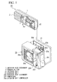
- FIG. 1 is a perspective view showing the interior unit and the air conditioner using the same in the present embodiment.
- the air conditioner shown in Fig. 1 consists of an interior unit 10 and an exterior unit 20, which are connected to each other via two refrigerant passages 21 through which refrigerant flows, electrical wiring (not shown), and the like.
- the refrigerant flows from the interior unit 10 to the exterior unit 20 through one of the refrigerant passages 21, and conversely, the refrigerant flows from the exterior unit 20 to the interior unit 10 through the other of the refrigerant passages 21.
- the basic structure of the interior unit 10 is the same as that of the above-explained conventional interior unit (see Fig. 5).
- the distinctive features of the interior unit 10 will be explained below, but other structural elements of the interior unit 10 are the same as those of the conventional interior unit and explanations thereof are omitted here.
- an exterior heat exchanger 20b In a body 20a of the exterior unit 20, an exterior heat exchanger 20b, a propeller fan 20c, a compressor 20f, an exterior unit controller 20g, and the like are provided.
- the exterior heat exchanger 20b includes refrigerant passages around which a plurality of plate fins are arranged. This exterior heat exchanger 20b is provided for performing the heat exchange between the refrigerant and the outside air. An air flow passing from the back face to the front face in the body 20a is generated using the propeller fan 20c, so that fresh air can be continuously drawn into the body 20a and the efficiency of the heat exchange in the exterior heat exchanger 20b can be improved.
- the compressor 20f converts gaseous refrigerant having a low temperature and a low pressure into gaseous refrigerant having a high temperature and a high pressure and discharges the high-temperature and high-pressure gaseous refrigerant. Therefore, the compressor 20f is one of the most important constituents of the refrigerant circuit which is provided for circulating the refrigerant between the interior unit 10 and the exterior unit 20.
- the refrigerant circuit includes the interior heat exchanger 7, the exterior heat exchanger 20b, the refrigerant passages 21, an expansion valve (not shown), a four-way valve (not shown) for directing the flow of the refrigerant, and the like.
- the exterior unit controller 20g includes various electrical circuit elements and controls the operations of the propeller fan 20c, the compressor 20f, and other devices provided in the exterior unit 20.
- high-temperature and high-pressure refrigerant output from the compressor 20f is transferred through the refrigerant passage 21 to the interior heat exchanger 7 of the interior unit 10.
- the air drawn through the front panel 2 by using the tangential fan 8 receives heat from the high-temperature and high-pressure refrigerant which passes through the interior heat exchanger 7. Accordingly, warm air is blown out from the air outlet 2a.
- the high-temperature and high-pressure refrigerant is condensed in the interior heat exchanger 7 so that high-temperature and high-pressure liquid refrigerant is produced.
- This high-temperature and high-pressure liquid refrigerant is again transferred through the refrigerant passage 21 to the exterior heat exchanger 20b of the exterior unit 20.
- the high-temperature and high-pressure liquid refrigerant passes through the expansion valve (not shown) so that the pressure of the refrigerant is reduced and low-temperature and low-pressure liquid refrigerant is produced.
- the low-temperature and low-pressure liquid refrigerant which passes through the exterior heat exchanger 20b receives heat from fresh outside air drawn into the body 20a by the propeller fan 20c, and the low-temperature and low-pressure liquid refrigerant is thus vaporized and converted into low-temperature and low-pressure gaseous refrigerant.
- This low-temperature and low-pressure gaseous refrigerant is transferred to the compressor 20f again, and the above-explained operation is repeated.
- the refrigerant also flows in the refrigerant circuit but in the reverse direction. That is, high-temperature and high-pressure gaseous refrigerant produced by the compressor 20f is transferred through the refrigerant passage 21 to the exterior heat exchanger 20b.
- the outside air receives heat from this high-temperature and high-pressure gaseous refrigerant, and this refrigerant is condensed and converted into high-temperature and high-pressure liquid refrigerant.
- This high-temperature and high-pressure liquid refrigerant passes through the expansion valve (not shown) and thus is converted into low-temperature and low-pressure refrigerant.
- This low-temperature and low-pressure refrigerant is again transferred through the refrigerant passage 21 to the interior heat exchanger 7.
- the transferred low-temperature and low-pressure liquid refrigerant receives heat from the inside air (i.e., room air) so that the inside air is cooled. Accordingly, the refrigerant itself is vaporized and converted into low-temperature and low-pressure gaseous refrigerant. This gaseous refrigerant is transferred to the compressor 20f again, and the above-explained operation is repeated.
- reference numeral 30 indicates the stabilizer 30 of the present embodiment, which is distinctively different from the above-explained conventional stabilizer 1b.
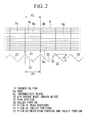
- Fig. 2 shows the relative positional relationship between the tangential fan 8 and the stabilizer 30 in the interior unit 10 of the present embodiment, viewed with a visual line (or sight) which is perpendicular to the axis of the tangential fan 8.
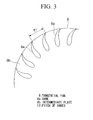
- Fig. 3 is a cross-sectional view in a section perpendicular to the axis of the tangential fan 8, which shows the general structure of a distinctive portion of the tangential fan 8.
- the tangential fan 8 (corresponding to the fan of the present invention) has a cylindrical form in which a plurality of vanes (or blades) 8a are circularly arranged. A plurality of intermediate plates 8b are inserted into this "cylinder" at a plurality of sections perpendicular to the axis of the cylinder, where these intermediate plates are provided for reinforcing the cylinder which consists of the vanes 8a.
- the tangential fan 8 can rotate around its axis by a drive motor (not shown).
- the interior heat exchanger 7 is positioned around the tangential fan 8 except for an area through which the air is drawn out from the tangential fan 8
- the stabilizer 30 is placed between the first portion 7a of the interior heat exchanger 7 and the tangential fan 8 so that the stabilizer 30 receives the draining liquid generated by the first portion 7a.
- the stabilizer 30 protrudes towards the opposite direction to the flow direction of the cold or warm air which is drawn into the tangential fan 8 (similar to the stabilizer 1b shown in Fig. 5).
- the head of the stabilizer 30 has a phase difference generating portion having a peak-valley form (which has a height t2 as shown in Fig. 2) for generating phase difference in the air drawn into the tangential fan 8.
- the pitch of the peak portions of the peak-valley form is equal to the pitch P2 of the intermediate plates 8b of the tangential fan 8.
- the phase difference generating portion has a peak-valley form which consists of peak portions 31 and valley portions 32 which are alternatingly arranged (that is, a saw-tooth form having sloped portions).
- the pitch t2 between each peak portion 31 and each valley portion 32 is substantially equal to the pitch t1 of the vanes 8a of the tangential fan 8 (see Fig. 3).
- the pitches t1 and t2 satisfy the condition "0.9 ⁇ t2/t1 ⁇ 1.1".
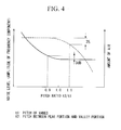
- Fig. 4 is a graph showing the changes in the noise level and the ventilation performance with respect to the relationships between the peak-valley shape of the tangential fan 8 and the pitch of the vanes of the tangential fan 8, where the horizontal axis indicates the pitch ratio t2/t1, and the vertical axis at the right side of the graph indicates the noise level while the vertical axis at the left side indicates the amount of (blown) air.
- the noise level gradually decreases as the pitch ratio t2/t1 graduall increases to 1.0.
- the pitch ratio t2/t1 exceeds 1.0, the noise level does not substantially change (i.e., the noise level is lowest).
- the pitch ratio t2/t1 is preferably equal to or more than approximately 0.9 (i.e., 0.9 ⁇ t2/t1).
- the amount of (blown) air which relates to the characteristics of the fan, as shown in Fig. 4, the amount of air is almost constant until the increasing pitch ratio t2/t1 is close to 1.0. After the pitch ratio t2/t1 exceeds approximately 1.0, the amount of air generally decreases.
- the pitch ratio t2/t1 is preferably equal to or less than approximately 1.1 (i.e., t2/t1 ⁇ 1.1).
- the pitch ratio t2/t1 preferably satisfies the condition "0.9 ⁇ t2/t1 ⁇ 1.1".
- the interior unit 10 of the present embodiment has the stabilizer 30 whose end has a peak-valley shape in which peak portions 31 and valley portions 32 are alternatingly formed.
- the pitch P1 of the peak portions 31 is substantially equal to the pitch P2 of the intermediate plates 8b
- the pitch t1 of the vanes 8a of the tangential fan 8 is substantially equal to the pitch t2 between each peak portion 31 and each valley portion 32.
- the peak-valley form (having a height t2) of the stabilizer 30 can generate phase differences (0 to 360 degrees corresponding to height 0 to t2) in air flow passing along each sloped portion to the tangential fan 8. Therefore, the strength of pressure waves generated by collision between the air flow and the vanes 8a of the tangential fan 8 can be suppressed, thereby reducing noise.
- the pitch of the peak portions 31 is smaller than that of the intermediate plates 8b
- the number of the peak portions 31 which interrupt the air flow directed to the tangential fan 8 can be reduced to an optimum number. Therefore, the resistance imposed on the air flow to the tangential fan 8 can be low, thereby preventing the ventilation performance from being degraded.
- the pitch t1 of the vanes 8a is substantially equal to the pitch t2 between each peak portion 31 and each valley portion 32. Therefore, the stabilizer 30 can have a peak-valley shape most suitable to the employed tangential fan 8. Accordingly, it is possible to simultaneously realize the sufficient amount of blown air and the reduction of noise.
- the interior unit 10 of the present embodiment it is possible to prevent the ventilation performance from being degraded and to reduce noise caused by the interference between the air flow and the tangential fan 8.
- each valley portion 32 faces the area between the alternative intermediate plates.
- the condition "0.9 ⁇ t2/t1 ⁇ 1.1" is satisfied.
- each peak portion 31 faces each intermediate plate 8b; thus, each area between the intermediate plates, which has higher ventilation efficiency and performance, faces each valley portion 32, thereby increasing the amount of passing air. That is, in comparison with another form in which each peak portion 31 faces the area between the adjacent intermediate plates, the ventilation performance can be improved.
Abstract
Description
Claims (4)
- An interior unit for an air conditioner, comprising:a fan (8) having a plurality of vanes (8a) which are circularly arranged to have a cylinder shape, wherein intermediate plates (8b) for reinforcing the cylinder are inserted at cross sections along the axis of the cylinder;an interior heat exchanger (7) which surrounds the fan except for an outlet area through which the air is drawn out from the fan; anda stabilizer (30), placed between the interior heat exchanger and the fan, for receiving draining liquid produced by the interior heat exchanger, wherein:the air which passes through the interior heat exchanger is then drawn into the fan according to the rotation of the fan, and the drawn air is discharged through the outlet area outside the interior unit, andthe interior unit is characterized in that:the end of the stabilizer, which is closest to the fan, has a peak-valley form consisting of peak portions and valley portions which are alternatingly arranged;the pitch of the peak portions is substantially equal to the pitch of the intermediate plates; andthe pitch of the vanes is substantially equal to the pitch between each peak portion and each valley portion.
- An interior unit as claimed in claim 1, characterized in that the peak portions respectively face the intermediate plates in a manner such that along the axial direction of the cylinder, the peak position of each peak portion substantially agrees with the position where the corresponding intermediate plate is inserted, and each valley portion faces an area between two adjacent intermediate plates.
- An interior unit as claimed in claim 1 or 2, characterized in that given pitch t1 of the vanes and pitch t2 between each peak portion and each valley portion, these pitches satisfy the condition "0.9 ≤ t2/t1 ≤ 1.1".
- An air conditioner characterized by comprising an interior unit as claimed in any one of claims 1 to 3, wherein the air conditioner also comprises an exterior unit which includes an exterior heat exchanger, a compressor for transferring high-temperature and high-pressure gaseous refrigerant to the interior heat exchanger of the interior unit, and various electrical circuit elements.
Applications Claiming Priority (4)
| Application Number | Priority Date | Filing Date | Title |
|---|---|---|---|
| JP2001088366 | 2001-03-26 | ||
| JP2001088366 | 2001-03-26 | ||
| JP2002023894A JP3593106B2 (en) | 2001-03-26 | 2002-01-31 | Indoor units and air conditioners |
| JP2002023894 | 2002-01-31 |
Publications (3)
| Publication Number | Publication Date |
|---|---|
| EP1245907A2 true EP1245907A2 (en) | 2002-10-02 |
| EP1245907A3 EP1245907A3 (en) | 2004-04-07 |
| EP1245907B1 EP1245907B1 (en) | 2006-06-14 |
Family
ID=26612090
Family Applications (1)
| Application Number | Title | Priority Date | Filing Date |
|---|---|---|---|
| EP02004111A Expired - Lifetime EP1245907B1 (en) | 2001-03-26 | 2002-02-25 | Interior unit for air conditioner, and air conditioner comprising the same |
Country Status (6)
| Country | Link |
|---|---|
| EP (1) | EP1245907B1 (en) |
| JP (1) | JP3593106B2 (en) |
| CN (1) | CN1178029C (en) |
| AT (1) | ATE330185T1 (en) |
| DE (1) | DE60212234D1 (en) |
| ES (1) | ES2265459T3 (en) |
Cited By (3)
| Publication number | Priority date | Publication date | Assignee | Title |
|---|---|---|---|---|
| US20180112888A1 (en) * | 2016-10-21 | 2018-04-26 | Samsung Electronics Co., Ltd | Air conditioner |
| US10895388B2 (en) * | 2016-02-03 | 2021-01-19 | Mitsubishi Electric Corporation | Indoor unit air-conditioning apparatus |
| EP3985323A4 (en) * | 2019-06-17 | 2022-08-03 | Panasonic Intellectual Property Management Co., Ltd. | Air conditioner |
Families Citing this family (6)
| Publication number | Priority date | Publication date | Assignee | Title |
|---|---|---|---|---|
| KR101392092B1 (en) | 2007-10-22 | 2014-05-12 | 엘지전자 주식회사 | A ceiling-mounted type air conditioner |
| KR101392088B1 (en) | 2007-10-22 | 2014-05-12 | 엘지전자 주식회사 | A ceiling-mounted type air conditioner |
| JP5950810B2 (en) * | 2012-12-13 | 2016-07-13 | 三菱電機株式会社 | Air conditioner indoor unit |
| JP6554665B2 (en) * | 2015-12-09 | 2019-08-07 | パナソニックIpマネジメント株式会社 | Air conditioner |
| CN106556129A (en) * | 2016-12-02 | 2017-04-05 | 珠海格力电器股份有限公司 | Air-conditioning dispensing device for water and air-conditioning equipment |
| CN110671747A (en) * | 2019-11-04 | 2020-01-10 | 珠海格力电器股份有限公司 | Indoor unit and air conditioner with same |
Citations (6)
| Publication number | Priority date | Publication date | Assignee | Title |
|---|---|---|---|---|
| US3034702A (en) * | 1957-11-21 | 1962-05-15 | Westerasmaskiner Ab | Fan having a great axial length and comprising an air inlet at both ends |
| GB1066053A (en) * | 1963-04-22 | 1967-04-19 | Hoover Ltd | Improvements relating to cross-flow machines for inducing flow of fluids |
| SU1657754A1 (en) * | 1989-06-05 | 1991-06-23 | Университет дружбы народов им.Патриса Лумумбы | Fan |
| US5094586A (en) * | 1989-06-23 | 1992-03-10 | Hitachi, Ltd. | Air conditioner employing cross-flow fan |
| US5868551A (en) * | 1997-05-02 | 1999-02-09 | American Standard Inc. | Tangential fan cutoff |
| JPH11304178A (en) * | 1998-04-24 | 1999-11-05 | Samsung Electronics Co Ltd | Transverse fan air blower for air conditioner |
-
2002
- 2002-01-31 JP JP2002023894A patent/JP3593106B2/en not_active Expired - Fee Related
- 2002-02-25 DE DE60212234T patent/DE60212234D1/en not_active Expired - Lifetime
- 2002-02-25 ES ES02004111T patent/ES2265459T3/en not_active Expired - Lifetime
- 2002-02-25 EP EP02004111A patent/EP1245907B1/en not_active Expired - Lifetime
- 2002-02-25 AT AT02004111T patent/ATE330185T1/en not_active IP Right Cessation
- 2002-03-21 CN CNB021077606A patent/CN1178029C/en not_active Expired - Fee Related
Patent Citations (6)
| Publication number | Priority date | Publication date | Assignee | Title |
|---|---|---|---|---|
| US3034702A (en) * | 1957-11-21 | 1962-05-15 | Westerasmaskiner Ab | Fan having a great axial length and comprising an air inlet at both ends |
| GB1066053A (en) * | 1963-04-22 | 1967-04-19 | Hoover Ltd | Improvements relating to cross-flow machines for inducing flow of fluids |
| SU1657754A1 (en) * | 1989-06-05 | 1991-06-23 | Университет дружбы народов им.Патриса Лумумбы | Fan |
| US5094586A (en) * | 1989-06-23 | 1992-03-10 | Hitachi, Ltd. | Air conditioner employing cross-flow fan |
| US5868551A (en) * | 1997-05-02 | 1999-02-09 | American Standard Inc. | Tangential fan cutoff |
| JPH11304178A (en) * | 1998-04-24 | 1999-11-05 | Samsung Electronics Co Ltd | Transverse fan air blower for air conditioner |
Non-Patent Citations (1)
| Title |
|---|
| PATENT ABSTRACTS OF JAPAN vol. 2000, no. 02, 29 February 2000 (2000-02-29) & JP 11 304178 A (SAMSUNG ELECTRONICS CO LTD), 5 November 1999 (1999-11-05) * |
Cited By (3)
| Publication number | Priority date | Publication date | Assignee | Title |
|---|---|---|---|---|
| US10895388B2 (en) * | 2016-02-03 | 2021-01-19 | Mitsubishi Electric Corporation | Indoor unit air-conditioning apparatus |
| US20180112888A1 (en) * | 2016-10-21 | 2018-04-26 | Samsung Electronics Co., Ltd | Air conditioner |
| EP3985323A4 (en) * | 2019-06-17 | 2022-08-03 | Panasonic Intellectual Property Management Co., Ltd. | Air conditioner |
Also Published As
| Publication number | Publication date |
|---|---|
| CN1178029C (en) | 2004-12-01 |
| JP3593106B2 (en) | 2004-11-24 |
| ATE330185T1 (en) | 2006-07-15 |
| JP2002357331A (en) | 2002-12-13 |
| EP1245907B1 (en) | 2006-06-14 |
| EP1245907A3 (en) | 2004-04-07 |
| DE60212234D1 (en) | 2006-07-27 |
| CN1376879A (en) | 2002-10-30 |
| ES2265459T3 (en) | 2007-02-16 |
Similar Documents
| Publication | Publication Date | Title |
|---|---|---|
| EP1361398B1 (en) | Indoor unit for air conditioner | |
| KR20090088440A (en) | Sirocco fan and air conditioner | |
| KR20030035328A (en) | Outdoor unit of air conditioner | |
| EP1243864B1 (en) | Indoor unit and air-conditioner | |
| EP1245907B1 (en) | Interior unit for air conditioner, and air conditioner comprising the same | |
| EP1632725B1 (en) | Air conditioner | |
| JP7204872B2 (en) | Heat source equipment and refrigeration cycle equipment | |
| EP1245908B1 (en) | Air conditioner and indoor unit therefor | |
| CN101070980A (en) | Pipeline-type air conditioner | |
| JP2007285628A (en) | Air conditioning system | |
| CN215062438U (en) | Indoor machine of air conditioner | |
| CN215001915U (en) | Indoor machine of air conditioner | |
| EP2096365B1 (en) | Heat source unit installed inside building | |
| JP3564414B2 (en) | Indoor unit and air conditioner | |
| JP3621892B2 (en) | Indoor unit and air conditioner | |
| CN109891101B (en) | Propeller fan, outdoor unit, and refrigeration cycle device | |
| WO2024042987A1 (en) | Air conditioning device | |
| KR100402885B1 (en) | Axial fan for Indoor unit of airconditioner | |
| WO2021039597A1 (en) | Blowing device and heat pump unit | |
| JP7229392B2 (en) | indoor unit of air conditioner | |
| JP5818984B2 (en) | Outdoor unit of air conditioner and air conditioner provided with the same | |
| CN213542650U (en) | Indoor air conditioner | |
| JP2001108261A (en) | Outdoor machine of air-conditioner | |
| JPH07260178A (en) | Air conditioner | |
| KR100261478B1 (en) | Indoor unit of separable type airconditioner |
Legal Events
| Date | Code | Title | Description |
|---|---|---|---|
| PUAI | Public reference made under article 153(3) epc to a published international application that has entered the european phase |
Free format text: ORIGINAL CODE: 0009012 |
|
| 17P | Request for examination filed |
Effective date: 20020225 |
|
| AK | Designated contracting states |
Kind code of ref document: A2 Designated state(s): AT BE CH CY DE DK ES FI FR GB GR IE IT LI LU MC NL PT SE TR |
|
| AX | Request for extension of the european patent |
Free format text: AL;LT;LV;MK;RO;SI |
|
| PUAL | Search report despatched |
Free format text: ORIGINAL CODE: 0009013 |
|
| AK | Designated contracting states |
Kind code of ref document: A3 Designated state(s): AT BE CH CY DE DK ES FI FR GB GR IE IT LI LU MC NL PT SE TR |
|
| AX | Request for extension of the european patent |
Extension state: AL LT LV MK RO SI |
|
| RIC1 | Information provided on ipc code assigned before grant |
Ipc: 7F 04D 29/66 B Ipc: 7F 24F 13/24 B Ipc: 7F 24F 1/00 A |
|
| AKX | Designation fees paid |
Designated state(s): AT BE CH CY DE DK ES FI FR GB GR IE IT LI LU MC NL PT SE TR |
|
| GRAP | Despatch of communication of intention to grant a patent |
Free format text: ORIGINAL CODE: EPIDOSNIGR1 |
|
| RIN1 | Information on inventor provided before grant (corrected) |
Inventor name: IZUMI, HAZIME,C/O MITSUBISHI HEAVY IND.,LTD Inventor name: SUZUKI, KAZUHIRO,C/O MITSUBISHI HEAVY IND.,LTD Inventor name: KONDOU, FUMIO,C/O MITSUBISHI HEAVY IND., LTD Inventor name: SUENAGA, KIYOSHI,C/O MITSUBISHI HEAVY IND., LTD Inventor name: OKADA, YUUJI,C/O MITSUBISHI HEAVY IND., LTD Inventor name: TOMINAGA, TETSUO,C/O MITSUBISHI HEAVY IND., LTD |
|
| GRAS | Grant fee paid |
Free format text: ORIGINAL CODE: EPIDOSNIGR3 |
|
| GRAA | (expected) grant |
Free format text: ORIGINAL CODE: 0009210 |
|
| AK | Designated contracting states |
Kind code of ref document: B1 Designated state(s): AT BE CH CY DE DK ES FI FR GB GR IE IT LI LU MC NL PT SE TR |
|
| PG25 | Lapsed in a contracting state [announced via postgrant information from national office to epo] |
Ref country code: IT Free format text: LAPSE BECAUSE OF FAILURE TO SUBMIT A TRANSLATION OF THE DESCRIPTION OR TO PAY THE FEE WITHIN THE PRESCRIBED TIME-LIMIT;WARNING: LAPSES OF ITALIAN PATENTS WITH EFFECTIVE DATE BEFORE 2007 MAY HAVE OCCURRED AT ANY TIME BEFORE 2007. THE CORRECT EFFECTIVE DATE MAY BE DIFFERENT FROM THE ONE RECORDED. Effective date: 20060614 Ref country code: CH Free format text: LAPSE BECAUSE OF FAILURE TO SUBMIT A TRANSLATION OF THE DESCRIPTION OR TO PAY THE FEE WITHIN THE PRESCRIBED TIME-LIMIT Effective date: 20060614 Ref country code: FI Free format text: LAPSE BECAUSE OF FAILURE TO SUBMIT A TRANSLATION OF THE DESCRIPTION OR TO PAY THE FEE WITHIN THE PRESCRIBED TIME-LIMIT Effective date: 20060614 Ref country code: AT Free format text: LAPSE BECAUSE OF FAILURE TO SUBMIT A TRANSLATION OF THE DESCRIPTION OR TO PAY THE FEE WITHIN THE PRESCRIBED TIME-LIMIT Effective date: 20060614 Ref country code: LI Free format text: LAPSE BECAUSE OF FAILURE TO SUBMIT A TRANSLATION OF THE DESCRIPTION OR TO PAY THE FEE WITHIN THE PRESCRIBED TIME-LIMIT Effective date: 20060614 Ref country code: NL Free format text: LAPSE BECAUSE OF FAILURE TO SUBMIT A TRANSLATION OF THE DESCRIPTION OR TO PAY THE FEE WITHIN THE PRESCRIBED TIME-LIMIT Effective date: 20060614 Ref country code: BE Free format text: LAPSE BECAUSE OF FAILURE TO SUBMIT A TRANSLATION OF THE DESCRIPTION OR TO PAY THE FEE WITHIN THE PRESCRIBED TIME-LIMIT Effective date: 20060614 |
|
| REG | Reference to a national code |
Ref country code: GB Ref legal event code: FG4D |
|
| REG | Reference to a national code |
Ref country code: CH Ref legal event code: EP |
|
| REG | Reference to a national code |
Ref country code: IE Ref legal event code: FG4D |
|
| REF | Corresponds to: |
Ref document number: 60212234 Country of ref document: DE Date of ref document: 20060727 Kind code of ref document: P |
|
| PG25 | Lapsed in a contracting state [announced via postgrant information from national office to epo] |
Ref country code: SE Free format text: LAPSE BECAUSE OF FAILURE TO SUBMIT A TRANSLATION OF THE DESCRIPTION OR TO PAY THE FEE WITHIN THE PRESCRIBED TIME-LIMIT Effective date: 20060914 Ref country code: DK Free format text: LAPSE BECAUSE OF FAILURE TO SUBMIT A TRANSLATION OF THE DESCRIPTION OR TO PAY THE FEE WITHIN THE PRESCRIBED TIME-LIMIT Effective date: 20060914 |
|
| PG25 | Lapsed in a contracting state [announced via postgrant information from national office to epo] |
Ref country code: DE Free format text: LAPSE BECAUSE OF FAILURE TO SUBMIT A TRANSLATION OF THE DESCRIPTION OR TO PAY THE FEE WITHIN THE PRESCRIBED TIME-LIMIT Effective date: 20060915 |
|
| PG25 | Lapsed in a contracting state [announced via postgrant information from national office to epo] |
Ref country code: PT Free format text: LAPSE BECAUSE OF FAILURE TO SUBMIT A TRANSLATION OF THE DESCRIPTION OR TO PAY THE FEE WITHIN THE PRESCRIBED TIME-LIMIT Effective date: 20061114 |
|
| NLV1 | Nl: lapsed or annulled due to failure to fulfill the requirements of art. 29p and 29m of the patents act | ||
| REG | Reference to a national code |
Ref country code: CH Ref legal event code: PL |
|
| REG | Reference to a national code |
Ref country code: ES Ref legal event code: FG2A Ref document number: 2265459 Country of ref document: ES Kind code of ref document: T3 |
|
| PG25 | Lapsed in a contracting state [announced via postgrant information from national office to epo] |
Ref country code: MC Free format text: LAPSE BECAUSE OF NON-PAYMENT OF DUE FEES Effective date: 20070228 |
|
| PLBE | No opposition filed within time limit |
Free format text: ORIGINAL CODE: 0009261 |
|
| STAA | Information on the status of an ep patent application or granted ep patent |
Free format text: STATUS: NO OPPOSITION FILED WITHIN TIME LIMIT |
|
| EN | Fr: translation not filed | ||
| 26N | No opposition filed |
Effective date: 20070315 |
|
| PG25 | Lapsed in a contracting state [announced via postgrant information from national office to epo] |
Ref country code: IE Free format text: LAPSE BECAUSE OF NON-PAYMENT OF DUE FEES Effective date: 20070226 |
|
| PG25 | Lapsed in a contracting state [announced via postgrant information from national office to epo] |
Ref country code: FR Free format text: LAPSE BECAUSE OF FAILURE TO SUBMIT A TRANSLATION OF THE DESCRIPTION OR TO PAY THE FEE WITHIN THE PRESCRIBED TIME-LIMIT Effective date: 20070309 Ref country code: GR Free format text: LAPSE BECAUSE OF FAILURE TO SUBMIT A TRANSLATION OF THE DESCRIPTION OR TO PAY THE FEE WITHIN THE PRESCRIBED TIME-LIMIT Effective date: 20060915 |
|
| PG25 | Lapsed in a contracting state [announced via postgrant information from national office to epo] |
Ref country code: FR Free format text: LAPSE BECAUSE OF FAILURE TO SUBMIT A TRANSLATION OF THE DESCRIPTION OR TO PAY THE FEE WITHIN THE PRESCRIBED TIME-LIMIT Effective date: 20060614 |
|
| PG25 | Lapsed in a contracting state [announced via postgrant information from national office to epo] |
Ref country code: LU Free format text: LAPSE BECAUSE OF NON-PAYMENT OF DUE FEES Effective date: 20070225 Ref country code: CY Free format text: LAPSE BECAUSE OF FAILURE TO SUBMIT A TRANSLATION OF THE DESCRIPTION OR TO PAY THE FEE WITHIN THE PRESCRIBED TIME-LIMIT Effective date: 20060614 |
|
| PG25 | Lapsed in a contracting state [announced via postgrant information from national office to epo] |
Ref country code: TR Free format text: LAPSE BECAUSE OF FAILURE TO SUBMIT A TRANSLATION OF THE DESCRIPTION OR TO PAY THE FEE WITHIN THE PRESCRIBED TIME-LIMIT Effective date: 20060614 |
|
| REG | Reference to a national code |
Ref country code: GB Ref legal event code: 732E Free format text: REGISTERED BETWEEN 20171130 AND 20171206 |
|
| PGFP | Annual fee paid to national office [announced via postgrant information from national office to epo] |
Ref country code: GB Payment date: 20190220 Year of fee payment: 18 Ref country code: ES Payment date: 20190304 Year of fee payment: 18 Ref country code: IT Payment date: 20190221 Year of fee payment: 18 |
|
| GBPC | Gb: european patent ceased through non-payment of renewal fee |
Effective date: 20200225 |
|
| PG25 | Lapsed in a contracting state [announced via postgrant information from national office to epo] |
Ref country code: GB Free format text: LAPSE BECAUSE OF NON-PAYMENT OF DUE FEES Effective date: 20200225 |
|
| REG | Reference to a national code |
Ref country code: ES Ref legal event code: FD2A Effective date: 20210707 |
|
| PG25 | Lapsed in a contracting state [announced via postgrant information from national office to epo] |
Ref country code: IT Free format text: LAPSE BECAUSE OF NON-PAYMENT OF DUE FEES Effective date: 20200225 |
|
| PG25 | Lapsed in a contracting state [announced via postgrant information from national office to epo] |
Ref country code: ES Free format text: LAPSE BECAUSE OF NON-PAYMENT OF DUE FEES Effective date: 20200226 |