EP3929463A1 - Multi-speed planetary transmission - Google Patents
Multi-speed planetary transmission Download PDFInfo
- Publication number
- EP3929463A1 EP3929463A1 EP21191020.3A EP21191020A EP3929463A1 EP 3929463 A1 EP3929463 A1 EP 3929463A1 EP 21191020 A EP21191020 A EP 21191020A EP 3929463 A1 EP3929463 A1 EP 3929463A1
- Authority
- EP
- European Patent Office
- Prior art keywords
- selective coupler
- gearset
- planetary gearset
- planetary
- component
- Prior art date
- Legal status (The legal status is an assumption and is not a legal conclusion. Google has not performed a legal analysis and makes no representation as to the accuracy of the status listed.)
- Granted
Links
Images






Classifications
-
- F—MECHANICAL ENGINEERING; LIGHTING; HEATING; WEAPONS; BLASTING
- F16—ENGINEERING ELEMENTS AND UNITS; GENERAL MEASURES FOR PRODUCING AND MAINTAINING EFFECTIVE FUNCTIONING OF MACHINES OR INSTALLATIONS; THERMAL INSULATION IN GENERAL
- F16H—GEARING
- F16H3/00—Toothed gearings for conveying rotary motion with variable gear ratio or for reversing rotary motion
- F16H3/44—Toothed gearings for conveying rotary motion with variable gear ratio or for reversing rotary motion using gears having orbital motion
- F16H3/62—Gearings having three or more central gears
- F16H3/66—Gearings having three or more central gears composed of a number of gear trains without drive passing from one train to another
-
- F—MECHANICAL ENGINEERING; LIGHTING; HEATING; WEAPONS; BLASTING
- F16—ENGINEERING ELEMENTS AND UNITS; GENERAL MEASURES FOR PRODUCING AND MAINTAINING EFFECTIVE FUNCTIONING OF MACHINES OR INSTALLATIONS; THERMAL INSULATION IN GENERAL
- F16H—GEARING
- F16H2200/00—Transmissions for multiple ratios
- F16H2200/003—Transmissions for multiple ratios characterised by the number of forward speeds
- F16H2200/0065—Transmissions for multiple ratios characterised by the number of forward speeds the gear ratios comprising nine forward speeds
-
- F—MECHANICAL ENGINEERING; LIGHTING; HEATING; WEAPONS; BLASTING
- F16—ENGINEERING ELEMENTS AND UNITS; GENERAL MEASURES FOR PRODUCING AND MAINTAINING EFFECTIVE FUNCTIONING OF MACHINES OR INSTALLATIONS; THERMAL INSULATION IN GENERAL
- F16H—GEARING
- F16H2200/00—Transmissions for multiple ratios
- F16H2200/003—Transmissions for multiple ratios characterised by the number of forward speeds
- F16H2200/0069—Transmissions for multiple ratios characterised by the number of forward speeds the gear ratios comprising ten forward speeds
-
- F—MECHANICAL ENGINEERING; LIGHTING; HEATING; WEAPONS; BLASTING
- F16—ENGINEERING ELEMENTS AND UNITS; GENERAL MEASURES FOR PRODUCING AND MAINTAINING EFFECTIVE FUNCTIONING OF MACHINES OR INSTALLATIONS; THERMAL INSULATION IN GENERAL
- F16H—GEARING
- F16H2200/00—Transmissions for multiple ratios
- F16H2200/20—Transmissions using gears with orbital motion
- F16H2200/2002—Transmissions using gears with orbital motion characterised by the number of sets of orbital gears
- F16H2200/2012—Transmissions using gears with orbital motion characterised by the number of sets of orbital gears with four sets of orbital gears
-
- F—MECHANICAL ENGINEERING; LIGHTING; HEATING; WEAPONS; BLASTING
- F16—ENGINEERING ELEMENTS AND UNITS; GENERAL MEASURES FOR PRODUCING AND MAINTAINING EFFECTIVE FUNCTIONING OF MACHINES OR INSTALLATIONS; THERMAL INSULATION IN GENERAL
- F16H—GEARING
- F16H2200/00—Transmissions for multiple ratios
- F16H2200/20—Transmissions using gears with orbital motion
- F16H2200/203—Transmissions using gears with orbital motion characterised by the engaging friction means not of the freewheel type, e.g. friction clutches or brakes
- F16H2200/2046—Transmissions using gears with orbital motion characterised by the engaging friction means not of the freewheel type, e.g. friction clutches or brakes with six engaging means
Definitions
- the present disclosure relates to a multi-speed transmission and in particular to a multi-speed transmission including a plurality of planetary gearsets and a plurality of selective couplers to achieve at least nine forward speed ratios and at least one reverse speed ratio.
- Multi-speed transmissions use a plurality of planetary gearsets, selective couplers, interconnectors, and additional elements to achieve a plurality of forward and reverse speed ratios.
- Exemplary multi-speed transmissions are disclosed in US Published Patent Application No. 2016/0047440, serial no. 14/457,592, titled MULTI-SPEED TRANSMISSION, filed August 12, 2014 , the entire disclosure of which is expressly incorporated by reference herein.
- a transmission as defined in claim 1 is provided.
- the dependent claims define preferred and/or advantageous embodiments of the invention.
- the present disclosure in particular provides a multi-speed transmission including a plurality of planetary gearsets and a plurality of selective couplers to achieve at least nine forward speed ratios.
- the plurality of planetary gearsets may include a first planetary gearset, a second planetary gearset, a third planetary gearset, and a fourth planetary gearset.
- the plurality of selective couplers may include a number of clutches and a number of brakes.
- the present disclosure provides a multi-speed transmission having four planetary gearsets and six selective couplers.
- the six selective couplers may include four clutches and two brakes.
- the six selective couplers may include three clutches and three brakes.
- first, second, third, and fourth is used in reference to various gearsets, gears, gearset components, interconnectors, selective couplers, and other components. Such use is not intended to denote an ordering of the components. Rather, numeric terminology is used to assist the reader in identifying the component being referenced and should not be narrowly interpreted as providing a specific order of components.
- a first planetary gearset identified in the drawings may support any one of the plurality of planetary gearsets recited in the claims, including the first planetary gearset, the second planetary gearset, the third planetary gearset, and the fourth planetary gearset, depending on the language of the claims.
- a transmission comprising an at least one stationary member; an input member rotatable relative to the at least one stationary member; a plurality of planetary gearsets operatively coupled to the input member; an output member operatively coupled to the input member through the plurality of planetary gearsets and rotatable relative to the at least one stationary member; a first interconnector fixedly couples the second gearset component of the first planetary gearset to one of the second planetary gearset and the third planetary gearset; a second interconnector fixedly couples the third gearset component of the first planetary gearset to at least one of the second planetary gearset, the third planetary gearset, and the fourth planetary gearset; and a plurality of selective couplers.
- the plurality of selective couplers includes a first number of clutches and a second number of brakes, wherein the first number is at least equal to the second number.
- Each of the plurality of planetary gearsets includes a first gearset component, a second gearset component, and a third gearset component.
- the plurality of planetary gearsets including a first planetary gearset, a second planetary gearset, a third planetary gearset, and a fourth planetary gearset.
- the input member is fixedly coupled to the first gearset component of the first planetary gearset.
- the output member is fixedly coupled to the fourth planetary gearset.
- the input member is further fixedly coupled to the second planetary gearset. In a variation thereof, the input member is fixedly coupled to the first gearset component of the second planetary gearset.
- the second gearset component of the first planetary gearset is fixedly coupled to the third gearset component of the third planetary gearset.
- the second gearset component of the first planetary gearset is fixedly coupled to the third gearset component of the second planetary gearset.
- the third gearset component of the first planetary gearset is fixedly coupled to at least two of the second planetary gearset, the third planetary gearset, and the fourth planetary gearset.
- the third gearset component of the first planetary gearset is fixedly coupled to the third gearset component of the second planetary gearset and the first gearset component of the fourth planetary gearset.
- the third gearset component of the first planetary gearset is fixedly coupled to the first gearset component of the second planetary gearset and the first gearset component of the fourth planetary gearset.
- the second gearset component of the second planetary gearset is fixedly coupled to the third gearset component of the third planetary gearset.
- the third gearset component of the first planetary gearset is fixedly coupled to the first gearset component of the third planetary gearset.
- the output member is fixedly coupled to the third gearset component of the fourth planetary gearset.
- the output member is fixedly coupled to the second gearset component of the fourth planetary gearset. In a variation thereof, the output member is further fixedly coupled to the third planetary gearset. In a further variation thereof, the output member is further fixedly coupled to the third gearset component of the third planetary gearset.
- the at least one stationary member includes a housing, the housing having a first end and a second end, wherein the input member is accessible proximate the first end of the housing; the output member is accessible proximate the second end of the housing; the first planetary gearset is positioned between the first end of the housing and the second planetary gearset; the second planetary gearset is positioned between the first planetary gearset and the third planetary gearset; the third planetary gearset is positioned between the second planetary gearset and the fourth planetary gearset; and the fourth planetary gearset is positioned between the third planetary gearset and the second end of the housing.
- each of the first planetary gearset, the second planetary gearset, the third planetary gearset, and the fourth planetary gearset is a simple planetary gearset.
- the first gearset component of the first planetary gearset is a first sun gear
- the first gearset component of the second planetary gearset is a second sun gear
- the first gearset component of the third planetary gearset is a third sun gear
- the first gearset component of the fourth planetary gearset is a fourth sun gear
- the second gearset component of the first planetary gearset is a first planet carrier
- the second gearset component of the second planetary gearset is a second planet carrier
- the second gearset component of the third planetary gearset is a third planet carrier
- the second gearset component of the fourth planetary gearset is a fourth planet carrier
- the third gearset component of the first planetary gearset is a first ring gear
- the third gearset component of the second planetary gearset is a second ring gear
- the plurality of selective couplers include: a first selective coupler which, when engaged, fixedly couples the second gearset component of the third planetary gearset to the at least one stationary member; a second selective coupler which, when engaged, fixedly couples the first gearset component of the third planetary gearset to the at least one stationary member; a third selective coupler which, when engaged, fixedly couples the first gearset component of the first planetary gearset and the first gearset component of the second planetary gearset to the second gearset component of the fourth planetary gearset; a fourth selective coupler which, when engaged, fixedly couples the second gearset component of the third planetary gearset to the third gearset component of the first planetary gearset, the third gearset component of the second planetary gearset, and the first gearset component of the fourth planetary gearset; a fifth selective coupler which, when engaged, fixedly couples the second gearset component of the second planetary gearset to the second gearset component of the fourth planetary gearset; and a sixth selective coupler which, when engaged, when engaged, fixed
- the plurality of selective couplers include: a first selective coupler which, when engaged, fixedly couples the second gearset component of the third planetary gearset to the at least one stationary member; a second selective coupler which, when engaged, fixedly couples the first gearset component of the third planetary gearset to the at least one stationary member; a third selective coupler which, when engaged, fixedly couples the first gearset component of the first planetary gearset and the first gearset component of the second planetary gearset to the second gearset component of the fourth planetary gearset; a fourth selective coupler which, when engaged, fixedly couples the second gearset component of the third planetary gearset to the third gearset component of the first planetary gearset, the third gearset component of the second planetary gearset, and the first gearset component of the fourth planetary gearset; a fifth selective coupler which, when engaged, fixedly couples the second gearset component of the second planetary gearset to the second gearset component of the fourth planetary gearset; and a sixth selective coupler which, when engaged, fixedly couples the
- the plurality of selective couplers include: a first selective coupler which, when engaged, fixedly couples the second gearset component of the third planetary gearset to the at least one stationary member; a second selective coupler which, when engaged, fixedly couples the first gearset component of the third planetary gearset to the at least one stationary member; a third selective coupler which, when engaged, fixedly couples the first gearset component of the first planetary gearset to the second gearset component of the fourth planetary gearset; a fourth selective coupler which, when engaged, fixedly couples the third gearset component of the first planetary gearset, the first gearset component of the second planetary gearset, and the first gearset component of the fourth planetary gearset to the second gearset component of the third planetary gearset; a fifth selective coupler which, when engaged, fixedly couples the second gearset component of the first planetary gearset and the third gearset component of the second planetary gearset to the second gearset component of the fourth planetary gearset; and a sixth selective coupler which, when engaged, fixedly couples the
- the plurality of selective couplers include: a first selective coupler which, when engaged, fixedly couples the second gearset component of the third planetary gearset to the at least one stationary member; a second selective coupler which, when engaged, fixedly couples the first gearset component of the third planetary gearset to the at least one stationary member; a third selective coupler which, when engaged, fixedly couples the first gearset component of the first planetary gearset to the second gearset component of the fourth planetary gearset; a fourth selective coupler which, when engaged, fixedly couples the third gearset component of the first planetary gearset, the first gearset component of the second planetary gearset, and the first gearset component of the fourth planetary gearset to the second gearset component of the third planetary gearset; a fifth selective coupler which, when engaged, fixedly couples the second gearset component of the first planetary gearset and the third gearset component of the second planetary gearset to the second gearset component of the fourth planetary gearset; and a sixth selective coupler which, when engaged, fixedly couples the
- the plurality of selective couplers include: a first selective coupler which, when engaged, fixedly couples the second gearset component of the second planetary gearset to the at least one stationary member; a second selective coupler which, when engaged, fixedly couples the first gearset component of the second planetary gearset to the at least one stationary member; a third selective coupler which, when engaged, fixedly couples the second gearset component of the third planetary gearset and the third gearset component of the fourth planetary gearset to the first gearset component of the first planetary gearset; a fourth selective coupler which, when engaged, fixedly couples the first gearset component of the first planetary gearset to the first gearset component of the fourth planetary gearset; a fifth selective coupler which, when engaged, fixedly couples the third gearset component of the first planetary gearset and the first gearset component of the third planetary gearset to the second gearset component of the second planetary gearset; and a sixth selective coupler which, when engaged, fixedly couples the second gearset component of the third planetary gearset to the second
- the plurality of selective couplers include: a first selective coupler which, when engaged, fixedly couples the second gearset component of the second planetary gearset to the at least one stationary member; a second selective coupler which, when engaged, fixedly couples the first gearset component of the second planetary gearset to the at least one stationary member; a third selective coupler which, when engaged, fixedly couples the second gearset component of the third planetary gearset and the third gearset component of the fourth planetary gearset to the first gearset component of the first planetary gearset; a fourth selective coupler which, when engaged, fixedly couples the first gearset component of the first planetary gearset to the first gearset component of the fourth planetary gearset; a fifth selective coupler which, when engaged, fixedly couples the third gearset component of the first planetary gearset and the first gearset component of the third planetary gearset to the second gearset component of the second planetary gearset; and a sixth selective coupler which, when engaged, fixedly couples the second gearset component of the third
- the present disclosure in particular comprises the following aspects:
- a selective coupler is a device which may be actuated to fixedly couple two or more components together.
- a selective coupler fixedly couples two or more components to rotate together as a unit when the selective coupler is in an engaged configuration. Further, the two or more components may be rotatable relative to each other when the selective coupler is in a disengaged configuration.
- the terms “couples”, “coupled”, “coupler” and variations thereof are used to include both arrangements wherein the two or more components are in direct physical contact and arrangements wherein the two or more components are not in direct contact with each other (e. g., the components are “coupled” via at least a third component), but yet still cooperate or interact with each other.
- a first exemplary selective coupler is a clutch.
- a clutch couples two or more rotating components to one another so that the two or more rotating components rotate together as a unit in an engaged configuration and permits relative rotation between the two or more rotating components in the disengaged position.
- Exemplary clutches may be shiftable friction-locked multi-disk clutches, shiftable form-locking claw or conical clutches, wet clutches, or any other known form of a clutch.
- a second exemplary selective coupler is a brake.
- a brake couples one or more rotatable components to a stationary component to hold the one or more rotatable components stationary relative to the stationary component in the engaged configuration and permits rotation of the one or more components relative to the stationary component in the disengaged configuration.
- Exemplary brakes may be configured as shiftable-friction-locked disk brakes, shiftable friction-locked band brakes, shiftable form-locking claw or conical brakes, or any other known form of a brake.
- Selective couplers may be actively controlled devices or passive devices.
- Exemplary actively controlled devices include hydraulically actuated clutch or brake elements and electrically actuated clutch or brake elements. Additional details regarding systems and methods for controlling selective couplers are disclosed in the above-incorporated US Published Patent Application No. 2016/0047440 .
- various components of the disclosed transmission embodiments may be fixedly coupled together continuously throughout the operation of the disclosed transmissions.
- Components may be fixedly coupled together either permanently or removably.
- Components may be fixedly coupled together through spline connections, press fitting, fasteners, welding, machined or formed functional portions of a unitary piece, or other suitable methods of connecting components.
- the disclosed transmission embodiments include a plurality of planetary gearsets.
- Each planetary gearset includes at least four components: a sun gear; a ring gear; a plurality of planet gears; and a carrier that is rotatably coupled to and carries the planet gears.
- the teeth of the sun gear are intermeshed with the teeth of the planet gears which are in turn engaged with the teeth of the ring gear.
- Each of these components may also be referred to as a gearset component.
- some planetary gearsets may include further components than those explicitly identified.
- one or more of the planetary gearsets may include two sets of planet gears. A first set of planet gears may intermesh with the sun gear while the second set of planet gears intermesh with the first set of planet gears and the ring gear. Both sets of planet gears are carried by the planet carrier.
- One or more rotating components such as shafts, drums, and other components, may be collectively referred to as an interconnector when the one or more components are fixedly coupled together. Interconnectors may further be fixedly coupled to one or more gearset components and/or one or more selective couplers.
- An input member of the disclosed transmission embodiments is rotated by a prime mover.
- prime mover include internal combustion engines, electric motors, hybrid power systems, and other suitable power systems.
- the prime mover indirectly rotates the input member through a clutch and/or a torque converter.
- An output member of the disclosed transmission embodiments provides rotational power to one or more working components.
- Exemplary working components include one or more drive wheels of a motor vehicle, a power take-off shaft, and other suitable devices.
- the output member is rotated based on the interconnections of the gearset components and the selective couplers of the transmission. By changing the interconnections of the gearset components and the selective couplers, a rotation speed of the output member may be varied from a rotation speed of the input member.
- the disclosed transmission embodiments are capable of transferring torque from the input member to the output member and rotating the output member in at least nine forward gear or speed ratios relative to the input member, illustratively ten forward gear or speed ratios for some embodiments, and one reverse gear or speed ratio wherein the rotation direction of the output member is reversed relative to its rotation direction for the at least nine forward ratios.
- Exemplary gear ratios that may be obtained using the embodiments of the present disclosure are disclosed herein. Of course, other gear ratios are achievable depending on the characteristics of the gearsets utilized. Exemplary characteristics include respective gear diameters, the number of gear teeth, and the configurations of the various gears.
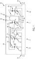
- FIG. 1 is a diagrammatic representation of a multi-speed transmission 100.
- Multi-speed transmission 100 includes an input member 102 and an output member 104. Each of input member 102 and output member 104 is rotatable relative to at least one stationary member 106.
- An exemplary input member 102 is an input shaft or other suitable rotatable component.
- An exemplary output member 104 is an output shaft or other suitable rotatable component.
- An exemplary stationary member 106 is a housing of multi-speed transmission 100. The housing may include several components coupled together.
- Multi-speed transmission 100 includes a plurality of planetary gearsets, illustratively a first planetary gearset 108, a second planetary gearset 110, a third planetary gearset 112, and a fourth planetary gearset 114.
- additional planetary gearsets may be included.
- first planetary gearset 108, second planetary gearset 110, third planetary gearset 112, and fourth planetary gearset 114 are illustrated as simple planetary gearsets, it is contemplated that compound planetary gearsets may be included in some embodiments.
- multi-speed transmission 100 is arranged as illustrated in FIG. 1 , with first planetary gearset 108 positioned between a first location or end 116 at which input member 102 enters stationary member 106 and second planetary gearset 110, second planetary gearset 110 is positioned between first planetary gearset 108 and third planetary gearset 112, third planetary gearset 112 is positioned between second planetary gearset 110 and fourth planetary gearset 114, and fourth planetary gearset 114 is positioned between third planetary gearset 112 and a second location or end 118 at which output member 104 exits stationary member 106.
- first planetary gearset 108, second planetary gearset 110, third planetary gearset 112, and fourth planetary gearset 114 are arranged in any order relative to location 116 and location 118.
- each of first planetary gearset 108, second planetary gearset 110, third planetary gearset 112, and fourth planetary gearset 114 are axially aligned.
- input member 102 and output member 104 are also axially aligned with first planetary gearset 108, second planetary gearset 110, third planetary gearset 112, and fourth planetary gearset 114.
- one or more of input member 102, output member 104, first planetary gearset 108, second planetary gearset 110, third planetary gearset 112, and fourth planetary gearset 114 are offset and not axially aligned with the remainder.
- First planetary gearset 108 includes a sun gear 120, a planet carrier 122 supporting a plurality of planet gears 124, and a ring gear 126.
- Second planetary gearset 110 includes a sun gear 130, a planet carrier 132 supporting a plurality of planet gears 134, and a ring gear 136.
- Third planetary gearset 112 includes a sun gear 140, a planet carrier 142 supporting a plurality of planet gears 144, and a ring gear 146.
- Fourth planetary gearset 114 includes a sun gear 150, a planet carrier 152 supporting a plurality of planet gears 154, and a ring gear 156.
- Multi-speed transmission 100 further includes a plurality of selective couplers, illustratively a first selective coupler 162, a second selective coupler 164, a third selective coupler 166, a fourth selective coupler 168, a fifth selective coupler 170, and a sixth selective coupler 172.
- first selective coupler 162 and second selective coupler 164 are brakes and third selective coupler 166, fourth selective coupler 168, fifth selective coupler 170, and sixth selective coupler 172 are clutches.
- the axial locations of the clutches and brakes relative to the plurality of planetary gearsets may be altered from the illustrated axial locations. In alternative embodiments, any number of clutches and brakes may be used.
- Multi-speed transmission 100 includes several components that are illustratively shown as being fixedly coupled together.
- Input member 102 is fixedly coupled to sun gear 120 of first planetary gearset 108 and sun gear 130 of second planetary gearset 110.
- Output member 104 is fixedly coupled to ring gear 156 of fourth planetary gearset 114.
- Ring gear 126 of first planetary gearset 108, ring gear 136 of second planetary gearset 110, and sun gear 150 of fourth planetary gearset 114 are fixedly coupled together.
- Planet carrier 122 of first planetary gearset 108 is fixedly coupled to ring gear 146 of third planetary gearset 112.
- one or more of the components fixedly coupled together are selectively coupled together through one or more selective couplers.
- Multi-speed transmission 100 may be described as having eight interconnectors.
- Input member 102 is a first interconnector that both provides input torque to multi-speed transmission 100 and fixedly couples sun gear 120 of first planetary gearset 108 to sun gear 130 of second planetary gearset 110.
- Input member 102 is further fixedly coupled to third selective coupler 166.
- Output member 104 is a second interconnector that provides output torque from multi-speed transmission 100.
- a third interconnector 180 fixedly couples ring gear 126 of first planetary gearset 108, ring gear 136 of second planetary gearset 110, and sun gear 150 of fourth planetary gearset 114 together.
- Third interconnector 180 is further fixedly coupled to fourth selective coupler 168.
- a fourth interconnector 182 fixedly couples planet carrier 122 of first planetary gearset 108 to ring gear 146 of third planetary gearset 112.
- a fifth interconnector 184 fixedly couples planet carrier 132 of second planetary gearset 110 to fifth selective coupler 170.
- a sixth interconnector 186 fixedly couples planet carrier 152 of fourth planetary gearset 114, third selective coupler 166, fifth selective coupler 170, and sixth selective coupler 172 together.
- a seventh interconnector 188 fixedly couples planet carrier 142 of third planetary gearset 112 to first selective coupler 162 and to fourth selective coupler 168.
- An eighth interconnector 190 fixedly couples sun gear 140 of third planetary gearset 112 to second selective coupler 164 and to sixth selective coupler 172.
- Multi-speed transmission 100 further includes several components that are illustratively shown as being selectively coupled together through selective couplers.
- First selective coupler 162 when engaged, fixedly couples planet carrier 142 of third planetary gearset 112 to stationary member 106.
- first selective coupler 162 When first selective coupler 162 is engaged, planet carrier 142 of third planetary gearset 112 and stationary member 106 are locked together.
- first selective coupler 162 is disengaged, planet carrier 142 of third planetary gearset 112 may rotate relative to stationary member 106.
- Second selective coupler 164 when engaged, fixedly couples sun gear 140 of third planetary gearset 112 to stationary member 106. When second selective coupler 164 is disengaged, sun gear 140 of third planetary gearset 112 may rotate relative to stationary member 106.
- Third selective coupler 166 when engaged, fixedly couples sun gear 120 of first planetary gearset 108 and sun gear 130 of second planetary gearset 110 to planet carrier 152 of fourth planetary gearset 114.
- planet carrier 152 of fourth planetary gearset 114 may rotate relative to sun gear 120 of first planetary gearset 108 and sun gear 130 of second planetary gearset 110.
- Fourth selective coupler 168 when engaged, fixedly couples planet carrier 142 of third planetary gearset 112 to third interconnector 180 and thus to ring gear 126 of first planetary gearset 108, ring gear 136 of second planetary gearset 110, and sun gear 150 of fourth planetary gearset 114.
- fourth selective coupler 168 When fourth selective coupler 168 is disengaged, planet carrier 142 of third planetary gearset 112 may rotate relative to third interconnector 180 and thus relative to ring gear 126 of first planetary gearset 108, ring gear 136 of second planetary gearset 110, and sun gear 150 of fourth planetary gearset 114.
- Fifth selective coupler 170 when engaged, fixedly couples planet carrier 132 of second planetary gearset 110 to planet carrier 152 of fourth planetary gearset 114.
- fifth selective coupler 170 when fifth selective coupler 170 is disengaged, planet carrier 132 of second planetary gearset 110 may rotate relative to planet carrier 152 of fourth planetary gearset 114.
- Sixth selective coupler 172 when engaged, fixedly couples planet carrier 152 of fourth planetary gearset 114 to sun gear 140 of third planetary gearset 112. When sixth selective coupler 172 is disengaged, planet carrier 152 of fourth planetary gearset 114 may rotate relative to sun gear 140 of third planetary gearset 112.
- first selective coupler 162 By engaging various combinations of first selective coupler 162, second selective coupler 164, third selective coupler 166, fourth selective coupler 168, fifth selective coupler 170, and sixth selective coupler 172, additional components of multi-speed transmission 100 may be fixedly coupled together.
- the plurality of planetary gearsets and the plurality of selective couplers of multi-speed transmission 100 may be interconnected in various arrangements to provide torque from input member 102 to output member 104 in at least nine forward gear or speed ratios and one reverse gear or speed ratio.
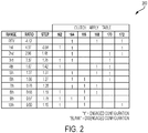
- an exemplary truth table 200 is shown that provides the state of each of first selective coupler 162, second selective coupler 164, third selective coupler 166, fourth selective coupler 168, fifth selective coupler 170, and sixth selective coupler 172 for ten different forward gear or speed ratios and one reverse gear or speed ratio.
- Each row corresponds to a given interconnection arrangement for transmission 100.
- the first column provides the gear range (reverse and 1 st -10 th forward gears).
- the second column provides the gear ratio between the input member 102 and the output member 104.
- the third column provides the gear step.
- the six rightmost columns illustrate which ones of the selective couplers 162-172 are engaged ("1" indicates engaged) and which ones of selective couplers 162-172 are disengaged ("(blank)" indicates disengaged).
- FIG. 2 is only one example of any number of truth tables possible for achieving at least nine forward ratios and one reverse ratio.
- the illustrated reverse ratio (Rev) is achieved by having second selective coupler 164, fourth selective coupler 168, and sixth selective coupler 172 in an engaged configuration and first selective coupler 162, third selective coupler 166, and fifth selective coupler 170 in a disengaged configuration.
- first selective coupler 162, second selective coupler 164, third selective coupler 166, fourth selective coupler 168, fifth selective coupler 170, and sixth selective coupler 172 are in the disengaged configuration.
- One or more of first selective coupler 162, second selective coupler 164, third selective coupler 166, fourth selective coupler 168, fifth selective coupler 170, and sixth selective coupler 172 may remain engaged in neutral (Neu) as long as the combination of first selective coupler 162, second selective coupler 164, third selective coupler 166, fourth selective coupler 168, fifth selective coupler 170, and sixth selective coupler 172 does not transmit torque from input member 102 to output member 104.
- a first forward ratio (shown as 1st) in truth table 200 of FIG. 2 is achieved by having first selective coupler 162, second selective coupler 164, and sixth selective coupler 172 in an engaged configuration and third selective coupler 166, fourth selective coupler 168, and fifth selective coupler 170 in a disengaged configuration.
- a second or subsequent forward ratio (shown as 2nd) in truth table 200 of FIG. 2 is achieved by having second selective coupler 164, fifth selective coupler 170, and sixth selective coupler 172 in an engaged configuration and first selective coupler 162, third selective coupler 166, and fourth selective coupler 168 in a disengaged configuration. Therefore, when transitioning between the first forward ratio and the second forward ratio, first selective coupler 162 is placed in the disengaged configuration and fifth selective coupler 170 is placed in the engaged configuration.
- a third or subsequent forward ratio (shown as 3rd) in truth table 200 of FIG. 2 is achieved by having first selective coupler 162, second selective coupler 164, and fifth selective coupler 170 in an engaged configuration and third selective coupler 166, fourth selective coupler 168, and sixth selective coupler 172 in a disengaged configuration. Therefore, when transitioning between the second forward ratio and the third forward ratio, sixth selective coupler 172 is placed in the disengaged configuration and first selective coupler 162 is placed in the engaged configuration.
- a fourth or subsequent forward ratio (shown as 4th) in truth table 200 of FIG. 2 is achieved by having first selective coupler 162, fourth selective coupler 168, and fifth selective coupler 170 in an engaged configuration and second selective coupler 164, third selective coupler 166, and sixth selective coupler 172 in a disengaged configuration. Therefore, when transitioning between the third forward ratio and the fourth forward ratio, second selective coupler 164 is placed in the disengaged configuration and fourth selective coupler 168 is placed in the engaged configuration.
- a fifth or subsequent forward ratio (shown as 5th) in truth table 200 of FIG. 2 is achieved by having second selective coupler 164, fourth selective coupler 168, and fifth selective coupler 170 in an engaged configuration and first selective coupler 162, third selective coupler 166, and sixth selective coupler 172 in a disengaged configuration. Therefore, when transitioning between the fourth forward ratio and the fifth forward ratio, first selective coupler 162 is placed in the disengaged configuration and second selective coupler 164 is placed in the engaged configuration.
- a sixth or subsequent forward ratio (shown as 6th) in truth table 200 of FIG. 2 is achieved by having second selective coupler 164, third selective coupler 166, and fifth selective coupler 170 in an engaged configuration and first selective coupler 162, fourth selective coupler 168, and sixth selective coupler 172 in a disengaged configuration. Therefore, when transitioning between the fifth forward ratio and the sixth forward ratio, fourth selective coupler 168 is placed in the disengaged configuration and third selective coupler 166 is placed in the engaged configuration.
- a seventh or subsequent forward ratio (shown as 7th) in truth table 200 of FIG. 2 is achieved by having second selective coupler 164, third selective coupler 166, and fourth selective coupler 168 in an engaged configuration and first selective coupler 162, fifth selective coupler 170, and sixth selective coupler 172 in a disengaged configuration. Therefore, when transitioning between the sixth forward ratio and the seventh forward ratio, fifth selective coupler 170 is placed in the disengaged configuration and fourth selective coupler 168 is placed in the engaged configuration.
- An eighth or subsequent forward ratio (shown as 8th) in truth table 200 of FIG. 2 is achieved by having first selective coupler 162, third selective coupler 166, and fourth selective coupler 168 in an engaged configuration and second selective coupler 164, fifth selective coupler 170, and sixth selective coupler 172 in a disengaged configuration. Therefore, when transitioning between the seventh forward ratio and the eighth forward ratio, second selective coupler 164 is placed in the disengaged configuration and first selective coupler 162 is placed in the engaged configuration.
- a ninth or subsequent forward ratio (shown as 9th) in truth table 200 of FIG. 2 is achieved by having first selective coupler 162, second selective coupler 164, and third selective coupler 166 in an engaged configuration and fourth selective coupler 168, fifth selective coupler 170, and sixth selective coupler 172 in a disengaged configuration. Therefore, when transitioning between the eighth forward ratio and the ninth forward ratio, fourth selective coupler 168 is placed in the disengaged configuration and second selective coupler 164 is placed in the engaged configuration.
- a tenth or subsequent forward ratio (shown as 10th) in truth table 200 of FIG. 2 is achieved by having first selective coupler 162, third selective coupler 166, and sixth selective coupler 172 in an engaged configuration and second selective coupler 164, fourth selective coupler 168, and fifth selective coupler 170 in a disengaged configuration. Therefore, when transitioning between the ninth forward ratio and the tenth forward ratio, second selective coupler 164 is placed in the disengaged configuration and sixth selective coupler 172 is placed in the engaged configuration.
- multi-speed transmission 250 is illustrated.
- the kinematics of multi-speed transmission 250 are generally identical to multi-speed transmission 100 with the following differences.
- interconnector 252 of multi-speed transmission 250 fixedly couples sun gear 140 of third planetary gearset 112 to second selective coupler 164, but not also to the sixth selective coupler as accomplished by eighth interconnector 190 of multi-speed transmission 100.
- sixth selective coupler 254 of multi-speed transmission 250 when engaged, fixedly couples planet carrier 152 of fourth planetary gearset 114 to stationary member 106, not to sun gear 140 of third planetary gearset 112 as accomplished by sixth selective coupler 172 of multi-speed transmission 100.
- Multi-speed transmission 250 has an equal number of clutches, third selective coupler 166, fourth selective coupler 168, and fifth selective coupler 170, and brakes, first selective coupler 162, second selective coupler 164, and sixth selective coupler 254.
- the plurality of planetary gearsets and the plurality of selective couplers of multi-speed transmission 250 may be interconnected in various arrangements to provide torque from input member 102 to output member 104 in at least nine forward gear or speed ratios and one reverse gear or speed ratio.
- an exemplary truth table 260 is shown that provides the state of each of first selective coupler 162, second selective coupler 164, third selective coupler 166, fourth selective coupler 168, fifth selective coupler 170, and sixth selective coupler 254 for nine different forward gear or speed ratios and one reverse gear or speed ratio.
- Each row corresponds to a given interconnection arrangement for transmission 250.
- the first column provides the gear range (reverse and 1 st -9 th forward gears).
- the second column provides the gear ratio between the input member 102 and the output member 104.
- the third column provides the gear step.
- the six rightmost columns illustrate which ones of the selective couplers 162-170 and 254 are engaged ("1" indicates engaged) and which ones of selective couplers 162-170 and 254 are disengaged ("(blank)" indicates disengaged).
- FIG. 4 is only one example of any number of truth tables possible for achieving at least nine forward ratios and one reverse ratio.
- the illustrated reverse ratio (Rev) is achieved by having second selective coupler 164, fourth selective coupler 168, and sixth selective coupler 254 in an engaged configuration and first selective coupler 162, third selective coupler 166, and fifth selective coupler 170 in a disengaged configuration.
- first selective coupler 162, second selective coupler 164, third selective coupler 166, fourth selective coupler 168, fifth selective coupler 170, and sixth selective coupler 254 are in the disengaged configuration.
- One or more of first selective coupler 162, second selective coupler 164, third selective coupler 166, fourth selective coupler 168, fifth selective coupler 170, and sixth selective coupler 254 may remain engaged in neutral (Neu) as long as the combination of first selective coupler 162, second selective coupler 164, third selective coupler 166, fourth selective coupler 168, fifth selective coupler 170, and sixth selective coupler 254 does not transmit torque from input member 102 to output member 104.
- a first forward ratio (shown as 1st) in truth table 260 of FIG. 4 is achieved by having first selective coupler 162, second selective coupler 164, and sixth selective coupler 254 in an engaged configuration and third selective coupler 166, fourth selective coupler 168, and fifth selective coupler 170 in a disengaged configuration.
- a second or subsequent forward ratio (shown as 2nd) in truth table 260 of FIG. 4 is achieved by having second selective coupler 164, fifth selective coupler 170, and sixth selective coupler 254 in an engaged configuration and first selective coupler 162, third selective coupler 166, and fourth selective coupler 168 in a disengaged configuration. Therefore, when transitioning between the first forward ratio and the second forward ratio, first selective coupler 162 is placed in the disengaged configuration and fifth selective coupler 170 is placed in the engaged configuration.
- a third or subsequent forward ratio (shown as 3rd) in truth table 260 of FIG. 4 is achieved by having first selective coupler 162, second selective coupler 164, and fifth selective coupler 170 in an engaged configuration and third selective coupler 166, fourth selective coupler 168, and sixth selective coupler 254 in a disengaged configuration. Therefore, when transitioning between the second forward ratio and the third forward ratio, sixth selective coupler 254 is placed in the disengaged configuration and first selective coupler 162 is placed in the engaged configuration.
- a fourth or subsequent forward ratio (shown as 4th) in truth table 260 of FIG. 4 is achieved by having first selective coupler 162, fourth selective coupler 168, and fifth selective coupler 170 in an engaged configuration and second selective coupler 164, third selective coupler 166, and sixth selective coupler 254 in a disengaged configuration. Therefore, when transitioning between the third forward ratio and the fourth forward ratio, second selective coupler 164 is placed in the disengaged configuration and fourth selective coupler 168 is placed in the engaged configuration.
- a fifth or subsequent forward ratio (shown as 5th) in truth table 260 of FIG. 4 is achieved by having second selective coupler 164, fourth selective coupler 168, and fifth selective coupler 170 in an engaged configuration and first selective coupler 162, third selective coupler 166, and sixth selective coupler 254 in a disengaged configuration. Therefore, when transitioning between the fourth forward ratio and the fifth forward ratio, first selective coupler 162 is placed in the disengaged configuration and second selective coupler 164 is placed in the engaged configuration.
- a sixth or subsequent forward ratio (shown as 6th) in truth table 260 of FIG. 4 is achieved by having second selective coupler 164, third selective coupler 166, and fifth selective coupler 170 in an engaged configuration and first selective coupler 162, fourth selective coupler 168, and sixth selective coupler 254 in a disengaged configuration. Therefore, when transitioning between the fifth forward ratio and the sixth forward ratio, fourth selective coupler 168 is placed in the disengaged configuration and third selective coupler 166 is placed in the engaged configuration.
- a seventh or subsequent forward ratio (shown as 7th) in truth table 260 of FIG. 4 is achieved by having second selective coupler 164, third selective coupler 166, and fourth selective coupler 168 in an engaged configuration and first selective coupler 162, fifth selective coupler 170, and sixth selective coupler 254 in a disengaged configuration. Therefore, when transitioning between the sixth forward ratio and the seventh forward ratio, fifth selective coupler 170 is placed in the disengaged configuration and fourth selective coupler 168 is placed in the engaged configuration.
- An eighth or subsequent forward ratio (shown as 8th) in truth table 260 of FIG. 4 is achieved by having first selective coupler 162, third selective coupler 166, and fourth selective coupler 168 in an engaged configuration and second selective coupler 164, fifth selective coupler 170, and sixth selective coupler 254 in a disengaged configuration. Therefore, when transitioning between the seventh forward ratio and the eighth forward ratio, second selective coupler 164 is placed in the disengaged configuration and first selective coupler 162 is placed in the engaged configuration.
- a ninth or subsequent forward ratio (shown as 9th) in truth table 260 of FIG. 4 is achieved by having first selective coupler 162, second selective coupler 164, and third selective coupler 166 in an engaged configuration and fourth selective coupler 168, fifth selective coupler 170, and sixth selective coupler 254 in a disengaged configuration. Therefore, when transitioning between the eighth forward ratio and the ninth forward ratio, fourth selective coupler 168 is placed in the disengaged configuration and second selective coupler 164 is placed in the engaged configuration.
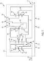
- FIG. 5 is a diagrammatic representation of a multi-speed transmission 300.
- Multi-speed transmission 300 includes an input member 302 and an output member 304. Each of input member 302 and output member 304 is rotatable relative to at least one stationary member 306.
- An exemplary input member 302 is an input shaft or other suitable rotatable component.
- An exemplary output member 304 is an output shaft or other suitable rotatable component.
- An exemplary stationary member 306 is a housing of multi-speed transmission 300. The housing may include several components coupled together.
- Multi-speed transmission 300 includes a plurality of planetary gearsets, illustratively a first planetary gearset 308, a second planetary gearset 310, a third planetary gearset 312, and a fourth planetary gearset 314. In one embodiment, additional planetary gearsets may be included. Further, although first planetary gearset 308, second planetary gearset 310, third planetary gearset 312, and fourth planetary gearset 314 are illustrated as simple planetary gearsets, it is contemplated that compound planetary gearsets may be included in some embodiments.
- multi-speed transmission 300 is arranged as illustrated in FIG. 5 , with first planetary gearset 308 positioned between a first location or end 316 at which input member 302 enters stationary member 306 and second planetary gearset 310, second planetary gearset 310 is positioned between first planetary gearset 308 and third planetary gearset 312, third planetary gearset 312 is positioned between second planetary gearset 310 and fourth planetary gearset 314, and fourth planetary gearset 314 is positioned between third planetary gearset 312 and a second location or end 318 at which output member 304 exits stationary member 306.
- first planetary gearset 308, second planetary gearset 310, third planetary gearset 312, and fourth planetary gearset 314 are arranged in any order relative to location 316 and location 318.
- each of first planetary gearset 308, second planetary gearset 310, third planetary gearset 312, and fourth planetary gearset 314 are axially aligned.
- input member 302 and output member 304 are also axially aligned with first planetary gearset 308, second planetary gearset 310, third planetary gearset 312, and fourth planetary gearset 314.
- one or more of input member 302, output member 304, first planetary gearset 308, second planetary gearset 310, third planetary gearset 312, and fourth planetary gearset 314 are offset and not axially aligned with the remainder.
- First planetary gearset 308 includes a sun gear 320, a planet carrier 322 supporting a plurality of planet gears 324, and a ring gear 326.
- Second planetary gearset 310 includes a sun gear 330, a planet carrier 332 supporting a plurality of planet gears 334, and a ring gear 336.
- Third planetary gearset 312 includes a sun gear 340, a planet carrier 342 supporting a plurality of planet gears 344, and a ring gear 346.
- Fourth planetary gearset 314 includes a sun gear 350, a planet carrier 352 supporting a plurality of planet gears 354, and a ring gear 356.
- Multi-speed transmission 300 further includes a plurality of selective couplers, illustratively a first selective coupler 362, a second selective coupler 364, a third selective coupler 366, a fourth selective coupler 368, a fifth selective coupler 370, and a sixth selective coupler 372.
- first selective coupler 362 and second selective coupler 364 are brakes and third selective coupler 366, fourth selective coupler 368, fifth selective coupler 370, and sixth selective coupler 372 are clutches.
- the axial locations of the clutches and brakes relative to the plurality of planetary gearsets may be altered from the illustrated axial locations. In alternative embodiments, any number of clutches and brakes may be used.
- Multi-speed transmission 300 includes several components that are illustratively shown as being fixedly coupled together.
- Input member 302 is fixedly coupled to sun gear 320 of first planetary gearset 308.
- Output member 304 is fixedly coupled to ring gear 356 of fourth planetary gearset 314.
- Ring gear 326 of first planetary gearset 308, sun gear 330 of second planetary gearset 310, and sun gear 350 of fourth planetary gearset 314 are fixedly coupled together.
- Planet carrier 322 of first planetary gearset 308 is fixedly coupled to ring gear 336 of second planetary gearset 310.
- Planet carrier 332 of second planetary gearset 310 is fixedly coupled to ring gear 346 of third planetary gearset 312.
- one or more of the components fixedly coupled together are selectively coupled together through one or more selective couplers.
- Multi-speed transmission 300 may be described as having eight interconnectors.
- Input member 302 is a first interconnector that both provides input torque to multi-speed transmission 300 and fixedly couples sun gear 320 of first planetary gearset 308 to third selective coupler 366.
- Output member 304 is a second interconnector that provides output torque from multi-speed transmission 300.
- a third interconnector 380 fixedly couples ring gear 326 of first planetary gearset 308, sun gear 330 of second planetary gearset 310, and sun gear 350 of fourth planetary gearset 314 together.
- Third interconnector 380 is further fixedly coupled to fourth selective coupler 368.
- a fourth interconnector 382 fixedly couples planet carrier 322 of first planetary gearset 308 to ring gear 336 of second planetary gearset 310.
- Fourth interconnector 382 is further fixedly coupled to fifth selective coupler 370.
- a fifth interconnector 384 fixedly couples planet carrier 332 of second planetary gearset 310 to ring gear 346 of third planetary gearset 312.
- a sixth interconnector 386 fixedly couples planet carrier 352 of fourth planetary gearset 314 to third selective coupler 366 and to sixth selective coupler 372.
- a seventh interconnector 388 fixedly couples planet carrier 342 of third planetary gearset 312 to first selective coupler 362 and to fourth selective coupler 368.
- An eighth interconnector 390 fixedly couples sun gear 340 of third planetary gearset 312 to second selective coupler 364 and to sixth selective coupler 372.
- Multi-speed transmission 300 further includes several components that are illustratively shown as being selectively coupled together through selective couplers.
- First selective coupler 362 when engaged, fixedly couples planet carrier 342 of third planetary gearset 312 to stationary member 306.
- planet carrier 342 of third planetary gearset 312 may rotate relative to stationary member 306.
- Second selective coupler 364 when engaged, fixedly couples sun gear 340 of third planetary gearset 312 to stationary member 306.
- sun gear 340 of third planetary gearset 312 may rotate relative to stationary member 306.
- Third selective coupler 366 when engaged, fixedly couples sun gear 320 of first planetary gearset 308 to planet carrier 352 of fourth planetary gearset 314. When third selective coupler 366 is disengaged, planet carrier 352 of fourth planetary gearset 314 may rotate relative to sun gear 320 of first planetary gearset 308.
- Fourth selective coupler 368 when engaged, fixedly couples ring gear 326 of first planetary gearset 308, sun gear 330 of second planetary gearset 310, and sun gear 350 of fourth planetary gearset 314 to planet carrier 342 of third planetary gearset 312.
- planet carrier 342 of third planetary gearset 312 may rotate relative to ring gear 326 of first planetary gearset 308, sun gear 330 of second planetary gearset 310, and sun gear 350 of fourth planetary gearset 314.
- Fifth selective coupler 370 when engaged, fixedly couples planet carrier 322 of first planetary gearset 308 to planet carrier 352 of fourth planetary gearset 314.
- fifth selective coupler 370 when fifth selective coupler 370 is disengaged, planet carrier 322 of first planetary gearset 308 may rotate relative to planet carrier 352 of fourth planetary gearset 314.
- Sixth selective coupler 372 when engaged, fixedly couples planet carrier 352 of fourth planetary gearset 314 to sun gear 340 of third planetary gearset 312 and to second selective coupler 364.
- sixth selective coupler 372 When sixth selective coupler 372 is disengaged, planet carrier 352 of fourth planetary gearset 314 may rotate relative to sun gear 340 of third planetary gearset 312.
- first selective coupler 362 By engaging various combinations of first selective coupler 362, second selective coupler 364, third selective coupler 366, fourth selective coupler 368, fifth selective coupler 370, and sixth selective coupler 372, additional components of multi-speed transmission 300 may be fixedly coupled together.
- the plurality of planetary gearsets and the plurality of selective couplers of multi-speed transmission 300 may be interconnected in various arrangements to provide torque from input member 302 to output member 304 in at least nine forward gear or speed ratios and one reverse gear or speed ratio.
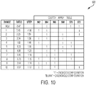
- an exemplary truth table 400 is shown that provides the state of each of first selective coupler 362, second selective coupler 364, third selective coupler 366, fourth selective coupler 368, fifth selective coupler 370, and sixth selective coupler 372 for ten different forward gear or speed ratios and one reverse gear or speed ratio.
- Each row corresponds to a given interconnection arrangement for transmission 300.
- the first column provides the gear range (reverse and 1 st -10 th forward gears).
- the second column provides the gear ratio between the input member 302 and the output member 304.
- the third column provides the gear step.
- the six rightmost columns illustrate which ones of the selective couplers 362-372 are engaged ("1" indicates engaged) and which ones of selective couplers 362-372 are disengaged ("(blank)" indicates disengaged).
- FIG. 4 is only one example of any number of truth tables possible for achieving at least nine forward ratios and one reverse ratio.
- the illustrated reverse ratio (Rev) is achieved by having second selective coupler 364, fourth selective coupler 368, and sixth selective coupler 372 in an engaged configuration and first selective coupler 362, third selective coupler 366, and fifth selective coupler 370 in a disengaged configuration.
- first selective coupler 362, second selective coupler 364, third selective coupler 366, fourth selective coupler 368, fifth selective coupler 370, and sixth selective coupler 372 are in the disengaged configuration.
- One or more of first selective coupler 362, second selective coupler 364, third selective coupler 366, fourth selective coupler 368, fifth selective coupler 370, and sixth selective coupler 372 may remain engaged in neutral (Neu) as long as the combination of first selective coupler 362, second selective coupler 364, third selective coupler 366, fourth selective coupler 368, fifth selective coupler 370, and sixth selective coupler 372 does not transmit torque from input member 302 to output member 304.
- a first forward ratio (shown as 1st) in truth table 400 of FIG. 6 is achieved by having first selective coupler 362, second selective coupler 364, and sixth selective coupler 372 in an engaged configuration and third selective coupler 366, fourth selective coupler 368, and fifth selective coupler 370 in a disengaged configuration.
- a second or subsequent forward ratio (shown as 2nd) in truth table 400 of FIG. 6 is achieved by having second selective coupler 364, fifth selective coupler 370, and sixth selective coupler 372 in an engaged configuration and first selective coupler 362, third selective coupler 366, and fourth selective coupler 368 in a disengaged configuration. Therefore, when transitioning between the first forward ratio and the second forward ratio, first selective coupler 362 is placed in the disengaged configuration and fifth selective coupler 370 is placed in the engaged configuration.
- a third or subsequent forward ratio (shown as 3rd) in truth table 400 of FIG. 6 is achieved by having first selective coupler 362, second selective coupler 364, and fifth selective coupler 370 in an engaged configuration and third selective coupler 366, fourth selective coupler 368, and sixth selective coupler 372 in a disengaged configuration. Therefore, when transitioning between the second forward ratio and the third forward ratio, sixth selective coupler 372 is placed in the disengaged configuration and first selective coupler 362 is placed in the engaged configuration.
- a fourth or subsequent forward ratio (shown as 4th) in truth table 400 of FIG. 6 is achieved by having first selective coupler 362, fourth selective coupler 368, and fifth selective coupler 370 in an engaged configuration and second selective coupler 364, third selective coupler 366, and sixth selective coupler 372 in a disengaged configuration. Therefore, when transitioning between the third forward ratio and the fourth forward ratio, second selective coupler 364 is placed in the disengaged configuration and fourth selective coupler 368 is placed in the engaged configuration.
- a fifth or subsequent forward ratio (shown as 5th) in truth table 400 of FIG. 6 is achieved by having second selective coupler 364, fourth selective coupler 368, and fifth selective coupler 370 in an engaged configuration and first selective coupler 362, third selective coupler 366, and sixth selective coupler 372 in a disengaged configuration. Therefore, when transitioning between the fourth forward ratio and the fifth forward ratio, first selective coupler 362 is placed in the disengaged configuration and second selective coupler 364 is placed in the engaged configuration.
- a sixth or subsequent forward ratio (shown as 6th) in truth table 400 of FIG. 6 is achieved by having third selective coupler 366, fourth selective coupler 368, and fifth selective coupler 370 in an engaged configuration and first selective coupler 362, second selective coupler 364, and sixth selective coupler 372 in a disengaged configuration. Therefore, when transitioning between the fifth forward ratio and the sixth forward ratio, second selective coupler 364 is placed in the disengaged configuration and third selective coupler 366 is placed in the engaged configuration.
- a seventh or subsequent forward ratio (shown as 7th) in truth table 400 of FIG. 6 is achieved by having second selective coupler 364, third selective coupler 366, and fourth selective coupler 368 in an engaged configuration and first selective coupler 362, fifth selective coupler 370, and sixth selective coupler 372 in a disengaged configuration. Therefore, when transitioning between the sixth forward ratio and the seventh forward ratio, fifth selective coupler 370 is placed in the disengaged configuration and second selective coupler 364 is placed in the engaged configuration.
- An eighth or subsequent forward ratio (shown as 8th) in truth table 400 of FIG. 6 is achieved by having first selective coupler 362, third selective coupler 366, and fourth selective coupler 368 in an engaged configuration and second selective coupler 364, fifth selective coupler 370, and sixth selective coupler 372 in a disengaged configuration. Therefore, when transitioning between the seventh forward ratio and the eighth forward ratio, second selective coupler 364 is placed in the disengaged configuration and first selective coupler 362 is placed in the engaged configuration.
- a ninth or subsequent forward ratio (shown as 9th) in truth table 400 of FIG. 6 is achieved by having first selective coupler 362, second selective coupler 364, and third selective coupler 366 in an engaged configuration and fourth selective coupler 368, fifth selective coupler 370, and sixth selective coupler 372 in a disengaged configuration. Therefore, when transitioning between the eighth forward ratio and the ninth forward ratio, fourth selective coupler 368 is placed in the disengaged configuration and second selective coupler 364 is placed in the engaged configuration.
- a tenth or subsequent forward ratio (shown as 10th) in truth table 400 of FIG. 6 is achieved by having first selective coupler 362, third selective coupler 366, and sixth selective coupler 372 in an engaged configuration and second selective coupler 364, fourth selective coupler 368, and fifth selective coupler 370 in a disengaged configuration. Therefore, when transitioning between the ninth forward ratio and the tenth forward ratio, second selective coupler 364 is placed in the disengaged configuration and sixth selective coupler 372 is placed in the engaged configuration.
- FIG. 7 another exemplary multi-speed transmission 450 is illustrated.
- the kinematics of multi-speed transmission 450 are generally identical to multi-speed transmission 300 with the following differences.
- sixth selective coupler 454 of multi-speed transmission 450 when engaged, fixedly couples planet carrier 352 of fourth planetary gearset 314 to stationary member 306, not to sun gear 340 of third planetary gearset 312 as accomplished by sixth selective coupler 372 of multi-speed transmission 300.
- planet carrier 352 of fourth planetary gearset 314 may rotate relative to stationary member 306.
- interconnector 452 of multi-speed transmission 450 fixedly couples sun gear 340 of third planetary gearset 312 to second selective coupler 364, but not also to the sixth selective coupler as accomplished by eighth interconnector 390 of multi-speed transmission 300.
- Multi-speed transmission 450 has an equal number of clutches, third selective coupler 366, fourth selective coupler 368, and fifth selective coupler 370, and brakes, first selective coupler 362, second selective coupler 364, and sixth selective coupler 454.
- the plurality of planetary gearsets and the plurality of selective couplers of multi-speed transmission 450 may be interconnected in various arrangements to provide torque from input member 302 to output member 304 in at least nine forward gear or speed ratios and one reverse gear or speed ratio.
- an exemplary truth table 460 is shown that provides the state of each of first selective coupler 362, second selective coupler 364, third selective coupler 366, fourth selective coupler 368, fifth selective coupler 370, and sixth selective coupler 454 for nine different forward gear or speed ratios and one reverse gear or speed ratio.
- Each row corresponds to a given interconnection arrangement for transmission 450.
- the first column provides the gear range (reverse and 1 st -9 th forward gears).
- the second column provides the gear ratio between the input member 302 and the output member 304.
- the third column provides the gear step.
- the six rightmost columns illustrate which ones of the selective couplers 362-370 and 454 are engaged ("1" indicates engaged) and which ones of selective couplers 362-370 and 454 are disengaged ("(blank)" indicates disengaged).
- FIG. 8 is only one example of any number of truth tables possible for achieving at least nine forward ratios and one reverse ratio.
- the illustrated reverse ratio (Rev) is achieved by having second selective coupler 364, fourth selective coupler 368, and sixth selective coupler 454 in an engaged configuration and first selective coupler 362, third selective coupler 366, and fifth selective coupler 370 in a disengaged configuration.
- first selective coupler 362, second selective coupler 364, third selective coupler 366, fourth selective coupler 368, fifth selective coupler 370, and sixth selective coupler 454 are in the disengaged configuration.
- One or more of first selective coupler 362, second selective coupler 364, third selective coupler 366, fourth selective coupler 368, fifth selective coupler 370, and sixth selective coupler 454 may remain engaged in neutral (Neu) as long as the combination of first selective coupler 362, second selective coupler 364, third selective coupler 366, fourth selective coupler 368, fifth selective coupler 370, and sixth selective coupler 454 does not transmit torque from input member 302 to output member 304.
- a first forward ratio (shown as 1st) in truth table 460 of FIG. 8 is achieved by having first selective coupler 362, second selective coupler 364, and sixth selective coupler 454 in an engaged configuration and third selective coupler 366, fourth selective coupler 368, and fifth selective coupler 370 in a disengaged configuration.
- a second or subsequent forward ratio (shown as 2nd) in truth table 460 of FIG. 8 is achieved by having second selective coupler 364, fifth selective coupler 370, and sixth selective coupler 454 in an engaged configuration and first selective coupler 362, third selective coupler 366, and fourth selective coupler 368 in a disengaged configuration. Therefore, when transitioning between the first forward ratio and the second forward ratio, first selective coupler 362 is placed in the disengaged configuration and fifth selective coupler 370 is placed in the engaged configuration.
- a third or subsequent forward ratio (shown as 3rd) in truth table 460 of FIG. 8 is achieved by having first selective coupler 362, second selective coupler 364, and fifth selective coupler 370 in an engaged configuration and third selective coupler 366, fourth selective coupler 368, and sixth selective coupler 454 in a disengaged configuration. Therefore, when transitioning between the second forward ratio and the third forward ratio, sixth selective coupler 454 is placed in the disengaged configuration and first selective coupler 362 is placed in the engaged configuration.
- a fourth or subsequent forward ratio (shown as 4th) in truth table 460 of FIG. 8 is achieved by having first selective coupler 362, fourth selective coupler 368, and fifth selective coupler 370 in an engaged configuration and second selective coupler 364, third selective coupler 366, and sixth selective coupler 454 in a disengaged configuration. Therefore, when transitioning between the third forward ratio and the fourth forward ratio, second selective coupler 364 is placed in the disengaged configuration and fourth selective coupler 368 is placed in the engaged configuration.
- a fifth or subsequent forward ratio (shown as 5th) in truth table 460 of FIG. 8 is achieved by having second selective coupler 364, fourth selective coupler 368, and fifth selective coupler 370 in an engaged configuration and first selective coupler 362, third selective coupler 366, and sixth selective coupler 454 in a disengaged configuration. Therefore, when transitioning between the fourth forward ratio and the fifth forward ratio, first selective coupler 362 is placed in the disengaged configuration and second selective coupler 364 is placed in the engaged configuration.
- a sixth or subsequent forward ratio (shown as 6th) in truth table 460 of FIG. 8 is achieved by having third selective coupler 366, fourth selective coupler 368, and fifth selective coupler 370 in an engaged configuration and first selective coupler 362, second selective coupler 364, and sixth selective coupler 454 in a disengaged configuration. Therefore, when transitioning between the fifth forward ratio and the sixth forward ratio, second selective coupler 364 is placed in the disengaged configuration and third selective coupler 366 is placed in the engaged configuration.
- a seventh or subsequent forward ratio (shown as 7th) in truth table 460 of FIG. 8 is achieved by having second selective coupler 364, third selective coupler 366, and fourth selective coupler 368 in an engaged configuration and first selective coupler 362, fifth selective coupler 370, and sixth selective coupler 454 in a disengaged configuration. Therefore, when transitioning between the sixth forward ratio and the seventh forward ratio, fifth selective coupler 370 is placed in the disengaged configuration and second selective coupler 364 is placed in the engaged configuration.
- An eighth or subsequent forward ratio (shown as 8th) in truth table 460 of FIG. 8 is achieved by having first selective coupler 362, third selective coupler 366, and fourth selective coupler 368 in an engaged configuration and second selective coupler 364, fifth selective coupler 370, and sixth selective coupler 454 in a disengaged configuration. Therefore, when transitioning between the seventh forward ratio and the eighth forward ratio, second selective coupler 364 is placed in the disengaged configuration and first selective coupler 362 is placed in the engaged configuration.
- a ninth or subsequent forward ratio (shown as 9th) in truth table 460 of FIG. 8 is achieved by having first selective coupler 362, second selective coupler 364, and third selective coupler 366 in an engaged configuration and fourth selective coupler 368, fifth selective coupler 370, and sixth selective coupler 454 in a disengaged configuration. Therefore, when transitioning between the eighth forward ratio and the ninth forward ratio, fourth selective coupler 368 is placed in the disengaged configuration and second selective coupler 364 is placed in the engaged configuration.
- FIG. 9 is a diagrammatic representation of a multi-speed transmission 500.
- Multi-speed transmission 500 includes an input member 502 and an output member 504. Each of input member 502 and output member 504 is rotatable relative to at least one stationary member 506.
- An exemplary input member 502 is an input shaft or other suitable rotatable component.
- An exemplary output member 504 is an output shaft or other suitable rotatable component.
- An exemplary stationary member 506 is a housing of multi-speed transmission 500. The housing may include several components coupled together.
- Multi-speed transmission 500 includes a plurality of planetary gearsets, illustratively a first planetary gearset 508, a second planetary gearset 510, a third planetary gearset 512, and a fourth planetary gearset 514.
- additional planetary gearsets may be included.
- first planetary gearset 508, second planetary gearset 510, third planetary gearset 512, and fourth planetary gearset 514 are illustrated as simple planetary gearsets, it is contemplated that compound planetary gearsets may be included in some embodiments.
- multi-speed transmission 500 is arranged as illustrated in FIG. 9 , with first planetary gearset 508 positioned between a first location or end 516 at which input member 502 enters stationary member 506 and second planetary gearset 510, second planetary gearset 510 is positioned between first planetary gearset 508 and third planetary gearset 512, third planetary gearset 512 is positioned between second planetary gearset 510 and fourth planetary gearset 514, and fourth planetary gearset 514 is positioned between third planetary gearset 512 and a second location or end 518 at which output member 504 exits stationary member 506.
- first planetary gearset 508, second planetary gearset 510, third planetary gearset 512, and fourth planetary gearset 514 are arranged in any order relative to location 516 and location 518.
- each of first planetary gearset 508, second planetary gearset 510, third planetary gearset 512, and fourth planetary gearset 514 are axially aligned.
- input member 502 and output member 504 are also axially aligned with first planetary gearset 508, second planetary gearset 510, third planetary gearset 512, and fourth planetary gearset 514.
- one or more of input member 502, output member 504, first planetary gearset 508, second planetary gearset 510, third planetary gearset 512, and fourth planetary gearset 514 are offset and not axially aligned with the remainder.
- First planetary gearset 508 includes a sun gear 520, a planet carrier 522 supporting a plurality of planet gears 524, and a ring gear 526.
- Second planetary gearset 510 includes a sun gear 530, a planet carrier 532 supporting a plurality of planet gears 534, and a ring gear 536.
- Third planetary gearset 512 includes a sun gear 540, a planet carrier 542 supporting a plurality of planet gears 544, and a ring gear 546.
- Fourth planetary gearset 514 includes a sun gear 550, a planet carrier 552 supporting a plurality of planet gears 554, and a ring gear 556.
- Multi-speed transmission 500 further includes a plurality of selective couplers, illustratively a first selective coupler 562, a second selective coupler 564, a third selective coupler 566, a fourth selective coupler 568, a fifth selective coupler 570, and a sixth selective coupler 572.
- first selective coupler 562 and second selective coupler 564 are brakes and third selective coupler 566, fourth selective coupler 568, fifth selective coupler 570, and sixth selective coupler 572 are clutches.
- the axial locations of the clutches and brakes relative to the plurality of planetary gearsets may be altered from the illustrated axial locations. In alternative embodiments, any number of clutches and brakes may be used.
- Multi-speed transmission 500 includes several components that are illustratively shown as being fixedly coupled together.
- Input member 502 is fixedly coupled to sun gear 520 of first planetary gearset 508.
- Output member 504 is fixedly coupled to planet carrier 552 of fourth planetary gearset 514 and ring gear 546 of third planetary gearset 512.
- Ring gear 526 of first planetary gearset 508 and sun gear 540 of third planetary gearset 512 are fixedly coupled together.
- Planet carrier 522 of first planetary gearset 508 is fixedly coupled to ring gear 536 of second planetary gearset 510.
- Planet carrier 542 of third planetary gearset 512 is fixedly coupled to ring gear 556 of fourth planetary gearset 514.
- one or more of the components fixedly coupled together are selectively coupled together through one or more selective couplers.
- Multi-speed transmission 500 may be described as having eight interconnectors.
- Input member 502 is a first interconnector that both provides input torque to multi-speed transmission 500 and fixedly couples sun gear 520 of first planetary gearset 508 to third selective coupler 566 and to fourth selective coupler 568.
- Output member 504 is a second interconnector that provides output torque from multi-speed transmission 500 and fixedly couples planet carrier 552 of fourth planetary gearset 514 to ring gear 546 of third planetary gearset 512.
- a third interconnector 580 fixedly couples ring gear 526 of first planetary gearset 508 to sun gear 540 of third planetary gearset 512.
- Third interconnector 580 is further fixedly coupled to fifth selective coupler 570.
- a fourth interconnector 582 fixedly couples planet carrier 522 of first planetary gearset 508 to ring gear 536 of second planetary gearset 510.
- a fifth interconnector 584 fixedly couples planet carrier 542 of third planetary gearset 512 to ring gear 556 of fourth planetary gearset 514.
- Fifth interconnector 584 is further fixedly coupled to third selective coupler 566 and to sixth selective coupler 572.
- a sixth interconnector 586 fixedly couples sun gear 550 of fourth planetary gearset 514 to fourth selective coupler 568.
- a seventh interconnector 588 fixedly couples planet carrier 532 of second planetary gearset 510 to first selective coupler 562 and to fifth selective coupler 570.
- An eighth interconnector 590 fixedly couples sun gear 530 of second planetary gearset 510 to second selective coupler 564 and to sixth selective coupler 572.
- Multi-speed transmission 500 further includes several components that are illustratively shown as being selectively coupled together through selective couplers.
- First selective coupler 562 when engaged, fixedly couples planet carrier 532 of second planetary gearset 510 to stationary member 506.
- first selective coupler 562 is disengaged, planet carrier 532 of second planetary gearset 510 may rotate relative to stationary member 506.
- Second selective coupler 564 when engaged, fixedly couples sun gear 530 of second planetary gearset 510 to stationary member 506. When second selective coupler 564 is disengaged, sun gear 530 of second planetary gearset 510 may rotate relative to stationary member 506.
- Third selective coupler 566 when engaged, fixedly couples planet carrier 542 of third planetary gearset 512 and ring gear 556 of fourth planetary gearset 514 to sun gear 520 of first planetary gearset 508.
- third selective coupler 566 When third selective coupler 566 is disengaged, planet carrier 542 of third planetary gearset 512 and ring gear 556 of fourth planetary gearset 514 may rotate relative to sun gear 520 of first planetary gearset 508.
- Fourth selective coupler 568 when engaged, fixedly couples sun gear 520 of first planetary gearset 508 to sun gear 550 of fourth planetary gearset 514. When fourth selective coupler 568 is disengaged, sun gear 550 of fourth planetary gearset 514 may rotate relative to sun gear 520 of first planetary gearset 508.
- Fifth selective coupler 570 when engaged, fixedly couples ring gear 526 of first planetary gearset 508 and sun gear 540 of third planetary gearset 512 to planet carrier 532 of second planetary gearset 510.
- fifth selective coupler 570 When fifth selective coupler 570 is disengaged, ring gear 526 of first planetary gearset 508 and sun gear 540 of third planetary gearset 512 may rotate relative to planet carrier 532 of second planetary gearset 510.
- Sixth selective coupler 572 when engaged, fixedly couples planet carrier 542 of third planetary gearset 512 and ring gear 556 of fourth planetary gearset 514 to sun gear 530 of second planetary gearset 510 and to second selective coupler 564.
- sixth selective coupler 572 When sixth selective coupler 572 is disengaged, planet carrier 542 of third planetary gearset 512 and ring gear 556 of fourth planetary gearset 514 may rotate relative to sun gear 530 of second planetary gearset 510.
- first selective coupler 562 By engaging various combinations of first selective coupler 562, second selective coupler 564, third selective coupler 566, fourth selective coupler 568, fifth selective coupler 570, and sixth selective coupler 572, additional components of multi-speed transmission 500 may be fixedly coupled together.
- the plurality of planetary gearsets and the plurality of selective couplers of multi-speed transmission 500 may be interconnected in various arrangements to provide torque from input member 502 to output member 504 in at least nine forward gear or speed ratios and one reverse gear or speed ratio.
- an exemplary truth table 600 is shown that provides the state of each of first selective coupler 562, second selective coupler 564, third selective coupler 566, fourth selective coupler 568, fifth selective coupler 570, and sixth selective coupler 572 for ten different forward gear or speed ratios and one reverse gear or speed ratio.
- Each row corresponds to a given interconnection arrangement for transmission 500.
- the first column provides the gear range (reverse and 1 st -10 th forward gears).
- the second column provides the gear ratio between the input member 502 and the output member 504.
- the third column provides the gear step.
- the six rightmost columns illustrate which ones of the selective couplers 562-572 are engaged ("1" indicates engaged) and which ones of selective couplers 562-572 are disengaged ("(blank)" indicates disengaged).
- FIG. 10 is only one example of any number of truth tables possible for achieving at least nine forward ratios and one reverse ratio.
- the illustrated reverse ratio (Rev) is achieved by having second selective coupler 564, fifth selective coupler 570, and sixth selective coupler 572 in an engaged configuration and first selective coupler 562, third selective coupler 566, and fourth selective coupler 568 in a disengaged configuration.
- first selective coupler 562, second selective coupler 564, third selective coupler 566, fourth selective coupler 568, fifth selective coupler 570, and sixth selective coupler 572 are in the disengaged configuration.
- One or more of first selective coupler 562, second selective coupler 564, third selective coupler 566, fourth selective coupler 568, fifth selective coupler 570, and sixth selective coupler 572 may remain engaged in neutral (Neu) as long as the combination of first selective coupler 562, second selective coupler 564, third selective coupler 566, fourth selective coupler 568, fifth selective coupler 570, and sixth selective coupler 572 does not transmit torque from input member 502 to output member 504.
- a first forward ratio (shown as 1st) in truth table 600 of FIG. 10 is achieved by having first selective coupler 562, second selective coupler 564, and sixth selective coupler 572 in an engaged configuration and third selective coupler 566, fourth selective coupler 568, and fifth selective coupler 570 in a disengaged configuration.
- a second or subsequent forward ratio (shown as 2nd) in truth table 600 of FIG. 10 is achieved by having second selective coupler 564, fourth selective coupler 568, and sixth selective coupler 572 in an engaged configuration and first selective coupler 562, third selective coupler 566, and fifth selective coupler 570 in a disengaged configuration. Therefore, when transitioning between the first forward ratio and the second forward ratio, first selective coupler 562 is placed in the disengaged configuration and fourth selective coupler 568 is placed in the engaged configuration.
- a third or subsequent forward ratio (shown as 3rd) in truth table 600 of FIG. 10 is achieved by having first selective coupler 562, second selective coupler 564, and fourth selective coupler 568 in an engaged configuration and third selective coupler 566, fifth selective coupler 570, and sixth selective coupler 572 in a disengaged configuration. Therefore, when transitioning between the second forward ratio and the third forward ratio, sixth selective coupler 572 is placed in the disengaged configuration and first selective coupler 562 is placed in the engaged configuration.
- a fourth or subsequent forward ratio (shown as 4th) in truth table 600 of FIG. 10 is achieved by having first selective coupler 562, fourth selective coupler 568, and fifth selective coupler 570 in an engaged configuration and second selective coupler 564, third selective coupler 566, and sixth selective coupler 572 in a disengaged configuration. Therefore, when transitioning between the third forward ratio and the fourth forward ratio, second selective coupler 564 is placed in the disengaged configuration and fifth selective coupler 570 is placed in the engaged configuration.
- a fifth or subsequent forward ratio (shown as 5th) in truth table 600 of FIG. 10 is achieved by having second selective coupler 564, fourth selective coupler 568, and fifth selective coupler 570 in an engaged configuration and first selective coupler 562, third selective coupler 566, and sixth selective coupler 572 in a disengaged configuration. Therefore, when transitioning between the fourth forward ratio and the fifth forward ratio, first selective coupler 562 is placed in the disengaged configuration and second selective coupler 564 is placed in the engaged configuration.
- a sixth or subsequent forward ratio (shown as 6th) in truth table 600 of FIG. 10 is achieved by having second selective coupler 564, third selective coupler 566, and fourth selective coupler 568 in an engaged configuration and first selective coupler 562, fifth selective coupler 570, and sixth selective coupler 572 in a disengaged configuration. Therefore, when transitioning between the fifth forward ratio and the sixth forward ratio, fifth selective coupler 570 is placed in the disengaged configuration and third selective coupler 566 is placed in the engaged configuration.
- a seventh or subsequent forward ratio (shown as 7th) in truth table 600 of FIG. 10 is achieved by having second selective coupler 564, third selective coupler 566, and fifth selective coupler 570 in an engaged configuration and first selective coupler 562, fourth selective coupler 568, and sixth selective coupler 572 in a disengaged configuration. Therefore, when transitioning between the sixth forward ratio and the seventh forward ratio, fourth selective coupler 568 is placed in the disengaged configuration and fifth selective coupler 570 is placed in the engaged configuration.
- An eighth or subsequent forward ratio (shown as 8th) in truth table 600 of FIG. 10 is achieved by having first selective coupler 562, third selective coupler 566, and fifth selective coupler 570 in an engaged configuration and second selective coupler 564, fourth selective coupler 568, and sixth selective coupler 572 in a disengaged configuration. Therefore, when transitioning between the seventh forward ratio and the eighth forward ratio, second selective coupler 564 is placed in the disengaged configuration and first selective coupler 562 is placed in the engaged configuration.
- a ninth or subsequent forward ratio (shown as 9th) in truth table 600 of FIG. 10 is achieved by having first selective coupler 562, second selective coupler 564, and third selective coupler 566 in an engaged configuration and fourth selective coupler 568, fifth selective coupler 570, and sixth selective coupler 572 in a disengaged configuration. Therefore, when transitioning between the eighth forward ratio and the ninth forward ratio, fifth selective coupler 570 is placed in the disengaged configuration and second selective coupler 564 is placed in the engaged configuration.
- a tenth or subsequent forward ratio (shown as 10th) in truth table 600 of FIG. 10 is achieved by having first selective coupler 562, third selective coupler 566, and sixth selective coupler 572 in an engaged configuration and second selective coupler 564, fourth selective coupler 568, and fifth selective coupler 570 in a disengaged configuration. Therefore, when transitioning between the ninth forward ratio and the tenth forward ratio, second selective coupler 564 is placed in the disengaged configuration and sixth selective coupler 572 is placed in the engaged configuration.
- sixth selective coupler 654 of multi-speed transmission 650 when engaged, fixedly couples planet carrier 542 of third planetary gearset 512 and ring gear 556 of fourth planetary gearset 514 to stationary member 506, not to sun gear 530 of second planetary gearset 510 as accomplished by sixth selective coupler 572 of multi-speed transmission 500.
- sixth selective coupler 654 of multi-speed transmission 650 When sixth selective coupler 654 of multi-speed transmission 650 is disengaged, planet carrier 542 of third planetary gearset 512 and ring gear 556 of fourth planetary gearset 514 may rotate relative to stationary member 506.
- interconnector 652 of multi-speed transmission 650 fixedly couples sun gear 530 of second planetary gearset 510 to second selective coupler 564, but not also to the sixth selective coupler as accomplished by eighth interconnector 590 of multi-speed transmission 500.
- Multi-speed transmission 650 has an equal number of clutches, third selective coupler 566, fourth selective coupler 568, and fifth selective coupler 570, and brakes, first selective coupler 562, second selective coupler 564, and sixth selective coupler 654.
- the plurality of planetary gearsets and the plurality of selective couplers of multi-speed transmission 650 may be interconnected in various arrangements to provide torque from input member 502 to output member 504 in at least nine forward gear or speed ratios and one reverse gear or speed ratio.
- an exemplary truth table 660 is shown that provides the state of each of first selective coupler 562, second selective coupler 564, third selective coupler 566, fourth selective coupler 568, fifth selective coupler 570, and sixth selective coupler 654 for nine different forward gear or speed ratios and one reverse gear or speed ratio.
- Each row corresponds to a given interconnection arrangement for transmission 650.
- the first column provides the gear range (reverse and 1 st -9 th forward gears).
- the second column provides the gear ratio between the input member 502 and the output member 504.
- the third column provides the gear step.
- the six rightmost columns illustrate which ones of the selective couplers 562-570 and 654 are engaged ("1" indicates engaged) and which ones of selective couplers 562-570 and 654 are disengaged ("(blank)" indicates disengaged).
- FIG. 12 is only one example of any number of truth tables possible for achieving at least nine forward ratios and one reverse ratio.
- the illustrated reverse ratio (Rev) is achieved by having second selective coupler 564, fifth selective coupler 570, and sixth selective coupler 654 in an engaged configuration and first selective coupler 562, third selective coupler 566, and fourth selective coupler 568 in a disengaged configuration.
- first selective coupler 562, second selective coupler 564, third selective coupler 566, fourth selective coupler 568, fifth selective coupler 570, and sixth selective coupler 654 are in the disengaged configuration.
- One or more of first selective coupler 562, second selective coupler 564, third selective coupler 566, fourth selective coupler 568, fifth selective coupler 570, and sixth selective coupler 654 may remain engaged in neutral (Neu) as long as the combination of first selective coupler 562, second selective coupler 564, third selective coupler 566, fourth selective coupler 568, fifth selective coupler 570, and sixth selective coupler 654 does not transmit torque from input member 502 to output member 504.
- a first forward ratio (shown as 1st) in truth table 660 of FIG. 12 is achieved by having first selective coupler 562, second selective coupler 564, and sixth selective coupler 654 in an engaged configuration and third selective coupler 566, fourth selective coupler 568, and fifth selective coupler 570 in a disengaged configuration.
- a second or subsequent forward ratio (shown as 2nd) in truth table 660 of FIG. 12 is achieved by having second selective coupler 564, fourth selective coupler 568, and sixth selective coupler 654 in an engaged configuration and first selective coupler 562, third selective coupler 566, and fifth selective coupler 570 in a disengaged configuration. Therefore, when transitioning between the first forward ratio and the second forward ratio, first selective coupler 562 is placed in the disengaged configuration and fourth selective coupler 568 is placed in the engaged configuration.
- a third or subsequent forward ratio (shown as 3rd) in truth table 660 of FIG. 12 is achieved by having first selective coupler 562, second selective coupler 564, and fourth selective coupler 568 in an engaged configuration and third selective coupler 566, fifth selective coupler 570, and sixth selective coupler 654 in a disengaged configuration. Therefore, when transitioning between the second forward ratio and the third forward ratio, sixth selective coupler 654 is placed in the disengaged configuration and first selective coupler 562 is placed in the engaged configuration.
- a fourth or subsequent forward ratio (shown as 4th) in truth table 660 of FIG. 12 is achieved by having first selective coupler 562, fourth selective coupler 568, and fifth selective coupler 570 in an engaged configuration and second selective coupler 564, third selective coupler 566, and sixth selective coupler 654 in a disengaged configuration. Therefore, when transitioning between the third forward ratio and the fourth forward ratio, second selective coupler 564 is placed in the disengaged configuration and fifth selective coupler 570 is placed in the engaged configuration.
- a fifth or subsequent forward ratio (shown as 5th) in truth table 660 of FIG. 12 is achieved by having second selective coupler 564, fourth selective coupler 568, and fifth selective coupler 570 in an engaged configuration and first selective coupler 562, third selective coupler 566, and sixth selective coupler 654 in a disengaged configuration. Therefore, when transitioning between the fourth forward ratio and the fifth forward ratio, first selective coupler 562 is placed in the disengaged configuration and second selective coupler 564 is placed in the engaged configuration.
- a sixth or subsequent forward ratio (shown as 6th) in truth table 660 of FIG. 12 is achieved by having second selective coupler 564, third selective coupler 566, and fourth selective coupler 568 in an engaged configuration and first selective coupler 562, fifth selective coupler 570, and sixth selective coupler 654 in a disengaged configuration. Therefore, when transitioning between the fifth forward ratio and the sixth forward ratio, fifth selective coupler 570 is placed in the disengaged configuration and third selective coupler 566 is placed in the engaged configuration.
- a seventh or subsequent forward ratio (shown as 7th) in truth table 660 of FIG. 12 is achieved by having second selective coupler 564, third selective coupler 566, and fifth selective coupler 570 in an engaged configuration and first selective coupler 562, fourth selective coupler 568, and sixth selective coupler 654 in a disengaged configuration. Therefore, when transitioning between the sixth forward ratio and the seventh forward ratio, fourth selective coupler 568 is placed in the disengaged configuration and fifth selective coupler 570 is placed in the engaged configuration.
- An eighth or subsequent forward ratio (shown as 8th) in truth table 660 of FIG. 12 is achieved by having first selective coupler 562, third selective coupler 566, and fifth selective coupler 570 in an engaged configuration and second selective coupler 564, fourth selective coupler 568, and sixth selective coupler 654 in a disengaged configuration. Therefore, when transitioning between the seventh forward ratio and the eighth forward ratio, second selective coupler 564 is placed in the disengaged configuration and first selective coupler 562 is placed in the engaged configuration.
- a ninth or subsequent forward ratio (shown as 9th) in truth table 660 of FIG. 12 is achieved by having first selective coupler 562, second selective coupler 564, and third selective coupler 566 in an engaged configuration and fourth selective coupler 568, fifth selective coupler 570, and sixth selective coupler 654 in a disengaged configuration. Therefore, when transitioning between the eighth forward ratio and the ninth forward ratio, fifth selective coupler 570 is placed in the disengaged configuration and second selective coupler 564 is placed in the engaged configuration.
- the present disclosure contemplates that downshifts follow the reverse sequence of the corresponding upshift (as described above). Further, several power-on skip-shifts that are single-transition are possible (e.g. from 1 st up to 3 rd , from 3 rd down to 1 st , from 3 rd up to 5 th , and from 5 th down to 3 rd ).
- each forward speed ratio and reverse speed ratio has three of the available selective couplers engaged, it is contemplated that less than three and more than three selective couplers may be engaged at the same time.
Landscapes
- Engineering & Computer Science (AREA)
- General Engineering & Computer Science (AREA)
- Mechanical Engineering (AREA)
- Structure Of Transmissions (AREA)
Abstract
Description
- The present disclosure relates to a multi-speed transmission and in particular to a multi-speed transmission including a plurality of planetary gearsets and a plurality of selective couplers to achieve at least nine forward speed ratios and at least one reverse speed ratio.
- Multi-speed transmissions use a plurality of planetary gearsets, selective couplers, interconnectors, and additional elements to achieve a plurality of forward and reverse speed ratios. Exemplary multi-speed transmissions are disclosed in
US Published Patent Application No. 2016/0047440, serial no. 14/457,592, titled MULTI-SPEED TRANSMISSION, filed August 12, 2014 , the entire disclosure of which is expressly incorporated by reference herein. - According to the invention, a transmission as defined in
claim 1 is provided. The dependent claims define preferred and/or advantageous embodiments of the invention. The present disclosure in particular provides a multi-speed transmission including a plurality of planetary gearsets and a plurality of selective couplers to achieve at least nine forward speed ratios. The plurality of planetary gearsets may include a first planetary gearset, a second planetary gearset, a third planetary gearset, and a fourth planetary gearset. The plurality of selective couplers may include a number of clutches and a number of brakes. In one example, the present disclosure provides a multi-speed transmission having four planetary gearsets and six selective couplers. The six selective couplers may include four clutches and two brakes. The six selective couplers may include three clutches and three brakes. - In some instances throughout this disclosure and in the claims, numeric terminology, such as first, second, third, and fourth, is used in reference to various gearsets, gears, gearset components, interconnectors, selective couplers, and other components. Such use is not intended to denote an ordering of the components. Rather, numeric terminology is used to assist the reader in identifying the component being referenced and should not be narrowly interpreted as providing a specific order of components. For example, a first planetary gearset identified in the drawings may support any one of the plurality of planetary gearsets recited in the claims, including the first planetary gearset, the second planetary gearset, the third planetary gearset, and the fourth planetary gearset, depending on the language of the claims.
- According to an exemplary embodiment of the present disclosure, a transmission is provided. The transmission comprising an at least one stationary member; an input member rotatable relative to the at least one stationary member; a plurality of planetary gearsets operatively coupled to the input member; an output member operatively coupled to the input member through the plurality of planetary gearsets and rotatable relative to the at least one stationary member; a first interconnector fixedly couples the second gearset component of the first planetary gearset to one of the second planetary gearset and the third planetary gearset; a second interconnector fixedly couples the third gearset component of the first planetary gearset to at least one of the second planetary gearset, the third planetary gearset, and the fourth planetary gearset; and a plurality of selective couplers. The plurality of selective couplers includes a first number of clutches and a second number of brakes, wherein the first number is at least equal to the second number. Each of the plurality of planetary gearsets includes a first gearset component, a second gearset component, and a third gearset component. The plurality of planetary gearsets including a first planetary gearset, a second planetary gearset, a third planetary gearset, and a fourth planetary gearset. The input member is fixedly coupled to the first gearset component of the first planetary gearset. The output member is fixedly coupled to the fourth planetary gearset.
- In one example, the input member is further fixedly coupled to the second planetary gearset. In a variation thereof, the input member is fixedly coupled to the first gearset component of the second planetary gearset.
- In another example, the second gearset component of the first planetary gearset is fixedly coupled to the third gearset component of the third planetary gearset.
- In a further example, the second gearset component of the first planetary gearset is fixedly coupled to the third gearset component of the second planetary gearset.
- In still another example, the third gearset component of the first planetary gearset is fixedly coupled to at least two of the second planetary gearset, the third planetary gearset, and the fourth planetary gearset. In a variation thereof, the third gearset component of the first planetary gearset is fixedly coupled to the third gearset component of the second planetary gearset and the first gearset component of the fourth planetary gearset. In another variation thereof, the third gearset component of the first planetary gearset is fixedly coupled to the first gearset component of the second planetary gearset and the first gearset component of the fourth planetary gearset.
- In still a further example, the second gearset component of the second planetary gearset is fixedly coupled to the third gearset component of the third planetary gearset.
- In yet another example, the third gearset component of the first planetary gearset is fixedly coupled to the first gearset component of the third planetary gearset.
- In yet a further example, the output member is fixedly coupled to the third gearset component of the fourth planetary gearset.
- In yet still another example, the output member is fixedly coupled to the second gearset component of the fourth planetary gearset. In a variation thereof, the output member is further fixedly coupled to the third planetary gearset. In a further variation thereof, the output member is further fixedly coupled to the third gearset component of the third planetary gearset.
- In a further yet example, the at least one stationary member includes a housing, the housing having a first end and a second end, wherein the input member is accessible proximate the first end of the housing; the output member is accessible proximate the second end of the housing; the first planetary gearset is positioned between the first end of the housing and the second planetary gearset; the second planetary gearset is positioned between the first planetary gearset and the third planetary gearset; the third planetary gearset is positioned between the second planetary gearset and the fourth planetary gearset; and the fourth planetary gearset is positioned between the third planetary gearset and the second end of the housing. In a variation thereof, each of the first planetary gearset, the second planetary gearset, the third planetary gearset, and the fourth planetary gearset is a simple planetary gearset. In a further variation thereof, the first gearset component of the first planetary gearset is a first sun gear, the first gearset component of the second planetary gearset is a second sun gear, the first gearset component of the third planetary gearset is a third sun gear, the first gearset component of the fourth planetary gearset is a fourth sun gear, the second gearset component of the first planetary gearset is a first planet carrier, the second gearset component of the second planetary gearset is a second planet carrier, the second gearset component of the third planetary gearset is a third planet carrier, the second gearset component of the fourth planetary gearset is a fourth planet carrier, the third gearset component of the first planetary gearset is a first ring gear, the third gearset component of the second planetary gearset is a second ring gear, the third gearset component of the third planetary gearset is a third ring gear, and the third gearset component of the fourth planetary gearset is a fourth ring gear.
- In still yet another example, the plurality of selective couplers include: a first selective coupler which, when engaged, fixedly couples the second gearset component of the third planetary gearset to the at least one stationary member; a second selective coupler which, when engaged, fixedly couples the first gearset component of the third planetary gearset to the at least one stationary member; a third selective coupler which, when engaged, fixedly couples the first gearset component of the first planetary gearset and the first gearset component of the second planetary gearset to the second gearset component of the fourth planetary gearset; a fourth selective coupler which, when engaged, fixedly couples the second gearset component of the third planetary gearset to the third gearset component of the first planetary gearset, the third gearset component of the second planetary gearset, and the first gearset component of the fourth planetary gearset; a fifth selective coupler which, when engaged, fixedly couples the second gearset component of the second planetary gearset to the second gearset component of the fourth planetary gearset; and a sixth selective coupler which, when engaged, fixedly couples the second gearset component of the fourth planetary gearset to the first gearset component of the third planetary gearset.
- In a further still example, the plurality of selective couplers include: a first selective coupler which, when engaged, fixedly couples the second gearset component of the third planetary gearset to the at least one stationary member; a second selective coupler which, when engaged, fixedly couples the first gearset component of the third planetary gearset to the at least one stationary member; a third selective coupler which, when engaged, fixedly couples the first gearset component of the first planetary gearset and the first gearset component of the second planetary gearset to the second gearset component of the fourth planetary gearset; a fourth selective coupler which, when engaged, fixedly couples the second gearset component of the third planetary gearset to the third gearset component of the first planetary gearset, the third gearset component of the second planetary gearset, and the first gearset component of the fourth planetary gearset; a fifth selective coupler which, when engaged, fixedly couples the second gearset component of the second planetary gearset to the second gearset component of the fourth planetary gearset; and a sixth selective coupler which, when engaged, fixedly couples the second gearset component of the fourth planetary gearset to the at least one stationary member.
- In a further still example, the plurality of selective couplers include: a first selective coupler which, when engaged, fixedly couples the second gearset component of the third planetary gearset to the at least one stationary member; a second selective coupler which, when engaged, fixedly couples the first gearset component of the third planetary gearset to the at least one stationary member; a third selective coupler which, when engaged, fixedly couples the first gearset component of the first planetary gearset to the second gearset component of the fourth planetary gearset; a fourth selective coupler which, when engaged, fixedly couples the third gearset component of the first planetary gearset, the first gearset component of the second planetary gearset, and the first gearset component of the fourth planetary gearset to the second gearset component of the third planetary gearset; a fifth selective coupler which, when engaged, fixedly couples the second gearset component of the first planetary gearset and the third gearset component of the second planetary gearset to the second gearset component of the fourth planetary gearset; and a sixth selective coupler which, when engaged, fixedly couples the second gearset component of the fourth planetary gearset to the first gearset component of the third planetary gearset.
- In another still further example, the plurality of selective couplers include: a first selective coupler which, when engaged, fixedly couples the second gearset component of the third planetary gearset to the at least one stationary member; a second selective coupler which, when engaged, fixedly couples the first gearset component of the third planetary gearset to the at least one stationary member; a third selective coupler which, when engaged, fixedly couples the first gearset component of the first planetary gearset to the second gearset component of the fourth planetary gearset; a fourth selective coupler which, when engaged, fixedly couples the third gearset component of the first planetary gearset, the first gearset component of the second planetary gearset, and the first gearset component of the fourth planetary gearset to the second gearset component of the third planetary gearset; a fifth selective coupler which, when engaged, fixedly couples the second gearset component of the first planetary gearset and the third gearset component of the second planetary gearset to the second gearset component of the fourth planetary gearset; and a sixth selective coupler which, when engaged, fixedly couples the second gearset component of the fourth planetary gearset to the at least one stationary member.
- In a further yet example, the plurality of selective couplers include: a first selective coupler which, when engaged, fixedly couples the second gearset component of the second planetary gearset to the at least one stationary member; a second selective coupler which, when engaged, fixedly couples the first gearset component of the second planetary gearset to the at least one stationary member; a third selective coupler which, when engaged, fixedly couples the second gearset component of the third planetary gearset and the third gearset component of the fourth planetary gearset to the first gearset component of the first planetary gearset; a fourth selective coupler which, when engaged, fixedly couples the first gearset component of the first planetary gearset to the first gearset component of the fourth planetary gearset; a fifth selective coupler which, when engaged, fixedly couples the third gearset component of the first planetary gearset and the first gearset component of the third planetary gearset to the second gearset component of the second planetary gearset; and a sixth selective coupler which, when engaged, fixedly couples the second gearset component of the third planetary gearset and the third gearset component of the fourth planetary gearset to the first gearset component of the second planetary gearset.
- In a further yet still example, the plurality of selective couplers include: a first selective coupler which, when engaged, fixedly couples the second gearset component of the second planetary gearset to the at least one stationary member; a second selective coupler which, when engaged, fixedly couples the first gearset component of the second planetary gearset to the at least one stationary member; a third selective coupler which, when engaged, fixedly couples the second gearset component of the third planetary gearset and the third gearset component of the fourth planetary gearset to the first gearset component of the first planetary gearset; a fourth selective coupler which, when engaged, fixedly couples the first gearset component of the first planetary gearset to the first gearset component of the fourth planetary gearset; a fifth selective coupler which, when engaged, fixedly couples the third gearset component of the first planetary gearset and the first gearset component of the third planetary gearset to the second gearset component of the second planetary gearset; and a sixth selective coupler which, when engaged, fixedly couples the second gearset component of the third planetary gearset and the third gearset component of the fourth planetary gearset to the at least one stationary member.
- The present disclosure in particular comprises the following aspects:
- Aspect 1: A transmission comprising at least one stationary member; an input member rotatable relative to the at least one stationary member; a plurality of planetary gearsets operatively coupled to the input member, each of the plurality of planetary gearsets including a first gearset component, a second gearset component, and a third gearset component, the plurality of planetary gearsets including a first planetary gearset, a second planetary gearset, a third planetary gearset, and a fourth planetary gearset, the input member is fixedly coupled to the first gearset component of the first planetary gearset; an output member operatively coupled to the input member through the plurality of planetary gearsets and rotatable relative to the at least one stationary member, the output member is fixedly coupled to the fourth planetary gearset; a first interconnector fixedly couples the second gearset component of the first planetary gearset to one of the second planetary gearset and the third planetary gearset; a second interconnector fixedly couples the third gearset component of the first planetary gearset to at least one of the second planetary gearset, the third planetary gearset, and the fourth planetary gearset; and a plurality of selective couplers, wherein the plurality of selective couplers include a first number of clutches and a second number of brakes, wherein the first number is at least equal to the second number.
- Aspect 2: The transmission of
aspect 1, wherein the input member is further fixedly coupled to the second planetary gearset, and optionally wherein the input member is fixedly coupled to the first gearset component of the second planetary gearset, and further optionally wherein the second gearset component of the first planetary gearset is fixedly coupled to the third gearset component of the third planetary gearset. - Aspect 3: The transmission of
aspect 1 oraspect 2, wherein the third gearset component of the first planetary gearset is fixedly coupled to at least two of the second planetary gearset, the third planetary gearset, and the fourth planetary gearset, and optionally wherein the third gearset component of the first planetary gearset is fixedly coupled to the first gearset component of the fourth planetary gearset and one of the third gearset component of the second planetary gearset and the first gearset component of the second planetary gearset. - Aspect 4: The transmission of
aspect 1, wherein the second gearset component of the first planetary gearset is fixedly coupled to the third gearset component of the second planetary gearset. - Aspect 5: The transmission of
aspect 1 oraspect 4, wherein the second gearset component of the second planetary gearset is fixedly coupled to the third gearset component of the third planetary gearset. - Aspect 6: The transmission of
aspect 1 oraspect 4, wherein the third gearset component of the first planetary gearset is fixedly coupled to the first gearset component of the third planetary gearset. - Aspect 7: The transmission of any one of aspects 1-3, wherein the plurality of selective couplers include a first selective coupler which, when engaged, fixedly couples the second gearset component of the third planetary gearset to the at least one stationary member; a second selective coupler which, when engaged, fixedly couples the first gearset component of the third planetary gearset to the at least one stationary member; a third selective coupler which, when engaged, fixedly couples the first gearset component of the first planetary gearset and the first gearset component of the second planetary gearset to the second gearset component of the fourth planetary gearset; a fourth selective coupler which, when engaged, fixedly couples the second gearset component of the third planetary gearset to the third gearset component of the first planetary gearset, the third gearset component of the second planetary gearset, and the first gearset component of the fourth planetary gearset; a fifth selective coupler which, when engaged, fixedly couples the second gearset component of the second planetary gearset to the second gearset component of the fourth planetary gearset; and a sixth selective coupler which, when engaged, fixedly couples the second gearset component of the fourth planetary gearset to the first gearset component of the third planetary gearset.
- Aspect 8: The transmission of any one of aspects 1-3, wherein the plurality of selective couplers include a first selective coupler which, when engaged, fixedly couples the second gearset component of the third planetary gearset to the at least one stationary member; a second selective coupler which, when engaged, fixedly couples the first gearset component of the third planetary gearset to the at least one stationary member; a third selective coupler which, when engaged, fixedly couples the first gearset component of the first planetary gearset and the first gearset component of the second planetary gearset to the second gearset component of the fourth planetary gearset; a fourth selective coupler which, when engaged, fixedly couples the second gearset component of the third planetary gearset to the third gearset component of the first planetary gearset, the third gearset component of the second planetary gearset, and the first gearset component of the fourth planetary gearset; a fifth selective coupler which, when engaged, fixedly couples the second gearset component of the second planetary gearset to the second gearset component of the fourth planetary gearset; and a sixth selective coupler which, when engaged, fixedly couples the second gearset component of the fourth planetary gearset to the at least one stationary member.
- Aspect 9: The transmission of
aspect 1, wherein the plurality of selective couplers include a first selective coupler which, when engaged, fixedly couples the second gearset component of the third planetary gearset to the at least one stationary member; a second selective coupler which, when engaged, fixedly couples the first gearset component of the third planetary gearset to the at least one stationary member; a third selective coupler which, when engaged, fixedly couples the first gearset component of the first planetary gearset to the second gearset component of the fourth planetary gearset; a fourth selective coupler which, when engaged, fixedly couples the third gearset component of the first planetary gearset, the first gearset component of the second planetary gearset, and the first gearset component of the fourth planetary gearset to the second gearset component of the third planetary gearset; a fifth selective coupler which, when engaged, fixedly couples the second gearset component of the first planetary gearset and the third gearset component of the second planetary gearset to the second gearset component of the fourth planetary gearset; and a sixth selective coupler which, when engaged, fixedly couples the second gearset component of the fourth planetary gearset to the first gearset component of the third planetary gearset. - Aspect 10: The transmission of
aspect 1, wherein the plurality of selective couplers include a first selective coupler which, when engaged, fixedly couples the second gearset component of the third planetary gearset to the at least one stationary member; a second selective coupler which, when engaged, fixedly couples the first gearset component of the third planetary gearset to the at least one stationary member; a third selective coupler which, when engaged, fixedly couples the first gearset component of the first planetary gearset to the second gearset component of the fourth planetary gearset; a fourth selective coupler which, when engaged, fixedly couples the third gearset component of the first planetary gearset, the first gearset component of the second planetary gearset, and the first gearset component of the fourth planetary gearset to the second gearset component of the third planetary gearset; a fifth selective coupler which, when engaged, fixedly couples the second gearset component of the first planetary gearset and the third gearset component of the second planetary gearset to the second gearset component of the fourth planetary gearset; and a sixth selective coupler which, when engaged, fixedly couples the second gearset component of the fourth planetary gearset to the at least one stationary member. - Aspect 11: The transmission of
claim 1, wherein the plurality of selective couplers include a first selective coupler which, when engaged, fixedly couples the second gearset component of the second planetary gearset to the at least one stationary member; a second selective coupler which, when engaged, fixedly couples the first gearset component of the second planetary gearset to the at least one stationary member; a third selective coupler which, when engaged, fixedly couples the second gearset component of the third planetary gearset and the third gearset component of the fourth planetary gearset to the first gearset component of the first planetary gearset; a fourth selective coupler which, when engaged, fixedly couples the first gearset component of the first planetary gearset to the first gearset component of the fourth planetary gearset; a fifth selective coupler which, when engaged, fixedly couples the third gearset component of the first planetary gearset and the first gearset component of the third planetary gearset to the second gearset component of the second planetary gearset; and a sixth selective coupler which, when engaged, fixedly couples the second gearset component of the third planetary gearset and the third gearset component of the fourth planetary gearset to the first gearset component of the second planetary gearset. - Aspect 12: The transmission of
aspect 1, wherein the plurality of selective couplers include a first selective coupler which, when engaged, fixedly couples the second gearset component of the second planetary gearset to the at least one stationary member; a second selective coupler which, when engaged, fixedly couples the first gearset component of the second planetary gearset to the at least one stationary member; a third selective coupler which, when engaged, fixedly couples the second gearset component of the third planetary gearset and the third gearset component of the fourth planetary gearset to the first gearset component of the first planetary gearset; a fourth selective coupler which, when engaged, fixedly couples the first gearset component of the first planetary gearset to the first gearset component of the fourth planetary gearset; a fifth selective coupler which, when engaged, fixedly couples the third gearset component of the first planetary gearset and the first gearset component of the third planetary gearset to the second gearset component of the second planetary gearset; and a sixth selective coupler which, when engaged, fixedly couples the second gearset component of the third planetary gearset and the third gearset component of the fourth planetary gearset to the at least one stationary member. - Aspect 13: The transmission of any one of the preceding aspects, wherein the output member is fixedly coupled to one of the third gearset component of the fourth planetary gearset and the second gearset component of the fourth planetary gearset, and optionally wherein the output member is further fixedly coupled to the third planetary gearset, and further optionally wherein the output member is further fixedly coupled to the third gearset component of the third planetary gearset.
- Aspect 14: The transmission of any one of the preceding aspects, wherein the first gearset component of the first planetary gearset is a first sun gear, the first gearset component of the second planetary gearset is a second sun gear, the first gearset component of the third planetary gearset is a third sun gear, the first gearset component of the fourth planetary gearset is a fourth sun gear, the second gearset component of the first planetary gearset is a first planet carrier, the second gearset component of the second planetary gearset is a second planet carrier, the second gearset component of the third planetary gearset is a third planet carrier, the second gearset component of the fourth planetary gearset is a fourth planet carrier, the third gearset component of the first planetary gearset is a first ring gear, the third gearset component of the second planetary gearset is a second ring gear, the third gearset component of the third planetary gearset is a third ring gear, and the third gearset component of the fourth planetary gearset is a fourth ring gear.
- Aspect 15: The transmission of any one of the preceding aspects, wherein the at least one stationary member includes a housing, the housing having a first end and a second end, wherein the input member is accessible proximate the first end of the housing; the output member is accessible proximate the second end of the housing; the first planetary gearset is positioned between the first end of the housing and the second planetary gearset; the second planetary gearset is positioned between the first planetary gearset and the third planetary gearset; the third planetary gearset is positioned between the second planetary gearset and the fourth planetary gearset; and the fourth planetary gearset is positioned between the third planetary gearset and the second end of the housing, and optionally wherein each of the first planetary gearset, the second planetary gearset, the third planetary gearset, and the fourth planetary gearset is a simple planetary gearset.
- The above-mentioned and other features and advantages of this disclosure, and the manner of attaining them, will become more apparent and will be better understood by reference to the following description of exemplary embodiments taken in conjunction with the accompanying drawings, wherein:
-
FIG. 1 is a diagrammatic view of a first exemplary multi-speed transmission including four planetary gearsets and six selective couplers; -
FIG. 2 is a truth table illustrating the selective engagement of the six selective couplers ofFIG. 1 to provide ten forward gear or speed ratios and a reverse gear or speed ratio of the multi-speed transmission ofFIG. 1 ; -
FIG. 3 is a diagrammatic view of a second exemplary multi-speed transmission including four planetary gearsets and six selective couplers; and -
FIG. 4 is a truth table illustrating the selective engagement of the six selective couplers ofFIG. 3 to provide nine forward gear or speed ratios and a reverse gear or speed ratio of the multi-speed transmission ofFIG. 3 ; -
FIG. 5 is a diagrammatic view of a third exemplary multi-speed transmission including four planetary gearsets and six selective couplers; -
FIG. 6 is a truth table illustrating the selective engagement of the six selective couplers ofFIG. 5 to provide ten forward gear or speed ratios and a reverse gear or speed ratio of the multi-speed transmission ofFIG. 5 ; -
FIG. 7 is a diagrammatic view of a fourth exemplary multi-speed transmission including four planetary gearsets and six selective couplers; -
FIG. 8 is a truth table illustrating the selective engagement of the six selective couplers ofFIG. 7 to provide nine forward gear or speed ratios and a reverse gear or speed ratio of the multi-speed transmission ofFIG. 7 ; -
FIG. 9 is a diagrammatic view of a fifth exemplary multi-speed transmission including four planetary gearsets and six selective couplers; -
FIG. 10 is a truth table illustrating the selective engagement of the six selective couplers ofFIG. 9 to provide ten forward gear or speed ratios and a reverse gear or speed ratio of the multi-speed transmission ofFIG. 9 ; -
FIG. 11 is a diagrammatic view of a sixth exemplary multi-speed transmission including four planetary gearsets and six selective couplers; and -
FIG. 12 is a truth table illustrating the selective engagement of the six selective couplers ofFIG. 11 to provide nine forward gear or speed ratios and a reverse gear or speed ratio of the multi-speed transmission ofFIG. 11 . - Corresponding reference characters indicate corresponding parts throughout the several views. The exemplifications set out herein illustrate exemplary embodiments of the invention and such exemplifications are not to be construed as limiting the scope of the invention in any manner.
- For the purposes of promoting an understanding of the principles of the present disclosure, reference is now made to the embodiments illustrated in the drawings, which are described below. The embodiments disclosed below are not intended to be exhaustive or limit the present disclosure to the precise form disclosed in the following detailed description. Rather, the embodiments are chosen and described so that others skilled in the art may utilize their teachings. Therefore, no limitation of the scope of the present disclosure is thereby intended. Corresponding reference characters indicate corresponding parts throughout the several views.
- In the illustrated transmission embodiments, selective couplers are disclosed. A selective coupler is a device which may be actuated to fixedly couple two or more components together. A selective coupler fixedly couples two or more components to rotate together as a unit when the selective coupler is in an engaged configuration. Further, the two or more components may be rotatable relative to each other when the selective coupler is in a disengaged configuration. The terms "couples", "coupled", "coupler" and variations thereof are used to include both arrangements wherein the two or more components are in direct physical contact and arrangements wherein the two or more components are not in direct contact with each other (e. g., the components are "coupled" via at least a third component), but yet still cooperate or interact with each other.
- A first exemplary selective coupler is a clutch. A clutch couples two or more rotating components to one another so that the two or more rotating components rotate together as a unit in an engaged configuration and permits relative rotation between the two or more rotating components in the disengaged position. Exemplary clutches may be shiftable friction-locked multi-disk clutches, shiftable form-locking claw or conical clutches, wet clutches, or any other known form of a clutch.
- A second exemplary selective coupler is a brake. A brake couples one or more rotatable components to a stationary component to hold the one or more rotatable components stationary relative to the stationary component in the engaged configuration and permits rotation of the one or more components relative to the stationary component in the disengaged configuration. Exemplary brakes may be configured as shiftable-friction-locked disk brakes, shiftable friction-locked band brakes, shiftable form-locking claw or conical brakes, or any other known form of a brake.
- Selective couplers may be actively controlled devices or passive devices. Exemplary actively controlled devices include hydraulically actuated clutch or brake elements and electrically actuated clutch or brake elements. Additional details regarding systems and methods for controlling selective couplers are disclosed in the above-incorporated
US Published Patent Application No. 2016/0047440 . - In addition to coupling through selective couplers, various components of the disclosed transmission embodiments may be fixedly coupled together continuously throughout the operation of the disclosed transmissions. Components may be fixedly coupled together either permanently or removably. Components may be fixedly coupled together through spline connections, press fitting, fasteners, welding, machined or formed functional portions of a unitary piece, or other suitable methods of connecting components.
- The disclosed transmission embodiments include a plurality of planetary gearsets. Each planetary gearset includes at least four components: a sun gear; a ring gear; a plurality of planet gears; and a carrier that is rotatably coupled to and carries the planet gears. In the case of a simple planetary gearset, the teeth of the sun gear are intermeshed with the teeth of the planet gears which are in turn engaged with the teeth of the ring gear. Each of these components may also be referred to as a gearset component. It will be apparent to one of skill in the art that some planetary gearsets may include further components than those explicitly identified. For example, one or more of the planetary gearsets may include two sets of planet gears. A first set of planet gears may intermesh with the sun gear while the second set of planet gears intermesh with the first set of planet gears and the ring gear. Both sets of planet gears are carried by the planet carrier.
- One or more rotating components, such as shafts, drums, and other components, may be collectively referred to as an interconnector when the one or more components are fixedly coupled together. Interconnectors may further be fixedly coupled to one or more gearset components and/or one or more selective couplers.
- An input member of the disclosed transmission embodiments is rotated by a prime mover. Exemplary prime movers include internal combustion engines, electric motors, hybrid power systems, and other suitable power systems. In one embodiment, the prime mover indirectly rotates the input member through a clutch and/or a torque converter. An output member of the disclosed transmission embodiments provides rotational power to one or more working components. Exemplary working components include one or more drive wheels of a motor vehicle, a power take-off shaft, and other suitable devices. The output member is rotated based on the interconnections of the gearset components and the selective couplers of the transmission. By changing the interconnections of the gearset components and the selective couplers, a rotation speed of the output member may be varied from a rotation speed of the input member.
- The disclosed transmission embodiments are capable of transferring torque from the input member to the output member and rotating the output member in at least nine forward gear or speed ratios relative to the input member, illustratively ten forward gear or speed ratios for some embodiments, and one reverse gear or speed ratio wherein the rotation direction of the output member is reversed relative to its rotation direction for the at least nine forward ratios. Exemplary gear ratios that may be obtained using the embodiments of the present disclosure are disclosed herein. Of course, other gear ratios are achievable depending on the characteristics of the gearsets utilized. Exemplary characteristics include respective gear diameters, the number of gear teeth, and the configurations of the various gears.
-
FIG. 1 is a diagrammatic representation of amulti-speed transmission 100.Multi-speed transmission 100 includes aninput member 102 and anoutput member 104. Each ofinput member 102 andoutput member 104 is rotatable relative to at least onestationary member 106. Anexemplary input member 102 is an input shaft or other suitable rotatable component. Anexemplary output member 104 is an output shaft or other suitable rotatable component. An exemplarystationary member 106 is a housing ofmulti-speed transmission 100. The housing may include several components coupled together. -
Multi-speed transmission 100 includes a plurality of planetary gearsets, illustratively a firstplanetary gearset 108, a secondplanetary gearset 110, a thirdplanetary gearset 112, and a fourthplanetary gearset 114. In one embodiment, additional planetary gearsets may be included. Further, although firstplanetary gearset 108, secondplanetary gearset 110, thirdplanetary gearset 112, and fourthplanetary gearset 114 are illustrated as simple planetary gearsets, it is contemplated that compound planetary gearsets may be included in some embodiments. - In one embodiment,
multi-speed transmission 100 is arranged as illustrated inFIG. 1 , with firstplanetary gearset 108 positioned between a first location or end 116 at whichinput member 102 entersstationary member 106 and secondplanetary gearset 110, secondplanetary gearset 110 is positioned between firstplanetary gearset 108 and thirdplanetary gearset 112, thirdplanetary gearset 112 is positioned between secondplanetary gearset 110 and fourthplanetary gearset 114, and fourthplanetary gearset 114 is positioned between thirdplanetary gearset 112 and a second location or end 118 at whichoutput member 104 exitsstationary member 106. In alternative embodiments, firstplanetary gearset 108, secondplanetary gearset 110, thirdplanetary gearset 112, and fourthplanetary gearset 114 are arranged in any order relative tolocation 116 andlocation 118. In the illustrated embodiment ofFIG. 1 , each of firstplanetary gearset 108, secondplanetary gearset 110, thirdplanetary gearset 112, and fourthplanetary gearset 114 are axially aligned. In one example,input member 102 andoutput member 104 are also axially aligned with firstplanetary gearset 108, secondplanetary gearset 110, thirdplanetary gearset 112, and fourthplanetary gearset 114. In alternative embodiments, one or more ofinput member 102,output member 104, firstplanetary gearset 108, secondplanetary gearset 110, thirdplanetary gearset 112, and fourthplanetary gearset 114 are offset and not axially aligned with the remainder. - First
planetary gearset 108 includes asun gear 120, aplanet carrier 122 supporting a plurality of planet gears 124, and aring gear 126. Secondplanetary gearset 110 includes asun gear 130, aplanet carrier 132 supporting a plurality of planet gears 134, and aring gear 136. Thirdplanetary gearset 112 includes asun gear 140, aplanet carrier 142 supporting a plurality of planet gears 144, and aring gear 146. Fourthplanetary gearset 114 includes asun gear 150, aplanet carrier 152 supporting a plurality of planet gears 154, and aring gear 156. -
Multi-speed transmission 100 further includes a plurality of selective couplers, illustratively a firstselective coupler 162, a secondselective coupler 164, a thirdselective coupler 166, a fourthselective coupler 168, a fifthselective coupler 170, and a sixthselective coupler 172. In the illustrated embodiment, firstselective coupler 162 and secondselective coupler 164 are brakes and thirdselective coupler 166, fourthselective coupler 168, fifthselective coupler 170, and sixthselective coupler 172 are clutches. The axial locations of the clutches and brakes relative to the plurality of planetary gearsets may be altered from the illustrated axial locations. In alternative embodiments, any number of clutches and brakes may be used. -
Multi-speed transmission 100 includes several components that are illustratively shown as being fixedly coupled together.Input member 102 is fixedly coupled tosun gear 120 of firstplanetary gearset 108 andsun gear 130 of secondplanetary gearset 110.Output member 104 is fixedly coupled toring gear 156 of fourthplanetary gearset 114.Ring gear 126 of firstplanetary gearset 108,ring gear 136 of secondplanetary gearset 110, andsun gear 150 of fourthplanetary gearset 114 are fixedly coupled together.Planet carrier 122 of firstplanetary gearset 108 is fixedly coupled toring gear 146 of thirdplanetary gearset 112. In alternative embodiments, one or more of the components fixedly coupled together are selectively coupled together through one or more selective couplers. -
Multi-speed transmission 100 may be described as having eight interconnectors.Input member 102 is a first interconnector that both provides input torque tomulti-speed transmission 100 and fixedly couplessun gear 120 of firstplanetary gearset 108 tosun gear 130 of secondplanetary gearset 110.Input member 102 is further fixedly coupled to thirdselective coupler 166.Output member 104 is a second interconnector that provides output torque frommulti-speed transmission 100. Athird interconnector 180 fixedly couples ringgear 126 of firstplanetary gearset 108,ring gear 136 of secondplanetary gearset 110, andsun gear 150 of fourthplanetary gearset 114 together.Third interconnector 180 is further fixedly coupled to fourthselective coupler 168. Afourth interconnector 182 fixedly couplesplanet carrier 122 of firstplanetary gearset 108 toring gear 146 of thirdplanetary gearset 112. Afifth interconnector 184 fixedly couplesplanet carrier 132 of secondplanetary gearset 110 to fifthselective coupler 170. Asixth interconnector 186 fixedly couplesplanet carrier 152 of fourthplanetary gearset 114, thirdselective coupler 166, fifthselective coupler 170, and sixthselective coupler 172 together. Aseventh interconnector 188 fixedly couplesplanet carrier 142 of thirdplanetary gearset 112 to firstselective coupler 162 and to fourthselective coupler 168. An eighth interconnector 190 fixedly couplessun gear 140 of thirdplanetary gearset 112 to secondselective coupler 164 and to sixthselective coupler 172. -
Multi-speed transmission 100 further includes several components that are illustratively shown as being selectively coupled together through selective couplers. Firstselective coupler 162, when engaged, fixedly couplesplanet carrier 142 of thirdplanetary gearset 112 tostationary member 106. When firstselective coupler 162 is engaged,planet carrier 142 of thirdplanetary gearset 112 andstationary member 106 are locked together. When firstselective coupler 162 is disengaged,planet carrier 142 of thirdplanetary gearset 112 may rotate relative tostationary member 106. - Second
selective coupler 164, when engaged, fixedly couplessun gear 140 of thirdplanetary gearset 112 tostationary member 106. When secondselective coupler 164 is disengaged,sun gear 140 of thirdplanetary gearset 112 may rotate relative tostationary member 106. - Third
selective coupler 166, when engaged, fixedly couplessun gear 120 of firstplanetary gearset 108 andsun gear 130 of secondplanetary gearset 110 toplanet carrier 152 of fourthplanetary gearset 114. When thirdselective coupler 166 is disengaged,planet carrier 152 of fourthplanetary gearset 114 may rotate relative tosun gear 120 of firstplanetary gearset 108 andsun gear 130 of secondplanetary gearset 110. - Fourth
selective coupler 168, when engaged, fixedly couplesplanet carrier 142 of thirdplanetary gearset 112 tothird interconnector 180 and thus to ringgear 126 of firstplanetary gearset 108,ring gear 136 of secondplanetary gearset 110, andsun gear 150 of fourthplanetary gearset 114. When fourthselective coupler 168 is disengaged,planet carrier 142 of thirdplanetary gearset 112 may rotate relative tothird interconnector 180 and thus relative toring gear 126 of firstplanetary gearset 108,ring gear 136 of secondplanetary gearset 110, andsun gear 150 of fourthplanetary gearset 114. - Fifth
selective coupler 170, when engaged, fixedly couplesplanet carrier 132 of secondplanetary gearset 110 toplanet carrier 152 of fourthplanetary gearset 114. When fifthselective coupler 170 is disengaged,planet carrier 132 of secondplanetary gearset 110 may rotate relative toplanet carrier 152 of fourthplanetary gearset 114. - Sixth
selective coupler 172, when engaged, fixedly couplesplanet carrier 152 of fourthplanetary gearset 114 tosun gear 140 of thirdplanetary gearset 112. When sixthselective coupler 172 is disengaged,planet carrier 152 of fourthplanetary gearset 114 may rotate relative tosun gear 140 of thirdplanetary gearset 112. - By engaging various combinations of first
selective coupler 162, secondselective coupler 164, thirdselective coupler 166, fourthselective coupler 168, fifthselective coupler 170, and sixthselective coupler 172, additional components ofmulti-speed transmission 100 may be fixedly coupled together. - The plurality of planetary gearsets and the plurality of selective couplers of
multi-speed transmission 100 may be interconnected in various arrangements to provide torque frominput member 102 tooutput member 104 in at least nine forward gear or speed ratios and one reverse gear or speed ratio. Referring toFIG. 2 , an exemplary truth table 200 is shown that provides the state of each of firstselective coupler 162, secondselective coupler 164, thirdselective coupler 166, fourthselective coupler 168, fifthselective coupler 170, and sixthselective coupler 172 for ten different forward gear or speed ratios and one reverse gear or speed ratio. Each row corresponds to a given interconnection arrangement fortransmission 100. The first column provides the gear range (reverse and 1st-10th forward gears). The second column provides the gear ratio between theinput member 102 and theoutput member 104. The third column provides the gear step. The six rightmost columns illustrate which ones of the selective couplers 162-172 are engaged ("1" indicates engaged) and which ones of selective couplers 162-172 are disengaged ("(blank)" indicates disengaged).FIG. 2 is only one example of any number of truth tables possible for achieving at least nine forward ratios and one reverse ratio. - In the example of
FIG. 2 , the illustrated reverse ratio (Rev) is achieved by having secondselective coupler 164, fourthselective coupler 168, and sixthselective coupler 172 in an engaged configuration and firstselective coupler 162, thirdselective coupler 166, and fifthselective coupler 170 in a disengaged configuration. - In one embodiment, to place
multi-speed transmission 100 in neutral (Neu), all of firstselective coupler 162, secondselective coupler 164, thirdselective coupler 166, fourthselective coupler 168, fifthselective coupler 170, and sixthselective coupler 172 are in the disengaged configuration. One or more of firstselective coupler 162, secondselective coupler 164, thirdselective coupler 166, fourthselective coupler 168, fifthselective coupler 170, and sixthselective coupler 172 may remain engaged in neutral (Neu) as long as the combination of firstselective coupler 162, secondselective coupler 164, thirdselective coupler 166, fourthselective coupler 168, fifthselective coupler 170, and sixthselective coupler 172 does not transmit torque frominput member 102 tooutput member 104. - A first forward ratio (shown as 1st) in truth table 200 of
FIG. 2 is achieved by having firstselective coupler 162, secondselective coupler 164, and sixthselective coupler 172 in an engaged configuration and thirdselective coupler 166, fourthselective coupler 168, and fifthselective coupler 170 in a disengaged configuration. - A second or subsequent forward ratio (shown as 2nd) in truth table 200 of
FIG. 2 is achieved by having secondselective coupler 164, fifthselective coupler 170, and sixthselective coupler 172 in an engaged configuration and firstselective coupler 162, thirdselective coupler 166, and fourthselective coupler 168 in a disengaged configuration. Therefore, when transitioning between the first forward ratio and the second forward ratio, firstselective coupler 162 is placed in the disengaged configuration and fifthselective coupler 170 is placed in the engaged configuration. - A third or subsequent forward ratio (shown as 3rd) in truth table 200 of
FIG. 2 is achieved by having firstselective coupler 162, secondselective coupler 164, and fifthselective coupler 170 in an engaged configuration and thirdselective coupler 166, fourthselective coupler 168, and sixthselective coupler 172 in a disengaged configuration. Therefore, when transitioning between the second forward ratio and the third forward ratio, sixthselective coupler 172 is placed in the disengaged configuration and firstselective coupler 162 is placed in the engaged configuration. - A fourth or subsequent forward ratio (shown as 4th) in truth table 200 of
FIG. 2 is achieved by having firstselective coupler 162, fourthselective coupler 168, and fifthselective coupler 170 in an engaged configuration and secondselective coupler 164, thirdselective coupler 166, and sixthselective coupler 172 in a disengaged configuration. Therefore, when transitioning between the third forward ratio and the fourth forward ratio, secondselective coupler 164 is placed in the disengaged configuration and fourthselective coupler 168 is placed in the engaged configuration. - A fifth or subsequent forward ratio (shown as 5th) in truth table 200 of
FIG. 2 is achieved by having secondselective coupler 164, fourthselective coupler 168, and fifthselective coupler 170 in an engaged configuration and firstselective coupler 162, thirdselective coupler 166, and sixthselective coupler 172 in a disengaged configuration. Therefore, when transitioning between the fourth forward ratio and the fifth forward ratio, firstselective coupler 162 is placed in the disengaged configuration and secondselective coupler 164 is placed in the engaged configuration. - A sixth or subsequent forward ratio (shown as 6th) in truth table 200 of
FIG. 2 is achieved by having secondselective coupler 164, thirdselective coupler 166, and fifthselective coupler 170 in an engaged configuration and firstselective coupler 162, fourthselective coupler 168, and sixthselective coupler 172 in a disengaged configuration. Therefore, when transitioning between the fifth forward ratio and the sixth forward ratio, fourthselective coupler 168 is placed in the disengaged configuration and thirdselective coupler 166 is placed in the engaged configuration. - A seventh or subsequent forward ratio (shown as 7th) in truth table 200 of
FIG. 2 is achieved by having secondselective coupler 164, thirdselective coupler 166, and fourthselective coupler 168 in an engaged configuration and firstselective coupler 162, fifthselective coupler 170, and sixthselective coupler 172 in a disengaged configuration. Therefore, when transitioning between the sixth forward ratio and the seventh forward ratio, fifthselective coupler 170 is placed in the disengaged configuration and fourthselective coupler 168 is placed in the engaged configuration. - An eighth or subsequent forward ratio (shown as 8th) in truth table 200 of
FIG. 2 is achieved by having firstselective coupler 162, thirdselective coupler 166, and fourthselective coupler 168 in an engaged configuration and secondselective coupler 164, fifthselective coupler 170, and sixthselective coupler 172 in a disengaged configuration. Therefore, when transitioning between the seventh forward ratio and the eighth forward ratio, secondselective coupler 164 is placed in the disengaged configuration and firstselective coupler 162 is placed in the engaged configuration. - A ninth or subsequent forward ratio (shown as 9th) in truth table 200 of
FIG. 2 is achieved by having firstselective coupler 162, secondselective coupler 164, and thirdselective coupler 166 in an engaged configuration and fourthselective coupler 168, fifthselective coupler 170, and sixthselective coupler 172 in a disengaged configuration. Therefore, when transitioning between the eighth forward ratio and the ninth forward ratio, fourthselective coupler 168 is placed in the disengaged configuration and secondselective coupler 164 is placed in the engaged configuration. - A tenth or subsequent forward ratio (shown as 10th) in truth table 200 of
FIG. 2 is achieved by having firstselective coupler 162, thirdselective coupler 166, and sixthselective coupler 172 in an engaged configuration and secondselective coupler 164, fourthselective coupler 168, and fifthselective coupler 170 in a disengaged configuration. Therefore, when transitioning between the ninth forward ratio and the tenth forward ratio, secondselective coupler 164 is placed in the disengaged configuration and sixthselective coupler 172 is placed in the engaged configuration. - Referring to
FIG. 3 , another exemplarymulti-speed transmission 250 is illustrated. The kinematics ofmulti-speed transmission 250 are generally identical tomulti-speed transmission 100 with the following differences. First,interconnector 252 ofmulti-speed transmission 250 fixedly couplessun gear 140 of thirdplanetary gearset 112 to secondselective coupler 164, but not also to the sixth selective coupler as accomplished by eighth interconnector 190 ofmulti-speed transmission 100. Second, sixthselective coupler 254 ofmulti-speed transmission 250, when engaged, fixedly couplesplanet carrier 152 of fourthplanetary gearset 114 tostationary member 106, not to sungear 140 of thirdplanetary gearset 112 as accomplished by sixthselective coupler 172 ofmulti-speed transmission 100. When sixthselective coupler 254 ofmulti-speed transmission 250 is disengaged,planet carrier 152 of fourthplanetary gearset 114 may rotate relative tostationary member 106.Multi-speed transmission 250 has an equal number of clutches, thirdselective coupler 166, fourthselective coupler 168, and fifthselective coupler 170, and brakes, firstselective coupler 162, secondselective coupler 164, and sixthselective coupler 254. - The plurality of planetary gearsets and the plurality of selective couplers of
multi-speed transmission 250 may be interconnected in various arrangements to provide torque frominput member 102 tooutput member 104 in at least nine forward gear or speed ratios and one reverse gear or speed ratio. Referring toFIG. 4 , an exemplary truth table 260 is shown that provides the state of each of firstselective coupler 162, secondselective coupler 164, thirdselective coupler 166, fourthselective coupler 168, fifthselective coupler 170, and sixthselective coupler 254 for nine different forward gear or speed ratios and one reverse gear or speed ratio. Each row corresponds to a given interconnection arrangement fortransmission 250. The first column provides the gear range (reverse and 1st-9th forward gears). The second column provides the gear ratio between theinput member 102 and theoutput member 104. The third column provides the gear step. The six rightmost columns illustrate which ones of the selective couplers 162-170 and 254 are engaged ("1" indicates engaged) and which ones of selective couplers 162-170 and 254 are disengaged ("(blank)" indicates disengaged).FIG. 4 is only one example of any number of truth tables possible for achieving at least nine forward ratios and one reverse ratio. - In the example of
FIG. 4 , the illustrated reverse ratio (Rev) is achieved by having secondselective coupler 164, fourthselective coupler 168, and sixthselective coupler 254 in an engaged configuration and firstselective coupler 162, thirdselective coupler 166, and fifthselective coupler 170 in a disengaged configuration. - In one embodiment, to place
multi-speed transmission 250 in neutral (Neu), all of firstselective coupler 162, secondselective coupler 164, thirdselective coupler 166, fourthselective coupler 168, fifthselective coupler 170, and sixthselective coupler 254 are in the disengaged configuration. One or more of firstselective coupler 162, secondselective coupler 164, thirdselective coupler 166, fourthselective coupler 168, fifthselective coupler 170, and sixthselective coupler 254 may remain engaged in neutral (Neu) as long as the combination of firstselective coupler 162, secondselective coupler 164, thirdselective coupler 166, fourthselective coupler 168, fifthselective coupler 170, and sixthselective coupler 254 does not transmit torque frominput member 102 tooutput member 104. - A first forward ratio (shown as 1st) in truth table 260 of
FIG. 4 is achieved by having firstselective coupler 162, secondselective coupler 164, and sixthselective coupler 254 in an engaged configuration and thirdselective coupler 166, fourthselective coupler 168, and fifthselective coupler 170 in a disengaged configuration. - A second or subsequent forward ratio (shown as 2nd) in truth table 260 of
FIG. 4 is achieved by having secondselective coupler 164, fifthselective coupler 170, and sixthselective coupler 254 in an engaged configuration and firstselective coupler 162, thirdselective coupler 166, and fourthselective coupler 168 in a disengaged configuration. Therefore, when transitioning between the first forward ratio and the second forward ratio, firstselective coupler 162 is placed in the disengaged configuration and fifthselective coupler 170 is placed in the engaged configuration. - A third or subsequent forward ratio (shown as 3rd) in truth table 260 of
FIG. 4 is achieved by having firstselective coupler 162, secondselective coupler 164, and fifthselective coupler 170 in an engaged configuration and thirdselective coupler 166, fourthselective coupler 168, and sixthselective coupler 254 in a disengaged configuration. Therefore, when transitioning between the second forward ratio and the third forward ratio, sixthselective coupler 254 is placed in the disengaged configuration and firstselective coupler 162 is placed in the engaged configuration. - A fourth or subsequent forward ratio (shown as 4th) in truth table 260 of
FIG. 4 is achieved by having firstselective coupler 162, fourthselective coupler 168, and fifthselective coupler 170 in an engaged configuration and secondselective coupler 164, thirdselective coupler 166, and sixthselective coupler 254 in a disengaged configuration. Therefore, when transitioning between the third forward ratio and the fourth forward ratio, secondselective coupler 164 is placed in the disengaged configuration and fourthselective coupler 168 is placed in the engaged configuration. - A fifth or subsequent forward ratio (shown as 5th) in truth table 260 of
FIG. 4 is achieved by having secondselective coupler 164, fourthselective coupler 168, and fifthselective coupler 170 in an engaged configuration and firstselective coupler 162, thirdselective coupler 166, and sixthselective coupler 254 in a disengaged configuration. Therefore, when transitioning between the fourth forward ratio and the fifth forward ratio, firstselective coupler 162 is placed in the disengaged configuration and secondselective coupler 164 is placed in the engaged configuration. - A sixth or subsequent forward ratio (shown as 6th) in truth table 260 of
FIG. 4 is achieved by having secondselective coupler 164, thirdselective coupler 166, and fifthselective coupler 170 in an engaged configuration and firstselective coupler 162, fourthselective coupler 168, and sixthselective coupler 254 in a disengaged configuration. Therefore, when transitioning between the fifth forward ratio and the sixth forward ratio, fourthselective coupler 168 is placed in the disengaged configuration and thirdselective coupler 166 is placed in the engaged configuration. - A seventh or subsequent forward ratio (shown as 7th) in truth table 260 of
FIG. 4 is achieved by having secondselective coupler 164, thirdselective coupler 166, and fourthselective coupler 168 in an engaged configuration and firstselective coupler 162, fifthselective coupler 170, and sixthselective coupler 254 in a disengaged configuration. Therefore, when transitioning between the sixth forward ratio and the seventh forward ratio, fifthselective coupler 170 is placed in the disengaged configuration and fourthselective coupler 168 is placed in the engaged configuration. - An eighth or subsequent forward ratio (shown as 8th) in truth table 260 of
FIG. 4 is achieved by having firstselective coupler 162, thirdselective coupler 166, and fourthselective coupler 168 in an engaged configuration and secondselective coupler 164, fifthselective coupler 170, and sixthselective coupler 254 in a disengaged configuration. Therefore, when transitioning between the seventh forward ratio and the eighth forward ratio, secondselective coupler 164 is placed in the disengaged configuration and firstselective coupler 162 is placed in the engaged configuration. - A ninth or subsequent forward ratio (shown as 9th) in truth table 260 of
FIG. 4 is achieved by having firstselective coupler 162, secondselective coupler 164, and thirdselective coupler 166 in an engaged configuration and fourthselective coupler 168, fifthselective coupler 170, and sixthselective coupler 254 in a disengaged configuration. Therefore, when transitioning between the eighth forward ratio and the ninth forward ratio, fourthselective coupler 168 is placed in the disengaged configuration and secondselective coupler 164 is placed in the engaged configuration. -
FIG. 5 is a diagrammatic representation of amulti-speed transmission 300.Multi-speed transmission 300 includes aninput member 302 and anoutput member 304. Each ofinput member 302 andoutput member 304 is rotatable relative to at least onestationary member 306. Anexemplary input member 302 is an input shaft or other suitable rotatable component. Anexemplary output member 304 is an output shaft or other suitable rotatable component. An exemplarystationary member 306 is a housing ofmulti-speed transmission 300. The housing may include several components coupled together. -
Multi-speed transmission 300 includes a plurality of planetary gearsets, illustratively a firstplanetary gearset 308, a secondplanetary gearset 310, a thirdplanetary gearset 312, and a fourthplanetary gearset 314. In one embodiment, additional planetary gearsets may be included. Further, although firstplanetary gearset 308, secondplanetary gearset 310, thirdplanetary gearset 312, and fourthplanetary gearset 314 are illustrated as simple planetary gearsets, it is contemplated that compound planetary gearsets may be included in some embodiments. - In one embodiment,
multi-speed transmission 300 is arranged as illustrated inFIG. 5 , with firstplanetary gearset 308 positioned between a first location or end 316 at whichinput member 302 entersstationary member 306 and secondplanetary gearset 310, secondplanetary gearset 310 is positioned between firstplanetary gearset 308 and thirdplanetary gearset 312, thirdplanetary gearset 312 is positioned between secondplanetary gearset 310 and fourthplanetary gearset 314, and fourthplanetary gearset 314 is positioned between thirdplanetary gearset 312 and a second location or end 318 at whichoutput member 304 exitsstationary member 306. In alternative embodiments, firstplanetary gearset 308, secondplanetary gearset 310, thirdplanetary gearset 312, and fourthplanetary gearset 314 are arranged in any order relative tolocation 316 andlocation 318. In the illustrated embodiment ofFIG. 5 , each of firstplanetary gearset 308, secondplanetary gearset 310, thirdplanetary gearset 312, and fourthplanetary gearset 314 are axially aligned. In one example,input member 302 andoutput member 304 are also axially aligned with firstplanetary gearset 308, secondplanetary gearset 310, thirdplanetary gearset 312, and fourthplanetary gearset 314. In alternative embodiments, one or more ofinput member 302,output member 304, firstplanetary gearset 308, secondplanetary gearset 310, thirdplanetary gearset 312, and fourthplanetary gearset 314 are offset and not axially aligned with the remainder. - First
planetary gearset 308 includes asun gear 320, aplanet carrier 322 supporting a plurality of planet gears 324, and aring gear 326. Secondplanetary gearset 310 includes asun gear 330, aplanet carrier 332 supporting a plurality of planet gears 334, and aring gear 336. Thirdplanetary gearset 312 includes asun gear 340, aplanet carrier 342 supporting a plurality of planet gears 344, and aring gear 346. Fourthplanetary gearset 314 includes asun gear 350, aplanet carrier 352 supporting a plurality of planet gears 354, and aring gear 356. -
Multi-speed transmission 300 further includes a plurality of selective couplers, illustratively a firstselective coupler 362, a secondselective coupler 364, a thirdselective coupler 366, a fourthselective coupler 368, a fifthselective coupler 370, and a sixthselective coupler 372. In the illustrated embodiment, firstselective coupler 362 and secondselective coupler 364 are brakes and thirdselective coupler 366, fourthselective coupler 368, fifthselective coupler 370, and sixthselective coupler 372 are clutches. The axial locations of the clutches and brakes relative to the plurality of planetary gearsets may be altered from the illustrated axial locations. In alternative embodiments, any number of clutches and brakes may be used. -
Multi-speed transmission 300 includes several components that are illustratively shown as being fixedly coupled together.Input member 302 is fixedly coupled tosun gear 320 of firstplanetary gearset 308.Output member 304 is fixedly coupled toring gear 356 of fourthplanetary gearset 314.Ring gear 326 of firstplanetary gearset 308,sun gear 330 of secondplanetary gearset 310, andsun gear 350 of fourthplanetary gearset 314 are fixedly coupled together.Planet carrier 322 of firstplanetary gearset 308 is fixedly coupled toring gear 336 of secondplanetary gearset 310.Planet carrier 332 of secondplanetary gearset 310 is fixedly coupled toring gear 346 of thirdplanetary gearset 312. In alternative embodiments, one or more of the components fixedly coupled together are selectively coupled together through one or more selective couplers. -
Multi-speed transmission 300 may be described as having eight interconnectors.Input member 302 is a first interconnector that both provides input torque tomulti-speed transmission 300 and fixedly couplessun gear 320 of firstplanetary gearset 308 to thirdselective coupler 366.Output member 304 is a second interconnector that provides output torque frommulti-speed transmission 300. Athird interconnector 380 fixedly couples ringgear 326 of firstplanetary gearset 308,sun gear 330 of secondplanetary gearset 310, andsun gear 350 of fourthplanetary gearset 314 together.Third interconnector 380 is further fixedly coupled to fourthselective coupler 368. Afourth interconnector 382 fixedly couplesplanet carrier 322 of firstplanetary gearset 308 toring gear 336 of secondplanetary gearset 310.Fourth interconnector 382 is further fixedly coupled to fifthselective coupler 370. Afifth interconnector 384 fixedly couplesplanet carrier 332 of secondplanetary gearset 310 toring gear 346 of thirdplanetary gearset 312. Asixth interconnector 386 fixedly couplesplanet carrier 352 of fourthplanetary gearset 314 to thirdselective coupler 366 and to sixthselective coupler 372. Aseventh interconnector 388 fixedly couplesplanet carrier 342 of thirdplanetary gearset 312 to firstselective coupler 362 and to fourthselective coupler 368. Aneighth interconnector 390 fixedly couplessun gear 340 of thirdplanetary gearset 312 to secondselective coupler 364 and to sixthselective coupler 372. -
Multi-speed transmission 300 further includes several components that are illustratively shown as being selectively coupled together through selective couplers. Firstselective coupler 362, when engaged, fixedly couplesplanet carrier 342 of thirdplanetary gearset 312 tostationary member 306. When firstselective coupler 362 is disengaged,planet carrier 342 of thirdplanetary gearset 312 may rotate relative tostationary member 306. - Second
selective coupler 364, when engaged, fixedly couplessun gear 340 of thirdplanetary gearset 312 tostationary member 306. When secondselective coupler 364 is disengaged,sun gear 340 of thirdplanetary gearset 312 may rotate relative tostationary member 306. - Third
selective coupler 366, when engaged, fixedly couplessun gear 320 of firstplanetary gearset 308 toplanet carrier 352 of fourthplanetary gearset 314. When thirdselective coupler 366 is disengaged,planet carrier 352 of fourthplanetary gearset 314 may rotate relative tosun gear 320 of firstplanetary gearset 308. - Fourth
selective coupler 368, when engaged, fixedly couplesring gear 326 of firstplanetary gearset 308,sun gear 330 of secondplanetary gearset 310, andsun gear 350 of fourthplanetary gearset 314 toplanet carrier 342 of thirdplanetary gearset 312. When fourthselective coupler 368 is disengaged,planet carrier 342 of thirdplanetary gearset 312 may rotate relative to ringgear 326 of firstplanetary gearset 308,sun gear 330 of secondplanetary gearset 310, andsun gear 350 of fourthplanetary gearset 314. - Fifth
selective coupler 370, when engaged, fixedly couplesplanet carrier 322 of firstplanetary gearset 308 toplanet carrier 352 of fourthplanetary gearset 314. When fifthselective coupler 370 is disengaged,planet carrier 322 of firstplanetary gearset 308 may rotate relative toplanet carrier 352 of fourthplanetary gearset 314. - Sixth
selective coupler 372, when engaged, fixedly couplesplanet carrier 352 of fourthplanetary gearset 314 tosun gear 340 of thirdplanetary gearset 312 and to secondselective coupler 364. When sixthselective coupler 372 is disengaged,planet carrier 352 of fourthplanetary gearset 314 may rotate relative tosun gear 340 of thirdplanetary gearset 312. - By engaging various combinations of first
selective coupler 362, secondselective coupler 364, thirdselective coupler 366, fourthselective coupler 368, fifthselective coupler 370, and sixthselective coupler 372, additional components ofmulti-speed transmission 300 may be fixedly coupled together. - The plurality of planetary gearsets and the plurality of selective couplers of
multi-speed transmission 300 may be interconnected in various arrangements to provide torque frominput member 302 tooutput member 304 in at least nine forward gear or speed ratios and one reverse gear or speed ratio. Referring toFIG. 6 , an exemplary truth table 400 is shown that provides the state of each of firstselective coupler 362, secondselective coupler 364, thirdselective coupler 366, fourthselective coupler 368, fifthselective coupler 370, and sixthselective coupler 372 for ten different forward gear or speed ratios and one reverse gear or speed ratio. Each row corresponds to a given interconnection arrangement fortransmission 300. The first column provides the gear range (reverse and 1st-10th forward gears). The second column provides the gear ratio between theinput member 302 and theoutput member 304. The third column provides the gear step. The six rightmost columns illustrate which ones of the selective couplers 362-372 are engaged ("1" indicates engaged) and which ones of selective couplers 362-372 are disengaged ("(blank)" indicates disengaged).FIG. 4 is only one example of any number of truth tables possible for achieving at least nine forward ratios and one reverse ratio. - In the example of
FIG. 6 , the illustrated reverse ratio (Rev) is achieved by having secondselective coupler 364, fourthselective coupler 368, and sixthselective coupler 372 in an engaged configuration and firstselective coupler 362, thirdselective coupler 366, and fifthselective coupler 370 in a disengaged configuration. - In one embodiment, to place
multi-speed transmission 300 in neutral (Neu), all of firstselective coupler 362, secondselective coupler 364, thirdselective coupler 366, fourthselective coupler 368, fifthselective coupler 370, and sixthselective coupler 372 are in the disengaged configuration. One or more of firstselective coupler 362, secondselective coupler 364, thirdselective coupler 366, fourthselective coupler 368, fifthselective coupler 370, and sixthselective coupler 372 may remain engaged in neutral (Neu) as long as the combination of firstselective coupler 362, secondselective coupler 364, thirdselective coupler 366, fourthselective coupler 368, fifthselective coupler 370, and sixthselective coupler 372 does not transmit torque frominput member 302 tooutput member 304. - A first forward ratio (shown as 1st) in truth table 400 of
FIG. 6 is achieved by having firstselective coupler 362, secondselective coupler 364, and sixthselective coupler 372 in an engaged configuration and thirdselective coupler 366, fourthselective coupler 368, and fifthselective coupler 370 in a disengaged configuration. - A second or subsequent forward ratio (shown as 2nd) in truth table 400 of
FIG. 6 is achieved by having secondselective coupler 364, fifthselective coupler 370, and sixthselective coupler 372 in an engaged configuration and firstselective coupler 362, thirdselective coupler 366, and fourthselective coupler 368 in a disengaged configuration. Therefore, when transitioning between the first forward ratio and the second forward ratio, firstselective coupler 362 is placed in the disengaged configuration and fifthselective coupler 370 is placed in the engaged configuration. - A third or subsequent forward ratio (shown as 3rd) in truth table 400 of
FIG. 6 is achieved by having firstselective coupler 362, secondselective coupler 364, and fifthselective coupler 370 in an engaged configuration and thirdselective coupler 366, fourthselective coupler 368, and sixthselective coupler 372 in a disengaged configuration. Therefore, when transitioning between the second forward ratio and the third forward ratio, sixthselective coupler 372 is placed in the disengaged configuration and firstselective coupler 362 is placed in the engaged configuration. - A fourth or subsequent forward ratio (shown as 4th) in truth table 400 of
FIG. 6 is achieved by having firstselective coupler 362, fourthselective coupler 368, and fifthselective coupler 370 in an engaged configuration and secondselective coupler 364, thirdselective coupler 366, and sixthselective coupler 372 in a disengaged configuration. Therefore, when transitioning between the third forward ratio and the fourth forward ratio, secondselective coupler 364 is placed in the disengaged configuration and fourthselective coupler 368 is placed in the engaged configuration. - A fifth or subsequent forward ratio (shown as 5th) in truth table 400 of
FIG. 6 is achieved by having secondselective coupler 364, fourthselective coupler 368, and fifthselective coupler 370 in an engaged configuration and firstselective coupler 362, thirdselective coupler 366, and sixthselective coupler 372 in a disengaged configuration. Therefore, when transitioning between the fourth forward ratio and the fifth forward ratio, firstselective coupler 362 is placed in the disengaged configuration and secondselective coupler 364 is placed in the engaged configuration. - A sixth or subsequent forward ratio (shown as 6th) in truth table 400 of
FIG. 6 is achieved by having thirdselective coupler 366, fourthselective coupler 368, and fifthselective coupler 370 in an engaged configuration and firstselective coupler 362, secondselective coupler 364, and sixthselective coupler 372 in a disengaged configuration. Therefore, when transitioning between the fifth forward ratio and the sixth forward ratio, secondselective coupler 364 is placed in the disengaged configuration and thirdselective coupler 366 is placed in the engaged configuration. - A seventh or subsequent forward ratio (shown as 7th) in truth table 400 of
FIG. 6 is achieved by having secondselective coupler 364, thirdselective coupler 366, and fourthselective coupler 368 in an engaged configuration and firstselective coupler 362, fifthselective coupler 370, and sixthselective coupler 372 in a disengaged configuration. Therefore, when transitioning between the sixth forward ratio and the seventh forward ratio, fifthselective coupler 370 is placed in the disengaged configuration and secondselective coupler 364 is placed in the engaged configuration. - An eighth or subsequent forward ratio (shown as 8th) in truth table 400 of
FIG. 6 is achieved by having firstselective coupler 362, thirdselective coupler 366, and fourthselective coupler 368 in an engaged configuration and secondselective coupler 364, fifthselective coupler 370, and sixthselective coupler 372 in a disengaged configuration. Therefore, when transitioning between the seventh forward ratio and the eighth forward ratio, secondselective coupler 364 is placed in the disengaged configuration and firstselective coupler 362 is placed in the engaged configuration. - A ninth or subsequent forward ratio (shown as 9th) in truth table 400 of
FIG. 6 is achieved by having firstselective coupler 362, secondselective coupler 364, and thirdselective coupler 366 in an engaged configuration and fourthselective coupler 368, fifthselective coupler 370, and sixthselective coupler 372 in a disengaged configuration. Therefore, when transitioning between the eighth forward ratio and the ninth forward ratio, fourthselective coupler 368 is placed in the disengaged configuration and secondselective coupler 364 is placed in the engaged configuration. - A tenth or subsequent forward ratio (shown as 10th) in truth table 400 of
FIG. 6 is achieved by having firstselective coupler 362, thirdselective coupler 366, and sixthselective coupler 372 in an engaged configuration and secondselective coupler 364, fourthselective coupler 368, and fifthselective coupler 370 in a disengaged configuration. Therefore, when transitioning between the ninth forward ratio and the tenth forward ratio, secondselective coupler 364 is placed in the disengaged configuration and sixthselective coupler 372 is placed in the engaged configuration. - Referring to
FIG. 7 , another exemplarymulti-speed transmission 450 is illustrated. The kinematics ofmulti-speed transmission 450 are generally identical tomulti-speed transmission 300 with the following differences. First, sixthselective coupler 454 ofmulti-speed transmission 450, when engaged, fixedly couplesplanet carrier 352 of fourthplanetary gearset 314 tostationary member 306, not to sungear 340 of thirdplanetary gearset 312 as accomplished by sixthselective coupler 372 ofmulti-speed transmission 300. When sixthselective coupler 454 ofmulti-speed transmission 450 is disengaged,planet carrier 352 of fourthplanetary gearset 314 may rotate relative tostationary member 306. Second,interconnector 452 ofmulti-speed transmission 450 fixedly couplessun gear 340 of thirdplanetary gearset 312 to secondselective coupler 364, but not also to the sixth selective coupler as accomplished byeighth interconnector 390 ofmulti-speed transmission 300.Multi-speed transmission 450 has an equal number of clutches, thirdselective coupler 366, fourthselective coupler 368, and fifthselective coupler 370, and brakes, firstselective coupler 362, secondselective coupler 364, and sixthselective coupler 454. - The plurality of planetary gearsets and the plurality of selective couplers of
multi-speed transmission 450 may be interconnected in various arrangements to provide torque frominput member 302 tooutput member 304 in at least nine forward gear or speed ratios and one reverse gear or speed ratio. Referring toFIG. 8 , an exemplary truth table 460 is shown that provides the state of each of firstselective coupler 362, secondselective coupler 364, thirdselective coupler 366, fourthselective coupler 368, fifthselective coupler 370, and sixthselective coupler 454 for nine different forward gear or speed ratios and one reverse gear or speed ratio. Each row corresponds to a given interconnection arrangement fortransmission 450. The first column provides the gear range (reverse and 1st-9th forward gears). The second column provides the gear ratio between theinput member 302 and theoutput member 304. The third column provides the gear step. The six rightmost columns illustrate which ones of the selective couplers 362-370 and 454 are engaged ("1" indicates engaged) and which ones of selective couplers 362-370 and 454 are disengaged ("(blank)" indicates disengaged).FIG. 8 is only one example of any number of truth tables possible for achieving at least nine forward ratios and one reverse ratio. - In the example of
FIG. 8 , the illustrated reverse ratio (Rev) is achieved by having secondselective coupler 364, fourthselective coupler 368, and sixthselective coupler 454 in an engaged configuration and firstselective coupler 362, thirdselective coupler 366, and fifthselective coupler 370 in a disengaged configuration. - In one embodiment, to place
multi-speed transmission 450 in neutral (Neu), all of firstselective coupler 362, secondselective coupler 364, thirdselective coupler 366, fourthselective coupler 368, fifthselective coupler 370, and sixthselective coupler 454 are in the disengaged configuration. One or more of firstselective coupler 362, secondselective coupler 364, thirdselective coupler 366, fourthselective coupler 368, fifthselective coupler 370, and sixthselective coupler 454 may remain engaged in neutral (Neu) as long as the combination of firstselective coupler 362, secondselective coupler 364, thirdselective coupler 366, fourthselective coupler 368, fifthselective coupler 370, and sixthselective coupler 454 does not transmit torque frominput member 302 tooutput member 304. - A first forward ratio (shown as 1st) in truth table 460 of
FIG. 8 is achieved by having firstselective coupler 362, secondselective coupler 364, and sixthselective coupler 454 in an engaged configuration and thirdselective coupler 366, fourthselective coupler 368, and fifthselective coupler 370 in a disengaged configuration. - A second or subsequent forward ratio (shown as 2nd) in truth table 460 of
FIG. 8 is achieved by having secondselective coupler 364, fifthselective coupler 370, and sixthselective coupler 454 in an engaged configuration and firstselective coupler 362, thirdselective coupler 366, and fourthselective coupler 368 in a disengaged configuration. Therefore, when transitioning between the first forward ratio and the second forward ratio, firstselective coupler 362 is placed in the disengaged configuration and fifthselective coupler 370 is placed in the engaged configuration. - A third or subsequent forward ratio (shown as 3rd) in truth table 460 of
FIG. 8 is achieved by having firstselective coupler 362, secondselective coupler 364, and fifthselective coupler 370 in an engaged configuration and thirdselective coupler 366, fourthselective coupler 368, and sixthselective coupler 454 in a disengaged configuration. Therefore, when transitioning between the second forward ratio and the third forward ratio, sixthselective coupler 454 is placed in the disengaged configuration and firstselective coupler 362 is placed in the engaged configuration. - A fourth or subsequent forward ratio (shown as 4th) in truth table 460 of
FIG. 8 is achieved by having firstselective coupler 362, fourthselective coupler 368, and fifthselective coupler 370 in an engaged configuration and secondselective coupler 364, thirdselective coupler 366, and sixthselective coupler 454 in a disengaged configuration. Therefore, when transitioning between the third forward ratio and the fourth forward ratio, secondselective coupler 364 is placed in the disengaged configuration and fourthselective coupler 368 is placed in the engaged configuration. - A fifth or subsequent forward ratio (shown as 5th) in truth table 460 of
FIG. 8 is achieved by having secondselective coupler 364, fourthselective coupler 368, and fifthselective coupler 370 in an engaged configuration and firstselective coupler 362, thirdselective coupler 366, and sixthselective coupler 454 in a disengaged configuration. Therefore, when transitioning between the fourth forward ratio and the fifth forward ratio, firstselective coupler 362 is placed in the disengaged configuration and secondselective coupler 364 is placed in the engaged configuration. - A sixth or subsequent forward ratio (shown as 6th) in truth table 460 of
FIG. 8 is achieved by having thirdselective coupler 366, fourthselective coupler 368, and fifthselective coupler 370 in an engaged configuration and firstselective coupler 362, secondselective coupler 364, and sixthselective coupler 454 in a disengaged configuration. Therefore, when transitioning between the fifth forward ratio and the sixth forward ratio, secondselective coupler 364 is placed in the disengaged configuration and thirdselective coupler 366 is placed in the engaged configuration. - A seventh or subsequent forward ratio (shown as 7th) in truth table 460 of
FIG. 8 is achieved by having secondselective coupler 364, thirdselective coupler 366, and fourthselective coupler 368 in an engaged configuration and firstselective coupler 362, fifthselective coupler 370, and sixthselective coupler 454 in a disengaged configuration. Therefore, when transitioning between the sixth forward ratio and the seventh forward ratio, fifthselective coupler 370 is placed in the disengaged configuration and secondselective coupler 364 is placed in the engaged configuration. - An eighth or subsequent forward ratio (shown as 8th) in truth table 460 of
FIG. 8 is achieved by having firstselective coupler 362, thirdselective coupler 366, and fourthselective coupler 368 in an engaged configuration and secondselective coupler 364, fifthselective coupler 370, and sixthselective coupler 454 in a disengaged configuration. Therefore, when transitioning between the seventh forward ratio and the eighth forward ratio, secondselective coupler 364 is placed in the disengaged configuration and firstselective coupler 362 is placed in the engaged configuration. - A ninth or subsequent forward ratio (shown as 9th) in truth table 460 of
FIG. 8 is achieved by having firstselective coupler 362, secondselective coupler 364, and thirdselective coupler 366 in an engaged configuration and fourthselective coupler 368, fifthselective coupler 370, and sixthselective coupler 454 in a disengaged configuration. Therefore, when transitioning between the eighth forward ratio and the ninth forward ratio, fourthselective coupler 368 is placed in the disengaged configuration and secondselective coupler 364 is placed in the engaged configuration. -
FIG. 9 is a diagrammatic representation of amulti-speed transmission 500.Multi-speed transmission 500 includes aninput member 502 and anoutput member 504. Each ofinput member 502 andoutput member 504 is rotatable relative to at least onestationary member 506. Anexemplary input member 502 is an input shaft or other suitable rotatable component. Anexemplary output member 504 is an output shaft or other suitable rotatable component. An exemplarystationary member 506 is a housing ofmulti-speed transmission 500. The housing may include several components coupled together. -
Multi-speed transmission 500 includes a plurality of planetary gearsets, illustratively a firstplanetary gearset 508, a secondplanetary gearset 510, a thirdplanetary gearset 512, and a fourthplanetary gearset 514. In one embodiment, additional planetary gearsets may be included. Further, although firstplanetary gearset 508, secondplanetary gearset 510, thirdplanetary gearset 512, and fourthplanetary gearset 514 are illustrated as simple planetary gearsets, it is contemplated that compound planetary gearsets may be included in some embodiments. - In one embodiment,
multi-speed transmission 500 is arranged as illustrated inFIG. 9 , with firstplanetary gearset 508 positioned between a first location or end 516 at whichinput member 502 entersstationary member 506 and secondplanetary gearset 510, secondplanetary gearset 510 is positioned between firstplanetary gearset 508 and thirdplanetary gearset 512, thirdplanetary gearset 512 is positioned between secondplanetary gearset 510 and fourthplanetary gearset 514, and fourthplanetary gearset 514 is positioned between thirdplanetary gearset 512 and a second location or end 518 at whichoutput member 504 exitsstationary member 506. In alternative embodiments, firstplanetary gearset 508, secondplanetary gearset 510, thirdplanetary gearset 512, and fourthplanetary gearset 514 are arranged in any order relative tolocation 516 andlocation 518. In the illustrated embodiment ofFIG. 9 , each of firstplanetary gearset 508, secondplanetary gearset 510, thirdplanetary gearset 512, and fourthplanetary gearset 514 are axially aligned. In one example,input member 502 andoutput member 504 are also axially aligned with firstplanetary gearset 508, secondplanetary gearset 510, thirdplanetary gearset 512, and fourthplanetary gearset 514. In alternative embodiments, one or more ofinput member 502,output member 504, firstplanetary gearset 508, secondplanetary gearset 510, thirdplanetary gearset 512, and fourthplanetary gearset 514 are offset and not axially aligned with the remainder. - First
planetary gearset 508 includes asun gear 520, aplanet carrier 522 supporting a plurality of planet gears 524, and aring gear 526. Secondplanetary gearset 510 includes a sun gear 530, aplanet carrier 532 supporting a plurality of planet gears 534, and aring gear 536. Thirdplanetary gearset 512 includes asun gear 540, aplanet carrier 542 supporting a plurality of planet gears 544, and aring gear 546. Fourthplanetary gearset 514 includes asun gear 550, aplanet carrier 552 supporting a plurality of planet gears 554, and aring gear 556. -
Multi-speed transmission 500 further includes a plurality of selective couplers, illustratively a firstselective coupler 562, a secondselective coupler 564, a thirdselective coupler 566, a fourthselective coupler 568, a fifthselective coupler 570, and a sixthselective coupler 572. In the illustrated embodiment, firstselective coupler 562 and secondselective coupler 564 are brakes and thirdselective coupler 566, fourthselective coupler 568, fifthselective coupler 570, and sixthselective coupler 572 are clutches. The axial locations of the clutches and brakes relative to the plurality of planetary gearsets may be altered from the illustrated axial locations. In alternative embodiments, any number of clutches and brakes may be used. -
Multi-speed transmission 500 includes several components that are illustratively shown as being fixedly coupled together.Input member 502 is fixedly coupled tosun gear 520 of firstplanetary gearset 508.Output member 504 is fixedly coupled toplanet carrier 552 of fourthplanetary gearset 514 andring gear 546 of thirdplanetary gearset 512.Ring gear 526 of firstplanetary gearset 508 andsun gear 540 of thirdplanetary gearset 512 are fixedly coupled together.Planet carrier 522 of firstplanetary gearset 508 is fixedly coupled toring gear 536 of secondplanetary gearset 510.Planet carrier 542 of thirdplanetary gearset 512 is fixedly coupled toring gear 556 of fourthplanetary gearset 514. In alternative embodiments, one or more of the components fixedly coupled together are selectively coupled together through one or more selective couplers. -
Multi-speed transmission 500 may be described as having eight interconnectors.Input member 502 is a first interconnector that both provides input torque tomulti-speed transmission 500 and fixedly couplessun gear 520 of firstplanetary gearset 508 to thirdselective coupler 566 and to fourthselective coupler 568.Output member 504 is a second interconnector that provides output torque frommulti-speed transmission 500 and fixedly couplesplanet carrier 552 of fourthplanetary gearset 514 toring gear 546 of thirdplanetary gearset 512. Athird interconnector 580 fixedly couples ringgear 526 of firstplanetary gearset 508 tosun gear 540 of thirdplanetary gearset 512.Third interconnector 580 is further fixedly coupled to fifthselective coupler 570. Afourth interconnector 582 fixedly couplesplanet carrier 522 of firstplanetary gearset 508 toring gear 536 of secondplanetary gearset 510. Afifth interconnector 584 fixedly couplesplanet carrier 542 of thirdplanetary gearset 512 toring gear 556 of fourthplanetary gearset 514.Fifth interconnector 584 is further fixedly coupled to thirdselective coupler 566 and to sixthselective coupler 572. Asixth interconnector 586 fixedly couplessun gear 550 of fourthplanetary gearset 514 to fourthselective coupler 568. Aseventh interconnector 588 fixedly couplesplanet carrier 532 of secondplanetary gearset 510 to firstselective coupler 562 and to fifthselective coupler 570. Aneighth interconnector 590 fixedly couples sun gear 530 of secondplanetary gearset 510 to secondselective coupler 564 and to sixthselective coupler 572. -
Multi-speed transmission 500 further includes several components that are illustratively shown as being selectively coupled together through selective couplers. Firstselective coupler 562, when engaged, fixedly couplesplanet carrier 532 of secondplanetary gearset 510 tostationary member 506. When firstselective coupler 562 is disengaged,planet carrier 532 of secondplanetary gearset 510 may rotate relative tostationary member 506. - Second
selective coupler 564, when engaged, fixedly couples sun gear 530 of secondplanetary gearset 510 tostationary member 506. When secondselective coupler 564 is disengaged, sun gear 530 of secondplanetary gearset 510 may rotate relative tostationary member 506. - Third
selective coupler 566, when engaged, fixedly couplesplanet carrier 542 of thirdplanetary gearset 512 andring gear 556 of fourthplanetary gearset 514 tosun gear 520 of firstplanetary gearset 508. When thirdselective coupler 566 is disengaged,planet carrier 542 of thirdplanetary gearset 512 andring gear 556 of fourthplanetary gearset 514 may rotate relative tosun gear 520 of firstplanetary gearset 508. - Fourth
selective coupler 568, when engaged, fixedly couplessun gear 520 of firstplanetary gearset 508 tosun gear 550 of fourthplanetary gearset 514. When fourthselective coupler 568 is disengaged,sun gear 550 of fourthplanetary gearset 514 may rotate relative tosun gear 520 of firstplanetary gearset 508. - Fifth
selective coupler 570, when engaged, fixedly couplesring gear 526 of firstplanetary gearset 508 andsun gear 540 of thirdplanetary gearset 512 toplanet carrier 532 of secondplanetary gearset 510. When fifthselective coupler 570 is disengaged,ring gear 526 of firstplanetary gearset 508 andsun gear 540 of thirdplanetary gearset 512 may rotate relative toplanet carrier 532 of secondplanetary gearset 510. - Sixth
selective coupler 572, when engaged, fixedly couplesplanet carrier 542 of thirdplanetary gearset 512 andring gear 556 of fourthplanetary gearset 514 to sun gear 530 of secondplanetary gearset 510 and to secondselective coupler 564. When sixthselective coupler 572 is disengaged,planet carrier 542 of thirdplanetary gearset 512 andring gear 556 of fourthplanetary gearset 514 may rotate relative to sun gear 530 of secondplanetary gearset 510. - By engaging various combinations of first
selective coupler 562, secondselective coupler 564, thirdselective coupler 566, fourthselective coupler 568, fifthselective coupler 570, and sixthselective coupler 572, additional components ofmulti-speed transmission 500 may be fixedly coupled together. - The plurality of planetary gearsets and the plurality of selective couplers of
multi-speed transmission 500 may be interconnected in various arrangements to provide torque frominput member 502 tooutput member 504 in at least nine forward gear or speed ratios and one reverse gear or speed ratio. Referring toFIG. 10 , an exemplary truth table 600 is shown that provides the state of each of firstselective coupler 562, secondselective coupler 564, thirdselective coupler 566, fourthselective coupler 568, fifthselective coupler 570, and sixthselective coupler 572 for ten different forward gear or speed ratios and one reverse gear or speed ratio. Each row corresponds to a given interconnection arrangement fortransmission 500. The first column provides the gear range (reverse and 1 st-10th forward gears). The second column provides the gear ratio between theinput member 502 and theoutput member 504. The third column provides the gear step. The six rightmost columns illustrate which ones of the selective couplers 562-572 are engaged ("1" indicates engaged) and which ones of selective couplers 562-572 are disengaged ("(blank)" indicates disengaged).FIG. 10 is only one example of any number of truth tables possible for achieving at least nine forward ratios and one reverse ratio. - In the example of
FIG. 10 , the illustrated reverse ratio (Rev) is achieved by having secondselective coupler 564, fifthselective coupler 570, and sixthselective coupler 572 in an engaged configuration and firstselective coupler 562, thirdselective coupler 566, and fourthselective coupler 568 in a disengaged configuration. - In one embodiment, to place
multi-speed transmission 500 in neutral (Neu), all of firstselective coupler 562, secondselective coupler 564, thirdselective coupler 566, fourthselective coupler 568, fifthselective coupler 570, and sixthselective coupler 572 are in the disengaged configuration. One or more of firstselective coupler 562, secondselective coupler 564, thirdselective coupler 566, fourthselective coupler 568, fifthselective coupler 570, and sixthselective coupler 572 may remain engaged in neutral (Neu) as long as the combination of firstselective coupler 562, secondselective coupler 564, thirdselective coupler 566, fourthselective coupler 568, fifthselective coupler 570, and sixthselective coupler 572 does not transmit torque frominput member 502 tooutput member 504. - A first forward ratio (shown as 1st) in truth table 600 of
FIG. 10 is achieved by having firstselective coupler 562, secondselective coupler 564, and sixthselective coupler 572 in an engaged configuration and thirdselective coupler 566, fourthselective coupler 568, and fifthselective coupler 570 in a disengaged configuration. - A second or subsequent forward ratio (shown as 2nd) in truth table 600 of
FIG. 10 is achieved by having secondselective coupler 564, fourthselective coupler 568, and sixthselective coupler 572 in an engaged configuration and firstselective coupler 562, thirdselective coupler 566, and fifthselective coupler 570 in a disengaged configuration. Therefore, when transitioning between the first forward ratio and the second forward ratio, firstselective coupler 562 is placed in the disengaged configuration and fourthselective coupler 568 is placed in the engaged configuration. - A third or subsequent forward ratio (shown as 3rd) in truth table 600 of
FIG. 10 is achieved by having firstselective coupler 562, secondselective coupler 564, and fourthselective coupler 568 in an engaged configuration and thirdselective coupler 566, fifthselective coupler 570, and sixthselective coupler 572 in a disengaged configuration. Therefore, when transitioning between the second forward ratio and the third forward ratio, sixthselective coupler 572 is placed in the disengaged configuration and firstselective coupler 562 is placed in the engaged configuration. - A fourth or subsequent forward ratio (shown as 4th) in truth table 600 of
FIG. 10 is achieved by having firstselective coupler 562, fourthselective coupler 568, and fifthselective coupler 570 in an engaged configuration and secondselective coupler 564, thirdselective coupler 566, and sixthselective coupler 572 in a disengaged configuration. Therefore, when transitioning between the third forward ratio and the fourth forward ratio, secondselective coupler 564 is placed in the disengaged configuration and fifthselective coupler 570 is placed in the engaged configuration. - A fifth or subsequent forward ratio (shown as 5th) in truth table 600 of
FIG. 10 is achieved by having secondselective coupler 564, fourthselective coupler 568, and fifthselective coupler 570 in an engaged configuration and firstselective coupler 562, thirdselective coupler 566, and sixthselective coupler 572 in a disengaged configuration. Therefore, when transitioning between the fourth forward ratio and the fifth forward ratio, firstselective coupler 562 is placed in the disengaged configuration and secondselective coupler 564 is placed in the engaged configuration. - A sixth or subsequent forward ratio (shown as 6th) in truth table 600 of
FIG. 10 is achieved by having secondselective coupler 564, thirdselective coupler 566, and fourthselective coupler 568 in an engaged configuration and firstselective coupler 562, fifthselective coupler 570, and sixthselective coupler 572 in a disengaged configuration. Therefore, when transitioning between the fifth forward ratio and the sixth forward ratio, fifthselective coupler 570 is placed in the disengaged configuration and thirdselective coupler 566 is placed in the engaged configuration. - A seventh or subsequent forward ratio (shown as 7th) in truth table 600 of
FIG. 10 is achieved by having secondselective coupler 564, thirdselective coupler 566, and fifthselective coupler 570 in an engaged configuration and firstselective coupler 562, fourthselective coupler 568, and sixthselective coupler 572 in a disengaged configuration. Therefore, when transitioning between the sixth forward ratio and the seventh forward ratio, fourthselective coupler 568 is placed in the disengaged configuration and fifthselective coupler 570 is placed in the engaged configuration. - An eighth or subsequent forward ratio (shown as 8th) in truth table 600 of
FIG. 10 is achieved by having firstselective coupler 562, thirdselective coupler 566, and fifthselective coupler 570 in an engaged configuration and secondselective coupler 564, fourthselective coupler 568, and sixthselective coupler 572 in a disengaged configuration. Therefore, when transitioning between the seventh forward ratio and the eighth forward ratio, secondselective coupler 564 is placed in the disengaged configuration and firstselective coupler 562 is placed in the engaged configuration. - A ninth or subsequent forward ratio (shown as 9th) in truth table 600 of
FIG. 10 is achieved by having firstselective coupler 562, secondselective coupler 564, and thirdselective coupler 566 in an engaged configuration and fourthselective coupler 568, fifthselective coupler 570, and sixthselective coupler 572 in a disengaged configuration. Therefore, when transitioning between the eighth forward ratio and the ninth forward ratio, fifthselective coupler 570 is placed in the disengaged configuration and secondselective coupler 564 is placed in the engaged configuration. - A tenth or subsequent forward ratio (shown as 10th) in truth table 600 of
FIG. 10 is achieved by having firstselective coupler 562, thirdselective coupler 566, and sixthselective coupler 572 in an engaged configuration and secondselective coupler 564, fourthselective coupler 568, and fifthselective coupler 570 in a disengaged configuration. Therefore, when transitioning between the ninth forward ratio and the tenth forward ratio, secondselective coupler 564 is placed in the disengaged configuration and sixthselective coupler 572 is placed in the engaged configuration. - Referring to
FIG. 11 , another exemplarymulti-speed transmission 650 is illustrated. The kinematics ofmulti-speed transmission 650 are generally identical tomulti-speed transmission 500 with the following exceptions. First, sixthselective coupler 654 ofmulti-speed transmission 650, when engaged, fixedly couplesplanet carrier 542 of thirdplanetary gearset 512 andring gear 556 of fourthplanetary gearset 514 tostationary member 506, not to sun gear 530 of secondplanetary gearset 510 as accomplished by sixthselective coupler 572 ofmulti-speed transmission 500. When sixthselective coupler 654 ofmulti-speed transmission 650 is disengaged,planet carrier 542 of thirdplanetary gearset 512 andring gear 556 of fourthplanetary gearset 514 may rotate relative tostationary member 506. Second,interconnector 652 ofmulti-speed transmission 650 fixedly couples sun gear 530 of secondplanetary gearset 510 to secondselective coupler 564, but not also to the sixth selective coupler as accomplished byeighth interconnector 590 ofmulti-speed transmission 500.Multi-speed transmission 650 has an equal number of clutches, thirdselective coupler 566, fourthselective coupler 568, and fifthselective coupler 570, and brakes, firstselective coupler 562, secondselective coupler 564, and sixthselective coupler 654. - The plurality of planetary gearsets and the plurality of selective couplers of
multi-speed transmission 650 may be interconnected in various arrangements to provide torque frominput member 502 tooutput member 504 in at least nine forward gear or speed ratios and one reverse gear or speed ratio. Referring toFIG. 12 , an exemplary truth table 660 is shown that provides the state of each of firstselective coupler 562, secondselective coupler 564, thirdselective coupler 566, fourthselective coupler 568, fifthselective coupler 570, and sixthselective coupler 654 for nine different forward gear or speed ratios and one reverse gear or speed ratio. Each row corresponds to a given interconnection arrangement fortransmission 650. The first column provides the gear range (reverse and 1st-9th forward gears). The second column provides the gear ratio between theinput member 502 and theoutput member 504. The third column provides the gear step. The six rightmost columns illustrate which ones of the selective couplers 562-570 and 654 are engaged ("1" indicates engaged) and which ones of selective couplers 562-570 and 654 are disengaged ("(blank)" indicates disengaged).FIG. 12 is only one example of any number of truth tables possible for achieving at least nine forward ratios and one reverse ratio. - In the example of
FIG. 12 , the illustrated reverse ratio (Rev) is achieved by having secondselective coupler 564, fifthselective coupler 570, and sixthselective coupler 654 in an engaged configuration and firstselective coupler 562, thirdselective coupler 566, and fourthselective coupler 568 in a disengaged configuration. - In one embodiment, to place
multi-speed transmission 650 in neutral (Neu), all of firstselective coupler 562, secondselective coupler 564, thirdselective coupler 566, fourthselective coupler 568, fifthselective coupler 570, and sixthselective coupler 654 are in the disengaged configuration. One or more of firstselective coupler 562, secondselective coupler 564, thirdselective coupler 566, fourthselective coupler 568, fifthselective coupler 570, and sixthselective coupler 654 may remain engaged in neutral (Neu) as long as the combination of firstselective coupler 562, secondselective coupler 564, thirdselective coupler 566, fourthselective coupler 568, fifthselective coupler 570, and sixthselective coupler 654 does not transmit torque frominput member 502 tooutput member 504. - A first forward ratio (shown as 1st) in truth table 660 of
FIG. 12 is achieved by having firstselective coupler 562, secondselective coupler 564, and sixthselective coupler 654 in an engaged configuration and thirdselective coupler 566, fourthselective coupler 568, and fifthselective coupler 570 in a disengaged configuration. - A second or subsequent forward ratio (shown as 2nd) in truth table 660 of
FIG. 12 is achieved by having secondselective coupler 564, fourthselective coupler 568, and sixthselective coupler 654 in an engaged configuration and firstselective coupler 562, thirdselective coupler 566, and fifthselective coupler 570 in a disengaged configuration. Therefore, when transitioning between the first forward ratio and the second forward ratio, firstselective coupler 562 is placed in the disengaged configuration and fourthselective coupler 568 is placed in the engaged configuration. - A third or subsequent forward ratio (shown as 3rd) in truth table 660 of
FIG. 12 is achieved by having firstselective coupler 562, secondselective coupler 564, and fourthselective coupler 568 in an engaged configuration and thirdselective coupler 566, fifthselective coupler 570, and sixthselective coupler 654 in a disengaged configuration. Therefore, when transitioning between the second forward ratio and the third forward ratio, sixthselective coupler 654 is placed in the disengaged configuration and firstselective coupler 562 is placed in the engaged configuration. - A fourth or subsequent forward ratio (shown as 4th) in truth table 660 of
FIG. 12 is achieved by having firstselective coupler 562, fourthselective coupler 568, and fifthselective coupler 570 in an engaged configuration and secondselective coupler 564, thirdselective coupler 566, and sixthselective coupler 654 in a disengaged configuration. Therefore, when transitioning between the third forward ratio and the fourth forward ratio, secondselective coupler 564 is placed in the disengaged configuration and fifthselective coupler 570 is placed in the engaged configuration. - A fifth or subsequent forward ratio (shown as 5th) in truth table 660 of
FIG. 12 is achieved by having secondselective coupler 564, fourthselective coupler 568, and fifthselective coupler 570 in an engaged configuration and firstselective coupler 562, thirdselective coupler 566, and sixthselective coupler 654 in a disengaged configuration. Therefore, when transitioning between the fourth forward ratio and the fifth forward ratio, firstselective coupler 562 is placed in the disengaged configuration and secondselective coupler 564 is placed in the engaged configuration. - A sixth or subsequent forward ratio (shown as 6th) in truth table 660 of
FIG. 12 is achieved by having secondselective coupler 564, thirdselective coupler 566, and fourthselective coupler 568 in an engaged configuration and firstselective coupler 562, fifthselective coupler 570, and sixthselective coupler 654 in a disengaged configuration. Therefore, when transitioning between the fifth forward ratio and the sixth forward ratio, fifthselective coupler 570 is placed in the disengaged configuration and thirdselective coupler 566 is placed in the engaged configuration. - A seventh or subsequent forward ratio (shown as 7th) in truth table 660 of
FIG. 12 is achieved by having secondselective coupler 564, thirdselective coupler 566, and fifthselective coupler 570 in an engaged configuration and firstselective coupler 562, fourthselective coupler 568, and sixthselective coupler 654 in a disengaged configuration. Therefore, when transitioning between the sixth forward ratio and the seventh forward ratio, fourthselective coupler 568 is placed in the disengaged configuration and fifthselective coupler 570 is placed in the engaged configuration. - An eighth or subsequent forward ratio (shown as 8th) in truth table 660 of
FIG. 12 is achieved by having firstselective coupler 562, thirdselective coupler 566, and fifthselective coupler 570 in an engaged configuration and secondselective coupler 564, fourthselective coupler 568, and sixthselective coupler 654 in a disengaged configuration. Therefore, when transitioning between the seventh forward ratio and the eighth forward ratio, secondselective coupler 564 is placed in the disengaged configuration and firstselective coupler 562 is placed in the engaged configuration. - A ninth or subsequent forward ratio (shown as 9th) in truth table 660 of
FIG. 12 is achieved by having firstselective coupler 562, secondselective coupler 564, and thirdselective coupler 566 in an engaged configuration and fourthselective coupler 568, fifthselective coupler 570, and sixthselective coupler 654 in a disengaged configuration. Therefore, when transitioning between the eighth forward ratio and the ninth forward ratio, fifthselective coupler 570 is placed in the disengaged configuration and secondselective coupler 564 is placed in the engaged configuration. - The present disclosure contemplates that downshifts follow the reverse sequence of the corresponding upshift (as described above). Further, several power-on skip-shifts that are single-transition are possible (e.g. from 1st up to 3rd, from 3rd down to 1st, from 3rd up to 5th, and from 5th down to 3rd).
- In the illustrated embodiments, various combinations of three of the available selective couplers are engaged for each of the illustrated forward speed ratios and reverse speed ratios. Additional forward speed ratios and reverse speed ratios are possible based on other combinations of engaged selective couplers. Although in the illustrated embodiments, each forward speed ratio and reverse speed ratio has three of the available selective couplers engaged, it is contemplated that less than three and more than three selective couplers may be engaged at the same time.
- While this invention has been described as having exemplary designs, the present invention can be further modified within the spirit and scope of this disclosure. This application is therefore intended to cover any variations, uses, or adaptations of the invention using its general principles. Further, this application is intended to cover such departures from the present disclosure as come within known or customary practice in the art to which this invention pertains and which fall within the limits of the appended claims.
Claims (8)
- A transmission (100) comprising:at least one stationary member (106);an input member (102) rotatable relative to the at least one stationary member (106);a plurality of planetary gearsets (108, 110, 112, 114) operatively coupled to the input member (102), each of the plurality of planetary gearsets (108, 110, 112, 114) including a first gearset component, a second gearset component, and a third gearset component, the plurality of planetary gearsets (108, 110, 112, 114) including a first planetary gearset (108), a second planetary gearset (110), a third planetary gearset (112), and a fourth planetary gearset (114), the input member (102) is fixedly coupled to the first gearset component of the first planetary gearset (108);an output member (104) operatively coupled to the input member (102) through the plurality of planetary gearsets (108, 110, 112, 114) and rotatable relative to the at least one stationary member (106), the output member (104) is fixedly coupled to the fourth planetary gearset (114);a first interconnector (182) fixedly couples the second gearset component of the first planetary gearset (108) to one of the second planetary gearset (110) and the third planetary gearset (112);a second interconnector (180) fixedly couples the third gearset component of the first planetary gearset (108) to at least one of the second planetary gearset (110), the third planetary gearset (112), and the fourth planetary gearset (114); anda plurality of selective couplers (162, 164, 166, 168, 170), wherein the plurality of selective couplers (162, 164, 166, 168, 170) include a first number of clutches and a second number of brakes, wherein the first number is at least equal to the second number.
- The transmission (100) of claim 1, wherein the input member (102) is further fixedly coupled to the second planetary gearset (110), and optionally wherein the input member (102) is fixedly coupled to the first gearset component of the second planetary gearset (110), and further optionally wherein the second gearset component of the first planetary gearset (108) is fixedly coupled to the third gearset component of the third planetary gearset (112).
- The transmission (100) of claim 1 or claim 2, wherein the third gearset component of the first planetary gearset (108) is fixedly coupled to at least two of the second planetary gearset (110), the third planetary gearset (112), and the fourth planetary gearset (114), and optionally wherein the third gearset component of the first planetary gearset (108) is fixedly coupled to the first gearset component of the fourth planetary gearset (114) and the third gearset component of the second planetary gearset (110).
- The transmission (100) of claim 1, wherein the output member (104) is fixedly coupled to the third gearset component of the fourth planetary gearset (114).
- The transmission (100) of any one of the preceding claims, wherein the plurality of selective couplers (162, 164, 166, 168, 170, 172) include:a first selective coupler (162) which, when engaged, fixedly couples the second gearset component of the third planetary gearset (112) to the at least one stationary member (106);a second selective coupler (164) which, when engaged, fixedly couples the first gearset component of the third planetary gearset (112) to the at least one stationary member (106);a third selective coupler (166) which, when engaged, fixedly couples the first gearset component of the first planetary gearset (108) and the first gearset component of the second planetary gearset (110) to the second gearset component of the fourth planetary gearset (114);a fourth selective coupler (168) which, when engaged, fixedly couples the second gearset component of the third planetary gearset (112) to the third gearset component of the first planetary gearset (108), the third gearset component of the second planetary gearset (110), and the first gearset component of the fourth planetary gearset (114);a fifth selective coupler (170) which, when engaged, fixedly couples the second gearset component of the second planetary gearset (110) to the second gearset component of the fourth planetary gearset (114); anda sixth selective coupler (172) which, when engaged, fixedly couples the second gearset component of the fourth planetary gearset (114) to the first gearset component of the third planetary gearset (112).
- The transmission (250) of any one of claims 1-4, wherein the plurality of selective couplers (162, 164, 166, 168, 170, 254) include:a first selective coupler (162) which, when engaged, fixedly couples the second gearset component of the third planetary gearset (112) to the at least one stationary member (106);a second selective coupler (164) which, when engaged, fixedly couples the first gearset component of the third planetary gearset (112) to the at least one stationary member (106);a third selective coupler (166) which, when engaged, fixedly couples the first gearset component of the first planetary gearset (108) and the first gearset component of the second planetary gearset (110) to the second gearset component of the fourth planetary gearset (114);a fourth selective coupler (168) which, when engaged, fixedly couples the second gearset component of the third planetary gearset (112) to the third gearset component of the first planetary gearset (108), the third gearset component of the second planetary gearset (110), and the first gearset component of the fourth planetary gearset (114);a fifth selective coupler (170) which, when engaged, fixedly couples the second gearset component of the second planetary gearset (110) to the second gearset component of the fourth planetary gearset (114); anda sixth selective coupler (254) which, when engaged, fixedly couples the second gearset component of the fourth planetary gearset (114) to the at least one stationary member (106).
- The transmission (100) of any one of the preceding claims, wherein the first gearset component of the first planetary gearset (108) is a first sun gear (120), the first gearset component of the second planetary gearset (110) is a second sun gear (130), the first gearset component of the third planetary gearset (112) is a third sun gear (140), the first gearset component of the fourth planetary gearset (114) is a fourth sun gear (150), the second gearset component of the first planetary gearset (108) is a first planet carrier (122), the second gearset component of the second planetary gearset (110) is a second planet carrier (132), the second gearset component of the third planetary gearset (112) is a third planet carrier (142), the second gearset component of the fourth planetary gearset (114 is a fourth planet carrier (152), the third gearset component of the first planetary gearset (108) is a first ring gear (126), the third gearset component of the second planetary gearset (110) is a second ring gear (136), the third gearset component of the third planetary gearset (112) is a third ring gear (146), and the third gearset component of the fourth planetary gearset (114) is a fourth ring gear (156).
- The transmission (100) of any one of the preceding claims, wherein the at least one stationary member (106) includes a housing, the housing having a first end (116) and a second end (118), whereinthe input member (102) is accessible proximate the first end (116) of the housing;the output member (104) is accessible proximate the second end (118) of the housing;the first planetary gearset (108) is positioned between the first end (116) of the housing and the second planetary gearset (110);the second planetary gearset (110) is positioned between the first planetary gearset (108) and the third planetary gearset (112);the third planetary gearset (112) is positioned between the second planetary gearset (110) and the fourth planetary gearset (114); andthe fourth planetary gearset (114) is positioned between the third planetary gearset (112) and the second end (118) of the housing, and optionally wherein each of the first planetary gearset (108), the second planetary gearset (110), the third planetary gearset (112), and the fourth planetary gearset (114) is a simple planetary gearset.
Applications Claiming Priority (2)
| Application Number | Priority Date | Filing Date | Title |
|---|---|---|---|
| US201662400691P | 2016-09-28 | 2016-09-28 | |
| EP17193395.5A EP3312471B1 (en) | 2016-09-28 | 2017-09-27 | Multi-speed planetary transmission |
Related Parent Applications (1)
| Application Number | Title | Priority Date | Filing Date |
|---|---|---|---|
| EP17193395.5A Division EP3312471B1 (en) | 2016-09-28 | 2017-09-27 | Multi-speed planetary transmission |
Publications (3)
| Publication Number | Publication Date |
|---|---|
| EP3929463A1 true EP3929463A1 (en) | 2021-12-29 |
| EP3929463C0 EP3929463C0 (en) | 2024-08-14 |
| EP3929463B1 EP3929463B1 (en) | 2024-08-14 |
Family
ID=59974202
Family Applications (2)
| Application Number | Title | Priority Date | Filing Date |
|---|---|---|---|
| EP17193395.5A Active EP3312471B1 (en) | 2016-09-28 | 2017-09-27 | Multi-speed planetary transmission |
| EP21191020.3A Active EP3929463B1 (en) | 2016-09-28 | 2017-09-27 | Multi-speed planetary transmission |
Family Applications Before (1)
| Application Number | Title | Priority Date | Filing Date |
|---|---|---|---|
| EP17193395.5A Active EP3312471B1 (en) | 2016-09-28 | 2017-09-27 | Multi-speed planetary transmission |
Country Status (2)
| Country | Link |
|---|---|
| US (3) | US10473190B2 (en) |
| EP (2) | EP3312471B1 (en) |
Families Citing this family (10)
| Publication number | Priority date | Publication date | Assignee | Title |
|---|---|---|---|---|
| US10364867B2 (en) | 2016-09-28 | 2019-07-30 | Allison Transmission, Inc. | Multi-speed planetary transmission |
| US9933045B1 (en) | 2016-09-28 | 2018-04-03 | Allison Transmission, Inc. | Multi-speed planetary transmission |
| US10302173B2 (en) | 2016-09-28 | 2019-05-28 | Allison Transmission, Inc. | Multi-speed planetary transmission |
| US10473190B2 (en) | 2016-09-28 | 2019-11-12 | Allison Transmission, Inc. | Multi-speed planetary transmission |
| US10323722B2 (en) | 2016-09-28 | 2019-06-18 | Allison Transmission, Inc. | Multi-speed planetary transmission |
| US10316940B2 (en) | 2016-09-28 | 2019-06-11 | Allison Transmission, Inc. | Multi-speed planetary transmission |
| US10253850B2 (en) | 2016-09-28 | 2019-04-09 | Allison Transmission, Inc. | Multi-speed planetary transmission |
| US10060512B2 (en) | 2016-09-28 | 2018-08-28 | Allison Transmission, Inc. | Multi-speed planetary transmission |
| US11420609B2 (en) | 2020-12-14 | 2022-08-23 | Allison Transmission, Inc. | System and method for controlling engine stop-start events |
| US12092200B1 (en) | 2023-08-23 | 2024-09-17 | Allison Transmission, Inc. | Lubrication of a planetary gear system |
Citations (3)
| Publication number | Priority date | Publication date | Assignee | Title |
|---|---|---|---|---|
| EP2467620A1 (en) * | 2009-08-20 | 2012-06-27 | ZF Friedrichshafen AG | Multi-ratio transmission |
| WO2014185831A1 (en) * | 2013-05-15 | 2014-11-20 | Volvo Construction Equipment Ab | Transmission assembly |
| US20160047440A1 (en) | 2014-08-12 | 2016-02-18 | Allison Transmission, Inc. | Multi-speed transmission |
Family Cites Families (337)
| Publication number | Priority date | Publication date | Assignee | Title |
|---|---|---|---|---|
| KR100957139B1 (en) | 2007-06-12 | 2010-05-11 | 현대자동차주식회사 | Power train of automatic transmission |
| US3381546A (en) | 1966-01-21 | 1968-05-07 | Caterpillar Tractor Co | Power transmitting mechanism |
| US3503282A (en) | 1968-07-08 | 1970-03-31 | Gen Motors Corp | Multispeed transmission |
| JPS5759459B2 (en) | 1975-02-07 | 1982-12-15 | Aisin Seiki | |
| US4201098A (en) | 1976-10-26 | 1980-05-06 | Deere & Company | Transmission |
| US4683776A (en) | 1986-02-27 | 1987-08-04 | General Motors Corporation | Transmission gearing arrangement |
| KR100302739B1 (en) | 1997-10-08 | 2001-12-28 | 이계안 | Power train for 5-speed automatic transmission |
| US6176803B1 (en) | 1999-09-28 | 2001-01-23 | Caterpillar Inc. | Transmission assembly with four planetary gear sets providing nine forward and one reverse gear ratio |
| US6723018B2 (en) | 2001-01-09 | 2004-04-20 | Aisin Aw Co., Ltd. | Automatic transmission |
| DE10115995A1 (en) | 2001-03-30 | 2002-10-10 | Zahnradfabrik Friedrichshafen | Multi-speed transmission |
| DE10115985A1 (en) | 2001-03-30 | 2002-10-10 | Zahnradfabrik Friedrichshafen | Multi-speed transmission |
| KR100511813B1 (en) | 2001-05-30 | 2005-09-05 | 쟈트코 가부시키가이샤 | Gear-operated speed change apparatus for automatic transmission |
| DE10315313A1 (en) | 2003-04-04 | 2005-01-20 | Zf Friedrichshafen Ag | Transmission, in particular automated power-split multi-speed transmission |
| DE10315709A1 (en) | 2003-04-07 | 2004-10-21 | Zf Friedrichshafen Ag | Multi-stage automatic transmission |
| US6767304B1 (en) | 2003-05-13 | 2004-07-27 | Daimlerchrysler Corporation | Control system for an eight-speed automatic transmission |
| JP4453297B2 (en) | 2003-05-27 | 2010-04-21 | トヨタ自動車株式会社 | Planetary gear type multi-stage transmission for vehicles |
| JP4272039B2 (en) | 2003-11-21 | 2009-06-03 | ジヤトコ株式会社 | Gear transmission for automatic transmission |
| US6955627B2 (en) | 2004-03-10 | 2005-10-18 | Ford Global Technologies, Llc | Multi-speed transmission and integrated drive transfer mechanism |
| US7226381B2 (en) | 2005-03-03 | 2007-06-05 | General Motors Corporation | Nine-speed transmissions with four planetary gear sets |
| DE102005032881B4 (en) | 2005-07-14 | 2016-07-21 | Zf Friedrichshafen Ag | Multi-speed transmission |
| DE102005032879A1 (en) | 2005-07-14 | 2007-01-25 | Zf Friedrichshafen Ag | Multiple ratio transmission for vehicle has four planetary stages with at least nine forward gears and one reverse gear |
| US7909729B2 (en) | 2005-10-07 | 2011-03-22 | Honda Motor Co., Ltd. | Control unit for an electric oil pump |
| DE102006006636A1 (en) | 2006-02-14 | 2007-09-06 | Zf Friedrichshafen Ag | Multi-speed transmission |
| DE102006006622A1 (en) | 2006-02-14 | 2007-09-13 | Zf Friedrichshafen Ag | Multi-speed transmission |
| DE102006006637B4 (en) | 2006-02-14 | 2015-02-19 | Zf Friedrichshafen Ag | Multi-speed transmission |
| DE102006006639A1 (en) | 2006-02-14 | 2007-08-30 | Zf Friedrichshafen Ag | Automatic transmission for a motor vehicle comprises a drive shaft and a driven shaft arranged in a housing with planetary sets and switching elements |
| DE102006006641A1 (en) | 2006-02-14 | 2007-08-30 | Zf Friedrichshafen Ag | Multi-step gear for planetary gear e.g. automatic gearbox for motor vehicle, has four planetary trains, seven rotational shafts and six shift elements, comprising brakes and clutches |
| DE102006016189B4 (en) | 2006-04-06 | 2012-03-22 | Zf Friedrichshafen Ag | Multi-speed transmission |
| KR100793883B1 (en) | 2006-07-20 | 2008-01-15 | 현대자동차주식회사 | Power train of automatic transmission |
| US7686730B2 (en) | 2006-11-09 | 2010-03-30 | Ford Global Technologies, Llc | Multiple speed automatic transmission |
| KR100887958B1 (en) | 2006-12-13 | 2009-03-09 | 현대자동차주식회사 | Power train of automatic transmission |
| US7575532B2 (en) | 2007-02-06 | 2009-08-18 | Gm Global Technology Operations, Inc. | Wide ratio transmission with four planetary gear sets |
| US7909726B2 (en) | 2007-02-08 | 2011-03-22 | GM Global Technology Operations LLC | Multi-speed transmission |
| US7976425B2 (en) | 2007-03-29 | 2011-07-12 | GM Global Technology Operations LLC | Eight speed automatic transmission |
| US7766783B2 (en) | 2007-03-30 | 2010-08-03 | Gm Global Technology Operations, Inc. | 8-speed transmission |
| DE102008015750A1 (en) | 2007-03-30 | 2008-10-23 | GM Global Technology Operations, Inc., Detroit | Multispeed transmission for vehicle with engine fueled by e.g. gasoline has clutches that are engaged in combination of three to establish eight forward speed ratios and one reverse speed ratio between input and output mechanisms |
| US7704181B2 (en) | 2007-04-19 | 2010-04-27 | Gm Global Technology Operations, Inc. | Multi-speed transmission |
| DE102008019356A1 (en) | 2007-04-20 | 2008-11-13 | GM Global Technology Operations, Inc., Detroit | Eight-speed transmission for powertrain of vehicle e.g. passenger vehicle, hybrid vehicle, has five clutches engaged in combinations of three to establish at least eight forward speed ratio and at least one reverse speed ratio |
| US7691024B2 (en) | 2007-06-04 | 2010-04-06 | Gm Global Technology Operations, Inc. | 10-speed transmission |
| US8033947B2 (en) | 2007-06-07 | 2011-10-11 | GM Global Technology Operations LLC | Multi-speed transmission |
| DE102008026831A1 (en) | 2007-06-08 | 2009-01-02 | GM Global Technology Operations, Inc., Detroit | Multiple-speed transmission e.g. eight speed transmission has clutches and brake that are engaged in different combinations to establish eight forward speed ratios and one reverse speed ratio between input and output elements |
| US7691022B2 (en) | 2007-07-09 | 2010-04-06 | Gm Global Technology Operations, Inc. | 9-speed transmission |
| US7651431B2 (en) | 2007-07-09 | 2010-01-26 | Gm Global Technology Operations, Inc. | 10-speed transmission |
| US7731625B2 (en) | 2007-07-09 | 2010-06-08 | Gm Global Technology Operations, Inc. | 9-speed transmission |
| US7695398B2 (en) | 2007-07-09 | 2010-04-13 | Gm Global Technology Operations, Inc. | 9-speed transmission |
| US7867131B2 (en) | 2007-07-10 | 2011-01-11 | GM Global Technology Operations LLC | Multi-speed transmission |
| US7771306B2 (en) | 2007-07-11 | 2010-08-10 | Gm Global Technology Operations, Inc. | 9-speed transmission |
| US8057349B2 (en) | 2007-07-12 | 2011-11-15 | GM Global Technology Operations LLC | Multi-speed transmission |
| US7988586B2 (en) | 2007-07-13 | 2011-08-02 | GM Global Technology Operations LLC | Multi-speed transmission |
| US7887454B2 (en) | 2007-07-13 | 2011-02-15 | GM Global Technology Operations LLC | Multi-speed transmission |
| US7753820B2 (en) | 2007-07-13 | 2010-07-13 | Gm Global Technology Operations, Inc. | Multi-speed transmission |
| US7896774B2 (en) | 2007-07-17 | 2011-03-01 | GM Global Technology Operations LLC | Multi-speed transmission |
| US7722496B2 (en) | 2007-07-31 | 2010-05-25 | Gm Global Technology Operations, Inc. | 10-speed transmission |
| US7736263B2 (en) | 2007-08-15 | 2010-06-15 | Gm Global Technology Operations, Inc. | 9-speed transmission |
| KR100907053B1 (en) | 2007-08-16 | 2009-07-09 | 현대자동차주식회사 | Gear train of car automatic transmission |
| US8690722B2 (en) | 2007-08-24 | 2014-04-08 | GM Global Technology Operations LLC | Multi-speed transmission |
| US8202190B2 (en) | 2007-08-24 | 2012-06-19 | GM Global Technology Operations LLC | Multi-speed transmission |
| US8070644B2 (en) | 2007-11-01 | 2011-12-06 | GM Global Technology Operations LLC | Gear and clutch arrangement for multi-speed transmission |
| KR100903326B1 (en) | 2007-11-02 | 2009-06-16 | 현대자동차주식회사 | Power train of automatic transmission |
| US8007398B2 (en) | 2007-11-06 | 2011-08-30 | GM Global Technology Operations LLC | Multi-speed transmission having at least ten speed ratios |
| US7914414B2 (en) * | 2007-11-06 | 2011-03-29 | GM Global Technology Operations LLC | Multi-speed transmission |
| US7993237B2 (en) | 2007-11-09 | 2011-08-09 | GM Global Technology Operations LLC | Transmission having ten or more speeds |
| DE102007055808A1 (en) | 2007-12-14 | 2009-06-18 | Zf Friedrichshafen Ag | 10-speed automatic transmission |
| US7993238B2 (en) | 2008-01-07 | 2011-08-09 | GM Global Technology Operations LLC | Multi-speed transmission |
| US8007395B2 (en) | 2008-01-25 | 2011-08-30 | GM Global Technology Operations LLC | Ten-speed transmission |
| US8007394B2 (en) | 2008-01-25 | 2011-08-30 | GM Global Technology Operations LLC | Ten-speed transmission |
| US8047951B2 (en) | 2008-01-25 | 2011-11-01 | GM Global Technology Operations LLC | Ten-speed transmission |
| US7980988B2 (en) | 2008-01-25 | 2011-07-19 | GM Global Technology Operations LLC | Multi-speed transmission |
| US7887453B2 (en) | 2008-01-31 | 2011-02-15 | GM Global Technology Operations LLC | 9-speed transmission |
| US7946948B2 (en) | 2008-01-31 | 2011-05-24 | GM Global Technology Operations LLC | 9-speed transmission |
| US7959531B2 (en) | 2008-02-18 | 2011-06-14 | GM Global Technology Operations LLC | Multi-speed transmission |
| US8038565B2 (en) | 2008-02-18 | 2011-10-18 | GM Global Technology Operations LLC | Multi-speed transmission |
| US8157697B2 (en) | 2008-02-21 | 2012-04-17 | GM Global Technology Operations LLC | Ten-speed transmission |
| JP2009197927A (en) | 2008-02-22 | 2009-09-03 | Kyowa Metal Work Co Ltd | Multistage transmission planetary gear train |
| DE102008000429A1 (en) | 2008-02-28 | 2009-09-03 | Zf Friedrichshafen Ag | Multi-speed transmission |
| DE102008000428A1 (en) | 2008-02-28 | 2009-09-03 | Zf Friedrichshafen Ag | Multi-speed transmission |
| US7841960B2 (en) | 2008-03-18 | 2010-11-30 | Ford Global Technologies | Eight speed planetary kinematic arrangement with two rotating clutches |
| KR100903341B1 (en) | 2008-05-06 | 2009-06-18 | 현대자동차주식회사 | Gear train of car automatic transmission |
| DE102008041192B4 (en) | 2008-08-13 | 2016-04-07 | Zf Friedrichshafen Ag | Multi-speed transmission |
| DE102008041205A1 (en) | 2008-08-13 | 2010-02-18 | Zf Friedrichshafen Ag | Multi-speed transmission |
| DE102008041195B4 (en) | 2008-08-13 | 2017-11-30 | Zf Friedrichshafen Ag | Multi-speed transmission |
| DE102008041207B4 (en) | 2008-08-13 | 2018-08-23 | Zf Friedrichshafen Ag | Multi-speed transmission |
| US8979701B2 (en) | 2008-09-15 | 2015-03-17 | Ford Global Technologies, Llc | Multiple speed transmission |
| US9528573B2 (en) | 2008-09-15 | 2016-12-27 | Ford Global Technologies, Llc | Multi-speed transmission |
| DE102008055626A1 (en) | 2008-11-03 | 2010-05-06 | Daimler Ag | gear unit |
| US8052567B2 (en) | 2008-12-04 | 2011-11-08 | GM Global Technology Operations LLC | Multi-speed transmissions |
| KR101072319B1 (en) | 2009-01-19 | 2011-10-11 | 현대자동차주식회사 | Gear train of automatic transmission for vehicles |
| US8002662B2 (en) | 2009-01-26 | 2011-08-23 | GM Global Technology Operations LLC | Multi-speed transmissions |
| US7998013B2 (en) | 2009-02-13 | 2011-08-16 | GM Global Technology Operations LLC | Multi-speed transmission |
| US8047954B2 (en) | 2009-02-13 | 2011-11-01 | GM Global Technology Operations LLC | Multi-speed transmission |
| US8038566B2 (en) | 2009-02-13 | 2011-10-18 | GM Global Technology Operations LLC | Multi-speed transmission |
| US8177675B2 (en) | 2009-02-13 | 2012-05-15 | GM Global Technology Operations LLC | Multi-speed transmission |
| US8033948B2 (en) | 2009-02-13 | 2011-10-11 | GM Global Technology Operations LLC | Multi-speed transmission |
| US8043192B2 (en) | 2009-02-13 | 2011-10-25 | GM Global Technology Operations LLC | Multi-speed transmission |
| US8128527B2 (en) | 2009-02-13 | 2012-03-06 | GM Global Technology Operations LLC | Multi-speed transmission |
| US7771305B1 (en) | 2009-02-16 | 2010-08-10 | Gm Global Technology Operations, Inc. | Ten-speed transmission |
| US8052566B2 (en) | 2009-02-16 | 2011-11-08 | GM Global Technology Operations LLC | Multi-speed transmissions |
| US8025602B2 (en) | 2009-02-17 | 2011-09-27 | GM Global Technology Operations LLC | Multi-speed transmission |
| US7985159B2 (en) | 2009-02-17 | 2011-07-26 | GM Global Technology Operations LLC | Multi-speed transmission |
| US8043189B2 (en) | 2009-02-17 | 2011-10-25 | GM Global Technology Operations LLC | Multi-speed transmission |
| US8047950B2 (en) | 2009-02-17 | 2011-11-01 | GM Global Technology Operations LLC | Multi-speed transmission |
| US8016713B2 (en) | 2009-02-19 | 2011-09-13 | GM Global Technology Operations LLC | Multi-speed transmissions |
| US8096915B2 (en) | 2009-02-24 | 2012-01-17 | GM Global Technology Operations LLC | Multi-speed transmission |
| US8079932B2 (en) | 2009-02-24 | 2011-12-20 | GM Global Technology Operations LLC | Multi-speed transmission |
| US8070646B2 (en) | 2009-02-24 | 2011-12-06 | GM Global Technology Operations LLC | Multi-speed transmission |
| US7993235B2 (en) | 2009-02-24 | 2011-08-09 | GM Global Technology Operations LLC | Multi-speed transmission |
| DE102009001253B3 (en) | 2009-03-02 | 2010-06-24 | Zf Friedrichshafen Ag | Multi-speed transmission |
| US7828690B2 (en) | 2009-03-04 | 2010-11-09 | Gm Global Technology Operations, Inc. | Ten-speed transmissions |
| DE102009019046A1 (en) | 2009-04-28 | 2010-11-04 | Daimler Ag | Automatic transmission device for drive train of motor vehicle, has drift unit and planet pinion carrier connected with each other in torque proof manner, and three coupling elements connected with each other in torque proof manner |
| KR101028544B1 (en) | 2009-06-30 | 2011-04-11 | 현대자동차주식회사 | Gear train of car automatic transmission |
| JP4861455B2 (en) | 2009-07-15 | 2012-01-25 | ジヤトコ株式会社 | Automatic transmission |
| DE102009028683A1 (en) | 2009-08-20 | 2011-03-24 | Zf Friedrichshafen Ag | Multi-speed transmission |
| DE102009028708A1 (en) | 2009-08-20 | 2011-02-24 | Zf Friedrichshafen Ag | Multi-speed transmission |
| DE102009028677A1 (en) | 2009-08-20 | 2011-02-24 | Zf Friedrichshafen Ag | Multi-speed transmission |
| DE102009028705B4 (en) | 2009-08-20 | 2021-07-01 | Zf Friedrichshafen Ag | Multi-speed transmission |
| DE102009028674A1 (en) | 2009-08-20 | 2011-02-24 | Zf Friedrichshafen Ag | Multi-speed transmission |
| DE102009028686A1 (en) | 2009-08-20 | 2011-02-24 | Zf Friedrichshafen Ag | Planetary type multi-stage transmission i.e. automatic transmission, for passenger car, has four negative planetary gear sets and six rotatable shafts, where seventh shaft is connected to internal gear of first planetary gear set |
| DE102009028669A1 (en) | 2009-08-20 | 2011-02-24 | Zf Friedrichshafen Ag | Multi-speed transmission |
| DE102009028710B4 (en) | 2009-08-20 | 2019-08-29 | Zf Friedrichshafen Ag | Multi-speed transmission |
| DE102009028675A1 (en) | 2009-08-20 | 2011-02-24 | Zf Friedrichshafen Ag | Multi-speed transmission |
| DE102009028668A1 (en) | 2009-08-20 | 2011-02-24 | Zf Friedrichshafen Ag | Multi-speed transmission |
| DE102009028709A1 (en) | 2009-08-20 | 2011-02-24 | Zf Friedrichshafen Ag | Multi-speed transmission |
| DE102009028716B4 (en) | 2009-08-20 | 2022-02-17 | Zf Friedrichshafen Ag | multi-speed gearbox |
| DE102009028715B4 (en) | 2009-08-20 | 2022-02-17 | Zf Friedrichshafen Ag | multi-speed gearbox |
| DE102009028713A1 (en) | 2009-08-20 | 2011-02-24 | Zf Friedrichshafen Ag | Multi-speed transmission |
| DE102009028714A1 (en) | 2009-08-20 | 2011-02-24 | Zf Friedrichshafen Ag | Multi-speed transmission |
| DE102009028671A1 (en) | 2009-08-20 | 2011-02-24 | Zf Friedrichshafen Ag | Multi-speed transmission |
| DE102009028703A1 (en) | 2009-08-20 | 2011-02-24 | Zf Friedrichshafen Ag | Multi-speed transmission |
| DE102009028681A1 (en) | 2009-08-20 | 2011-02-24 | Zf Friedrichshafen Ag | Multi-speed transmission |
| DE102009028720A1 (en) | 2009-08-20 | 2011-02-24 | Zf Friedrichshafen Ag | Multi-speed transmission |
| US8187137B2 (en) | 2009-11-06 | 2012-05-29 | GM Global Technology Operations LLC | Transmission having at least eight speeds |
| US8105198B2 (en) | 2009-11-06 | 2012-01-31 | GM Global Technology Operations LLC | Transmission having at least eight speeds |
| US8142324B2 (en) | 2009-11-06 | 2012-03-27 | GM Global Technology Operations LLC | Transmission having at least eight speeds |
| US8480533B2 (en) | 2009-11-25 | 2013-07-09 | Caterpillar Inc. | Multi-speed transmission |
| US8100808B2 (en) | 2010-01-15 | 2012-01-24 | GM Global Technology Operations LLC | Multi-speed transmission having four planetary gear sets for producing at least eight gear speeds |
| US8251856B2 (en) | 2010-01-15 | 2012-08-28 | GM Global Technology Operations LLC | Multi-speed transmission having four planetary gear sets for producing at least eight gear speeds |
| US8303453B2 (en) | 2010-01-15 | 2012-11-06 | GM Global Technology Operations LLC | Multi-speed transmission having four planetary gear sets for producing at least eight gear speeds |
| KR101063505B1 (en) | 2010-03-31 | 2011-09-07 | 현대자동차주식회사 | Gear train of car automatic transmission |
| US8343005B2 (en) | 2010-04-15 | 2013-01-01 | GM Global Technology Operations LLC | Multi-speed transmission having four planetary gear sets |
| KR101673327B1 (en) | 2010-05-31 | 2016-11-08 | 현대자동차 주식회사 | Gear train of automatic transmission for vehicles |
| KR101090813B1 (en) | 2010-06-30 | 2011-12-08 | 기아자동차주식회사 | Gear train of car automatic transmission |
| US8277355B2 (en) | 2010-07-07 | 2012-10-02 | GM Global Technology Operations LLC | Multi-speed transmission having stacked planetary gear sets |
| DE102010039863B4 (en) | 2010-08-27 | 2022-01-05 | Zf Friedrichshafen Ag | Multi-speed transmission |
| DE102010039865A1 (en) | 2010-08-27 | 2012-03-01 | Zf Friedrichshafen Ag | Multi-speed transmission |
| DE102010039864A1 (en) | 2010-08-27 | 2012-03-01 | Zf Friedrichshafen Ag | Multi-speed transmission |
| US8801565B2 (en) | 2010-09-13 | 2014-08-12 | Gm Global Technology Operations, Llc | Multi-speed transmission having stacked planetary gear sets |
| US8512196B2 (en) | 2010-09-13 | 2013-08-20 | GM Global Technology Operations LLC | Multi-speed transmission |
| US8460151B2 (en) | 2010-09-17 | 2013-06-11 | GM Global Technology Operations LLC | Multi-speed transmission having automatic and manual modes |
| US8425367B2 (en) | 2010-10-05 | 2013-04-23 | GM Global Technology Operations LLC | Transmission having at least ten speeds |
| US8366580B2 (en) | 2010-10-05 | 2013-02-05 | GM Global Technology Operations LLC | Transmission having at least ten speeds |
| US8425368B2 (en) | 2010-10-11 | 2013-04-23 | GM Global Technology Operations LLC | Transmission having at least ten speeds |
| JP5276078B2 (en) | 2010-11-02 | 2013-08-28 | 本田技研工業株式会社 | Automatic transmission |
| JP5276077B2 (en) | 2010-11-02 | 2013-08-28 | 本田技研工業株式会社 | Automatic transmission |
| JP5276079B2 (en) | 2010-11-04 | 2013-08-28 | 本田技研工業株式会社 | Automatic transmission |
| DE102010052001B4 (en) | 2010-11-19 | 2019-09-26 | Bayerische Motoren Werke Aktiengesellschaft | 9-speed Planetenradautomatikgetriebe |
| US8425369B2 (en) | 2010-12-13 | 2013-04-23 | GM Global Technology Operations LLC | Multi-speed transmission |
| DE102010063491A1 (en) | 2010-12-20 | 2012-06-21 | Zf Friedrichshafen Ag | Multi-speed transmission in planetary construction |
| DE102010063501B4 (en) | 2010-12-20 | 2023-05-11 | Zf Friedrichshafen Ag | Planetary multi-stage gearbox |
| DE102010063670A1 (en) | 2010-12-21 | 2012-06-21 | Zf Friedrichshafen Ag | Multi-speed transmission |
| DE102010063632A1 (en) | 2010-12-21 | 2012-06-21 | Zf Friedrichshafen Ag | Multi-speed transmission in planetary construction |
| DE102010063634A1 (en) | 2010-12-21 | 2012-06-21 | Zf Friedrichshafen Ag | Multi-speed transmission in planetary construction |
| US8409047B2 (en) | 2010-12-22 | 2013-04-02 | GM Global Technology Operations LLC | Multi-speed transmission |
| US8591364B2 (en) | 2011-01-06 | 2013-11-26 | GM Global Technology Operations LLC | Planetary transmission with launch clutch |
| US8827860B2 (en) | 2011-01-06 | 2014-09-09 | Gm Global Technology Operations, Llc | Torque transmitting device control strategy for a nine speed transmission |
| US8529395B2 (en) | 2011-01-06 | 2013-09-10 | GM Global Technology Operations LLC | Multi-speed transmission |
| US8496558B2 (en) | 2011-01-06 | 2013-07-30 | GM Global Technology Operations LLC | Nine speed automatic transmission |
| US8496556B2 (en) | 2011-01-10 | 2013-07-30 | GM Global Technology Operations LLC | Multi-speed transmission |
| US8353801B2 (en) | 2011-01-10 | 2013-01-15 | GM Global Technology Operations LLC | Multi-speed transmission |
| US8808135B2 (en) | 2011-01-12 | 2014-08-19 | Gm Global Technology Operations, Llc | Multiple speed transmission with a pump assisted launch device |
| US8343007B2 (en) | 2011-01-31 | 2013-01-01 | GM Global Technology Operations LLC | Compact multi-speed automatic transmission |
| US8602934B2 (en) | 2011-02-17 | 2013-12-10 | GM Global Technology Operations LLC | Multi-speed transmission with an integrated electric motor |
| US8251857B1 (en) | 2011-02-17 | 2012-08-28 | GM Global Technology Operations LLC | Multi-speed transmission |
| US8944949B2 (en) | 2011-02-17 | 2015-02-03 | Gm Global Technology Operations, Llc | Multi-speed transmission with integrated electric motor |
| US8187130B1 (en) | 2011-02-17 | 2012-05-29 | GM Global Technology Operations LLC | Multi-speed transmission with integrated electric motor |
| US8758189B2 (en) | 2011-02-17 | 2014-06-24 | Gm Global Technology Operations, Llc | Multiple speed transmission having a band brake |
| US8932174B2 (en) | 2011-02-17 | 2015-01-13 | Gm Global Technology Operations, Llc | Clutch and gear arrangement for a rear wheel drive vehicle |
| US8556766B2 (en) | 2011-02-17 | 2013-10-15 | GM Global Technology Operations LLC | Multi-speed transmission |
| US8636618B2 (en) | 2011-02-17 | 2014-01-28 | GM Global Technology Operations LLC | Clutch and gear arrangement for a front wheel drive vehicle |
| US8721488B2 (en) | 2011-02-17 | 2014-05-13 | Gm Global Technology Operations | Multi-speed transmission |
| US8858386B2 (en) | 2011-03-07 | 2014-10-14 | Gm Global Technology Operations, Llc | Multi-speed transmission |
| KR101209750B1 (en) | 2011-04-21 | 2012-12-07 | 현대자동차주식회사 | Planetary gear train of automatic transmission for vehicles |
| US8197375B1 (en) | 2011-04-27 | 2012-06-12 | GM Global Technology Operations LLC | Multi-speed transmission |
| US8371982B2 (en) | 2011-05-20 | 2013-02-12 | GM Global Technology Operations LLC | Multi-speed transmission with at least one selectable one-way clutch |
| US8523729B2 (en) | 2011-05-20 | 2013-09-03 | GM Global Technology Operations LLC | Multi-speed transmission |
| KR20120132021A (en) | 2011-05-27 | 2012-12-05 | 현대자동차주식회사 | Planetary gear train of automatic transmission for vehicles |
| KR101220387B1 (en) | 2011-06-22 | 2013-01-09 | 현대자동차주식회사 | Planetary gear train of automatic transmission for vehicles |
| US8961355B2 (en) | 2011-07-21 | 2015-02-24 | Gm Global Technology Operations, Llc | Method for controlling a multi-speed transmission having four planetary gear sets for producing at least nine gear speeds |
| KR101592368B1 (en) | 2011-07-27 | 2016-02-11 | 현대자동차주식회사 | Planetary gear train of automatic transmission for vehicles |
| US8894535B2 (en) | 2011-08-10 | 2014-11-25 | Gm Global Technology Operations, Llc | Multi-speed transmission |
| US8430784B2 (en) | 2011-08-17 | 2013-04-30 | GM Global Technology Operations LLC | Multi-speed transmission having four planetary gear sets |
| US8734285B2 (en) | 2011-08-31 | 2014-05-27 | Gm Global Technology Operations | Transmission with dual clutch actuation assembly |
| US8651994B2 (en) | 2011-09-30 | 2014-02-18 | Arvinmeritor Technology, Llc | Drive axle assembly and disengagement system |
| US8678972B2 (en) | 2011-10-03 | 2014-03-25 | GM Global Technology Operations LLC | Multi-speed transmission |
| US8506442B2 (en) | 2011-10-03 | 2013-08-13 | GM Global Technology Operations LLC | Multi-speed transmission |
| US8702544B2 (en) | 2011-11-04 | 2014-04-22 | GM Global Technology Operations LLC | Wide-node drive system |
| KR101283890B1 (en) | 2011-12-07 | 2013-07-08 | 현대자동차주식회사 | Planetary gear train of automatic transmission for vehicles |
| KR101294075B1 (en) | 2011-12-08 | 2013-08-07 | 현대자동차주식회사 | Planetary gear train of automatic transmission for vehicles |
| US9188200B2 (en) | 2011-12-13 | 2015-11-17 | Caterpillar Inc. | Multi-speed transmission |
| WO2013096121A1 (en) | 2011-12-19 | 2013-06-27 | Allison Transmission Inc. | Automatic transmission with improved gear arrangement |
| US10054198B2 (en) | 2011-12-19 | 2018-08-21 | Allison Transmission, Inc. | Multi-speed transmission with triple overdrive |
| US8581753B2 (en) | 2012-01-19 | 2013-11-12 | Sharp Laboratories Of America, Inc. | Lossless coding technique for CABAC in HEVC |
| US8777797B2 (en) | 2012-02-02 | 2014-07-15 | Gm Global Technology Operations, Llc. | Multi-speed transmission |
| US8758187B2 (en) | 2012-02-06 | 2014-06-24 | Gm Global Technology Operations, Llc | Multi-speed transmission |
| US8888648B2 (en) | 2012-02-10 | 2014-11-18 | Gm Global Technology Operations, Llc | Multi-speed transmission |
| US8636617B2 (en) | 2012-02-24 | 2014-01-28 | GM Global Technology Operations LLC | Multi-speed transmission |
| DE102012202812A1 (en) | 2012-02-24 | 2013-08-29 | Zf Friedrichshafen Ag | Multi-speed transmission |
| DE102012203104A1 (en) | 2012-02-29 | 2013-08-29 | Zf Friedrichshafen Ag | Multi-stage planetary gearbox for a vehicle |
| DE102012203069A1 (en) | 2012-02-29 | 2013-08-29 | Zf Friedrichshafen Ag | Multi-speed planetary gearbox for a vehicle |
| US8915819B2 (en) | 2012-03-05 | 2014-12-23 | Gm Global Technology Operations, Llc | Multi-speed planetary gear set transmission |
| US8734286B2 (en) | 2012-03-12 | 2014-05-27 | GM Global Technology Operations LLC | Multi-speed planetary gear set transmission |
| DE102012203936A1 (en) | 2012-03-14 | 2013-09-19 | Zf Friedrichshafen Ag | Multi-speed transmission |
| US8968145B2 (en) | 2012-04-04 | 2015-03-03 | Gm Global Technology Operations, Llc | Multi-speed transmission |
| US9050882B2 (en) | 2012-04-04 | 2015-06-09 | Gm Global Technology Operations, Llc | Hybrid powertrain |
| US9222549B2 (en) | 2012-04-04 | 2015-12-29 | Gm Global Technology Operations, Llc | Multi-speed transmission |
| DE102012206819A1 (en) | 2012-04-25 | 2013-10-31 | Zf Friedrichshafen Ag | Multi-speed transmission |
| DE102012206782B4 (en) | 2012-04-25 | 2021-03-11 | Zf Friedrichshafen Ag | Multi-speed transmission |
| DE102012207081B4 (en) | 2012-04-27 | 2021-07-01 | Zf Friedrichshafen Ag | Multi-speed transmission |
| DE102012207091A1 (en) | 2012-04-27 | 2013-10-31 | Zf Friedrichshafen Ag | Multi-speed transmission |
| DE102012207031B4 (en) | 2012-04-27 | 2021-07-01 | Zf Friedrichshafen Ag | Multi-speed transmission |
| DE102012207018B4 (en) | 2012-04-27 | 2022-06-02 | Zf Friedrichshafen Ag | Planetary multi-stage gearbox |
| US8821336B2 (en) | 2012-05-16 | 2014-09-02 | Gm Global Technology Operations, Llc | Multi-speed transmission and backing plate |
| US8545362B1 (en) | 2012-05-25 | 2013-10-01 | Ford Global Technologies, Llc | Multi-speed transmission |
| US8591377B1 (en) | 2012-05-29 | 2013-11-26 | Ford Global Technologies, Llc | Multi-speed automatic transmission |
| US9011287B2 (en) | 2012-06-01 | 2015-04-21 | Caterpillar Inc. | Dual piston transmission clutch |
| DE102012210841A1 (en) | 2012-06-26 | 2014-01-02 | Zf Friedrichshafen Ag | Multi-speed transmission |
| US8617021B1 (en) | 2012-08-03 | 2013-12-31 | Ford Global Technologies, Llc | Multiple speed transmission |
| US8574113B1 (en) | 2012-08-03 | 2013-11-05 | Ford Global Technologies, Llc | Multiple speed transmission |
| US9140336B2 (en) | 2012-08-03 | 2015-09-22 | Ford Global Technologies, Llc | Multi-speed transmission |
| US9133913B2 (en) | 2012-08-22 | 2015-09-15 | GM Global Technology Operations LLC | Multi-speed transmission |
| US9039565B2 (en) | 2012-10-10 | 2015-05-26 | Gm Global Technology Operations, Llc | Multi-speed transmission |
| US8876651B2 (en) | 2012-10-12 | 2014-11-04 | Gm Global Technology Operations, Llc | Multi-speed transmission |
| US8777798B2 (en) | 2012-10-12 | 2014-07-15 | Gm Global Technology Operations, Llc. | Ten-speed transmission |
| DE102012218687B4 (en) | 2012-10-15 | 2021-09-30 | Zf Friedrichshafen Ag | Multi-speed transmission |
| US8845476B2 (en) | 2012-11-06 | 2014-09-30 | Gm Global Technology Operations, Llc | Multi-speed transmission |
| US8920281B2 (en) | 2012-11-07 | 2014-12-30 | Gm Global Technology Operations, Llc | Multi-speed transmission |
| US8591376B1 (en) | 2012-12-13 | 2013-11-26 | Hyundia Motor Company | Planetary gear train of automatic transmission for vehicle |
| US20140179487A1 (en) | 2012-12-21 | 2014-06-26 | Ford Global Technologies, Llc | Multiple Speed Transmission With Integrated Low Range |
| US8617022B1 (en) | 2013-01-09 | 2013-12-31 | Toyota Motor Engineering & Manufacturing North America, Inc. | Multi-speed automatic transmission |
| US8529396B1 (en) | 2013-01-09 | 2013-09-10 | Toyota Motor Engineering & Manufacturing North America, Inc. | Multi-speed automatic transmission |
| JP5651199B2 (en) | 2013-01-31 | 2015-01-07 | 本田技研工業株式会社 | Automatic transmission |
| US9109668B2 (en) | 2013-02-06 | 2015-08-18 | Ford Global Technologies, Llc | Multi-speed transmission |
| US8702555B1 (en) | 2013-03-01 | 2014-04-22 | GM Global Technology Operations LLC | Multi-speed transmission with a selectable one-way clutch |
| US8939863B2 (en) | 2013-03-01 | 2015-01-27 | Gm Global Technology Operations, Llc | Multi-speed transmission with a series disconnect clutch |
| DE102013205384A1 (en) | 2013-03-27 | 2014-10-02 | Zf Friedrichshafen Ag | Transmission for a motor vehicle |
| DE102013205383A1 (en) | 2013-03-27 | 2014-10-02 | Zf Friedrichshafen Ag | Transmission for a motor vehicle |
| DE102013205388A1 (en) | 2013-03-27 | 2014-10-02 | Zf Friedrichshafen Ag | Transmission for a motor vehicle |
| DE102013205379A1 (en) | 2013-03-27 | 2014-10-02 | Zf Friedrichshafen Ag | Transmission for a motor vehicle |
| DE102013205377A1 (en) | 2013-03-27 | 2014-10-02 | Zf Friedrichshafen Ag | Multi-stage planetary gear |
| DE102013205376A1 (en) | 2013-03-27 | 2014-10-02 | Zf Friedrichshafen Ag | Transmission for a motor vehicle |
| US8968144B2 (en) | 2013-03-28 | 2015-03-03 | Ford Global Technologies, Llc | Multi-speed transmission |
| US8968142B2 (en) | 2013-05-20 | 2015-03-03 | Ford Global Technologies, Llc | Multi-speed transmission |
| CN103267093B (en) | 2013-05-29 | 2016-01-20 | 新乡市恒润机电有限公司 | A kind of eight gear planetary automatic transmissions |
| US8951160B2 (en) | 2013-06-07 | 2015-02-10 | Toyota Motor Engineering & Manufacturing North America, Inc. | Multi-speed automatic transmission |
| KR101448789B1 (en) | 2013-06-14 | 2014-10-08 | 현대자동차 주식회사 | Planetary gear train of automatic transmission for vehicles |
| US9127755B2 (en) | 2013-06-14 | 2015-09-08 | Ford Global Technologies, Llc | Multiple clutch module |
| US8961356B2 (en) | 2013-06-19 | 2015-02-24 | Gm Global Technology Operations, Llc | Ten speed transmission with latching mechanisms |
| US9175747B2 (en) | 2013-07-23 | 2015-11-03 | Ford Global Technologies, Llc | Multi-speed transmission |
| US9091330B2 (en) | 2013-09-25 | 2015-07-28 | Gm Global Technology Operations, Llc | Multi-speed transmission |
| US9175748B2 (en) | 2013-10-04 | 2015-11-03 | Ford Global Technologies, Llc | Multi-speed transmission |
| US9366319B2 (en) | 2013-10-30 | 2016-06-14 | Ford Global Technologies, Llc | Multi-speed transmission |
| DE112015000302T5 (en) | 2014-01-14 | 2016-09-29 | Aisin Aw Co., Ltd. | Multi-speed transmission |
| US9464692B2 (en) | 2014-02-12 | 2016-10-11 | Ford Global Technologies, Llc | Multi-speed transmission |
| JP6027992B2 (en) | 2014-02-18 | 2016-11-16 | 本田技研工業株式会社 | Hydraulic control device |
| US20150267781A1 (en) | 2014-03-18 | 2015-09-24 | Caterpillar Inc. | Multi Speed Transmission |
| US10247280B2 (en) | 2014-05-20 | 2019-04-02 | Ford Global Technologies, Llc | Four planetary-gearset step-ratio automatic transmission |
| CN104033550B (en) | 2014-06-11 | 2016-06-22 | 同济大学 | Multi-shifting speed variator |
| DE102014215190A1 (en) | 2014-08-01 | 2016-02-04 | Zf Friedrichshafen Ag | Motor vehicle transmission |
| US20160040754A1 (en) | 2014-08-07 | 2016-02-11 | Allison Transmission, Inc. | Multi-speed transmission |
| DE102014217052A1 (en) | 2014-08-27 | 2016-03-03 | Zf Friedrichshafen Ag | Planetary gear 481-762-523-043 |
| KR101664560B1 (en) | 2014-09-26 | 2016-10-10 | 현대자동차주식회사 | Multi Stage Auto Transmission for Vehicle |
| US9500263B2 (en) | 2014-10-17 | 2016-11-22 | Mazda Motor Corporation | Automatic transmission |
| EP3212962A4 (en) | 2014-10-27 | 2018-08-15 | Allison Transmission, Inc. | Multi-speed transmission |
| WO2016069362A1 (en) | 2014-10-27 | 2016-05-06 | Allison Transmission, Inc. | Multi-speed transmission |
| WO2016069360A1 (en) | 2014-10-27 | 2016-05-06 | Allison Transmission, Inc. | Multi-speed transmission |
| EP3212964B1 (en) | 2014-10-27 | 2021-01-27 | Allison Transmission, Inc. | Multi-speed transmission |
| US9541168B2 (en) | 2014-10-27 | 2017-01-10 | Allison Transmission, Inc. | Multi-speed transmission |
| KR101655595B1 (en) | 2014-12-08 | 2016-09-07 | 현대자동차주식회사 | Multi-speed automatic transmission |
| KR101683493B1 (en) | 2014-12-10 | 2016-12-07 | 현대자동차 주식회사 | Planetary gear train of automatic transmission for vehicles |
| KR101664041B1 (en) | 2014-12-10 | 2016-10-10 | 현대자동차 주식회사 | Planetary gear train of automatic transmission for vehicles |
| KR101664061B1 (en) | 2014-12-10 | 2016-10-10 | 현대자동차 주식회사 | Planetary gear train of automatic transmission for vehicles |
| KR101683499B1 (en) | 2014-12-11 | 2016-12-07 | 현대자동차 주식회사 | Planetary gear train of automatic transmission for vehicles |
| DE102015201650A1 (en) | 2015-01-30 | 2016-08-04 | Zf Friedrichshafen Ag | Multi-stage automatic transmission |
| US9927009B2 (en) | 2015-04-23 | 2018-03-27 | Allison Transmission, Inc. | Multi-speed transmission |
| US9890835B2 (en) | 2015-04-24 | 2018-02-13 | Allison Transmission, Inc. | Multi-speed transmission |
| KR101703580B1 (en) | 2015-05-13 | 2017-02-07 | 현대자동차 주식회사 | Planetary gear train of automatic transmission for vehicles |
| KR101684516B1 (en) | 2015-05-13 | 2016-12-20 | 현대자동차 주식회사 | Planetary gear train of automatic transmission for vehicles |
| KR101713732B1 (en) | 2015-06-02 | 2017-03-22 | 현대자동차 주식회사 | Planetary gear train of automatic transmission for vehicles |
| KR101713716B1 (en) | 2015-06-02 | 2017-03-08 | 현대자동차주식회사 | Planetary gear train of automatic transmission for vehicles |
| KR101724855B1 (en) | 2015-06-08 | 2017-04-10 | 현대자동차주식회사 | Multy stage transmmission for vehicle |
| KR101724466B1 (en) | 2015-06-15 | 2017-04-07 | 현대자동차 주식회사 | Planetary gear train of automatic transmission for vehicles |
| US9803725B2 (en) | 2015-07-13 | 2017-10-31 | Allison Transmission, Inc | Multi-speed transmission |
| KR101765604B1 (en) | 2015-09-14 | 2017-08-07 | 현대자동차 주식회사 | Planetary gear train of automatic transmission for vehicles |
| KR101765601B1 (en) | 2015-09-14 | 2017-08-07 | 현대자동차 주식회사 | Planetary gear train of automatic transmission for vehicles |
| KR101755482B1 (en) | 2015-09-14 | 2017-07-10 | 현대자동차 주식회사 | Planetary gear train of automatic transmission for vehicles |
| KR101765611B1 (en) | 2015-10-15 | 2017-08-07 | 현대자동차 주식회사 | Planetary gear train of automatic transmission for vehicles |
| KR20170044517A (en) | 2015-10-15 | 2017-04-25 | 현대자동차주식회사 | Planetary gear train of automatic transmission for vehicles |
| KR20170047128A (en) | 2015-10-22 | 2017-05-04 | 현대자동차주식회사 | Planetary gear train of automatic transmission for vehicles |
| KR20170064954A (en) | 2015-12-02 | 2017-06-12 | 현대자동차주식회사 | Planetary gear train of automatic transmission for vehicles |
| KR101795392B1 (en) | 2015-12-02 | 2017-11-09 | 현대자동차 주식회사 | Planetary gear train of automatic transmission for vehicles |
| KR20170064943A (en) | 2015-12-02 | 2017-06-12 | 현대자동차주식회사 | Planetary gear train of automatic transmission for vehicles |
| KR101786683B1 (en) * | 2015-12-02 | 2017-10-18 | 현대자동차 주식회사 | Planetary gear train of automatic transmission for vehicles |
| KR101807130B1 (en) * | 2015-12-02 | 2017-12-07 | 현대자동차 주식회사 | Planetary gear train of automatic transmission for vehicles |
| KR20170064952A (en) | 2015-12-02 | 2017-06-12 | 현대자동차주식회사 | Planetary gear train of automatic transmission for vehicles |
| KR101795387B1 (en) | 2015-12-02 | 2017-11-09 | 현대자동차 주식회사 | Planetary gear train of automatic transmission for vehicles |
| KR20170069077A (en) | 2015-12-10 | 2017-06-20 | 현대자동차주식회사 | Planetary gear train of automatic transmission for vehicles |
| KR101755511B1 (en) | 2016-01-21 | 2017-07-07 | 현대자동차 주식회사 | Planetary gear train of automatic transmission for vehicles |
| KR101836263B1 (en) | 2016-03-16 | 2018-03-08 | 현대자동차 주식회사 | Planetary gear train of automatic transmission for vehicles |
| KR101846898B1 (en) | 2016-03-18 | 2018-04-09 | 현대자동차 주식회사 | Planetary gear train of automatic transmission for vehicles |
| KR20180003158A (en) | 2016-06-30 | 2018-01-09 | 현대자동차주식회사 | Planetary gear train of automatic transmission for vehicles |
| KR101886100B1 (en) | 2016-09-12 | 2018-08-07 | 현대자동차 주식회사 | Planetary gear train of automatic transmission for vehicles |
| US10072735B2 (en) | 2016-09-28 | 2018-09-11 | Allison Transmission, Inc. | Multi-speed planetary transmission |
| US10260599B2 (en) | 2016-09-28 | 2019-04-16 | Allison Transmission, Inc. | Multi-speed planetary transmission |
| US10072736B2 (en) | 2016-09-28 | 2018-09-11 | Allison Transmission, Inc. | Multi-speed planetary transmission |
| US10323723B2 (en) | 2016-09-28 | 2019-06-18 | Allison Transmission, Inc. | Multi-speed planetary transmission |
| US10364867B2 (en) | 2016-09-28 | 2019-07-30 | Allison Transmission, Inc. | Multi-speed planetary transmission |
| US10253850B2 (en) | 2016-09-28 | 2019-04-09 | Allison Transmission, Inc. | Multi-speed planetary transmission |
| US10302173B2 (en) | 2016-09-28 | 2019-05-28 | Allison Transmission, Inc. | Multi-speed planetary transmission |
| US10161484B2 (en) | 2016-09-28 | 2018-12-25 | Allison Transmission, Inc. | Multi-speed planetary transmission |
| US10533644B2 (en) | 2016-09-28 | 2020-01-14 | Allison Transmission, Inc. | Multi-speed planetary transmission |
| US10451147B2 (en) | 2016-09-28 | 2019-10-22 | Allison Transmission, Inc. | Multi-speed planetary transmission |
| US10174814B2 (en) | 2016-09-28 | 2019-01-08 | Allison Transmission, Inc. | Multi-speed planetary transmission |
| US10473190B2 (en) | 2016-09-28 | 2019-11-12 | Allison Transmission, Inc. | Multi-speed planetary transmission |
| US10161486B2 (en) | 2016-09-28 | 2018-12-25 | Allison Transmission, Inc. | Multi-speed planetary transmission |
| US9933045B1 (en) | 2016-09-28 | 2018-04-03 | Allison Transmission, Inc. | Multi-speed planetary transmission |
| US9869377B1 (en) | 2016-09-28 | 2018-01-16 | Allison Transmission, Inc. | Multi-speed planetary transmission |
| US10060511B2 (en) | 2016-09-28 | 2018-08-28 | Allison Transmission, Inc. | Multi-speed planetary transmission |
| US10323722B2 (en) | 2016-09-28 | 2019-06-18 | Allison Transmission, Inc. | Multi-speed planetary transmission |
| US10156283B2 (en) | 2016-09-28 | 2018-12-18 | Allison Transmission, Inc. | Multi-speed planetary transmission |
| US10060512B2 (en) | 2016-09-28 | 2018-08-28 | Allison Transmission, Inc. | Multi-speed planetary transmission |
| US9927008B1 (en) | 2016-09-28 | 2018-03-27 | Allison Transmission, Inc. | Multi-speed planetary transmission |
| US10316940B2 (en) | 2016-09-28 | 2019-06-11 | Allison Transmission, Inc. | Multi-speed planetary transmission |
| US10234001B2 (en) | 2016-09-28 | 2019-03-19 | Allison Transmission, Inc. | Multi-speed planetary transmission |
| KR101916066B1 (en) | 2016-10-12 | 2018-11-07 | 현대자동차 주식회사 | Planetary gear train of automatic transmission for vehicles |
| US10767742B2 (en) | 2016-12-08 | 2020-09-08 | Ford Global Technologies, Llc | Transaxle having chain final drive |
| KR102406132B1 (en) | 2017-09-12 | 2022-06-07 | 현대자동차 주식회사 | Planetary gear train of automatic transmission for vehicles |
| KR102443343B1 (en) | 2017-09-18 | 2022-09-16 | 현대자동차주식회사 | Multi-speed transmission for vehicles |
| KR102443346B1 (en) | 2017-09-28 | 2022-09-16 | 현대자동차주식회사 | Multi-speed transmission for vehicles |
-
2017
- 2017-04-10 US US15/483,027 patent/US10473190B2/en active Active
- 2017-09-27 EP EP17193395.5A patent/EP3312471B1/en active Active
- 2017-09-27 EP EP21191020.3A patent/EP3929463B1/en active Active
-
2019
- 2019-09-03 US US16/558,689 patent/US10704655B2/en active Active
- 2019-09-03 US US16/558,830 patent/US10808807B2/en active Active
Patent Citations (3)
| Publication number | Priority date | Publication date | Assignee | Title |
|---|---|---|---|---|
| EP2467620A1 (en) * | 2009-08-20 | 2012-06-27 | ZF Friedrichshafen AG | Multi-ratio transmission |
| WO2014185831A1 (en) * | 2013-05-15 | 2014-11-20 | Volvo Construction Equipment Ab | Transmission assembly |
| US20160047440A1 (en) | 2014-08-12 | 2016-02-18 | Allison Transmission, Inc. | Multi-speed transmission |
Non-Patent Citations (1)
| Title |
|---|
| THOMAS BELZ: "Varianten von Mehrgang-Planetengetrieben", 8 March 2016 (2016-03-08), XP055257458, Retrieved from the Internet <URL:https://register.epo.org/application?documentId=EYPWMGE67270DSU&appnumber=EP13756488&showPdfPage=all> [retrieved on 20160311] * |
Also Published As
| Publication number | Publication date |
|---|---|
| US20180087624A1 (en) | 2018-03-29 |
| EP3929463C0 (en) | 2024-08-14 |
| EP3312471A1 (en) | 2018-04-25 |
| US20190390747A1 (en) | 2019-12-26 |
| EP3929463B1 (en) | 2024-08-14 |
| US10473190B2 (en) | 2019-11-12 |
| US10704655B2 (en) | 2020-07-07 |
| US20190390746A1 (en) | 2019-12-26 |
| US10808807B2 (en) | 2020-10-20 |
| EP3312471B1 (en) | 2021-08-18 |
Similar Documents
| Publication | Publication Date | Title |
|---|---|---|
| EP3926210B1 (en) | Multi-speed planetary transmission | |
| EP3312465B1 (en) | Multi-speed planetary transmission | |
| EP3936740B1 (en) | Multi-speed planetary transmission | |
| EP3312459A1 (en) | Multi-speed planetary transmission | |
| EP3929465B1 (en) | Multi-speed planetary transmission | |
| EP3929464B1 (en) | Multi-speed planetary transmission | |
| US10808807B2 (en) | Multi-speed planetary transmission | |
| EP3312454A1 (en) | Multi-speed planetary transmission | |
| EP3312451A1 (en) | Multi-speed planetary transmission | |
| EP3926208B1 (en) | Multi-speed planetary transmission | |
| EP3312470B1 (en) | Multi-speed planetary transmission | |
| EP3312457A1 (en) | Multi-speed planetary transmission | |
| EP3913255A1 (en) | Multi-speed planetary transmission | |
| EP3929462A1 (en) | Multi-speed planetary transmission | |
| EP3312458A1 (en) | Multi-speed planetary transmission | |
| EP3312453A1 (en) | Multi-speed planetary transmission | |
| EP3312466A1 (en) | Multi-speed planetary transmission | |
| EP3926209A1 (en) | Multi-speed planetary transmission | |
| EP3312450A1 (en) | Multi-speed planetary transmission | |
| EP3312455A1 (en) | Multi-speed planetary transmission | |
| EP3312452A1 (en) | Multi-speed planetary transmission |
Legal Events
| Date | Code | Title | Description |
|---|---|---|---|
| PUAI | Public reference made under article 153(3) epc to a published international application that has entered the european phase |
Free format text: ORIGINAL CODE: 0009012 |
|
| STAA | Information on the status of an ep patent application or granted ep patent |
Free format text: STATUS: THE APPLICATION HAS BEEN PUBLISHED |
|
| AC | Divisional application: reference to earlier application |
Ref document number: 3312471 Country of ref document: EP Kind code of ref document: P |
|
| AK | Designated contracting states |
Kind code of ref document: A1 Designated state(s): AL AT BE BG CH CY CZ DE DK EE ES FI FR GB GR HR HU IE IS IT LI LT LU LV MC MK MT NL NO PL PT RO RS SE SI SK SM TR |
|
| B565 | Issuance of search results under rule 164(2) epc |
Effective date: 20211020 |
|
| STAA | Information on the status of an ep patent application or granted ep patent |
Free format text: STATUS: REQUEST FOR EXAMINATION WAS MADE |
|
| 17P | Request for examination filed |
Effective date: 20220622 |
|
| RBV | Designated contracting states (corrected) |
Designated state(s): AL AT BE BG CH CY CZ DE DK EE ES FI FR GB GR HR HU IE IS IT LI LT LU LV MC MK MT NL NO PL PT RO RS SE SI SK SM TR |
|
| STAA | Information on the status of an ep patent application or granted ep patent |
Free format text: STATUS: EXAMINATION IS IN PROGRESS |
|
| 17Q | First examination report despatched |
Effective date: 20230530 |
|
| P01 | Opt-out of the competence of the unified patent court (upc) registered |
Effective date: 20230521 |
|
| GRAP | Despatch of communication of intention to grant a patent |
Free format text: ORIGINAL CODE: EPIDOSNIGR1 |
|
| STAA | Information on the status of an ep patent application or granted ep patent |
Free format text: STATUS: GRANT OF PATENT IS INTENDED |
|
| INTG | Intention to grant announced |
Effective date: 20240311 |
|
| GRAS | Grant fee paid |
Free format text: ORIGINAL CODE: EPIDOSNIGR3 |
|
| GRAA | (expected) grant |
Free format text: ORIGINAL CODE: 0009210 |
|
| STAA | Information on the status of an ep patent application or granted ep patent |
Free format text: STATUS: THE PATENT HAS BEEN GRANTED |
|
| AC | Divisional application: reference to earlier application |
Ref document number: 3312471 Country of ref document: EP Kind code of ref document: P |
|
| AK | Designated contracting states |
Kind code of ref document: B1 Designated state(s): AL AT BE BG CH CY CZ DE DK EE ES FI FR GB GR HR HU IE IS IT LI LT LU LV MC MK MT NL NO PL PT RO RS SE SI SK SM TR |
|
| REG | Reference to a national code |
Ref country code: GB Ref legal event code: FG4D |
|
| REG | Reference to a national code |
Ref country code: CH Ref legal event code: EP |
|
| REG | Reference to a national code |
Ref country code: DE Ref legal event code: R096 Ref document number: 602017084191 Country of ref document: DE |
|
| REG | Reference to a national code |
Ref country code: IE Ref legal event code: FG4D |
|
| U01 | Request for unitary effect filed |
Effective date: 20240820 |
|
| P04 | Withdrawal of opt-out of the competence of the unified patent court (upc) registered |
Free format text: CASE NUMBER: APP_48969/2024 Effective date: 20240827 |
|
| U07 | Unitary effect registered |
Designated state(s): AT BE BG DE DK EE FI FR IT LT LU LV MT NL PT RO SE SI Effective date: 20240902 |
|
| U20 | Renewal fee for the european patent with unitary effect paid |
Year of fee payment: 8 Effective date: 20240927 |
|
| P05 | Withdrawal of opt-out of the competence of the unified patent court (upc) changed |
Free format text: CASE NUMBER: APP_48969/2024 Effective date: 20240902 |
|
| PG25 | Lapsed in a contracting state [announced via postgrant information from national office to epo] |
Ref country code: NO Free format text: LAPSE BECAUSE OF FAILURE TO SUBMIT A TRANSLATION OF THE DESCRIPTION OR TO PAY THE FEE WITHIN THE PRESCRIBED TIME-LIMIT Effective date: 20241114 |
|
| PG25 | Lapsed in a contracting state [announced via postgrant information from national office to epo] |
Ref country code: PL Free format text: LAPSE BECAUSE OF FAILURE TO SUBMIT A TRANSLATION OF THE DESCRIPTION OR TO PAY THE FEE WITHIN THE PRESCRIBED TIME-LIMIT Effective date: 20240814 Ref country code: GR Free format text: LAPSE BECAUSE OF FAILURE TO SUBMIT A TRANSLATION OF THE DESCRIPTION OR TO PAY THE FEE WITHIN THE PRESCRIBED TIME-LIMIT Effective date: 20241115 |
|
| PG25 | Lapsed in a contracting state [announced via postgrant information from national office to epo] |
Ref country code: IS Free format text: LAPSE BECAUSE OF FAILURE TO SUBMIT A TRANSLATION OF THE DESCRIPTION OR TO PAY THE FEE WITHIN THE PRESCRIBED TIME-LIMIT Effective date: 20241214 |
|
| PG25 | Lapsed in a contracting state [announced via postgrant information from national office to epo] |
Ref country code: HR Free format text: LAPSE BECAUSE OF FAILURE TO SUBMIT A TRANSLATION OF THE DESCRIPTION OR TO PAY THE FEE WITHIN THE PRESCRIBED TIME-LIMIT Effective date: 20240814 |
|
| PG25 | Lapsed in a contracting state [announced via postgrant information from national office to epo] |
Ref country code: RS Free format text: LAPSE BECAUSE OF FAILURE TO SUBMIT A TRANSLATION OF THE DESCRIPTION OR TO PAY THE FEE WITHIN THE PRESCRIBED TIME-LIMIT Effective date: 20241114 Ref country code: ES Free format text: LAPSE BECAUSE OF FAILURE TO SUBMIT A TRANSLATION OF THE DESCRIPTION OR TO PAY THE FEE WITHIN THE PRESCRIBED TIME-LIMIT Effective date: 20240814 |
|
| PG25 | Lapsed in a contracting state [announced via postgrant information from national office to epo] |
Ref country code: RS Free format text: LAPSE BECAUSE OF FAILURE TO SUBMIT A TRANSLATION OF THE DESCRIPTION OR TO PAY THE FEE WITHIN THE PRESCRIBED TIME-LIMIT Effective date: 20241114 Ref country code: PL Free format text: LAPSE BECAUSE OF FAILURE TO SUBMIT A TRANSLATION OF THE DESCRIPTION OR TO PAY THE FEE WITHIN THE PRESCRIBED TIME-LIMIT Effective date: 20240814 Ref country code: NO Free format text: LAPSE BECAUSE OF FAILURE TO SUBMIT A TRANSLATION OF THE DESCRIPTION OR TO PAY THE FEE WITHIN THE PRESCRIBED TIME-LIMIT Effective date: 20241114 Ref country code: IS Free format text: LAPSE BECAUSE OF FAILURE TO SUBMIT A TRANSLATION OF THE DESCRIPTION OR TO PAY THE FEE WITHIN THE PRESCRIBED TIME-LIMIT Effective date: 20241214 Ref country code: HR Free format text: LAPSE BECAUSE OF FAILURE TO SUBMIT A TRANSLATION OF THE DESCRIPTION OR TO PAY THE FEE WITHIN THE PRESCRIBED TIME-LIMIT Effective date: 20240814 Ref country code: GR Free format text: LAPSE BECAUSE OF FAILURE TO SUBMIT A TRANSLATION OF THE DESCRIPTION OR TO PAY THE FEE WITHIN THE PRESCRIBED TIME-LIMIT Effective date: 20241115 Ref country code: ES Free format text: LAPSE BECAUSE OF FAILURE TO SUBMIT A TRANSLATION OF THE DESCRIPTION OR TO PAY THE FEE WITHIN THE PRESCRIBED TIME-LIMIT Effective date: 20240814 |
|
| PG25 | Lapsed in a contracting state [announced via postgrant information from national office to epo] |
Ref country code: SM Free format text: LAPSE BECAUSE OF FAILURE TO SUBMIT A TRANSLATION OF THE DESCRIPTION OR TO PAY THE FEE WITHIN THE PRESCRIBED TIME-LIMIT Effective date: 20240814 |
|
| PG25 | Lapsed in a contracting state [announced via postgrant information from national office to epo] |
Ref country code: CZ Free format text: LAPSE BECAUSE OF FAILURE TO SUBMIT A TRANSLATION OF THE DESCRIPTION OR TO PAY THE FEE WITHIN THE PRESCRIBED TIME-LIMIT Effective date: 20240814 |
|
| PG25 | Lapsed in a contracting state [announced via postgrant information from national office to epo] |
Ref country code: SK Free format text: LAPSE BECAUSE OF FAILURE TO SUBMIT A TRANSLATION OF THE DESCRIPTION OR TO PAY THE FEE WITHIN THE PRESCRIBED TIME-LIMIT Effective date: 20240814 |
|
| REG | Reference to a national code |
Ref country code: CH Ref legal event code: PL |
|
| PLBE | No opposition filed within time limit |
Free format text: ORIGINAL CODE: 0009261 |
|
| STAA | Information on the status of an ep patent application or granted ep patent |
Free format text: STATUS: NO OPPOSITION FILED WITHIN TIME LIMIT |
|
| PG25 | Lapsed in a contracting state [announced via postgrant information from national office to epo] |
Ref country code: MC Free format text: LAPSE BECAUSE OF FAILURE TO SUBMIT A TRANSLATION OF THE DESCRIPTION OR TO PAY THE FEE WITHIN THE PRESCRIBED TIME-LIMIT Effective date: 20240814 |
|
| 26N | No opposition filed |
Effective date: 20250515 |
|
| GBPC | Gb: european patent ceased through non-payment of renewal fee |
Effective date: 20241114 |
|
| PG25 | Lapsed in a contracting state [announced via postgrant information from national office to epo] |
Ref country code: CH Free format text: LAPSE BECAUSE OF NON-PAYMENT OF DUE FEES Effective date: 20240930 |
|
| PG25 | Lapsed in a contracting state [announced via postgrant information from national office to epo] |
Ref country code: IE Free format text: LAPSE BECAUSE OF NON-PAYMENT OF DUE FEES Effective date: 20240927 |
|
| PG25 | Lapsed in a contracting state [announced via postgrant information from national office to epo] |
Ref country code: GB Free format text: LAPSE BECAUSE OF NON-PAYMENT OF DUE FEES Effective date: 20241114 |
|
| U20 | Renewal fee for the european patent with unitary effect paid |
Year of fee payment: 9 Effective date: 20250929 |
|
| PG25 | Lapsed in a contracting state [announced via postgrant information from national office to epo] |
Ref country code: CY Free format text: LAPSE BECAUSE OF FAILURE TO SUBMIT A TRANSLATION OF THE DESCRIPTION OR TO PAY THE FEE WITHIN THE PRESCRIBED TIME-LIMIT; INVALID AB INITIO Effective date: 20170927 |
|
| PG25 | Lapsed in a contracting state [announced via postgrant information from national office to epo] |
Ref country code: HU Free format text: LAPSE BECAUSE OF FAILURE TO SUBMIT A TRANSLATION OF THE DESCRIPTION OR TO PAY THE FEE WITHIN THE PRESCRIBED TIME-LIMIT; INVALID AB INITIO Effective date: 20170927 |