EP3928876A1 - Liquid spray system and method of spraying - Google Patents
Liquid spray system and method of spraying Download PDFInfo
- Publication number
- EP3928876A1 EP3928876A1 EP20182654.2A EP20182654A EP3928876A1 EP 3928876 A1 EP3928876 A1 EP 3928876A1 EP 20182654 A EP20182654 A EP 20182654A EP 3928876 A1 EP3928876 A1 EP 3928876A1
- Authority
- EP
- European Patent Office
- Prior art keywords
- receptacle
- liquid
- flexible body
- wall
- housing
- Prior art date
- Legal status (The legal status is an assumption and is not a legal conclusion. Google has not performed a legal analysis and makes no representation as to the accuracy of the status listed.)
- Withdrawn
Links
Images


Classifications
-
- B—PERFORMING OPERATIONS; TRANSPORTING
- B05—SPRAYING OR ATOMISING IN GENERAL; APPLYING FLUENT MATERIALS TO SURFACES, IN GENERAL
- B05B—SPRAYING APPARATUS; ATOMISING APPARATUS; NOZZLES
- B05B7/00—Spraying apparatus for discharge of liquids or other fluent materials from two or more sources, e.g. of liquid and air, of powder and gas
- B05B7/24—Spraying apparatus for discharge of liquids or other fluent materials from two or more sources, e.g. of liquid and air, of powder and gas with means, e.g. a container, for supplying liquid or other fluent material to a discharge device
- B05B7/2402—Apparatus to be carried on or by a person, e.g. by hand; Apparatus comprising containers fixed to the discharge device
- B05B7/2481—Apparatus to be carried on or by a person, e.g. by hand; Apparatus comprising containers fixed to the discharge device with a flexible container for liquid or other fluent material
-
- B—PERFORMING OPERATIONS; TRANSPORTING
- B05—SPRAYING OR ATOMISING IN GENERAL; APPLYING FLUENT MATERIALS TO SURFACES, IN GENERAL
- B05B—SPRAYING APPARATUS; ATOMISING APPARATUS; NOZZLES
- B05B7/00—Spraying apparatus for discharge of liquids or other fluent materials from two or more sources, e.g. of liquid and air, of powder and gas
- B05B7/24—Spraying apparatus for discharge of liquids or other fluent materials from two or more sources, e.g. of liquid and air, of powder and gas with means, e.g. a container, for supplying liquid or other fluent material to a discharge device
- B05B7/2402—Apparatus to be carried on or by a person, e.g. by hand; Apparatus comprising containers fixed to the discharge device
- B05B7/2405—Apparatus to be carried on or by a person, e.g. by hand; Apparatus comprising containers fixed to the discharge device using an atomising fluid as carrying fluid for feeding, e.g. by suction or pressure, a carried liquid from the container to the nozzle
- B05B7/2408—Apparatus to be carried on or by a person, e.g. by hand; Apparatus comprising containers fixed to the discharge device using an atomising fluid as carrying fluid for feeding, e.g. by suction or pressure, a carried liquid from the container to the nozzle characterised by the container or its attachment means to the spray apparatus
- B05B7/241—Apparatus to be carried on or by a person, e.g. by hand; Apparatus comprising containers fixed to the discharge device using an atomising fluid as carrying fluid for feeding, e.g. by suction or pressure, a carried liquid from the container to the nozzle characterised by the container or its attachment means to the spray apparatus the container being pressurised
-
- B—PERFORMING OPERATIONS; TRANSPORTING
- B05—SPRAYING OR ATOMISING IN GENERAL; APPLYING FLUENT MATERIALS TO SURFACES, IN GENERAL
- B05B—SPRAYING APPARATUS; ATOMISING APPARATUS; NOZZLES
- B05B7/00—Spraying apparatus for discharge of liquids or other fluent materials from two or more sources, e.g. of liquid and air, of powder and gas
- B05B7/24—Spraying apparatus for discharge of liquids or other fluent materials from two or more sources, e.g. of liquid and air, of powder and gas with means, e.g. a container, for supplying liquid or other fluent material to a discharge device
- B05B7/2402—Apparatus to be carried on or by a person, e.g. by hand; Apparatus comprising containers fixed to the discharge device
- B05B7/2475—Apparatus to be carried on or by a person, e.g. by hand; Apparatus comprising containers fixed to the discharge device comprising a container carried on the back of the user
-
- B—PERFORMING OPERATIONS; TRANSPORTING
- B05—SPRAYING OR ATOMISING IN GENERAL; APPLYING FLUENT MATERIALS TO SURFACES, IN GENERAL
- B05B—SPRAYING APPARATUS; ATOMISING APPARATUS; NOZZLES
- B05B7/00—Spraying apparatus for discharge of liquids or other fluent materials from two or more sources, e.g. of liquid and air, of powder and gas
- B05B7/24—Spraying apparatus for discharge of liquids or other fluent materials from two or more sources, e.g. of liquid and air, of powder and gas with means, e.g. a container, for supplying liquid or other fluent material to a discharge device
- B05B7/2489—Spraying apparatus for discharge of liquids or other fluent materials from two or more sources, e.g. of liquid and air, of powder and gas with means, e.g. a container, for supplying liquid or other fluent material to a discharge device an atomising fluid, e.g. a gas, being supplied to the discharge device
- B05B7/2494—Spraying apparatus for discharge of liquids or other fluent materials from two or more sources, e.g. of liquid and air, of powder and gas with means, e.g. a container, for supplying liquid or other fluent material to a discharge device an atomising fluid, e.g. a gas, being supplied to the discharge device a liquid being supplied from a pressurized or compressible container to the discharge device
-
- B—PERFORMING OPERATIONS; TRANSPORTING
- B05—SPRAYING OR ATOMISING IN GENERAL; APPLYING FLUENT MATERIALS TO SURFACES, IN GENERAL
- B05D—PROCESSES FOR APPLYING FLUENT MATERIALS TO SURFACES, IN GENERAL
- B05D1/00—Processes for applying liquids or other fluent materials
- B05D1/02—Processes for applying liquids or other fluent materials performed by spraying
-
- B—PERFORMING OPERATIONS; TRANSPORTING
- B05—SPRAYING OR ATOMISING IN GENERAL; APPLYING FLUENT MATERIALS TO SURFACES, IN GENERAL
- B05B—SPRAYING APPARATUS; ATOMISING APPARATUS; NOZZLES
- B05B12/00—Arrangements for controlling delivery; Arrangements for controlling the spray area
- B05B12/002—Manually-actuated controlling means, e.g. push buttons, levers or triggers
- B05B12/0022—Manually-actuated controlling means, e.g. push buttons, levers or triggers associated with means for restricting their movement
- B05B12/0024—Manually-actuated controlling means, e.g. push buttons, levers or triggers associated with means for restricting their movement to a single position
- B05B12/0026—Manually-actuated controlling means, e.g. push buttons, levers or triggers associated with means for restricting their movement to a single position to inhibit delivery
-
- B—PERFORMING OPERATIONS; TRANSPORTING
- B05—SPRAYING OR ATOMISING IN GENERAL; APPLYING FLUENT MATERIALS TO SURFACES, IN GENERAL
- B05B—SPRAYING APPARATUS; ATOMISING APPARATUS; NOZZLES
- B05B7/00—Spraying apparatus for discharge of liquids or other fluent materials from two or more sources, e.g. of liquid and air, of powder and gas
- B05B7/24—Spraying apparatus for discharge of liquids or other fluent materials from two or more sources, e.g. of liquid and air, of powder and gas with means, e.g. a container, for supplying liquid or other fluent material to a discharge device
- B05B7/2402—Apparatus to be carried on or by a person, e.g. by hand; Apparatus comprising containers fixed to the discharge device
- B05B7/2405—Apparatus to be carried on or by a person, e.g. by hand; Apparatus comprising containers fixed to the discharge device using an atomising fluid as carrying fluid for feeding, e.g. by suction or pressure, a carried liquid from the container to the nozzle
- B05B7/2416—Apparatus to be carried on or by a person, e.g. by hand; Apparatus comprising containers fixed to the discharge device using an atomising fluid as carrying fluid for feeding, e.g. by suction or pressure, a carried liquid from the container to the nozzle characterised by the means for producing or supplying the atomising fluid, e.g. air hoses, air pumps, gas containers, compressors, fans, ventilators, their drives
Definitions
- the present disclosure relates in general to liquid spray systems and methods of using liquid spray systems, particularly, although not exclusively for spraying paint.
- One approach for the application of paint or other coating compositions is to spray the paint toward a surface.
- the spraying technique relies on the adhesion properties of the paint to the surface, but not all of the sprayed paint is capable of adhering to the surface and is consequently repelled.
- high-pressure spraying is used to prevent wind interfering with the spraying of the paint during outdoor operation.
- a liquid spray system comprising:
- the receptacle compressor may be configured to abut the flexible body to apply the compressive force to the flexible body.
- the receptacle compressor may comprise a bladder configured to expand to compress the flexible body.
- the bladder may be fluidly coupled to the air pressurising device.
- the bladder may be configured to expand upon receipt of air from the air pressurising device.
- the receptacle compressor may comprise a pair of rollers, suitably arranged in parallel, and defining a nip therebetween for receipt of the flexible body.
- the nip may be sized to compress the flexible body.
- the receptacle compressor may comprise a drive section configured to rotate the rollers to draw the flexible body at least partially through the nip.
- the receptacle compressor may comprise a drive section configured to translate the rollers, thereby rolling the flexible body through the nip.
- the receptacle compressor may comprise a first wall and a second wall defining a gap therebetween for receipt of the flexible body.
- the second wall may be configured to move towards the first wall to narrow the gap, thereby compressing the flexible body.
- the receptacle compressor may comprise a linkage connecting the first wall and the second wall.
- the receptacle compressor may comprise a drive section to rotate the linkage, wherein rotation of the linkage may cause translation of the second wall towards the first wall.
- the second wall may comprise a first portion retained in a substantially vertical plane during translation, and a second portion, hingedly connected to the first portion and the first wall.
- the receptacle may comprise a first end having the liquid outlet; and a second end opposite the first end.
- the pouch compressor may be configured to progressively apply the compressive force starting at the second end and moving towards the first end.
- the retaining section may comprise a recess having a shape complementary to a shape of the flexible body.
- the receptacle compressor may comprise a pressure chamber configured to receive the flexible body.
- the pressure chamber may be fluidly coupled to the air pressurising device to increase the air pressure in the chamber, so as to compress the flexible body.
- the spray applicator may be a hand-held spray applicator.
- the housing may be configured to rest on a floor or other support surface in use.
- the housing may be configured to be worn on a user's back.
- the liquid may be a coating composition.
- the coating composition may be used and/or formulated as a coating, varnish, lacquer, paint, stain and/or floor covering.
- the coating composition may be a wall paint, such as an interior wall paint or an exterior wall paint.
- the coating composition may be an interior wall masonry paint.
- the coating composition may be an exterior wall masonry paint.
- kit of parts comprising the liquid spray system defined herein, and a receptacle. Further suitable features of the kit of parts are defined herein with respect to the liquid spray system, and may be combined in any combination.
- the liquid may be a coating composition as defined herein.
- the coating composition may be applied to various substrates. Suitable substrates include, but are not limited to: wood; paper; dry wall; synthetic materials, such as plastics, including elastomeric substrates; glass; ceramic; metals, such as iron, steel or aluminium; concrete; plasterboard; gypsum-board; mortar; brick; and the like; and combinations thereof.
- the substrate may comprise concrete, dry walls, brick or combinations thereof.
- a substrate coated on at least a portion thereof with a coating the coating being applied using the spraying method according to the present invention.
- the substrates may be pre-treated before application of the coating composition.
- the substrates may be post-treated after application of the coating composition.
- the substrates may be post-treated after application of the coating composition with any other compositions (which will be known to a person skilled in the art).
- a receptacle in the liquid spray system defined herein, the receptacle comprising: a flexible body having a reservoir, the reservoir comprising a liquid for spraying; and a liquid outlet in fluid communication with the reservoir.
- examples of the disclosure provide a spray system operable with a flexible receptacle, such as a pouch.
- the spray system compresses the receptacle to force liquid therefrom, which conveys it to a spray applicator.
- An air pressurising device then propels the liquid from the applicator.
- the receptacle is mechanically compressed by elements that abut the body of the receptacle.
- the receptacle is placed in a chamber, and the system increases the pressure in the chamber to compress the receptacle, for example using the same air pressure device that propels the liquid from the applicator.
- FIG. 1 and 2 show an example spray system 100.
- the spray system 100 comprises a housing 110, a spray applicator 120 and an air pressurising device 130.
- the housing 110 comprises an enclosure, which may have a generally cuboid structure.
- the housing 110 is adapted to be rested on the floor or another support surface in use.
- the housing 110 may comprise a base portion arranged to contact the floor or support surface.
- the housing 110 may additionally or instead be capable of being worn by a user.
- the housing 110 may comprise suitable straps that allow it to be worn as a backpack.
- the housing 110 comprises a retaining section 140 configured to retain a receptacle 200.
- the receptacle 200 will be described in further detail with reference to FIG. 3 below.
- the retaining section 140 may define a recess that is at least partially complementary in shape to the receptacle.
- the housing 110 comprises a door 111 or hatch, which may be opened to permit access to the interior of the housing 110, and particularly the retaining section 140. This may facilitate the insertion and removal of the receptacle 200.
- the housing 110 comprises a receptacle compressor 170, configured to apply a compressive force to the receptacle to force liquid therefrom.
- a receptacle compressor 170 configured to apply a compressive force to the receptacle to force liquid therefrom.
- the configuration of the receptacle compressor 170 will be discussed in further detail below.
- the spray applicator 120 may take the form of a spray gun, configured to be held in a hand of the user.
- the spray applicator comprises a trigger 121 for activating the release of the liquid from a liquid outlet valve (not shown) of the spray applicator.
- the trigger 121 may be biased towards a non-activating position.
- the spray applicator 120 is configured to receive liquid for spraying from the housing 110, and particularly a receptacle 200 disposed therein.
- the spray applicator 120 may be in fluid communication with the housing 110 and receptacle 200 by virtue of liquid transmission line 151.
- the spray applicator 120 is also configured to receive pressurised air from the air pressurising device 130.
- the spray applicator 120 is in fluid communication with the air pressurising device 130 by virtue of first air transmission line 152, which connects the air pressurising device 130 and housing 110, and second air transmission line 153, which connects the housing 110 and spray applicator 120.
- the spray applicator 120 may be disposed remotely from the housing 110.
- the spray applicator 120 and housing 110 may be configured for relative movement.
- the housing 110 may be disposed on the floor or worn on the user's back whilst the applicator 120 is held in the user's hand.
- the liquid transmission line 151 connecting the housing 110 and the spray applicator 120 may have a length of 0.5m or more.
- the length may be 0.7m or more, or 0.8m or more, or 0.9m or more, or 1m or more, or 1.1m or more, or 1.2m or more, or 1.3 m or more, or 1.5m or more.
- the air pressurising device 130 is configured to supply air to the spray applicator 120, so as to propel liquid from the spray applicator 120.
- the air pressurising device 130 is shown to be powered by mains electricity P. However, in other examples, the air pressurising device 130 may be battery powered. In still further examples, the air pressurising device 130 may be a canister of pressurised air. In some examples the spray system 100 may be supplied without an air pressurising device 130, so that a user can connect a separately obtained air pressurising device to the spray system 100.
- the air pressurising device 130 is configured to supply air at a pressure of 3 bar or less to the spray applicator 300 and/or the receptacle 100.
- a relatively low pressure may reduce overspray and splashback. This may be possible because the liquid is forced out of the receptacle 100 in the manner discussed below.
- FIG. 1 shows the air pressurising device 130 as a separate body, in some examples the air pressurising device 130 may be comprised in the housing 110 or detachably secured thereto.
- the system 100 may comprise a control unit 160.
- the control unit 160 is configured to control the flow of liquid and/or air to the spray applicator 120.
- the control unit 160 may comprise suitable valves or other flow control elements, and may comprise suitable user input elements such as dials, switches and the like. Whilst the example of FIG. 1 shows the control unit 160 comprised in the housing 110, in other examples, the control unit 160 may be a separate body. In some examples, the control unit 160 may be detachably secured to the housing 110.
- FIG. 3 and 4 shows an example receptacle 200.
- the receptacle 200 is a flexible receptacle.
- flexible it is meant a receptacle made of easily yielding materials such as film, foil or paper sheeting which, when filled and sealed, acquire pliable shape.
- Example flexible receptacles are bags, envelopes, pouches, sachets, wraps and the like.
- the receptacle 200 takes the form of a flexible pouch.
- a pouch it is meant a receptacle shaped like or resembling a bag or pocket. It may for example relate to a sealed plastic or foil container made of a flexible sheet that can be bonded together along its seams to form a closed recipient.
- the flexible pouch 200 comprises a flexible body.
- the body may be formed of flexible walls 201, 202, which are sealed together around their borders 203, so as to define a reservoir 204 for the storage of liquid.
- the pouch 200 comprises a liquid outlet 205 in fluid communication with the reservoir.
- the liquid outlet 205 may comprise a spout 206.
- the spout 206 is sealed with a cap 207, which is removably connected to the spout 206, for example via a screw thread.
- the cap 207 may be provided with a tamper-evident seal.
- the liquid outlet 205 may be arranged at a first end 208 of the pouch 200.
- the pouch 200 may further comprise a second end 209, opposite the first end 208.
- the pouch 200 is configured to stand in a generally upright position. Accordingly, the first end 208 may form a top end of the pouch 200 and the second end 209 may form a bottom end of the pouch 200. In one example, the bottom end 209 comprises a gusset 210 formed between the two walls 201, 202, which may be expanded to allow the pouch 200 to stand on the bottom end 209.
- the approximate dimensions of the pouch are as follows: external height 205mm, external width 175mm, gusset height 52mm.
- the receptacle 200 may be as described in the International Patent Application published under the number WO 2011/045329 A1 , the contents of which are hereby incorporated by reference in their entirety.
- the receptacle compressor comprises an inflatable member 171, such as a bladder.
- the bladder 171 defines a recess 172 sized to accommodate the receptacle 200. Inner walls 173 of the recess are arranged proximate to the walls 201, 202 of the receptacle 200.
- the receptacle 200 is placed in fluid communication with the spray applicator 120, for example via a connecting conduit 155 which is in turn fluidly connected to the liquid transmission line 151.
- the bladder 171 is connected to an air supply, for example the air pressurising device 130, by via air inlet 154.
- the bladder 171 is resiliently deformable.
- air is supplied to the bladder 171.
- the increased air pressure inside the bladder 171 causes expansion of the walls 173 thereof, such that they abut the walls 201, 202 of the receptacle 200 and apply a compressive force C thereto.
- the walls 173 have expanded sufficiently to begin to compress the receptacle 200. This causes the egress of liquid from the receptacle 200, which may in turn cause the liquid to be conveyed to the spray applicator 120.
- the walls 173 continue to expand to further compress the receptacle 200 until the reservoir 204 is substantially evacuated.
- the bladder 171 Upon reduction of the air pressure, for example upon opening of a release valve (not shown), the bladder 171 returns to the initial uninflated configuration shown in FIG. 5A .
- the bladder 171 defines a recess 172 with inflatable walls 173, so as to concurrently provide a compressive force to both walls 201, 202 of the receptacle 200.
- the recess 172 may have one substantially rigid wall and one inflatable wall. Accordingly, the bladder 171 may apply the compressive force to a single wall of the receptacle.
- FIG. 6A-6B illustrates another example receptacle compressor 370.
- the receptacle compressor 370 comprises a pair of rollers 371.
- the rollers 371 are spaced apart such that a nip N is defined between the rollers.
- the rollers 371 are arranged so that their rotational axes 372 are substantially parallel.
- the nip N is sized such that progression of the receptacle 200 through the nip N causes compression of the receptacle 200.
- the width of the nip N may be substantially less than the depth of the filled receptacle 200.
- depth it is meant the distance between the walls 201, 202.
- the width of the nip N may for example correspond to the depth of the receptacle in a fully empty state.
- one of the rollers 371 is a driven roller 371a.
- the receptacle compressor 370 may comprise a drive section 373 configured to rotate the roller 371a in the direction R to draw the receptacle 200 through the rollers 371.
- the drive section 373 may comprise a motor (not shown) and suitable gearing or linkages to connect the motor to the roller 371a.
- both rollers 371 are driven.
- the rollers 371 comprise a high-friction surface to assist engagement with the receptacle 200.
- the bottom end 209 of the receptacle 200 is placed in the nip N.
- the roller 371a is driven, causing the receptacle 200 to be progressively drawn through the rollers from the bottom end 209 to the top end 208.
- the relative narrowness of the nip with respect to the width of the receptacle 200 causes compression of the receptacle 200, thereby forcing egress of the liquid from the reservoir 204 via outlet 205 along conduit 155.
- the rollers 371 are configured to translate over the receptacle 200.
- the drive section 373 may be configured to translate the rollers 371 from the bottom end 209 of the receptacle 20 to the top end 208. In such an example, the rollers 371 may rotate freely rather than being driven.
- FIG. 7A-C show another example receptacle compressor 470.
- the receptacle compressor comprises a frame 471.
- the frame 471 is generally U-shaped in cross-section, and comprise two parallel generally vertical panels 471a, 471c forming the side walls of the frame 471, connected by a generally horizontal panel 471b forming the bottom of the U.
- the receptacle compressor 470 further comprises a movable wall 475 disposed within the frame 471.
- the movable wall 475 may be formed of a first panel 472 and a second panel 473.
- One side of the second panel 473 is hingedly connected to the frame 471, at a position proximate to the junction of the panels 471c and 471b.
- the opposing side of the second panel 473 is in turn hingedly connected to the first panel 472.
- the receptacle compressor 470 may further comprise a linkage 474 configured to move the wall 475 towards the wall 471c.
- the linkage 474 may comprise a pair of arms. Each arm extends between the wall 471c and wall 475, at respective ends of the frame 471. The arms are rotatably secured to their respective walls at either end.
- the linkage 474 is rotatable in the direction A shown in FIG. 7A-B .
- the receptacle compressor 470 may comprise a drive section 476 to rotate the arms.
- a receptacle 200 is disposed in the gap between the wall 471c and the wall 475.
- the linkage 474 is rotated, causing the panel 472 to move in a generally arc-shaped path whilst remaining generally vertical. This in turn causes the panel 473 to rotate from a generally horizontal position towards a vertical position.
- the panels 472 and 473 of the wall 475 apply a compressive force to the receptacle 200, squeezing the receptacle 200 so as to cause the egress of liquid from the reservoir.
- the configuration of the wall 475 is such that panel 473 may apply compression to the bottom end 209 of the receptacle 200 prior to compressing the top end 208.
- the wall 475 may be moved towards the wall 471c by virtue of a piston or other actuator.
- the walls 475, 471c may move towards each other to narrow the gap therebetween.
- FIG. 8 shows another example receptacle compressor 570.
- the receptacle compressor 570 comprises a chamber 571, configured to receive a receptacle 200.
- the pressure chamber 571 is connected to an air supply, for example the air pressurising device 130, by via air inlet 154.
- the air pressure is increased in the pressure chamber 571.
- the increased air pressure acts on the surface of the receptacle 200, as generally indicated by the arrows F. This causes compression of the receptacle 200, thereby forcing the liquid out of the reservoir 204.
- FIG. 8 shows the application of increased pressure to both walls 201, 202, in other examples a single wall 201 may be compressed.
- FIG. 9 illustrates an example spraying method.
- a receptacle is inserted into the housing of a liquid spray system.
- the receptacle is compressed to force a liquid therefrom, and convey the liquid to a spray applicator disposed remotely from the housing.
- the liquid is propelled the spray applicator using an air pressurising device.
- the method may comprise further steps, as disclosed herein.
- a receptacle comprising liquid that is disposed remotely from the spray applicator (e.g. in a housing in a floor standing or backpack-worn configuration).
- This may allow for a relatively large reservoir of liquid to be used. This increases the time taken to exhaust the liquid in the reservoir, and thus extending the time between replacement of the receptacle. Accordingly, user convenience is improved.
- the use of fewer, larger receptacles reduces the ratio of liquid to packaging, reducing packaging costs and transport costs.
- the disposal of the receptacle remote from the spray applicator ensures that the spray applicator can remain relatively lightweight and easy-to-handle, allowing for an increased degree of freedom of movement of the spray applicator. This advantageously assists the user in accurately dispensing the liquid, for example by accurately spraying a coating composition onto a surface.
- Singular encompasses plural and vice versa.
- a receptacle compressor for example, although reference is made herein to "a" receptacle compressor, "a” linkage, “a” bladder, and the like, one or more of each of these and any other components can be used.
- the term "and/or,” when used in a list of two or more items, means that any one of the listed items can be employed by itself or any combination of two or more of the listed items can be employed. For example, if a list is described as comprising group A, B, and/or C, the list can comprise A alone; B alone; C alone; A and B in combination; A and C in combination, B and C in combination; or A, B, and C in combination.
- the configuration of the liquid spray system allows for the liquid to be propelled from the spray applicator at a relatively low pressure, because the liquid is forced from the receptacle by a receptacle compressor. This may reduce overspray and splashback, allowing the spray applicator to be placed in relatively close proximity to the surface being sprayed. Accordingly, as the distance between spray applicator and surface is minimised, the effects of environmental conditions, such as draughts and wind, are minimised. This may render the liquid spray system advantageously suitable for outdoor applications.
Landscapes
- Nozzles (AREA)
- Application Of Or Painting With Fluid Materials (AREA)
Abstract
A liquid spray system (100) comprises a housing (110), a spray applicator (120) and an air pressurising device (130). The housing (110) comprises a retaining section (140) to receive a receptacle (200), the receptacle (200) comprising a flexible body (201, 202) having a reservoir (204) comprising a liquid for spraying, and a liquid outlet (205) in fluid communication with the reservoir (204). The retaining section 140 also comprises a receptacle compressor (170) configured to apply a compressive force to the flexible body (201, 202) to force liquid from the liquid outlet (205) of the receptacle (200). The spray applicator (120) is disposed remotely from the housing and in fluid communication with the liquid outlet of the receptacle (200). The air pressurising device (130) is in fluid communication with the spray applicator (120) to propel the liquid from the spray applicator (120).
Description
- The present disclosure relates in general to liquid spray systems and methods of using liquid spray systems, particularly, although not exclusively for spraying paint.
- One approach for the application of paint or other coating compositions is to spray the paint toward a surface. The spraying technique relies on the adhesion properties of the paint to the surface, but not all of the sprayed paint is capable of adhering to the surface and is consequently repelled.
- Additionally, in some spray systems, high-pressure spraying is used to prevent wind interfering with the spraying of the paint during outdoor operation.
- According to the present disclosure there is provided an apparatus and method as set forth in the appended claims. Other features of the disclosure will be apparent from the dependent claims, and the description which follows.
- According to the present disclosure, there is provided a liquid spray system comprising:
- a housing comprising:
- a retaining section configured to receive a receptacle, the receptacle comprising:
- a flexible body having a reservoir, the reservoir comprising a liquid for spraying; and
- a liquid outlet in fluid communication with the reservoir;
- the retaining section comprising a receptacle compressor configured to apply a compressive force to the flexible body to force liquid from the liquid outlet of the receptacle;
- a retaining section configured to receive a receptacle, the receptacle comprising:
- a spray applicator disposed remotely from the housing and in fluid communication with the liquid outlet of the receptacle; and
- an air pressurising device in fluid communication with the spray applicator to propel the liquid from the spray applicator.
- The receptacle compressor may be configured to abut the flexible body to apply the compressive force to the flexible body.
- The receptacle compressor may comprise a bladder configured to expand to compress the flexible body. The bladder may be fluidly coupled to the air pressurising device. The bladder may be configured to expand upon receipt of air from the air pressurising device.
- The receptacle compressor may comprise a pair of rollers, suitably arranged in parallel, and defining a nip therebetween for receipt of the flexible body. The nip may be sized to compress the flexible body. The receptacle compressor may comprise a drive section configured to rotate the rollers to draw the flexible body at least partially through the nip. The receptacle compressor may comprise a drive section configured to translate the rollers, thereby rolling the flexible body through the nip.
- The receptacle compressor may comprise a first wall and a second wall defining a gap therebetween for receipt of the flexible body. The second wall may be configured to move towards the first wall to narrow the gap, thereby compressing the flexible body. The receptacle compressor may comprise a linkage connecting the first wall and the second wall. The receptacle compressor may comprise a drive section to rotate the linkage, wherein rotation of the linkage may cause translation of the second wall towards the first wall. The second wall may comprise a first portion retained in a substantially vertical plane during translation, and a second portion, hingedly connected to the first portion and the first wall.
- The receptacle may comprise a first end having the liquid outlet; and a second end opposite the first end. The pouch compressor may be configured to progressively apply the compressive force starting at the second end and moving towards the first end.
- The retaining section may comprise a recess having a shape complementary to a shape of the flexible body.
- The receptacle compressor may comprise a pressure chamber configured to receive the flexible body. The pressure chamber may be fluidly coupled to the air pressurising device to increase the air pressure in the chamber, so as to compress the flexible body.
- The spray applicator may be a hand-held spray applicator.
- The housing may be configured to rest on a floor or other support surface in use. The housing may be configured to be worn on a user's back.
- The liquid may be a coating composition. The coating composition may be used and/or formulated as a coating, varnish, lacquer, paint, stain and/or floor covering. The coating composition may be a wall paint, such as an interior wall paint or an exterior wall paint. The coating composition may be an interior wall masonry paint. The coating composition may be an exterior wall masonry paint.
- There is also provided a kit of parts comprising the liquid spray system defined herein, and a receptacle. Further suitable features of the kit of parts are defined herein with respect to the liquid spray system, and may be combined in any combination.
- There is also provided a spraying method comprising:
- inserting a receptacle into a housing of a liquid spray system;
- compressing the receptacle to force a liquid therefrom and convey the liquid to a spray applicator disposed remotely from the housing; and
- propelling the liquid from the spray applicator using an air pressurising device.
- The liquid may be a coating composition as defined herein. The coating composition may be applied to various substrates. Suitable substrates include, but are not limited to: wood; paper; dry wall; synthetic materials, such as plastics, including elastomeric substrates; glass; ceramic; metals, such as iron, steel or aluminium; concrete; plasterboard; gypsum-board; mortar; brick; and the like; and combinations thereof.
- The substrate may comprise concrete, dry walls, brick or combinations thereof.
- Thus, there is also provided a substrate coated on at least a portion thereof with a coating, the coating being applied using the spraying method according to the present invention.
- The substrates may be pre-treated before application of the coating composition. The substrates may be post-treated after application of the coating composition. The substrates may be post-treated after application of the coating composition with any other compositions (which will be known to a person skilled in the art).
- Further suitable features of the method are defined herein with respect to the liquid spray system, and may be combined in any combination.
- There is also provided the use of a receptacle in the liquid spray system defined herein, the receptacle comprising: a flexible body having a reservoir, the reservoir comprising a liquid for spraying; and a liquid outlet in fluid communication with the reservoir.
- Further suitable features of the receptacle are defined herein with respect to the liquid spray system, and may be combined in any combination.
- For a better understanding of the disclosure, and to show how examples of the same may be carried into effect, reference will now be made, by way of example only, to the accompanying diagrammatic drawings in which:
-
FIG. 1 is a schematic perspective view of an example liquid spray system; -
FIG. 2 is a schematic block diagram of the liquid spray system ofFIG. 1 ; -
FIG. 3 is a perspective view of an example receptacle; -
FIG. 4 is a cross-section of the receptacle ofFIG. 3 ; -
FIG. 5A is a schematic cross-section of an example receptacle compressor; -
FIG. 5B is a schematic cross-section of the receptacle compressor ofFIG. 5B applying a compressive force to the receptacle; -
FIG. 6A is a schematic cross-section of an example receptacle compressor; -
FIG. 6B is a schematic cross-section of the receptacle compressor ofFIG. 6B applying a compressive force to the receptacle; -
FIG. 7A is a schematic cross-section of an example receptacle compressor; -
FIG. 7B is a schematic cross-section of the receptacle compressor ofFIG. 7B applying a compressive force to the receptacle; -
FIG. 7C is a perspective view of the receptacle compressor ofFIG. 7A-B with the receptacle omitted; -
FIG. 8 is a schematic cross-section of an example receptacle compressor; and -
FIG. 9 is a schematic flowchart of an example spraying method. - In the drawings, corresponding reference characters indicate corresponding components. Elements in the figures are illustrated for simplicity and clarity and have not necessarily been drawn to scale. For example, the dimensions of some of the elements in the figures may be exaggerated relative to other elements to help to improve understanding of various examples. Also, common but well-understood elements that are useful or necessary in a commercially feasible example may not depicted in order to facilitate a less obstructed view of these various examples.
- In overview, examples of the disclosure provide a spray system operable with a flexible receptacle, such as a pouch. The spray system compresses the receptacle to force liquid therefrom, which conveys it to a spray applicator. An air pressurising device then propels the liquid from the applicator. In some examples, the receptacle is mechanically compressed by elements that abut the body of the receptacle. In other examples, the receptacle is placed in a chamber, and the system increases the pressure in the chamber to compress the receptacle, for example using the same air pressure device that propels the liquid from the applicator.
-
FIG. 1 and 2 show anexample spray system 100. - The
spray system 100 comprises ahousing 110, aspray applicator 120 and anair pressurising device 130. - The
housing 110 comprises an enclosure, which may have a generally cuboid structure. In one example, thehousing 110 is adapted to be rested on the floor or another support surface in use. For example, thehousing 110 may comprise a base portion arranged to contact the floor or support surface. Thehousing 110 may additionally or instead be capable of being worn by a user. For example, thehousing 110 may comprise suitable straps that allow it to be worn as a backpack. - The
housing 110 comprises aretaining section 140 configured to retain areceptacle 200. Thereceptacle 200 will be described in further detail with reference toFIG. 3 below. For example, the retainingsection 140 may define a recess that is at least partially complementary in shape to the receptacle. In one example, thehousing 110 comprises a door 111 or hatch, which may be opened to permit access to the interior of thehousing 110, and particularly the retainingsection 140. This may facilitate the insertion and removal of thereceptacle 200. - In addition, the
housing 110 comprises areceptacle compressor 170, configured to apply a compressive force to the receptacle to force liquid therefrom. The configuration of thereceptacle compressor 170 will be discussed in further detail below. - The
spray applicator 120 may take the form of a spray gun, configured to be held in a hand of the user. The spray applicator comprises atrigger 121 for activating the release of the liquid from a liquid outlet valve (not shown) of the spray applicator. Thetrigger 121 may be biased towards a non-activating position. - The
spray applicator 120 is configured to receive liquid for spraying from thehousing 110, and particularly areceptacle 200 disposed therein. For example, thespray applicator 120 may be in fluid communication with thehousing 110 andreceptacle 200 by virtue ofliquid transmission line 151. - The
spray applicator 120 is also configured to receive pressurised air from theair pressurising device 130. For example, thespray applicator 120 is in fluid communication with theair pressurising device 130 by virtue of firstair transmission line 152, which connects theair pressurising device 130 andhousing 110, and secondair transmission line 153, which connects thehousing 110 andspray applicator 120. - The
spray applicator 120 may be disposed remotely from thehousing 110. In other words, thespray applicator 120 andhousing 110 may be configured for relative movement. Accordingly, thehousing 110 may be disposed on the floor or worn on the user's back whilst theapplicator 120 is held in the user's hand. Theliquid transmission line 151 connecting thehousing 110 and thespray applicator 120 may have a length of 0.5m or more. For example, the length may be 0.7m or more, or 0.8m or more, or 0.9m or more, or 1m or more, or 1.1m or more, or 1.2m or more, or 1.3 m or more, or 1.5m or more. - The
air pressurising device 130 is configured to supply air to thespray applicator 120, so as to propel liquid from thespray applicator 120. Theair pressurising device 130 is shown to be powered by mains electricity P. However, in other examples, theair pressurising device 130 may be battery powered. In still further examples, theair pressurising device 130 may be a canister of pressurised air. In some examples thespray system 100 may be supplied without anair pressurising device 130, so that a user can connect a separately obtained air pressurising device to thespray system 100. - In one example, the
air pressurising device 130 is configured to supply air at a pressure of 3 bar or less to the spray applicator 300 and/or thereceptacle 100. The use of a relatively low pressure may reduce overspray and splashback. This may be possible because the liquid is forced out of thereceptacle 100 in the manner discussed below. - Whilst the example of
FIG. 1 shows theair pressurising device 130 as a separate body, in some examples theair pressurising device 130 may be comprised in thehousing 110 or detachably secured thereto. - The
system 100 may comprise a control unit 160. The control unit 160 is configured to control the flow of liquid and/or air to thespray applicator 120. Accordingly, the control unit 160 may comprise suitable valves or other flow control elements, and may comprise suitable user input elements such as dials, switches and the like. Whilst the example ofFIG. 1 shows the control unit 160 comprised in thehousing 110, in other examples, the control unit 160 may be a separate body. In some examples, the control unit 160 may be detachably secured to thehousing 110. -
FIG. 3 and4 shows anexample receptacle 200. Thereceptacle 200 is a flexible receptacle. By "flexible" it is meant a receptacle made of easily yielding materials such as film, foil or paper sheeting which, when filled and sealed, acquire pliable shape. Example flexible receptacles are bags, envelopes, pouches, sachets, wraps and the like. - In the example of
FIG. 3 and4 , thereceptacle 200 takes the form of a flexible pouch. By the term "pouch" it is meant a receptacle shaped like or resembling a bag or pocket. It may for example relate to a sealed plastic or foil container made of a flexible sheet that can be bonded together along its seams to form a closed recipient. - The
flexible pouch 200 comprises a flexible body. The body may be formed offlexible walls borders 203, so as to define areservoir 204 for the storage of liquid. Thepouch 200 comprises aliquid outlet 205 in fluid communication with the reservoir. Theliquid outlet 205 may comprise aspout 206. In one example, thespout 206 is sealed with acap 207, which is removably connected to thespout 206, for example via a screw thread. Thecap 207 may be provided with a tamper-evident seal. Theliquid outlet 205 may be arranged at afirst end 208 of thepouch 200. Thepouch 200 may further comprise asecond end 209, opposite thefirst end 208. - In one example, the
pouch 200 is configured to stand in a generally upright position. Accordingly, thefirst end 208 may form a top end of thepouch 200 and thesecond end 209 may form a bottom end of thepouch 200. In one example, thebottom end 209 comprises agusset 210 formed between the twowalls pouch 200 to stand on thebottom end 209. - In one example, the approximate dimensions of the pouch are as follows: external height 205mm, external width 175mm, gusset height 52mm.
- In further examples, the
receptacle 200 may be as described in the International Patent Application published under the numberWO 2011/045329 A1 , the contents of which are hereby incorporated by reference in their entirety. - Turning now to
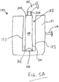
FIG. 5A-B , anexample receptacle compressor 170 is shown. The receptacle compressor comprises aninflatable member 171, such as a bladder. Thebladder 171 defines arecess 172 sized to accommodate thereceptacle 200.Inner walls 173 of the recess are arranged proximate to thewalls receptacle 200. Thereceptacle 200 is placed in fluid communication with thespray applicator 120, for example via a connectingconduit 155 which is in turn fluidly connected to theliquid transmission line 151. Thebladder 171 is connected to an air supply, for example theair pressurising device 130, by viaair inlet 154. Thebladder 171 is resiliently deformable. - In use, air is supplied to the
bladder 171. As shown inFIG. 5B , the increased air pressure inside thebladder 171 causes expansion of thewalls 173 thereof, such that they abut thewalls receptacle 200 and apply a compressive force C thereto. InFIG. 5B , thewalls 173 have expanded sufficiently to begin to compress thereceptacle 200. This causes the egress of liquid from thereceptacle 200, which may in turn cause the liquid to be conveyed to thespray applicator 120. Thewalls 173 continue to expand to further compress thereceptacle 200 until thereservoir 204 is substantially evacuated. - Upon reduction of the air pressure, for example upon opening of a release valve (not shown), the
bladder 171 returns to the initial uninflated configuration shown inFIG. 5A . - In the example of
FIG. 5A-B , thebladder 171 defines arecess 172 withinflatable walls 173, so as to concurrently provide a compressive force to bothwalls receptacle 200. However, in other examples, therecess 172 may have one substantially rigid wall and one inflatable wall. Accordingly, thebladder 171 may apply the compressive force to a single wall of the receptacle. -
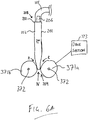
FIG. 6A-6B illustrates another example receptacle compressor 370. The receptacle compressor 370 comprises a pair of rollers 371. The rollers 371 are spaced apart such that a nip N is defined between the rollers. For example, the rollers 371 are arranged so that theirrotational axes 372 are substantially parallel. - The nip N is sized such that progression of the
receptacle 200 through the nip N causes compression of thereceptacle 200. For example, the width of the nip N may be substantially less than the depth of the filledreceptacle 200. By "depth", it is meant the distance between thewalls - In one example, one of the rollers 371 is a driven
roller 371a. Accordingly, the receptacle compressor 370 may comprise adrive section 373 configured to rotate theroller 371a in the direction R to draw thereceptacle 200 through the rollers 371. Thedrive section 373 may comprise a motor (not shown) and suitable gearing or linkages to connect the motor to theroller 371a. In some examples, both rollers 371 are driven. In one example, the rollers 371 comprise a high-friction surface to assist engagement with thereceptacle 200. - In use, the
bottom end 209 of thereceptacle 200 is placed in the nip N. Theroller 371a is driven, causing thereceptacle 200 to be progressively drawn through the rollers from thebottom end 209 to thetop end 208. As thereceptacle 200 is drawn through the rollers 371, the relative narrowness of the nip with respect to the width of thereceptacle 200 causes compression of thereceptacle 200, thereby forcing egress of the liquid from thereservoir 204 viaoutlet 205 alongconduit 155. - In another example, the rollers 371 are configured to translate over the
receptacle 200. For example, thedrive section 373 may be configured to translate the rollers 371 from thebottom end 209 of the receptacle 20 to thetop end 208. In such an example, the rollers 371 may rotate freely rather than being driven. -
FIG. 7A-C show anotherexample receptacle compressor 470. The receptacle compressor comprises aframe 471. Theframe 471 is generally U-shaped in cross-section, and comprise two parallel generallyvertical panels 471a, 471c forming the side walls of theframe 471, connected by a generallyhorizontal panel 471b forming the bottom of the U. - The
receptacle compressor 470 further comprises amovable wall 475 disposed within theframe 471. Themovable wall 475 may be formed of afirst panel 472 and asecond panel 473. One side of thesecond panel 473 is hingedly connected to theframe 471, at a position proximate to the junction of thepanels second panel 473 is in turn hingedly connected to thefirst panel 472. - The
receptacle compressor 470 may further comprise alinkage 474 configured to move thewall 475 towards thewall 471c. For example, thelinkage 474 may comprise a pair of arms. Each arm extends between thewall 471c andwall 475, at respective ends of theframe 471. The arms are rotatably secured to their respective walls at either end. Thelinkage 474 is rotatable in the direction A shown inFIG. 7A-B . Thereceptacle compressor 470 may comprise adrive section 476 to rotate the arms. - In use, a
receptacle 200 is disposed in the gap between thewall 471c and thewall 475. Thelinkage 474 is rotated, causing thepanel 472 to move in a generally arc-shaped path whilst remaining generally vertical. This in turn causes thepanel 473 to rotate from a generally horizontal position towards a vertical position. - The
panels wall 475 apply a compressive force to thereceptacle 200, squeezing thereceptacle 200 so as to cause the egress of liquid from the reservoir. The configuration of thewall 475 is such thatpanel 473 may apply compression to thebottom end 209 of thereceptacle 200 prior to compressing thetop end 208. - In other examples, the
wall 475 may be moved towards thewall 471c by virtue of a piston or other actuator. In further examples, thewalls -
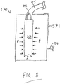
FIG. 8 shows anotherexample receptacle compressor 570. Thereceptacle compressor 570 comprises achamber 571, configured to receive areceptacle 200. Thepressure chamber 571 is connected to an air supply, for example theair pressurising device 130, by viaair inlet 154. - In use, the air pressure is increased in the
pressure chamber 571. The increased air pressure acts on the surface of thereceptacle 200, as generally indicated by the arrows F. This causes compression of thereceptacle 200, thereby forcing the liquid out of thereservoir 204. - Whilst
FIG. 8 shows the application of increased pressure to bothwalls single wall 201 may be compressed. -
FIG. 9 illustrates an example spraying method. Inblock 901, a receptacle is inserted into the housing of a liquid spray system. Inblock 902, the receptacle is compressed to force a liquid therefrom, and convey the liquid to a spray applicator disposed remotely from the housing. Inblock 903, the liquid is propelled the spray applicator using an air pressurising device. The method may comprise further steps, as disclosed herein. - The above-described examples advantageously involve a receptacle comprising liquid that is disposed remotely from the spray applicator (e.g. in a housing in a floor standing or backpack-worn configuration). This may allow for a relatively large reservoir of liquid to be used. This increases the time taken to exhaust the liquid in the reservoir, and thus extending the time between replacement of the receptacle. Accordingly, user convenience is improved. Furthermore, the use of fewer, larger receptacles reduces the ratio of liquid to packaging, reducing packaging costs and transport costs.
- Still further, the disposal of the receptacle remote from the spray applicator ensures that the spray applicator can remain relatively lightweight and easy-to-handle, allowing for an increased degree of freedom of movement of the spray applicator. This advantageously assists the user in accurately dispensing the liquid, for example by accurately spraying a coating composition onto a surface.
- As used herein, unless otherwise expressly specified, all numbers such as those expressing values, ranges, amounts or percentages may be read as if prefaced by the word "about", even if the term does not expressly appear. Also, the recitation of numerical ranges by endpoints includes all integer numbers and, where appropriate, fractions subsumed within that range (e.g. 1 to 5 can include 1, 2, 3, 4 when referring to, for example, a number of elements, and can also include 1.5, 2, 2.75 and 3.80, when referring to, for example, measurements). The recitation of end points also includes the end point values themselves (e.g. from 1.0 to 5.0 includes both 1.0 and 5.0). Any numerical range recited herein is intended to include all sub-ranges subsumed therein.
- Singular encompasses plural and vice versa. For example, although reference is made herein to "a" receptacle compressor, "a" linkage, "a" bladder, and the like, one or more of each of these and any other components can be used.
- The terms "comprising", "comprises" and "comprised of" as used herein are synonymous with "including", "includes" or "containing", "contains", and are inclusive or open-ended and do not exclude additional, non-recited members, elements or method steps. Additionally, although the present invention has been described in terms of "comprising", the liquid spray system detailed herein may also be described as "consisting essentially of" or "consisting of".
- As used herein, the term "and/or," when used in a list of two or more items, means that any one of the listed items can be employed by itself or any combination of two or more of the listed items can be employed. For example, if a list is described as comprising group A, B, and/or C, the list can comprise A alone; B alone; C alone; A and B in combination; A and C in combination, B and C in combination; or A, B, and C in combination.
- Advantageously, the configuration of the liquid spray system allows for the liquid to be propelled from the spray applicator at a relatively low pressure, because the liquid is forced from the receptacle by a receptacle compressor. This may reduce overspray and splashback, allowing the spray applicator to be placed in relatively close proximity to the surface being sprayed. Accordingly, as the distance between spray applicator and surface is minimised, the effects of environmental conditions, such as draughts and wind, are minimised. This may render the liquid spray system advantageously suitable for outdoor applications.
- Attention is directed to all papers and documents which are filed concurrently with or previous to this specification in connection with this application and which are open to public inspection with this specification, and the contents of all such papers and documents are incorporated herein by reference.
- All of the features disclosed in this specification (including any accompanying claims, abstract and drawings), and/or all of the steps of any method or process so disclosed, may be combined in any combination, except combinations where at least some of such features and/or steps are mutually exclusive.
- Each feature disclosed in this specification (including any accompanying claims, abstract and drawings) may be replaced by alternative features serving the same, equivalent or similar purpose, unless expressly stated otherwise. Thus, unless expressly stated otherwise, each feature disclosed is one example only of a generic series of equivalent or similar features.
- The invention is not restricted to the details of the foregoing example(s). The invention extends to any novel one, or any novel combination, of the features disclosed in this specification (including any accompanying claims, abstract and drawings), or to any novel one, or any novel combination, of the steps of any method or process so disclosed.
- Whereas particular embodiments of this invention have been described above for purposes of illustration, it will be evident to those skilled in the art that numerous variations of the details of the present invention may be made without departing from the invention as defined in the appended claims
Claims (19)
- A liquid spray system comprising:a housing comprising:a retaining section configured to receive a receptacle, the receptacle comprising:a flexible body having a reservoir, the reservoir comprising a liquid for spraying; anda liquid outlet in fluid communication with the reservoir;the retaining section comprising a receptacle compressor configured to apply a compressive force to the flexible body to force liquid from the liquid outlet of the receptacle;a spray applicator disposed remotely from the housing and in fluid communication with the liquid outlet of the receptacle; andan air pressurising device in fluid communication with the spray applicator to propel the liquid from the spray applicator.
- The system of claim 1, wherein the receptacle compressor is configured to abut the flexible body to apply the compressive force to the flexible body.
- The system of claim 2, wherein the receptacle compressor comprises a bladder configured to expand to compress the flexible body.
- The system of claim 3, wherein:the bladder is fluidly coupled to the air pressurising device, andthe bladder is configured to expand upon receipt of air from the air pressurising device.
- The system of claim 2, wherein the receptacle compressor comprises:
a pair of rollers arranged in parallel and defining a nip therebetween for receipt of the flexible body, the nip being sized to compress the flexible body. - The system of claim 5, wherein the receptacle compressor comprises a drive section configured to rotate the rollers to draw the flexible body at least partially through the nip.
- The system of claim 5, wherein the receptacle compressor comprises a drive section configured to translate the rollers, thereby rolling the flexible body through the nip.
- The system of claim 2, wherein the receptacle compressor comprises:a first wall and a second wall defining a gap therebetween for receipt of the flexible body, andwherein the second wall is configured to move towards the first wall to narrow the gap, thereby compressing the flexible body.
- The system of claim 8, comprising a linkage connecting the first wall and the second wall, wherein rotation of the linkage causes translation of the second wall towards the first wall.
- The system of any of claims 2-7, wherein the receptacle comprises:a first end having the liquid outlet; anda second end opposite the first end,wherein the receptacle compressor is configured to progressively apply the compressive force starting at the second end and moving towards the first end.
- The system of any preceding claim, wherein the retaining section comprises a recess having a shape complementary to a shape of the flexible body.
- The system of claim 1, wherein the receptacle compressor comprises a pressure chamber configured to receive the flexible body,
wherein the pressure chamber is fluidly coupled to the air pressurising device to increase the air pressure in the chamber, so as to compress the flexible body. - The system of any preceding claim, wherein the spray applicator is a hand-held spray applicator.
- The system of any preceding claim, wherein the housing is configured to rest on a floor or other support surface in use.
- The system of any preceding claim, wherein the housing is configured to be worn on a user's back.
- The system of any preceding claim, wherein the liquid is a coating composition, such as a paint or varnish.
- A kit of parts comprising the liquid spray system of any preceding claim, and a receptacle.
- A spraying method comprising:inserting a receptacle into a housing of a liquid spray system;compressing the receptacle to force a liquid therefrom and convey the liquid to a spray applicator disposed remotely from the housing; andpropelling the liquid from the spray applicator using an air pressurising device.
- Use of a receptacle in the liquid spray system of any of claims 1-16, the receptacle comprising:a flexible body having a reservoir, the reservoir comprising a liquid for spraying; anda liquid outlet in fluid communication with the reservoir.
Priority Applications (6)
| Application Number | Priority Date | Filing Date | Title |
|---|---|---|---|
| EP20182654.2A EP3928876A1 (en) | 2020-06-26 | 2020-06-26 | Liquid spray system and method of spraying |
| AU2021295455A AU2021295455A1 (en) | 2020-06-26 | 2021-06-24 | Liquid spray system and method of spraying |
| EP21735708.6A EP4171836A1 (en) | 2020-06-26 | 2021-06-24 | Liquid spray system and method of spraying |
| US18/002,422 US20230249204A1 (en) | 2020-06-26 | 2021-06-24 | Liquid spray system and method of spraying |
| PCT/EP2021/067424 WO2021260151A1 (en) | 2020-06-26 | 2021-06-24 | Liquid spray system and method of spraying |
| MX2022015700A MX2022015700A (en) | 2020-06-26 | 2021-06-24 | Liquid spray system and method of spraying. |
Applications Claiming Priority (1)
| Application Number | Priority Date | Filing Date | Title |
|---|---|---|---|
| EP20182654.2A EP3928876A1 (en) | 2020-06-26 | 2020-06-26 | Liquid spray system and method of spraying |
Publications (1)
| Publication Number | Publication Date |
|---|---|
| EP3928876A1 true EP3928876A1 (en) | 2021-12-29 |
Family
ID=71266366
Family Applications (2)
| Application Number | Title | Priority Date | Filing Date |
|---|---|---|---|
| EP20182654.2A Withdrawn EP3928876A1 (en) | 2020-06-26 | 2020-06-26 | Liquid spray system and method of spraying |
| EP21735708.6A Pending EP4171836A1 (en) | 2020-06-26 | 2021-06-24 | Liquid spray system and method of spraying |
Family Applications After (1)
| Application Number | Title | Priority Date | Filing Date |
|---|---|---|---|
| EP21735708.6A Pending EP4171836A1 (en) | 2020-06-26 | 2021-06-24 | Liquid spray system and method of spraying |
Country Status (5)
| Country | Link |
|---|---|
| US (1) | US20230249204A1 (en) |
| EP (2) | EP3928876A1 (en) |
| AU (1) | AU2021295455A1 (en) |
| MX (1) | MX2022015700A (en) |
| WO (1) | WO2021260151A1 (en) |
Citations (7)
| Publication number | Priority date | Publication date | Assignee | Title |
|---|---|---|---|---|
| US4136802A (en) * | 1977-09-21 | 1979-01-30 | The Continental Group, Inc. | Spray dispenser with spring biased flexible container |
| WO2011045329A1 (en) | 2009-10-16 | 2011-04-21 | Ppg Europe B.V. | Pouch for paint colourant |
| WO2011048285A1 (en) * | 2009-10-07 | 2011-04-28 | Scorgim | Storage device and method for dispensing a fluid or viscous material |
| US20130062366A1 (en) * | 2011-09-09 | 2013-03-14 | Fountain Master, Llc. | Beverage Maker |
| US20180147586A1 (en) * | 2015-05-22 | 2018-05-31 | Sata Gmbh & Co. Kg | Device for coating surfaces, particularly coloured or painted surfaces |
| EP3485982A1 (en) * | 2017-11-21 | 2019-05-22 | PPG Europe B.V. | Spray system and method of spraying |
| US10370237B2 (en) * | 2012-10-10 | 2019-08-06 | Raymond Wilson Blackburn | Fluid dispenser with isolation membrane |
Family Cites Families (1)
| Publication number | Priority date | Publication date | Assignee | Title |
|---|---|---|---|---|
| US20070194052A1 (en) * | 2004-03-31 | 2007-08-23 | Illinois Tool Works, Inc. | Ergonomic fluid dispenser |
-
2020
- 2020-06-26 EP EP20182654.2A patent/EP3928876A1/en not_active Withdrawn
-
2021
- 2021-06-24 MX MX2022015700A patent/MX2022015700A/en unknown
- 2021-06-24 US US18/002,422 patent/US20230249204A1/en active Pending
- 2021-06-24 AU AU2021295455A patent/AU2021295455A1/en not_active Abandoned
- 2021-06-24 WO PCT/EP2021/067424 patent/WO2021260151A1/en unknown
- 2021-06-24 EP EP21735708.6A patent/EP4171836A1/en active Pending
Patent Citations (7)
| Publication number | Priority date | Publication date | Assignee | Title |
|---|---|---|---|---|
| US4136802A (en) * | 1977-09-21 | 1979-01-30 | The Continental Group, Inc. | Spray dispenser with spring biased flexible container |
| WO2011048285A1 (en) * | 2009-10-07 | 2011-04-28 | Scorgim | Storage device and method for dispensing a fluid or viscous material |
| WO2011045329A1 (en) | 2009-10-16 | 2011-04-21 | Ppg Europe B.V. | Pouch for paint colourant |
| US20130062366A1 (en) * | 2011-09-09 | 2013-03-14 | Fountain Master, Llc. | Beverage Maker |
| US10370237B2 (en) * | 2012-10-10 | 2019-08-06 | Raymond Wilson Blackburn | Fluid dispenser with isolation membrane |
| US20180147586A1 (en) * | 2015-05-22 | 2018-05-31 | Sata Gmbh & Co. Kg | Device for coating surfaces, particularly coloured or painted surfaces |
| EP3485982A1 (en) * | 2017-11-21 | 2019-05-22 | PPG Europe B.V. | Spray system and method of spraying |
Also Published As
| Publication number | Publication date |
|---|---|
| MX2022015700A (en) | 2023-01-24 |
| WO2021260151A1 (en) | 2021-12-30 |
| US20230249204A1 (en) | 2023-08-10 |
| AU2021295455A1 (en) | 2023-02-09 |
| EP4171836A1 (en) | 2023-05-03 |
Similar Documents
| Publication | Publication Date | Title |
|---|---|---|
| US9421560B2 (en) | Method and apparatus to deliver a fluid mixture | |
| CN111674638B (en) | Full-automatic packaging bag opening and sealing processing system | |
| US7980045B2 (en) | Systems and methods for filling a collapsible container | |
| US20050218157A1 (en) | Ergonomic fluid dispenser | |
| CA2136460A1 (en) | Viscous Material Dispenser and Method for Dispensing | |
| US11697549B2 (en) | Flexible container liner wringing device and liner | |
| ZA200806416B (en) | Loading and unloading device for receptacles, such as containers, silos and other filling spaces | |
| US20070235471A1 (en) | Back pack applicator for coatings or sealants | |
| US20050230416A1 (en) | Ergonomic fluid dispenser | |
| US20070194052A1 (en) | Ergonomic fluid dispenser | |
| EP3928876A1 (en) | Liquid spray system and method of spraying | |
| US11634273B2 (en) | Flexible container liner wringing device and liner | |
| GB2283062A (en) | Method and apparatus for use with inflatable stowage pads for transport purposes | |
| CN109353680A (en) | A kind of water paint is taken automatically and save set | |
| CN115569794A (en) | Bottom coating device of aluminum aerosol can and using method thereof | |
| CN111762388B (en) | Full-automatic packaging bag opening and sealing processing technology | |
| CN107298205B (en) | Bag taking and bagging device of full-automatic production line for packaging nested inner bag materials and outer bag materials | |
| US20010016708A1 (en) | Fluid displacement pumps | |
| CA2244019A1 (en) | Viscous material dispenser and method for dispensing | |
| CN110949776B (en) | Paper bag packaging equipment | |
| CN108380414A (en) | A kind of plater easy to use | |
| CN213377492U (en) | Gluing device of gluing machine | |
| CN210247737U (en) | Fruit young fruit bagging device | |
| CN112252682A (en) | Multi-angle pit repairing and wall painting device | |
| CN117775401A (en) | Gel filling equipment |
Legal Events
| Date | Code | Title | Description |
|---|---|---|---|
| PUAI | Public reference made under article 153(3) epc to a published international application that has entered the european phase |
Free format text: ORIGINAL CODE: 0009012 |
|
| STAA | Information on the status of an ep patent application or granted ep patent |
Free format text: STATUS: THE APPLICATION HAS BEEN PUBLISHED |
|
| AK | Designated contracting states |
Kind code of ref document: A1 Designated state(s): AL AT BE BG CH CY CZ DE DK EE ES FI FR GB GR HR HU IE IS IT LI LT LU LV MC MK MT NL NO PL PT RO RS SE SI SK SM TR |
|
| B565 | Issuance of search results under rule 164(2) epc |
Effective date: 20210514 |
|
| STAA | Information on the status of an ep patent application or granted ep patent |
Free format text: STATUS: THE APPLICATION IS DEEMED TO BE WITHDRAWN |
|
| 18D | Application deemed to be withdrawn |
Effective date: 20220630 |