EP3928855A1 - Drive key for rotating equipment accommodating center line misalignment while minimizing hysteresis - Google Patents
Drive key for rotating equipment accommodating center line misalignment while minimizing hysteresis Download PDFInfo
- Publication number
- EP3928855A1 EP3928855A1 EP21173276.3A EP21173276A EP3928855A1 EP 3928855 A1 EP3928855 A1 EP 3928855A1 EP 21173276 A EP21173276 A EP 21173276A EP 3928855 A1 EP3928855 A1 EP 3928855A1
- Authority
- EP
- European Patent Office
- Prior art keywords
- drive key
- stem
- square side
- square
- longitudinal bump
- Prior art date
- Legal status (The legal status is an assumption and is not a legal conclusion. Google has not performed a legal analysis and makes no representation as to the accuracy of the status listed.)
- Pending
Links
- 238000000034 method Methods 0.000 claims description 19
- 239000002594 sorbent Substances 0.000 description 22
- 239000007789 gas Substances 0.000 description 16
- 239000012535 impurity Substances 0.000 description 10
- 230000008569 process Effects 0.000 description 7
- CURLTUGMZLYLDI-UHFFFAOYSA-N Carbon dioxide Chemical compound O=C=O CURLTUGMZLYLDI-UHFFFAOYSA-N 0.000 description 4
- 238000004140 cleaning Methods 0.000 description 4
- 230000006835 compression Effects 0.000 description 4
- 238000007906 compression Methods 0.000 description 4
- 239000011324 bead Substances 0.000 description 3
- 239000012530 fluid Substances 0.000 description 3
- 230000001788 irregular Effects 0.000 description 3
- 238000011282 treatment Methods 0.000 description 3
- 229910002092 carbon dioxide Inorganic materials 0.000 description 2
- 239000001569 carbon dioxide Substances 0.000 description 2
- 238000001311 chemical methods and process Methods 0.000 description 2
- 230000004308 accommodation Effects 0.000 description 1
- 230000002411 adverse Effects 0.000 description 1
- 230000009286 beneficial effect Effects 0.000 description 1
- 230000008859 change Effects 0.000 description 1
- 230000003111 delayed effect Effects 0.000 description 1
- 230000000694 effects Effects 0.000 description 1
- 239000000463 material Substances 0.000 description 1
- 238000005259 measurement Methods 0.000 description 1
- 238000012986 modification Methods 0.000 description 1
- 230000004048 modification Effects 0.000 description 1
- 238000001179 sorption measurement Methods 0.000 description 1
- 239000000126 substance Substances 0.000 description 1
- 230000008719 thickening Effects 0.000 description 1
Images






Classifications
-
- B—PERFORMING OPERATIONS; TRANSPORTING
- B01—PHYSICAL OR CHEMICAL PROCESSES OR APPARATUS IN GENERAL
- B01D—SEPARATION
- B01D53/00—Separation of gases or vapours; Recovering vapours of volatile solvents from gases; Chemical or biological purification of waste gases, e.g. engine exhaust gases, smoke, fumes, flue gases, aerosols
- B01D53/02—Separation of gases or vapours; Recovering vapours of volatile solvents from gases; Chemical or biological purification of waste gases, e.g. engine exhaust gases, smoke, fumes, flue gases, aerosols by adsorption, e.g. preparative gas chromatography
- B01D53/04—Separation of gases or vapours; Recovering vapours of volatile solvents from gases; Chemical or biological purification of waste gases, e.g. engine exhaust gases, smoke, fumes, flue gases, aerosols by adsorption, e.g. preparative gas chromatography with stationary adsorbents
- B01D53/0407—Constructional details of adsorbing systems
-
- F—MECHANICAL ENGINEERING; LIGHTING; HEATING; WEAPONS; BLASTING
- F16—ENGINEERING ELEMENTS AND UNITS; GENERAL MEASURES FOR PRODUCING AND MAINTAINING EFFECTIVE FUNCTIONING OF MACHINES OR INSTALLATIONS; THERMAL INSULATION IN GENERAL
- F16K—VALVES; TAPS; COCKS; ACTUATING-FLOATS; DEVICES FOR VENTING OR AERATING
- F16K11/00—Multiple-way valves, e.g. mixing valves; Pipe fittings incorporating such valves
- F16K11/02—Multiple-way valves, e.g. mixing valves; Pipe fittings incorporating such valves with all movable sealing faces moving as one unit
- F16K11/08—Multiple-way valves, e.g. mixing valves; Pipe fittings incorporating such valves with all movable sealing faces moving as one unit comprising only taps or cocks
- F16K11/087—Multiple-way valves, e.g. mixing valves; Pipe fittings incorporating such valves with all movable sealing faces moving as one unit comprising only taps or cocks with spherical plug
- F16K11/0873—Multiple-way valves, e.g. mixing valves; Pipe fittings incorporating such valves with all movable sealing faces moving as one unit comprising only taps or cocks with spherical plug the plug being only rotatable around one spindle
-
- B—PERFORMING OPERATIONS; TRANSPORTING
- B01—PHYSICAL OR CHEMICAL PROCESSES OR APPARATUS IN GENERAL
- B01D—SEPARATION
- B01D53/00—Separation of gases or vapours; Recovering vapours of volatile solvents from gases; Chemical or biological purification of waste gases, e.g. engine exhaust gases, smoke, fumes, flue gases, aerosols
- B01D53/02—Separation of gases or vapours; Recovering vapours of volatile solvents from gases; Chemical or biological purification of waste gases, e.g. engine exhaust gases, smoke, fumes, flue gases, aerosols by adsorption, e.g. preparative gas chromatography
- B01D53/04—Separation of gases or vapours; Recovering vapours of volatile solvents from gases; Chemical or biological purification of waste gases, e.g. engine exhaust gases, smoke, fumes, flue gases, aerosols by adsorption, e.g. preparative gas chromatography with stationary adsorbents
- B01D53/0407—Constructional details of adsorbing systems
- B01D53/0446—Means for feeding or distributing gases
-
- F—MECHANICAL ENGINEERING; LIGHTING; HEATING; WEAPONS; BLASTING
- F16—ENGINEERING ELEMENTS AND UNITS; GENERAL MEASURES FOR PRODUCING AND MAINTAINING EFFECTIVE FUNCTIONING OF MACHINES OR INSTALLATIONS; THERMAL INSULATION IN GENERAL
- F16K—VALVES; TAPS; COCKS; ACTUATING-FLOATS; DEVICES FOR VENTING OR AERATING
- F16K11/00—Multiple-way valves, e.g. mixing valves; Pipe fittings incorporating such valves
- F16K11/10—Multiple-way valves, e.g. mixing valves; Pipe fittings incorporating such valves with two or more closure members not moving as a unit
- F16K11/14—Multiple-way valves, e.g. mixing valves; Pipe fittings incorporating such valves with two or more closure members not moving as a unit operated by one actuating member, e.g. a handle
- F16K11/16—Multiple-way valves, e.g. mixing valves; Pipe fittings incorporating such valves with two or more closure members not moving as a unit operated by one actuating member, e.g. a handle which only slides, or only turns, or only swings in one plane
- F16K11/163—Multiple-way valves, e.g. mixing valves; Pipe fittings incorporating such valves with two or more closure members not moving as a unit operated by one actuating member, e.g. a handle which only slides, or only turns, or only swings in one plane only turns
- F16K11/166—Multiple-way valves, e.g. mixing valves; Pipe fittings incorporating such valves with two or more closure members not moving as a unit operated by one actuating member, e.g. a handle which only slides, or only turns, or only swings in one plane only turns with the rotating spindles at right angles to the closure members
-
- F—MECHANICAL ENGINEERING; LIGHTING; HEATING; WEAPONS; BLASTING
- F16—ENGINEERING ELEMENTS AND UNITS; GENERAL MEASURES FOR PRODUCING AND MAINTAINING EFFECTIVE FUNCTIONING OF MACHINES OR INSTALLATIONS; THERMAL INSULATION IN GENERAL
- F16K—VALVES; TAPS; COCKS; ACTUATING-FLOATS; DEVICES FOR VENTING OR AERATING
- F16K27/00—Construction of housing; Use of materials therefor
- F16K27/003—Housing formed from a plurality of the same valve elements
-
- F—MECHANICAL ENGINEERING; LIGHTING; HEATING; WEAPONS; BLASTING
- F16—ENGINEERING ELEMENTS AND UNITS; GENERAL MEASURES FOR PRODUCING AND MAINTAINING EFFECTIVE FUNCTIONING OF MACHINES OR INSTALLATIONS; THERMAL INSULATION IN GENERAL
- F16K—VALVES; TAPS; COCKS; ACTUATING-FLOATS; DEVICES FOR VENTING OR AERATING
- F16K5/00—Plug valves; Taps or cocks comprising only cut-off apparatus having at least one of the sealing faces shaped as a more or less complete surface of a solid of revolution, the opening and closing movement being predominantly rotary
- F16K5/04—Plug valves; Taps or cocks comprising only cut-off apparatus having at least one of the sealing faces shaped as a more or less complete surface of a solid of revolution, the opening and closing movement being predominantly rotary with plugs having cylindrical surfaces; Packings therefor
- F16K5/0442—Spindles and actuating means
-
- B—PERFORMING OPERATIONS; TRANSPORTING
- B01—PHYSICAL OR CHEMICAL PROCESSES OR APPARATUS IN GENERAL
- B01D—SEPARATION
- B01D2259/00—Type of treatment
- B01D2259/40—Further details for adsorption processes and devices
- B01D2259/40003—Methods relating to valve switching
- B01D2259/40005—Methods relating to valve switching using rotary valves
-
- F—MECHANICAL ENGINEERING; LIGHTING; HEATING; WEAPONS; BLASTING
- F16—ENGINEERING ELEMENTS AND UNITS; GENERAL MEASURES FOR PRODUCING AND MAINTAINING EFFECTIVE FUNCTIONING OF MACHINES OR INSTALLATIONS; THERMAL INSULATION IN GENERAL
- F16D—COUPLINGS FOR TRANSMITTING ROTATION; CLUTCHES; BRAKES
- F16D3/00—Yielding couplings, i.e. with means permitting movement between the connected parts during the drive
- F16D3/02—Yielding couplings, i.e. with means permitting movement between the connected parts during the drive adapted to specific functions
- F16D3/10—Couplings with means for varying the angular relationship of two coaxial shafts during motion
-
- Y—GENERAL TAGGING OF NEW TECHNOLOGICAL DEVELOPMENTS; GENERAL TAGGING OF CROSS-SECTIONAL TECHNOLOGIES SPANNING OVER SEVERAL SECTIONS OF THE IPC; TECHNICAL SUBJECTS COVERED BY FORMER USPC CROSS-REFERENCE ART COLLECTIONS [XRACs] AND DIGESTS
- Y10—TECHNICAL SUBJECTS COVERED BY FORMER USPC
- Y10T—TECHNICAL SUBJECTS COVERED BY FORMER US CLASSIFICATION
- Y10T137/00—Fluid handling
- Y10T137/598—With repair, tapping, assembly, or disassembly means
- Y10T137/6031—Assembling or disassembling rotary valve
- Y10T137/6035—Rotary ball valve
Definitions
- the subject matter disclosed herein relates generally to the field of rotary valve system for routing gas flow in a twin bed treatment system, and specifically to a drive key for rotating equipment accommodating center line misalignment while minimizing hysteresis.
- Systems provide breathable air through an adsorption process.
- at least two beds which include a sorbent material, such as sorbent beads, are operated in combination.
- a gas stream containing impurities, such as carbon dioxide in air is passed through a first sorbent bed.
- the impurities, such as carbon dioxide are removed by the sorbent beads, and a cleaned air stream is passed downstream to a use.
- the use might be a space suit, a space station, a submarine, or any other habituated environment which does not have ready access to breathable air.
- the gas stream containing the impurities typically returns from this use.
- a second sorbent bed is being desorbed.
- a cleaning or sweep gas is passed through the second bed, and removes impurities.
- the sweep gas and the entrained impurities are passed to a treatment process, or vented into an atmosphere about the environment. While the term "sweep gas" may be utilized in this application, it should be understood that the sweep gas functionality may also be accomplished with the application of a vacuum to remove the impurities.
- valve system is required for these systems to alternately connect the beds in a continuous cycle. Often, separate valve members and valve actuators have been provided for each of the beds. Linear actuators have also been utilized.
- a rotary valve includes a first ball valve including a first stem extending from a first proximal stem end to a first distal stem end outward from the first ball valve.
- the first stem including a first slotted opening extending from the first distal stem end into the first stem.
- the rotary valve includes a second ball valve including a second stem extending from a second proximal stem end to a second distal stem end outward from the second ball valve.
- the second stem including a second slotted opening extending from the second distal stem end into the second stem, wherein the second stem extends towards the first stem.
- the rotary valve includes a drive key located within the first slotted opening and the second slotted opening. The drive key extending from the first slotted opening of the first ball valve to the second slotted opening of the second ball valve to operably connect the first ball valve to the second ball valve.
- the drive key has a non-uniform thickness.
- further embodiments may include that a first thickness proximate a middle of the drive key is less than a second thickness proximate a first outer end of the drive key and a second outer end of the drive key.
- further embodiments may include that the drive key is a square prism.
- drive key includes a first square side surface and a second square side surface opposite the first square side surface.
- the drive key includes: a first rectangular side surface extending from the first square side surface to the second square side surface and a second rectangular side surface extending from the first square side surface to the second square side surface.
- the second rectangular side surface being located at the first outer end of the drive key.
- the drive key also includes a third rectangular side surface located opposite the first rectangular side surface.
- the third rectangular side surface extending from the first square side surface to the second square side surface.
- the drive key also includes fourth rectangular side surface located opposite the second rectangular side surface, the fourth rectangular side surface extending from the first square side surface to the second square side surface.
- the fourth rectangular side surface is located at the second outer end of the drive key.
- further embodiments may include that the drive key includes a first longitudinal bump located on the first square side surface, a second longitudinal bump located on the first square side surface, a third longitudinal bump located on the second square side surface, and a fourth longitudinal bump located on the second square side surface.
- further embodiments may include that the third longitudinal bump is located opposite the first longitudinal bump and the fourth longitudinal bump is located opposite the second longitudinal bump.
- the second thickness of the drive key is measured between the third longitudinal bump and the first longitudinal bump.
- the second thickness of the drive key is measured between the fourth longitudinal bump and the second longitudinal bump.
- further embodiments may include that the first longitudinal bump, the second longitudinal bump, the third longitudinal bump, and the fourth longitudinal bump extend continuously or intermittently between the first rectangular side surface and the third rectangular side surface.
- further embodiments may include that the first distal end and the second distal end are separated by a gap having a gap distance.
- the first thickness spans across a first length of the drive key. The first length being greater than or equal to the gap distance.
- a drive key for use in a rotary valve includes a first square side surface, a second square side surface opposite the first square side surface, a first rectangular side surface extending from the first square side surface to the second square side surface, a second rectangular side surface extending from the first square side surface to the second square side surface, and a third rectangular side surface located opposite the first rectangular side surface.
- the third rectangular side surface extending from the first square side surface to the second square side surface.
- the drive key also including a fourth rectangular side surface located opposite the second rectangular side surface. The fourth rectangular side surface extending from the first square side surface to the second square side surface.
- the drive key has a non-uniform thickness.
- further embodiments may include that the drive key has a first thickness proximate a middle of the drive key is less than a second thickness proximate a first outer end of the drive key and a second outer end of the drive key.
- the second rectangular side surface is located at the first outer end of the drive key and the fourth rectangular side surface is located at the second outer end of the drive key.
- further embodiments may include that the drive key includes: a first longitudinal bump located on the first square side surface, a second longitudinal bump located on the first square side surface, a third longitudinal bump located on the second square side surface, and a fourth longitudinal bump located on the second square side surface.
- further embodiments may include that the third longitudinal bump is located opposite the first longitudinal bump and the fourth longitudinal bump is located opposite the second longitudinal bump.
- the second thickness of the drive key is measured between the third longitudinal bump and the first longitudinal bump.
- the second thickness of the drive key is measured between the fourth longitudinal bump and the second longitudinal bump.
- a method of assembling a rotary valve including: obtaining a first ball valve including a first stem extending from a first proximal stem end to a first distal stem end outward from the first ball valve.
- the first stem including a first slotted opening extending from the first distal stem end into the first stem.
- the method also includes: obtaining a second ball valve including a second stem extending from a second proximal stem end to a second distal stem end outward from the second ball valve.
- the second stem including a second slotted opening extending from the second distal stem end into the second stem.
- the second stem extends towards the first stem.
- the method also includes inserting a drive key into the first slotted opening and the second slotted opening.
- the drive key extending from the first slotted opening of the first ball valve to the second slotted opening of the second ball valve to operably connect the first ball valve to the second ball valve.
- the drive key has a non-uniform thickness.
- further embodiments may include that a first thickness proximate a middle of the drive key is less than a second thickness proximate a first outer end of the drive key and a second outer end of the drive key.
- further embodiments may include that the drive key is a square prism.
- drive key includes a first square side surface and a second square side surface opposite the first square side surface.
- the drive key includes: a first rectangular side surface extending from the first square side surface to the second square side surface and a second rectangular side surface extending from the first square side surface to the second square side surface.
- the second rectangular side surface being located at the first outer end of the drive key.
- the drive key includes a third rectangular side surface located opposite the first rectangular side surface.
- the third rectangular side surface extending from the first square side surface to the second square side surface.
- the drive key includes a fourth rectangular side surface located opposite the second rectangular side surface.
- the fourth rectangular side surface extending from the first square side surface to the second square side surface.
- the fourth rectangular side surface is located at the second outer end of the drive key.
- further embodiments may include that the drive key includes a first longitudinal bump located on the first square side surface, a second longitudinal bump located on the first square side surface, a third longitudinal bump located on the second square side surface, and a fourth longitudinal bump located on the second square side surface.
- further embodiments may include that the third longitudinal bump is located opposite the first longitudinal bump and the fourth longitudinal bump is located opposite the second longitudinal bump.
- the second thickness of the drive key is measured between the third longitudinal bump and the first longitudinal bump.
- the second thickness of the drive key is measured between the fourth longitudinal bump and the second longitudinal bump.
- a rotary valve 22 is shown schematically in FIG. 1 , and controls the flow of gases to a second sorbent bed 124 (i.e., sorbent bed B) and a first sorbent bed 34 (i.e., sorbent bed A).
- the second sorbent bed 124 and the first sorbent bed 34 may contain sorbent beads. It is understood that the rotary valve 22 and component thereof may be applicable to any system 20 and are not limited to the system as illustrated.
- a source 30 of air to be cleaned passes through the rotary valve 22 and to a connection 32 leading to the first sorbent bed 34 in the FIG. 1 position.
- the first sorbent bed 34 remove impurities from the air, and pass a clean air stream to a connection 36 leading back through the rotary valve 22 and to an air flow return 38, which would lead to an environment to utilize the air 39.
- the environment may be a spaceship, a space suit, etc. While the application mentioned above are typical, the twin bed process has been utilized for various chemical treatments, and the rotary valve 22 discussed herein would have application in such systems. Generally, the rotary valve 22 discussed herein would be beneficial in any twin bed chemical process wherein the beds are alternatively put in a "cleaning" and "being cleaned” modes as will be explained below.
- a sweep gas is provided from a source 24 through the rotary valve 22, to a connection 25 leading to the second sorbent bed 124.
- This sweep gas will remove impurities which have been previously deposited in second sorbent bed 124, and drive the impurities along with the sweep gas to a connection 27 leading back through the rotary valve 22 to a sweep gas vent or a vacuum via connection 28.
- This gas is typically either treated by chemical processes, or merely vented from the environment.
- the beds 34 and 124 continue to switch between the "cleaning" and “being cleaned” modes.
- a valve housing 40 includes four side connections 42 (i.e., ports), and two top connections or ports 44.
- the ports 44 are placed on a bottom side of FIG. 2A , and four other side connections 42 face into the plane of FIG. 2A and cannot be seen.
- a rotary valve 50 includes four ball valves 52 having a fluid L-shaped connection between port 54 and port 56.
- a driveshaft 58 drives the rotary valve 50, as will be explained below.
- the rotary valve 50 is located in the valve housing 40 but is illustrated outside of the valve housing 40 in FIG. 2A for explanatory purposes.
- Embodiments disclosed herein relate to the interconnection of four ball valve 52 utilizing drive keys 400 (See FIGS. 6-10 ) and how a uniquely designed drive key with a non-uniform thickness can reduce hysteresis, which is a lag in movement between the actuator motor 62 (See FIG. 2c ) and each of the four ball valves 52 and each of the drive keys 400 (See FIGS. 6-10 ) connecting each of the four ball valves 52.
- FIG. 2B which shows portions of the rotary valve 50 within the valve housing 40
- the ball valve 52 is rotatable within the valve housing 40.
- a spring element 160 biases a valve seat 162 upwardly against the port 54 and port 56 to provide a fluid tight seal.
- other valve seats 162 are being biased against the outer periphery 161 of the ball valve 52 to provide a fluid tight seal.
- FIG. 2C a gear box 60 connected to an actuator motor 62 is illustrated.
- An actuator motor 62 drives the driveshaft 58 (see FIG. 2A ) through the gear box 60 to change the location of the ball valves 52.
- the ports 42 on the side include alternate connections to and from each of the first sorbent bed 34 and the second sorbent bed 124.
- One of the top ports 44 may be sweep air in, while the other may be clean air out.
- FIG. 4 the opposed view is illustrated, and includes the air to be cleaned in passing in one port 44 while the sweep gas out connection is in another port 44.
- FIG. 5 a schematic of the first sorbent bed 34 and the second sorbent bed 124 connected to the process air to be cleaned from the source 30, the "cleaned” process air to be utilized by the air flow return 38, the sweep (or cleaning) gas from source 24, and the sweep gas out connection 28 is illustrated.
- FIGS. 6A , 6B , and 7 a cross-sectional view of the rotary valve 50 is illustrated in FIG. 6A to show the connection between two ball valves 52a, 52b and an exploded view of the rotary valve 50 is illustrated in FIG. 7 .
- the two ball valves 52a, 52b include a first ball valve 52a and a second ball valve 52b.
- the first ball valve 52a includes a stem 252a extending outward from the ball valve 52a and towards the second ball valve 52b.
- the second ball valve 52b includes a stem 252b extending outward from second ball valve 52b and towards the first ball valve 52a.
- the stems 252a, 252b extend towards each other through an opening 300 of a stem housing 350.
- Each of the stems 252a, 252b are supported within the opening by a first seal 310 and a second seal 320.
- the first seal 310 being located at a distal stem end 356 of the first stem 252a, 252b and the second seal 320 being located at a proximal stem end 358 of the first stem 252a, 252b.
- the first proximal stem end 358a is located where the first stem 252a, meets the first ball valve 52a and the first distal stem end 356a is located opposite the first proximal stem end 358a.
- the second proximal stem end 358b is located where the second stem 252b, meets the second ball valve 52b and the second distal stem end 356b is located opposite the second proximal stem end 358b.
- the first stem 252a includes a first slotted opening 260a extending from the first distal stem end 356a into the first stem 252a.
- the second stem 252b includes a second slotted opening 260b extending from the second distal stem end 356b into the second stem 252b.
- a drive key 400 is located within the first slotted opening 260a of the first ball valve 52a and the second slotted opening 260b of the second ball valve 52b.
- the drive key 400 extends from the first slotted opening 260a of the first ball valve 52a to the second slotted opening 260b of the second ball valve 52b to operably connect the first ball valve 52a to the second ball valve 52b.
- Previous designs have utilized a drive key that is primarily flat on all surfaces, square in shape, and having a uniform thickness about equivalent to a height H1 of the slotted openings 260a, 260b.
- the uniform thickness being about equivalent to the height H1 of the slotted opening 260a, 260b may cause rotational hysteresis and irregular compression of the seals 310, 320 if the position of the slotted openings 260a, 260b are slightly off due to tolerances or tolerance stack ups.
- the uniform thickness being about equivalent to the height H1 of the slotted opening may also lead to difficulty rotating one ball valve 52 with the other ball valve 52 if the position of the slotted openings 260 are slightly off due to tolerances or tolerance stack ups.
- the thickness of the drive key 400 must be reduced, increasing the clearance between the drive key 400 and the slotted opening, however this leads to an increase in hysteresis.
- An increase in hysteresis or in other words delayed or non-uniform rotation amongst multiple ball valves 52 that otherwise should be in unison or near unison, can lead to improper registration of the seals at 556 (See FIG. 6B ) with respect to the flow path in the ball valve 52 resulting in leakage.
- the drive key 400 illustrated in FIG. 6A has a non-uniform thickness, which corrects this aforementioned irregular compression and hysteresis.
- the non-uniform thickness allows the drive key 400 to be angled slightly between the first slotted opening 260a of the first ball valve 52a and the second slotted opening 260b of the second ball valve 52b.
- the drive key 400 is thinner in thickness proximate the middle 412 of the drive key 400 and thickens out towards a first outer end 414a and a second outer end 414b of the drive key 400.
- FIG. 8 illustrates the first ball valve 52a and the second ball valve 52b.
- FIG. 8 illustrates a first slotted opening 260a in the first stem 252a of the first ball valve 52a that is slightly offset with a second slotted opening 260b in the second stem 252b of the second ball valve 52b.
- the first slotted opening 260a in the first stem 252a of the first ball valve 52a would align with the second slotted opening 260b in the second stem 252b of the second ball valve 52b.
- the drive key 400 being thinner in thickness proximate the middle 412 of the drive key 400 and thickening out towards the first outer end 414a and the second outer end 414b of the drive key 400 allows the slotted opening 260a in the first stem 252a of the first ball valve 52a to be slightly offset with the second slotted opening 260b in the second stem 252b of the second ball valve 52b without adversely affecting the function of the rotary valve 50.
- the drive key 400 has a first thickness T1 proximate the middle 412 of the drive key 400 and thickens out to a second thickness T2 proximate the first outer end 414a and the second outer end 414b of the drive key 400.
- the second thickness T2 is greater in magnitude than the first thickness T1.
- the second thickness is less than or about equal to the height H1 of the slotted openings 260.
- the drive key 400 may have a first thickness T1 that spans across a first length L1 of the drive key 400.
- the first length L1 may be greater than or equal to a gap distance G1 of a gap 280 between a distal stem end 356 of the first stem 252a of the first ball valve 52a and a distal stem end 356 of the second stem 252b of the second ball valve 52b.
- the drive key 400 may be shaped similar to a square prism with two square side surfaces 422a, 422b and four rectangular side surfaces 424a, 424b, 424c, 424d.
- the two square side surfaces 422a, 422b includes a first square side surface 422a and a second square side surface 422b opposite the first square side surface.
- the first square side surfaces 422a and the second square side surface 422b are square in shape.
- the four rectangular side surface 424a, 424b, 424c, 424d includes a first rectangular side surface 424a, a second rectangular side surface 424b, a third rectangular side surface 424c, and a fourth rectangular side surface 424d.
- the first rectangular side surface 424a extends from the first square side surface 422a to the second square side surface 422b.
- the second rectangular side surface 424b extends from the first square side surface 422a to the second square side surface 422b.
- the third rectangular side surface 424c extends from the first square side surface 422a to the second square side surface 422b.
- the fourth rectangular side surface 424d extends from the first square side surface 422a to the second square side surface 422b.
- the third rectangular side surface 424c is located opposite the first rectangular side surface 424a and the fourth rectangular side surface 424d is located opposite the second rectangular side surface 424b.
- the first rectangular side surface 424a, the second rectangular side surface 424b, the third rectangular side surface 424c, and the fourth rectangular side surface 424d are rectangular in shape.
- the second rectangular side surface 424b is located at the first outer end 414a of the drive key 400.
- the fourth rectangular side surface 424d is located at the second outer end 414b of the drive key 400.
- the first square side surface 422a and the second square side surface 422b include longitudinal bumps 420a, 420b, 420c, 420d.
- the longitudinal bumps 420 420a, 420b, 420c, 420d may extend from the first rectangular side surface 424a to the third rectangular side surface 424c.
- the longitudinal bumps 420a, 420b, 420c, 420d. create the second thickness T2 within the drive key 400.
- the drive key 400 has the second thickness T2 at the longitudinal bumps 420a, 420b, 420c, 420d.
- the longitudinal bumps includes a first longitudinal bump 420a located on the first square side surface 422a, a second longitudinal bump 420b located on the first square side surface 422a, a third longitudinal bump 420c located on the second square side surface 422b, and a fourth longitudinal bump 420d located on the second square side surface 422b.
- the third longitudinal bump 420c is located opposite the first longitudinal bump 420a and the fourth longitudinal bump 420d is located opposite the second longitudinal bump 420b.
- the second thickness T2 of the drive key is measured between the third longitudinal bump 420c and the first longitudinal bump 420a.
- the second thickness T2 of the drive key is measured between the fourth longitudinal bump 420d and the second longitudinal bump 420b.
- the ideal shape of the first longitudinal bump 420a and the third longitudinal bump 420c together would comprise a cylinder equal in diameter to thickness T2.
- the radius for first longitudinal bump 420a and the radius for the third longitudinal bump 420c would be equal and the centerlines of these radii would be the same.
- the longitudinal bumps 420a-420d do not have to be continuous between the first rectangular side surface 424a and the third rectangular side surface 424c. In an embodiment, the longitudinal bumps 420a-420d may extend continuously or intermittently between the first rectangular side surface 424a and the third rectangular side surface 424c.
- FIG. 10 a flow chart of method 1000 of assembling a rotary valve 50 is illustrated, in accordance with an embodiment of the disclosure.
- a first ball valve 52a is obtained.
- the first ball valve 52a comprising a first stem 252a extending from a first proximal stem end 358a to a first distal stem end 356a outward from the first ball valve 52a.
- the first stem 252a comprising a first slotted opening 260a extending from the first distal stem end 356a into the first stem 252a.
- a second ball valve 52b is obtained.
- the second ball valve 52b comprising a second stem 252b extending from a second proximal stem end 358b to a second distal stem end 356b outward from the second ball valve 52b.
- the second stem 252b comprising a second slotted opening 260b extending from the second distal stem end 356b into the second stem 252b.
- the second stem 252b extends towards the first stem 252a.
- a drive key 400 inserted into the first slotted opening 260a and the second slotted opening 260b.
- the drive key 400 extending from the first slotted opening 260a of the first ball valve 52a to the second slotted opening 260b of the second ball valve 52b to operably connect the first ball valve 52a to the second ball valve 52b.
- the drive key 400 has a non-uniform thickness.
Landscapes
- Engineering & Computer Science (AREA)
- General Engineering & Computer Science (AREA)
- Mechanical Engineering (AREA)
- Chemical & Material Sciences (AREA)
- Analytical Chemistry (AREA)
- General Chemical & Material Sciences (AREA)
- Oil, Petroleum & Natural Gas (AREA)
- Chemical Kinetics & Catalysis (AREA)
- Taps Or Cocks (AREA)
- Multiple-Way Valves (AREA)
Abstract
Description
- The subject matter disclosed herein relates generally to the field of rotary valve system for routing gas flow in a twin bed treatment system, and specifically to a drive key for rotating equipment accommodating center line misalignment while minimizing hysteresis.
- Systems provide breathable air through an adsorption process. Typically, at least two beds which include a sorbent material, such as sorbent beads, are operated in combination. A gas stream containing impurities, such as carbon dioxide in air, is passed through a first sorbent bed. The impurities, such as carbon dioxide are removed by the sorbent beads, and a cleaned air stream is passed downstream to a use. The use might be a space suit, a space station, a submarine, or any other habituated environment which does not have ready access to breathable air. The gas stream containing the impurities typically returns from this use.
- At the same time as the first sorbent bed is removing impurities and providing clean air, a second sorbent bed is being desorbed. In a desorbed process a cleaning or sweep gas is passed through the second bed, and removes impurities. The sweep gas and the entrained impurities are passed to a treatment process, or vented into an atmosphere about the environment. While the term "sweep gas" may be utilized in this application, it should be understood that the sweep gas functionality may also be accomplished with the application of a vacuum to remove the impurities.
- A valve system is required for these systems to alternately connect the beds in a continuous cycle. Often, separate valve members and valve actuators have been provided for each of the beds. Linear actuators have also been utilized.
- According to one embodiment, a rotary valve is provided. The rotary valve includes a first ball valve including a first stem extending from a first proximal stem end to a first distal stem end outward from the first ball valve. The first stem including a first slotted opening extending from the first distal stem end into the first stem. The rotary valve includes a second ball valve including a second stem extending from a second proximal stem end to a second distal stem end outward from the second ball valve. The second stem including a second slotted opening extending from the second distal stem end into the second stem, wherein the second stem extends towards the first stem. The rotary valve includes a drive key located within the first slotted opening and the second slotted opening. The drive key extending from the first slotted opening of the first ball valve to the second slotted opening of the second ball valve to operably connect the first ball valve to the second ball valve. The drive key has a non-uniform thickness.
- In addition to one or more of the features described above, or as an alternative, further embodiments may include that a first thickness proximate a middle of the drive key is less than a second thickness proximate a first outer end of the drive key and a second outer end of the drive key.
- In addition to one or more of the features described above, or as an alternative, further embodiments may include that the drive key is a square prism.
- In addition to one or more of the features described above, or as an alternative, further embodiments may include that the drive key includes a first square side surface and a second square side surface opposite the first square side surface.
- In addition to one or more of the features described above, or as an alternative, further embodiments may include that the drive key includes: a first rectangular side surface extending from the first square side surface to the second square side surface and a second rectangular side surface extending from the first square side surface to the second square side surface. The second rectangular side surface being located at the first outer end of the drive key. The drive key also includes a third rectangular side surface located opposite the first rectangular side surface. The third rectangular side surface extending from the first square side surface to the second square side surface. The drive key also includes fourth rectangular side surface located opposite the second rectangular side surface, the fourth rectangular side surface extending from the first square side surface to the second square side surface. The fourth rectangular side surface is located at the second outer end of the drive key.
- In addition to one or more of the features described above, or as an alternative, further embodiments may include that the drive key includes a first longitudinal bump located on the first square side surface, a second longitudinal bump located on the first square side surface, a third longitudinal bump located on the second square side surface, and a fourth longitudinal bump located on the second square side surface.
- In addition to one or more of the features described above, or as an alternative, further embodiments may include that the third longitudinal bump is located opposite the first longitudinal bump and the fourth longitudinal bump is located opposite the second longitudinal bump. The second thickness of the drive key is measured between the third longitudinal bump and the first longitudinal bump. The second thickness of the drive key is measured between the fourth longitudinal bump and the second longitudinal bump.
- In addition to one or more of the features described above, or as an alternative, further embodiments may include that the first longitudinal bump, the second longitudinal bump, the third longitudinal bump, and the fourth longitudinal bump extend continuously or intermittently between the first rectangular side surface and the third rectangular side surface.
- In addition to one or more of the features described above, or as an alternative, further embodiments may include that the first distal end and the second distal end are separated by a gap having a gap distance. The first thickness spans across a first length of the drive key. The first length being greater than or equal to the gap distance.
- According to another embodiment, a drive key for use in a rotary valve is provided. The drive key includes a first square side surface, a second square side surface opposite the first square side surface, a first rectangular side surface extending from the first square side surface to the second square side surface, a second rectangular side surface extending from the first square side surface to the second square side surface, and a third rectangular side surface located opposite the first rectangular side surface. The third rectangular side surface extending from the first square side surface to the second square side surface. The drive key also including a fourth rectangular side surface located opposite the second rectangular side surface. The fourth rectangular side surface extending from the first square side surface to the second square side surface. The drive key has a non-uniform thickness.
- In addition to one or more of the features described above, or as an alternative, further embodiments may include that the drive key has a first thickness proximate a middle of the drive key is less than a second thickness proximate a first outer end of the drive key and a second outer end of the drive key. The second rectangular side surface is located at the first outer end of the drive key and the fourth rectangular side surface is located at the second outer end of the drive key.
- In addition to one or more of the features described above, or as an alternative, further embodiments may include that the drive key includes: a first longitudinal bump located on the first square side surface, a second longitudinal bump located on the first square side surface, a third longitudinal bump located on the second square side surface, and a fourth longitudinal bump located on the second square side surface.
- In addition to one or more of the features described above, or as an alternative, further embodiments may include that the third longitudinal bump is located opposite the first longitudinal bump and the fourth longitudinal bump is located opposite the second longitudinal bump. The second thickness of the drive key is measured between the third longitudinal bump and the first longitudinal bump. The second thickness of the drive key is measured between the fourth longitudinal bump and the second longitudinal bump.
- According to another embodiment, a method of assembling a rotary valve is provided. The method including: obtaining a first ball valve including a first stem extending from a first proximal stem end to a first distal stem end outward from the first ball valve. The first stem including a first slotted opening extending from the first distal stem end into the first stem. The method also includes: obtaining a second ball valve including a second stem extending from a second proximal stem end to a second distal stem end outward from the second ball valve. The second stem including a second slotted opening extending from the second distal stem end into the second stem. The second stem extends towards the first stem. The method also includes inserting a drive key into the first slotted opening and the second slotted opening. The drive key extending from the first slotted opening of the first ball valve to the second slotted opening of the second ball valve to operably connect the first ball valve to the second ball valve. The drive key has a non-uniform thickness.
- In addition to one or more of the features described above, or as an alternative, further embodiments may include that a first thickness proximate a middle of the drive key is less than a second thickness proximate a first outer end of the drive key and a second outer end of the drive key.
- In addition to one or more of the features described above, or as an alternative, further embodiments may include that the drive key is a square prism.
- In addition to one or more of the features described above, or as an alternative, further embodiments may include that the drive key includes a first square side surface and a second square side surface opposite the first square side surface.
- In addition to one or more of the features described above, or as an alternative, further embodiments may include that the drive key includes: a first rectangular side surface extending from the first square side surface to the second square side surface and a second rectangular side surface extending from the first square side surface to the second square side surface. The second rectangular side surface being located at the first outer end of the drive key. The drive key includes a third rectangular side surface located opposite the first rectangular side surface. The third rectangular side surface extending from the first square side surface to the second square side surface. The drive key includes a fourth rectangular side surface located opposite the second rectangular side surface. The fourth rectangular side surface extending from the first square side surface to the second square side surface. The fourth rectangular side surface is located at the second outer end of the drive key.
- In addition to one or more of the features described above, or as an alternative, further embodiments may include that the drive key includes a first longitudinal bump located on the first square side surface, a second longitudinal bump located on the first square side surface, a third longitudinal bump located on the second square side surface, and a fourth longitudinal bump located on the second square side surface.
- In addition to one or more of the features described above, or as an alternative, further embodiments may include that the third longitudinal bump is located opposite the first longitudinal bump and the fourth longitudinal bump is located opposite the second longitudinal bump. The second thickness of the drive key is measured between the third longitudinal bump and the first longitudinal bump. The second thickness of the drive key is measured between the fourth longitudinal bump and the second longitudinal bump.
- The foregoing features and elements may be combined in various combinations without exclusivity, unless expressly indicated otherwise. These features and elements as well as the operation thereof will become more apparent in light of the following description and the accompanying drawings. It should be understood, however, that the following description and drawings are intended to be illustrative and explanatory in nature and non-limiting.
- The following descriptions should not be considered limiting in any way. With reference to the accompanying drawings, like elements are numbered alike:
-
FIG. 1 schematically shows a twin bed system with a rotary valve; -
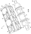
FIG. 2A shows components of the rotary valve; -
FIG. 2B shows a detail of one ball on the rotary valve; -
FIG. 2C shows a drive arrangement for the rotary valve; -
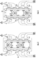
FIG. 3 shows a top view of a rotary valve; -
FIG. 4 shows a bottom view of the rotary valve; -
FIG. 5 shows the schematic of the rotary valve in one application; -
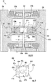
FIG. 6A illustrates a cross-sectional view of the rotary valve, in accordance with an embodiment of the present disclosure; -
FIG. 6B illustrates a cross-sectional view of the rotary valve with improper seal compression; -
FIG. 7 illustrates an exploded view of the rotary valve, in accordance with an embodiment of the present disclosure; -
FIG. 8 illustrates an enlarged cross-sectional view of the rotary valve, in accordance with an embodiment of the present disclosure; -
FIG. 9 illustrates an isometric view of a drive key for the rotary valve, in accordance with an embodiment of the present disclosure; and -
FIG. 10 illustrates a flow chart of a method of assembling the rotary valve, in accordance with an embodiment of the present disclosure. - A detailed description of one or more embodiments of the disclosed apparatus and method are presented herein by way of exemplification and not limitation with reference to the Figures.
- Referring now to
FIG. 1 , asystem 20 for providing a clean air flow is illustrated. Arotary valve 22 is shown schematically inFIG. 1 , and controls the flow of gases to a second sorbent bed 124 (i.e., sorbent bed B) and a first sorbent bed 34 (i.e., sorbent bed A). As mentioned, thesecond sorbent bed 124 and thefirst sorbent bed 34 may contain sorbent beads. It is understood that therotary valve 22 and component thereof may be applicable to anysystem 20 and are not limited to the system as illustrated. - A
source 30 of air to be cleaned passes through therotary valve 22 and to aconnection 32 leading to thefirst sorbent bed 34 in theFIG. 1 position. Thefirst sorbent bed 34 remove impurities from the air, and pass a clean air stream to aconnection 36 leading back through therotary valve 22 and to anair flow return 38, which would lead to an environment to utilize theair 39. As mentioned above, the environment may be a spaceship, a space suit, etc. While the application mentioned above are typical, the twin bed process has been utilized for various chemical treatments, and therotary valve 22 discussed herein would have application in such systems. Generally, therotary valve 22 discussed herein would be beneficial in any twin bed chemical process wherein the beds are alternatively put in a "cleaning" and "being cleaned" modes as will be explained below. - At the same time the air to be cleaned is passing through the
first sorbent bed 34, a sweep gas is provided from asource 24 through therotary valve 22, to aconnection 25 leading to thesecond sorbent bed 124. This sweep gas will remove impurities which have been previously deposited insecond sorbent bed 124, and drive the impurities along with the sweep gas to aconnection 27 leading back through therotary valve 22 to a sweep gas vent or a vacuum viaconnection 28. This gas is typically either treated by chemical processes, or merely vented from the environment. - As is well known, the
beds - Referring now to
FIG. 2A , details of therotary valve 22 are illustrated. As shown, avalve housing 40 includes four side connections 42 (i.e., ports), and two top connections orports 44. Theports 44 are placed on a bottom side ofFIG. 2A , and fourother side connections 42 face into the plane ofFIG. 2A and cannot be seen. - As shown, a
rotary valve 50 includes fourball valves 52 having a fluid L-shaped connection betweenport 54 andport 56. Adriveshaft 58 drives therotary valve 50, as will be explained below. - The
rotary valve 50 is located in thevalve housing 40 but is illustrated outside of thevalve housing 40 inFIG. 2A for explanatory purposes. - Embodiments disclosed herein relate to the interconnection of four
ball valve 52 utilizing drive keys 400 (SeeFIGS. 6-10 ) and how a uniquely designed drive key with a non-uniform thickness can reduce hysteresis, which is a lag in movement between the actuator motor 62 (SeeFIG. 2c ) and each of the fourball valves 52 and each of the drive keys 400 (SeeFIGS. 6-10 ) connecting each of the fourball valves 52. - Referring now to
FIG. 2B , which shows portions of therotary valve 50 within thevalve housing 40, theball valve 52 is rotatable within thevalve housing 40. Aspring element 160 biases avalve seat 162 upwardly against theport 54 andport 56 to provide a fluid tight seal. As can also be appreciated fromFIG. 2B ,other valve seats 162 are being biased against theouter periphery 161 of theball valve 52 to provide a fluid tight seal. - Referring now to
FIG. 2C , agear box 60 connected to anactuator motor 62 is illustrated. Anactuator motor 62 drives the driveshaft 58 (seeFIG. 2A ) through thegear box 60 to change the location of theball valves 52. - Referring now to
FIG. 3 , theports 42 on the side include alternate connections to and from each of thefirst sorbent bed 34 and thesecond sorbent bed 124. One of thetop ports 44 may be sweep air in, while the other may be clean air out. - Referring now to
FIG. 4 , the opposed view is illustrated, and includes the air to be cleaned in passing in oneport 44 while the sweep gas out connection is in anotherport 44. - Referring now to
FIG. 5 , a schematic of thefirst sorbent bed 34 and thesecond sorbent bed 124 connected to the process air to be cleaned from thesource 30, the "cleaned" process air to be utilized by theair flow return 38, the sweep (or cleaning) gas fromsource 24, and the sweep gas outconnection 28 is illustrated. - Referring now to
FIGS. 6A ,6B , and7 , a cross-sectional view of therotary valve 50 is illustrated inFIG. 6A to show the connection between twoball valves rotary valve 50 is illustrated inFIG. 7 . The twoball valves first ball valve 52a and asecond ball valve 52b. Thefirst ball valve 52a includes astem 252a extending outward from theball valve 52a and towards thesecond ball valve 52b. Thesecond ball valve 52b includes astem 252b extending outward fromsecond ball valve 52b and towards thefirst ball valve 52a. - The stems 252a, 252b extend towards each other through an
opening 300 of astem housing 350. Each of thestems first seal 310 and asecond seal 320. Thefirst seal 310 being located at a distal stem end 356 of thefirst stem second seal 320 being located at a proximal stem end 358 of thefirst stem - The first
proximal stem end 358a is located where thefirst stem 252a, meets thefirst ball valve 52a and the firstdistal stem end 356a is located opposite the firstproximal stem end 358a. The secondproximal stem end 358b is located where thesecond stem 252b, meets thesecond ball valve 52b and the seconddistal stem end 356b is located opposite the secondproximal stem end 358b. - The
first stem 252a includes a first slottedopening 260a extending from the firstdistal stem end 356a into thefirst stem 252a. Thesecond stem 252b includes a second slotted opening 260b extending from the seconddistal stem end 356b into thesecond stem 252b. - A
drive key 400 is located within the first slotted opening 260a of thefirst ball valve 52a and the second slotted opening 260b of thesecond ball valve 52b. Thedrive key 400 extends from the first slotted opening 260a of thefirst ball valve 52a to the second slotted opening 260b of thesecond ball valve 52b to operably connect thefirst ball valve 52a to thesecond ball valve 52b. Thus, when either of thefirst ball valve 52a or thesecond ball valve 52b rotates bothball valves - Previous designs have utilized a drive key that is primarily flat on all surfaces, square in shape, and having a uniform thickness about equivalent to a height H1 of the slotted
openings opening seals openings ball valve 52 with theother ball valve 52 if the position of the slotted openings 260 are slightly off due to tolerances or tolerance stack ups. To avoid this situation and accommodate tolerances, the thickness of thedrive key 400 must be reduced, increasing the clearance between thedrive key 400 and the slotted opening, however this leads to an increase in hysteresis. An increase in hysteresis, or in other words delayed or non-uniform rotation amongstmultiple ball valves 52 that otherwise should be in unison or near unison, can lead to improper registration of the seals at 556 (SeeFIG. 6B ) with respect to the flow path in theball valve 52 resulting in leakage. - The
drive key 400 illustrated inFIG. 6A , according to one or more embodiments, has a non-uniform thickness, which corrects this aforementioned irregular compression and hysteresis. The non-uniform thickness allows thedrive key 400 to be angled slightly between the first slotted opening 260a of thefirst ball valve 52a and the second slotted opening 260b of thesecond ball valve 52b. Thedrive key 400 is thinner in thickness proximate the middle 412 of thedrive key 400 and thickens out towards a firstouter end 414a and a secondouter end 414b of thedrive key 400. - Referring now to
FIGS. 8 and 9 , an enlarged cross-sectional view of therotary valve 50 is illustrated inFIG. 8 to show the connection between twoball valves 52 and an isometric view of thedrive key 400 is illustrated inFIG. 9. FIG. 8 illustrates thefirst ball valve 52a and thesecond ball valve 52b.FIG. 8 illustrates a first slottedopening 260a in thefirst stem 252a of thefirst ball valve 52a that is slightly offset with a second slotted opening 260b in thesecond stem 252b of thesecond ball valve 52b. Ideally the first slottedopening 260a in thefirst stem 252a of thefirst ball valve 52a would align with the second slotted opening 260b in thesecond stem 252b of thesecond ball valve 52b. Some tolerances or tolerance stack ups may cause the first slottedopening 260a in thefirst stem 252a of thefirst ball valve 52a to be slightly offset with the second slotted opening 260b in thesecond stem 252b of thesecond ball valve 52b. - The
drive key 400 being thinner in thickness proximate the middle 412 of thedrive key 400 and thickening out towards the firstouter end 414a and the secondouter end 414b of thedrive key 400 allows the slottedopening 260a in thefirst stem 252a of thefirst ball valve 52a to be slightly offset with the second slotted opening 260b in thesecond stem 252b of thesecond ball valve 52b without adversely affecting the function of therotary valve 50. - The
drive key 400 has a first thickness T1 proximate the middle 412 of thedrive key 400 and thickens out to a second thickness T2 proximate the firstouter end 414a and the secondouter end 414b of thedrive key 400. The second thickness T2 is greater in magnitude than the first thickness T1. The second thickness is less than or about equal to the height H1 of the slotted openings 260. - The
drive key 400 may have a first thickness T1 that spans across a first length L1 of thedrive key 400. The first length L1 may be greater than or equal to a gap distance G1 of agap 280 between a distal stem end 356 of thefirst stem 252a of thefirst ball valve 52a and a distal stem end 356 of thesecond stem 252b of thesecond ball valve 52b. - As illustrated in
FIG. 9 , thedrive key 400 may be shaped similar to a square prism with twosquare side surfaces rectangular side surfaces square side surfaces square side surface 422a and a secondsquare side surface 422b opposite the first square side surface. The firstsquare side surfaces 422a and the secondsquare side surface 422b are square in shape. The fourrectangular side surface rectangular side surface 424a, a secondrectangular side surface 424b, a third rectangular side surface 424c, and a fourthrectangular side surface 424d. The firstrectangular side surface 424a extends from the firstsquare side surface 422a to the secondsquare side surface 422b. The secondrectangular side surface 424b extends from the firstsquare side surface 422a to the secondsquare side surface 422b. The third rectangular side surface 424c extends from the firstsquare side surface 422a to the secondsquare side surface 422b. The fourthrectangular side surface 424d extends from the firstsquare side surface 422a to the secondsquare side surface 422b. - The third rectangular side surface 424c is located opposite the first
rectangular side surface 424a and the fourthrectangular side surface 424d is located opposite the secondrectangular side surface 424b. The firstrectangular side surface 424a, the secondrectangular side surface 424b, the third rectangular side surface 424c, and the fourthrectangular side surface 424d are rectangular in shape. The secondrectangular side surface 424b is located at the firstouter end 414a of thedrive key 400. The fourthrectangular side surface 424d is located at the secondouter end 414b of thedrive key 400. - The first
square side surface 422a and the secondsquare side surface 422b includelongitudinal bumps rectangular side surface 424a to the third rectangular side surface 424c. Thelongitudinal bumps drive key 400. In other words, thedrive key 400 has the second thickness T2 at thelongitudinal bumps - The longitudinal bumps includes a first
longitudinal bump 420a located on the firstsquare side surface 422a, a secondlongitudinal bump 420b located on the firstsquare side surface 422a, a thirdlongitudinal bump 420c located on the secondsquare side surface 422b, and a fourthlongitudinal bump 420d located on the secondsquare side surface 422b. - The third
longitudinal bump 420c is located opposite the firstlongitudinal bump 420a and the fourthlongitudinal bump 420d is located opposite the secondlongitudinal bump 420b. The second thickness T2 of the drive key is measured between the thirdlongitudinal bump 420c and the firstlongitudinal bump 420a. The second thickness T2 of the drive key is measured between the fourthlongitudinal bump 420d and the secondlongitudinal bump 420b. For the least amount of hysteresis and maximum amount of mismatch accommodation between slots, the ideal shape of the firstlongitudinal bump 420a and the thirdlongitudinal bump 420c together would comprise a cylinder equal in diameter to thickness T2. In other words, the radius for firstlongitudinal bump 420a and the radius for the thirdlongitudinal bump 420c would be equal and the centerlines of these radii would be the same. However, depending on several variables, it is not required that this be true and the shape of thelongitudinal bumps 420a-420d can deviate from the above ideal condition. Additionally, thelongitudinal bumps 420a-420d do not have to be continuous between the firstrectangular side surface 424a and the third rectangular side surface 424c. In an embodiment, thelongitudinal bumps 420a-420d may extend continuously or intermittently between the firstrectangular side surface 424a and the third rectangular side surface 424c. - Referring now to
FIG. 10 , a flow chart ofmethod 1000 of assembling arotary valve 50 is illustrated, in accordance with an embodiment of the disclosure. - At
block 1004, afirst ball valve 52a is obtained. Thefirst ball valve 52a comprising afirst stem 252a extending from a firstproximal stem end 358a to a firstdistal stem end 356a outward from thefirst ball valve 52a. Thefirst stem 252a comprising a first slottedopening 260a extending from the firstdistal stem end 356a into thefirst stem 252a. - At
block 1006, asecond ball valve 52b is obtained. Thesecond ball valve 52b comprising asecond stem 252b extending from a secondproximal stem end 358b to a seconddistal stem end 356b outward from thesecond ball valve 52b. Thesecond stem 252b comprising a second slotted opening 260b extending from the seconddistal stem end 356b into thesecond stem 252b. Thesecond stem 252b extends towards thefirst stem 252a. - At
block 1008, adrive key 400 inserted into the first slottedopening 260a and the second slotted opening 260b. Thedrive key 400 extending from the first slotted opening 260a of thefirst ball valve 52a to the second slotted opening 260b of thesecond ball valve 52b to operably connect thefirst ball valve 52a to thesecond ball valve 52b. Thedrive key 400 has a non-uniform thickness. - While the above description has described the flow process of
FIG. 10 in a particular order, it should be appreciated that unless otherwise specifically required in the attached claims that the ordering of the steps may be varied. - Technical effects and benefits of the features described herein include utilizing a drive key with a non-uniform thickness in a rotary valve to reduce hysteresis, prevent jamming, and irregular compression of seals.
- A detailed description of one or more embodiments of the disclosed apparatus and method are presented herein by way of exemplification and not limitation with reference to the Figures.
- The term "about" is intended to include the degree of error associated with measurement of the particular quantity based upon the equipment available at the time of filing the application.
- The terminology used herein is for the purpose of describing particular embodiments only and is not intended to be limiting of the present disclosure. As used herein, the singular forms "a", "an" and "the" are intended to include the plural forms as well, unless the context clearly indicates otherwise. It will be further understood that the terms "comprises" and/or "comprising," when used in this specification, specify the presence of stated features, integers, steps, operations, elements, and/or components, but do not preclude the presence or addition of one or more other features, integers, steps, operations, element components, and/or groups thereof.
- While the present disclosure has been described with reference to an exemplary embodiment or embodiments, it will be understood by those skilled in the art that various changes may be made without departing from the scope of the present disclosure. In addition, many modifications may be made to adapt a particular situation or material to the teachings of the present disclosure without departing from the essential scope thereof. Therefore, it is intended that the present disclosure not be limited to the particular embodiment disclosed as the best mode contemplated for carrying out this present disclosure, but that the present disclosure will include all embodiments falling within the scope of the claims.
Claims (15)
- A rotary valve, comprising:a first ball valve (52a) comprising a first stem (252a) extending from a first proximal stem end (358a) to a first distal stem end (356a) outward from the first ball valve, the first stem comprising a first slotted opening (260a) extending from the first distal stem end into the first stem;a second ball valve (52b) comprising a second stem (252b) extending from a second proximal stem end (358b) to a second distal stem end (356b) outward from the second ball valve, the second stem comprising a second slotted opening (260b) extending from the second distal stem end into the second stem, wherein the second stem extends towards the first stem; anda drive key (400) located within the first slotted opening and the second slotted opening, the drive key extending from the first slotted opening of the first ball valve to the second slotted opening of the second ball valve to operably connect the first ball valve to the second ball valve,wherein the drive key has a non-uniform thickness.
- The rotary valve of claim 1, wherein a first thickness proximate a middle of the drive key is less than a second thickness proximate a first outer end (414a) of the drive key and a second outer end (414b) of the drive key.
- The rotary valve of claim 2, wherein the drive key (400) is a square prism.
- The rotary valve of claim 2, wherein the drive key (400) comprises a first square side surface (422a) and a second square side surface (422b) opposite the first square side surface.
- The rotary valve of claim 4, wherein the drive key comprises:a first rectangular side surface (424a) extending from the first square side surface to the second square side surface;a second rectangular side surface (424b) extending from the first square side surface to the second square side surface, the second rectangular side surface being located at the first outer end of the drive key;a third rectangular side surface (424c) located opposite the first rectangular side surface, the third rectangular side surface extending from the first square side surface to the second square side surface; anda fourth rectangular side surface (424d) located opposite the second rectangular side surface, the fourth rectangular side surface extending from the first square side surface to the second square side surface, wherein the fourth rectangular side surface is located at the second outer end of the drive key.
- The rotary valve of claim 5, wherein the drive key (400) comprises:a first longitudinal bump (420a) located on the first square side surface;a second longitudinal bump (420b) located on the first square side surface;a third longitudinal bump (420c) located on the second square side surface; anda fourth longitudinal bump (420d) located on the second square side surface.
- The rotary valve of claim 6, wherein the third longitudinal bump (420c) is located opposite the first longitudinal bump and the fourth longitudinal bump (420d) is located opposite the second longitudinal bump, wherein the second thickness of the drive key is measured between the third longitudinal bump (420c) and the first longitudinal bump (420a), and wherein the second thickness of the drive key is measured between the fourth longitudinal bump (420d) and the second longitudinal bump (420b); and/or
wherein the first longitudinal bump (420a), the second longitudinal bump (420b), the third longitudinal bump (420c), and the fourth longitudinal bump (420d) extend continuously or intermittently between the first rectangular side surface and the third rectangular side surface. - The rotary valve of any preceding claim, wherein the first distal end and the second distal end are separated by a gap having a gap distance, and wherein the first thickness spans across a first length of the drive key, the first length being greater than or equal to the gap distance.
- A drive key (400) for use in a rotary valve, the drive key comprising:a first square side surface (422a);a second square side surface (422b) opposite the first square side surface;a first rectangular side surface (424a) extending from the first square side surface to the second square side surface;a second rectangular side surface (424b) extending from the first square side surface to the second square side surface;a third rectangular side surface (424c) located opposite the first rectangular side surface, the third rectangular side surface extending from the first square side surface to the second square side surface; anda fourth rectangular side surface (424d) located opposite the second rectangular side surface, the fourth rectangular side surface extending from the first square side surface to the second square side surface,wherein the drive key (400) has a non-uniform thickness.
- The drive key of claim 9, wherein the drive key (400) has a first thickness proximate a middle of the drive key is less than a second thickness proximate a first outer end of the drive key and a second outer end of the drive key, and
wherein the second rectangular side surface (424b) is located at the first outer end of the drive key and the fourth rectangular side surface (424d) is located at the second outer end of the drive key. - The drive key of claim 10, wherein the drive key (400) comprises:a first longitudinal bump (420a) located on the first square side surface;a second longitudinal bump (420b) located on the first square side surface;a third longitudinal bump (420c) located on the second square side surface; anda fourth longitudinal bump (420d) located on the second square side surface, and preferably:
wherein the third longitudinal bump (420c) is located opposite the first longitudinal bump (420a) and the fourth longitudinal bump (420d) is located opposite the second longitudinal bump (420b), wherein the second thickness of the drive key is measured between the third longitudinal bump and the first longitudinal bump, and wherein the second thickness of the drive key is measured between the fourth longitudinal bump and the second longitudinal bump. - A method of assembling a rotary valve, the comprising:obtaining a first ball valve comprising a first stem extending from a first proximal stem end to a first distal stem end outward from the first ball valve, the first stem comprising a first slotted opening extending from the first distal stem end into the first stem;obtaining a second ball valve comprising a second stem extending from a second proximal stem end to a second distal stem end outward from the second ball valve, the second stem comprising a second slotted opening extending from the second distal stem end into the second stem, wherein the second stem extends towards the first stem; andinserting a drive key into the first slotted opening and the second slotted opening, the drive key extending from the first slotted opening of the first ball valve to the second slotted opening of the second ball valve to operably connect the first ball valve to the second ball valve,wherein the drive key has a non-uniform thickness.
- The method of claim 12, wherein a first thickness proximate a middle of the drive key is less than a second thickness proximate a first outer end of the drive key and a second outer end of the drive key.
- The method of claim 13, wherein the drive key is a square prism.
- The method of claim 13, wherein the drive key comprises a first square side surface and a second square side surface opposite the first square side surface, and preferably wherein the drive key comprises:a first rectangular side surface extending from the first square side surface to the second square side surface;a second rectangular side surface extending from the first square side surface to the second square side surface, the second rectangular side surface being located at the first outer end of the drive key;a third rectangular side surface located opposite the first rectangular side surface, the third rectangular side surface extending from the first square side surface to the second square side surface; anda fourth rectangular side surface located opposite the second rectangular side surface, the fourth rectangular side surface extending from the first square side surface to the second square side surface, wherein the fourth rectangular side surface is located at the second outer end of the drive key, and more preferably:
wherein the drive key comprises:a first longitudinal bump located on the first square side surface;a second longitudinal bump located on the first square side surface;a third longitudinal bump located on the second square side surface; anda fourth longitudinal bump located on the second square side surface, and more preferably:
wherein the third longitudinal bump is located opposite the first longitudinal bump and the fourth longitudinal bump is located opposite the second longitudinal bump, wherein the second thickness of the drive key is measured between the third longitudinal bump and the first longitudinal bump, and wherein the second thickness of the drive key is measured between the fourth longitudinal bump and the second longitudinal bump.
Applications Claiming Priority (1)
| Application Number | Priority Date | Filing Date | Title |
|---|---|---|---|
| US16/910,696 US11391383B2 (en) | 2020-06-24 | 2020-06-24 | Drive key for rotating equipment accommodating center line misalignment while minimizing hysteresis |
Publications (1)
| Publication Number | Publication Date |
|---|---|
| EP3928855A1 true EP3928855A1 (en) | 2021-12-29 |
Family
ID=75904820
Family Applications (1)
| Application Number | Title | Priority Date | Filing Date |
|---|---|---|---|
| EP21173276.3A Pending EP3928855A1 (en) | 2020-06-24 | 2021-05-11 | Drive key for rotating equipment accommodating center line misalignment while minimizing hysteresis |
Country Status (2)
| Country | Link |
|---|---|
| US (1) | US11391383B2 (en) |
| EP (1) | EP3928855A1 (en) |
Families Citing this family (3)
| Publication number | Priority date | Publication date | Assignee | Title |
|---|---|---|---|---|
| CN116917648A (en) * | 2020-11-19 | 2023-10-20 | 卡莱流体技术有限责任公司 | valves and systems |
| EP4635600A1 (en) * | 2024-03-01 | 2025-10-22 | Sagentia Ltd | Atmospheric co2 removal system |
| CN118088733B (en) * | 2024-04-17 | 2024-07-23 | 新乡市德胜威过滤净化设备有限公司 | Modular series ball valve |
Citations (4)
| Publication number | Priority date | Publication date | Assignee | Title |
|---|---|---|---|---|
| US4887567A (en) * | 1985-04-10 | 1989-12-19 | Honda Giken Kogyo Kabushiki Kaisha | Connecting arrangement in valve operating system for internal combustion engine |
| US5267903A (en) * | 1990-10-03 | 1993-12-07 | Kay Seven Co., Ltd. | Shaft coupling |
| US5443722A (en) * | 1994-06-01 | 1995-08-22 | Mueller Steam Specialty | Duplex strainer |
| US20180080664A1 (en) * | 2015-04-09 | 2018-03-22 | Giacomin S.P.A. | Multiway valve with bypass circuit |
Family Cites Families (21)
| Publication number | Priority date | Publication date | Assignee | Title |
|---|---|---|---|---|
| US3324958A (en) * | 1964-07-20 | 1967-06-13 | Roy A Clark | Soil-sampling apparatus with core dislodging means |
| US3450157A (en) * | 1967-07-31 | 1969-06-17 | John E Hewson | Valve manifold |
| US3528448A (en) * | 1967-10-04 | 1970-09-15 | Lunkenheimer Co | Slurry valve |
| CA931045A (en) * | 1970-05-29 | 1973-07-31 | R. Deane William | Rotary valve |
| US3819149A (en) * | 1973-05-24 | 1974-06-25 | A Kinder | Ball valve |
| US3900401A (en) * | 1974-11-04 | 1975-08-19 | Us Navy | Dual filter for lubricating oil |
| US4175580A (en) * | 1977-11-21 | 1979-11-27 | Kalbfleisch Adolphe W | Bottom entry positive acting ball valve |
| IT1138544B (en) | 1981-09-02 | 1986-09-17 | Nuovo Pignone Spa | PERFECTED KEY FOR BALL VALVES OPERATION |
| US4475712A (en) * | 1982-01-07 | 1984-10-09 | Xomox Corporation | Fluid valve and method of making same |
| US4593570A (en) * | 1985-04-01 | 1986-06-10 | Niskin Shale J | Water sampler device with key |
| US5127628A (en) | 1991-11-04 | 1992-07-07 | Fike Corporation | Means for rotating ball valves between open and closed positions |
| US6197195B1 (en) * | 1999-03-29 | 2001-03-06 | H-Tech, Inc. | Fluid handling apparatus and flow control assembly therefor |
| US20020145126A1 (en) * | 2001-04-09 | 2002-10-10 | Bing-Tson Lian | Ball valve |
| US6886508B1 (en) * | 2001-08-15 | 2005-05-03 | William D. Luffy | Dual shut-off valve for two-cycle engines |
| US7306010B2 (en) * | 2005-02-15 | 2007-12-11 | Nibco Inc. | Ball valve with snap-in stem |
| US7506665B2 (en) * | 2005-02-15 | 2009-03-24 | Nibco Inc. | Ball valve with interlocking stem |
| US7854794B2 (en) * | 2008-07-28 | 2010-12-21 | Barone Michael R | Rotary valve element for twin bed alternative treatment systems |
| US8356627B2 (en) * | 2009-07-23 | 2013-01-22 | Tokyo Keiso Co., Ltd. | Three-valves manifold for differential pressure type flow meter |
| US10215290B2 (en) * | 2016-04-29 | 2019-02-26 | Cameron International Corporation | Plug with attachable upper trunnion |
| US10641398B2 (en) * | 2016-05-13 | 2020-05-05 | Red-White Valve Corp. | Ball valve with integrated fitting |
| US10465803B2 (en) * | 2016-10-05 | 2019-11-05 | Johnson Controls Technology Company | Multipurpose valve assembly tool |
-
2020
- 2020-06-24 US US16/910,696 patent/US11391383B2/en active Active
-
2021
- 2021-05-11 EP EP21173276.3A patent/EP3928855A1/en active Pending
Patent Citations (4)
| Publication number | Priority date | Publication date | Assignee | Title |
|---|---|---|---|---|
| US4887567A (en) * | 1985-04-10 | 1989-12-19 | Honda Giken Kogyo Kabushiki Kaisha | Connecting arrangement in valve operating system for internal combustion engine |
| US5267903A (en) * | 1990-10-03 | 1993-12-07 | Kay Seven Co., Ltd. | Shaft coupling |
| US5443722A (en) * | 1994-06-01 | 1995-08-22 | Mueller Steam Specialty | Duplex strainer |
| US20180080664A1 (en) * | 2015-04-09 | 2018-03-22 | Giacomin S.P.A. | Multiway valve with bypass circuit |
Also Published As
| Publication number | Publication date |
|---|---|
| US20210404566A1 (en) | 2021-12-30 |
| US11391383B2 (en) | 2022-07-19 |
Similar Documents
| Publication | Publication Date | Title |
|---|---|---|
| US11391383B2 (en) | Drive key for rotating equipment accommodating center line misalignment while minimizing hysteresis | |
| US7854794B2 (en) | Rotary valve element for twin bed alternative treatment systems | |
| CA2448859C (en) | Rotary sequencing valve with flexible port plate | |
| US7500490B2 (en) | Rotary valve with internal leak control system | |
| CN101446361B (en) | rotary valve | |
| KR100939055B1 (en) | Pressure fluctuation adsorber with rotary indexing multiport valve | |
| US20060283325A1 (en) | Oxygen concentrating apparatus and rotary valve | |
| EP1509312B1 (en) | Method and apparatus for pressure swing adsorption | |
| US20010047824A1 (en) | Rotary valve assembly for pressure swing absorption system | |
| WO2010039353A1 (en) | Indexed rotatable multiport valve for vpsa | |
| CN105899795A (en) | Insertion structure, carbon tank and carbon tank discharge solenoid valve | |
| US20040164264A1 (en) | Seal ring for pendulum valve assembly | |
| JP3481462B2 (en) | Oxygen concentrator | |
| WO2006112546A1 (en) | Oxygen enriching device | |
| KR100594493B1 (en) | Distributing Valve to Prevent Backflow of Waste Gas Treatment System | |
| KR200328337Y1 (en) | Rotary Valve System for Air Separation System by Pressure Swing Adsorption | |
| JPH08210530A (en) | Canister | |
| US11965441B2 (en) | Blow-by gas filtration assembly with annular alignment and fixing group | |
| KR200367620Y1 (en) | Distributing valve of waste gas treating apparatus for preventing backward flow | |
| JP4468769B2 (en) | Evaporative fuel adsorption device | |
| US373819A (en) | Chaeles w | |
| HK1118236A (en) | Oxygen enriching device | |
| KR20040011860A (en) | Distributing valve of waste gas treating apparatus for preventing backward flow |
Legal Events
| Date | Code | Title | Description |
|---|---|---|---|
| PUAI | Public reference made under article 153(3) epc to a published international application that has entered the european phase |
Free format text: ORIGINAL CODE: 0009012 |
|
| STAA | Information on the status of an ep patent application or granted ep patent |
Free format text: STATUS: THE APPLICATION HAS BEEN PUBLISHED |
|
| AK | Designated contracting states |
Kind code of ref document: A1 Designated state(s): AL AT BE BG CH CY CZ DE DK EE ES FI FR GB GR HR HU IE IS IT LI LT LU LV MC MK MT NL NO PL PT RO RS SE SI SK SM TR |
|
| B565 | Issuance of search results under rule 164(2) epc |
Effective date: 20211105 |
|
| STAA | Information on the status of an ep patent application or granted ep patent |
Free format text: STATUS: REQUEST FOR EXAMINATION WAS MADE |
|
| 17P | Request for examination filed |
Effective date: 20220628 |
|
| RBV | Designated contracting states (corrected) |
Designated state(s): AL AT BE BG CH CY CZ DE DK EE ES FI FR GB GR HR HU IE IS IT LI LT LU LV MC MK MT NL NO PL PT RO RS SE SI SK SM TR |
|
| STAA | Information on the status of an ep patent application or granted ep patent |
Free format text: STATUS: EXAMINATION IS IN PROGRESS |
|
| 17Q | First examination report despatched |
Effective date: 20240117 |