EP3928849A1 - Filter arrangement including prefiltration filter element and filter device - Google Patents
Filter arrangement including prefiltration filter element and filter device Download PDFInfo
- Publication number
- EP3928849A1 EP3928849A1 EP21180709.4A EP21180709A EP3928849A1 EP 3928849 A1 EP3928849 A1 EP 3928849A1 EP 21180709 A EP21180709 A EP 21180709A EP 3928849 A1 EP3928849 A1 EP 3928849A1
- Authority
- EP
- European Patent Office
- Prior art keywords
- filter
- host
- hollow cylindrical
- prefiltration
- end cap
- Prior art date
- Legal status (The legal status is an assumption and is not a legal conclusion. Google has not performed a legal analysis and makes no representation as to the accuracy of the status listed.)
- Granted
Links
Images



Classifications
-
- B—PERFORMING OPERATIONS; TRANSPORTING
- B01—PHYSICAL OR CHEMICAL PROCESSES OR APPARATUS IN GENERAL
- B01D—SEPARATION
- B01D35/00—Filtering devices having features not specifically covered by groups B01D24/00 - B01D33/00, or for applications not specifically covered by groups B01D24/00 - B01D33/00; Auxiliary devices for filtration; Filter housing constructions
- B01D35/02—Filters adapted for location in special places, e.g. pipe-lines, pumps, stop-cocks
-
- B—PERFORMING OPERATIONS; TRANSPORTING
- B01—PHYSICAL OR CHEMICAL PROCESSES OR APPARATUS IN GENERAL
- B01D—SEPARATION
- B01D35/00—Filtering devices having features not specifically covered by groups B01D24/00 - B01D33/00, or for applications not specifically covered by groups B01D24/00 - B01D33/00; Auxiliary devices for filtration; Filter housing constructions
- B01D35/02—Filters adapted for location in special places, e.g. pipe-lines, pumps, stop-cocks
- B01D35/04—Plug, tap, or cock filters filtering elements mounted in or on a faucet
-
- A—HUMAN NECESSITIES
- A47—FURNITURE; DOMESTIC ARTICLES OR APPLIANCES; COFFEE MILLS; SPICE MILLS; SUCTION CLEANERS IN GENERAL
- A47K—SANITARY EQUIPMENT; ACCESSORIES THEREFOR, e.g. TOILET ACCESSORIES
- A47K3/00—Baths; Showers; Appurtenances therefor
- A47K3/28—Showers or bathing douches
- A47K3/281—Accessories for showers or bathing douches, e.g. cleaning devices for walls or floors of showers
-
- B—PERFORMING OPERATIONS; TRANSPORTING
- B01—PHYSICAL OR CHEMICAL PROCESSES OR APPARATUS IN GENERAL
- B01D—SEPARATION
- B01D29/00—Filters with filtering elements stationary during filtration, e.g. pressure or suction filters, not covered by groups B01D24/00 - B01D27/00; Filtering elements therefor
- B01D29/11—Filters with filtering elements stationary during filtration, e.g. pressure or suction filters, not covered by groups B01D24/00 - B01D27/00; Filtering elements therefor with bag, cage, hose, tube, sleeve or like filtering elements
- B01D29/13—Supported filter elements
-
- B—PERFORMING OPERATIONS; TRANSPORTING
- B01—PHYSICAL OR CHEMICAL PROCESSES OR APPARATUS IN GENERAL
- B01D—SEPARATION
- B01D29/00—Filters with filtering elements stationary during filtration, e.g. pressure or suction filters, not covered by groups B01D24/00 - B01D27/00; Filtering elements therefor
- B01D29/11—Filters with filtering elements stationary during filtration, e.g. pressure or suction filters, not covered by groups B01D24/00 - B01D27/00; Filtering elements therefor with bag, cage, hose, tube, sleeve or like filtering elements
- B01D29/13—Supported filter elements
- B01D29/15—Supported filter elements arranged for inward flow filtration
-
- B—PERFORMING OPERATIONS; TRANSPORTING
- B01—PHYSICAL OR CHEMICAL PROCESSES OR APPARATUS IN GENERAL
- B01D—SEPARATION
- B01D29/00—Filters with filtering elements stationary during filtration, e.g. pressure or suction filters, not covered by groups B01D24/00 - B01D27/00; Filtering elements therefor
- B01D29/11—Filters with filtering elements stationary during filtration, e.g. pressure or suction filters, not covered by groups B01D24/00 - B01D27/00; Filtering elements therefor with bag, cage, hose, tube, sleeve or like filtering elements
- B01D29/13—Supported filter elements
- B01D29/15—Supported filter elements arranged for inward flow filtration
- B01D29/21—Supported filter elements arranged for inward flow filtration with corrugated, folded or wound sheets
-
- B—PERFORMING OPERATIONS; TRANSPORTING
- B01—PHYSICAL OR CHEMICAL PROCESSES OR APPARATUS IN GENERAL
- B01D—SEPARATION
- B01D29/00—Filters with filtering elements stationary during filtration, e.g. pressure or suction filters, not covered by groups B01D24/00 - B01D27/00; Filtering elements therefor
- B01D29/11—Filters with filtering elements stationary during filtration, e.g. pressure or suction filters, not covered by groups B01D24/00 - B01D27/00; Filtering elements therefor with bag, cage, hose, tube, sleeve or like filtering elements
- B01D29/31—Self-supporting filtering elements
- B01D29/33—Self-supporting filtering elements arranged for inward flow filtration
-
- B—PERFORMING OPERATIONS; TRANSPORTING
- B01—PHYSICAL OR CHEMICAL PROCESSES OR APPARATUS IN GENERAL
- B01D—SEPARATION
- B01D29/00—Filters with filtering elements stationary during filtration, e.g. pressure or suction filters, not covered by groups B01D24/00 - B01D27/00; Filtering elements therefor
- B01D29/50—Filters with filtering elements stationary during filtration, e.g. pressure or suction filters, not covered by groups B01D24/00 - B01D27/00; Filtering elements therefor with multiple filtering elements, characterised by their mutual disposition
- B01D29/56—Filters with filtering elements stationary during filtration, e.g. pressure or suction filters, not covered by groups B01D24/00 - B01D27/00; Filtering elements therefor with multiple filtering elements, characterised by their mutual disposition in series connection
- B01D29/58—Filters with filtering elements stationary during filtration, e.g. pressure or suction filters, not covered by groups B01D24/00 - B01D27/00; Filtering elements therefor with multiple filtering elements, characterised by their mutual disposition in series connection arranged concentrically or coaxially
-
- B—PERFORMING OPERATIONS; TRANSPORTING
- B01—PHYSICAL OR CHEMICAL PROCESSES OR APPARATUS IN GENERAL
- B01D—SEPARATION
- B01D35/00—Filtering devices having features not specifically covered by groups B01D24/00 - B01D33/00, or for applications not specifically covered by groups B01D24/00 - B01D33/00; Auxiliary devices for filtration; Filter housing constructions
- B01D35/30—Filter housing constructions
-
- B—PERFORMING OPERATIONS; TRANSPORTING
- B01—PHYSICAL OR CHEMICAL PROCESSES OR APPARATUS IN GENERAL
- B01D—SEPARATION
- B01D46/00—Filters or filtering processes specially modified for separating dispersed particles from gases or vapours
- B01D46/0001—Making filtering elements
-
- B—PERFORMING OPERATIONS; TRANSPORTING
- B01—PHYSICAL OR CHEMICAL PROCESSES OR APPARATUS IN GENERAL
- B01D—SEPARATION
- B01D46/00—Filters or filtering processes specially modified for separating dispersed particles from gases or vapours
- B01D46/0002—Casings; Housings; Frame constructions
- B01D46/0004—Details of removable closures, lids, caps or filter heads
-
- B—PERFORMING OPERATIONS; TRANSPORTING
- B01—PHYSICAL OR CHEMICAL PROCESSES OR APPARATUS IN GENERAL
- B01D—SEPARATION
- B01D46/00—Filters or filtering processes specially modified for separating dispersed particles from gases or vapours
- B01D46/24—Particle separators, e.g. dust precipitators, using rigid hollow filter bodies
- B01D46/2403—Particle separators, e.g. dust precipitators, using rigid hollow filter bodies characterised by the physical shape or structure of the filtering element
- B01D46/2411—Filter cartridges
-
- B—PERFORMING OPERATIONS; TRANSPORTING
- B05—SPRAYING OR ATOMISING IN GENERAL; APPLYING FLUENT MATERIALS TO SURFACES, IN GENERAL
- B05B—SPRAYING APPARATUS; ATOMISING APPARATUS; NOZZLES
- B05B1/00—Nozzles, spray heads or other outlets, with or without auxiliary devices such as valves, heating means
- B05B1/14—Nozzles, spray heads or other outlets, with or without auxiliary devices such as valves, heating means with multiple outlet openings; with strainers in or outside the outlet opening
- B05B1/18—Roses; Shower heads
-
- B—PERFORMING OPERATIONS; TRANSPORTING
- B05—SPRAYING OR ATOMISING IN GENERAL; APPLYING FLUENT MATERIALS TO SURFACES, IN GENERAL
- B05B—SPRAYING APPARATUS; ATOMISING APPARATUS; NOZZLES
- B05B15/00—Details of spraying plant or spraying apparatus not otherwise provided for; Accessories
- B05B15/40—Filters located upstream of the spraying outlets
-
- E—FIXED CONSTRUCTIONS
- E03—WATER SUPPLY; SEWERAGE
- E03C—DOMESTIC PLUMBING INSTALLATIONS FOR FRESH WATER OR WASTE WATER; SINKS
- E03C1/00—Domestic plumbing installations for fresh water or waste water; Sinks
- E03C1/02—Plumbing installations for fresh water
- E03C1/04—Water-basin installations specially adapted to wash-basins or baths
- E03C1/0404—Constructional or functional features of the spout
Definitions
- Porous filters can be rated by their dirt holding capacity, and can be discarded as they approach, or reach, that capacity. In some situations, the filter device containing the porous filter is also discarded. While the dirt holding capacity may be increased by increasing the amount of filter material and/or changing the filter configuration, this may result in increased cost and/or may result in an undesirably large footprint for the filter device.
- the present invention provides for ameliorating at least some of the disadvantages of the prior art.
- An embodiment of the invention provides a filter arrangement comprising a host filter comprising (a) a hollow cylindrical porous host filter element having a first end and a second end; (b) a first end cap arranged at the first end or the second end of the hollow cylindrical porous host filter element, the first end cap having an outer diameter; and, (c) an outer surface; the filter arrangement further comprising (d) a porous fibrous hollow cylindrical prefiltration element compression fit on the outer diameter of the first end cap, and covering the exposed outer surface of the host filter.
- a filter device comprises an embodiment of the filter arrangement located in a housing having an inlet and an outlet and defining a fluid flow path between the inlet and the outlet, wherein the filter arrangement is arranged in the housing across the fluid flow path, such that undesirable material is removed from fluid as the fluid passes through the filter device.
- the filter device comprises a point of use shower head device or a point of use faucet head device
- the host filter comprises a sterilizing grade water filter.
- a method of producing a filter arrangement comprising compression fitting a porous fibrous hollow cylindrical prefiltration element over a host filter comprising (a) a hollow cylindrical porous host filter element having a first end and a second end; (b) a first end cap arranged at the first end or the second end of the hollow cylindrical porous host filter element, the first end cap having an outer diameter; and, (c) an outer surface; such that the prefiltration element is compression fit on the outer diameter of the first end cap, and covers the exposed outer surface of the host filter.
- An embodiment of processing fluid according to an embodiment of the invention comprising passing fluid through a filter arrangement comprising a porous fibrous hollow cylindrical prefiltration element and a host filter, wherein the porous fibrous hollow cylindrical prefiltration element is compression fitted on the host filter, and removing undesirable material from fluid as the fluid passes through the fluid arrangement.
- Preferred embodiments of the method comprise passing water through a point of use shower head device or a point of use faucet head device, wherein the host filter comprises a sterilizing grade water filter, and dispensing sterile water from the device.
- a filter arrangement comprising a host filter comprising (a) a hollow cylindrical porous host filter element having a first end and a second end; (b) a first end cap arranged at the first end or the second end of the hollow cylindrical porous host filter element, the first end cap having an outer diameter; and, (c) an outer surface; the filter arrangement further comprising (d) a porous fibrous hollow cylindrical prefiltration element compression fit on the outer diameter of the first end cap, and covering the exposed outer surface of the host filter.
- the prefiltration filter element covers the outer surface of an outer cage of the host filter. In other embodiments, the prefiltration filter element covers the upstream surface of the hollow cylindrical porous host filter element.
- the host filter includes an outer cage surrounding the hollow cylindrical porous host filter element, the outer cage having an external surface providing the outer surface of the host filter.
- the hollow cylindrical porous host filter element has an upstream surface providing the outer surface of the host filter.
- a filter device comprises an embodiment of the filter arrangement located in a housing having an inlet and an outlet and defining a fluid flow path between the inlet and the outlet, wherein the filter arrangement is arranged in the housing across the fluid flow path, such that undesirable material is removed from fluid as the fluid passes through the filter device.
- the filter device comprises a point of use shower head device or a point of use faucet head device
- the host filter comprises a sterilizing grade water filter.
- a method of producing a filter arrangement comprising compression fitting a porous fibrous hollow cylindrical prefiltration element over a host filter comprising (a) a hollow cylindrical porous host filter element having a first end and a second end; (b) a first end cap arranged at the first end or the second end of the hollow cylindrical porous host filter element, the first end cap having an outer diameter; and, (c) an outer surface; such that the prefiltration element is compression fit on the outer diameter of the first end cap, and covers the exposed outer surface of the host filter.
- An embodiment of processing fluid according to an embodiment of the invention comprising passing fluid through a filter arrangement comprising a porous fibrous hollow cylindrical prefiltration element and a host filter, wherein the porous fibrous hollow cylindrical prefiltration element is compression fitted on the host filter, and removing undesirable material from fluid as the fluid passes through the fluid arrangement.
- Preferred embodiments of the method comprise passing water through a point of use shower head device or a point of use faucet head device, wherein the host filter comprises a sterilizing grade water filter, and dispensing sterile water from the device.
- the use of a prefiltration filter element can increase the life and/or dirt holding capacity of the host filter.
- the prefiltration filter element can be produced and used at a fraction of the cost of the host filter, and may increase the filter life to blockage by several fold with little effect on the pressure drop across the prefiltration filter element and host filter.
- Prefiltration filter elements which comprise porous fibrous hollow cylindrical elements, can be produced by a variety of processes, including meltblowing. They can comprise woven or nonwoven material.
- the prefiltration filter element can include multiple layers of different fiber diameters and/or densities and/or pore structures that provide different filtration efficiencies.
- Prefiltration filter elements can be used with filters with and without outer cages, fully covering the exposed upstream area or surface area of the host filter or host filter outer cage such that there is no bypassing of the host filter.
- the prefiltration filter element can be used with a variety of porous hollow cylindrical host filters and porous hollow cylindrical host filter elements (especially porous fibrous hollow cylindrical host filters and host filter elements) and filter devices including such filters and filter elements.
- porous hollow cylindrical host filters and porous hollow cylindrical host filter elements especially porous fibrous hollow cylindrical host filters and host filter elements
- filter devices including such filters and filter elements.
- a suitable filter and filter device is disclosed in U.S. Patent 9,745,206 .
- Figure 1A shows an embodiment of a prefiltration filter element 10 comprising a porous fibrous hollow cylindrical element for use with a host filter, the prefiltration filter element having a first end 10, a second end 11, and a thickness T.
- FIGS 1B, 1C , 2A , 2B , 3A and 3B show an illustrative host filter 500.
- an illustrative host filter 500 comprises a first end cap 510 (having an outer diameter OD), an outer cage 520 having an outer surface, an inner core 530, and a porous fibrous hollow cylindrical host filter 550 comprising a porous fibrous hollow cylindrical host filter element 551.
- the host filter illustrated in Figures 1B, 1C , 2A , 2B , 3A and 3B includes an outer cage and an inner core, the cage and core are optional, and the host filter can include either an outer cage or an inner core, or can lack both an outer cage and an inner core.
- Figure 1B shows an isometric view
- Figure 1C shows a side view, of the host filter 500 without the prefiltration element 10
- Figure 1D shows an isometric view
- Figure 1E shows a side view, of an embodiment of the filter arrangement 575, wherein the prefiltration filter element 10 is compression fit over the filter (i.e., compression fit over the OD of first end cap 510), and covering the exposed outer surface of the outer cage 520, such that there is no bypassing of the host filter during use.
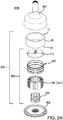
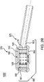
- FIGS 2A-2C show an illustrative showerhead filter device 1000 comprising a filter device housing 600 receiving the filter arrangement 575, the housing having a hollow handle 603 including a device housing inlet wherein fluid enters the device, a first portion 601, and a second portion 602 including the device outlet, wherein the housing defines a fluid flow path between the inlet and the outlet with the filter arrangement across the fluid flow path.
- FIGS 3A-3C show an illustrative faucet head filter device 1000' comprising a filter device housing 600' receiving the filter arrangement 575, the housing having a first portion 601' including the device housing fluid inlet and a second portion 602' including the device housing outlet, wherein the housing defines a fluid flow path between the inlet and the outlet with the filter arrangement across the fluid flow path.
- the host filter can include either an outer cage or an inner core, or can lack both an outer cage and an inner core.
- Figures 4A , 4B , 5A , and 5B show another host filter 500' similar to the host filter 500, but without an outer cage.
- illustrated host filter 500' comprises a first end cap 510 (having an outer diameter OD), and an inner core 530, and a porous fibrous hollow cylindrical host filter 550 comprising a porous fibrous hollow cylindrical host filter element 551, and the filter arrangement 575' comprises the host filter 500' and the prefiltration element 10.
- FIGS 4A-4B show another illustrative showerhead filter device 1001 comprising a filter device housing 600 receiving the filter arrangement 575', the housing having a hollow handle 603 including a device housing inlet wherein fluid enters the device, a first portion 601, and a second portion 602 including the device outlet, wherein the housing defines a fluid flow path between the inlet and the outlet with the filter arrangement across the fluid flow path.
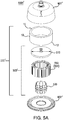
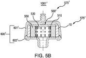
- FIGS 5A-5B show another illustrative faucet head filter device 1001' comprising a filter device housing 600' receiving the filter arrangement 575', the housing having a first portion 601' including a fluid inlet wherein fluid enters the device, and a second portion 602' including the device outlet, wherein the housing defines a fluid flow path between the inlet and the outlet with the filter arrangement across the fluid flow path.
- a prefiltration filter element can have any suitable pore structure as long as it does not significantly affect the liquid flow (e.g., water flow) characteristics of the host filter (which can also have any suitable pore structure).
- the pore structure of the prefiltration element e.g., a pore size (for example, as evidenced by bubble point, or by K L as described in, for example, U.S. Patent 4,340,479 , or evidenced by capillary condensation flow porometry), a pore rating, a pore diameter (e.g., when characterized using the modified OSU F2 test as described in, for example, U.S. Patent 4,925,572 ), or removal rating that reduces or allows the passage therethrough of one or more materials of interest as the fluid is passed through the element, is larger than that of the host filter.
- the host filter can include additional elements, layers, or components, that can have different structures and/or functions, e.g., at least one of any one or more of the following: support, drainage, spacing and cushioning.
- the host filter can also include at least one additional element such as a mesh and/or a screen.
- prefiltration elements are slightly flexible and slightly stretchable to provide a desired interference fit, with compression, such that the ends of the prefiltration elements do not need to be sealed or bonded to the host filter.
- temporary tooling such as, but not limited to, a guide dolly
- a guide dolly can be used as a lead-in to assist the slide over the widest part of the host filter.
- the host filter and prefiltration filter element are typically disposed in a housing comprising at least one inlet and at least one outlet and defining at least one fluid flow path between the inlet and the outlet, wherein the filter and prefiltration filter element is across the fluid flow path, to provide a filter device.
- the filter device and filter arrangement are sterilizable. Any housing of suitable shape and providing at least one inlet and at least one outlet may be employed.
- the housing can be fabricated from any suitable rigid impervious material, including any impervious thermoplastic material, which is compatible with the fluid being processed.
- the housing can be fabricated from a metal, such as stainless steel, or from a polymer.
- the housing is a polymer, such as an acrylic, polypropylene, polystyrene, or a polycarbonated resin.
- This example demonstrates the improved result using a prefiltration filter element with a host filter compared to the host filter without the prefiltration filter element.
- Host filters comprising porous fibrous hollow cylindrical filter elements with end caps, outer cases and inner cores; and filter housings, are produced as generally described in U.S. Patent 9,745,206 .
- the host filters are arranged on filter device housing portions including the filter device outlets.
- Prefiltration filter elements are produced by melt-blowing, cut to length, and compress fit over the widest diameter (the upper endcap) of the host filter by sliding the prefiltration element over a guide dolly on top of the host filter, and subsequently removing the guide dolly.
- the prefiltration filter elements fully cover the exposed upstream area or surface area of the host filter (i.e., covering the exposed upstream area of the outer cages) such that there is no bypassing of the host filter.
- the thickness of the prefiltration filter element (about 5 mm) does not exceed any constraints of the housing into which the host filter fits or is encapsulated into. No additional sealing, bonding, or retaining (e.g., adhesive, melting, or clips) is utilized. The housing does not contact the outer surface of the prefiltration element.
- the porosity of the prefiltration filter element is greater than that of the host filter.
- filter devices including prefiltration filter elements exhibit over twice the throughput over controls to the same degree of blockage (clean vs. end of life flowrate at a fixed inlet pressure).
Landscapes
- Chemical Kinetics & Catalysis (AREA)
- Chemical & Material Sciences (AREA)
- Engineering & Computer Science (AREA)
- Water Supply & Treatment (AREA)
- Public Health (AREA)
- Health & Medical Sciences (AREA)
- Epidemiology (AREA)
- General Health & Medical Sciences (AREA)
- Geometry (AREA)
- Physics & Mathematics (AREA)
- Separation Using Semi-Permeable Membranes (AREA)
- Domestic Plumbing Installations (AREA)
- Bathtubs, Showers, And Their Attachments (AREA)
- Filtration Of Liquid (AREA)
Abstract
Description
- Porous filters can be rated by their dirt holding capacity, and can be discarded as they approach, or reach, that capacity. In some situations, the filter device containing the porous filter is also discarded. While the dirt holding capacity may be increased by increasing the amount of filter material and/or changing the filter configuration, this may result in increased cost and/or may result in an undesirably large footprint for the filter device.
- The present invention provides for ameliorating at least some of the disadvantages of the prior art. These and other advantages of the present invention will be apparent from the description as set forth below.
- An embodiment of the invention provides a filter arrangement comprising a host filter comprising (a) a hollow cylindrical porous host filter element having a first end and a second end; (b) a first end cap arranged at the first end or the second end of the hollow cylindrical porous host filter element, the first end cap having an outer diameter; and, (c) an outer surface; the filter arrangement further comprising (d) a porous fibrous hollow cylindrical prefiltration element compression fit on the outer diameter of the first end cap, and covering the exposed outer surface of the host filter.
- A filter device according to another embodiment of the invention comprises an embodiment of the filter arrangement located in a housing having an inlet and an outlet and defining a fluid flow path between the inlet and the outlet, wherein the filter arrangement is arranged in the housing across the fluid flow path, such that undesirable material is removed from fluid as the fluid passes through the filter device. Preferably, the filter device comprises a point of use shower head device or a point of use faucet head device, and the host filter comprises a sterilizing grade water filter.
- In another embodiment, a method of producing a filter arrangement is provided, the method comprising compression fitting a porous fibrous hollow cylindrical prefiltration element over a host filter comprising (a) a hollow cylindrical porous host filter element having a first end and a second end; (b) a first end cap arranged at the first end or the second end of the hollow cylindrical porous host filter element, the first end cap having an outer diameter; and, (c) an outer surface; such that the prefiltration element is compression fit on the outer diameter of the first end cap, and covers the exposed outer surface of the host filter.
- An embodiment of processing fluid according to an embodiment of the invention comprising passing fluid through a filter arrangement comprising a porous fibrous hollow cylindrical prefiltration element and a host filter, wherein the porous fibrous hollow cylindrical prefiltration element is compression fitted on the host filter, and removing undesirable material from fluid as the fluid passes through the fluid arrangement. Preferred embodiments of the method comprise passing water through a point of use shower head device or a point of use faucet head device, wherein the host filter comprises a sterilizing grade water filter, and dispensing sterile water from the device.
-
-
Figure 1A shows a top isometric view of a prefiltration filter element according to an embodiment of the invention;Figure 1B shows a top isometric view of an assembled host filter, including a top end cap and an outer cage surrounding the host filter;Figure 1C shows a side view of the assembled host filter shown inFigure 1B; Figure 1D shows a top isometric view of filter arrangement comprising prefiltration filter element shown inFigure 1A compress fitted over the top end cap of the host filter as shown inFigure 1B; and Figure 1E shows a side view of the filter arrangement shown in Figure ID. -
Figure 2A is an exploded top isometric view of a showerhead filter device comprising a filter arrangement comprising a prefiltration filter element that can be compress fit over a host filter (comprising a host filter element between an inner core and an outer cage, and a top end cap sealed to the outer cage and the filter element and the inner core) arranged in a filter housing according to an embodiment of the invention,Figure 2B is a side cross section view of the assembled filter arrangement; andFigure 2C is a bottom view of the filter device shown inFigure 2A . -
Figure 3A is an exploded top isometric view of a faucet head filter device comprising a filter arrangement comprising a prefiltration filter element that can be compress fit over a host filter (comprising a host filter element between an inner core and an outer cage, and a top end cap sealed to the outer cage and the filter element and inner core) arranged in a filter housing according to an embodiment of the invention,Figure 3B is a side cross section view of the assembled filter arrangement, andFigure 3C is a bottom view of the filter device shown inFigure 3A . -
Figure 4A is an exploded top isometric view of a showerhead filter device comprising a filter arrangement comprising a prefiltration filter element that can be compress fit over a host filter (comprising a host filter element between having an inner core, and a top end cap sealed to the filter element and the inner core) arranged in a filter housing according to another embodiment of the invention, andFigure 4B is a side cross section view of the assembled filter arrangement. -
Figure 5A is an exploded top isometric view of a faucet head filter device comprising a filter arrangement comprising a prefiltration filter element that can be compress fit over a host filter (comprising a host filter element between having an inner core, and a top end cap sealed to the filter element and the inner core) arranged in a filter housing according to another embodiment of the invention, andFigure 5B is a side cross section view of the assembled filter arrangement. - In accordance with an embodiment of the invention, a filter arrangement is provided comprising a host filter comprising (a) a hollow cylindrical porous host filter element having a first end and a second end; (b) a first end cap arranged at the first end or the second end of the hollow cylindrical porous host filter element, the first end cap having an outer diameter; and, (c) an outer surface; the filter arrangement further comprising (d) a porous fibrous hollow cylindrical prefiltration element compression fit on the outer diameter of the first end cap, and covering the exposed outer surface of the host filter.
- In some embodiments, the prefiltration filter element covers the outer surface of an outer cage of the host filter. In other embodiments, the prefiltration filter element covers the upstream surface of the hollow cylindrical porous host filter element.
- In an embodiment of the filter arrangement, the host filter includes an outer cage surrounding the hollow cylindrical porous host filter element, the outer cage having an external surface providing the outer surface of the host filter. In another embodiment of the filter device, the hollow cylindrical porous host filter element has an upstream surface providing the outer surface of the host filter.
- A filter device according to an embodiment of the invention comprises an embodiment of the filter arrangement located in a housing having an inlet and an outlet and defining a fluid flow path between the inlet and the outlet, wherein the filter arrangement is arranged in the housing across the fluid flow path, such that undesirable material is removed from fluid as the fluid passes through the filter device. Preferably, the filter device comprises a point of use shower head device or a point of use faucet head device, and the host filter comprises a sterilizing grade water filter.
- In another embodiment, a method of producing a filter arrangement is provided, the method comprising compression fitting a porous fibrous hollow cylindrical prefiltration element over a host filter comprising (a) a hollow cylindrical porous host filter element having a first end and a second end; (b) a first end cap arranged at the first end or the second end of the hollow cylindrical porous host filter element, the first end cap having an outer diameter; and, (c) an outer surface; such that the prefiltration element is compression fit on the outer diameter of the first end cap, and covers the exposed outer surface of the host filter.
- An embodiment of processing fluid according to an embodiment of the invention comprising passing fluid through a filter arrangement comprising a porous fibrous hollow cylindrical prefiltration element and a host filter, wherein the porous fibrous hollow cylindrical prefiltration element is compression fitted on the host filter, and removing undesirable material from fluid as the fluid passes through the fluid arrangement. Preferred embodiments of the method comprise passing water through a point of use shower head device or a point of use faucet head device, wherein the host filter comprises a sterilizing grade water filter, and dispensing sterile water from the device.
- Advantageously, the use of a prefiltration filter element can increase the life and/or dirt holding capacity of the host filter. Moreover, the prefiltration filter element can be produced and used at a fraction of the cost of the host filter, and may increase the filter life to blockage by several fold with little effect on the pressure drop across the prefiltration filter element and host filter.
- Prefiltration filter elements, which comprise porous fibrous hollow cylindrical elements, can be produced by a variety of processes, including meltblowing. They can comprise woven or nonwoven material.
- If desired, the prefiltration filter element can include multiple layers of different fiber diameters and/or densities and/or pore structures that provide different filtration efficiencies.
- Prefiltration filter elements can be used with filters with and without outer cages, fully covering the exposed upstream area or surface area of the host filter or host filter outer cage such that there is no bypassing of the host filter.
- In accordance with embodiments of the invention, the prefiltration filter element can be used with a variety of porous hollow cylindrical host filters and porous hollow cylindrical host filter elements (especially porous fibrous hollow cylindrical host filters and host filter elements) and filter devices including such filters and filter elements. One example of a suitable filter and filter device is disclosed in
U.S. Patent 9,745,206 - Each of the components of the invention will now be described in more detail below, wherein like components have like reference numbers.
-
Figure 1A shows an embodiment of aprefiltration filter element 10 comprising a porous fibrous hollow cylindrical element for use with a host filter, the prefiltration filter element having afirst end 10, asecond end 11, and a thickness T. -
Figures 1B, 1C ,2A ,2B ,3A and3B show anillustrative host filter 500. UsingFigures 2A and3A for reference, anillustrative host filter 500 comprises a first end cap 510 (having an outer diameter OD), anouter cage 520 having an outer surface, aninner core 530, and a porous fibrous hollowcylindrical host filter 550 comprising a porous fibrous hollow cylindricalhost filter element 551. While the host filter illustrated inFigures 1B, 1C ,2A ,2B ,3A and3B includes an outer cage and an inner core, the cage and core are optional, and the host filter can include either an outer cage or an inner core, or can lack both an outer cage and an inner core. -
Figure 1B shows an isometric view, andFigure 1C shows a side view, of thehost filter 500 without theprefiltration element 10, andFigure 1D shows an isometric view, andFigure 1E shows a side view, of an embodiment of thefilter arrangement 575, wherein theprefiltration filter element 10 is compression fit over the filter (i.e., compression fit over the OD of first end cap 510), and covering the exposed outer surface of theouter cage 520, such that there is no bypassing of the host filter during use. - Thus, with respect to the filter device housing,
Figures 2A-2C show an illustrativeshowerhead filter device 1000 comprising afilter device housing 600 receiving thefilter arrangement 575, the housing having ahollow handle 603 including a device housing inlet wherein fluid enters the device, afirst portion 601, and asecond portion 602 including the device outlet, wherein the housing defines a fluid flow path between the inlet and the outlet with the filter arrangement across the fluid flow path. -
Figures 3A-3C show an illustrative faucet head filter device 1000' comprising a filter device housing 600' receiving thefilter arrangement 575, the housing having afirst portion 601' including the device housing fluid inlet and asecond portion 602' including the device housing outlet, wherein the housing defines a fluid flow path between the inlet and the outlet with the filter arrangement across the fluid flow path. - As noted above, the host filter can include either an outer cage or an inner core, or can lack both an outer cage and an inner core. For example,
Figures 4A ,4B ,5A , and5B show another host filter 500' similar to thehost filter 500, but without an outer cage. Thus, illustrated host filter 500' comprises a first end cap 510 (having an outer diameter OD), and aninner core 530, and a porous fibrous hollowcylindrical host filter 550 comprising a porous fibrous hollow cylindricalhost filter element 551, and thefilter arrangement 575' comprises the host filter 500' and theprefiltration element 10. -
Figures 4A-4B show another illustrativeshowerhead filter device 1001 comprising afilter device housing 600 receiving thefilter arrangement 575', the housing having ahollow handle 603 including a device housing inlet wherein fluid enters the device, afirst portion 601, and asecond portion 602 including the device outlet, wherein the housing defines a fluid flow path between the inlet and the outlet with the filter arrangement across the fluid flow path. -
Figures 5A-5B show another illustrative faucet head filter device 1001' comprising a filter device housing 600' receiving thefilter arrangement 575', the housing having afirst portion 601' including a fluid inlet wherein fluid enters the device, and asecond portion 602' including the device outlet, wherein the housing defines a fluid flow path between the inlet and the outlet with the filter arrangement across the fluid flow path. - A prefiltration filter element can have any suitable pore structure as long as it does not significantly affect the liquid flow (e.g., water flow) characteristics of the host filter (which can also have any suitable pore structure). Typically, the pore structure of the prefiltration element, e.g., a pore size (for example, as evidenced by bubble point, or by KL as described in, for example,
U.S. Patent 4,340,479 , or evidenced by capillary condensation flow porometry), a pore rating, a pore diameter (e.g., when characterized using the modified OSU F2 test as described in, for example,U.S. Patent 4,925,572 ), or removal rating that reduces or allows the passage therethrough of one or more materials of interest as the fluid is passed through the element, is larger than that of the host filter. - The host filter can include additional elements, layers, or components, that can have different structures and/or functions, e.g., at least one of any one or more of the following: support, drainage, spacing and cushioning. Illustratively, the host filter can also include at least one additional element such as a mesh and/or a screen.
- Typically, prefiltration elements are slightly flexible and slightly stretchable to provide a desired interference fit, with compression, such that the ends of the prefiltration elements do not need to be sealed or bonded to the host filter. If desired, temporary tooling (such as, but not limited to, a guide dolly) can be used as a lead-in to assist the slide over the widest part of the host filter.
- The host filter and prefiltration filter element are typically disposed in a housing comprising at least one inlet and at least one outlet and defining at least one fluid flow path between the inlet and the outlet, wherein the filter and prefiltration filter element is across the fluid flow path, to provide a filter device. Preferably, the filter device and filter arrangement are sterilizable. Any housing of suitable shape and providing at least one inlet and at least one outlet may be employed.
- The housing can be fabricated from any suitable rigid impervious material, including any impervious thermoplastic material, which is compatible with the fluid being processed. For example, the housing can be fabricated from a metal, such as stainless steel, or from a polymer. In a preferred embodiment, the housing is a polymer, such as an acrylic, polypropylene, polystyrene, or a polycarbonated resin.
- The following example(s) further illustrate the invention but, of course, should not be construed as in any way limiting its scope.
- This example demonstrates the improved result using a prefiltration filter element with a host filter compared to the host filter without the prefiltration filter element.
- Host filters comprising porous fibrous hollow cylindrical filter elements with end caps, outer cases and inner cores; and filter housings, are produced as generally described in
U.S. Patent 9,745,206 - Prefiltration filter elements are produced by melt-blowing, cut to length, and compress fit over the widest diameter (the upper endcap) of the host filter by sliding the prefiltration element over a guide dolly on top of the host filter, and subsequently removing the guide dolly. The prefiltration filter elements fully cover the exposed upstream area or surface area of the host filter (i.e., covering the exposed upstream area of the outer cages) such that there is no bypassing of the host filter.
- The thickness of the prefiltration filter element (about 5 mm) does not exceed any constraints of the housing into which the host filter fits or is encapsulated into. No additional sealing, bonding, or retaining (e.g., adhesive, melting, or clips) is utilized. The housing does not contact the outer surface of the prefiltration element.
- The porosity of the prefiltration filter element is greater than that of the host filter.
- After dust loading, about a 5-10% flow loss is observed in filter devices including prefiltration filter elements, in contrast with about a 50% loss in the controls.
- Additionally, filter devices including prefiltration filter elements exhibit over twice the throughput over controls to the same degree of blockage (clean vs. end of life flowrate at a fixed inlet pressure).
- All references, including publications, patent applications, and patents, cited herein are hereby incorporated by reference to the same extent as if each reference were individually and specifically indicated to be incorporated by reference and were set forth in its entirety herein.
- The use of the terms "a" and "an" and "the" and "at least one" and similar referents in the context of describing the invention (especially in the context of the following claims) are to be construed to cover both the singular and the plural, unless otherwise indicated herein or clearly contradicted by context. The use of the term "at least one" followed by a list of one or more items (for example, "at least one of A and B") is to be construed to mean one item selected from the listed items (A or B) or any combination of two or more of the listed items (A and B), unless otherwise indicated herein or clearly contradicted by context. The terms "comprising," "having," "including," and "containing" are to be construed as open-ended terms (i.e., meaning "including, but not limited to,") unless otherwise noted. Recitation of ranges of values herein are merely intended to serve as a shorthand method of referring individually to each separate value falling within the range, unless otherwise indicated herein, and each separate value is incorporated into the specification as if it were individually recited herein. All methods described herein can be performed in any suitable order unless otherwise indicated herein or otherwise clearly contradicted by context. The use of any and all examples, or exemplary language (e.g., "such as") provided herein, is intended merely to better illuminate the invention and does not pose a limitation on the scope of the invention unless otherwise claimed. No language in the specification should be construed as indicating any non-claimed element as essential to the practice of the invention.
- Preferred embodiments of this invention are described herein, including the best mode known to the inventors for carrying out the invention. Variations of those preferred embodiments may become apparent to those of ordinary skill in the art upon reading the foregoing description. The inventors expect skilled artisans to employ such variations as appropriate, and the inventors intend for the invention to be practiced otherwise than as specifically described herein. Accordingly, this invention includes all modifications and equivalents of the subject matter recited in the claims appended hereto as permitted by applicable law. Moreover, any combination of the above-described elements in all possible variations thereof is encompassed by the invention unless otherwise indicated herein or otherwise clearly contradicted by context.
Claims (7)
- A filter arrangement comprising:a host filter comprising(a) a hollow cylindrical porous host filter element having a first end and a second end;(b) a first end cap arranged at the first end or the second end of the hollow cylindrical porous host filter element, the first end cap having an outer diameter; and,(c) an outer surface;the filter arrangement further comprising
(d) a porous fibrous hollow cylindrical prefiltration element compression fit on the outer diameter of the first end cap, and covering exposed outer surface of the host filter. - The filter arrangement of claim 1, wherein the host filter includes an outer cage surrounding the hollow cylindrical porous host filter element, the outer cage having an external surface providing the outer surface of the host filter.
- The filter arrangement of claim 1, wherein the hollow cylindrical porous host filter element has an upstream surface providing the outer surface of the host filter.
- A filter device comprising a housing having an inlet and an outlet and defining a fluid flow path between the inlet and the outlet, and a filter arrangement comprising a host filter comprising (a) a hollow cylindrical porous host filter element having a first end and a second end; (b) a first end cap arranged at the first end or the second end of the hollow cylindrical porous host filter element, the first end cap having an outer diameter; and, (c) an outer surface; and, (d) a porous fibrous hollow cylindrical prefiltration element compression fit on the outer diameter of the first end cap, and covering exposed outer surface of the host filter, wherein the filter arrangement is arranged across the fluid flow path.
- A method of processing fluid, the method comprising passing fluid through the filter device of claim 4.
- The method of claim 5, wherein the filter device comprises a point of use shower head device or a point of use faucet head device, and the host filter comprises a sterilizing grade water filter, and the method includes dispensing sterile water from the device.
- A method of producing a filter arrangement, the method comprising:obtaining a host filter comprising (a) a hollow cylindrical porous host filter element having a first end and a second end; (b) a first end cap arranged at the first end or the second end of the hollow cylindrical porous host filter element, the first end cap having an outer diameter; and, (c) an outer surface; and,compression fitting a porous fibrous hollow cylindrical prefiltration element on the outer diameter of the first end cap, and covering the exposed outer surface of the host filter.
Applications Claiming Priority (1)
| Application Number | Priority Date | Filing Date | Title |
|---|---|---|---|
| US16/909,239 US12076671B2 (en) | 2020-06-23 | 2020-06-23 | Filter arrangement including prefiltration filter element and filter device |
Publications (2)
| Publication Number | Publication Date |
|---|---|
| EP3928849A1 true EP3928849A1 (en) | 2021-12-29 |
| EP3928849B1 EP3928849B1 (en) | 2025-01-01 |
Family
ID=76553549
Family Applications (1)
| Application Number | Title | Priority Date | Filing Date |
|---|---|---|---|
| EP21180709.4A Active EP3928849B1 (en) | 2020-06-23 | 2021-06-21 | Filter arrangement including prefiltration filter element and filter device |
Country Status (8)
| Country | Link |
|---|---|
| US (1) | US12076671B2 (en) |
| EP (1) | EP3928849B1 (en) |
| JP (1) | JP2022002840A (en) |
| KR (1) | KR20210158352A (en) |
| CN (1) | CN113828048A (en) |
| AU (1) | AU2021204234B2 (en) |
| CA (1) | CA3122838C (en) |
| ES (1) | ES3014715T3 (en) |
Families Citing this family (5)
| Publication number | Priority date | Publication date | Assignee | Title |
|---|---|---|---|---|
| USD955527S1 (en) * | 2021-08-05 | 2022-06-21 | Hongli Lin | Shower head |
| CN114542732B (en) * | 2022-02-24 | 2024-09-24 | 厦门泉加乐新材料股份有限公司 | Vertical dual-purpose water outlet piece |
| KR102454237B1 (en) * | 2022-06-29 | 2022-10-14 | 주식회사 블루인더스 | Shower head with filter |
| KR102505839B1 (en) | 2022-06-30 | 2023-03-02 | 주식회사 블루인더스 | Manufacturing Method of Bending Filter |
| CN120794239A (en) * | 2025-07-25 | 2025-10-17 | 东莞市倍益清环保科技有限公司 | Filter element of shower |
Citations (10)
| Publication number | Priority date | Publication date | Assignee | Title |
|---|---|---|---|---|
| GB1057317A (en) * | 1962-10-27 | 1967-02-01 | Knecht Alfred | Filtering device |
| DE1536922A1 (en) * | 1966-07-23 | 1970-02-12 | Stone Filter Co Inc | filter |
| US4340479A (en) | 1978-05-15 | 1982-07-20 | Pall Corporation | Process for preparing hydrophilic polyamide membrane filter media and product |
| US4925572A (en) | 1987-10-20 | 1990-05-15 | Pall Corporation | Device and method for depletion of the leukocyte content of blood and blood components |
| GB2261830A (en) * | 1991-11-26 | 1993-06-02 | Process Scient Innovations | Gas filter |
| US5980759A (en) * | 1993-10-19 | 1999-11-09 | Millipore Corporation | Dual media filter cartridge construction |
| US7087166B1 (en) * | 2001-10-01 | 2006-08-08 | Entegris, Inc. | Filter element and filter device having replaceable filter |
| DE102011010667A1 (en) * | 2011-02-08 | 2012-08-09 | Mann + Hummel Gmbh | Filter arrangement and filtering method |
| US9745206B2 (en) | 2010-09-08 | 2017-08-29 | Pall Corporation | Outlet for shower or faucet head |
| DE202017107401U1 (en) * | 2017-04-25 | 2017-12-21 | Fujian Xihe Sanitary Ware Technology Co., Ltd | One-directional, filtering shower head |
Family Cites Families (13)
| Publication number | Priority date | Publication date | Assignee | Title |
|---|---|---|---|---|
| JPS63175685A (en) | 1987-01-14 | 1988-07-20 | Iwasaki Electric Co Ltd | water purifier |
| US5328609A (en) * | 1992-11-16 | 1994-07-12 | Magnusson Jon H | Multi-stage radial flow filtration system |
| US5415676A (en) | 1993-08-16 | 1995-05-16 | Donaldson Company, Inc. | Mist collector cartridge |
| US5935426A (en) * | 1997-08-08 | 1999-08-10 | Teledyne Industries, Inc., A California Corporation | Water treatment device with volumetric and time monitoring features |
| US6096197A (en) * | 1997-12-11 | 2000-08-01 | Hughes; Douglass E. | Shower filter for chlorine removal and scale deposit prevention |
| DE10115633A1 (en) | 2001-03-23 | 2002-09-26 | Fuma Tech Gmbh | Shower water filter cartridge incorporates numerous porous hollow fibres |
| JP2003038916A (en) | 2001-07-17 | 2003-02-12 | Millipore Corp | Filter element and filter apparatus having exchangable filter |
| JP2004000956A (en) | 2002-04-22 | 2004-01-08 | Kitz Corp | Water purification cartridge having built-in tap |
| US20030205518A1 (en) | 2002-05-06 | 2003-11-06 | Vanderkooi Karen J. | Water filter assembly |
| US6962660B2 (en) * | 2002-09-25 | 2005-11-08 | Master Spas, Inc. | Fluid filter system with secondary flow path for augmented filtration |
| US8323384B2 (en) | 2009-12-18 | 2012-12-04 | Clark Filter, Inc. | Air filter with extended life |
| US20120055888A1 (en) | 2010-09-08 | 2012-03-08 | Pall Europe Limited | Outlet for shower or faucet head |
| DE102013008392A1 (en) * | 2013-05-17 | 2014-11-20 | Mann + Hummel Gmbh | Air filters for the interior air of cabins of vehicles, agricultural, construction and working machines |
-
2020
- 2020-06-23 US US16/909,239 patent/US12076671B2/en active Active
-
2021
- 2021-06-21 EP EP21180709.4A patent/EP3928849B1/en active Active
- 2021-06-21 ES ES21180709T patent/ES3014715T3/en active Active
- 2021-06-22 JP JP2021103209A patent/JP2022002840A/en active Pending
- 2021-06-22 CA CA3122838A patent/CA3122838C/en active Active
- 2021-06-23 CN CN202110695213.0A patent/CN113828048A/en active Pending
- 2021-06-23 AU AU2021204234A patent/AU2021204234B2/en active Active
- 2021-06-23 KR KR1020210081642A patent/KR20210158352A/en not_active Ceased
Patent Citations (11)
| Publication number | Priority date | Publication date | Assignee | Title |
|---|---|---|---|---|
| GB1057317A (en) * | 1962-10-27 | 1967-02-01 | Knecht Alfred | Filtering device |
| DE1536922A1 (en) * | 1966-07-23 | 1970-02-12 | Stone Filter Co Inc | filter |
| US4340479A (en) | 1978-05-15 | 1982-07-20 | Pall Corporation | Process for preparing hydrophilic polyamide membrane filter media and product |
| US4340479B1 (en) | 1978-05-15 | 1996-08-27 | Pall Corp | Process for preparing hydrophilic polyamide membrane filter media and product |
| US4925572A (en) | 1987-10-20 | 1990-05-15 | Pall Corporation | Device and method for depletion of the leukocyte content of blood and blood components |
| GB2261830A (en) * | 1991-11-26 | 1993-06-02 | Process Scient Innovations | Gas filter |
| US5980759A (en) * | 1993-10-19 | 1999-11-09 | Millipore Corporation | Dual media filter cartridge construction |
| US7087166B1 (en) * | 2001-10-01 | 2006-08-08 | Entegris, Inc. | Filter element and filter device having replaceable filter |
| US9745206B2 (en) | 2010-09-08 | 2017-08-29 | Pall Corporation | Outlet for shower or faucet head |
| DE102011010667A1 (en) * | 2011-02-08 | 2012-08-09 | Mann + Hummel Gmbh | Filter arrangement and filtering method |
| DE202017107401U1 (en) * | 2017-04-25 | 2017-12-21 | Fujian Xihe Sanitary Ware Technology Co., Ltd | One-directional, filtering shower head |
Also Published As
| Publication number | Publication date |
|---|---|
| US20210394094A1 (en) | 2021-12-23 |
| US12076671B2 (en) | 2024-09-03 |
| CN113828048A (en) | 2021-12-24 |
| AU2021204234B2 (en) | 2022-12-01 |
| CA3122838C (en) | 2023-05-16 |
| ES3014715T3 (en) | 2025-04-24 |
| JP2022002840A (en) | 2022-01-11 |
| CA3122838A1 (en) | 2021-12-23 |
| AU2021204234A1 (en) | 2022-01-20 |
| EP3928849B1 (en) | 2025-01-01 |
| KR20210158352A (en) | 2021-12-30 |
Similar Documents
| Publication | Publication Date | Title |
|---|---|---|
| CA3122838C (en) | Filter arrangement including prefiltration filter element and filter device | |
| CN107530612B (en) | Air pressure filters and filter elements | |
| US6986842B2 (en) | Filter element with foam girdle to secure pleats and method of forming same | |
| EP3458174B1 (en) | Filter assembly and method for filtration | |
| EP0913183A1 (en) | Filter drainage layer attachment | |
| CA2886303C (en) | Filter elements and methods for filtering fluids | |
| JP2006501058A (en) | Filter element having filter media with multilayer pleated support | |
| EP3124094A1 (en) | Filter assembly | |
| US7153425B2 (en) | Process and filter for filtering a slurry | |
| EP1214131A1 (en) | Filter elements and filtering methods | |
| WO2011126136A1 (en) | Filter element and filter device | |
| GB2084897A (en) | Filter unit | |
| CN109069950B (en) | Filter element for filtering a fluid through a filter element, coalescing filter, compressed air filtration system, use of a filter element and method for producing a coalescing filter | |
| US20180015394A1 (en) | Water filter | |
| JP6277456B2 (en) | Filter element | |
| US10918976B2 (en) | Support and drainage material, filter, and method of use | |
| WO2006044630A2 (en) | Contaminated liquids filtering apparatus | |
| JP2024515874A (en) | FILTER CARTRIDGE, FILTER DEVICE, AND METHODS | |
| EP3643381A1 (en) | Support and drainage material, filter, and method of use | |
| WO2008115494A1 (en) | Liquid filter assembly | |
| WO2019040867A1 (en) | Wedge shaped filters, assembly and method for filtration and coalescing | |
| US10632402B1 (en) | Support and drainage material, filter, and method of use | |
| CN111085023B (en) | Support and drainage material, filter and method of use | |
| WO2001085301A1 (en) | Filter element with foam girdle to secure pleats | |
| JP2003038916A (en) | Filter element and filter apparatus having exchangable filter |
Legal Events
| Date | Code | Title | Description |
|---|---|---|---|
| PUAI | Public reference made under article 153(3) epc to a published international application that has entered the european phase |
Free format text: ORIGINAL CODE: 0009012 |
|
| STAA | Information on the status of an ep patent application or granted ep patent |
Free format text: STATUS: THE APPLICATION HAS BEEN PUBLISHED |
|
| AK | Designated contracting states |
Kind code of ref document: A1 Designated state(s): AL AT BE BG CH CY CZ DE DK EE ES FI FR GB GR HR HU IE IS IT LI LT LU LV MC MK MT NL NO PL PT RO RS SE SI SK SM TR |
|
| B565 | Issuance of search results under rule 164(2) epc |
Effective date: 20211013 |
|
| STAA | Information on the status of an ep patent application or granted ep patent |
Free format text: STATUS: REQUEST FOR EXAMINATION WAS MADE |
|
| 17P | Request for examination filed |
Effective date: 20220622 |
|
| RBV | Designated contracting states (corrected) |
Designated state(s): AL AT BE BG CH CY CZ DE DK EE ES FI FR GB GR HR HU IE IS IT LI LT LU LV MC MK MT NL NO PL PT RO RS SE SI SK SM TR |
|
| P01 | Opt-out of the competence of the unified patent court (upc) registered |
Effective date: 20230530 |
|
| STAA | Information on the status of an ep patent application or granted ep patent |
Free format text: STATUS: EXAMINATION IS IN PROGRESS |
|
| 17Q | First examination report despatched |
Effective date: 20230714 |
|
| GRAP | Despatch of communication of intention to grant a patent |
Free format text: ORIGINAL CODE: EPIDOSNIGR1 |
|
| STAA | Information on the status of an ep patent application or granted ep patent |
Free format text: STATUS: GRANT OF PATENT IS INTENDED |
|
| INTG | Intention to grant announced |
Effective date: 20240625 |
|
| RAP1 | Party data changed (applicant data changed or rights of an application transferred) |
Owner name: CYTIVA US LLC |
|
| GRAJ | Information related to disapproval of communication of intention to grant by the applicant or resumption of examination proceedings by the epo deleted |
Free format text: ORIGINAL CODE: EPIDOSDIGR1 |
|
| STAA | Information on the status of an ep patent application or granted ep patent |
Free format text: STATUS: EXAMINATION IS IN PROGRESS |
|
| GRAS | Grant fee paid |
Free format text: ORIGINAL CODE: EPIDOSNIGR3 |
|
| STAA | Information on the status of an ep patent application or granted ep patent |
Free format text: STATUS: GRANT OF PATENT IS INTENDED |
|
| GRAP | Despatch of communication of intention to grant a patent |
Free format text: ORIGINAL CODE: EPIDOSNIGR1 |
|
| INTC | Intention to grant announced (deleted) | ||
| INTG | Intention to grant announced |
Effective date: 20241029 |
|
| GRAA | (expected) grant |
Free format text: ORIGINAL CODE: 0009210 |
|
| STAA | Information on the status of an ep patent application or granted ep patent |
Free format text: STATUS: THE PATENT HAS BEEN GRANTED |
|
| AK | Designated contracting states |
Kind code of ref document: B1 Designated state(s): AL AT BE BG CH CY CZ DE DK EE ES FI FR GB GR HR HU IE IS IT LI LT LU LV MC MK MT NL NO PL PT RO RS SE SI SK SM TR |
|
| REG | Reference to a national code |
Ref country code: GB Ref legal event code: FG4D |
|
| REG | Reference to a national code |
Ref country code: CH Ref legal event code: EP |
|
| REG | Reference to a national code |
Ref country code: DE Ref legal event code: R096 Ref document number: 602021024112 Country of ref document: DE |
|
| REG | Reference to a national code |
Ref country code: IE Ref legal event code: FG4D |
|
| REG | Reference to a national code |
Ref country code: ES Ref legal event code: FG2A Ref document number: 3014715 Country of ref document: ES Kind code of ref document: T3 Effective date: 20250424 |
|
| REG | Reference to a national code |
Ref country code: LT Ref legal event code: MG9D |
|
| REG | Reference to a national code |
Ref country code: NL Ref legal event code: MP Effective date: 20250101 |
|
| REG | Reference to a national code |
Ref country code: AT Ref legal event code: MK05 Ref document number: 1755664 Country of ref document: AT Kind code of ref document: T Effective date: 20250101 |
|
| PG25 | Lapsed in a contracting state [announced via postgrant information from national office to epo] |
Ref country code: NL Free format text: LAPSE BECAUSE OF FAILURE TO SUBMIT A TRANSLATION OF THE DESCRIPTION OR TO PAY THE FEE WITHIN THE PRESCRIBED TIME-LIMIT Effective date: 20250101 |
|
| PG25 | Lapsed in a contracting state [announced via postgrant information from national office to epo] |
Ref country code: FI Free format text: LAPSE BECAUSE OF FAILURE TO SUBMIT A TRANSLATION OF THE DESCRIPTION OR TO PAY THE FEE WITHIN THE PRESCRIBED TIME-LIMIT Effective date: 20250101 |
|
| PG25 | Lapsed in a contracting state [announced via postgrant information from national office to epo] |
Ref country code: PL Free format text: LAPSE BECAUSE OF FAILURE TO SUBMIT A TRANSLATION OF THE DESCRIPTION OR TO PAY THE FEE WITHIN THE PRESCRIBED TIME-LIMIT Effective date: 20250101 |
|
| PGFP | Annual fee paid to national office [announced via postgrant information from national office to epo] |
Ref country code: DE Payment date: 20250626 Year of fee payment: 5 |
|
| PGFP | Annual fee paid to national office [announced via postgrant information from national office to epo] |
Ref country code: GB Payment date: 20250618 Year of fee payment: 5 |
|
| PG25 | Lapsed in a contracting state [announced via postgrant information from national office to epo] |
Ref country code: NO Free format text: LAPSE BECAUSE OF FAILURE TO SUBMIT A TRANSLATION OF THE DESCRIPTION OR TO PAY THE FEE WITHIN THE PRESCRIBED TIME-LIMIT Effective date: 20250401 Ref country code: IS Free format text: LAPSE BECAUSE OF FAILURE TO SUBMIT A TRANSLATION OF THE DESCRIPTION OR TO PAY THE FEE WITHIN THE PRESCRIBED TIME-LIMIT Effective date: 20250501 |
|
| PG25 | Lapsed in a contracting state [announced via postgrant information from national office to epo] |
Ref country code: HR Free format text: LAPSE BECAUSE OF FAILURE TO SUBMIT A TRANSLATION OF THE DESCRIPTION OR TO PAY THE FEE WITHIN THE PRESCRIBED TIME-LIMIT Effective date: 20250101 |
|
| PG25 | Lapsed in a contracting state [announced via postgrant information from national office to epo] |
Ref country code: PT Free format text: LAPSE BECAUSE OF FAILURE TO SUBMIT A TRANSLATION OF THE DESCRIPTION OR TO PAY THE FEE WITHIN THE PRESCRIBED TIME-LIMIT Effective date: 20250502 Ref country code: LV Free format text: LAPSE BECAUSE OF FAILURE TO SUBMIT A TRANSLATION OF THE DESCRIPTION OR TO PAY THE FEE WITHIN THE PRESCRIBED TIME-LIMIT Effective date: 20250101 |
|
| PGFP | Annual fee paid to national office [announced via postgrant information from national office to epo] |
Ref country code: FR Payment date: 20250624 Year of fee payment: 5 |
|
| PG25 | Lapsed in a contracting state [announced via postgrant information from national office to epo] |
Ref country code: GR Free format text: LAPSE BECAUSE OF FAILURE TO SUBMIT A TRANSLATION OF THE DESCRIPTION OR TO PAY THE FEE WITHIN THE PRESCRIBED TIME-LIMIT Effective date: 20250402 Ref country code: BG Free format text: LAPSE BECAUSE OF FAILURE TO SUBMIT A TRANSLATION OF THE DESCRIPTION OR TO PAY THE FEE WITHIN THE PRESCRIBED TIME-LIMIT Effective date: 20250101 |
|
| PG25 | Lapsed in a contracting state [announced via postgrant information from national office to epo] |
Ref country code: AT Free format text: LAPSE BECAUSE OF FAILURE TO SUBMIT A TRANSLATION OF THE DESCRIPTION OR TO PAY THE FEE WITHIN THE PRESCRIBED TIME-LIMIT Effective date: 20250101 |
|
| PG25 | Lapsed in a contracting state [announced via postgrant information from national office to epo] |
Ref country code: CZ Free format text: LAPSE BECAUSE OF FAILURE TO SUBMIT A TRANSLATION OF THE DESCRIPTION OR TO PAY THE FEE WITHIN THE PRESCRIBED TIME-LIMIT Effective date: 20250101 |
|
| PG25 | Lapsed in a contracting state [announced via postgrant information from national office to epo] |
Ref country code: SE Free format text: LAPSE BECAUSE OF FAILURE TO SUBMIT A TRANSLATION OF THE DESCRIPTION OR TO PAY THE FEE WITHIN THE PRESCRIBED TIME-LIMIT Effective date: 20250101 |
|
| REG | Reference to a national code |
Ref country code: DE Ref legal event code: R097 Ref document number: 602021024112 Country of ref document: DE |
|
| PG25 | Lapsed in a contracting state [announced via postgrant information from national office to epo] |
Ref country code: SM Free format text: LAPSE BECAUSE OF FAILURE TO SUBMIT A TRANSLATION OF THE DESCRIPTION OR TO PAY THE FEE WITHIN THE PRESCRIBED TIME-LIMIT Effective date: 20250101 |
|
| PGFP | Annual fee paid to national office [announced via postgrant information from national office to epo] |
Ref country code: ES Payment date: 20250710 Year of fee payment: 5 |
|
| PG25 | Lapsed in a contracting state [announced via postgrant information from national office to epo] |
Ref country code: DK Free format text: LAPSE BECAUSE OF FAILURE TO SUBMIT A TRANSLATION OF THE DESCRIPTION OR TO PAY THE FEE WITHIN THE PRESCRIBED TIME-LIMIT Effective date: 20250101 |
|
| PGFP | Annual fee paid to national office [announced via postgrant information from national office to epo] |
Ref country code: IT Payment date: 20250623 Year of fee payment: 5 |
|
| PG25 | Lapsed in a contracting state [announced via postgrant information from national office to epo] |
Ref country code: EE Free format text: LAPSE BECAUSE OF FAILURE TO SUBMIT A TRANSLATION OF THE DESCRIPTION OR TO PAY THE FEE WITHIN THE PRESCRIBED TIME-LIMIT Effective date: 20250101 |
|
| PG25 | Lapsed in a contracting state [announced via postgrant information from national office to epo] |
Ref country code: RO Free format text: LAPSE BECAUSE OF FAILURE TO SUBMIT A TRANSLATION OF THE DESCRIPTION OR TO PAY THE FEE WITHIN THE PRESCRIBED TIME-LIMIT Effective date: 20250101 |
|
| PG25 | Lapsed in a contracting state [announced via postgrant information from national office to epo] |
Ref country code: SK Free format text: LAPSE BECAUSE OF FAILURE TO SUBMIT A TRANSLATION OF THE DESCRIPTION OR TO PAY THE FEE WITHIN THE PRESCRIBED TIME-LIMIT Effective date: 20250101 |
|
| PLBE | No opposition filed within time limit |
Free format text: ORIGINAL CODE: 0009261 |
|
| STAA | Information on the status of an ep patent application or granted ep patent |
Free format text: STATUS: NO OPPOSITION FILED WITHIN TIME LIMIT |
|
| REG | Reference to a national code |
Ref country code: CH Ref legal event code: L10 Free format text: ST27 STATUS EVENT CODE: U-0-0-L10-L00 (AS PROVIDED BY THE NATIONAL OFFICE) Effective date: 20251112 |
|
| 26N | No opposition filed |
Effective date: 20251002 |
|
| REG | Reference to a national code |
Ref country code: CH Ref legal event code: H13 Free format text: ST27 STATUS EVENT CODE: U-0-0-H10-H13 (AS PROVIDED BY THE NATIONAL OFFICE) Effective date: 20260127 |
|
| PG25 | Lapsed in a contracting state [announced via postgrant information from national office to epo] |
Ref country code: MC Free format text: LAPSE BECAUSE OF FAILURE TO SUBMIT A TRANSLATION OF THE DESCRIPTION OR TO PAY THE FEE WITHIN THE PRESCRIBED TIME-LIMIT Effective date: 20250101 |
|
| PG25 | Lapsed in a contracting state [announced via postgrant information from national office to epo] |
Ref country code: LU Free format text: LAPSE BECAUSE OF NON-PAYMENT OF DUE FEES Effective date: 20250621 |
|
| REG | Reference to a national code |
Ref country code: BE Ref legal event code: MM Effective date: 20250630 |
|
| PG25 | Lapsed in a contracting state [announced via postgrant information from national office to epo] |
Ref country code: IE Free format text: LAPSE BECAUSE OF NON-PAYMENT OF DUE FEES Effective date: 20250621 |
|
| PG25 | Lapsed in a contracting state [announced via postgrant information from national office to epo] |
Ref country code: BE Free format text: LAPSE BECAUSE OF NON-PAYMENT OF DUE FEES Effective date: 20250630 |
|
| PG25 | Lapsed in a contracting state [announced via postgrant information from national office to epo] |
Ref country code: CH Free format text: LAPSE BECAUSE OF NON-PAYMENT OF DUE FEES Effective date: 20250630 |