EP3928246B1 - Objektstandortbestimmung - Google Patents
Objektstandortbestimmung Download PDFInfo
- Publication number
- EP3928246B1 EP3928246B1 EP19708969.1A EP19708969A EP3928246B1 EP 3928246 B1 EP3928246 B1 EP 3928246B1 EP 19708969 A EP19708969 A EP 19708969A EP 3928246 B1 EP3928246 B1 EP 3928246B1
- Authority
- EP
- European Patent Office
- Prior art keywords
- location
- picture
- geometric model
- parts
- detected object
- Prior art date
- Legal status (The legal status is an assumption and is not a legal conclusion. Google has not performed a legal analysis and makes no representation as to the accuracy of the status listed.)
- Active
Links
Images






Classifications
-
- G—PHYSICS
- G06—COMPUTING OR CALCULATING; COUNTING
- G06T—IMAGE DATA PROCESSING OR GENERATION, IN GENERAL
- G06T7/00—Image analysis
- G06T7/10—Segmentation; Edge detection
- G06T7/11—Region-based segmentation
-
- G—PHYSICS
- G06—COMPUTING OR CALCULATING; COUNTING
- G06T—IMAGE DATA PROCESSING OR GENERATION, IN GENERAL
- G06T7/00—Image analysis
- G06T7/70—Determining position or orientation of objects or cameras
-
- G—PHYSICS
- G06—COMPUTING OR CALCULATING; COUNTING
- G06V—IMAGE OR VIDEO RECOGNITION OR UNDERSTANDING
- G06V10/00—Arrangements for image or video recognition or understanding
- G06V10/10—Image acquisition
- G06V10/17—Image acquisition using hand-held instruments
-
- G—PHYSICS
- G06—COMPUTING OR CALCULATING; COUNTING
- G06V—IMAGE OR VIDEO RECOGNITION OR UNDERSTANDING
- G06V10/00—Arrangements for image or video recognition or understanding
- G06V10/40—Extraction of image or video features
- G06V10/44—Local feature extraction by analysis of parts of the pattern, e.g. by detecting edges, contours, loops, corners, strokes or intersections; Connectivity analysis, e.g. of connected components
-
- G—PHYSICS
- G06—COMPUTING OR CALCULATING; COUNTING
- G06V—IMAGE OR VIDEO RECOGNITION OR UNDERSTANDING
- G06V10/00—Arrangements for image or video recognition or understanding
- G06V10/40—Extraction of image or video features
- G06V10/52—Scale-space analysis, e.g. wavelet analysis
-
- G—PHYSICS
- G06—COMPUTING OR CALCULATING; COUNTING
- G06V—IMAGE OR VIDEO RECOGNITION OR UNDERSTANDING
- G06V10/00—Arrangements for image or video recognition or understanding
- G06V10/70—Arrangements for image or video recognition or understanding using pattern recognition or machine learning
- G06V10/77—Processing image or video features in feature spaces; using data integration or data reduction, e.g. principal component analysis [PCA] or independent component analysis [ICA] or self-organising maps [SOM]; Blind source separation
- G06V10/7715—Feature extraction, e.g. by transforming the feature space, e.g. multi-dimensional scaling [MDS]; Mappings, e.g. subspace methods
-
- G—PHYSICS
- G06—COMPUTING OR CALCULATING; COUNTING
- G06V—IMAGE OR VIDEO RECOGNITION OR UNDERSTANDING
- G06V10/00—Arrangements for image or video recognition or understanding
- G06V10/98—Detection or correction of errors, e.g. by rescanning the pattern or by human intervention; Evaluation of the quality of the acquired patterns
-
- G—PHYSICS
- G06—COMPUTING OR CALCULATING; COUNTING
- G06V—IMAGE OR VIDEO RECOGNITION OR UNDERSTANDING
- G06V20/00—Scenes; Scene-specific elements
- G06V20/20—Scenes; Scene-specific elements in augmented reality scenes
Definitions
- the invention provides a part-based object detection that can be implemented in portable user devices in order to detect object parts and use the detected object parts together with a homography to identify objects in a picture.
- the computational complexity in determining locations of objects in pictures is reduced according to the invention by enabling usage of simpler object detectors to detect object parts and then employ these detected object parts together with the homography in order to locate the object in the picture.
- the object locating method is in an embodiment a context-based object detection in terms of using characteristics of the objects and object parts in order to computationally simplify the method and thereby allow implementation of the method in user devices.
- the object is preferably a planar object with the object parts in the same plane.
- the above described and in Figs. 3 to 5 illustrated examples of object and object parts are all substantially planar objects with object parts in the same plane.
- the object parts are preferably rigid in context of not being deformable.
- the object locating method of the invention thereby enables location of rigid objects and object parts at real time on portable user devices, which is very difficult with object detectors based on CNN or with general deformable part-based models.
- Fig. 12 is a flow chart illustrating an additional, optional step of the method shown in Fig. 6 .
- the method continues from step S6 or S7 in Fig. 6 .
- Step S50 is performed for the at least a portion of the determined search locations and if the error is smaller than the threshold value.
- Step S50 comprises determining an additional part location representation defining a region of the picture for any object part of the object not present among the part location representations of the detected object part based on the homography and the geometric model.
- the geometric model of the object 10 defines that the object 10 should include five object parts 20, 21, 22, 23, 24 and also their relative sizes and positions relative to the object 10.
- the geometric model can then be used together with the homography to map object part 21 from the geometric model to determine the additional part location representation for the non-detected object part 21.
- the geometric model defines that there should be an object part in between object part 20 and object part 22 even if this object part 21 was not detected in step S1.
- the part location representation for this non-detected object part 22 forming part of the object 10 which is denoted additional part location representation herein, can be determined in step S50 by applying the homography onto the coordinates of the object part 21 retrieved from the tuple for that object part 21 in the geometric model.
- step S50 the accuracy of the at least one object detector applied in step S1 and whether any occlusion of at least a portion of the object occurred during taking the picture or recording the video of the object, zero, one or multiple additional part location representations could be determined in step S50.
- Fig. 14 is a flow chart illustrating additional, optional steps of the method illustrated in Fig. 6 according to an embodiment.
- the method continues from step S6 in Fig. 6 .
- step S70 comprises discarding an additional part location representation 44' overlapping with a part location representation 44 of a detected object part 24 outside of the search window 52 positioned at the determined search location.
- the embodiment also comprises removing, in step S71 and from the list L part , the detected object part 24 having a part location representation 44 overlapping with the discarded additional part location representation 44'. Any non-discarded additional part location representation 41, i.e., remaining additional part location representation following the discarding operation in step S70, is then added to the list L display .
- the detected object part or parts 20, 22, 23 identified in step S4 are removed from the list L part .
- Step S70 is preferably performed in order to avoid creating multiple part location representations 44, 44' for the same object part 24.
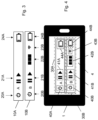
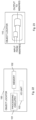
- Fig. 18 schematically illustrates this scenario where the part location representation 44 around the object part 24 is generated in step S1, i.e., during the object detection step, whereas the part location representation 44' is a so-called additional part location representation determined as previously described herein in connection with step S50. As shown in the upper part of Fig. 18 , there are therefore two part location representations 44, 44' positioned around this object part 24. However, when augmenting the picture with location representations or bounding boxes 30, 40, 41, 42, 43, 44 as shown in the lower part of Fig.
- Step S70 therefore removes any additional part location representation 44' determined in step S50 when there is already a part location representation 44 generated for the object part 24.
- step S70 in Fig. 14 comprises discarding an additional part location representation 44' overlapping with a part location representation 44 of a detected object part 24.
- step S70 the detected object part 24 having a generated part location representation 44 overlapping with the discarded additional part location representation 44' is removed from the list L part in step S71 to indicate that this object part 24 has already been processed and its part location representation is already present in the list L display where it was added in step S61.
- any remaining, i.e., non-discarded, additional part location representations 41 as determined in step S50 are then added to the list L display in step S72.
- Fig. 18 illustrates one such additional part location representation 41 for an object part 21 that was not detected in step S1.
- the addition of such additional part location representations 41 to the list L display means that also object parts 21 that were not detected, such as due to complete or partly occlusion when the picture was taken or the video was recorded, will be augmented by applying the homography to the geometric model.
- step S73 removes all detected object part or parts identified in step S4 from the list L part to indicate that they have already been processed and that their part location representations are already present in the list L display .
- the actual threshold value used in the comparison with the IoU can be determined in an optimization procedure. A value of the threshold value of 0.4 has proved to give good results.
- the picture may, thus, be augmented with perceptual information based on the location of the at least one object and the object parts in the picture.
- the augmented picture may then be output for display on a screen of the user device.
- the picture can be augmented with perceptual information based on the locations of the objects and object parts.
- the type of perceptual information to augment the picture can be selected based on the classes of the objects and object parts.
- Perceptual information as used herein relates to any information or data that could be used to augment a scene.
- Non-limiting, but illustrative, examples of such perceptual information includes name of a detected building, name of a detected person, etc.
- Examples of perceptual information could be bounding boxes 30, 40, 41, 42, 43 around the objects 10 and object parts 20, 21, 22, 23 as shown in Fig. 5 .
- the visualized bounding boxes 30, 40, 41, 42, 43 may optionally be complemented with information or identifiers of the objects 10 and object parts 20, 21, 22, 23 enclosed by the bounding boxes 30,40,41,42,43. This information or identifiers could, for instance, identify the name or type of ports in the baseband switcher 10.
- ( x i , y i ), 1 ⁇ i ⁇ M represents a coordinate of a part location representation from the geometric model
- 1 ⁇ i ⁇ M represents a corresponding coordinate of a part location representation of an identified detected object part
- M represents the number of coordinates.
- the minimization of the error can be done using known methods.
- Illustrative, but non-limiting examples of such methods include direct linear transform (DLT) algorithm, non-linear least square minimization techniques, such as Levenberg-Marquardt algorithm, Gauss-Newton algorithm, and regression techniques, such as random sample consensus (RANSAC).
- DLT direct linear transform
- non-linear least square minimization techniques such as Levenberg-Marquardt algorithm, Gauss-Newton algorithm
- regression techniques such as random sample consensus (RANSAC).
- the object parts in the geometric model are used as the first or source picture and the object parts detected in the picture captured by the user device as the second or destination picture.
- four corresponding points are derived from each object part correspondence.
- the four corners of the part location representations or bounding boxes are regarded as corresponding points: x p y p ⁇ x d y d x p + w p , y p ⁇ x d
- the four corners are instead defined as: x 1 p , y 1 p ⁇ x 1 d , y 1 d x 2 p , y 1 p ⁇ x 2 d , y 1 d x 1 p , y 2 p ⁇ x 1 d , y 2 d x 2 p , y 2 p ⁇ x 2 d , y 2 d
- the object parts from the geometric model are matched with the detected object parts based on their class c. If an object part from the geometric model was not detected in step S1 of Fig. 6 , that object part is ignored in the estimation of the homography. If more than one object part (detected or from the geometric model) has the same class, all possible 1-1 mappings are tried for the these object parts. As an example, consider an object with object parts p 1 , p 2 , p 3 with corresponding classes c 1 , c 1 , c 2 . The detected object parts that we want to match are d 1 , d 2 , d 3 with classes c 1 , c 1 , c 2 .
- the method also comprises an initial verification whether the picture taken by the user device can be used in the object locating method. For instance, when a new picture is captured by the camera of the user device, one or more sensors in the user device can be used to verify that the user device was held horizontally with regard to the ground when the picture was captured. This initial verification ensures that objects appear in specific, known orientations. Hence, if the user device was slanted or rotated when the picture was taken as verified using the at least one sensor, then the picture is preferably ignored.
- different geometric models may be available for different angles or rotations of the object and the object parts.
- the particular geometric model to use for a current picture could be determined based on the orientation or rotation angle of the user device when capturing the picture as determined by the at least one sensor. For instance, a first geometric model is used if the rotation angle of the user device relative ground is ⁇ 10°, a second geometric model is used if the rotation angle is 10-45°, and so forth.
- N is the number of detected object parts with classes that appear in the geometric model
- ( w d i , h d i ) is the width and height of the bounding box of each detected object part d i
- the estimated size of the object is used as the size of the search window that is used to check if the object is present.
- ( x d i , y d i ) i.e., the top-left corner from the detected object parts d i , is used to generate possible search locations.
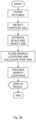
- Fig. 21 illustrates the processing taking place for each of the search locations.
- a first step comprises finding the object parts from L parts that are inside the search window at the current search location.
- a next step verifies that the object parts in the search window can form at least one minimal identifying group from the geometric model of the object, and that there are no extra object parts in the search window. If not, the object is not at this search location and the next search location can be considered. If the identified detected object parts form at least one minimal identifying group and if there are no extra object parts in the search window not forming part of the object, the homography H mapping the object parts in the geometric model to the detected object parts is estimated together with the associated error ⁇ . Then, if ⁇ ⁇ ⁇ max , the homography H is used to map the bounding boxes for the object and for any missing object parts into the picture coordinates.
- Fig. 20 This means that all the bounding boxes in L display are drawn on top of the original picture and displayed to the user.
- the filtering step, detecting step and displaying step in Fig. 20 are done once for each picture, while the other steps in Fig. 20 are preferably repeated for each object.
- an object locator comprising a processing circuitry and a memory comprising instructions executable by the processing circuitry.
- the processing circuitry is operative to apply at least one object detector to a picture to detect object parts in the picture and generate, for each detected object part, a part location representation defining a region of the picture.
- the processing circuitry is also operative to estimate a size of an object comprising object parts in the picture based on a geometric model of the object and of the object parts and based on the part location representations.
- the processing circuitry is further operative to determine, based on the part location representations, search locations in the picture for a search window having a size that is based on the estimated size of the object.
- Z is a positive number larger than one and ( w d i , h d i ) represents width and height of the region of the picture defined by a part location representation for a detected object part d i .
- the processing circuitry is operative to estimate the homography if the identified detected object part(s) form(s) at least a minimal identifying group defined by the geometrical model and constituting a distinctive group of object parts uniquely defining the object.
- the processing circuitry is operative to map, if the error is smaller than the threshold value and for the object, an object location representation from the geometric model into the object location representation defining a region of the picture based on the homography.
- the processing circuitry is operative to add the object location representation to L display .
- ( x i , y i ), 1 ⁇ i ⁇ M represents a coordinate of a part location representation from the geometric model
- 1 ⁇ i ⁇ M represents a corresponding coordinate of a part location representation of an identified detected object part
- M represents the number of coordinates.
- At least some of the steps, functions, procedures, modules and/or blocks described herein may be implemented in software such as a computer program for execution by suitable processing circuitry such as one or more processors or processing units.
- processing circuitry includes, but is not limited to, one or more microprocessors, one or more Digital Signal Processors (DSPs), one or more Central Processing Units (CPUs), video acceleration hardware, and/or any suitable programmable logic circuitry such as one or more Field Programmable Gate Arrays (FPGAs), or one or more Programmable Logic Controllers (PLCs).
- DSPs Digital Signal Processors
- CPUs Central Processing Units
- FPGAs Field Programmable Gate Arrays
- PLCs Programmable Logic Controllers
- Fig. 22 is a schematic block diagram illustrating an example of an object locator 100 according to an embodiment.
- the object locator 100 comprises a processing circuitry 101, such as a processor, and a memory 102.
- the memory 102 comprises instructions executable by the processing circuitry 101.
- Fig. 23 is a schematic block diagram illustrating an object locator 110 based on a hardware circuitry implementation according to an embodiment.
- suitable hardware circuitry include one or more suitably configured or possibly reconfigurable electronic circuitry, e.g., Application Specific Integrated Circuits (ASICs), Field Programmable Gate Arrays (FPGAs), or any other hardware logic such as circuits based on discrete logic gates and/or flip-flops interconnected to perform specialized functions in connection with suitable registers (REG), and/or memory units (MEM).
- ASICs Application Specific Integrated Circuits
- FPGAs Field Programmable Gate Arrays
- REG registers
- MEM memory units
- the processing circuitry 210 is thus configured to perform, when executing the computer program 240, well-defined processing tasks such as those described herein.
- the software or computer program 240 stored on a computer-readable storage medium, such as the memory 220, in particular a non-volatile medium.
- the computer-readable medium may include one or more removable or non-removable memory devices including, but not limited to a Read-Only Memory (ROM), a Random Access Memory (RAM), a Compact Disc (CD), a Digital Versatile Disc (DVD), a Blu-ray disc, a Universal Serial Bus (USB) memory, a Hard Disk Drive (HDD) storage device, a flash memory, a magnetic tape, or any other conventional memory device.
- the computer program 240 may, thus, be loaded into the operating memory 220 for execution by the processing circuitry 210.
- a special-purpose network device may include hardware comprising processing or computing resource(s), which typically include a set of one or more processors, and physical network interfaces (Nls), which sometimes are called physical ports, as well as non-transitory machine readable storage media having stored thereon software.
- a physical NI may be seen as hardware in a network device through which a network connection is made, e.g. wirelessly through a wireless network interface controller (WNIC) or through plugging in a cable to a physical port connected to a network interface controller (NIC).
- WNIC wireless network interface controller
- NIC network interface controller
- the software can be executed by the hardware to instantiate a set of one or more software instance(s).
- Each of the software instance(s), and that part of the hardware that executes that software instance may form a separate virtual network element.
- network device may refer to any device located in connection with a communication network, including but not limited to devices in access networks, core networks and similar network structures.
- the term network device may also encompass cloud-based network devices.
Landscapes
- Engineering & Computer Science (AREA)
- Theoretical Computer Science (AREA)
- Physics & Mathematics (AREA)
- General Physics & Mathematics (AREA)
- Multimedia (AREA)
- Computer Vision & Pattern Recognition (AREA)
- Quality & Reliability (AREA)
- Computing Systems (AREA)
- Artificial Intelligence (AREA)
- Databases & Information Systems (AREA)
- Evolutionary Computation (AREA)
- General Health & Medical Sciences (AREA)
- Medical Informatics (AREA)
- Software Systems (AREA)
- Health & Medical Sciences (AREA)
- Image Analysis (AREA)
Claims (15)
- Objektstandortbestimmungsverfahren, umfassend:Anwenden (S1) mindestens eines teilbasierten Objektdetektors (3) auf ein Bild, um in dem Bild Objektteile (20, 21, 22, 23, 24) zu detektieren und für jeden detektierten Objektteil (20, 21, 22, 23, 24) eine Teilstandortdarstellung (40, 41, 42, 43, 44) zu erzeugen, die einen Bereich des Bildes definiert, wobei die Teilstandortdarstellung (40, 41, 42, 43, 44) ein Begrenzungsrahmen eines jeweiligen detektierten Objektteils (20, 21, 22, 23, 24) ist;Schätzen (S2) einer Größe eines Objekts (10), das Objektteile (20, 21, 22, 23, 24) in dem Bild umfasst, basierend auf einem geometrischen Modell des Objekts (10) und der Objektteile (20, 21, 22, 23, 24) und basierend auf den Teilstandortdarstellungen (40, 41, 42, 43, 44), wobei das geometrische Modell eine Geometrie des Objekts (10) und seiner enthaltenen Objektteile (20, 21, 22, 23, 24) definiert, wobei das geometrische Modell ferner eine Standardgröße des Objekts (10) definiert und wobei die Teilstandortdarstellungen zusammen mit passenden Teilstandortdarstellungen aus dem geometrischen Modell dazu verwendet werden, die Größe des Objekts (10) zu schätzen, wobei das Schätzen (S2) der Größe des Objekts (10) ferner Folgendes umfasst:Berechnen eines Skalierungsfaktors basierend auf den Teilstandortdarstellungen (40, 41, 42, 43, 44); undBestimmen der Größe des Objekts (10) basierend auf dem Skalierungsfaktor und der Standardgröße des Objekts (10), die durch das geometrische Modell definiert ist;wobei der Skalierungsfaktor als eine Funktion einer Quadratwurzel eines Quotienten aus einem Gebiet eines Bereichs des Bildes, der durch eine Teilstandortdarstellung (40, 41, 42, 43, 44) für einen detektierten Objektteil (20, 21, 22, 23, 24) definiert ist, und einem Gebiet eines Bereichs, der durch eine Teilstandortdarstellung für einen Objektteil aus dem geometrischen Modell definiert ist, berechnet wird, wobei der Objektteil aus dem geometrischen Modell ein entsprechender oder zugeordneter Objektteil in Bezug auf den detektierten Objektteil ist;Bestimmen (S3), basierend auf den Teilstandortdarstellungen (40, 41, 42, 43, 44), von Suchstandorten (51) in dem Bild für ein Suchfenster (52), das eine Größe aufweist, die mindestens die geschätzte Größe des Objekts (10) beträgt; undfür mindestens einen Abschnitt der bestimmten Suchstandorte (51) :Identifizieren (S4) eines etwaigen detektierten Objektteils (20, 21, 22, 23) innerhalb des Suchfensters (52), das an dem bestimmten Suchstandort (51) positioniert ist;Schätzen (S5) einer Homographie, die einen Objektteil oder Objektteile in dem geometrischen Modell dem/den identifizierten detektierten Objektteil(en) (20, 21, 22, 23) durch Minimieren eines Fehlers zwischen dem/den zugeordneten Objektteil(en) und dem/den identifizierten detektierten Objektteil(en) (20,21, 22, 23) zuordnet; undBestimmen (S7), wenn der Fehler geringer als ein Schwellenwert ist und für das Objekt (10), einer Objektstandortdarstellung (30), die einen Bereich des Bildes basierend auf der Homographie und dem geometrischen Modell definiert, wobei die Objektstandortdarstellung (30) ein Begrenzungsrahmen des Objekts (10) ist.
- Objektstandortbestimmer (100, 120), umfassend:eine Verarbeitungsschaltung (101, 121); undeinen Speicher (102, 122), umfassend Anweisungen, die durch die Verarbeitungsschaltung (101, 121) ausführbar sind, wobei die Verarbeitungsschaltung (101, 121) zu Folgendem dient:Anwenden mindestens eines teilbasierten Objektdetektors (3) auf ein Bild, um in dem Bild Objektteile (20, 21, 22, 23, 24) zu detektieren und für jeden detektierten Objektteil (20, 21, 22, 23, 24) eine Teilstandortdarstellung (40, 41, 42, 43, 44) zu erzeugen, die einen Bereich des Bildes definiert, wobei die Teilstandortdarstellung (40, 41, 42, 43, 44) ein Begrenzungsrahmen eines jeweiligen detektierten Objektteils (20, 21, 22, 23, 24) ist;Schätzen einer Größe eines Objekts (10), das Objektteile (20, 21, 22, 23, 24) in dem Bild umfasst, basierend auf einem geometrischen Modell des Objekts (10) und der Objektteile (20, 21, 22, 23, 24) und basierend auf den Teilstandortdarstellungen (40, 41, 42, 43, 44), wobei das geometrische Modell eine Geometrie des Objekts (10) und seiner enthaltenen Objektteile (20, 21, 22, 23, 24) definiert, und wobei die Teilstandortdarstellungen zusammen mit passenden Teilstandortdarstellungen aus dem geometrischen Modell dazu verwendet werden, die Größe des Objekts (10) zu schätzen, wobei die Verarbeitungsschaltung (101, 121) ferner zu Folgendem dient:Berechnen eines Skalierungsfaktors basierend auf den Teilstandortdarstellungen (40, 41, 42, 43, 44), wobei der Skalierungsfaktor als eine Funktion einer Quadratwurzel eines Quotienten aus einem Gebiet eines Bereichs des Bildes, der durch eine Teilstandortdarstellung (40, 41, 42, 43, 44) für einen detektierten Objektteil (20, 21, 22, 23, 24) definiert ist, und einem Gebiet eines Bereichs, der durch eine Teilstandortdarstellung für einen Objektteil aus dem geometrischen Modell definiert ist, berechnet wird, wobei der Objektteil aus dem geometrischen Modell ein entsprechender oder zugeordneter Objektteil in Bezug auf den detektierten Objektteil ist, undBestimmen der Größe des Objekts (10) basierend auf dem Skalierungsfaktor und einer Standardgröße des Objekts (10), die durch das geometrische Modell definiert ist;Bestimmen, basierend auf den Teilstandortdarstellungen (40, 41, 42, 43, 44), von Suchstandorten (51) in dem Bild für ein Suchfenster (52), das eine Größe aufweist, die mindestens die geschätzte Größe des Objekts (10) beträgt; undfür mindestens einen Abschnitt der bestimmten Suchstandorte (51) :Identifizieren eines etwaigen Objektteils (20, 21, 22, 23) innerhalb des Suchfensters (52), das an dem bestimmten Suchstandort (51) positioniert ist;Schätzen einer Homographie, die einen Objektteil oder Objektteile in dem geometrischen Modell dem/den identifizierten detektierten Objektteil(en) (20, 21, 22, 23) durch Minimieren eines Fehlers zwischen dem/den zugeordneten Objektteil(en) und dem/den identifizierten detektierten Objektteil(en) (20,21, 22, 23) zuordnet; undBestimmen, wenn der Fehler geringer als ein Schwellenwert ist und für das Objekt (10), einer Objektstandortdarstellung (30), die einen Bereich des Bildes basierend auf der Homographie und dem geometrischen Modell definiert, wobei die Objektstandortdarstellung (30) ein Begrenzungsrahmen des Objekts (10) ist.
- Objektstandortbestimmer nach Anspruch 2, wobei die Verarbeitungsschaltung (101, 121) dazu dient, den Skalierungsfaktor

i , hdi ) Breite und Höhe des Bereichs des Bildes darstellt, der durch eine Teilstandortdarstellung (40, 42, 43, 44) für einen detektierten Objektteil di (20, 22, 23, 24) definiert ist, (wpi, hpi ) Breite und Höhe eines Bereichs darstellt, der durch eine Teilstandortdarstellung für einen Objektteil pi aus dem geometrischen Modell definiert ist, f ( ) eine Funktion ist, i = 1 ... N und N die Anzahl detektierter Objektteile (20, 22, 23, 24) darstellt. - Objektstandortbestimmer nach einem der Ansprüche 2 bis 3, wobei die Verarbeitungsschaltung (101, 121) dazu dient, ein Raster {xd
i , ydj } (50) von Suchstandorten (51) in dem Bild zu bestimmen, wobei (xdi , ydi ) eine Koordinate des Bereichs des Bildes darstellt, die durch eine Teilstandortdarstellung (40, 42, 43, 44) für einen detektierten Objektteil di (20, 22, 23, 24) definiert ist, 1 ≤ i, j ≤ N und N die Anzahl detektierter Objektteile (20, 22, 23, 24) darstellt. - Objektstandortbestimmer nach Anspruch 4, wobei die Verarbeitungsschaltung (101, 121) zu Folgendem dient:Bestimmen einer minimalen Schrittgröße xSchritt in einer x-Richtung und einer minimalen Schrittgröße ySchritt in einer y-Richtung basierend auf den Teilstandortdarstellungen (40, 42, 43, 44); undIdentifizieren eines etwaigen detektierten Objektteils und Schätzen einer Homographie für Suchstandorte (51) des Rasters (50), die einen Abstand in der x-Richtung zu einem benachbarten Suchstandort in dem Raster (50) aufweisen, der gleich oder größer xSchritt ist, und einen Abstand in der y-Richtung zu einem benachbarten Suchstandort in dem Raster (50) aufweisen, der gleich oder größer ySchritt ist.
- Objektstandortbestimmer nach Anspruch 5, wobei die Verarbeitungsschaltung (101, 121) zu Folgendem dient:Berechnen von
 Berechnen von
i , hdi ) Breite und Höhe des Bereichs des Bildes darstellt, der durch eine Teilstandortdarstellung (40, 42, 43, 44) für einen detektierten Objektteil di (20, 22, 23, 24) definiert ist. - Objektstandortbestimmer nach einem der Ansprüche 2 bis 6, wobei die Verarbeitungsschaltung (101, 121) dazu dient, die Homographie zu schätzen, wenn der/die identifizierte(n) detektierte(n) Objektteil(e) (20, 22, 23) mindestens eine minimale identifizierende Gruppe bildet/bilden, die durch das geometrische Modell definiert ist und eine distinktive Gruppe von Objektteilen ausmacht, die das Objekt (10) eindeutig definiert.
- Objektstandortbestimmer nach einem der Ansprüche 2 bis 7, wobei die Verarbeitungsschaltung (101, 121) dazu dient, für den mindestens einen Abschnitt der bestimmten Suchstandorte (51) und wenn der Fehler geringer als der Schwellenwert ist, eine zusätzliche Teilstandortdarstellung (41) zu bestimmen, die einen Bereich des Bildes für einen etwaigen Objektteil (21) des Objekts (10) definiert, der unter den Teilstandortdarstellungen (40, 42, 43, 44) der detektierten Objektteile (20, 22, 23, 24) nicht vorhanden ist, basierend auf der Homographie und dem geometrischen Modell, wobei der nichtdetektierte Objektteil (21) in dem geometrischen Modell enthalten ist und das geometrische Modell zusammen mit der Homographie dazu verwendet wird, den nichtdetektierten Objektteil (21) aus dem geometrischen Modell zuzuordnen, um die zusätzliche Teilstandortdarstellung (41) zu bestimmen.
- Objektstandortbestimmer nach einem der Ansprüche 2 bis 8, wobei die Verarbeitungsschaltung (101, 121) zu Folgendem dient:Erstellen einer Liste LTeil der detektierten Objektteile;Erstellen einer Liste LAnzeige anzuzeigender Standortdarstellungen, wobei LAnzeige Teilstandortdarstellungen (40, 42, 43, 44) der detektierten Objektteile (20, 22, 23, 24) umfasst; undIdentifizieren eines etwaigen detektierten Objektteils (20, 22, 23) aus LTeil innerhalb des Suchfensters (52), das an dem bestimmten Suchstandort (51) positioniert ist.
- Objektstandortbestimmer nach Anspruch 8 und 9, wobei die Verarbeitungsschaltung (101, 121), für den mindestens einen Abschnitt der bestimmten Suchstandorte (51) und wenn der Fehler geringer als der Schwellenwert ist, zu Folgendem dient:Verwerfen einer zusätzlichen Teilstandortdarstellung (44'), die mit einer Teilstandortdarstellung (44) eines detektierten Objektteils (24) außerhalb des Suchfensters (52), das an dem bestimmten Suchstandort (51) positioniert ist, überlappt;Entfernen, aus LTeil , des detektierten Objektteils (24), der eine Teilstandortdarstellung (44) aufweist, die mit der verworfenen zusätzlichen Teilstandortdarstellung (44') überlappt;Hinzufügen nichtverworfener Teilstandortdarstellungen (41) zu LAnzeige ; undEntfernen, aus LTeil , des/der identifizierten detektierten Objektteils/Objektteile (20, 22, 23).
- Objektstandortbestimmer nach Anspruch 10, wobei die Verarbeitungsschaltung (101, 121), für den mindestens einen Abschnitt der bestimmten Suchstandorte (51) und wenn der Fehler geringer als der Schwellenwert ist, zu Folgendem dient:Berechnen einer Intersection-over-Union, IoU, für eine zusätzliche Teilstandortdarstellung (44') und eine Teilstandortdarstellung (44) eines detektierten Objektteils (24) außerhalb des Suchfensters (52), das an dem bestimmten Suchstandort (51) positioniert ist; undBestimmen, dass die zusätzliche Teilstandortdarstellung (44') mit der Teilstandortdarstellung (44) des detektierten Objektteils (24) überlappt, wenn die IoU einen Schwellenwert überschreitet.
- Objektstandortbestimmer nach einem der Ansprüche 2 bis 11, wobei die Verarbeitungsschaltung (101, 121) dazu dient,die Homographie
 des Quadratfehlers
- Objektstandortbestimmer nach einem der Ansprüche 2 bis 12, wobei das Objekt (10) und die Objektteile (20, 21 ,22, 23, 24), die darin umfasst sind, starr sind.
- Benutzervorrichtung (1), umfassend einen Objektstandortbestimmer (100) nach einem der Ansprüche 2 bis 13.
- Netzknoten (60, 300), umfassend einen Objektstandortbestimmer (100) nach einem der Ansprüche 2 bis 13.
Applications Claiming Priority (1)
| Application Number | Priority Date | Filing Date | Title |
|---|---|---|---|
| PCT/EP2019/054349 WO2020169199A1 (en) | 2019-02-21 | 2019-02-21 | Object location determination |
Publications (3)
| Publication Number | Publication Date |
|---|---|
| EP3928246A1 EP3928246A1 (de) | 2021-12-29 |
| EP3928246C0 EP3928246C0 (de) | 2024-07-10 |
| EP3928246B1 true EP3928246B1 (de) | 2024-07-10 |
Family
ID=65685298
Family Applications (1)
| Application Number | Title | Priority Date | Filing Date |
|---|---|---|---|
| EP19708969.1A Active EP3928246B1 (de) | 2019-02-21 | 2019-02-21 | Objektstandortbestimmung |
Country Status (3)
| Country | Link |
|---|---|
| US (1) | US12190574B2 (de) |
| EP (1) | EP3928246B1 (de) |
| WO (1) | WO2020169199A1 (de) |
Citations (1)
| Publication number | Priority date | Publication date | Assignee | Title |
|---|---|---|---|---|
| US20170330059A1 (en) * | 2016-05-11 | 2017-11-16 | Xerox Corporation | Joint object and object part detection using web supervision |
Family Cites Families (5)
| Publication number | Priority date | Publication date | Assignee | Title |
|---|---|---|---|---|
| US9275302B1 (en) * | 2012-08-24 | 2016-03-01 | Amazon Technologies, Inc. | Object detection and identification |
| US10115199B2 (en) * | 2014-10-08 | 2018-10-30 | Decision Sciences International Corporation | Image based object locator |
| JP6528723B2 (ja) * | 2016-05-25 | 2019-06-12 | トヨタ自動車株式会社 | 物体認識装置、物体認識方法及びプログラム |
| FR3055446A1 (fr) | 2016-09-01 | 2018-03-02 | Arjo Solutions | Procede et syteme de generation de la signature d'une surface |
| US10438362B2 (en) * | 2017-05-31 | 2019-10-08 | Here Global B.V. | Method and apparatus for homography estimation |
-
2019
- 2019-02-21 US US17/428,863 patent/US12190574B2/en active Active
- 2019-02-21 WO PCT/EP2019/054349 patent/WO2020169199A1/en not_active Ceased
- 2019-02-21 EP EP19708969.1A patent/EP3928246B1/de active Active
Patent Citations (1)
| Publication number | Priority date | Publication date | Assignee | Title |
|---|---|---|---|---|
| US20170330059A1 (en) * | 2016-05-11 | 2017-11-16 | Xerox Corporation | Joint object and object part detection using web supervision |
Also Published As
| Publication number | Publication date |
|---|---|
| WO2020169199A1 (en) | 2020-08-27 |
| US20220157039A1 (en) | 2022-05-19 |
| EP3928246C0 (de) | 2024-07-10 |
| US12190574B2 (en) | 2025-01-07 |
| EP3928246A1 (de) | 2021-12-29 |
Similar Documents
| Publication | Publication Date | Title |
|---|---|---|
| CN109242913B (zh) | 采集器相对参数的标定方法、装置、设备和介质 | |
| US10373380B2 (en) | 3-dimensional scene analysis for augmented reality operations | |
| US20200364454A1 (en) | Three dimensional bounding box estimation from two dimensional images | |
| US10482681B2 (en) | Recognition-based object segmentation of a 3-dimensional image | |
| US11051000B2 (en) | Method for calibrating cameras with non-overlapping views | |
| CN107633526B (zh) | 一种图像跟踪点获取方法及设备、存储介质 | |
| WO2019099095A1 (en) | Pose estimation and model retrieval for objects in images | |
| US20210042996A1 (en) | System and method for integrating objects in monocular slam | |
| JP2018507476A (ja) | コンピュータビジョンに関する遮蔽処理 | |
| CN113763466B (zh) | 一种回环检测方法、装置、电子设备和存储介质 | |
| JP2014530391A (ja) | ローカライズされ、セグメンテーションされた画像のネットワークキャプチャ及び3dディスプレイ | |
| US20170206430A1 (en) | Method and system for object detection | |
| CN107749069B (zh) | 图像处理方法、电子设备和图像处理系统 | |
| CN113112542A (zh) | 一种视觉定位方法、装置、电子设备及存储介质 | |
| US11361548B2 (en) | Method and system for multi instance visual tracking based on observer motion modelling | |
| CN110673607A (zh) | 动态场景下的特征点提取方法、装置、及终端设备 | |
| CN111753858A (zh) | 一种点云匹配方法、装置和重定位系统 | |
| US12067771B2 (en) | Object location determination in frames of a video stream | |
| US20240066723A1 (en) | Automatic bin detection for robotic applications | |
| US11227166B2 (en) | Method and device for evaluating images, operating assistance method, and operating device | |
| JP2014102805A (ja) | 情報処理装置、情報処理方法及びプログラム | |
| CN113793349B (zh) | 目标检测方法及装置、计算机可读存储介质、电子设备 | |
| US12190574B2 (en) | Object location determination | |
| CN116681884B (zh) | 一种对象检测方法和相关装置 | |
| Schaeferling et al. | Object recognition and pose estimation on embedded hardware: SURF‐based system designs accelerated by FPGA logic |
Legal Events
| Date | Code | Title | Description |
|---|---|---|---|
| STAA | Information on the status of an ep patent application or granted ep patent |
Free format text: STATUS: UNKNOWN |
|
| STAA | Information on the status of an ep patent application or granted ep patent |
Free format text: STATUS: THE INTERNATIONAL PUBLICATION HAS BEEN MADE |
|
| PUAI | Public reference made under article 153(3) epc to a published international application that has entered the european phase |
Free format text: ORIGINAL CODE: 0009012 |
|
| STAA | Information on the status of an ep patent application or granted ep patent |
Free format text: STATUS: REQUEST FOR EXAMINATION WAS MADE |
|
| 17P | Request for examination filed |
Effective date: 20210809 |
|
| AK | Designated contracting states |
Kind code of ref document: A1 Designated state(s): AL AT BE BG CH CY CZ DE DK EE ES FI FR GB GR HR HU IE IS IT LI LT LU LV MC MK MT NL NO PL PT RO RS SE SI SK SM TR |
|
| DAV | Request for validation of the european patent (deleted) | ||
| DAX | Request for extension of the european patent (deleted) | ||
| STAA | Information on the status of an ep patent application or granted ep patent |
Free format text: STATUS: EXAMINATION IS IN PROGRESS |
|
| 17Q | First examination report despatched |
Effective date: 20230927 |
|
| REG | Reference to a national code |
Ref country code: DE Ref country code: DE Ref legal event code: R079 Ref document number: 602019054933 Country of ref document: DE Free format text: PREVIOUS MAIN CLASS: G06K0009000000 Ipc: G06V0010440000 |
|
| GRAP | Despatch of communication of intention to grant a patent |
Free format text: ORIGINAL CODE: EPIDOSNIGR1 |
|
| STAA | Information on the status of an ep patent application or granted ep patent |
Free format text: STATUS: GRANT OF PATENT IS INTENDED |
|
| RIC1 | Information provided on ipc code assigned before grant |
Ipc: G06V 20/20 20220101ALI20240327BHEP Ipc: G06V 10/10 20220101ALI20240327BHEP Ipc: G06F 18/213 20230101ALI20240327BHEP Ipc: G06V 10/77 20220101ALI20240327BHEP Ipc: G06V 10/52 20220101ALI20240327BHEP Ipc: G06V 10/44 20220101AFI20240327BHEP |
|
| INTG | Intention to grant announced |
Effective date: 20240415 |
|
| GRAS | Grant fee paid |
Free format text: ORIGINAL CODE: EPIDOSNIGR3 |
|
| GRAA | (expected) grant |
Free format text: ORIGINAL CODE: 0009210 |
|
| STAA | Information on the status of an ep patent application or granted ep patent |
Free format text: STATUS: THE PATENT HAS BEEN GRANTED |
|
| AK | Designated contracting states |
Kind code of ref document: B1 Designated state(s): AL AT BE BG CH CY CZ DE DK EE ES FI FR GB GR HR HU IE IS IT LI LT LU LV MC MK MT NL NO PL PT RO RS SE SI SK SM TR |
|
| REG | Reference to a national code |
Ref country code: CH Ref legal event code: EP |
|
| REG | Reference to a national code |
Ref country code: DE Ref legal event code: R096 Ref document number: 602019054933 Country of ref document: DE |
|
| U01 | Request for unitary effect filed |
Effective date: 20240718 |
|
| U07 | Unitary effect registered |
Designated state(s): AT BE BG DE DK EE FI FR IT LT LU LV MT NL PT RO SE SI Effective date: 20240902 |
|
| PG25 | Lapsed in a contracting state [announced via postgrant information from national office to epo] |
Ref country code: NO Free format text: LAPSE BECAUSE OF FAILURE TO SUBMIT A TRANSLATION OF THE DESCRIPTION OR TO PAY THE FEE WITHIN THE PRESCRIBED TIME-LIMIT Effective date: 20241010 |
|
| PG25 | Lapsed in a contracting state [announced via postgrant information from national office to epo] |
Ref country code: GR Free format text: LAPSE BECAUSE OF FAILURE TO SUBMIT A TRANSLATION OF THE DESCRIPTION OR TO PAY THE FEE WITHIN THE PRESCRIBED TIME-LIMIT Effective date: 20241011 Ref country code: PL Free format text: LAPSE BECAUSE OF FAILURE TO SUBMIT A TRANSLATION OF THE DESCRIPTION OR TO PAY THE FEE WITHIN THE PRESCRIBED TIME-LIMIT Effective date: 20240710 |
|
| PG25 | Lapsed in a contracting state [announced via postgrant information from national office to epo] |
Ref country code: IS Free format text: LAPSE BECAUSE OF FAILURE TO SUBMIT A TRANSLATION OF THE DESCRIPTION OR TO PAY THE FEE WITHIN THE PRESCRIBED TIME-LIMIT Effective date: 20241110 |
|
| PG25 | Lapsed in a contracting state [announced via postgrant information from national office to epo] |
Ref country code: HR Free format text: LAPSE BECAUSE OF FAILURE TO SUBMIT A TRANSLATION OF THE DESCRIPTION OR TO PAY THE FEE WITHIN THE PRESCRIBED TIME-LIMIT Effective date: 20240710 |
|
| PG25 | Lapsed in a contracting state [announced via postgrant information from national office to epo] |
Ref country code: ES Free format text: LAPSE BECAUSE OF FAILURE TO SUBMIT A TRANSLATION OF THE DESCRIPTION OR TO PAY THE FEE WITHIN THE PRESCRIBED TIME-LIMIT Effective date: 20240710 Ref country code: RS Free format text: LAPSE BECAUSE OF FAILURE TO SUBMIT A TRANSLATION OF THE DESCRIPTION OR TO PAY THE FEE WITHIN THE PRESCRIBED TIME-LIMIT Effective date: 20241010 |
|
| PG25 | Lapsed in a contracting state [announced via postgrant information from national office to epo] |
Ref country code: RS Free format text: LAPSE BECAUSE OF FAILURE TO SUBMIT A TRANSLATION OF THE DESCRIPTION OR TO PAY THE FEE WITHIN THE PRESCRIBED TIME-LIMIT Effective date: 20241010 Ref country code: PL Free format text: LAPSE BECAUSE OF FAILURE TO SUBMIT A TRANSLATION OF THE DESCRIPTION OR TO PAY THE FEE WITHIN THE PRESCRIBED TIME-LIMIT Effective date: 20240710 Ref country code: NO Free format text: LAPSE BECAUSE OF FAILURE TO SUBMIT A TRANSLATION OF THE DESCRIPTION OR TO PAY THE FEE WITHIN THE PRESCRIBED TIME-LIMIT Effective date: 20241010 Ref country code: IS Free format text: LAPSE BECAUSE OF FAILURE TO SUBMIT A TRANSLATION OF THE DESCRIPTION OR TO PAY THE FEE WITHIN THE PRESCRIBED TIME-LIMIT Effective date: 20241110 Ref country code: HR Free format text: LAPSE BECAUSE OF FAILURE TO SUBMIT A TRANSLATION OF THE DESCRIPTION OR TO PAY THE FEE WITHIN THE PRESCRIBED TIME-LIMIT Effective date: 20240710 Ref country code: GR Free format text: LAPSE BECAUSE OF FAILURE TO SUBMIT A TRANSLATION OF THE DESCRIPTION OR TO PAY THE FEE WITHIN THE PRESCRIBED TIME-LIMIT Effective date: 20241011 Ref country code: ES Free format text: LAPSE BECAUSE OF FAILURE TO SUBMIT A TRANSLATION OF THE DESCRIPTION OR TO PAY THE FEE WITHIN THE PRESCRIBED TIME-LIMIT Effective date: 20240710 |
|
| U20 | Renewal fee for the european patent with unitary effect paid |
Year of fee payment: 7 Effective date: 20250227 |
|
| PG25 | Lapsed in a contracting state [announced via postgrant information from national office to epo] |
Ref country code: SM Free format text: LAPSE BECAUSE OF FAILURE TO SUBMIT A TRANSLATION OF THE DESCRIPTION OR TO PAY THE FEE WITHIN THE PRESCRIBED TIME-LIMIT Effective date: 20240710 |
|
| PG25 | Lapsed in a contracting state [announced via postgrant information from national office to epo] |
Ref country code: CZ Free format text: LAPSE BECAUSE OF FAILURE TO SUBMIT A TRANSLATION OF THE DESCRIPTION OR TO PAY THE FEE WITHIN THE PRESCRIBED TIME-LIMIT Effective date: 20240710 |
|
| PG25 | Lapsed in a contracting state [announced via postgrant information from national office to epo] |
Ref country code: SK Free format text: LAPSE BECAUSE OF FAILURE TO SUBMIT A TRANSLATION OF THE DESCRIPTION OR TO PAY THE FEE WITHIN THE PRESCRIBED TIME-LIMIT Effective date: 20240710 |
|
| PLBE | No opposition filed within time limit |
Free format text: ORIGINAL CODE: 0009261 |
|
| STAA | Information on the status of an ep patent application or granted ep patent |
Free format text: STATUS: NO OPPOSITION FILED WITHIN TIME LIMIT |
|
| 26N | No opposition filed |
Effective date: 20250411 |
|
| PG25 | Lapsed in a contracting state [announced via postgrant information from national office to epo] |
Ref country code: MC Free format text: LAPSE BECAUSE OF FAILURE TO SUBMIT A TRANSLATION OF THE DESCRIPTION OR TO PAY THE FEE WITHIN THE PRESCRIBED TIME-LIMIT Effective date: 20240710 |
|
| REG | Reference to a national code |
Ref country code: CH Ref legal event code: PL |
|
| PG25 | Lapsed in a contracting state [announced via postgrant information from national office to epo] |
Ref country code: CH Free format text: LAPSE BECAUSE OF NON-PAYMENT OF DUE FEES Effective date: 20250228 |
|
| PG25 | Lapsed in a contracting state [announced via postgrant information from national office to epo] |
Ref country code: IE Free format text: LAPSE BECAUSE OF NON-PAYMENT OF DUE FEES Effective date: 20250221 |
|
| U20 | Renewal fee for the european patent with unitary effect paid |
Year of fee payment: 8 Effective date: 20260227 |
|
| PGFP | Annual fee paid to national office [announced via postgrant information from national office to epo] |
Ref country code: GB Payment date: 20260227 Year of fee payment: 8 |