EP3928153B1 - Boitier de montage pour dispositif d'affichage et ensemble afficheur comportant un tel boitier - Google Patents
Boitier de montage pour dispositif d'affichage et ensemble afficheur comportant un tel boitier Download PDFInfo
- Publication number
- EP3928153B1 EP3928153B1 EP20703992.6A EP20703992A EP3928153B1 EP 3928153 B1 EP3928153 B1 EP 3928153B1 EP 20703992 A EP20703992 A EP 20703992A EP 3928153 B1 EP3928153 B1 EP 3928153B1
- Authority
- EP
- European Patent Office
- Prior art keywords
- rim
- mounting housing
- mounting
- housing
- thickness
- Prior art date
- Legal status (The legal status is an assumption and is not a legal conclusion. Google has not performed a legal analysis and makes no representation as to the accuracy of the status listed.)
- Active
Links
Images


Classifications
-
- G—PHYSICS
- G02—OPTICS
- G02F—OPTICAL DEVICES OR ARRANGEMENTS FOR THE CONTROL OF LIGHT BY MODIFICATION OF THE OPTICAL PROPERTIES OF THE MEDIA OF THE ELEMENTS INVOLVED THEREIN; NON-LINEAR OPTICS; FREQUENCY-CHANGING OF LIGHT; OPTICAL LOGIC ELEMENTS; OPTICAL ANALOGUE/DIGITAL CONVERTERS
- G02F1/00—Devices or arrangements for the control of the intensity, colour, phase, polarisation or direction of light arriving from an independent light source, e.g. switching, gating or modulating; Non-linear optics
- G02F1/01—Devices or arrangements for the control of the intensity, colour, phase, polarisation or direction of light arriving from an independent light source, e.g. switching, gating or modulating; Non-linear optics for the control of the intensity, phase, polarisation or colour
- G02F1/13—Devices or arrangements for the control of the intensity, colour, phase, polarisation or direction of light arriving from an independent light source, e.g. switching, gating or modulating; Non-linear optics for the control of the intensity, phase, polarisation or colour based on liquid crystals, e.g. single liquid crystal display cells
- G02F1/133—Constructional arrangements; Operation of liquid crystal cells; Circuit arrangements
- G02F1/1333—Constructional arrangements; Manufacturing methods
- G02F1/133308—Support structures for LCD panels, e.g. frames or bezels
-
- B—PERFORMING OPERATIONS; TRANSPORTING
- B60—VEHICLES IN GENERAL
- B60R—VEHICLES, VEHICLE FITTINGS, OR VEHICLE PARTS, NOT OTHERWISE PROVIDED FOR
- B60R11/00—Arrangements for holding or mounting articles, not otherwise provided for
- B60R11/02—Arrangements for holding or mounting articles, not otherwise provided for for radio sets, television sets, telephones, or the like; Arrangement of controls thereof
- B60R11/0229—Arrangements for holding or mounting articles, not otherwise provided for for radio sets, television sets, telephones, or the like; Arrangement of controls thereof for displays, e.g. cathodic tubes
- B60R11/0235—Arrangements for holding or mounting articles, not otherwise provided for for radio sets, television sets, telephones, or the like; Arrangement of controls thereof for displays, e.g. cathodic tubes of flat type, e.g. LCD
-
- G—PHYSICS
- G02—OPTICS
- G02F—OPTICAL DEVICES OR ARRANGEMENTS FOR THE CONTROL OF LIGHT BY MODIFICATION OF THE OPTICAL PROPERTIES OF THE MEDIA OF THE ELEMENTS INVOLVED THEREIN; NON-LINEAR OPTICS; FREQUENCY-CHANGING OF LIGHT; OPTICAL LOGIC ELEMENTS; OPTICAL ANALOGUE/DIGITAL CONVERTERS
- G02F1/00—Devices or arrangements for the control of the intensity, colour, phase, polarisation or direction of light arriving from an independent light source, e.g. switching, gating or modulating; Non-linear optics
- G02F1/01—Devices or arrangements for the control of the intensity, colour, phase, polarisation or direction of light arriving from an independent light source, e.g. switching, gating or modulating; Non-linear optics for the control of the intensity, phase, polarisation or colour
- G02F1/13—Devices or arrangements for the control of the intensity, colour, phase, polarisation or direction of light arriving from an independent light source, e.g. switching, gating or modulating; Non-linear optics for the control of the intensity, phase, polarisation or colour based on liquid crystals, e.g. single liquid crystal display cells
- G02F1/133—Constructional arrangements; Operation of liquid crystal cells; Circuit arrangements
- G02F1/1333—Constructional arrangements; Manufacturing methods
- G02F1/133308—Support structures for LCD panels, e.g. frames or bezels
- G02F1/133314—Back frames
-
- G—PHYSICS
- G02—OPTICS
- G02F—OPTICAL DEVICES OR ARRANGEMENTS FOR THE CONTROL OF LIGHT BY MODIFICATION OF THE OPTICAL PROPERTIES OF THE MEDIA OF THE ELEMENTS INVOLVED THEREIN; NON-LINEAR OPTICS; FREQUENCY-CHANGING OF LIGHT; OPTICAL LOGIC ELEMENTS; OPTICAL ANALOGUE/DIGITAL CONVERTERS
- G02F1/00—Devices or arrangements for the control of the intensity, colour, phase, polarisation or direction of light arriving from an independent light source, e.g. switching, gating or modulating; Non-linear optics
- G02F1/01—Devices or arrangements for the control of the intensity, colour, phase, polarisation or direction of light arriving from an independent light source, e.g. switching, gating or modulating; Non-linear optics for the control of the intensity, phase, polarisation or colour
- G02F1/13—Devices or arrangements for the control of the intensity, colour, phase, polarisation or direction of light arriving from an independent light source, e.g. switching, gating or modulating; Non-linear optics for the control of the intensity, phase, polarisation or colour based on liquid crystals, e.g. single liquid crystal display cells
- G02F1/133—Constructional arrangements; Operation of liquid crystal cells; Circuit arrangements
- G02F1/1333—Constructional arrangements; Manufacturing methods
- G02F1/133308—Support structures for LCD panels, e.g. frames or bezels
- G02F1/133331—Cover glasses
Definitions
- the present invention relates generally to the field of displays, and in particular to displays in the automotive field.
- It relates more particularly to a mounting housing for a display device comprising a backlight unit and a screen.
- a display assembly 1001 of the prior art comprising a complete display device 1002 (backlight unit 1010 and screen 1020) and a complementary structural part 1100 intended to ensure the rigidity of the display assembly 1.
- This structure is here completed by a front glass 1300 which closes the complementary structural part 1100.
- the mounting housing generally further comprises mounting means intended to cooperate with complementary mounting means of the display device to secure at least the unit in the receiving housing.
- This solution has the disadvantage of significant bulkiness, in particular a non-reducible thickness linked to the additional structural part necessary to stiffen the product and to the space between this structural part and the rear of the backlighting unit, necessary for functional games.
- the present invention proposes a mounting housing for a display device allowing, with minimal bulk (i.e. reduced thickness), satisfactory mechanical strength (in particular good resistance to torsion) to be ensured.
- the invention provides a mounting housing as defined in the introduction, in which said mounting means comprise a second rim rising inside said housing from the bottom wall, the height of this second rim being less than the height of said first rim and the ratio of the height of the second rim to the height of the first rim is between 0.3 and 0.7.
- the invention also provides a display assembly comprising a display device and a mounting housing according to the invention and intended to receive said display device.
- said display assembly further comprises a front glass intended to close the receiving housing of said mounting box, said front glass being fixed to the mounting box at said first edge.
- said screen is then located between said second edge and said front glass.
- a display assembly 1 comprising a display device 2 mounted in a mounting housing 100 according to a preferred embodiment of the invention.
- FIG. 4 shows how this display device 2 is mounted in this mounting housing 100.
- the display device 2 comprises on the one hand a light source in the form of a backlight unit 10 and, on the other hand, a screen 20.
- the backlight unit 10 is designed to uniformly illuminate (constant luminance) the surface of the screen 20 which is an active device that will modulate the light passing through it.
- the light guide 12 here has the shape of a transparent plate and is illuminated on at least one of its edges (here in the housing 105) by a set ("bar") of white light-emitting diodes (LEDs) (not visible in the figure) so that the light emitted by these diodes couples and propagates in the light guide 12.
- LEDs white light-emitting diodes
- This light is reflected on one side by the reflective film 11 and extracted on the other side by the diffuser film 13. It is then redirected and polarized towards the screen 20 thanks to the BEF and DBEF type films respectively.
- the screen 20 here comprises a TFT-LCD matrix 21 (here comprising at least one polarizer, not shown) and a layer of transparent glue 22 (silicone or acrylic glue of the “optically clear resin ” type) which makes it possible to fix the screen 20 on a front glass 300 of the display assembly 1 (see below).
- a TFT-LCD matrix 21 here comprising at least one polarizer, not shown
- a layer of transparent glue 22 silicone or acrylic glue of the “optically clear resin ” type
- the mounting housing 100 also includes a second flange 102 rising inside the receiving housing 109 from the bottom wall 103, the height - here denoted H2 (see fig. 5 , H2 is measured from the rear face of the bottom wall 103) - of the second flange 102 being less than the height H1 of the first flange 101 of the mounting box 100.
- H2 is measured from the rear face of the bottom wall 103
- H1 is measured from the rear face of the bottom wall 103
- the peripheral profile of the mounting box 100 is in the shape of an asymmetrical U, the two flanges representing the two branches of the asymmetrical U.
- the second flange 102 provides an attachment surface for a metal frame 200 intended to hold the backlight unit 10 relative to the mounting housing 100.
- This second flange 102 therefore forms a means for mounting the display device 2 to the mounting housing 100. It cooperates with the metal frame 200 to fix at least the unit 10 in the receiving housing 109 (here forming a stop for the unit 10 in the direction of extension of the second flange 102).
- the backlight device 10 is therefore surrounded at its periphery by the second flange 102.
- the ratio between the height H2 of the second rim 102 and the height H1 of the first rim 101 is between 0.3 and 0.7.
- This height ratio H2/H1 - which is here 0.69 - makes it possible to have a sufficiently large gap between the top of the first rim 101 and the top of the second rim 102 to be able to house the metal frame 200, the foam 201 and the screen 20 therein.
- first rim 101 and the second rim 102 respectively have a first thickness E1 and a second thickness E2 (see figure 5 ), the ratio between the second thickness E2 and the first thickness E1 is between 0.3 and 0.9.
- the first thickness E1 must be greater than the second thickness E2 in order to ensure a bonding surface of sufficient size with the facade glass 300.
- the second thickness E2 here forms a stop for the metal frame 200.
- the distance D12 between the first flange 101 and the second flange 102 is between 1 and 2 millimeters. This creates a functional clearance allowing the mounting of the metal frame 200.
- the metal frame 200 (sometimes called a “ bezel” in English) has an “inverted L” profile having a first vertical part 202 (the leg of the inverted “L”) and a second horizontal part 203 (the foot of the inverted “L”) so as to fit into the groove 104 formed between the two edges 101, 102 (see fig. 4 ).
- the first part 202 is inserted into the groove 104 formed between the first rim 101 and the second rim 102 and the second part 203 pinches the backlighting device 10 against the bottom wall 103.
- the backlight unit 10 in the mounting housing 100, it is first inserted into the receiving housing 109 and the metal frame 200 is mounted on the second edge 102, for example by clipping or gluing.
- the horizontal part 203 of the metal frame 200 (i.e. the base of the “inverted L”) then rests on the second edge 102 and here comes over the DBEF type film to hold the unit 10 in place at the bottom of the housing 109.
- the second rim 102 is a support element for the light-emitting diodes of the backlight unit 10, which allows good thermal dissipation of the heat generated by the diodes.
- This assembly is glued by the edges of this structure by at least three sides on the free end of the first rim 101 of the mounting box 100.
- the gluing is carried out either by a double-sided adhesive 301 (as is the case of the embodiment shown in the figure 4 ), or by a structural glue, for example a UV silicone glue polymerized by UV illumination on the edge of the assembly.
- the first thickness E1 of the first edge 101 is between 1 millimeter and 3 millimeters. This provides a sufficient surface area for bonding the facade glass 300 to the first edge 101.
- the facade glass 300 may comprise one or more functional films, for example a “touch panel” type film, an anti -glare film, a polarizing film, an anti-reflection film, etc.
- an automobile display with a thickness of less than 10 millimeters, for example less than 8.2 millimeters (dimension excluding the front glass, see figure 5 ), supporting traction and torsion forces compatible with certain automotive uses, and having an additional facade performing a decorative function.
- the display assembly 1 comprises a fixing support 400 as shown in the Figures 6 and 7 .
- This fixing bracket 400 makes it possible to center and fix the display assembly 1, for example, on the dashboard of a motor vehicle.
- this fixing support 400 provides a stiffening function and allows the mechanical holding of the display assembly 1 when the latter is subjected to mechanical stresses by deformation of the dashboard (rolling over a speed bump or a Berlin cushion for example).
- the rear of the bottom wall 103 of the mounting housing 100 comprises centering pins 115, 116, 117 cooperating with means for fixing the fixing support 400, here comprising centering openings 403, 404, 405.
- This fixing support 400 can then be assembled on the mounting housing 100 by means of screws 401 which are screwed into tapped wells 118 in the bottom wall 103.
- the fixing support 400 further comprises means for mounting on a dashboard of a motor vehicle, these mounting means here including lugs 402 (see figure 6 ) which for example clip into holes formed in the dashboard.
- mounting bracket 400 is independent of the mounting housing 100 allows for choice and variety in the type of final mounting used for the display assembly 1 on the dashboard.
Landscapes
- Physics & Mathematics (AREA)
- Nonlinear Science (AREA)
- Mathematical Physics (AREA)
- Chemical & Material Sciences (AREA)
- Crystallography & Structural Chemistry (AREA)
- General Physics & Mathematics (AREA)
- Optics & Photonics (AREA)
- Engineering & Computer Science (AREA)
- Mechanical Engineering (AREA)
- Devices For Indicating Variable Information By Combining Individual Elements (AREA)
Description
- La présente invention concerne de manière générale le domaine des afficheurs, et en particulier des afficheurs dans le domaine automobile.
- Elle concerne plus particulièrement un boîtier de montage pour un dispositif d'affichage comprenant une unité de rétro-éclairage et un écran.
- Elle concerne également un ensemble afficheur comportant un tel boîtier de montage.
- On a représenté sur la
figure 1 un ensemble afficheur 1001 de l'art antérieur comportant un dispositif d'affichage 1002 complet (unité de rétro-éclairage 1010 et écran 1020) et une pièce de structure complémentaire 1100 destinée à assurer la rigidité de l'ensemble afficheur 1. Cette structure est ici complétée par un verre de façade 1300 qui vient fermer la pièce de structure complémentaire 1100. - Cette pièce de structure complémentaire est en fait un boîtier de montage 1100 pour le dispositif d'affichage 1002 et comporte :
- une paroi de fond 1103 sensiblement rectangulaire ; et
- une paroi latérale s'élevant depuis la paroi de fond 1103 pour former un premier rebord 1101 et délimiter un logement de réception 1109 destiné à accueillir au moins partiellement ledit dispositif d'affichage 1002.
- Le boîtier de montage comporte en outre en général des moyens de montage destinés à coopérer avec des moyens de montage complémentaires du dispositif d'affichage pour fixer au moins l'unité dans le logement de réception.
- Cette solution présente l'inconvénient d'un encombrement important avec en particulier une épaisseur non réductible liée à la pièce de structure complémentaire nécessaire pour rigidifier le produit et à l'espace, entre cette pièce de structure et l'arrière de l'unité de rétro-éclairage, nécessaire aux jeux fonctionnels.
- On connaît également du document
WO2015/066942 , un boîtier de montage conformément au préambule de la revendication 1. Un tel agencement présente l'inconvénient de nécessiter une grande précision des jeux fonctionnels permettant l'insertion et le maintien du dispositif. - Afin de remédier aux inconvénients précités de l'état de la technique, la présente invention propose un boîtier de montage pour un dispositif d'affichage permettant avec un encombrement minimal (i.e. épaisseur réduite) d'assurer une tenue mécanique satisfaisante (en particulier une bonne résistance à la torsion).
- Plus particulièrement, on propose selon l'invention un boîtier de montage tel que défini en introduction, dans lequel lesdits moyens de montage comprennent un deuxième rebord s'élevant à l'intérieur dudit logement depuis la paroi de fond, la hauteur de ce deuxième rebord étant inférieure à la hauteur dudit premier rebord et dont le rapport entre la hauteur du deuxième rebord et la hauteur du premier rebord est compris entre 0,3 et 0,7.
- D'autres caractéristiques non limitatives et avantageuses du boîtier de montage conforme à l'invention sont les suivantes :
- ledit premier rebord et le deuxième rebord présentant respectivement une première épaisseur et une deuxième épaisseur, le rapport entre la deuxième épaisseur et la première épaisseur est compris entre 0,3 et 0,9 ;
- la première épaisseur du premier rebord est comprise entre 1 millimètre et 3 millimètres ;
- la distance entre le premier rebord et le deuxième rebord est comprise entre 1 et 2 millimètres ;
- la paroi de fond dudit boîtier de montage présente une épaisseur comprise entre 2 et 3 millimètres ;
- ledit boîtier de montage comporte en outre un cadre métallique adapté à se fixer sur ledit deuxième rebord pour maintenir ladite unité de rétro-éclairage par rapport au boîtier de montage ;
- ledit cadre métallique présente un profil en L inversé ayant une première partie et une deuxième partie, ladite première partie s'insérant dans une gorge formée entre le premier rebord et le deuxième rebord et ladite deuxième partie venant pincer le dispositif de rétro-éclairage contre la paroi de fond ;
- ledit dispositif de rétro-éclairage est entouré à sa périphérie par ledit deuxième rebord.
- L'invention propose également un ensemble afficheur comportant un dispositif d'affichage et un boîtier de montage conforme à l'invention et destiné à recevoir ledit dispositif d'affichage.
- Avantageusement, ledit ensemble afficheur comporte en outre un verre de façade destiné à fermer le logement de réception dudit boîtier de montage, ledit verre de façade étant fixé au boîtier de montage au niveau dudit premier rebord.
- Dans cette configuration, on peut prévoir que ledit écran soit alors situé entre ledit deuxième rebord et ledit verre de façade.
- La description qui va suivre en regard des dessins annexés, donnés à titre d'exemples non limitatifs, fera bien comprendre en quoi consiste l'invention et comment elle peut être réalisée.
- Sur les dessins annexés :
- [
Fig. 1 ] est une vue schématique d'un boîtier de montage de l'art antérieur ; - [
Fig. 2 ] est une vue en perspective avant d'un ensemble afficheur monté dans un boîtier de montage ; - [
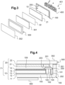
Fig. 3 ] est une vue explosée de l'ensemble afficheur de lafigure 2 ; - [
Fig. 4 ] est une vue en coupe transversale de l'ensemble afficheur de lafigure 2 montrant comment le dispositif d'affichage est monté dans le boîtier de montage ; - [
Fig. 5 ] est une vue partielle en coupe transversale du boîtier de montage de I afigure 4 ; - [
Fig. 6 ] est une vue en perspective arrière de l'ensemble afficheur de lafigure 2 avec une pièce de fixation assemblée sur celui-ci ; et - [
Fig. 7 ] est une vue éclatée de lafigure 6 montrant l'ensemble afficheur et la pièce de fixation séparés. - Sur la
figure 2 , on a représenté un ensemble afficheur 1 comportant un dispositif d'affichage 2 monté dans un boîtier de montage 100 selon un mode de réalisation préféré de l'invention. - La
figure 4 montre comment ce dispositif d'affichage 2 est monté dans ce boîtier de montage 100. - De manière connue, le dispositif d'affichage 2 comporte d'une part une source lumineuse sous la forme d'une unité 10 de rétro-éclairage (« backlight unit » en anglais) et, d'autre part, un écran 20.
- L'unité 10 de rétro-éclairage est conçue pour illuminer de manière homogène (luminance constante) la surface de l'écran 20 qui est un dispositif actif qui va moduler la lumière le traversant.
- Typiquement, et comme cela est visible sur la
figure 4 , l'unité 10 de rétro-éclairage est formée par l'empilement, les uns sur les autres, de différents composants « optiques » fonctionnels : - un film réfléchissant 11 (par exemple de type « Enhanced Specular Reflector » chez 3M) ;
- un guide de lumière 12 transparent (substrat polycarbonate ou PMMA par exemple) ;
- un film diffuseur 13, par exemple un film texturé ;
- un (ou deux) film(s) de type BEF 14 (« Brightness Enhancement Film » de la gamme Vikuiti chez 3M) ; et
- un film de type DBEF 15 (« Dual Brightness Enhancement Film » aussi chez 3M).
- De préférence, le guide de lumière 12 a ici la forme d'une plaque transparente et est éclairé sur au moins l'une de ses tranches (ici dans le logement 105) par un ensemble (« barrette ») de diodes électroluminescentes (LED) blanches (non visibles sur la figure) de sorte que la lumière émise par ces diodes se couple et se propage dans le guide de lumière 12. Cette lumière est réfléchie d'un côté par le film réfléchissant 11 et extraite de l'autre côté par le film diffuseur 13. Elle est ensuite redirigée et polarisée en direction de l'écran 20 grâce aux films de type BEF et DBEF respectivement.
- L'écran 20 comprend ici une matrice TFT-LCD 21 (comportant ici au moins un polariseur, non représenté) et une couche de colle transparente 22 (colle silicone ou acrylique du type « optically clear resin ») qui permet de fixer l'écran 20 sur un verre de façade 300 de l'ensemble afficheur 1 (voir ci-après).
- Comme le montrent les
figures 4 et5 , le boîtier de montage 100 comporte : - une paroi de fond 103, ici sensiblement rectangulaire ;
- une paroi latérale s'élevant depuis la paroi de fond 103 pour former un premier rebord 101 (de hauteur H1 et perpendiculaire à la surface de fond 103, cf.
figure 5 , la hauteur H1 étant mesurée perpendiculairement depuis la face arrière de la paroi de fond 103) et délimiter un logement de réception 109 destiné à accueillir au moins partiellement le dispositif d'affichage 2. - Avantageusement, le boîtier de montage 100 est réalisé en métal (par exemple en magnésium ou en aluminium) et la paroi de fond 103 du boîtier de montage 100 présente une épaisseur E3 (voir
fig. 5 ) comprise entre 2 et 3 millimètres. Cette épaisseur E3 est suffisante pour assurer une bonne rigidité de la paroi de fond 103 afin de résister aux efforts de torsion pouvant s'exercer sur le boîtier de montage 100. - Le boîtier de montage 100 comprend également un deuxième rebord 102 s'élevant à l'intérieur du logement de réception 109 depuis la paroi de fond 103, la hauteur - ici notée H2 (voir
fig. 5 , H2 est mesurée depuis la face arrière de la paroi de fond 103) - du deuxième rebord 102 étant inférieure à la hauteur H1 du premier rebord 101 du boîtier de montage 100. En d'autres termes, on pourrait dire que le profil périphérique du boîtier de montage 100 est en forme de U asymétrique, les deux rebords représentant les deux branches du U asymétrique. - Ainsi, le deuxième rebord 102 offre une surface d'attache pour un cadre métallique 200 destiné à maintenir l'unité 10 de rétro-éclairage par rapport au boitier de montage 100. Ce deuxième rebord 102 forme donc un moyen de montage du dispositif d'affichage 2 au boîtier de montage 100. Il coopère avec le cadre métallique 200 pour fixer au moins l'unité 10 dans le logement de réception 109 (en formant ici une butée pour l'unité 10 dans la direction d'extension du deuxième rebord 102). Dans le mode de réalisation décrit ici, le dispositif de rétro-éclairage 10 est donc entouré à sa périphérie par le deuxième rebord 102.
- Avantageusement, le rapport entre la hauteur H2 du deuxième rebord 102 et la hauteur H1 du premier rebord 101 est compris entre 0,3 et 0,7. Ce rapport de hauteur H2/H1 - qui est ici de 0,69 - permet d'avoir un écart suffisamment important entre le haut du premier rebord 101 et le haut du deuxième rebord 102 pour pouvoir y loger le cadre métallique 200, la mousse 201 et l'écran 20.
- De la même manière, le premier rebord 101 et le deuxième rebord 102 présentant respectivement une première épaisseur E1 et une deuxième épaisseur E2 (voir
figure 5 ), le rapport entre la deuxième épaisseur E2 et la première épaisseur E1 est compris entre 0,3 et 0,9. - En pratique, la première épaisseur E1 doit être plus importante que la deuxième épaisseur E2 afin d'assurer une surface de collage de taille suffisante avec le verre de façade 300. En d'autres termes, la deuxième épaisseur E2 forme ici une butée pour le cadre métallique 200.
- De préférence, la distance D12 entre le premier rebord 101 et le deuxième rebord 102 (c'est-à-dire la largeur de la gorge 104) est comprise entre 1 et 2 millimètres. Ceci crée un jeu fonctionnel permettant le montage du cadre métallique 200.
- Avantageusement, le cadre métallique 200 (parfois appelé « bezel » en anglais) présente un profil en « L inversé » ayant une première partie 202 verticale (la jambe du « L » inversé) et une deuxième partie 203 horizontale (le pied du « L » inversé) de manière à venir s'emboîter dans la rainure 104 formée entre les deux rebords 101, 102 (voir
fig. 4 ). - En d'autres termes, la première partie 202 s'insère dans la gorge 104 formée entre le premier rebord 101 et le deuxième rebord 102 et la deuxième partie 203 vient pincer le dispositif de rétro-éclairage 10 contre la paroi de fond 103.
- En pratique, pour fixer l'unité 10 de rétro-éclairage dans le boîtier de montage 100, on insère tout d'abord celle-ci dans le logement de réception 109 et on vient monter le cadre métallique 200 sur le deuxième rebord 102, par exemple par clipsage ou par collage.
- La partie horizontale 203 du cadre métallique 200 (i.e. la base du « L inversé ») repose alors sur le deuxième rebord 102 et vient ici par-dessus le film de type DBEF pour maintenir l'unité 10 en place au fond du logement 109.
- Dans un mode de réalisation préféré, on pourrait prévoir que le deuxième rebord 102 soit un élément de support pour les diodes électro-luminescentes de l'unité 10 de rétro-éclairage, ce qui permet une bonne dissipation thermique de la chaleur générée par les diodes.
- Une mousse 201 souple de faible dimension, typiquement d'épaisseur inférieure au millimètre, est de préférence collée sur la partie horizontale 203 du cadre métallique 200. Cette mousse 201 doit être en contact avec l'ensemble formé du verre de façade 300 et de l'écran 20 sans toutefois générer de contrainte mécanique trop forte sur la dalle TFT-LCD 21.
- Cet ensemble est collé par les bords de cette structure par au moins trois cotés sur l'extrémité libre du premier rebord 101 du boîtier de montage 100. Le collage est réalisé, soit par un adhésif 301 de type double face (comme c'est le cas du mode de réalisation représenté sur la
figure 4 ), soit par une colle structurelle, par exemple une colle silicone UV polymérisé par éclairement UV sur le bord de l'assemblage. - Pour permettre un collage efficace, la première épaisseur E1 du premier rebord 101 est comprise entre 1 millimètre et 3 millimètres. Ceci permet de fournir une surface suffisante pour le collage du verre de façade 300 sur le premier rebord 101.
- Avantageusement, le verre de façade 300 peut comprendre un ou plusieurs films fonctionnels, par exemple un film de type « touch panel », un film anti-éblouissement (« anti-glare film »), un film polarisant, un film anti-reflet, etc....
- Grâce à l'invention, il est possible de réaliser un afficheur automobile d'une épaisseur inférieure à 10 millimètres, par exemple inférieure à 8,2 millimètres (dimension excluant le verre de façade, voir
figure 5 ), supportant des efforts de traction et de torsion compatibles avec certains usages automobiles, et disposant d'une façade complémentaire réalisant une fonction décorative. - De préférence, l'ensemble afficheur 1 comporte un support de fixation 400 tel que représenté sur les
figures 6 et 7 . - Ce support de fixation 400 permet de centrer et fixer l'ensemble afficheur 1 par exemple sur la planche de bord d'un véhicule automobile.
- De plus, une fois fixé, ce support de fixation 400 assure une fonction de rigidification et permet la tenue mécanique de l'ensemble afficheur 1 lorsque celui-ci est soumis à des contraintes mécaniques par déformation de la planche de bord (roulement sur un dos d'âne ou un coussin berlinois par exemple).
- Avantageusement, l'arrière de la paroi de fond 103 du boîtier de montage 100 comprend des pions de centrage 115, 116, 117 coopérant avec des moyens de fixation du support de fixation 400, comprenant ici des ouvertures 403, 404, 405 de centrage. Ce support de fixation 400 peut alors être assemblé sur le boîtier de montage 100 au moyen de vis 401 venant se visser dans des puits taraudés 118 dans la paroi de fond 103.
- Le support de fixation 400 comprend en outre des moyens de montage sur une planche de bord d'un véhicule automobile, ces moyens de montage incluant ici des ergots 402 (voir
figure 6 ) venant par exemple se clipser dans des trous formés dans la planche de bord. - Le fait que le support de fixation 400 soit indépendant du boîtier de montage 100 permet de réaliser un choix et une variété dans le type de fixation finale utilisé pour l'ensemble afficheur 1 sur la planche de bord.
Claims (12)
- Boîtier de montage (100) pour un dispositif d'affichage (2) comprenant une unité (10) de rétro-éclairage et un écran (20), ledit boîtier de montage (100) comportant :- une paroi de fond (103) ;- une paroi latérale (101) s'élevant depuis la paroi de fond (103) pour former un premier rebord (101) et délimiter un logement de réception (109) destiné à accueillir au moins partiellement ledit dispositif d'affichage (2) ;- des moyens de montage (102) destinés à coopérer avec des moyens de montage complémentaires (200) dudit dispositif d'affichage (2) pour fixer au moins ladite unité (10) dans ledit logement de réception, lesdits moyens de montage comprenant un deuxième rebord (102) s'élevant depuis la paroi de fond (103), la hauteur (H2) du deuxième rebord (102) étant inférieure à la hauteur (H1) dudit premier rebord (101), de sorte que le profil périphérique du boîtier de montage (100) est en forme de U asymétrique, les deux rebords représentant les deux branches du U asymétrique,caractérisé en ce que le deuxième rebord (102) s'élève à l'intérieur dudit logement de réception (109), le rapport entre la hauteur (H2) du deuxième rebord (102) et la hauteur (H1) dudit premier rebord (101) étant compris entre 0,3 et 0,7.
- Boîtier de montage (100) selon la revendication 1, dans lequel, ledit premier rebord (101) et le deuxième rebord (102) présentant respectivement une première épaisseur (E1) et une deuxième épaisseur (E2), le rapport entre la deuxième épaisseur (E2) et la première épaisseur (E1) est compris entre 0,3 et 0,9.
- Boîtier de montage (100) selon l'une des revendications 1 ou 2, dans lequel la première épaisseur (E1) du premier rebord est comprise entre 1 millimètre et 3 millimètres.
- Boîtier de montage (100) selon l'une des revendications 1 à 3, dans lequel la distance (D12) entre le premier rebord (101) et le deuxième rebord (102) est comprise entre 1 et 2 millimètres.
- Boîtier de montage (100) selon l'une des revendications 1 à 4, dans lequel la paroi de fond (103) dudit boîtier de montage (100) présente une épaisseur comprise entre 2 et 3 millimètres.
- Boîtier de montage (100) selon l'une des revendications 1 à 5, comportant en outre un cadre métallique (200) adapté à se fixer sur ledit deuxième rebord (102) pour maintenir ladite unité (10) de rétro-éclairage par rapport au boîtier de montage (100).
- Boîtier de montage (100) selon la revendication 6, dans lequel ledit cadre métallique (200) présente un profil en L inversé ayant une première partie (202) et une deuxième partie (203), ladite première partie (202) s'insérant dans une gorge (104) formée entre le premier rebord (101) et le deuxième rebord (102) et ladite deuxième partie (203) venant pincer le dispositif de rétro-éclairage (10) contre la paroi de fond (103).
- Boîtier de montage (100) selon l'une des revendications 1 à 7, dans lequel ledit dispositif de rétro-éclairage (10) est entouré à sa périphérie par ledit deuxième rebord (102).
- Ensemble afficheur (1) comportant un dispositif d'affichage (2) et un boîtier de montage (100) selon l'une des revendications 1 à 8 destiné à recevoir ledit dispositif d'affichage (2).
- Ensemble afficheur (1) selon la revendication 9, comportant en outre un verre de façade (300) destiné à fermer le logement de réception (109) dudit boîtier de montage (100), ledit verre de façade (300) étant fixé au boîtier de montage (100) au niveau dudit premier rebord (101).
- Ensemble afficheur (1) selon la revendication 10, dans lequel ledit écran (20) est situé entre ledit deuxième rebord (102) et ledit verre de façade (300).
- Ensemble afficheur (1) selon l'une des revendications 9 à 11 comportant en outre un support de fixation (400) avec des moyens de fixation (403, 404, 405) sur ledit boîtier de montage (100) et des moyens de montage (402) sur une planche de bord d'un véhicule automobile.
Applications Claiming Priority (2)
| Application Number | Priority Date | Filing Date | Title |
|---|---|---|---|
| FR1901779A FR3093262B1 (fr) | 2019-02-21 | 2019-02-21 | Boîtier de montage pour dispositif d’affichage et ensemble afficheur comportant un tel boîtier |
| PCT/EP2020/052865 WO2020169345A1 (fr) | 2019-02-21 | 2020-02-05 | Boîtier de montage pour dispositif d'affichage et ensemble afficheur comportant un tel boîtier |
Publications (2)
| Publication Number | Publication Date |
|---|---|
| EP3928153A1 EP3928153A1 (fr) | 2021-12-29 |
| EP3928153B1 true EP3928153B1 (fr) | 2024-09-11 |
Family
ID=68072484
Family Applications (1)
| Application Number | Title | Priority Date | Filing Date |
|---|---|---|---|
| EP20703992.6A Active EP3928153B1 (fr) | 2019-02-21 | 2020-02-05 | Boitier de montage pour dispositif d'affichage et ensemble afficheur comportant un tel boitier |
Country Status (3)
| Country | Link |
|---|---|
| EP (1) | EP3928153B1 (fr) |
| FR (1) | FR3093262B1 (fr) |
| WO (1) | WO2020169345A1 (fr) |
Families Citing this family (1)
| Publication number | Priority date | Publication date | Assignee | Title |
|---|---|---|---|---|
| CN115113437B (zh) * | 2022-08-03 | 2024-05-14 | 奇瑞汽车股份有限公司 | 车载显示屏及车辆 |
Citations (1)
| Publication number | Priority date | Publication date | Assignee | Title |
|---|---|---|---|---|
| WO2015066942A1 (fr) * | 2013-11-05 | 2015-05-14 | 深圳市华星光电技术有限公司 | Appareil d'affichage à cristaux liquides sans cadre |
Family Cites Families (3)
| Publication number | Priority date | Publication date | Assignee | Title |
|---|---|---|---|---|
| CN102376199A (zh) * | 2010-08-11 | 2012-03-14 | 鸿富锦精密工业(深圳)有限公司 | 显示装置 |
| KR20120071751A (ko) * | 2010-12-23 | 2012-07-03 | 엘지디스플레이 주식회사 | 디스플레이 장치 |
| US9927642B2 (en) * | 2015-06-18 | 2018-03-27 | Ford Global Technologies, Llc | Vehicle display unit |
-
2019
- 2019-02-21 FR FR1901779A patent/FR3093262B1/fr active Active
-
2020
- 2020-02-05 WO PCT/EP2020/052865 patent/WO2020169345A1/fr not_active Ceased
- 2020-02-05 EP EP20703992.6A patent/EP3928153B1/fr active Active
Patent Citations (1)
| Publication number | Priority date | Publication date | Assignee | Title |
|---|---|---|---|---|
| WO2015066942A1 (fr) * | 2013-11-05 | 2015-05-14 | 深圳市华星光电技术有限公司 | Appareil d'affichage à cristaux liquides sans cadre |
Also Published As
| Publication number | Publication date |
|---|---|
| FR3093262B1 (fr) | 2021-11-19 |
| FR3093262A1 (fr) | 2020-08-28 |
| WO2020169345A1 (fr) | 2020-08-27 |
| EP3928153A1 (fr) | 2021-12-29 |
Similar Documents
| Publication | Publication Date | Title |
|---|---|---|
| EP3365596B1 (fr) | Dispositif d'éclairage et/ou de signalisation compact pour véhicule | |
| EP4065882B1 (fr) | Module lumineux d'un véhicule automobile équipé d'un élément optique | |
| EP1566686A1 (fr) | Dispositif de rétro-éclairage pour élément d'affichage | |
| EP3301355B1 (fr) | Procédé d' obtention d'un ensemble de diffusion de lumière, notamment pour véhicule automobile | |
| EP3928153B1 (fr) | Boitier de montage pour dispositif d'affichage et ensemble afficheur comportant un tel boitier | |
| EP3479156B1 (fr) | Dispositif de génération d'images comprenant une zone de contact thermique, et afficheur tête haute associé | |
| FR3121087A1 (fr) | Dispositif d’affichage | |
| EP3491444B1 (fr) | Dispositif de génération d'images et afficheur tête haute associé | |
| FR3078559A1 (fr) | Dispositif d’eclairage de vehicule, a masque a nervures de limitation de sortie de photons de guides de lumiere. | |
| EP3631563B1 (fr) | Afficheur tête haute pour véhicule automobile | |
| EP3440504A1 (fr) | Dispositif de génération d'image, afficheur tête haute comprenant un tel dispositif et procédé de fabrication d'un dispositif de génération d'image | |
| EP3315857B1 (fr) | Guide de lumière coudé amélioré | |
| EP3074275A1 (fr) | Lunette arrière en matière plastique pour véhicule automobile équipée d'un troisième feu stop | |
| FR3117953A1 (fr) | Dispositif d’affichage courbé | |
| FR3079599A1 (fr) | Dispositif de signalisation lumineuse avec ecran lcd | |
| EP4214079B1 (fr) | Dispositif d'affichage | |
| FR2683071A1 (fr) | Dispositif d'affichage retroeclaire, notamment afficheur a cristaux liquides retroeclaire, et procede de fabrication d'une feuille diffusante pour un tel dispositif. | |
| WO2003001110A1 (fr) | Dispositif optique, notamment imageur a cristaux liquides, et miroir associe | |
| EP4370375B1 (fr) | Module lumineux de véhicule automobile comprenant un organe de maintien de l'optique de projection | |
| FR3132577A1 (fr) | Dispositif de rétroéclairage, dispositif de génération d’images, afficheur tête haute et procédé de fabrication associés | |
| EP4232866A1 (fr) | Dispositif d'assemblage adapté pour assembler un écran avec un élément partiellement transparent et afficheur tête haute comprenant un tel dispositif | |
| WO2023118543A1 (fr) | Ensemble pour dispositif lumineux d'un vehicule automobile et procédé de montage | |
| CH697569B1 (fr) | Dispositif de rétro-éclairage d'un élément d'affichage d'information d'un objet portable. | |
| FR3078767A1 (fr) | Dispositif de retro-eclairage et dispositif d'affichage associe | |
| FR3066836A1 (fr) | Dispositif de generation d'images pour vehicule automobile et afficheur tete haute associe |
Legal Events
| Date | Code | Title | Description |
|---|---|---|---|
| STAA | Information on the status of an ep patent application or granted ep patent |
Free format text: STATUS: UNKNOWN |
|
| STAA | Information on the status of an ep patent application or granted ep patent |
Free format text: STATUS: THE INTERNATIONAL PUBLICATION HAS BEEN MADE |
|
| PUAI | Public reference made under article 153(3) epc to a published international application that has entered the european phase |
Free format text: ORIGINAL CODE: 0009012 |
|
| STAA | Information on the status of an ep patent application or granted ep patent |
Free format text: STATUS: REQUEST FOR EXAMINATION WAS MADE |
|
| 17P | Request for examination filed |
Effective date: 20210827 |
|
| AK | Designated contracting states |
Kind code of ref document: A1 Designated state(s): AL AT BE BG CH CY CZ DE DK EE ES FI FR GB GR HR HU IE IS IT LI LT LU LV MC MK MT NL NO PL PT RO RS SE SI SK SM TR |
|
| DAV | Request for validation of the european patent (deleted) | ||
| DAX | Request for extension of the european patent (deleted) | ||
| RAP3 | Party data changed (applicant data changed or rights of an application transferred) |
Owner name: VALEO COMFORT AND DRIVING ASSISTANCE |
|
| P01 | Opt-out of the competence of the unified patent court (upc) registered |
Effective date: 20230528 |
|
| STAA | Information on the status of an ep patent application or granted ep patent |
Free format text: STATUS: EXAMINATION IS IN PROGRESS |
|
| 17Q | First examination report despatched |
Effective date: 20230922 |
|
| RAP3 | Party data changed (applicant data changed or rights of an application transferred) |
Owner name: VALEO COMFORT AND DRIVING ASSISTANCE |
|
| GRAP | Despatch of communication of intention to grant a patent |
Free format text: ORIGINAL CODE: EPIDOSNIGR1 |
|
| STAA | Information on the status of an ep patent application or granted ep patent |
Free format text: STATUS: GRANT OF PATENT IS INTENDED |
|
| INTG | Intention to grant announced |
Effective date: 20240507 |
|
| GRAS | Grant fee paid |
Free format text: ORIGINAL CODE: EPIDOSNIGR3 |
|
| GRAA | (expected) grant |
Free format text: ORIGINAL CODE: 0009210 |
|
| STAA | Information on the status of an ep patent application or granted ep patent |
Free format text: STATUS: THE PATENT HAS BEEN GRANTED |
|
| AK | Designated contracting states |
Kind code of ref document: B1 Designated state(s): AL AT BE BG CH CY CZ DE DK EE ES FI FR GB GR HR HU IE IS IT LI LT LU LV MC MK MT NL NO PL PT RO RS SE SI SK SM TR |
|
| REG | Reference to a national code |
Ref country code: GB Ref legal event code: FG4D Free format text: NOT ENGLISH |
|
| REG | Reference to a national code |
Ref country code: CH Ref legal event code: EP |
|
| REG | Reference to a national code |
Ref country code: DE Ref legal event code: R096 Ref document number: 602020037486 Country of ref document: DE |
|
| REG | Reference to a national code |
Ref country code: IE Ref legal event code: FG4D Free format text: LANGUAGE OF EP DOCUMENT: FRENCH |
|
| REG | Reference to a national code |
Ref country code: LT Ref legal event code: MG9D |
|
| PG25 | Lapsed in a contracting state [announced via postgrant information from national office to epo] |
Ref country code: NO Free format text: LAPSE BECAUSE OF FAILURE TO SUBMIT A TRANSLATION OF THE DESCRIPTION OR TO PAY THE FEE WITHIN THE PRESCRIBED TIME-LIMIT Effective date: 20241211 |
|
| REG | Reference to a national code |
Ref country code: NL Ref legal event code: MP Effective date: 20240911 |
|
| PG25 | Lapsed in a contracting state [announced via postgrant information from national office to epo] |
Ref country code: GR Free format text: LAPSE BECAUSE OF FAILURE TO SUBMIT A TRANSLATION OF THE DESCRIPTION OR TO PAY THE FEE WITHIN THE PRESCRIBED TIME-LIMIT Effective date: 20241212 Ref country code: FI Free format text: LAPSE BECAUSE OF FAILURE TO SUBMIT A TRANSLATION OF THE DESCRIPTION OR TO PAY THE FEE WITHIN THE PRESCRIBED TIME-LIMIT Effective date: 20240911 |
|
| PG25 | Lapsed in a contracting state [announced via postgrant information from national office to epo] |
Ref country code: BG Free format text: LAPSE BECAUSE OF FAILURE TO SUBMIT A TRANSLATION OF THE DESCRIPTION OR TO PAY THE FEE WITHIN THE PRESCRIBED TIME-LIMIT Effective date: 20240911 |
|
| PG25 | Lapsed in a contracting state [announced via postgrant information from national office to epo] |
Ref country code: LV Free format text: LAPSE BECAUSE OF FAILURE TO SUBMIT A TRANSLATION OF THE DESCRIPTION OR TO PAY THE FEE WITHIN THE PRESCRIBED TIME-LIMIT Effective date: 20240911 |
|
| PG25 | Lapsed in a contracting state [announced via postgrant information from national office to epo] |
Ref country code: HR Free format text: LAPSE BECAUSE OF FAILURE TO SUBMIT A TRANSLATION OF THE DESCRIPTION OR TO PAY THE FEE WITHIN THE PRESCRIBED TIME-LIMIT Effective date: 20240911 |
|
| PG25 | Lapsed in a contracting state [announced via postgrant information from national office to epo] |
Ref country code: ES Free format text: LAPSE BECAUSE OF FAILURE TO SUBMIT A TRANSLATION OF THE DESCRIPTION OR TO PAY THE FEE WITHIN THE PRESCRIBED TIME-LIMIT Effective date: 20240911 Ref country code: RS Free format text: LAPSE BECAUSE OF FAILURE TO SUBMIT A TRANSLATION OF THE DESCRIPTION OR TO PAY THE FEE WITHIN THE PRESCRIBED TIME-LIMIT Effective date: 20241211 |
|
| PG25 | Lapsed in a contracting state [announced via postgrant information from national office to epo] |
Ref country code: RS Free format text: LAPSE BECAUSE OF FAILURE TO SUBMIT A TRANSLATION OF THE DESCRIPTION OR TO PAY THE FEE WITHIN THE PRESCRIBED TIME-LIMIT Effective date: 20241211 Ref country code: NO Free format text: LAPSE BECAUSE OF FAILURE TO SUBMIT A TRANSLATION OF THE DESCRIPTION OR TO PAY THE FEE WITHIN THE PRESCRIBED TIME-LIMIT Effective date: 20241211 Ref country code: LV Free format text: LAPSE BECAUSE OF FAILURE TO SUBMIT A TRANSLATION OF THE DESCRIPTION OR TO PAY THE FEE WITHIN THE PRESCRIBED TIME-LIMIT Effective date: 20240911 Ref country code: HR Free format text: LAPSE BECAUSE OF FAILURE TO SUBMIT A TRANSLATION OF THE DESCRIPTION OR TO PAY THE FEE WITHIN THE PRESCRIBED TIME-LIMIT Effective date: 20240911 Ref country code: GR Free format text: LAPSE BECAUSE OF FAILURE TO SUBMIT A TRANSLATION OF THE DESCRIPTION OR TO PAY THE FEE WITHIN THE PRESCRIBED TIME-LIMIT Effective date: 20241212 Ref country code: FI Free format text: LAPSE BECAUSE OF FAILURE TO SUBMIT A TRANSLATION OF THE DESCRIPTION OR TO PAY THE FEE WITHIN THE PRESCRIBED TIME-LIMIT Effective date: 20240911 Ref country code: ES Free format text: LAPSE BECAUSE OF FAILURE TO SUBMIT A TRANSLATION OF THE DESCRIPTION OR TO PAY THE FEE WITHIN THE PRESCRIBED TIME-LIMIT Effective date: 20240911 Ref country code: BG Free format text: LAPSE BECAUSE OF FAILURE TO SUBMIT A TRANSLATION OF THE DESCRIPTION OR TO PAY THE FEE WITHIN THE PRESCRIBED TIME-LIMIT Effective date: 20240911 |
|
| REG | Reference to a national code |
Ref country code: AT Ref legal event code: MK05 Ref document number: 1723203 Country of ref document: AT Kind code of ref document: T Effective date: 20240911 |
|
| PG25 | Lapsed in a contracting state [announced via postgrant information from national office to epo] |
Ref country code: NL Free format text: LAPSE BECAUSE OF FAILURE TO SUBMIT A TRANSLATION OF THE DESCRIPTION OR TO PAY THE FEE WITHIN THE PRESCRIBED TIME-LIMIT Effective date: 20240911 |
|
| PG25 | Lapsed in a contracting state [announced via postgrant information from national office to epo] |
Ref country code: IS Free format text: LAPSE BECAUSE OF FAILURE TO SUBMIT A TRANSLATION OF THE DESCRIPTION OR TO PAY THE FEE WITHIN THE PRESCRIBED TIME-LIMIT Effective date: 20250111 Ref country code: PT Free format text: LAPSE BECAUSE OF FAILURE TO SUBMIT A TRANSLATION OF THE DESCRIPTION OR TO PAY THE FEE WITHIN THE PRESCRIBED TIME-LIMIT Effective date: 20250113 |
|
| PG25 | Lapsed in a contracting state [announced via postgrant information from national office to epo] |
Ref country code: RO Free format text: LAPSE BECAUSE OF FAILURE TO SUBMIT A TRANSLATION OF THE DESCRIPTION OR TO PAY THE FEE WITHIN THE PRESCRIBED TIME-LIMIT Effective date: 20240911 Ref country code: SM Free format text: LAPSE BECAUSE OF FAILURE TO SUBMIT A TRANSLATION OF THE DESCRIPTION OR TO PAY THE FEE WITHIN THE PRESCRIBED TIME-LIMIT Effective date: 20240911 |
|
| PG25 | Lapsed in a contracting state [announced via postgrant information from national office to epo] |
Ref country code: EE Free format text: LAPSE BECAUSE OF FAILURE TO SUBMIT A TRANSLATION OF THE DESCRIPTION OR TO PAY THE FEE WITHIN THE PRESCRIBED TIME-LIMIT Effective date: 20240911 Ref country code: AT Free format text: LAPSE BECAUSE OF FAILURE TO SUBMIT A TRANSLATION OF THE DESCRIPTION OR TO PAY THE FEE WITHIN THE PRESCRIBED TIME-LIMIT Effective date: 20240911 |
|
| PG25 | Lapsed in a contracting state [announced via postgrant information from national office to epo] |
Ref country code: CZ Free format text: LAPSE BECAUSE OF FAILURE TO SUBMIT A TRANSLATION OF THE DESCRIPTION OR TO PAY THE FEE WITHIN THE PRESCRIBED TIME-LIMIT Effective date: 20240911 Ref country code: PL Free format text: LAPSE BECAUSE OF FAILURE TO SUBMIT A TRANSLATION OF THE DESCRIPTION OR TO PAY THE FEE WITHIN THE PRESCRIBED TIME-LIMIT Effective date: 20240911 |
|
| PG25 | Lapsed in a contracting state [announced via postgrant information from national office to epo] |
Ref country code: SK Free format text: LAPSE BECAUSE OF FAILURE TO SUBMIT A TRANSLATION OF THE DESCRIPTION OR TO PAY THE FEE WITHIN THE PRESCRIBED TIME-LIMIT Effective date: 20240911 Ref country code: IT Free format text: LAPSE BECAUSE OF FAILURE TO SUBMIT A TRANSLATION OF THE DESCRIPTION OR TO PAY THE FEE WITHIN THE PRESCRIBED TIME-LIMIT Effective date: 20240911 |
|
| REG | Reference to a national code |
Ref country code: DE Ref legal event code: R097 Ref document number: 602020037486 Country of ref document: DE |
|
| PG25 | Lapsed in a contracting state [announced via postgrant information from national office to epo] |
Ref country code: DK Free format text: LAPSE BECAUSE OF FAILURE TO SUBMIT A TRANSLATION OF THE DESCRIPTION OR TO PAY THE FEE WITHIN THE PRESCRIBED TIME-LIMIT Effective date: 20240911 |
|
| PLBE | No opposition filed within time limit |
Free format text: ORIGINAL CODE: 0009261 |
|
| STAA | Information on the status of an ep patent application or granted ep patent |
Free format text: STATUS: NO OPPOSITION FILED WITHIN TIME LIMIT |
|
| 26N | No opposition filed |
Effective date: 20250612 |
|
| PG25 | Lapsed in a contracting state [announced via postgrant information from national office to epo] |
Ref country code: SE Free format text: LAPSE BECAUSE OF FAILURE TO SUBMIT A TRANSLATION OF THE DESCRIPTION OR TO PAY THE FEE WITHIN THE PRESCRIBED TIME-LIMIT Effective date: 20240911 |
|
| PG25 | Lapsed in a contracting state [announced via postgrant information from national office to epo] |
Ref country code: MC Free format text: LAPSE BECAUSE OF FAILURE TO SUBMIT A TRANSLATION OF THE DESCRIPTION OR TO PAY THE FEE WITHIN THE PRESCRIBED TIME-LIMIT Effective date: 20240911 |
|
| REG | Reference to a national code |
Ref country code: CH Ref legal event code: PL |
|
| PG25 | Lapsed in a contracting state [announced via postgrant information from national office to epo] |
Ref country code: LU Free format text: LAPSE BECAUSE OF NON-PAYMENT OF DUE FEES Effective date: 20250205 |
|
| PG25 | Lapsed in a contracting state [announced via postgrant information from national office to epo] |
Ref country code: CH Free format text: LAPSE BECAUSE OF NON-PAYMENT OF DUE FEES Effective date: 20250228 |
|
| GBPC | Gb: european patent ceased through non-payment of renewal fee |
Effective date: 20250205 |
|
| REG | Reference to a national code |
Ref country code: BE Ref legal event code: MM Effective date: 20250228 |
|
| PG25 | Lapsed in a contracting state [announced via postgrant information from national office to epo] |
Ref country code: GB Free format text: LAPSE BECAUSE OF NON-PAYMENT OF DUE FEES Effective date: 20250205 |
|
| PG25 | Lapsed in a contracting state [announced via postgrant information from national office to epo] |
Ref country code: BE Free format text: LAPSE BECAUSE OF NON-PAYMENT OF DUE FEES Effective date: 20250228 |
|
| PG25 | Lapsed in a contracting state [announced via postgrant information from national office to epo] |
Ref country code: IE Free format text: LAPSE BECAUSE OF NON-PAYMENT OF DUE FEES Effective date: 20250205 |
|
| PGFP | Annual fee paid to national office [announced via postgrant information from national office to epo] |
Ref country code: DE Payment date: 20260206 Year of fee payment: 7 |
|
| PGFP | Annual fee paid to national office [announced via postgrant information from national office to epo] |
Ref country code: FR Payment date: 20260227 Year of fee payment: 7 |