EP3928121B1 - Ultraschallbildgebung mit deep-learning basierter strahlformung sowie zugehörige vorrichtungen, systeme und verfahren - Google Patents
Ultraschallbildgebung mit deep-learning basierter strahlformung sowie zugehörige vorrichtungen, systeme und verfahren Download PDFInfo
- Publication number
- EP3928121B1 EP3928121B1 EP20704830.7A EP20704830A EP3928121B1 EP 3928121 B1 EP3928121 B1 EP 3928121B1 EP 20704830 A EP20704830 A EP 20704830A EP 3928121 B1 EP3928121 B1 EP 3928121B1
- Authority
- EP
- European Patent Office
- Prior art keywords
- ultrasound
- data
- beamformed
- channel data
- ultrasound channel
- Prior art date
- Legal status (The legal status is an assumption and is not a legal conclusion. Google has not performed a legal analysis and makes no representation as to the accuracy of the status listed.)
- Active
Links
Images






Classifications
-
- G—PHYSICS
- G01—MEASURING; TESTING
- G01S—RADIO DIRECTION-FINDING; RADIO NAVIGATION; DETERMINING DISTANCE OR VELOCITY BY USE OF RADIO WAVES; LOCATING OR PRESENCE-DETECTING BY USE OF THE REFLECTION OR RERADIATION OF RADIO WAVES; ANALOGOUS ARRANGEMENTS USING OTHER WAVES
- G01S15/00—Systems using the reflection or reradiation of acoustic waves, e.g. sonar systems
- G01S15/88—Sonar systems specially adapted for specific applications
- G01S15/89—Sonar systems specially adapted for specific applications for mapping or imaging
- G01S15/8906—Short-range imaging systems; Acoustic microscope systems using pulse-echo techniques
- G01S15/8909—Short-range imaging systems; Acoustic microscope systems using pulse-echo techniques using a static transducer configuration
- G01S15/8915—Short-range imaging systems; Acoustic microscope systems using pulse-echo techniques using a static transducer configuration using a transducer array
-
- A—HUMAN NECESSITIES
- A61—MEDICAL OR VETERINARY SCIENCE; HYGIENE
- A61B—DIAGNOSIS; SURGERY; IDENTIFICATION
- A61B8/00—Diagnosis using ultrasonic, sonic or infrasonic waves
- A61B8/52—Devices using data or image processing specially adapted for diagnosis using ultrasonic, sonic or infrasonic waves
- A61B8/5207—Devices using data or image processing specially adapted for diagnosis using ultrasonic, sonic or infrasonic waves involving processing of raw data to produce diagnostic data, e.g. for generating an image
-
- G—PHYSICS
- G01—MEASURING; TESTING
- G01S—RADIO DIRECTION-FINDING; RADIO NAVIGATION; DETERMINING DISTANCE OR VELOCITY BY USE OF RADIO WAVES; LOCATING OR PRESENCE-DETECTING BY USE OF THE REFLECTION OR RERADIATION OF RADIO WAVES; ANALOGOUS ARRANGEMENTS USING OTHER WAVES
- G01S7/00—Details of systems according to groups G01S13/00, G01S15/00, G01S17/00
- G01S7/52—Details of systems according to groups G01S13/00, G01S15/00, G01S17/00 of systems according to group G01S15/00
- G01S7/52017—Details of systems according to groups G01S13/00, G01S15/00, G01S17/00 of systems according to group G01S15/00 particularly adapted to short-range imaging
- G01S7/52023—Details of receivers
- G01S7/52025—Details of receivers for pulse systems
- G01S7/52026—Extracting wanted echo signals
- G01S7/52028—Extracting wanted echo signals using digital techniques
-
- G—PHYSICS
- G01—MEASURING; TESTING
- G01S—RADIO DIRECTION-FINDING; RADIO NAVIGATION; DETERMINING DISTANCE OR VELOCITY BY USE OF RADIO WAVES; LOCATING OR PRESENCE-DETECTING BY USE OF THE REFLECTION OR RERADIATION OF RADIO WAVES; ANALOGOUS ARRANGEMENTS USING OTHER WAVES
- G01S7/00—Details of systems according to groups G01S13/00, G01S15/00, G01S17/00
- G01S7/52—Details of systems according to groups G01S13/00, G01S15/00, G01S17/00 of systems according to group G01S15/00
- G01S7/52017—Details of systems according to groups G01S13/00, G01S15/00, G01S17/00 of systems according to group G01S15/00 particularly adapted to short-range imaging
- G01S7/52046—Techniques for image enhancement involving transmitter or receiver
- G01S7/52047—Techniques for image enhancement involving transmitter or receiver for elimination of side lobes or of grating lobes; for increasing resolving power
-
- G—PHYSICS
- G06—COMPUTING OR CALCULATING; COUNTING
- G06N—COMPUTING ARRANGEMENTS BASED ON SPECIFIC COMPUTATIONAL MODELS
- G06N3/00—Computing arrangements based on biological models
- G06N3/02—Neural networks
- G06N3/04—Architecture, e.g. interconnection topology
- G06N3/045—Combinations of networks
-
- G—PHYSICS
- G06—COMPUTING OR CALCULATING; COUNTING
- G06N—COMPUTING ARRANGEMENTS BASED ON SPECIFIC COMPUTATIONAL MODELS
- G06N3/00—Computing arrangements based on biological models
- G06N3/02—Neural networks
- G06N3/04—Architecture, e.g. interconnection topology
- G06N3/0464—Convolutional networks [CNN, ConvNet]
-
- G—PHYSICS
- G06—COMPUTING OR CALCULATING; COUNTING
- G06N—COMPUTING ARRANGEMENTS BASED ON SPECIFIC COMPUTATIONAL MODELS
- G06N3/00—Computing arrangements based on biological models
- G06N3/02—Neural networks
- G06N3/08—Learning methods
- G06N3/09—Supervised learning
-
- G—PHYSICS
- G06—COMPUTING OR CALCULATING; COUNTING
- G06T—IMAGE DATA PROCESSING OR GENERATION, IN GENERAL
- G06T7/00—Image analysis
- G06T7/0002—Inspection of images, e.g. flaw detection
- G06T7/0012—Biomedical image inspection
-
- G—PHYSICS
- G10—MUSICAL INSTRUMENTS; ACOUSTICS
- G10K—SOUND-PRODUCING DEVICES; METHODS OR DEVICES FOR PROTECTING AGAINST, OR FOR DAMPING, NOISE OR OTHER ACOUSTIC WAVES IN GENERAL; ACOUSTICS NOT OTHERWISE PROVIDED FOR
- G10K11/00—Methods or devices for transmitting, conducting or directing sound in general; Methods or devices for protecting against, or for damping, noise or other acoustic waves in general
- G10K11/18—Methods or devices for transmitting, conducting or directing sound
- G10K11/26—Sound-focusing or directing, e.g. scanning
- G10K11/34—Sound-focusing or directing, e.g. scanning using electrical steering of transducer arrays, e.g. beam steering
- G10K11/341—Circuits therefor
- G10K11/346—Circuits therefor using phase variation
-
- G—PHYSICS
- G06—COMPUTING OR CALCULATING; COUNTING
- G06T—IMAGE DATA PROCESSING OR GENERATION, IN GENERAL
- G06T2207/00—Indexing scheme for image analysis or image enhancement
- G06T2207/10—Image acquisition modality
- G06T2207/10132—Ultrasound image
- G06T2207/10136—3D ultrasound image
-
- G—PHYSICS
- G06—COMPUTING OR CALCULATING; COUNTING
- G06T—IMAGE DATA PROCESSING OR GENERATION, IN GENERAL
- G06T2207/00—Indexing scheme for image analysis or image enhancement
- G06T2207/20—Special algorithmic details
- G06T2207/20081—Training; Learning
-
- G—PHYSICS
- G06—COMPUTING OR CALCULATING; COUNTING
- G06T—IMAGE DATA PROCESSING OR GENERATION, IN GENERAL
- G06T2207/00—Indexing scheme for image analysis or image enhancement
- G06T2207/20—Special algorithmic details
- G06T2207/20084—Artificial neural networks [ANN]
Definitions
- the present disclosure relates generally to ultrasound imaging and, in particular, to reconstructing ultrasound images from ultrasound echo channel responses using a predictive model for beamforming.
- a conventional medical ultrasound system may include an ultrasound transducer probe coupled to a processing system and one or more display devices.
- the ultrasound transducer probe may include an array of acoustic elements that transmit acoustic waves into an object (e.g., a patient's body) and record acoustic waves reflected from the object.
- the transmission of the acoustic waves and/or the reception of reflected acoustic waves or echo responses can be performed by the same set of ultrasound transducer elements or different sets of acoustic elements.
- the processing system reconstructs or creates an image of the object from the echo responses received by the acoustic elements.
- the processing system may perform beamforming by delaying and summing the received echo response signals to achieve receive focusing along imaging depths.
- the processing system may reconstruct the image from the beamformed signals by applying signal processing and/or image processing techniques.
- image quality or resolution in conventional ultrasound imaging is limited by diffraction.
- One approach to reducing the effect of diffraction is to employ a transducer with a larger aperture size.
- an ultrasound imaging system may utilize unfocused ultrasound beams or diverging waves to illuminate a larger portion of a region of interest (ROI) with a single transmission in order to reduce image acquisition time.
- ROI region of interest
- images obtained from a limited number of diverging waves can have a lower image quality than images obtained from focused imaging.
- the ultrasound image quality in a conventional ultrasound imaging system can be limited by the capability (e.g., the transducer aperture size) of the system and/or the acquisition process.
- an imaging probe including a transducer array may be used for ultrasound imaging.
- the transducer array may include an array of acoustic elements that emit ultrasound pulses into an object (e.g., a patient's anatomy) and receive ultrasound channel signals corresponding to ultrasonic waves reflected from the object.
- a predictive network e.g., a convolutional neural network (CNN)
- CNN convolutional neural network
- the predictive network is trained to learn beamforming instead of amplitude mapping and/or time-delay mapping.
- a transducer array of a certain aperture size and/or an acquisition with a certain number of transmit firings can provide a certain image quality using DAS-based beamforming.
- the predictive network can be trained to provide beamformed signals with a higher image quality or resolution than the actual transducer aperture size in use can provide.
- the predictive network is trained to provide beamformed signals with a higher image quality or resolution than the actual number of transmit firings used in an acquisition can provide.
- the predictive network can be trained using a combination of simulation data, data acquired from phantoms in experimental test setups, and/or data acquired from patients in clinical settings.
- the disclosed embodiments are suitable for use in two-dimensional (2D) imaging, three-dimensional (3D) volumetric imaging, focused imaging, and/or unfocused imaging.
- an ultrasound imaging system according to claim 1 is provided.
- the processor circuit is further configured to apply time delays to the normalized ultrasound channel data based on an imaging depth.
- the ultrasound channel data includes a plurality of samples for a plurality of channels
- the beamformed data includes a plurality of output values
- the processor circuit is further configured to select a subset of the plurality of samples based on an imaging depth
- the processor circuit normalizing the ultrasound channel data includes scaling a first signal level of a first sample of the subset of the plurality of samples based on second signal levels of the subset of the plurality of samples to produce a subset of the normalized ultrasound channel data
- the processor circuit generating the beamformed data includes applying the predictive network to the subset of the normalized ultrasound channel data to produce a first output value of the plurality of output values in the beamformed data.
- the predictive network is trained by providing second target beamformed data generated based on the first aperture size; and training the predictive network to produce the second target beamformed data from the test ultrasound channel data before training the predictive network to produce the first target beamformed data.
- the ultrasound channel data is generated from a first quantity of ultrasound transmit trigger events, and wherein the beamformed data is associated with a second quantity of ultrasound transmit trigger events greater than the first quantity of ultrasound transmit trigger events.
- the predictive network is trained by providing test ultrasound channel data generated based on the first quantity of ultrasound transmit trigger events and first target beamformed data generated based on the second quantity of ultrasound transmit trigger events; and training the predictive network to produce the first target beamformed data from the test ultrasound channel data.
- the predictive network is trained by providing second target beamformed data generated based on the first quantity of ultrasound transmit trigger events; and training the predictive network to produce the second target beamformed data from the test ultrasound channel data before training the predictive network to produce the first target beamformed data.
- the ultrasound channel data is associated with a first signal-to-noise (SNR), and wherein the beamformed data is associated with a second SNR greater than the first SNR.
- the array of acoustic elements includes a one-dimensional array of acoustic elements. In some embodiments, wherein the array of acoustic elements includes a two-dimensional array of acoustic elements.
- a method of ultrasound imaging according to claim 14 is provided.
- the method further comprises applying time delays to the normalized ultrasound channel data based on an imaging depth.
- the ultrasound channel data includes a plurality of samples for a plurality of channels
- the beamformed data includes a plurality of output values
- the method includes selecting a subset of the plurality of samples based on an imaging depth
- the normalizing the ultrasound channel data includes scaling a first signal level of a first sample of the subset of the plurality of samples based on second signal levels of the subset of the plurality of samples to produce the normalized ultrasound channel data, the first sample corresponding to a pixel location in the image, and generating the beamformed data by applying the predictive network to the subset of the normalized ultrasound channel data to produce a first output value of the plurality of output values in the beamformed data, the first output value corresponding to the pixel location.
- the array of acoustic elements includes a first aperture size
- the beamformed data is associated with a second aperture size larger than the first aperture size.
- the ultrasound channel data is generated from a first quantity of ultrasound transmit trigger events
- the beamformed data is associated with a second quantity of ultrasound transmit trigger events greater than the first quantity of ultrasound transmit trigger events.
- the ultrasound channel data is associated with a first signal-to-noise (SNR), and wherein the beamformed data is associated with a second SNR greater than the first SNR.
- SNR signal-to-noise
- a non-transitory computer-readable medium storing computer readable instructions according to claim 15 is provided.
- FIG. 1 is a schematic diagram of an ultrasound imaging system 100, according to aspects of the present disclosure.
- the system 100 is used for scanning an area or volume of a patient's body.
- the system 100 includes an ultrasound imaging probe 110 in communication with a host 130 over a communication interface or link 120.
- the probe 110 includes a transducer 112, an analog front end (AFE) 113, a beamformer 114, a processor circuit 116, and a communication interface 118.
- the host 130 includes a display 132, a processor circuit 134, a communication interface 136, and a memory 138.
- the probe 110 may be in any suitable form for imaging various body parts of a patient while positioned inside or outside of the patient's body.
- the probe 110 is an external ultrasound imaging device including a housing configured for handheld operation by a user.
- the transducer 112 can be configured to obtain ultrasound data while the user grasps the housing of the probe 110 such that the transducer 112 is positioned adjacent to and/or in contact with a patient's skin.
- the probe 110 is configured to obtain ultrasound data of anatomy within the patient's body while the probe 110 is positioned outside of the patient's body.
- the probe 110 may be in the form of a catheter, an intravascular ultrasound (IVUS) catheter, an intracardiac echocardiography (ICE) catheter, a transesophageal echocardiography (TEE) probe, a transthoracic echocardiography (TTE) probe, an endo-cavity probe, a handheld ultrasound scanner, or a patch-based ultrasound device.
- IVUS intravascular ultrasound
- ICE intracardiac echocardiography
- TTE transesophageal echocardiography
- TTE transthoracic echocardiography
- endo-cavity probe a handheld ultrasound scanner, or a patch-based ultrasound device.
- the transducer 112 emits ultrasound signals towards an anatomical object 105 and receives echo signals reflected from the object 105 back to the transducer 112.
- the object 105 may include any anatomy (e.g., lung, blood vessel, tissues, heart, kidney, and/or liver) of a patient that is suitable for ultrasound imaging examination.
- the ultrasound transducer 112 can include any suitable number of acoustic elements, including one or more acoustic elements and/or plurality of acoustic elements.
- the transducer 112 includes a single acoustic element.
- the transducer 112 may include an array of acoustic elements with any number of acoustic elements in any suitable configuration.
- the transducer 112 can include between 1 acoustic element and 1000 acoustic elements, including values such as 2 acoustic elements, 4 acoustic elements, 36 acoustic elements, 64 acoustic elements, 128 acoustic elements, 500 acoustic elements, 812 acoustic elements, and/or other values both larger and smaller.
- the transducer 112 may include an array of acoustic elements with any number of acoustic elements in any suitable configuration, such as a linear array, a planar array, a curved array, a curvilinear array, a circumferential array, an annular array, a phased array, a matrix array, a one-dimensional (1D) array, a 1.x dimensional array (e.g., a 1.5D array), or a two-dimensional (2D) array.
- the array of acoustic elements e.g., one or more rows, one or more columns, and/or one or more orientations that can be uniformly or independently controlled and activated.
- the transducer 112 can be configured to obtain 1D, 2D, and/or three-dimensional (3D) images of patient anatomy.
- the acoustic elements may also be referred to as transducer elements or imaging elements.
- the transducer 112 may include a piezoelectric micromachined ultrasound transducer (PMUT), capacitive micromachined ultrasonic transducer (CMUT), single crystal, lead zirconate titanate (PZT), PZT composite, other suitable transducer types, and/or combinations thereof.
- PMUT piezoelectric micromachined ultrasound transducer
- CMUT capacitive micromachined ultrasonic transducer
- PZT lead zirconate titanate
- PZT composite other suitable transducer types, and/or combinations thereof.
- the transducer 112 includes M plurality of transducer elements (e.g., acoustic elements 202 of FIG. 2 ). In some embodiments, M can be about 2, 16, 64, 128, 192, or greater than 192. In the receive path, each transducer element can convert ultrasound energy received from a reflected ultrasound pulse to an electrical signal, forming a single receive channel. In other words, the transducer 112 can generate M analog ultrasound echo channel signals 160.
- the AFE 113 can be coupled to the transducer 112 via M signal lines.
- the ADCs e.g., ADCs 204 of FIG.
- the digital ultrasound echo channel signals 162 in the AFE 113 can produce M digital ultrasound echo channel signals 162, each corresponding to an analog ultrasound echo channel signal 160 received at one of the transducer element in the transducer 112.
- the digital ultrasound echo channel signals 162 can also be referred to as ultrasound echo data streams or ultrasound echo channel data.
- the beamformer 114 is coupled to the AFE 113.
- the beamformer 114 may include delay elements and summing elements configured to control transmit and/or receive beamforming at the transducer 112.
- the beamformer 114 may apply appropriate time-delays to at least a subset of the digital ultrasound echo channel signals 162 and combine the time-delayed digital ultrasound echo channel signals to form a beamformed signal 164 (e.g., a focused beam).
- the beamformer 114 may produce L plurality of beamformed signals 164, where L is a positive integer smaller than M.
- the beamformer 114 may include multiple stages of beamforming.
- the processor circuit 116 may perform a series of coherent and/or incoherent signal processing, such as compounding, envelope detection, logarithmic compression, and/or non-linear image filtering, to the beamformed signals 164 to produce image signals 166.
- coherent and/or incoherent signal processing such as compounding, envelope detection, logarithmic compression, and/or non-linear image filtering
- the communication interface 118 is coupled to the processor circuit 116.
- the communication interface 118 may include one or more transmitters, one or more receivers, one or more transceivers, and/or circuitry for transmitting and/or receiving communication signals.
- the communication interface 118 can include hardware components and/or software components implementing a particular communication protocol suitable for transporting signals over the communication link 120 to the host 130.
- the communication interface 118 can be referred to as a communication device or a communication interface module.
- the processor circuit 134 is coupled to the communication interface 136.
- the processor circuit 134 may be implemented as a combination of software components and hardware components.
- the processor circuit 134 may include a central processing unit (CPU), a graphics processing unit (GPU), a digital signal processor (DSP), an application-specific integrated circuit (ASIC), a controller, a FPGA device, another hardware device, a firmware device, or any combination thereof configured to perform the operations described herein.
- the processor circuit 134 may also be implemented as a combination of computing devices, e.g., a combination of a DSP and a microprocessor, a plurality of microprocessors, one or more microprocessors in conjunction with a DSP core, or any other such configuration.
- the processor circuit 134 can be configured to generate or reconstruct images 168 of the object 105 from the image signals 166 received from the probe 110, beamform images 168 from transducer signals (e.g., the analog ultrasound echo channel signals 160), or partially beamformed signals 164.
- the processor circuit 134 can further apply image processing techniques to the image signals 166.
- the processor circuit 134 can perform scan conversions to form 2D or 2D volume images from the image signals 166.
- the processor circuit 134 can perform real-time processing on the image signals 166 to provide a streaming video of ultrasound images 168 of the object 105.
- the images 168 can include morphological information, functional information, and/or quantitative measurement of the object 105 depending on the acquisition modalities used at the probe 110.
- the host 130 may include a memory 138, which may be any suitable storage device, such as a cache memory (e.g., a cache memory of the processor circuit 134), random access memory (RAM), magnetoresistive RAM (MRAM), read-only memory (ROM), programmable read-only memory (PROM), erasable programmable read only memory (EPROM), electrically erasable programmable read only memory (EEPROM), flash memory, solid state memory device, hard disk drives, solid state drives, other forms of volatile and non-volatile memory, or a combination of different types of memory.
- the memory 138 can be configured to store the training image dataset 140 and the machine learning network 142.
- the training image dataset 140 can store the digital ultrasound echo channel signals 162 in association with beamformed signals generated using the system 100 or simulated beamformed signals.
- the system 100 may utilize the trained machine learning network 142 for beamforming instead of the DAS beamformer 114 in a clinical setting (e.g., during an ultrasound examination).
- Mechanisms for training a deep learning model for ultrasound beamforming and applying the trained deep learning model for ultrasound beamforming are described in greater detail herein.
- FIG. 2 is a schematic diagram illustrating an ultrasound imaging system 200 implementing DAS-based beamforming, according to embodiments of the present disclosure.
- the system 200 corresponds to a portion of the system 100 and provides a more detailed view of components along the receive signal path of the system 100 (e.g., within the probe 110 and/or the host 130).
- the transducer 112 includes a plurality of acoustic elements 202. Each acoustic element 202 forms a receive channel, where an analog ultrasound echo channel signal 160 may be received when the acoustic element 202 is activated for receiving after a transmit trigger.
- the transducer 112 may include M quantity of acoustic elements 202.
- the receive channels can be referred to as Channel(1) to Channel(M).
- the AFE 113 may include a plurality of ADCs 204. Each ADC 204 may be coupled to an acoustic element 202. While not shown, the AFE 113 may additionally include other components, such as filters and amplifiers, coupled to each acoustic element 202. Each ADC 204 may sample a corresponding analog ultrasound echo channel signal 160 to form a digital ultrasound echo channel signal 162. Each digital ultrasound echo channel signal 162 includes a series of samples along an imaging depth of field. In some other embodiments, the AFE 113 may include a less number of ADCs 204 than the number of receive channels. In such embodiments, each ADC 204 may be coupled to a subset of the receive channels and configured to sample analog ultrasound echo channel signals 160 from the subset of receive channels, for example, in a multiplexing manner.
- receive echoes may arrive at the acoustic elements 202 at different times.
- the delay elements 210 delays the ultrasound echo channel signal 162 such that the ultrasound echo channel signal 162 are aligned in time.
- the summing element 220 is configured to combine the delayed ultrasound echo channel signals 212 to produce beamformed data 230.
- the beamformed data 230 corresponds to the beamformed signals 164.
- the beamformed data 230 can be further processed by the processor circuit 116 and/or the processor circuit 134, for example, including frequency compounding, envelope detection, logarithmic compression, and/or non-linear image filtering as described above with respect to FIG. 1 , to produce an image 168.
- Some performance measures may be important for ultrasound imaging.
- the image quality, resolution, or contrast may impact a clinician's ability to differentiate anatomical details within an acquired ultrasound image.
- the data acquisition rate or frame rates may impact the amount of time required for acquiring an ultrasound image or video, and thus the real-time imaging capability and ultrasound examination time.
- Ultrasound imaging quality or resolution can be limited by diffraction, which is determined by the aperture size of a transducer.
- the imaging quality or resolution of the systems 100 and/or 200 can be limited by the aperture size 206 (see FIG. 2 ) of the transducer 112 in use for an examination.
- the aperture size 206 refers to the physical size or dimensions of the transducer 112.
- the aperture size 206 may correspond to the number of acoustic elements 202 in the transducer 112.
- One approach to improving image quality or image resolution is to employ a transducer with a larger aperture size.
- image resolution varies proportionally with transducer's aperture size. For example, a transducer having about 160 acoustic elements 202 can provide about twice the imaging resolution compared to a transducer having about 80 acoustic elements 202.
- Data acquisition rates can be of a concern for 3D imaging or volumetric imaging, where a large amount of imaging data is acquired in order to produce a 3D image.
- Conventional ultrasound imaging acquisition schemes utilize focused transmit beams (shown in FIG. 3 ).
- a focused transmit beam can illuminate a limited region.
- multiple transmit beams are typically used to sweep through or illuminate an entire region of interest.
- the use of focused transmit beams can pose a time limit for real-time volumetric imaging and/or applications where a high frame rate is important, for example, in cardiac imaging.
- FIG. 3 is a schematic diagram illustrating an ultrasonic wave transmission scheme 300 for ultrasound imaging, according to aspects of the present disclosure.
- the scheme 300 can be employed by the systems 100 and/or 200.
- the scheme 300 configures the transducer 112 to emit a focused ultrasound beam 320 for ultrasound imaging.
- a group of acoustic elements 202 is activated to emit the focused ultrasound beam 320.
- the focused ultrasound beam 320 has an hour-glass shape with a focus 322 at an imaging depth of 324.
- multiple focused ultrasound beams 320 are required in order to sweep through a region of interest (ROI) 330, and thus may take a certain amount of time.
- ROI region of interest
- a faster imaging method may use unfocused ultrasound beams (shown in FIG. 4 ).
- An unfocused beam can illuminate a larger portion of the ROI 330, and thus may reduce the number of transmissions required to illuminate or sweep through the entire ROI 330.
- FIG. 4 is a schematic diagram illustrating an ultrasonic wave transmission scheme 400 for ultrasound imaging, according to aspects of the present disclosure.
- the scheme 400 can be employed by the systems 100 and/or 200.
- the scheme 400 configures the transducer 112 to emit an unfocused ultrasound beam 420 for ultrasound imaging.
- a group of acoustic elements 202 is activated to produce the unfocused ultrasound beam 420.
- the unfocused ultrasound beam 420 includes plane waves or diverging waves, where the focus 422 is located behind the transducer 112.
- the unfocused ultrasound beam 420 can illuminate a large portion of the ROI 330 than the focused ultrasound beam 320, and thus a less number of transmissions is required to sweep the entire ROI 330 when using the unfocused ultrasound beam 420 compared to using the focused ultrasound beam 320.
- One approach to compensating the image quality loss due to unfocused imaging is to repeat the transmission or increase the number of diverging wave transmissions and coherently compounding received beams from the multiple transmissions. Thus, there is a trade-off between frame rates or acquisition time and image quality.
- 3D imaging uses a 2D transducer array, which may include a large number of acoustic elements (e.g., the acoustic elements 202), for example, in the order of thousands of acoustic elements.
- ultrasound imaging systems may typically have a limited number of system channels or receive channels (e.g., about 128) for transporting received ultrasound echoes received from the transducer to a processor circuit (e.g., the processor circuit 116 and/or the host 130).
- a processor circuit e.g., the processor circuit 116 and/or the host 130.
- One approach to overcoming the limited number of system channels is to use micro-beamformers, where partial beamforming is performed prior to sending the received ultrasound echoes signals to the system channels.
- the grating lobes may not overlap with focused transmit beams, and thus may not be an issue when focused transmit beams are used. However, grating lobes can create artefacts with wider insonifications (e.g., when unfocused beams 420 are used).
- the present disclosure provides techniques to overcome the image quality and data acquisition rate issues described above.
- the present disclosure uses deep learning techniques for beamforming instead of the conventional DAS-based beamforming.
- a deep learning network is trained to map per-channel ultrasound echo data (e.g., the ultrasound echo channel signals 162) generated from a certain aperture size to beamformed data with a higher resolution than the aperture size can provide.
- the deep learning-based beamformed data includes a resolution corresponding to images generated from a larger transducer aperture size (e.g., about twice the aperture size of the transducer used for collecting the per-channel ultrasound echo data).
- a deep learning network is trained to map per-channel ultrasound echo data generated from unfocused transmit beams (e.g., the unfocused ultrasound beam 420) with a certain number of transmit triggering events to beamformed data with a higher image quality (e.g., a higher SNR, better contrast, and/or better contrast to noise) than number of transmit triggering events can provide.
- the deep learning-based beamformed data includes an image quality corresponding to images generated from a greater number of transmit triggering events. Accordingly, the present disclosure can improve image quality and/or reduce data acquisition time.
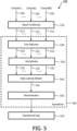
- FIG. 5 is a schematic diagram of an ultrasound imaging system 500 implementing deep learning-based beamforming, according to embodiments of the present disclosure.
- the system 500 is substantially similar to the system 100, but utilizes a deep learning-based beamformer 560 instead of the DAS-based beamformer 114 for beamforming.
- the system 500 includes a signal conditioning component 510 and the deep learning-based beamformer 560.
- the signal conditioning component 510 and the deep learning-based beamformer 560 can be implemented by a combination of hardware and software.
- the deep learning-based beamformer 560 includes a time-alignment component 520, a normalization component 530, a deep learning network 540, and a de-normalization component 550.
- the system 500 may include a transducer array (e.g., the transducer 112).
- the transducer array may include M number of acoustic elements (e.g., the acoustic elements 202) that can be configured to transmit ultrasound energy into an anatomy (e.g., the anatomical object 105) and receive ultrasound echoes reflected from the anatomy back to the transducer array.
- the ultrasound echoes may be received in the form of M number of channels, each carrying an ultrasound echo channel signal 502 (e.g., the digital ultrasound echo channel signals 162).
- the ultrasound echo channel signals 502 may be raw radio frequency (RF) channel signals.
- the ultrasound echo channel signals 502 may be referred to as per-channel ultrasound RF echo data.
- the signal conditioning component 510 can include one or more filters configured to receive the ultrasound echo channel signals 502 and condition the received ultrasound echo channel signals 502 prior to beamforming.
- the signal conditioning component 510 may apply a bandpass filter to the ultrasound echo channel signals 502 to remove electronic noise.
- the bandpass filter may span all quadrature band pass filters (QBPs) that are used by the system 500 for subsequent frequency compounding during image reconstruction.
- QBPs quadrature band pass filters
- the transducer array may generate ultrasound beams at a center frequency of about 2.4 MHz and the ultrasound echo channel signals 502 are sampled at about 32 MHz (e.g., by ADCs such as the 204).
- the ultrasound echo channel signals 502 can be decimated at about 8 MHz to reduce subsequent computational speed requirements.
- the normalization component 530 is coupled to the time-alignment component 520.
- the normalization component 530 is configured to normalize the signal levels of the time-aligned per-channel ultrasound echo signals 522 by scaling signal levels or amplitudes of the time-aligned per-channel ultrasound echo signals 522 by the local energy of the signals 522.
- the normalization component 530 performs the signal level normalization in subsets of samples from the time-aligned per-channel ultrasound echo signals 522, as described in greater detail herein.
- the deep learning network 540 is coupled to the normalization component 530.
- the deep learning network 540 maps the normalized, time-aligned per-channel ultrasound echo signals 532 to normalized beamformed data 542.
- the deep learning network 540 can be a CNN network. Configurations or architectures of the deep learning network 540 and/or training of the deep learning network 540 are described in greater detail herein.
- the applying of the deep learning network 540 to the normalized, time-aligned per-channel ultrasound echo channel signals 532 can reduce the complexity of the deep learning network 540 and improve the beamforming or beam-summing prediction performance of the deep learning network.
- the performing of the time-alignment or time-delaying prior to the deep learning network 540 can allow the deep learning network 540 to be trained to learn beamforming without having to learn the time-alignment.
- the time-alignment or time-delay operations have relatively low computational complexity, and thus can be performed outside of the deep learning network 540 without a high computational cost.
- the normalization prior to the deep learning network 540 can avoid having samples with large amplitudes or signal levels dominate samples with lower amplitudes or signal levels.
- the deep learning network 540 can be trained to learn the summing operations in beamforming, and not amplitude mapping. As such, the normalization can prevent numerical imbalance in the loss function of the deep learning network 540.
- the loss function is a measure of how well the deep learning network 540 performs and is used as an error measure during training as described in greater detail herein.
- the denormalization component 550 is coupled to the deep learning network 540.
- the denormalization component 550 is configured to de-normalize the beamformed data 542 based on the normalization performed at the normalization component 530. In other words, the de-normalization component 550 reverses the operations of the normalization component 530 as described in greater detail herein.
- the de-normalization component 550 produces de-normalized beamformed data 552.
- the beamformed data 552 can be further processed by the processor circuit 116 and/or the processor circuit 134, for exampling, including frequency compounding, envelope detection, logarithmic compression, and/or non-linear image filtering as described above with respect to FIG. 1 , to produce an image.
- the deep learning network 540 is trained such that the beamformed data 552 has a higher image quality or resolution than the DAS-based beamformed data 230.
- images generated from the beamformed data 552 can have a higher image quality or resolution than images generated from the DAS-based beamformed data 230.
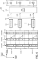
- FIG. 6 is a schematic diagram illustrating a normalization scheme 600 for deep learning-based beamforming, according to aspects of the present disclosure.
- the scheme 600 is implemented by the normalization component 530 of FIG. 5 .
- the scheme 600 applies normalization to the M channels of time-aligned ultrasound echo channel signals 522.
- Each ultrasound echo channel signal 522 in a receive channel includes a plurality of time samples along an imaging depth (e.g., in a y-dimension). The time samples are shown as symbols "X" in FIG. 6 .
- the scheme 600 partitions the samples in ultrasound echo channel signals 522 into multiple subsets 610 based on an imaging depth. For simplicity of discussion and illustration, three subsets 610a, 610b, and 610c are shown, each corresponding to an imaging depth range. However, the number of subsets 610 may vary depending on the embodiments. In some examples, the imaging depth range for each subset may correspond to about four times the wavelength (e.g., 4 ⁇ ) of a corresponding ultrasound transmission beam.
- the normalization component 530 normalizes each subset 610 by scaling the signal levels or amplitudes of the samples in the corresponding subset 610 based on the signal energy of the corresponding subset 610.
- the normalization component 530 produces a subset of samples in the normalized ultrasound echo channel signals 532 from each subset 610.
- the subset 610a is normalized to produce a subset 620a of the samples in the normalized ultrasound echo channel signals 532
- the subset 610b is normalized to produce a subset 620b of samples in the normalized ultrasound echo channel signals 532
- the subset 610c is normalized to produce a subset 620c of samples in the normalized ultrasound echo channel signals 532.
- the normalized ultrasound echo channel signals 532 may include signal levels between about 1 and -1.
- the deep learning network 540 is applied to the normalized ultrasound echo channel signals 532 to produce the beamformed data 542.
- the deep learning network 540 outputs a beamformed output sample or pixel 632a for the subset 610a, a beamformed output sample or pixel 632b for the subset 610b, and a beamformed output sample or pixel 632c for the subset 610c.
- the pixel 632a corresponds to a center time sample 612a of the subset 610a.
- the pixel 632b corresponds to a center time sample 612b of the subset 610b.
- the pixel 632c corresponds to a center time sample 612c of the subset 610c.
- the subset 610a includes about 13 samples for each channel along the imaging depths.
- the sample 612a may correspond to the 7 th sample in the Channel(i).
- the time sample 612a and the beamformed output pixel 632a may correspond to the same pixel location in the final image.
- the time sample 612b and the beamformed output pixel 632b may correspond to the same pixel location in the final image.
- the time sample 612c and the beamformed output pixel 632c may correspond to the same pixel location in the final image.
- the normalization component 530 performs the scaling by dividing the subset of samples by the root-mean-square (RMS) of the signal level of a sample corresponding to a beamform output sample or pixel. For example, the normalization component 530 scales the sample 612a by dividing the sample 612a with the RMS of all the samples in subset 610a, scales the sample 612b by dividing the sample 612b with the RMS of all the samples in subset 610b, and scales the sample 612c by dividing the sample 612c with the RMS of all the samples in subset 610c. Accordingly, each sample 612a, 612b, or 612c is sampled with respect to the signal energy in its neighborhood.
- the normalized echo channel signals 532 may mostly include samples with a signal energy between about 0 and about 1.
- a normalization value (e.g., RMS) is calculated from all the samples in the corresponding subset and the sample (e.g., the sample 612a) located in the center of the subset is divided by the normalization value.
- the denormalization may be performed using similar sliding window mechanisms. Thus, after applying the sliding windows to the normalization and the denormalization, all samples for the final beamformed data 552 are calculated.
- the deep learning network 540 is trained to map per-channel ultrasound echo data acquired from a transducer of a certain aperture size (e.g., the aperture size 206) or including a certain number of acoustic elements (e.g., the acoustic elements 202) to beamformed data corresponding to beamformed data obtained from a larger transducer aperture size (e.g., about double) or a greater number of acoustic elements.
- the beamformed data 552 predicted by the deep learning network 540 has a higher image quality (e.g., higher resolution and/or reduced clutters or artefacts) than what the transducer in use can provide.
- the 3D dataset is partitioned into 3D data subsets based on imaging depths
- the normalization component 530 may scale a center sample in each 3D data subset by dividing the centered sample with the RMS of all samples in the corresponding 3D subset
- the deep learning network 540 maps each 3D data subset to a beamformed output sample or pixel.
- the ultrasound beams are focused beams (e.g., the focused ultrasound transmission beams 320). In some other examples, the ultrasound beams are unfocused beams or diverging beams (e.g., the unfocused ultrasound transmission beams 420).
- the target data 1012 may correspond to beamformed data generated from the ultrasound channel data 1002 using a DAS-based beamformer (e.g., the beamformer 114).
- the target data 1012 is also normalized so that the training does not have to learn amplitude mapping.
- the deep learning network 540 can be applied to the ultrasound channel data 1002 using forward propagation to produce an output 1004 (e.g., the beamformed data 542).
- the coefficients of the filters 722 in the convolutional layers 720 and the weightings in the fully connected layers 730 can be adjusted using backward propagation to minimize the error between the output 1004 and the target output 1012.
- the error function may be a MSE function or any other suitable error measure function.
- the scheme 1000 trains the deep learning network 540 to approximate the beamforming provided by the beamformer 114.
- the training or the adjusting of the coefficients for the filters 722 may be repeated for multiple input-output pairs.
- the first stage 1010 functions as an initialization of filter coefficients and/or weights in the deep learning network 540.
- the scheme 1000 uses the filter coefficients and/or weights obtained for the deep learning network 540 from the first stage 1010 as a start and continues with the training.
- the scheme 1000 trains the deep learning network 540 using an input-output pair, where the input includes ultrasound channel data 1002 and the output includes target beamformed data 1022.
- the target data 1022 may correspond to beamformed data of the same subjected generated from ultrasound echo channel signals collected from a greater number of transmit events, for example, m ⁇ T number of transmit events or triggers, where m is greater than 1.
- the target data 1022 is normalized data.
- the target data 1022 may be generated from 5 transmit events (e.g., with 5 repeated ultrasound transmissions) and the target data 1022 may be generated from 51 transmit events.
- the deep learning network 540 is trained by applying the ultrasound channel data 1002 using forward propagation to produce an output 1006 (e.g., the beamformed data 542).
- the coefficients of the filters 722 in the convolutional layers 720 and the weightings in the fully connected layers 730 can be adjusted using backward propagation to minimize the error between the output 1006 and the target output 1022.
- the training or the adjusting of the coefficients for the filters 722 may be repeated for multiple input-output pairs. While the scheme 1000 utilizes two stages of training, in some embodiments, the scheme 1000 may perform the second stage 1020 of training without performing the first stage 1010 of the training.
- the scheme 1000 trains the deep learning network 540 to map per-channel ultrasound echo signals to beamformed data corresponding to a greater number of transmit events. Accordingly, the deep learning network 540 can provide a higher image quality than a conventional DAS-based beamformer (e.g., the beamformer 114). Further, when using diverging beams for unfocused imaging, the scheme 1000 can train the deep learning network 540 to compensate for artefacts caused by the use of diverging beams and improve the final ultrasound image quality without a significant increase in acquisition time.
- a conventional DAS-based beamformer e.g., the beamformer 114
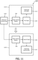
- FIG. 11 is a schematic diagram illustrating a deep learning network training scheme 1100, according to aspects of the present disclosure.
- the scheme 1100 can be implemented by a computer system such as the host 130.
- the scheme 1100 can be employed to train the deep learning network 540 or the CNN 710 for ultrasound beamforming.
- the scheme 1100 trains the deep learning network 540 in two stages 1110 and 1120.
- the scheme 1100 trains the deep learning network 540 using an input-output pair, where the input includes ultrasound channel data 1102 and the output includes target beamformed data 1112.
- the ultrasound channel data 1102 may be normalized, time-aligned ultrasound echo channel signals similar to the normalized, time-aligned ultrasound echo channel signals 532.
- the ultrasound channel data 1102 may be acquired from a patient during a clinical setting or from a phantom in a test setup.
- the ultrasound channel data 1102 can be a 2D dataset with an x-dimension corresponding to receive channels and a y-dimension corresponding to imaging depths.
- the target data 1112 may correspond to beamformed data of the same subjected generated from the ultrasound channel data 1102 using a DAS-based beamformer (e.g., the beamformer 114).
- the target data 1112 may have a first SNR (e.g., S decibels (dB)).
- the target data 1112 is also normalized so that the training does not have to learn amplitude mapping.
- the deep learning network 540 can be applied to the ultrasound channel data 1102 using forward propagation to produce an output 1104 (e.g., the beamformed data 542).
- the coefficients of the filters 722 in the convolutional layers 720 and the weightings in the fully connected layers 730 can be adjusted using backward propagation to minimize the error between the output 1104 and the target output 1112.
- the error function may be a MSE function or any other suitable error measure function.
- the scheme 1100 trains the deep learning network 540 to approximate the beamforming provided by the beamformer 114.
- the training or the adjusting of the coefficients for the filters 722 may be repeated for multiple input-output pairs.
- the first stage 1110 functions as an initialization of filter coefficients and/or weights in the deep learning network 540
- the scheme 1100 uses the filter coefficients and/or weights obtained for the deep learning network 540 from the first stage 1110 as a start and continues with the training.
- the scheme 1100 trains the deep learning network 540 using an input-output pair, where the input includes ultrasound channel data 1102 and the output includes target beamformed data 1122.
- the target data 1122 may correspond to beamformed data of the same subject, but with a second SNR higher than the first SNR (e.g., n ⁇ S dB, where n is greater than 1).
- the higher SNR can be due to the use of more advance signal and/or imaging processing techniques, a larger transducer aperture size, and/or a greater number of transmit firings.
- the target data 1122 is normalized data.
- the deep learning network 540 is trained by applying the ultrasound channel data 1102 using forward propagation to produce an output 1106 (e.g., the beamformed data 542).
- the coefficients of the filters 722 in the convolutional layers 720 and the weightings in the fully connected layers 730 can be adjusted using backward propagation to minimize the error between the output 1106 and the target output 1122.
- the training or the adjusting of the coefficients for the filters 722 may be repeated for multiple input-output pairs. While the scheme 1100 utilizes two stages of training, in some embodiments, the scheme 1100 may perform the second stage 1120 of training without performing the first stage 1110 of the training.
- the scheme 1100 trains the deep learning network 540 to map per-channel ultrasound echo signals to beamformed data corresponding to a higher SNR than beamformed data from a conventional DAS-based beamformer (e.g., the beamformer 114).
- a conventional DAS-based beamformer e.g., the beamformer 114.
- FIG. 12 illustrates ultrasound images generated from DAS-based beamforming and deep learning-based beamforming, according to aspects of the present disclosure.
- the ultrasound images 1210, 1220, and 1230 are acquired from in-vivo scan of a patient's heart. Initially, a first set of per-channel ultrasound echo signals (e.g., the digital ultrasound channel echo signals 162 and 502 and the ultrasound channel data 702 and 802) is collected after 5 transmit triggers of unfocused ultrasound beams or diverging beams (e.g., the unfocused ultrasound beam 420). Subsequently, a second set of per-channel ultrasound echo signals is collected after 51 transmit triggers of unfocused ultrasound beams or diverging beams.
- a first set of per-channel ultrasound echo signals e.g., the digital ultrasound channel echo signals 162 and 502 and the ultrasound channel data 702 and 802
- a second set of per-channel ultrasound echo signals is collected after 51 transmit triggers of unfocused ultrasound beams or diverging beams.
- the ultrasound image 1210 is generated using a DAS-based beamformer (e.g., the beamformer 114) to beamform the second set of per-channel ultrasound echo signals from the 51 transmit triggers.
- the image 1220 is generated using the DAS beamformer to beamform the first set of per-channel ultrasound echo signals from the 5 transmit triggers.
- the image 1230 is generated by applying the deep learning network 540 to map the first set of per-channel ultrasound echo signals with the 5 transmit triggers to beamformed data (e.g., the beamformed data 542 and 704) from the 51 transmit triggers.
- the image 1210 from the 51 transmit triggers provides a higher image quality (e.g., better contrast, better contrast-to-noise) than the image 1220 from the 5 transmit triggers as expected.
- the deep learning-based beamformed image 1230 from the 5 transmit triggers provides an image quality or resolution comparable to the DAS-based beamformed image 1210 from the 51 transmits triggers.
- the amount of clutters or artefacts in the image 1230 generated from the deep learning-based beamforming is significantly less than the image 1220 generated from the DAS-based beamforming with the same number of transmit triggers. Accordingly, deep learning-based beamforming can provide a higher image quality or resolution than conventional DAS-based beamforming.
- the schemes 800, 1000, and 1100 can use any suitable combination of simulation data generated offline, data acquired from a patient in a clinical setting, and data acquired from a phantom in a test setup to train the deep learning network 540.
- the schemes 800, 1000, and 1100 can train the deep learning network 540 to output beamformed data with a higher SNR.
- the deep learning network 540 can be trained to suppress clutters from noise sources, such as acoustic noise, thermal noise, electronic noise, aberration, and/or reverberation, that are introduced due to poor acoustic conditions and cannot be addressed along the signal paths of the ultrasound system (e.g., the systems 100, 200, and/or 500).
- noise sources such as acoustic noise, thermal noise, electronic noise, aberration, and/or reverberation
- the deep learning network 540 can be trained to learn mapping of micro-beamformed data instead of per-channel ultrasound echo data to beamformed data.
- a system e.g., the systems 100 and 200
- the system may have 80 receive channels.
- the system may include micro-beamformers for micro-beamforming.
- the system may group four adjacent acoustic elements (e.g., the acoustic elements 202) together and apply a beamformer to the group of acoustic elements to focus and steer delays to corresponding receive channels such that the micro-beamformed points are along the main axis of the transmit beam.
- the 80 receive channels are reduced to 20 channels.
- the deep learning network 540 can be trained and applied to map the 20 micro-beamformed channel signals to beamformed data (e.g., the beamformed data 542) using substantially similar mechanisms as described above.
- the error functions or loss functions in the schemes 800, 1000, and 1100 described above are error or cost functions between the ground truth pixel values (e.g., in the target data 812, 822, 1012, 1022, 1112, and 1122) and the deep learning network 540 predicted pixel values (e.g., in the outputs 804, 806, 1004, 1006, 1104, and 1006), the deep learning network 540 can be trained to predict other signal values at an earlier stage (e.g., prior to beamforming) in the signal path of the ultrasound systems 100 and/or 200.
- the deep learning network 540 can be trained to learn mapping transmit compounding from a limited number of transmits to an increased number of transmits.
- the loss function for the deep learning network 540 may be the difference between the ground truth transmit compounded channel data and network predicted compounded channel data corresponding to a greater number of transmits.
- the input to the deep learning network 540 may be a 3D ultrasound echo channel dataset as described above, where with the x-dimension may correspond to receive channels, the y-dimension may correspond to imaging depths, and the z-dimension correspond to transmit events (e.g., T).
- the deep learning network 540 can be trained to output a compounded echo channel dataset corresponding to m ⁇ T transmits, where m greater than 1.
- the 3D ultrasound echo channel dataset can be converted to a 2D dataset by summing the per-channel ultrasound echo signals from the T transmit events (e.g., collapsed in the transmit or z-dimension) and the deep learning network 540 can be trained to provide the same compounded echo channel dataset corresponding to m ⁇ T transmits.
- the deep learning network 540 can output the compounded channel data or beamformed data in any suitable dimension or representations and the loss function can be modified accordingly.
- the deep learning network 540 can be trained to provide a 1D compounded channel data collapsed in the transmit or z-dimension and sampled at the depth or y-dimension.
- the deep learning network 540 can be trained to provide a 1D DAS vector collapsed in the channel or x-dimension and sampled in the depth or y-dimension or the scalar value of the corresponding pixel point collapsed in the channel or x-dimension and the transmit or z-dimension and sampled in the depth or y-dimension.
- While the input data in the schemes 800, 1000, and 1100 described above is a 3D matrix for each pixel, a 3D matrix of aligned data for each beam may be used as input.
- the fully convolutional architecture may operate on the larger dataset using substantially similar mechanisms as described above.
- Instructions 1366 may also be referred to as code.
- the terms "instructions” and “code” should be interpreted broadly to include any type of computer-readable statement(s).
- the terms “instructions” and “code” may refer to one or more programs, routines, sub-routines, functions, procedures, etc.
- “Instructions” and “code” may include a single computer-readable statement or many computer-readable statements.
- the memory 1364 may correspond to the memory 138 of FIG. 1 .
- the communication module 1368 can include any electronic circuitry and/or logic circuitry to facilitate direct or indirect communication of data between the processor circuit 1300, the probe 110, and/or the display 132.
- the communication module 1368 can be an input/output (I/O) device.
- the communication module 1368 facilitates direct or indirect communication between various elements of the processor circuit 1300 and/or the host 130 ( FIG. 1 ).
- the communication module 1368 may correspond to the communication interface 118 ( FIG. 1 ).
- the communication module 1368 may correspond to the communication interface 136 ( FIG. 1 ).
- the method 1400 includes generating beamformed data by applying a predictive network (e.g., the deep learning network 540) to the normalized ultrasound channel data (e.g., the ultrasound echo channel signals 532).
- a predictive network e.g., the deep learning network 540
- the normalized ultrasound channel data e.g., the ultrasound echo channel signals 5302.
- the method 1400 includes de-normalizing the beamformed data by applying a second scaling function to the beamformed data based on the signal levels of the ultrasound channel data, for example, utilizing the denormalization component 550.
- the method 1400 includes generating an image of the anatomy from the beamformed data.
- the normalization can include selecting a subset (e.g., the subset 610a, 610b, or 610c) of the plurality of samples based on an imaging depth and scaling a first signal level of a first sample (e.g., the sample 612a, 612b, or 612c) of the subset of the plurality of samples based on second signal levels (e.g., RMS) of the plurality of samples to produce a subset of the normalized ultrasound channel data (e.g., the subset 620a, 620b, or 620c).
- the first sample corresponds to a pixel location in the image.
- the generating the beamformed data includes applying the predictive network to the subset of the normalized ultrasound channel data to produce a first output value of the plurality of output values in the beamformed data, where the first output value correspond to the same pixel location in the image as the first sample.
- the ultrasound channel data is associated with a first SNR and the beamformed data is associated with a second SNR greater than the first SNR.
- the prediction network is trained using the scheme 1100.
- the use of normalized, time-aligned ultrasound echo channel signals as inputs to the deep learning network allows the deep learning network to be trained for beamforming or beam-summing without having to learn amplitude mapping and/or time-delay mapping, and thus reduces the complexity of the network. Further, the use of the deep learning network can provide a computational cost advantage compared to conventional DAS-based beamformer (e.g., the beamformer 114) since operations in the inference stage of the deep learning network are mostly convolutions (e.g., multiply-adds) and matrix multiplications.
Landscapes
- Engineering & Computer Science (AREA)
- Physics & Mathematics (AREA)
- Health & Medical Sciences (AREA)
- Theoretical Computer Science (AREA)
- General Physics & Mathematics (AREA)
- Life Sciences & Earth Sciences (AREA)
- General Health & Medical Sciences (AREA)
- Remote Sensing (AREA)
- Radar, Positioning & Navigation (AREA)
- Biomedical Technology (AREA)
- Biophysics (AREA)
- Molecular Biology (AREA)
- Software Systems (AREA)
- Computing Systems (AREA)
- Mathematical Physics (AREA)
- Evolutionary Computation (AREA)
- Data Mining & Analysis (AREA)
- General Engineering & Computer Science (AREA)
- Artificial Intelligence (AREA)
- Computational Linguistics (AREA)
- Acoustics & Sound (AREA)
- Computer Networks & Wireless Communication (AREA)
- Medical Informatics (AREA)
- Computer Vision & Pattern Recognition (AREA)
- Radiology & Medical Imaging (AREA)
- Nuclear Medicine, Radiotherapy & Molecular Imaging (AREA)
- Quality & Reliability (AREA)
- Pathology (AREA)
- Heart & Thoracic Surgery (AREA)
- Surgery (AREA)
- Animal Behavior & Ethology (AREA)
- Public Health (AREA)
- Veterinary Medicine (AREA)
- Multimedia (AREA)
- Ultra Sonic Daignosis Equipment (AREA)
Claims (15)
- Ultraschallbildgebungssystem (500), umfassend:eine Anordnung (112) akustischer Elemente, die dazu konfiguriert sind, Ultraschallenergie in eine Anatomie zu übertragen und mit der Anatomie verbundene Ultraschallechos zu empfangen; undeine Prozessorschaltung (1300), die mit der Anordnung akustischer Elemente in Kommunikation steht und zu Folgendem konfiguriert ist:Empfangen (1410) von der Anordnung von Ultraschallkanaldaten (502, 702), die den empfangenen Ultraschallechos entsprechen;zeitliches Ausrichten (520) der Ultraschallkanaldaten;Normalisieren (1420, 530) der zeitlich ausgerichteten Ultraschallkanaldaten (522) durch Anwenden einer ersten Skalierungsfunktion auf die zeitlich ausgerichteten Ultraschallkanaldaten basierend auf Signalpegeln der zeitlich ausgerichteten Ultraschallkanaldaten;Erzeugen (1430) von strahlgeformten Daten (542, 704) durch Anwenden eines prädiktiven Netzwerks (540, 700) auf die normalisierten zeitlich ausgerichteten Ultraschallkanaldaten (532);Denormalisieren (1440, 550) der strahlgeformten Daten durch Anwenden einer zweiten Skalierungsfunktion auf die strahlgeformten Daten basierend auf den Signalpegeln der Ultraschallkanaldaten;Erzeugen (1450) eines Bildes (910, 920, 1230) der Anatomie aus den strahlgeformten Daten; undAusgeben des Bildes der Anatomie an ein Display, das mit der Prozessorschaltung in Kommunikation steht,dadurch gekennzeichnet, dass das prädiktive Netzwerk (540, 700) so konfiguriert ist, dass es die Summierungsvorgänge beim Strahlformen der normalisierten Ultraschallkanaldaten (532) durchführt.
- System nach Anspruch 1, wobei die Prozessorschaltung weiter für Folgendes konfiguriert ist:
Anwenden von Zeitverzögerungen auf die normalisierten Ultraschallkanaldaten basierend auf einer Bildgebungstiefe. - System nach Anspruch 1,wobei die Ultraschallkanaldaten eine Vielzahl von Proben für eine Vielzahl von Kanälen einschließen,wobei die strahlgeformten Daten eine Vielzahl von Ausgabewerten einschließen, wobei die Prozessorschaltung weiter dazu konfiguriert ist, basierend auf einer Bildgebungstiefe eine Teilmenge (610) der Vielzahl von Proben auszuwählen,wobei die Prozessorschaltung, die die Ultraschallkanaldaten normalisiert, Skalieren eines ersten Signalpegels einer ersten Probe der Teilmenge der Vielzahl von Proben basierend auf zweiten Signalpegeln der Teilmenge der Vielzahl von Proben einschließt, um eine Teilmenge der normalisierten Ultraschallkanaldaten zu erzeugen, undwobei die Prozessorschaltung, die die strahlgeformten Daten erzeugt, Anwenden des prädiktiven Netzwerks auf die Teilmenge der normalisierten Ultraschallkanaldaten einschließt, um einen ersten Ausgabewert der Vielzahl von Ausgabewerten in den strahlgeformten Daten zu erzeugen.
- System nach Anspruch 3, wobei die erste Probe und der erste Ausgabewert einer gleichen Pixelposition im Bild entsprechen und
wobei die Prozessorschaltung, die die Ultraschallkanaldaten normalisiert, optional Skalieren des ersten Signalpegels der ersten Probe basierend auf einem quadratischen Mittelwert (RMS) der Teilmenge der Vielzahl von Proben einschließt. - System nach Anspruch 1, wobei die Anordnung akustischer Elemente eine erste Blendengröße einschließt, und wobei die strahlgeformten Daten mit einer zweiten Blendengröße verbunden sind, die größer als die erste Blendengröße ist.
- System nach Anspruch 5, wobei das prädiktive Netzwerk trainiert wird durch:Bereitstellen von Test-Ultraschallkanaldaten, die basierend auf der ersten Blendengröße erzeugt wurden, und von ersten zielstrahlgeformten Daten, die basierend auf der zweiten Blendengröße erzeugt wurden; undTrainieren des prädiktiven Netzwerks, um die ersten zielstrahlgeformten Daten aus den Test-Ultraschallkanaldaten zu erzeugen.
- System nach Anspruch 6, wobei das prädiktive Netzwerk trainiert wird durch:
Bereitstellen von zweiten zielstrahlgeformten Daten, die basierend auf der ersten Blendengröße erzeugt wurden; und Trainieren des prädikativen Netzwerks zum Erzeugen der zweiten zielstrahlgeformten Daten aus den Test-Ultraschallkanaldaten vor Trainieren des prädikativen Netzwerks zum Erzeugen der ersten zielstrahlgeformten Daten. - System nach Anspruch 1, wobei die Ultraschallkanaldaten aus einer ersten Menge von Ultraschall-Sendeauslöseereignissen erzeugt wurden, und wobei die strahlgeformten Daten mit einer zweiten Menge von Ultraschall-Sendeauslöseereignissen verbunden sind, die größer ist als die erste Menge von Ultraschall-Sendeauslöseereignissen.
- System nach Anspruch 8, wobei das prädiktive Netzwerk trainiert wird durch:Bereitstellen von Test-Ultraschallkanaldaten, die basierend auf der ersten Menge von Ultraschall-Sendeauslöseereignissen erzeugt wurden, und von ersten zielstrahlgeformten Daten, die basierend auf der zweiten Menge von Ultraschall-Sendeauslöseereignissen erzeugt wurden; undTrainieren des prädiktiven Netzwerks, um die ersten zielstrahlgeformten Daten aus den Test-Ultraschallkanaldaten zu erzeugen.
- System nach Anspruch 9, wobei das prädiktive Netzwerk trainiert wird durch:Bereitstellen von zweiten zielstrahlgeformten Daten, die basierend auf der ersten Menge von Ultraschall-Sendeauslöseereignissen erzeugt wurden; undTrainieren des prädiktiven Netzwerks zum Erzeugen der zweiten zielstrahlgeformten Daten aus den Test-Ultraschallkanaldaten vor Trainieren des prädiktiven Netzwerks zum Erzeugen der ersten zielstrahlgeformten Daten.
- System nach Anspruch 1, wobei die Ultraschallkanaldaten mit einem ersten Signal-Rausch-Verhältnis (SNR) verbunden sind und wobei die strahlgeformten Daten mit einem zweiten SNR verbunden sind, das größer als das erste SNR ist.
- System nach Anspruch 1, wobei die Anordnung akustischer Elemente eine eindimensionale Anordnung akustischer Elemente einschließt.
- System nach Anspruch 1, wobei die Anordnung akustischer Elemente eine zweidimensionale Anordnung akustischer Elemente einschließt.
- Ultraschallbildgebungsverfahren (1400), umfassend:Empfangen (1410) von Ultraschallkanaldaten (502, 702), die mit einer Anatomie verbundenen Ultraschallechos entsprechen, an einer Prozessorschaltung (1300), die mit einer Anordnung (112) akustischer Elemente in Kommunikation steht;zeitliches Ausrichten (520) der Ultraschallkanaldaten;Normalisieren (1420, 530) der zeitlich ausgerichteten Ultraschallkanaldaten (522) durch Anwenden einer ersten Skalierungsfunktion auf die zeitlich ausgerichteten Ultraschallkanaldaten basierend auf Signalpegeln der zeitlich ausgerichteten Ultraschallkanaldaten;Erzeugen (1430) von strahlgeformten Daten (542, 704) durch Anwenden eines prädiktiven Netzwerks (540, 700) auf die normalisierten zeitlich ausgerichteten Ultraschallkanaldaten (532);Denormalisieren (1440, 550) der strahlgeformten Daten durch Anwenden einer zweiten Skalierungsfunktion auf die strahlgeformten Daten basierend auf den Signalpegeln der Ultraschallkanaldaten;Erzeugen eines Bildes (910, 920, 1230) der Anatomie aus den strahlgeformten Daten; undAusgeben des Bildes der Anatomie an ein Display, das mit der Prozessorschaltung in Kommunikation steht,dadurch gekennzeichnet, dass das prädiktive Netzwerk (540, 700) so konfiguriert ist, dass es die Summierungsvorgänge beim Strahlformen der normalisierten Ultraschallkanaldaten (532) durchführt.
- Nicht flüchtiges computerlesbares Medium, das computerlesbare Anweisungen speichert, die, wenn sie von der Prozessorschaltung eines Ultraschallbildgebungssystems nach einem der Ansprüche 1 bis 13 ausgeführt werden, bewirken, dass die Prozessorschaltung die Schritte des Verfahrens nach Anspruch 14 durchführt.
Applications Claiming Priority (2)
| Application Number | Priority Date | Filing Date | Title |
|---|---|---|---|
| US201962809080P | 2019-02-22 | 2019-02-22 | |
| PCT/EP2020/053288 WO2020169384A1 (en) | 2019-02-22 | 2020-02-10 | Ultrasound imaging with deep learning-based beamforming and associated devices, systems, and methods |
Publications (2)
| Publication Number | Publication Date |
|---|---|
| EP3928121A1 EP3928121A1 (de) | 2021-12-29 |
| EP3928121B1 true EP3928121B1 (de) | 2025-07-02 |
Family
ID=69570659
Family Applications (1)
| Application Number | Title | Priority Date | Filing Date |
|---|---|---|---|
| EP20704830.7A Active EP3928121B1 (de) | 2019-02-22 | 2020-02-10 | Ultraschallbildgebung mit deep-learning basierter strahlformung sowie zugehörige vorrichtungen, systeme und verfahren |
Country Status (4)
| Country | Link |
|---|---|
| US (1) | US11950960B2 (de) |
| EP (1) | EP3928121B1 (de) |
| CN (1) | CN113454484B (de) |
| WO (1) | WO2020169384A1 (de) |
Families Citing this family (7)
| Publication number | Priority date | Publication date | Assignee | Title |
|---|---|---|---|---|
| CN114554969A (zh) * | 2019-10-16 | 2022-05-27 | 皇家飞利浦有限公司 | 用于基于深度学习的超声波束形成的方法和装置 |
| US20210353249A1 (en) * | 2020-05-12 | 2021-11-18 | Acoustiic Inc. | Detection and treatment of tumors using ultrasound |
| US11710218B2 (en) * | 2021-03-17 | 2023-07-25 | GE Precision Healthcare LLC | System and method for normalizing dynamic range of data acquired utilizing medical imaging |
| US12551193B2 (en) * | 2022-02-07 | 2026-02-17 | Canon Medical Systems Corporation | Ultrasound diagnosis apparatus |
| US20240385318A1 (en) * | 2023-05-19 | 2024-11-21 | Robert Bosch Gmbh | Machine-learning based object detection and localization using ultrasonic sensor data |
| AU2024355499A1 (en) * | 2023-10-05 | 2026-04-09 | University Of Leeds | Volumetric ultrasound imaging |
| US12572465B2 (en) * | 2024-09-05 | 2026-03-10 | SanDisk Technologies, Inc. | Data storage device and method for buffer occupancy-based data placement to avoid video loss |
Family Cites Families (18)
| Publication number | Priority date | Publication date | Assignee | Title |
|---|---|---|---|---|
| US5997479A (en) * | 1998-05-28 | 1999-12-07 | Hewlett-Packard Company | Phased array acoustic systems with intra-group processors |
| US6468216B1 (en) * | 2000-08-24 | 2002-10-22 | Kininklijke Philips Electronics N.V. | Ultrasonic diagnostic imaging of the coronary arteries |
| FR2886533B1 (fr) * | 2005-06-03 | 2007-09-14 | Theraclion Soc Par Actions Sim | Tete d'imagerie et de traitement d'organes d'etres vivants et procede de fabrication |
| FR2886534A1 (fr) * | 2005-06-03 | 2006-12-08 | Theraclion Soc Par Actions Sim | Tete d'imagerie et de traitement d'organes d'etres vivants et procede de fabrication |
| US8565856B2 (en) * | 2007-09-18 | 2013-10-22 | Siemens Medical Solutions Usa, Inc. | Ultrasonic imager for motion measurement in multi-modality emission imaging |
| US8348846B2 (en) * | 2008-09-30 | 2013-01-08 | Mediri Gmbh | 3D motion detection and correction by object tracking in ultrasound images |
| WO2010046803A1 (en) * | 2008-10-20 | 2010-04-29 | Koninklijke Philips Electronics, N.V. | Low voltage ultrasound system with high voltage transducers |
| US10542962B2 (en) * | 2009-07-10 | 2020-01-28 | Elekta, LTD | Adaptive radiotherapy treatment using ultrasound |
| CN103153196B (zh) * | 2011-09-22 | 2016-10-26 | 东芝医疗系统株式会社 | 超声波诊断装置 |
| AU2012322020A1 (en) * | 2011-10-12 | 2014-05-29 | Seno Medical Instruments, Inc. | System and method for acquiring optoacoustic data and producing parametric maps thereof |
| KR102617888B1 (ko) * | 2014-08-18 | 2023-12-22 | 마우이 이미징, 인코포레이티드 | 네트워크-기반 초음파 이미징 시스템 |
| US10835210B2 (en) * | 2015-03-30 | 2020-11-17 | Siemens Medical Solutions Usa, Inc. | Three-dimensional volume of interest in ultrasound imaging |
| US12383236B2 (en) * | 2016-10-19 | 2025-08-12 | Koninklijke Philips N.V. | Ultrasound system with deep learning network providing real time image identification |
| CN110800019B (zh) * | 2017-06-22 | 2024-02-06 | 皇家飞利浦有限公司 | 用于复合超声图像生成的方法和系统 |
| CN110785126B (zh) * | 2017-06-23 | 2022-09-27 | 梅约医学教育与研究基金会 | 用于超声系统独立衰减系数估计的方法 |
| EP3435324A1 (de) * | 2017-07-27 | 2019-01-30 | Koninklijke Philips N.V. | Verarbeitung eines fötalen ultraschallbildes |
| US11602330B2 (en) * | 2017-12-12 | 2023-03-14 | Oncoustics Inc. | Machine learning to extract quantitative biomarkers from RF spectrums |
| EP3553785A1 (de) * | 2018-04-11 | 2019-10-16 | Koninklijke Philips N.V. | Systeme und verfahren zur erzeugung verbesserter diagnostischer bilder aus daten medizinischer 3d-bilder |
-
2020
- 2020-02-10 EP EP20704830.7A patent/EP3928121B1/de active Active
- 2020-02-10 US US17/423,872 patent/US11950960B2/en active Active
- 2020-02-10 CN CN202080015904.5A patent/CN113454484B/zh active Active
- 2020-02-10 WO PCT/EP2020/053288 patent/WO2020169384A1/en not_active Ceased
Also Published As
| Publication number | Publication date |
|---|---|
| CN113454484B (zh) | 2025-10-14 |
| US11950960B2 (en) | 2024-04-09 |
| WO2020169384A1 (en) | 2020-08-27 |
| US20220096054A1 (en) | 2022-03-31 |
| CN113454484A (zh) | 2021-09-28 |
| EP3928121A1 (de) | 2021-12-29 |
Similar Documents
| Publication | Publication Date | Title |
|---|---|---|
| US11950960B2 (en) | Ultrasound imaging with deep learning-based beamforming and associated devices, systems, and methods | |
| US12518868B2 (en) | Ultrasound imaging by deep learning and associated devices, systems, and methods | |
| US11103221B2 (en) | System and method for providing variable ultrasound array processing in a post-storage mode | |
| CN110389346B (zh) | 使用表观点源传送换能器的超声成像 | |
| US12092735B2 (en) | Method and apparatus for deep learning-based ultrasound beamforming | |
| JP7387249B2 (ja) | 超音波診断装置、医用画像処理装置及び医用画像処理プログラム | |
| US20180092627A1 (en) | Ultrasound signal processing device, ultrasound signal processing method, and ultrasound diagnostic device | |
| US20230240664A1 (en) | Method and system for data transfer reduction in ultrasound imaging | |
| US20250169792A1 (en) | Ultrasound 3d imaging system | |
| Chatar et al. | Analysis of existing designs for fpga-based ultrasound imaging systems | |
| JP7649332B2 (ja) | 連続波ドプラ法のための超音波トランスデューサプローブに基づくアナログ-デジタル変換、並びに関連する装置、システム、及び方法 | |
| Bera et al. | Three-dimensional beamforming combining micro-beamformed RF datasets | |
| Guo et al. | Fourier-domain beamforming and sub-nyquist sampling for coherent pixel-based ultrasound imaging | |
| Alzein et al. | Experimental Validation of Compound Mask for Enhanced Diverging Wave Ultrasound Imaging | |
| CN115115731B (zh) | 软件波束合成方法、装置、超声成像设备和存储介质 | |
| US20250312010A1 (en) | Ultrasound imaging method and ultrasound imaging system | |
| US20240225600A1 (en) | System for optimizing an imaging aperture | |
| US20240225599A1 (en) | Imaging array with bias aperture selection | |
| HK40082645A (en) | Ultrasound imaging using apparent point-source transmit transducer | |
| WO2023278445A9 (en) | System and method for non-invasive determination of pressure in a biological compartment | |
| Ibrahim et al. | Assessment of image quality vs. computation cost for different parameterizations of ultrasound imaging pipelines | |
| CN118766504A (zh) | 一种血流速度的处理方法和超声成像装置 | |
| De Micheli | Apodization Scheme for Hardware-Efficient Beamformer | |
| Liu et al. | Research advances of beamforming algorithms in medical ultrasound systems |
Legal Events
| Date | Code | Title | Description |
|---|---|---|---|
| STAA | Information on the status of an ep patent application or granted ep patent |
Free format text: STATUS: UNKNOWN |
|
| STAA | Information on the status of an ep patent application or granted ep patent |
Free format text: STATUS: THE INTERNATIONAL PUBLICATION HAS BEEN MADE |
|
| PUAI | Public reference made under article 153(3) epc to a published international application that has entered the european phase |
Free format text: ORIGINAL CODE: 0009012 |
|
| STAA | Information on the status of an ep patent application or granted ep patent |
Free format text: STATUS: REQUEST FOR EXAMINATION WAS MADE |
|
| 17P | Request for examination filed |
Effective date: 20210922 |
|
| AK | Designated contracting states |
Kind code of ref document: A1 Designated state(s): AL AT BE BG CH CY CZ DE DK EE ES FI FR GB GR HR HU IE IS IT LI LT LU LV MC MK MT NL NO PL PT RO RS SE SI SK SM TR |
|
| DAV | Request for validation of the european patent (deleted) | ||
| DAX | Request for extension of the european patent (deleted) | ||
| STAA | Information on the status of an ep patent application or granted ep patent |
Free format text: STATUS: EXAMINATION IS IN PROGRESS |
|
| 17Q | First examination report despatched |
Effective date: 20240910 |
|
| GRAP | Despatch of communication of intention to grant a patent |
Free format text: ORIGINAL CODE: EPIDOSNIGR1 |
|
| STAA | Information on the status of an ep patent application or granted ep patent |
Free format text: STATUS: GRANT OF PATENT IS INTENDED |
|
| GRAJ | Information related to disapproval of communication of intention to grant by the applicant or resumption of examination proceedings by the epo deleted |
Free format text: ORIGINAL CODE: EPIDOSDIGR1 |
|
| STAA | Information on the status of an ep patent application or granted ep patent |
Free format text: STATUS: EXAMINATION IS IN PROGRESS |
|
| GRAP | Despatch of communication of intention to grant a patent |
Free format text: ORIGINAL CODE: EPIDOSNIGR1 |
|
| STAA | Information on the status of an ep patent application or granted ep patent |
Free format text: STATUS: GRANT OF PATENT IS INTENDED |
|
| INTG | Intention to grant announced |
Effective date: 20250109 |
|
| INTC | Intention to grant announced (deleted) | ||
| INTG | Intention to grant announced |
Effective date: 20250127 |
|
| GRAS | Grant fee paid |
Free format text: ORIGINAL CODE: EPIDOSNIGR3 |
|
| GRAA | (expected) grant |
Free format text: ORIGINAL CODE: 0009210 |
|
| STAA | Information on the status of an ep patent application or granted ep patent |
Free format text: STATUS: THE PATENT HAS BEEN GRANTED |
|
| AK | Designated contracting states |
Kind code of ref document: B1 Designated state(s): AL AT BE BG CH CY CZ DE DK EE ES FI FR GB GR HR HU IE IS IT LI LT LU LV MC MK MT NL NO PL PT RO RS SE SI SK SM TR |
|
| REG | Reference to a national code |
Ref country code: GB Ref legal event code: FG4D |
|
| REG | Reference to a national code |
Ref country code: CH Ref legal event code: EP |
|
| REG | Reference to a national code |
Ref country code: DE Ref legal event code: R096 Ref document number: 602020053739 Country of ref document: DE |
|
| REG | Reference to a national code |
Ref country code: IE Ref legal event code: FG4D |
|
| REG | Reference to a national code |
Ref country code: NL Ref legal event code: MP Effective date: 20250702 |
|
| PG25 | Lapsed in a contracting state [announced via postgrant information from national office to epo] |
Ref country code: PT Free format text: LAPSE BECAUSE OF FAILURE TO SUBMIT A TRANSLATION OF THE DESCRIPTION OR TO PAY THE FEE WITHIN THE PRESCRIBED TIME-LIMIT Effective date: 20251103 |
|
| PG25 | Lapsed in a contracting state [announced via postgrant information from national office to epo] |
Ref country code: NL Free format text: LAPSE BECAUSE OF FAILURE TO SUBMIT A TRANSLATION OF THE DESCRIPTION OR TO PAY THE FEE WITHIN THE PRESCRIBED TIME-LIMIT Effective date: 20250702 |
|
| REG | Reference to a national code |
Ref country code: AT Ref legal event code: MK05 Ref document number: 1809826 Country of ref document: AT Kind code of ref document: T Effective date: 20250702 |
|
| PG25 | Lapsed in a contracting state [announced via postgrant information from national office to epo] |
Ref country code: IS Free format text: LAPSE BECAUSE OF FAILURE TO SUBMIT A TRANSLATION OF THE DESCRIPTION OR TO PAY THE FEE WITHIN THE PRESCRIBED TIME-LIMIT Effective date: 20251102 |
|
| PG25 | Lapsed in a contracting state [announced via postgrant information from national office to epo] |
Ref country code: NO Free format text: LAPSE BECAUSE OF FAILURE TO SUBMIT A TRANSLATION OF THE DESCRIPTION OR TO PAY THE FEE WITHIN THE PRESCRIBED TIME-LIMIT Effective date: 20251002 |
|
| REG | Reference to a national code |
Ref country code: LT Ref legal event code: MG9D |
|
| PG25 | Lapsed in a contracting state [announced via postgrant information from national office to epo] |
Ref country code: AT Free format text: LAPSE BECAUSE OF FAILURE TO SUBMIT A TRANSLATION OF THE DESCRIPTION OR TO PAY THE FEE WITHIN THE PRESCRIBED TIME-LIMIT Effective date: 20250702 |
|
| PG25 | Lapsed in a contracting state [announced via postgrant information from national office to epo] |
Ref country code: FI Free format text: LAPSE BECAUSE OF FAILURE TO SUBMIT A TRANSLATION OF THE DESCRIPTION OR TO PAY THE FEE WITHIN THE PRESCRIBED TIME-LIMIT Effective date: 20250702 |
|
| PG25 | Lapsed in a contracting state [announced via postgrant information from national office to epo] |
Ref country code: HR Free format text: LAPSE BECAUSE OF FAILURE TO SUBMIT A TRANSLATION OF THE DESCRIPTION OR TO PAY THE FEE WITHIN THE PRESCRIBED TIME-LIMIT Effective date: 20250702 |
|
| PG25 | Lapsed in a contracting state [announced via postgrant information from national office to epo] |
Ref country code: GR Free format text: LAPSE BECAUSE OF FAILURE TO SUBMIT A TRANSLATION OF THE DESCRIPTION OR TO PAY THE FEE WITHIN THE PRESCRIBED TIME-LIMIT Effective date: 20251003 |
|
| PG25 | Lapsed in a contracting state [announced via postgrant information from national office to epo] |
Ref country code: SE Free format text: LAPSE BECAUSE OF FAILURE TO SUBMIT A TRANSLATION OF THE DESCRIPTION OR TO PAY THE FEE WITHIN THE PRESCRIBED TIME-LIMIT Effective date: 20250702 Ref country code: CZ Free format text: LAPSE BECAUSE OF FAILURE TO SUBMIT A TRANSLATION OF THE DESCRIPTION OR TO PAY THE FEE WITHIN THE PRESCRIBED TIME-LIMIT Effective date: 20250702 |
|
| PG25 | Lapsed in a contracting state [announced via postgrant information from national office to epo] |
Ref country code: LV Free format text: LAPSE BECAUSE OF FAILURE TO SUBMIT A TRANSLATION OF THE DESCRIPTION OR TO PAY THE FEE WITHIN THE PRESCRIBED TIME-LIMIT Effective date: 20250702 |
|
| PG25 | Lapsed in a contracting state [announced via postgrant information from national office to epo] |
Ref country code: BG Free format text: LAPSE BECAUSE OF FAILURE TO SUBMIT A TRANSLATION OF THE DESCRIPTION OR TO PAY THE FEE WITHIN THE PRESCRIBED TIME-LIMIT Effective date: 20250702 Ref country code: PL Free format text: LAPSE BECAUSE OF FAILURE TO SUBMIT A TRANSLATION OF THE DESCRIPTION OR TO PAY THE FEE WITHIN THE PRESCRIBED TIME-LIMIT Effective date: 20250702 |
|
| PG25 | Lapsed in a contracting state [announced via postgrant information from national office to epo] |
Ref country code: RS Free format text: LAPSE BECAUSE OF FAILURE TO SUBMIT A TRANSLATION OF THE DESCRIPTION OR TO PAY THE FEE WITHIN THE PRESCRIBED TIME-LIMIT Effective date: 20251002 |
|
| PG25 | Lapsed in a contracting state [announced via postgrant information from national office to epo] |
Ref country code: ES Free format text: LAPSE BECAUSE OF FAILURE TO SUBMIT A TRANSLATION OF THE DESCRIPTION OR TO PAY THE FEE WITHIN THE PRESCRIBED TIME-LIMIT Effective date: 20250702 |
|
| PG25 | Lapsed in a contracting state [announced via postgrant information from national office to epo] |
Ref country code: SM Free format text: LAPSE BECAUSE OF FAILURE TO SUBMIT A TRANSLATION OF THE DESCRIPTION OR TO PAY THE FEE WITHIN THE PRESCRIBED TIME-LIMIT Effective date: 20250702 |
|
| PGFP | Annual fee paid to national office [announced via postgrant information from national office to epo] |
Ref country code: GB Payment date: 20260223 Year of fee payment: 7 |
|
| PG25 | Lapsed in a contracting state [announced via postgrant information from national office to epo] |
Ref country code: DK Free format text: LAPSE BECAUSE OF FAILURE TO SUBMIT A TRANSLATION OF THE DESCRIPTION OR TO PAY THE FEE WITHIN THE PRESCRIBED TIME-LIMIT Effective date: 20250702 |
|
| PGFP | Annual fee paid to national office [announced via postgrant information from national office to epo] |
Ref country code: DE Payment date: 20260220 Year of fee payment: 7 |
|
| PG25 | Lapsed in a contracting state [announced via postgrant information from national office to epo] |
Ref country code: IT Free format text: LAPSE BECAUSE OF FAILURE TO SUBMIT A TRANSLATION OF THE DESCRIPTION OR TO PAY THE FEE WITHIN THE PRESCRIBED TIME-LIMIT Effective date: 20250702 |
|
| REG | Reference to a national code |
Ref country code: CH Ref legal event code: W10 Free format text: ST27 STATUS EVENT CODE: U-0-0-W10-W00 (AS PROVIDED BY THE NATIONAL OFFICE) Effective date: 20260423 |
|
| PG25 | Lapsed in a contracting state [announced via postgrant information from national office to epo] |
Ref country code: EE Free format text: LAPSE BECAUSE OF FAILURE TO SUBMIT A TRANSLATION OF THE DESCRIPTION OR TO PAY THE FEE WITHIN THE PRESCRIBED TIME-LIMIT Effective date: 20250702 Ref country code: SK Free format text: LAPSE BECAUSE OF FAILURE TO SUBMIT A TRANSLATION OF THE DESCRIPTION OR TO PAY THE FEE WITHIN THE PRESCRIBED TIME-LIMIT Effective date: 20250702 |
|
| PLBE | No opposition filed within time limit |
Free format text: ORIGINAL CODE: 0009261 |
|
| STAA | Information on the status of an ep patent application or granted ep patent |
Free format text: STATUS: NO OPPOSITION FILED WITHIN TIME LIMIT |