EP3928075B1 - Miniaturisiertes system zur vorkonzentrierung und anschliessenden gaschromatografischen trennung von probengemischen und entsprechendes gaschromatographes analyseverfahren - Google Patents
Miniaturisiertes system zur vorkonzentrierung und anschliessenden gaschromatografischen trennung von probengemischen und entsprechendes gaschromatographes analyseverfahren Download PDFInfo
- Publication number
- EP3928075B1 EP3928075B1 EP20706834.7A EP20706834A EP3928075B1 EP 3928075 B1 EP3928075 B1 EP 3928075B1 EP 20706834 A EP20706834 A EP 20706834A EP 3928075 B1 EP3928075 B1 EP 3928075B1
- Authority
- EP
- European Patent Office
- Prior art keywords
- injector
- preconcentrator
- mems
- valves
- separation column
- Prior art date
- Legal status (The legal status is an assumption and is not a legal conclusion. Google has not performed a legal analysis and makes no representation as to the accuracy of the status listed.)
- Active
Links
Images


Classifications
-
- G—PHYSICS
- G01—MEASURING; TESTING
- G01N—INVESTIGATING OR ANALYSING MATERIALS BY DETERMINING THEIR CHEMICAL OR PHYSICAL PROPERTIES
- G01N30/00—Investigating or analysing materials by separation into components using adsorption, absorption or similar phenomena or using ion-exchange, e.g. chromatography or field flow fractionation
- G01N30/02—Column chromatography
- G01N30/04—Preparation or injection of sample to be analysed
- G01N30/06—Preparation
- G01N30/08—Preparation using an enricher
-
- G—PHYSICS
- G01—MEASURING; TESTING
- G01N—INVESTIGATING OR ANALYSING MATERIALS BY DETERMINING THEIR CHEMICAL OR PHYSICAL PROPERTIES
- G01N1/00—Sampling; Preparing specimens for investigation
- G01N1/28—Preparing specimens for investigation including physical details of (bio-)chemical methods covered elsewhere, e.g. G01N33/50, C12Q
- G01N1/40—Concentrating samples
- G01N1/405—Concentrating samples by adsorption or absorption
-
- G—PHYSICS
- G01—MEASURING; TESTING
- G01N—INVESTIGATING OR ANALYSING MATERIALS BY DETERMINING THEIR CHEMICAL OR PHYSICAL PROPERTIES
- G01N30/00—Investigating or analysing materials by separation into components using adsorption, absorption or similar phenomena or using ion-exchange, e.g. chromatography or field flow fractionation
- G01N30/02—Column chromatography
- G01N30/60—Construction of the column
- G01N30/6095—Micromachined or nanomachined, e.g. micro- or nanosize
-
- G—PHYSICS
- G01—MEASURING; TESTING
- G01N—INVESTIGATING OR ANALYSING MATERIALS BY DETERMINING THEIR CHEMICAL OR PHYSICAL PROPERTIES
- G01N30/00—Investigating or analysing materials by separation into components using adsorption, absorption or similar phenomena or using ion-exchange, e.g. chromatography or field flow fractionation
- G01N30/02—Column chromatography
- G01N30/04—Preparation or injection of sample to be analysed
- G01N30/06—Preparation
- G01N30/12—Preparation by evaporation
- G01N2030/126—Preparation by evaporation evaporating sample
- G01N2030/128—Thermal desorption analysis
-
- G—PHYSICS
- G01—MEASURING; TESTING
- G01N—INVESTIGATING OR ANALYSING MATERIALS BY DETERMINING THEIR CHEMICAL OR PHYSICAL PROPERTIES
- G01N30/00—Investigating or analysing materials by separation into components using adsorption, absorption or similar phenomena or using ion-exchange, e.g. chromatography or field flow fractionation
- G01N30/02—Column chromatography
- G01N30/04—Preparation or injection of sample to be analysed
- G01N30/16—Injection
- G01N30/20—Injection using a sampling valve
Definitions
- the present invention is in the field of systems for the pre-concentration and the subsequent (gas-)chromatography separation of sample mixtures.
- purge & trap preconcentration systems used to increase the concentration of a sample before injecting it into a gas-chromatography column (GC) for the separation and detection of the analytes contained therein.
- GC gas-chromatography column
- This sampling and preconcentration step may also be long (tens of minutes) in order to absorb a large amount of sample.
- heat is generally applied to the tube (and thus to the absorbent material contained) which releases the trapped molecules (thermal desorption) into a carrier gas flow.
- a preconcentrator samples 10 liters of air within a few minutes, and then releases the absorbed air within a volume of only 100 milliliters.
- the concentration factor is ideally 100x.
- MEMS on-chip injection systems for gas-chromatography, also called micro-gas-chromatography ( ⁇ GC), based on diaphragm valves made of polymeric materials (usually Kapton) implemented under pressure (e.g. MEMS injectors [2]).
- ⁇ GC micro-gas-chromatography
- MEMS injectors [2] MEMS injectors
- mini-GC miniaturized/portable system, based on preconcentration in a MEMS (i.e. not in a glass or metal tube), injection in a GC MEMS column, and a detector (which may be of different types).
- MEMS i.e. not in a glass or metal tube
- detector which may be of different types.
- the mini-GC system which was developed as a highly application-specific device for the analysis of benzene in air, has, however, the main disadvantage that the injection circuit is implemented using miniaturized commercial solenoid valves, characterized by:
- Patent application WO2017180933A1 uses a preconcentrator and a separation column, but it is not easily miniaturizable and the injection is done with conventional valves, thus it is not possible to heat them to measure low volatile compounds, and the dead volumes of the valves used are also too elevated.
- TZENG TE-HSUEN ET AL's publication [7] is similar to [3] when it states that a problem to be solved is that solenoid valves (electro-valves) that alone carry out the injection have large internal volumes and cannot be heated to perform the injection. Note that the solenoid valves in [7] carry out the injection.
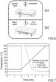
- Fig. 7 illustrates by way of example the ideal temperature trends of the three components during an analysis step. These trends are not achievable with the prior art both for the aforementioned reasons and for problems of thermal transmission between two elements even when they are separated.
- capillary tubes are used for the passage of the fluid between the components, which is disadvantageous for the following reasons:
- the object of the present invention is to provide a miniaturized system for purge & trap preconcentration and subsequent (gas-)chromatography separation of sample mixtures, which solves all or part of the problems of the prior art.
- the invention concerns a miniaturized gas-chromatography system, based on MEMS components for the analysis of gaseous trace samples by means of purge & trap preconcentration with thermal desorption, wherein the following features may be understood individually and in any combination, respecting the technical concept of the invention.
- the gas-chromatography device 100 in a first embodiment according to the invention, comprises a chromatography column unit 150 and a preconcentrator 160 (also called "thermal desorption trap").
- An injector unit 140 is assembled (e.g. in a bridge) between the two. The assembly is preferably carried out through O-rings 180 which are squeezed between two rigid parts in order to form fluidic connections (more generally any fluidic connector or coupling may be used, even means other than O-rings).
- a fluidic head (or mechanical connection means) 170 preferably made of steel, faces the injector unit 140. Again, preferably, there is no direct contact between the fluidic head 170 and the injector unit 140; rather the contact occurs through O-rings 180.
- O-rings are not only to be considered as a fluidic interconnection method, but also allows the parts interconnected by the O-rings to be kept at different temperatures from each other, solving or helping to solve the problems of the prior art.
- An O-ring in effect, allows for a temperature gradient between the parts that face the two sides of the O-ring, also facilitated by the presence of an air gap.
- the separation column is a column preferably comprised in the group which includes: microfabricated packed GC columns, microfabricated semi-packed GC columns, microfabricated capillary GC columns, microfabricated multi-capillary GC columns, tubular porous layer GC columns and microfabricated GC columns based on ionic liquids.
- the thermal desorption trap 160 may be filled with a suitable absorbent comprised in the set of porous polymers, graphitized carbons, molecular sieves, zeolite molecular sieves, or multiple bed sorbent traps based on sequences of any one of the aforementioned sorbents.
- the thermal desorption trap and the chromatography separation column are both filled with graphitized carbons with different specific surfaces, therefore they are suitable for high temperature ramps in the presence of oxygen in the carrier gas and thus allow the use of purified air as carrier gas.
- one or two layers of material 120,130 may be mounted as a medium between the injector unit 140 and the solenoid valves 110.
- a first layer 130 is preferably made of aluminum and serves as structural reinforcement and protection for a second layer 120, which is made of a heat-insulating material, so that the solenoid valves 110 do not heat up when in contact with the injector unit 140.
- the fluid flows inside the device 100 of the invention are shown.
- the inlet and outlet flows of the sample the overpressure +dP of the carrier gas (corresponding in the figures to “carrier gas inlet”)
- the underpressure -dP corresponding in the figures to “sample outlet”
- the overpressure +dP pushes the carrier gas into the gas-chromatography column 150; the gas then passes into the injector unit 140 and finally into the detector (one or more, not shown).
- This circuit is operated through the use of solenoid valves 110 which however open and close other pressure-operated on/off valves, better illustrated hereinafter.
- the sample inlet is indicated at 173, the overpressure +dP at 171, the underpressure -dP at 172, and the outlet to the detector at 174.
- the inlet channel 125 of the actuation pressure is used in the thermally insulating layer 120.
- the channels 171-174 are advantageously made in the fluidic head 170, and this is preferably made of steel: in effect this material has a high degree of passivation (i.e. it is possible to passivate the surfaces of the channels, for example by vitrification processes, so that they become inert).
- the gas, entering in 173 is directed towards the injector, which distributes the flow through the actuation of the valves V1-V5.
- the fluidic head 170 is a mechanical connection means between the injector, the preconcentrator and the separation column, which are mechanically independent (separated). It also guarantees the fluidic interconnection between the injector and the apparatuses upstream and downstream of the system.
- the preconcentrator 160, the chromatography separation column 150 and the injector 140 are connected fluidically through fluidic connectors 180 interposed on one side between said injector 140 and said preconcentrator 160 and on the other between said injector 140 and said chromatography separation column 150.
- O-rings 180 are illustrated in the formation of some ducts, other means with the same function may be used in the device according to the invention.
- gaskets or connections with metal alloys may be used, e.g. a fluidic connector based on soft metal (soft metallic seals). Fluidic connectors or sealing means will thus more generally refer to the O-rings or gaskets or other means.
- the gas-chromatography column 150, the preconcentrator 160 and the injection unit 140 are made as MEMS to provide a miniaturization to the device.
- the injection unit 140 works both as an injector and as a fluidic manifold (connection) to be interconnected to the preconcentrator and to the gas-chromatography column, in order to minimize dead volumes while allowing keeping the entire analytical circuit penetrated by the sample at high temperatures (since MEMS valves are resistant to high temperatures), and thus to optimize the analytical performance.
- valves V1-V5 are preferably all in the injection unit 140.
- the circuit in the state shown in Fig. 4 has three valves open and two closed, in order to create, due to the underpressure -dP present at the sample outlet, a flow into the preconcentrator 160 so that the analytes are concentrated there.
- the gas-chromatography column is however affected by a flow controlled by the overpressure +dP present at the inlet of the carrier gas, otherwise it may be subject to contamination.
- the closing/opening of the valves is reversed, so that from the preconcentrator suitably heated for the release of the sample, the gas, pushed by the overpressure +dP present at the entrance of the carrier gas, passes to the gas-chromatography column 150 and thus to the detector (not shown) .
- the MEMS valves are controlled by the solenoid valve group 110.
- Fig. 6 illustrates the operation of the MEMS valves.
- These on/off valves are preferably polymeric micro-diaphragms obtained between two silicon wafers.
- the two pumps (or more generally gas handling or pressure creating means) for overpressure and underpressure are preferably different.
- the preconcentrator 160 is in thermal connection or integrates (constructing them e.g. as MEMS) one or more heaters and one or more temperature sensors (not shown) .
- the same may be provided for the chromatography column and for the injector.
- Thermal connection means any connection (by contact, radiant, etc.; internal or external) capable of conveying heat from the heater to the heated element (preconcentrator and chromatography column).
- a heater may also be provided for the fluidic head 170.
- a heater may also be provided for the fluidic head 170.
- Kapton/Copper electric heaters but one could also use simple resistance heaters or armored heater plugs.
- the MEMS injector chip 140 will be heated by irradiation from the fluidic head 170, which is very close thereto.
- the system may comprise a sampling loop in the injector 140 to allow the use of either a thermal desorption trap or a sampling loop.
- loop injection could be used, which guarantees faster analysis (not requiring additional preconcentration and release cycles) and more precisely controlled volumetric injections.
- valves are not all inserted in a single component as in the present invention.
- the MEMS injector acts as a "microfluidic manifold" (which could also be called “pneumatic motherboard” or “microfluidic motherboard”) to interconnect the MEMS preconcentrator to the GC MEMS column, thus creating a set of 3 interconnected MEMS directly facing each other (e.g. through micro-O-rings), without the aid of additional components such as tubes/capillaries/manifolds.
- microfluidic manifold which could also be called “pneumatic motherboard” or “microfluidic motherboard”
- the detector is not specific to the present invention, as it could be any type of detector used in GC; only TCD (Thermal Conductivity Detector), PID (Photoionization Detector), FID (Flame Ionization Detector), ECD (Electron Capture Detector), PDD (Pulsed Discharge Detector), MOX (Metal Oxide Detector), IMS (Ion Mobility Spectrometer Detector), MS (Mass Spectrometer Detector), IRAS (Infrared Absorption Detector), photoacoustic detectors, and electrochemical sensors are cited by way of example.
- the system according to the invention may be used, according to the applications, with GC MEMS columns of different kinds (capillaries, packed), that use inert carrier gases from cylinders (e.g. nitrogen, helium) or generated independently (e.g. hydrogen by electrolysis), or in some cases with simple filtered air.
- cylinders e.g. nitrogen, helium
- hydrogen by electrolysis e.g. hydrogen by electrolysis
- the system according to the invention comprising 3 MEMS (preconcentrator, microfluidic injector/manifold, GC column), solenoid valves (which are used only for the pressure actuation of the injection valves), mounting supports, heaters, etc., measures only a few cubic centimeters.
- the system according to the invention may be used according to the following steps:
- the heaters of the injector, of the preconcentrator and of the separation column in a miniaturized device are actuated independently as described above.
- Fig. 7 wherein three exemplifying desirable temperature trends in the three respective injector, preconcentrator and separation column components are illustrated. Due to the independent actuation of the three heaters, these trends are easily obtainable according to the invention, which is a miniaturized apparatus.
- an analysis system is provided with a first and second microfabricated gas-chromatography column in GCxGC configuration, as well as a microfabricated modulator injector.
- the modulator may implement two states of the fluid system, where:
- the two states are still implemented by the modulator through a series of microfabricated valves, wherein, again, the injector chip also acts as a pneumatic manifold directly connecting the two GC columns.
- the invention allows, among other things, for the extreme miniaturization of a system for the purge & trap preconcentration and the subsequent (gas-)chromatography separation of sample mixtures, thus permitting high sensitivity and high selectivity to be obtained.
- the "all-MEMS" construction of the system unlike the state of the art, allows one to work at higher temperatures, since all the components penetrated by the sample are silicon-based and therefore resistant to high temperatures. This also allows the analysis of high-boiling substances.
- the injector, the preconcentrator and the separation column follow independent and separate thermal trends, thus avoiding the problem of condensed and unanalyzed molecules and optimizing the efficiency and reliability of the analysis. Moreover, this is achieved without the use of interconnecting tubes and capillaries with the following advantages:
- the invention may be used in the following fields, listed by way of non-exhaustive example: field analysis of complex samples; safety & security (explosives, CBRNe), industrial monitoring, monitoring of environments hazardous to the health of operators, biomedical analysis (e.g. breath analysis), environmental/air quality, indoor air quality, agro-food, monitoring of industrial processes, energy and natural gas (odorant quantification).
- field analysis of complex samples e.g., safety & security (explosives, CBRNe), industrial monitoring, monitoring of environments hazardous to the health of operators, biomedical analysis (e.g. breath analysis), environmental/air quality, indoor air quality, agro-food, monitoring of industrial processes, energy and natural gas (odorant quantification).
Landscapes
- Chemical & Material Sciences (AREA)
- Analytical Chemistry (AREA)
- Physics & Mathematics (AREA)
- Health & Medical Sciences (AREA)
- Life Sciences & Earth Sciences (AREA)
- Biochemistry (AREA)
- General Health & Medical Sciences (AREA)
- General Physics & Mathematics (AREA)
- Immunology (AREA)
- Pathology (AREA)
- Nanotechnology (AREA)
- Engineering & Computer Science (AREA)
- Sampling And Sample Adjustment (AREA)
- Investigating Or Analysing Materials By Optical Means (AREA)
Claims (12)
- Gaschromatografie-Analysesystem (100) zur Analyse einer Testprobe, die mindestens einen Analyten enthält, das Einrichtungen zum Handhaben eines Trägergases, einen MEMS-Injektor (140) in thermischer Verbindung mit einem oder mehreren Injektorheizungen und einem oder mehreren Injektortemperatursensoren sowie mindestens einen Detektor des mindestens einen Analyten umfasst, wobei auf einer ersten Seite des MEMS-Injektors (140) Folgendes durch entsprechende fluidische Verbindungen mit dem MEMS-Injektor fluidisch verbunden ist:- ein MEMS-Vorkonzentrator (160) in thermischer Verbindung mit einer oder mehreren Vorkonzentratorheizungen und einem oder mehreren Vorkonzentratortemperatursensoren;- eine MEMS-Chromatografie-Trennsäule (150) in thermischer Verbindung mit einer oder mehreren Trennsäulenheizungen und einem oder mehreren Trennsäulentemperatursensoren;- ein fluidischer Kopf (170), der den Injektor (140), den Vorkonzentrator (160) und die Trennsäule (150) mechanisch miteinander verbindet, die mechanisch unabhängig und thermisch getrennt sind, wobei der fluidische Kopf (170) eine Reihe von Kanälen (171, 172, 173, 174) umfasst, die konfiguriert sind, um den Strom des Trägergases und/oder der zu analysierenden Probe in Richtung des Injektors (140) und von dort in Richtung des Vorkonzentrators (160) und/oder in Richtung der Chromatografie-Trennsäule (150) und/oder in Richtung des mindestens einen Detektors zu ermöglichen;wobei:- die jeweiligen fluidischen Verbindungen Dichtungseinrichtungen (180) sind, die zwischen dem MEMS-Injektor (140) und dem MEMS-Vorkonzentrator (160) sowie zwischen dem MEMS-Injektor (140) und der MEMS-Chromatografie-Trennsäule (150) angeordnet sind;- der MEMS-Injektor (140) eine Reihe von MEMS-Ein/Aus-Ventilen (V1, V2, V3, V4, V5) umfasst, die an jeweiligen Punkten des Injektors (140) positioniert sind, konfiguriert, und angepasst, um:wobei auf einer zweiten Seite des MEMS-Injektors (140) gegenüber der ersten Seite Folgendes in aufeinanderfolgender Reihenfolge vom MEMS-Injektor bereitgestellt wird:o in einem ersten Zustand die zu analysierende Probe so in den Vorkonzentrator (160) strömen zu lassen, dass der mindestens eine Analyt darin gespeichert wird, und gleichzeitig das Trägergas durch die Trennsäule strömen zu lassen;o in einem zweiten Zustand das Trägergas zu verwenden, um den mindestens einen Analyten vom Vorkonzentrator (160) zur Chromatografie-Trennsäule (150) und schließlich zum Detektor strömen zu lassen;- ein Abstandshalter (120) aus wärmeisolierendem Material;- eine Reihe von Magnetventilen (110), die konfiguriert sind, um die Reihe von Ventilen (V1, V2, V3, V4, V5) zu steuern.
- System (100) nach Anspruch 1, wobei eine strukturelle Verstärkungs- und Schutzschicht (130) zwischen dem Abstandshalter (120) aus wärmeisolierendem Material und der Reihe von Ventilen (V1, V2, V3, V4, V5) angeordnet ist.
- System nach Anspruch 2, wobei die strukturelle Verstärkungs- und Schutzschicht (130) ein Metallabstandshalter ist.
- System (100) nach einem der Ansprüche 1 bis 3, wobei das wärmeisolierende Material (120) PEEK ist.
- System (100) nach einem oder mehreren der Ansprüche 1 bis 4, wobei der fluidische Kopf (170) aus Stahl besteht.
- System (100) nach einem oder mehreren der Ansprüche 1 bis 5, wobei die Dichtungseinrichtungen O-Ringe (180) sind.
- System (100) nach einem oder mehreren der vorhergehenden Ansprüche, wobei sich zwischen den Magnetventilen (110) und dem Injektor (140) eine Reihe von Betätigungskanälen (135) erstreckt, die konfiguriert und geeignet sind, um die Reihe von Ventilen (V1, V2, V3, V4, V5) durch Druck zu betätigen.
- System (100) nach einem oder mehreren der vorhergehenden Ansprüche, wobei die Reihe von Ventilen (V1, V2, V3, V4, V5) mindestens 5 Ventile umfasst, im ersten Zustand drei Ventile offen und zwei geschlossen sind, und umgekehrt im zweiten Zustand.
- System (100) nach einem oder mehreren der vorhergehenden Ansprüche, wobei der Vorkonzentrator (160) insbesondere als MEMS die eine oder mehreren Vorkonzentratorheizungen und den einen oder die mehreren Vorkonzentratortemperatursensoren integriert und die Trennsäule (150), insbesondere als MEMS, die eine oder mehreren Trennsäulenheizungen und den einen oder die mehreren Trennsäulensensoren integriert.
- System (100) nach einem oder mehreren der vorhergehenden Ansprüche, wobei der Injektor (140), insbesondere als MEMS, die eine oder mehreren Injektorheizungen und den einen oder die mehreren Injektortemperatursensoren integriert.
- System (100) nach einem oder mehreren der vorhergehenden Ansprüche, wobei der Injektor (140) eine Probenahmeschleife umfasst, aus der die Probe entnommen wird, die so angeschlossen ist, dass sie bei Verwendung den Vorkonzentrator (160) ausschließt.
- Gaschromatografie-Analyseverfahren, das die Durchführung der folgenden Schritte umfasst:A. Bereitstellen eines Gaschromatografie-Analysesystems (100), wie in einem oder mehreren der Ansprüche 1 bis 11 definiert;B. Betätigen der Reihe von Magnetventilen (110), um die Ventile der Reihe von Ventilen (V1, V2, V3, V4, V5) zu öffnen und zu schließen, um den ersten Zustand zu erreichen;C. Einstellen der Temperatur des Injektors (140) durch die eine oder mehreren Injektorheizungen auf eine Temperatur, um die Kondensation hochsiedender Moleküle zu vermeiden;D. Einstellen der Temperatur des Vorkonzentrators (160) mittels der einen oder der mehreren Vorkonzentratorheizungen und des einen oder der mehreren Vorkonzentratortemperatursensoren;E. Betätigen der Reihe von Magnetventilen (110), um die Ventile der Reihe von Ventilen (V1, V2, V3, V4, V5) zu öffnen und zu schließen, um den zweiten Zustand zu erreichen;F. Einstellen der Temperatur der Chromatografie-Trennsäule (150) mittels der einen oder mehreren Trennsäulenheizungen und eines oder mehrerer Trennsäulentemperatursensoren; undG. Betätigen des mindestens einen Detektors und Erfassen der Konzentration des mindestens einen Analyten.
Applications Claiming Priority (2)
| Application Number | Priority Date | Filing Date | Title |
|---|---|---|---|
| IT102019000002519A IT201900002519A1 (it) | 2019-02-21 | 2019-02-21 | Sistema miniaturizzato per la pre-concentrazione e la successiva separazione (gas-)cromatografica di miscele di campioni |
| PCT/IB2020/051046 WO2020170070A1 (en) | 2019-02-21 | 2020-02-11 | Miniaturized system for the pre-concentration and subsequent gas-chromatographic separation of sample mixtures |
Publications (2)
| Publication Number | Publication Date |
|---|---|
| EP3928075A1 EP3928075A1 (de) | 2021-12-29 |
| EP3928075B1 true EP3928075B1 (de) | 2024-04-03 |
Family
ID=66589786
Family Applications (1)
| Application Number | Title | Priority Date | Filing Date |
|---|---|---|---|
| EP20706834.7A Active EP3928075B1 (de) | 2019-02-21 | 2020-02-11 | Miniaturisiertes system zur vorkonzentrierung und anschliessenden gaschromatografischen trennung von probengemischen und entsprechendes gaschromatographes analyseverfahren |
Country Status (3)
| Country | Link |
|---|---|
| EP (1) | EP3928075B1 (de) |
| IT (1) | IT201900002519A1 (de) |
| WO (1) | WO2020170070A1 (de) |
Families Citing this family (2)
| Publication number | Priority date | Publication date | Assignee | Title |
|---|---|---|---|---|
| US11927574B2 (en) * | 2017-05-15 | 2024-03-12 | The Regents Of The University Of Michigan | Progressive cellular architecture for microfabricated gas chromatograph |
| FR3156439B1 (fr) | 2023-12-06 | 2025-10-24 | Commissariat Energie Atomique | Dispositif microfluidique employé pour le prélèvement, la préconcentration, la séparation ou la détection de gaz |
Family Cites Families (2)
| Publication number | Priority date | Publication date | Assignee | Title |
|---|---|---|---|---|
| SG11201808432VA (en) | 2016-04-15 | 2018-10-30 | Univ Yale | System, apparatus, and method for monitoring organic compounds in a gas environment |
| US20180164260A1 (en) * | 2016-12-08 | 2018-06-14 | Masoud Agah | Chip-Scale Gas Chromatography |
-
2019
- 2019-02-21 IT IT102019000002519A patent/IT201900002519A1/it unknown
-
2020
- 2020-02-11 EP EP20706834.7A patent/EP3928075B1/de active Active
- 2020-02-11 WO PCT/IB2020/051046 patent/WO2020170070A1/en not_active Ceased
Also Published As
| Publication number | Publication date |
|---|---|
| WO2020170070A1 (en) | 2020-08-27 |
| EP3928075A1 (de) | 2021-12-29 |
| IT201900002519A1 (it) | 2020-08-21 |
Similar Documents
| Publication | Publication Date | Title |
|---|---|---|
| Zampolli et al. | Compact-GC platform: A flexible system integration strategy for a completely microsystems-based gas-chromatograph | |
| US11796515B2 (en) | Gas analyte spectrum sharpening and separation with multi-dimensional micro-GC for gas chromatography analysis | |
| Garg et al. | Zebra GC: A mini gas chromatography system for trace-level determination of hazardous air pollutants | |
| US8127595B2 (en) | Pre-concentrator and sample interface | |
| EP3443317B1 (de) | System und verfahren zur überwachung organischer verbindungen in einer gasumgebung | |
| US8114200B2 (en) | Multi-dimensional portable gas chromatograph system | |
| Liu et al. | Smart multi-channel two-dimensional micro-gas chromatography for rapid workplace hazardous volatile organic compounds measurement | |
| Qin et al. | iGC2: An architecture for micro gas chromatographs utilizing integrated bi-directional pumps and multi-stage preconcentrators | |
| Kaanta et al. | A monolithically fabricated gas chromatography separation column with an integrated high sensitivity thermal conductivity detector | |
| Alfeeli et al. | MEMS-based selective preconcentration of trace level breath analytes | |
| Han et al. | Micro-fabricated packed metal gas preconcentrator for enhanced monitoring of ultralow concentration of isoprene | |
| EP3928075A1 (de) | Miniaturisiertes system zur vorkonzentrierung und anschliessenden gaschromatografischen trennung von probengemischen | |
| Sukaew et al. | Multi-stage preconcentrator/focuser module designed to enable trace level determinations of trichloroethylene in indoor air with a microfabricated gas chromatograph | |
| Thamatam et al. | Fluidic and Electrical Modular Interfacing: A modular approach to micro total analytical systems and micro gas chromatography | |
| US7524363B2 (en) | Gas chromatograph column assembly | |
| US5846292A (en) | Chromatograph with column extraction | |
| EP3980768A1 (de) | System zur chemischen analyse mittels gaschromatografischer trennung und fotoakustischer spektroskopie von proben | |
| Azzouz et al. | Recent advances in micro-gas chromatography—The opportunities and the challenges | |
| Qin et al. | A micro gas chromatograph with integrated bi-directional pump for quantitative analyses | |
| US7485176B2 (en) | Compact thermal conductivity detector | |
| Chan et al. | Microfabricated preconcentrator for quantitative analysis of low concentration volatile organic compounds | |
| Fan et al. | Portable multi-dimensional gas chromatography device for rapid field analysis of chemical compounds | |
| Ricoul et al. | Development of an original compact multigas detection system based on MEMS components | |
| Akbar et al. | A Micro Collector Injector (µCOIN) for µGC Systems |
Legal Events
| Date | Code | Title | Description |
|---|---|---|---|
| STAA | Information on the status of an ep patent application or granted ep patent |
Free format text: STATUS: UNKNOWN |
|
| STAA | Information on the status of an ep patent application or granted ep patent |
Free format text: STATUS: THE INTERNATIONAL PUBLICATION HAS BEEN MADE |
|
| PUAI | Public reference made under article 153(3) epc to a published international application that has entered the european phase |
Free format text: ORIGINAL CODE: 0009012 |
|
| STAA | Information on the status of an ep patent application or granted ep patent |
Free format text: STATUS: REQUEST FOR EXAMINATION WAS MADE |
|
| 17P | Request for examination filed |
Effective date: 20210817 |
|
| AK | Designated contracting states |
Kind code of ref document: A1 Designated state(s): AL AT BE BG CH CY CZ DE DK EE ES FI FR GB GR HR HU IE IS IT LI LT LU LV MC MK MT NL NO PL PT RO RS SE SI SK SM TR |
|
| DAV | Request for validation of the european patent (deleted) | ||
| DAX | Request for extension of the european patent (deleted) | ||
| P01 | Opt-out of the competence of the unified patent court (upc) registered |
Effective date: 20230526 |
|
| REG | Reference to a national code |
Ref country code: DE Ref legal event code: R079 Ipc: G01N0030080000 Ref country code: DE Ref legal event code: R079 Ref document number: 602020028285 Country of ref document: DE Free format text: PREVIOUS MAIN CLASS: G01N0001400000 Ipc: G01N0030080000 |
|
| GRAP | Despatch of communication of intention to grant a patent |
Free format text: ORIGINAL CODE: EPIDOSNIGR1 |
|
| STAA | Information on the status of an ep patent application or granted ep patent |
Free format text: STATUS: GRANT OF PATENT IS INTENDED |
|
| INTG | Intention to grant announced |
Effective date: 20231124 |
|
| RIC1 | Information provided on ipc code assigned before grant |
Ipc: G01N 30/20 20060101ALN20231113BHEP Ipc: G01N 1/40 20060101ALI20231113BHEP Ipc: G01N 30/60 20060101ALI20231113BHEP Ipc: G01N 30/08 20060101AFI20231113BHEP |
|
| GRAS | Grant fee paid |
Free format text: ORIGINAL CODE: EPIDOSNIGR3 |
|
| GRAA | (expected) grant |
Free format text: ORIGINAL CODE: 0009210 |
|
| STAA | Information on the status of an ep patent application or granted ep patent |
Free format text: STATUS: THE PATENT HAS BEEN GRANTED |
|
| AK | Designated contracting states |
Kind code of ref document: B1 Designated state(s): AL AT BE BG CH CY CZ DE DK EE ES FI FR GB GR HR HU IE IS IT LI LT LU LV MC MK MT NL NO PL PT RO RS SE SI SK SM TR |
|
| REG | Reference to a national code |
Ref country code: CH Ref legal event code: EP |
|
| REG | Reference to a national code |
Ref country code: IE Ref legal event code: FG4D |
|
| REG | Reference to a national code |
Ref country code: DE Ref legal event code: R096 Ref document number: 602020028285 Country of ref document: DE |
|
| REG | Reference to a national code |
Ref country code: LT Ref legal event code: MG9D |
|
| REG | Reference to a national code |
Ref country code: NL Ref legal event code: MP Effective date: 20240403 |
|
| REG | Reference to a national code |
Ref country code: AT Ref legal event code: MK05 Ref document number: 1672878 Country of ref document: AT Kind code of ref document: T Effective date: 20240403 |
|
| PG25 | Lapsed in a contracting state [announced via postgrant information from national office to epo] |
Ref country code: NL Free format text: LAPSE BECAUSE OF FAILURE TO SUBMIT A TRANSLATION OF THE DESCRIPTION OR TO PAY THE FEE WITHIN THE PRESCRIBED TIME-LIMIT Effective date: 20240403 |
|
| PG25 | Lapsed in a contracting state [announced via postgrant information from national office to epo] |
Ref country code: NL Free format text: LAPSE BECAUSE OF FAILURE TO SUBMIT A TRANSLATION OF THE DESCRIPTION OR TO PAY THE FEE WITHIN THE PRESCRIBED TIME-LIMIT Effective date: 20240403 |
|
| PG25 | Lapsed in a contracting state [announced via postgrant information from national office to epo] |
Ref country code: IS Free format text: LAPSE BECAUSE OF FAILURE TO SUBMIT A TRANSLATION OF THE DESCRIPTION OR TO PAY THE FEE WITHIN THE PRESCRIBED TIME-LIMIT Effective date: 20240803 |
|
| PG25 | Lapsed in a contracting state [announced via postgrant information from national office to epo] |
Ref country code: BG Free format text: LAPSE BECAUSE OF FAILURE TO SUBMIT A TRANSLATION OF THE DESCRIPTION OR TO PAY THE FEE WITHIN THE PRESCRIBED TIME-LIMIT Effective date: 20240403 |
|
| PG25 | Lapsed in a contracting state [announced via postgrant information from national office to epo] |
Ref country code: HR Free format text: LAPSE BECAUSE OF FAILURE TO SUBMIT A TRANSLATION OF THE DESCRIPTION OR TO PAY THE FEE WITHIN THE PRESCRIBED TIME-LIMIT Effective date: 20240403 Ref country code: FI Free format text: LAPSE BECAUSE OF FAILURE TO SUBMIT A TRANSLATION OF THE DESCRIPTION OR TO PAY THE FEE WITHIN THE PRESCRIBED TIME-LIMIT Effective date: 20240403 |
|
| PG25 | Lapsed in a contracting state [announced via postgrant information from national office to epo] |
Ref country code: GR Free format text: LAPSE BECAUSE OF FAILURE TO SUBMIT A TRANSLATION OF THE DESCRIPTION OR TO PAY THE FEE WITHIN THE PRESCRIBED TIME-LIMIT Effective date: 20240704 |
|
| PG25 | Lapsed in a contracting state [announced via postgrant information from national office to epo] |
Ref country code: PT Free format text: LAPSE BECAUSE OF FAILURE TO SUBMIT A TRANSLATION OF THE DESCRIPTION OR TO PAY THE FEE WITHIN THE PRESCRIBED TIME-LIMIT Effective date: 20240805 |
|
| PG25 | Lapsed in a contracting state [announced via postgrant information from national office to epo] |
Ref country code: ES Free format text: LAPSE BECAUSE OF FAILURE TO SUBMIT A TRANSLATION OF THE DESCRIPTION OR TO PAY THE FEE WITHIN THE PRESCRIBED TIME-LIMIT Effective date: 20240403 |
|
| PG25 | Lapsed in a contracting state [announced via postgrant information from national office to epo] |
Ref country code: CZ Free format text: LAPSE BECAUSE OF FAILURE TO SUBMIT A TRANSLATION OF THE DESCRIPTION OR TO PAY THE FEE WITHIN THE PRESCRIBED TIME-LIMIT Effective date: 20240403 |
|
| PG25 | Lapsed in a contracting state [announced via postgrant information from national office to epo] |
Ref country code: AT Free format text: LAPSE BECAUSE OF FAILURE TO SUBMIT A TRANSLATION OF THE DESCRIPTION OR TO PAY THE FEE WITHIN THE PRESCRIBED TIME-LIMIT Effective date: 20240403 |
|
| PG25 | Lapsed in a contracting state [announced via postgrant information from national office to epo] |
Ref country code: PL Free format text: LAPSE BECAUSE OF FAILURE TO SUBMIT A TRANSLATION OF THE DESCRIPTION OR TO PAY THE FEE WITHIN THE PRESCRIBED TIME-LIMIT Effective date: 20240403 |
|
| PG25 | Lapsed in a contracting state [announced via postgrant information from national office to epo] |
Ref country code: LV Free format text: LAPSE BECAUSE OF FAILURE TO SUBMIT A TRANSLATION OF THE DESCRIPTION OR TO PAY THE FEE WITHIN THE PRESCRIBED TIME-LIMIT Effective date: 20240403 |
|
| PG25 | Lapsed in a contracting state [announced via postgrant information from national office to epo] |
Ref country code: PT Free format text: LAPSE BECAUSE OF FAILURE TO SUBMIT A TRANSLATION OF THE DESCRIPTION OR TO PAY THE FEE WITHIN THE PRESCRIBED TIME-LIMIT Effective date: 20240805 Ref country code: PL Free format text: LAPSE BECAUSE OF FAILURE TO SUBMIT A TRANSLATION OF THE DESCRIPTION OR TO PAY THE FEE WITHIN THE PRESCRIBED TIME-LIMIT Effective date: 20240403 Ref country code: NO Free format text: LAPSE BECAUSE OF FAILURE TO SUBMIT A TRANSLATION OF THE DESCRIPTION OR TO PAY THE FEE WITHIN THE PRESCRIBED TIME-LIMIT Effective date: 20240703 Ref country code: LV Free format text: LAPSE BECAUSE OF FAILURE TO SUBMIT A TRANSLATION OF THE DESCRIPTION OR TO PAY THE FEE WITHIN THE PRESCRIBED TIME-LIMIT Effective date: 20240403 Ref country code: IS Free format text: LAPSE BECAUSE OF FAILURE TO SUBMIT A TRANSLATION OF THE DESCRIPTION OR TO PAY THE FEE WITHIN THE PRESCRIBED TIME-LIMIT Effective date: 20240803 Ref country code: HR Free format text: LAPSE BECAUSE OF FAILURE TO SUBMIT A TRANSLATION OF THE DESCRIPTION OR TO PAY THE FEE WITHIN THE PRESCRIBED TIME-LIMIT Effective date: 20240403 Ref country code: GR Free format text: LAPSE BECAUSE OF FAILURE TO SUBMIT A TRANSLATION OF THE DESCRIPTION OR TO PAY THE FEE WITHIN THE PRESCRIBED TIME-LIMIT Effective date: 20240704 Ref country code: FI Free format text: LAPSE BECAUSE OF FAILURE TO SUBMIT A TRANSLATION OF THE DESCRIPTION OR TO PAY THE FEE WITHIN THE PRESCRIBED TIME-LIMIT Effective date: 20240403 Ref country code: ES Free format text: LAPSE BECAUSE OF FAILURE TO SUBMIT A TRANSLATION OF THE DESCRIPTION OR TO PAY THE FEE WITHIN THE PRESCRIBED TIME-LIMIT Effective date: 20240403 Ref country code: CZ Free format text: LAPSE BECAUSE OF FAILURE TO SUBMIT A TRANSLATION OF THE DESCRIPTION OR TO PAY THE FEE WITHIN THE PRESCRIBED TIME-LIMIT Effective date: 20240403 Ref country code: BG Free format text: LAPSE BECAUSE OF FAILURE TO SUBMIT A TRANSLATION OF THE DESCRIPTION OR TO PAY THE FEE WITHIN THE PRESCRIBED TIME-LIMIT Effective date: 20240403 Ref country code: AT Free format text: LAPSE BECAUSE OF FAILURE TO SUBMIT A TRANSLATION OF THE DESCRIPTION OR TO PAY THE FEE WITHIN THE PRESCRIBED TIME-LIMIT Effective date: 20240403 Ref country code: RS Free format text: LAPSE BECAUSE OF FAILURE TO SUBMIT A TRANSLATION OF THE DESCRIPTION OR TO PAY THE FEE WITHIN THE PRESCRIBED TIME-LIMIT Effective date: 20240703 |
|
| REG | Reference to a national code |
Ref country code: DE Ref legal event code: R097 Ref document number: 602020028285 Country of ref document: DE |
|
| PG25 | Lapsed in a contracting state [announced via postgrant information from national office to epo] |
Ref country code: DK Free format text: LAPSE BECAUSE OF FAILURE TO SUBMIT A TRANSLATION OF THE DESCRIPTION OR TO PAY THE FEE WITHIN THE PRESCRIBED TIME-LIMIT Effective date: 20240403 |
|
| PG25 | Lapsed in a contracting state [announced via postgrant information from national office to epo] |
Ref country code: EE Free format text: LAPSE BECAUSE OF FAILURE TO SUBMIT A TRANSLATION OF THE DESCRIPTION OR TO PAY THE FEE WITHIN THE PRESCRIBED TIME-LIMIT Effective date: 20240403 |
|
| PG25 | Lapsed in a contracting state [announced via postgrant information from national office to epo] |
Ref country code: RO Free format text: LAPSE BECAUSE OF FAILURE TO SUBMIT A TRANSLATION OF THE DESCRIPTION OR TO PAY THE FEE WITHIN THE PRESCRIBED TIME-LIMIT Effective date: 20240403 Ref country code: SK Free format text: LAPSE BECAUSE OF FAILURE TO SUBMIT A TRANSLATION OF THE DESCRIPTION OR TO PAY THE FEE WITHIN THE PRESCRIBED TIME-LIMIT Effective date: 20240403 |
|
| PG25 | Lapsed in a contracting state [announced via postgrant information from national office to epo] |
Ref country code: SM Free format text: LAPSE BECAUSE OF FAILURE TO SUBMIT A TRANSLATION OF THE DESCRIPTION OR TO PAY THE FEE WITHIN THE PRESCRIBED TIME-LIMIT Effective date: 20240403 |
|
| PG25 | Lapsed in a contracting state [announced via postgrant information from national office to epo] |
Ref country code: SM Free format text: LAPSE BECAUSE OF FAILURE TO SUBMIT A TRANSLATION OF THE DESCRIPTION OR TO PAY THE FEE WITHIN THE PRESCRIBED TIME-LIMIT Effective date: 20240403 Ref country code: SK Free format text: LAPSE BECAUSE OF FAILURE TO SUBMIT A TRANSLATION OF THE DESCRIPTION OR TO PAY THE FEE WITHIN THE PRESCRIBED TIME-LIMIT Effective date: 20240403 Ref country code: RO Free format text: LAPSE BECAUSE OF FAILURE TO SUBMIT A TRANSLATION OF THE DESCRIPTION OR TO PAY THE FEE WITHIN THE PRESCRIBED TIME-LIMIT Effective date: 20240403 Ref country code: EE Free format text: LAPSE BECAUSE OF FAILURE TO SUBMIT A TRANSLATION OF THE DESCRIPTION OR TO PAY THE FEE WITHIN THE PRESCRIBED TIME-LIMIT Effective date: 20240403 Ref country code: DK Free format text: LAPSE BECAUSE OF FAILURE TO SUBMIT A TRANSLATION OF THE DESCRIPTION OR TO PAY THE FEE WITHIN THE PRESCRIBED TIME-LIMIT Effective date: 20240403 |
|
| PLBE | No opposition filed within time limit |
Free format text: ORIGINAL CODE: 0009261 |
|
| STAA | Information on the status of an ep patent application or granted ep patent |
Free format text: STATUS: NO OPPOSITION FILED WITHIN TIME LIMIT |
|
| 26N | No opposition filed |
Effective date: 20250106 |
|
| PG25 | Lapsed in a contracting state [announced via postgrant information from national office to epo] |
Ref country code: SI Free format text: LAPSE BECAUSE OF FAILURE TO SUBMIT A TRANSLATION OF THE DESCRIPTION OR TO PAY THE FEE WITHIN THE PRESCRIBED TIME-LIMIT Effective date: 20240403 |
|
| PG25 | Lapsed in a contracting state [announced via postgrant information from national office to epo] |
Ref country code: SE Free format text: LAPSE BECAUSE OF FAILURE TO SUBMIT A TRANSLATION OF THE DESCRIPTION OR TO PAY THE FEE WITHIN THE PRESCRIBED TIME-LIMIT Effective date: 20240403 |
|
| PG25 | Lapsed in a contracting state [announced via postgrant information from national office to epo] |
Ref country code: MC Free format text: LAPSE BECAUSE OF FAILURE TO SUBMIT A TRANSLATION OF THE DESCRIPTION OR TO PAY THE FEE WITHIN THE PRESCRIBED TIME-LIMIT Effective date: 20240403 |
|
| REG | Reference to a national code |
Ref country code: CH Ref legal event code: PL |
|
| PG25 | Lapsed in a contracting state [announced via postgrant information from national office to epo] |
Ref country code: LU Free format text: LAPSE BECAUSE OF NON-PAYMENT OF DUE FEES Effective date: 20250211 |
|
| PG25 | Lapsed in a contracting state [announced via postgrant information from national office to epo] |
Ref country code: CH Free format text: LAPSE BECAUSE OF NON-PAYMENT OF DUE FEES Effective date: 20250228 |
|
| REG | Reference to a national code |
Ref country code: BE Ref legal event code: MM Effective date: 20250228 |
|
| PG25 | Lapsed in a contracting state [announced via postgrant information from national office to epo] |
Ref country code: IT Free format text: LAPSE BECAUSE OF NON-PAYMENT OF DUE FEES Effective date: 20250211 |
|
| PG25 | Lapsed in a contracting state [announced via postgrant information from national office to epo] |
Ref country code: BE Free format text: LAPSE BECAUSE OF NON-PAYMENT OF DUE FEES Effective date: 20250228 |
|
| PG25 | Lapsed in a contracting state [announced via postgrant information from national office to epo] |
Ref country code: IE Free format text: LAPSE BECAUSE OF NON-PAYMENT OF DUE FEES Effective date: 20250211 |
|
| PGFP | Annual fee paid to national office [announced via postgrant information from national office to epo] |
Ref country code: GB Payment date: 20260220 Year of fee payment: 7 |
|
| PGFP | Annual fee paid to national office [announced via postgrant information from national office to epo] |
Ref country code: DE Payment date: 20260223 Year of fee payment: 7 |
|
| PG25 | Lapsed in a contracting state [announced via postgrant information from national office to epo] |
Ref country code: IT Free format text: LAPSE BECAUSE OF NON-PAYMENT OF DUE FEES Effective date: 20250211 |
|
| PGFP | Annual fee paid to national office [announced via postgrant information from national office to epo] |
Ref country code: IT Payment date: 20251205 Year of fee payment: 7 |
|
| PGRI | Patent reinstated in contracting state [announced from national office to epo] |
Ref country code: IT Effective date: 20250630 |
|
| PGFP | Annual fee paid to national office [announced via postgrant information from national office to epo] |
Ref country code: FR Payment date: 20260130 Year of fee payment: 7 |