EP3927569B1 - Roof assembly for a work vehicle - Google Patents
Roof assembly for a work vehicle Download PDFInfo
- Publication number
- EP3927569B1 EP3927569B1 EP20728673.3A EP20728673A EP3927569B1 EP 3927569 B1 EP3927569 B1 EP 3927569B1 EP 20728673 A EP20728673 A EP 20728673A EP 3927569 B1 EP3927569 B1 EP 3927569B1
- Authority
- EP
- European Patent Office
- Prior art keywords
- sun visor
- sliding support
- locking
- roof
- roof assembly
- Prior art date
- Legal status (The legal status is an assumption and is not a legal conclusion. Google has not performed a legal analysis and makes no representation as to the accuracy of the status listed.)
- Active
Links
Images


Classifications
-
- B—PERFORMING OPERATIONS; TRANSPORTING
- B60—VEHICLES IN GENERAL
- B60J—WINDOWS, WINDSCREENS, NON-FIXED ROOFS, DOORS, OR SIMILAR DEVICES FOR VEHICLES; REMOVABLE EXTERNAL PROTECTIVE COVERINGS SPECIALLY ADAPTED FOR VEHICLES
- B60J7/00—Non-fixed roofs; Roofs with movable panels, e.g. rotary sunroofs
- B60J7/0007—Non-fixed roofs; Roofs with movable panels, e.g. rotary sunroofs moveable head-liners, screens, curtains or blinds for ceilings
- B60J7/0015—Non-fixed roofs; Roofs with movable panels, e.g. rotary sunroofs moveable head-liners, screens, curtains or blinds for ceilings roller blind
-
- B—PERFORMING OPERATIONS; TRANSPORTING
- B60—VEHICLES IN GENERAL
- B60J—WINDOWS, WINDSCREENS, NON-FIXED ROOFS, DOORS, OR SIMILAR DEVICES FOR VEHICLES; REMOVABLE EXTERNAL PROTECTIVE COVERINGS SPECIALLY ADAPTED FOR VEHICLES
- B60J3/00—Antiglare equipment associated with windows or windscreens; Sun visors for vehicles
- B60J3/02—Antiglare equipment associated with windows or windscreens; Sun visors for vehicles adjustable in position
- B60J3/0204—Sun visors
- B60J3/0213—Sun visors characterised by the mounting means
- B60J3/0234—Mounted slidably
- B60J3/0243—Mounted slidably sliding out from ceiling
Definitions
- the invention concerns a roof assembly for a vehicle, in particular a roof assembly for an agricultural vehicle such as a tractor.
- Work vehicles such as agricultural vehicles usually comprises a cabin configured to protect the user of the vehicle for dangerous impact with elements such as branches or stones.
- Such agricultural vehicles may comprise a front windscreen and a roof being provided with an opening above the driver seat, next to the front windscreen.
- sunshade assembly having at least the purpose of covering the opening on the roof.
- a sunshade assembly with the above purpose may be mounted on the roof, immediately behind the opening, to form a roof assembly and usually includes a roller blind and a rod, which is adapted to slide below the opening and carry one end of the roller blind for extending and retracting the latter.
- the rod slides between a backward position, in which the roller blind is mostly wounded, and an advanced position, in which the roller blind is unwound and covers the opening as shown in DE202007015435U1 or EP1547836 A2 .
- sunshade assemblies are also provided with a rigid sun visor carried by the rod in a pivotal manner to cover the front windscreen when the rod is in the advanced position; the rigid sun visor increases the weight supported by the rod and the occurrence of vibrations, especially when handled by the user.
- An aim of the invention is to satisfy at least one of the above-mentioned needs.
- reference numeral 1 refers to an agricultural vehicle comprising a chassis 2 provided with a cab defined by a plurality of walls, including e.g. a front wall 3 and a roof 4, for defining a driving compartment 5.
- Agricultural vehicle 1 comprises a driver seat 6 within driving compartment 5, while front wall 3 and roof 4 respectively have a front windscreen or opening 7, and a top transparent portion or opening 8, correspondingly in front of and above the driver seat 6.
- agricultural vehicle 1 comprises a sunshade assembly 10 according to the invention, which is carried by the roof 4 and configured for covering the top opening 8 and, advantageously, the front windscreen 7.
- Sunshade assembly 10 and roof 4 are both constitutive parts of a roof assembly of the vehicle 1.
- Sunshade assembly 10 comprises a frame 11, which is fixedly coupled to roof 4 behind top opening 8 and is arranged below the latter.
- Frame 11 carries in a fixed position a guide device 12 extending along a first direction A, almost parallel to roof 4, until ending next to front wall 3.
- guide device 12 extends between a back end, behind top opening 8, and a front opposite end next to front wall 3.
- guide device 12 comprises a couple of guide members 12a, more precisely a couple of rectilinear parallel rails along first direction A.
- sunshade assembly 10 comprises a deployable shade device 13, which is carried by guide device 12 and is deployable or extendable along first direction A, in such a manner to cover the top opening 8.
- the deployable shade device 13 is further deployable along a second direction B, transversal to first direction A, in such a manner to cover also the front windscreen 7.
- deployable shade device 13 comprises a sliding support, precisely a rod 14, which is coupled to the guide device 12 in a sliding manner along first direction A.
- deployable shade device 13 further comprise a first sun visor 15 and, preferably, a second sun visor 16 both having respective portions carried by rod 14 on an inner thereof, as shown in Figure 5 .
- first sun visor 15 has an end 15a carried in a fixed position by frame 11 or roof 4 and is extensible along first direction A through the displacement of rod 14 toward the front end of guide device 12.
- Sun visor 15 i.e. reaches the smallest extension, namely a retracted configuration, when rod 14 is moved to the back end of guide device 12, whereas the same sun visor 15 reaches a larger extension, namely a deployed configuration, when rod 14 is moved to the front end of guide device 12.
- second sun visor 16 is extensible along second direction B and is provided with a movable end 17, which is displaceable along second direction B between a position closest to rod 14 ( Figure 3 ), in which sun visor 16 is in a respective retracted configuration, and a position farthest from rod 14 ( Figure 2 ), in which sun visor 16 is in a respective deployed configuration such as to cover the front windscreen 7, partly in the embodiment shown.
- first sun visor 15 and, preferably, second sun visor 16 comprise respective roller blinds 20, 21, more specifically flexible curtains, which are respectively housed within rod 14 and woundable around axes C, D ( Figure 5 ) fixed with respect to rod 14 and, in the embodiment shown, both horizontal and orthogonal to the driving direction of vehicle 1.
- first and second sun visor 15, 16 are provided with corresponding return devices (not shown) of known kind that respectively operate to tension the first and second sun visor 15, 16 themselves, as well as to bring them in the retracted configuration autonomously.
- return devices are winding devices respectively coupled to roller blinds 20, 21 to wind back the roller blinds 20, 21 themselves when at least partially unwound.
- winding devices may comprise torsional spring respectively wound around axes C, D and coupled to roller blinds 20, 21 to wind back these latter as said above.
- sunshade assembly 10 further comprises a handle 22 ( Figure 10 ), which is carried by rod 14 in a fixed position, more precisely on a bottom portion of rod 14.
- sunshade assembly 10 comprises, moreover, another handle 23 (also shown in Figure 3 ), which is carried by the end 17 of second sun visor 16 in a fixed position.
- Handles 22, 23 comprise respective backs 24a, 24b that, in the embodiment shown, face to each other when end 17 is in the position closest to rod 14.
- sunshade assembly 10 comprises a known kind trigger mechanism associated to second sun visor 16 and activating in the deployed positon thereof.
- a known kind of trigger mechanism is neither illustrated nor described in further detail, for the sake of brevity.
- Handle 23 may be exploited by the user for releasing the trigger mechanism, for instance by the pressure of a button on handle 23 or by slightly pulling down handle 23.
- sunshade assembly 10 comprises a locking seat 25, which is defined by frame 11 and is adjoined to the front end of guide device 12 or, in other words, is arranged immediately downstream of guide device 12, according to the driving direction of vehicle 1.
- Locking seat 25 receives rod 14 when first sun visor 15 is in the deployed configuration; here, rod 14 disengage the guide device 12 and is movable within locking seat 25 between an incoming position, in which is aligned with guide device 12 (more precisely with both guide members 12a), and a locking position, in which is prevented from escaping from locking seat 25, such that the first sun visor 15 is kept in the deployed configuration against the action of the corresponding return device.
- the restraining device associated to first sun visor 15 comprises a couple of identical support elements 26, of which only one in shown in Figures 3-9 , and preferably defined by a couple of receptacles.
- Support elements 26 are respectively arranged adjacent to guide members 12a, within locking seat 25, and engaged in contact by rod 14 in the incoming position, such that rod 14 is supported by the support elements 26 in the incoming position.
- Support elements 26 are movable within locking seat 25 to carry the rod 14 toward the locking position and, more precisely, are coupled to frame 11 in a swiveling manner about a hinge axis H, fixed with respect to frame 11.
- support elements 26 are maintained, for example by means of elastic reaction of torsional springs, in a receiving position, in which form respective extensions of guide members 12a or, in other words, an extension of guide device 12, such that rod 14 can reach the incoming position by sliding along support elements 26.
- first sun visor 15 when first sun visor 15 is in the deployed configuration and rod 14 is in the locking position, the support elements 26 still support rod 14, precisely in a sliding manner, and are displaced from the receiving position, specifically rotated, such that rod 14 and first sun visor 15 cannot anymore engage with guide device 12 and come back to retracted configuration, respectively, despite the action of the corresponding return device.
- support elements 26 are brought in a separating position, where continuity between support elements 26 and guide device 12 is interrupted and frame 11 interferes with the freedom of movement of rod 14.
- frame 11 closes receptacles defined by support elements 26, such that rod 14 lying on support elements 26 ( Figures 8, 9 ) remains entrapped in a niche 28 defined by frame 11 and support elements 26.
- the restraining device associated to first sun visor 15 comprises at least one engagement member 30 carried in a fixed position by frame 11, in particular making part of frame 11, and engaging with rod 14 in a releasable manner when the latter is in the locking position, such as to limit mobility of rod 14 and, in particular, to block swiveling of support elements 26.
- the rod 14 is prevented from moving transversally to the driving direction of vehicle 1.
- two engagement members 30 are provided as protrusion towards locking seat 25 for engaging with respective seats 31 provided in the rod 14.
- Engagement members 30 are arranged below the front end of guide device 12 at a back portion of locking seat 25; in such a manner, rod 14 is pulled back by the return device for first sun visor 15 when carried by support elements 26 in the separating position. In particular, rod 14 slides along support elements 26 toward the engagement members 30, i.e. along an opposite direction to the driving direction, until seats 31 are engaged by engagement members 30. Here, rod 14 reaches the locking position.
- Handle 22 may be exploited by user for releasing the engagement between engagement members 30 and rod 14, in particular by pushing handle 22 toward handle 23. Then, once rod 14 slides along support elements 26 away from engagement members 30, support elements 26 can swivel about hinge axis H to come back to the receiving position, for instance by means of the aforementioned elastic reactions. Here, rod 14 can move toward the back end of guide device 12.
- rod 14 reaches the incoming position and first sun visor 15 the deployed configuration, in which the top opening 8 is fully covered ( Figure 7 ).
- the user pulls down handle 22 to overcome the elastic reaction of the torsional spring and bring support members 26 in the separating position ( Figure 8 ).
- the user releases handle 22 and the return device of sun visor 15 causes the sliding of rod 14 toward engagement members 30 within niche 28.
- rod 14 reaches the locking position when engagement members 30 engage seats 31, where first sun visor 15 is still in the deployed configuration ( Figure 9 ).
- the user pulls down handle 23 until end 17 reaches the position farthest to rod 14, i.e. until second sun visor 16 reaches the deployed configuration, in which cover a portion of the front windscreen 7.
- the aforementioned trigger mechanism activates and the deployable shade device 13 is fully deployed and in use.
- the user pulls down the handle 23 to release the trigger mechanism and, successively, release the same handle 23 such that the corresponding return device bring the second sun visor 16 in the retracted configuration.
- Frame 11, defining locking seat 25, is compact and simple to be manufactured.
- rod 14 has a reduced space to move but sufficient to keep efficiently the deployed configuration of first sun visor 15.
- Support elements 36 are the only movable components that are coupled to frame 11, thus rendering sunshade assembly 10 particularly simple, cost effective, and reliable. In addition, support elements 36 play a convenient supporting role for rod 14, which can therefore enter and move smoothly within locking seat 25.
- the optional second sun visor 16 carried by the same rod 14 for carrying also first sun visor 15 is useful to cover part of the front windscreen 7, so as to solve the problem of implementing a dedicated sun visor in the presence of an opened roof, like roof 4.
- roller blind 21 for sun visor 16 is extremely convenient, since only a traction force need to be exerted on frame 11 through rod 14 to deploy second sun visor 16. On the contrary, a torque and a force are needed according to known solutions with a pivotal front sun visor.
- handles 22, 23 are arranged strategically, in such a manner that a user is able to deploy the deployable shade device 13 with very simple gestures.
- guide device 12 may have a different shape or have different constructional features; in particular, only a single guide member may define guide device 12. Moreover, frame 11 may directly define guide device 12.
- Components like the second sun visor 16 or support elements 26 are not strictly necessary, so that they can be even lacking.
- Support elements 26 may be replaced by a single beam extending transversally to first direction A and shaped to receive rod 14 in the incoming position.
- Axis C, around which roller blind 20 is wound may be fixed to frame 11 or roof 4, whereas end 15a may be carried by rod 14.
- engagement members 30 may be replaced by a single engagement member with different shape or being differently arranged with respect to frame 11. Moreover, engagement member 30 may be replaced by a seat, instead of a protrusion, engaged by a corresponding protrusion on rod 14.
- Engagement members 30 are not essential to carry out the function of preventing rod 14 from escaping from locking seat 25, since the walls defining locking seat 25 may form a sufficient barrier for rod 14.
- engagement members 30 may be replaced by locking means such as an elastic element or an impulsive actuator configured to push and maintain rod 14, or support elements 26 in the locking position or in the separating position, respectively, i.e. prevent a displacement of rod 14 toward the incoming position from the locking position.
- locking means such as an elastic element or an impulsive actuator configured to push and maintain rod 14, or support elements 26 in the locking position or in the separating position, respectively, i.e. prevent a displacement of rod 14 toward the incoming position from the locking position.
Landscapes
- Engineering & Computer Science (AREA)
- Mechanical Engineering (AREA)
- Lock And Its Accessories (AREA)
- Body Structure For Vehicles (AREA)
- Automobile Manufacture Line, Endless Track Vehicle, Trailer (AREA)
- Vehicle Interior And Exterior Ornaments, Soundproofing, And Insulation (AREA)
Description
- The invention concerns a roof assembly for a vehicle, in particular a roof assembly for an agricultural vehicle such as a tractor.
- Work vehicles such as agricultural vehicles usually comprises a cabin configured to protect the user of the vehicle for dangerous impact with elements such as branches or stones.
- Such agricultural vehicles may comprise a front windscreen and a roof being provided with an opening above the driver seat, next to the front windscreen.
- Consequently, such models are also provided with a sunshade assembly having at least the purpose of covering the opening on the roof.
- A sunshade assembly with the above purpose may be mounted on the roof, immediately behind the opening, to form a roof assembly and usually includes a roller blind and a rod, which is adapted to slide below the opening and carry one end of the roller blind for extending and retracting the latter.
- More in detail, the rod slides between a backward position, in which the roller blind is mostly wounded, and an advanced position, in which the roller blind is unwound and covers the opening as shown in
DE202007015435U1 orEP1547836 A2 . - In general, the need is felt to provide the known roof assemblies with locking elements to keep the advanced position of the rod in a stable and tough manner while maintaining simplicity and lightness of this latter.
- In fact, without an effective locking of the rod in the advanced position, the same rod might move and vibrate in an uncontrolled manner, with uncomfortable effects on the user.
- The above need becomes more pressing in case the sunshade assembly is suitable for covering also the front windscreen.
- Indeed, some of the previously described sunshade assemblies are also provided with a rigid sun visor carried by the rod in a pivotal manner to cover the front windscreen when the rod is in the advanced position; the rigid sun visor increases the weight supported by the rod and the occurrence of vibrations, especially when handled by the user.
- Solutions of the above kind are disclosed, for instance, in
EP1375222B1 and inWO2008040892A1 . - Although the simplicity and compactness of such solutions, practical issues arises for stably locking the rod while allowing rotation of the visor.
- Therefore, the need is also felt to improve the latter solutions from the point of view of their stability in use and robustness in an optimized and economic manner.
- An aim of the invention is to satisfy at least one of the above-mentioned needs.
- The aforementioned aim is reached by a roof assembly for a vehicle, as claimed in the appended set of claims.
- For a better understanding of the present invention, a preferred embodiment is described in the following, by way of a non-limiting example, with reference to the attached drawings wherein:
-
Figure 1 is a lateral view of an agricultural vehicle comprising a roof assembly according to the invention; -
Figure 2 is a front view of the agricultural vehicle ofFigure 1 ; -
Figure 3 shows the roof assembly in perspective and in an enlarged scale; -
Figure 4 is a perspective view, in a further enlarged scale, of a detail of the roof assembly; -
Figure 5 is a lateral view of the detail ofFigure 4 coupled to a sliding rod of the roof assembly; -
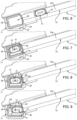
Figures 6, 7, 8, and 9 are lateral views of the detail ofFigure 4 in respective distinct operative conditions; and -
Figure 10 is an enlarged perspective view of a further detail of the roof assembly. - With reference to
Figures 1 and 2 , reference numeral 1 refers to an agricultural vehicle comprising achassis 2 provided with a cab defined by a plurality of walls, including e.g. afront wall 3 and aroof 4, for defining adriving compartment 5. - For the sake of clarity, terms like "front", "rear", "advanced", "backward", "behind" etc. refers hereinafter to a forward driving direction of vehicle 1.
- Agricultural vehicle 1 comprises a
driver seat 6 withindriving compartment 5, whilefront wall 3 androof 4 respectively have a front windscreen or opening 7, and a top transparent portion or opening 8, correspondingly in front of and above thedriver seat 6. - Furthermore, agricultural vehicle 1 comprises a
sunshade assembly 10 according to the invention, which is carried by theroof 4 and configured for covering the top opening 8 and, advantageously, thefront windscreen 7. - Sunshade
assembly 10 androof 4 are both constitutive parts of a roof assembly of the vehicle 1. - Sunshade
assembly 10 comprises aframe 11, which is fixedly coupled toroof 4 behind top opening 8 and is arranged below the latter.Frame 11 carries in a fixed position aguide device 12 extending along a first direction A, almost parallel toroof 4, until ending next tofront wall 3. - With detail,
guide device 12 extends between a back end, behind top opening 8, and a front opposite end next tofront wall 3. In particular,guide device 12 comprises a couple ofguide members 12a, more precisely a couple of rectilinear parallel rails along first direction A. - Moreover, as shown in
Figure 3 ,sunshade assembly 10 comprises adeployable shade device 13, which is carried byguide device 12 and is deployable or extendable along first direction A, in such a manner to cover thetop opening 8. - Advantageously, the
deployable shade device 13 is further deployable along a second direction B, transversal to first direction A, in such a manner to cover also thefront windscreen 7. - More in detail,
deployable shade device 13 comprises a sliding support, precisely arod 14, which is coupled to theguide device 12 in a sliding manner along first direction A. - Moreover,
deployable shade device 13 further comprise afirst sun visor 15 and, preferably, asecond sun visor 16 both having respective portions carried byrod 14 on an inner thereof, as shown inFigure 5 . - Specifically,
first sun visor 15 has anend 15a carried in a fixed position byframe 11 orroof 4 and is extensible along first direction A through the displacement ofrod 14 toward the front end ofguide device 12. - Sun
visor 15 i.e. reaches the smallest extension, namely a retracted configuration, whenrod 14 is moved to the back end ofguide device 12, whereas thesame sun visor 15 reaches a larger extension, namely a deployed configuration, whenrod 14 is moved to the front end ofguide device 12. - On the other hand,
second sun visor 16 is extensible along second direction B and is provided with amovable end 17, which is displaceable along second direction B between a position closest to rod 14 (Figure 3 ), in whichsun visor 16 is in a respective retracted configuration, and a position farthest from rod 14 (Figure 2 ), in whichsun visor 16 is in a respective deployed configuration such as to cover thefront windscreen 7, partly in the embodiment shown. - In particular,
first sun visor 15 and, preferably,second sun visor 16 compriserespective roller blinds rod 14 and woundable around axes C, D (Figure 5 ) fixed with respect torod 14 and, in the embodiment shown, both horizontal and orthogonal to the driving direction of vehicle 1. - When the first and
second sun visors roller blinds - Moreover, first and
second sun visor second sun visor - For instance, return devices are winding devices respectively coupled to
roller blinds roller blinds roller blinds - In order to ease a manual displacement of
rod 14,sunshade assembly 10 further comprises a handle 22 (Figure 10 ), which is carried byrod 14 in a fixed position, more precisely on a bottom portion ofrod 14. - Similarly,
sunshade assembly 10 comprises, moreover, another handle 23 (also shown inFigure 3 ), which is carried by theend 17 ofsecond sun visor 16 in a fixed position. -
Handles respective backs end 17 is in the position closest torod 14. - Sunshade
assembly 10 further comprises restraining devices to keep both first andsecond sun visor - For example,
sunshade assembly 10 comprises a known kind trigger mechanism associated tosecond sun visor 16 and activating in the deployed positon thereof. Such a known kind of trigger mechanism is neither illustrated nor described in further detail, for the sake of brevity.Handle 23 may be exploited by the user for releasing the trigger mechanism, for instance by the pressure of a button onhandle 23 or by slightly pulling downhandle 23. - On the other hand, for keeping
first sun visor 15 in the deployed configuration,sunshade assembly 10 comprises alocking seat 25, which is defined byframe 11 and is adjoined to the front end ofguide device 12 or, in other words, is arranged immediately downstream ofguide device 12, according to the driving direction of vehicle 1. -
Locking seat 25 receivesrod 14 whenfirst sun visor 15 is in the deployed configuration; here,rod 14 disengage theguide device 12 and is movable withinlocking seat 25 between an incoming position, in which is aligned with guide device 12 (more precisely with bothguide members 12a), and a locking position, in which is prevented from escaping fromlocking seat 25, such that thefirst sun visor 15 is kept in the deployed configuration against the action of the corresponding return device. - More in detail, the restraining device associated to
first sun visor 15 comprises a couple ofidentical support elements 26, of which only one in shown inFigures 3-9 , and preferably defined by a couple of receptacles. -
Support elements 26 are respectively arranged adjacent to guidemembers 12a, withinlocking seat 25, and engaged in contact byrod 14 in the incoming position, such thatrod 14 is supported by thesupport elements 26 in the incoming position. -
Support elements 26 are movable withinlocking seat 25 to carry therod 14 toward the locking position and, more precisely, are coupled toframe 11 in a swiveling manner about a hinge axis H, fixed with respect toframe 11. - When the
first sun visor 15 is in the retracted configuration,support elements 26 are maintained, for example by means of elastic reaction of torsional springs, in a receiving position, in which form respective extensions ofguide members 12a or, in other words, an extension ofguide device 12, such thatrod 14 can reach the incoming position by sliding alongsupport elements 26. - On the other hand, when
first sun visor 15 is in the deployed configuration androd 14 is in the locking position, thesupport elements 26 still supportrod 14, precisely in a sliding manner, and are displaced from the receiving position, specifically rotated, such thatrod 14 andfirst sun visor 15 cannot anymore engage withguide device 12 and come back to retracted configuration, respectively, despite the action of the corresponding return device. - In other words,
support elements 26 are brought in a separating position, where continuity betweensupport elements 26 andguide device 12 is interrupted andframe 11 interferes with the freedom of movement ofrod 14. In the embodiment shown,frame 11 closes receptacles defined bysupport elements 26, such thatrod 14 lying on support elements 26 (Figures 8, 9 ) remains entrapped in aniche 28 defined byframe 11 andsupport elements 26. - Preferably, the restraining device associated to
first sun visor 15 comprises at least oneengagement member 30 carried in a fixed position byframe 11, in particular making part offrame 11, and engaging withrod 14 in a releasable manner when the latter is in the locking position, such as to limit mobility ofrod 14 and, in particular, to block swiveling ofsupport elements 26. - In particular, the
rod 14 is prevented from moving transversally to the driving direction of vehicle 1. - In the embodiment shown, two
engagement members 30 are provided as protrusion towards lockingseat 25 for engaging withrespective seats 31 provided in therod 14. - In
Figure 9 , only oneengagement member 30 andseat 31 are illustrated, being preferably identical to the others not shown. -
Engagement members 30 are arranged below the front end ofguide device 12 at a back portion of lockingseat 25; in such a manner,rod 14 is pulled back by the return device forfirst sun visor 15 when carried bysupport elements 26 in the separating position. In particular,rod 14 slides alongsupport elements 26 toward theengagement members 30, i.e. along an opposite direction to the driving direction, untilseats 31 are engaged byengagement members 30. Here,rod 14 reaches the locking position. -
Handle 22 may be exploited by user for releasing the engagement betweenengagement members 30 androd 14, in particular by pushinghandle 22 towardhandle 23. Then, oncerod 14 slides alongsupport elements 26 away fromengagement members 30,support elements 26 can swivel about hinge axis H to come back to the receiving position, for instance by means of the aforementioned elastic reactions. Here,rod 14 can move toward the back end ofguide device 12. - Evidently, the spacing between
backs - The operation of the
sunshade assembly 10 is herein described with reference toFigures 6-9 . - The user of vehicle 1 pushes handle 22 along first direction A toward the
front wall 3; accordingly,rod 14 moves towardsupport members 26 maintained in the receiving position by the torsional spring (Figure 6 ). - Then,
rod 14 reaches the incoming position andfirst sun visor 15 the deployed configuration, in which thetop opening 8 is fully covered (Figure 7 ). Here, the user pulls downhandle 22 to overcome the elastic reaction of the torsional spring and bringsupport members 26 in the separating position (Figure 8 ). The user releases handle 22 and the return device ofsun visor 15 causes the sliding ofrod 14 towardengagement members 30 withinniche 28. - Hence,
rod 14 reaches the locking position whenengagement members 30 engageseats 31, wherefirst sun visor 15 is still in the deployed configuration (Figure 9 ). At this point, the user pulls downhandle 23 untilend 17 reaches the position farthest torod 14, i.e. untilsecond sun visor 16 reaches the deployed configuration, in which cover a portion of thefront windscreen 7. - Here, the aforementioned trigger mechanism activates and the
deployable shade device 13 is fully deployed and in use. - To bring the
second sun visor 16 in the retracted configuration, the user pulls down thehandle 23 to release the trigger mechanism and, successively, release thesame handle 23 such that the corresponding return device bring thesecond sun visor 16 in the retracted configuration. - The maneuvers for bringing the
first sun visor 15 in the retracted configuration are specular to the ones already described for bringing the same in the and, therefore, are not further specified in detail. - In view of the foregoing, the advantages of the roof assembly according to the invention are apparent.
-
Frame 11, defining lockingseat 25, is compact and simple to be manufactured. Within lockingseat 25,rod 14 has a reduced space to move but sufficient to keep efficiently the deployed configuration offirst sun visor 15. - Support elements 36 are the only movable components that are coupled to frame 11, thus rendering
sunshade assembly 10 particularly simple, cost effective, and reliable. In addition, support elements 36 play a convenient supporting role forrod 14, which can therefore enter and move smoothly within lockingseat 25. - The optional
second sun visor 16 carried by thesame rod 14 for carrying alsofirst sun visor 15 is useful to cover part of thefront windscreen 7, so as to solve the problem of implementing a dedicated sun visor in the presence of an opened roof, likeroof 4. - Furthermore, the particular choose of
roller blind 21 forsun visor 16 is extremely convenient, since only a traction force need to be exerted onframe 11 throughrod 14 to deploysecond sun visor 16. On the contrary, a torque and a force are needed according to known solutions with a pivotal front sun visor. - Eventually, it is apparent that handles 22, 23 are arranged strategically, in such a manner that a user is able to deploy the
deployable shade device 13 with very simple gestures. - It is clear that modifications can be made to the described roof assembly without departing from the scope of protection defined by the appended set of claims.
- For example,
guide device 12 may have a different shape or have different constructional features; in particular, only a single guide member may defineguide device 12. Moreover,frame 11 may directly defineguide device 12. - Components like the
second sun visor 16 orsupport elements 26 are not strictly necessary, so that they can be even lacking. -
Support elements 26 may be replaced by a single beam extending transversally to first direction A and shaped to receiverod 14 in the incoming position. - Axis C, around which
roller blind 20 is wound may be fixed to frame 11 orroof 4, whereasend 15a may be carried byrod 14. - Finally,
engagement members 30 may be replaced by a single engagement member with different shape or being differently arranged with respect to frame 11. Moreover,engagement member 30 may be replaced by a seat, instead of a protrusion, engaged by a corresponding protrusion onrod 14. -
Engagement members 30 are not essential to carry out the function of preventingrod 14 from escaping from lockingseat 25, since the walls defining lockingseat 25 may form a sufficient barrier forrod 14. - Moreover,
engagement members 30 may be replaced by locking means such as an elastic element or an impulsive actuator configured to push and maintainrod 14, or supportelements 26 in the locking position or in the separating position, respectively, i.e. prevent a displacement ofrod 14 toward the incoming position from the locking position.
Claims (10)
- A roof assembly for a vehicle (1), comprising a vehicular roof (4) provided with a light admitting portion (8) and a sunshade assembly (10) carried by said vehicular roof (4), the sunshade assembly (10) comprising:• a guide device (12) fixed with respect to said vehicular roof (4);• a deployable shade device (13) comprising a sliding support (14) coupled to said guide device (12) in a sliding manner along a first direction (A) and a first sun visor (15) having an end carried by said sliding support (14) and being extensible, so as to be configurable, in reply to a corresponding sliding of said sliding support (14), between a retracted configuration and a deployed configuration, in which respectively reaches a smaller and a larger extension;• restraining means (26, 11, 30) configured to cooperate in contact with said deployable shade device (13) to keep said first sun visor (15) in the deployed configuration, in which said first sun visor (15) covers said light admitting portion (8); and• a locking seat (25) adjoined to an end portion of said guide device (12), so as to receive said sliding support (14) when said first sun visor (15) is in the deployed configuration;said assembly is characterized in that said sliding support (14) is movable within said locking seat (25) between an incoming position, in which said sliding support (14) is aligned with said guide device (12) to engage therewith, and a locking position, in which said deployable shade device (13) cooperates in contact with said restraining means (26, 11, 30), such that said sliding support (14) is prevented from escaping from said locking seat (25);and wherein said restraining means (26, 11, 30) comprises releasable locking means configured to exert a locking action onto said sliding support (14) when in the locking position to prevent said locking position to move toward the incoming positionand wherein said locking means comprises at least one engagement member (30) fixed with respect to said roof (4), engaging in a releasable manner with said sliding support (14) while in the locking position, and configured at least to limit mobility of said sliding support (14) when engaged therewith.
- The roof assembly of claim 1, wherein said restraining means (26, 11, 30) comprise a support member (26) within said locking seat (25), said support member being movable within said locking seat (25) between a first position, in which defines an extension of said guide device (12) for supporting said sliding support (14) in the incoming position, and a second position, in which continuity with said guide device (12) is interrupted to maintain said sliding support (14) within said locking seat (25).
- The roof assembly of claim 2, wherein said support member (26) is movable in a swiveling manner about a hinge axis (H) between the first and the second position.
- The roof assembly of claim 2 or 3, wherein said sliding support (14) is supported in a sliding manner by said support element (26), so as to be movable away from and toward said locking position when said support member (26) is in the second position.
- The roof assembly of any one of the foregoing claims, wherein said deployable shade device (13) comprises a second sun visor (16), which is carried by said sliding support (14) in a moving manner for covering a front light admitting portion (7) of said vehicle (1), according to a normal driving direction of said vehicle (1).
- The roof assembly of claim 5, wherein said second sun visor (16) is extensible along a second direction (B) transversal to said first direction (A); said second sun visor (16) having an end (17) movable between a closest position and a farthest position with respect to said sliding support (14).
- The roof assembly of claim 6, wherein said second sun visor (16) comprises a flexible curtain (21) woundable about a respective winding axis (D) fixed with respect to said sliding support (14).
- The roof assembly of claim 6 or 7, further comprising:• a first handle (22) carried in a fixed position by said sliding support (14) and suitable for being pushed to move said sliding support (14) along said first direction (A); and• a second handle (23) carried in a fixed position by said second visor (16) and suitable for being pulled to move the end (17) of said second sun visor (16) in the farthest position;wherein said first handle and said second handle (22, 23) have respective back portions (24a, 24b) facing one another along said first direction (A) when the end (17) of said second sun visor (16) is in the closest position.
- A vehicle (1), in particular for agricultural use, comprising a roof assembly according to any one of the preceding claims.
- A vehicle (1), in particular for agricultural use, comprising:• a front light admitting portion (7), according to a normal driving direction of said vehicle (1); and• a roof assembly of claim 7 or 8;said second sun visor (16) covering said front light admitting portion (7) when the end (17) of said second sun visor (16) is in the farthest position.
Applications Claiming Priority (2)
| Application Number | Priority Date | Filing Date | Title |
|---|---|---|---|
| IT102019000002547A IT201900002547A1 (en) | 2019-02-21 | 2019-02-21 | ROOF ASSEMBLY FOR A WORKING VEHICLE |
| PCT/EP2020/054395 WO2020169684A1 (en) | 2019-02-21 | 2020-02-19 | Roof assembly for a work vehicle |
Publications (2)
| Publication Number | Publication Date |
|---|---|
| EP3927569A1 EP3927569A1 (en) | 2021-12-29 |
| EP3927569B1 true EP3927569B1 (en) | 2024-11-27 |
Family
ID=66589790
Family Applications (1)
| Application Number | Title | Priority Date | Filing Date |
|---|---|---|---|
| EP20728673.3A Active EP3927569B1 (en) | 2019-02-21 | 2020-02-19 | Roof assembly for a work vehicle |
Country Status (4)
| Country | Link |
|---|---|
| US (1) | US20220126657A1 (en) |
| EP (1) | EP3927569B1 (en) |
| IT (1) | IT201900002547A1 (en) |
| WO (1) | WO2020169684A1 (en) |
Citations (2)
| Publication number | Priority date | Publication date | Assignee | Title |
|---|---|---|---|---|
| DE202007015435U1 (en) * | 2007-04-25 | 2008-01-31 | Bos Gmbh & Co. Kg | Roof window roller blind with preloaded glides |
| DE102007049111A1 (en) * | 2007-10-12 | 2009-04-16 | Volkswagen Ag | Covering device for loading space of multi-purpose motor vehicle, has retaining unit holding cover, where actuation and/or retaining units are arranged such that release of cover is enabled by retaining unit by movement of actuation unit |
Family Cites Families (9)
| Publication number | Priority date | Publication date | Assignee | Title |
|---|---|---|---|---|
| DE19650775C2 (en) * | 1996-12-06 | 1999-03-11 | Baumeister & Ostler Gmbh Co | Cover roller blind with simplified operation |
| FR2841502B1 (en) * | 2002-06-28 | 2004-07-23 | Peugeot Citroen Automobiles Sa | SLIDING SUN VISOR ASSEMBLY FOR MOUNTING ON THE PAVILION OF A VEHICLE |
| DE602004019751D1 (en) * | 2003-12-26 | 2009-04-16 | Aisin Seiki | Sun protection for car sunroofs |
| JP2007045188A (en) * | 2005-08-05 | 2007-02-22 | Masanori Matsubara | Vehicular sunshade device |
| FR2906760B1 (en) | 2006-10-04 | 2009-02-13 | Renault Sas | DEVICE FOR OCCULATING A WINDSHIELD OF A VEHICLE. |
| US8308217B2 (en) * | 2008-09-08 | 2012-11-13 | Rameshbhai Kalabhai Patel | Automobile sun visor with electromechanical sun shade and methods of use thereof |
| FR2989334B1 (en) * | 2012-04-11 | 2014-05-16 | Cera | SYSTEM FOR MOUNTING A CAR VEHICLE LUGGAGE COVER ON TWO SATELLITE SIDE BOX CABINETS OF SAID VEHICLE |
| FR2996505B1 (en) * | 2012-10-09 | 2015-01-02 | Cera | SYSTEM FOR MOUNTING A CARRIAGE COVER FOR A MOTOR VEHICLE ON TWO SATELLITE SATELLITE CABINETS OF SAID VEHICLE |
| JP6845081B2 (en) * | 2017-05-17 | 2021-03-17 | キャタピラー エス エー アール エル | Construction machinery cab |
-
2019
- 2019-02-21 IT IT102019000002547A patent/IT201900002547A1/en unknown
-
2020
- 2020-02-19 WO PCT/EP2020/054395 patent/WO2020169684A1/en not_active Ceased
- 2020-02-19 EP EP20728673.3A patent/EP3927569B1/en active Active
- 2020-02-19 US US17/433,189 patent/US20220126657A1/en not_active Abandoned
Patent Citations (2)
| Publication number | Priority date | Publication date | Assignee | Title |
|---|---|---|---|---|
| DE202007015435U1 (en) * | 2007-04-25 | 2008-01-31 | Bos Gmbh & Co. Kg | Roof window roller blind with preloaded glides |
| DE102007049111A1 (en) * | 2007-10-12 | 2009-04-16 | Volkswagen Ag | Covering device for loading space of multi-purpose motor vehicle, has retaining unit holding cover, where actuation and/or retaining units are arranged such that release of cover is enabled by retaining unit by movement of actuation unit |
Also Published As
| Publication number | Publication date |
|---|---|
| US20220126657A1 (en) | 2022-04-28 |
| IT201900002547A1 (en) | 2020-08-21 |
| WO2020169684A1 (en) | 2020-08-27 |
| EP3927569A1 (en) | 2021-12-29 |
Similar Documents
| Publication | Publication Date | Title |
|---|---|---|
| US9340095B2 (en) | Sun shield device for windshield | |
| EP2202128B1 (en) | Handle height adjusting mechanism for a stroller | |
| US6520569B2 (en) | Sunshade arrangement for a transparent motor vehicle part and motor vehicle roof with sunshade arrangement | |
| JP5050793B2 (en) | Sun visor device for vehicle | |
| US7967362B2 (en) | Motor vehicle with a protective sunscreen for the windowpane | |
| EP2039550A2 (en) | Sunshade device | |
| US8602082B2 (en) | Roller blind system for a motor vehicle | |
| JP5719585B2 (en) | Shade device | |
| EP1240042A1 (en) | Roof that can be retracted into the trunk of a vehicle | |
| US20170129449A1 (en) | Adjusting device for a safety belt with an extendable belt guiding element | |
| JP6401206B2 (en) | Sunroof device | |
| US11440477B2 (en) | Guide rail arrangement | |
| EP3927569B1 (en) | Roof assembly for a work vehicle | |
| US8602484B2 (en) | Convertible having a convertible top and a windbreak device | |
| US7461887B1 (en) | Automatic sun visor system | |
| CZ2021300A3 (en) | Assembly for covering the luggage compartment | |
| KR20080008282A (en) | Covering device for a car, and a vehicle having the same | |
| US20120305205A1 (en) | Shading system, motor vehicle and related method | |
| US8100459B2 (en) | Sun visor device for the window of a motor vehicle | |
| KR20150090095A (en) | Protective device for a vehicle interior and hoisting mechanism therefor | |
| JP4438640B2 (en) | Telescopic operation device | |
| US20190061484A1 (en) | Mechanism for sun visor extension | |
| EP1625958B1 (en) | Multi-position roller blind for vehicle, and corresponding vehicle | |
| US4322095A (en) | Safety belt device for vehicles | |
| KR20230168897A (en) | Shading device for work vehicle |
Legal Events
| Date | Code | Title | Description |
|---|---|---|---|
| STAA | Information on the status of an ep patent application or granted ep patent |
Free format text: STATUS: UNKNOWN |
|
| STAA | Information on the status of an ep patent application or granted ep patent |
Free format text: STATUS: THE INTERNATIONAL PUBLICATION HAS BEEN MADE |
|
| PUAI | Public reference made under article 153(3) epc to a published international application that has entered the european phase |
Free format text: ORIGINAL CODE: 0009012 |
|
| STAA | Information on the status of an ep patent application or granted ep patent |
Free format text: STATUS: REQUEST FOR EXAMINATION WAS MADE |
|
| 17P | Request for examination filed |
Effective date: 20210921 |
|
| AK | Designated contracting states |
Kind code of ref document: A1 Designated state(s): AL AT BE BG CH CY CZ DE DK EE ES FI FR GB GR HR HU IE IS IT LI LT LU LV MC MK MT NL NO PL PT RO RS SE SI SK SM TR |
|
| DAV | Request for validation of the european patent (deleted) | ||
| DAX | Request for extension of the european patent (deleted) | ||
| STAA | Information on the status of an ep patent application or granted ep patent |
Free format text: STATUS: EXAMINATION IS IN PROGRESS |
|
| 17Q | First examination report despatched |
Effective date: 20230327 |
|
| RAP3 | Party data changed (applicant data changed or rights of an application transferred) |
Owner name: CNH INDUSTRIAL ITALIA S.P.A. |
|
| GRAP | Despatch of communication of intention to grant a patent |
Free format text: ORIGINAL CODE: EPIDOSNIGR1 |
|
| STAA | Information on the status of an ep patent application or granted ep patent |
Free format text: STATUS: GRANT OF PATENT IS INTENDED |
|
| INTG | Intention to grant announced |
Effective date: 20240618 |
|
| GRAS | Grant fee paid |
Free format text: ORIGINAL CODE: EPIDOSNIGR3 |
|
| GRAA | (expected) grant |
Free format text: ORIGINAL CODE: 0009210 |
|
| STAA | Information on the status of an ep patent application or granted ep patent |
Free format text: STATUS: THE PATENT HAS BEEN GRANTED |
|
| AK | Designated contracting states |
Kind code of ref document: B1 Designated state(s): AL AT BE BG CH CY CZ DE DK EE ES FI FR GB GR HR HU IE IS IT LI LT LU LV MC MK MT NL NO PL PT RO RS SE SI SK SM TR |
|
| REG | Reference to a national code |
Ref country code: GB Ref legal event code: FG4D |
|
| REG | Reference to a national code |
Ref country code: CH Ref legal event code: EP |
|
| REG | Reference to a national code |
Ref country code: IE Ref legal event code: FG4D |
|
| REG | Reference to a national code |
Ref country code: DE Ref legal event code: R096 Ref document number: 602020042027 Country of ref document: DE |
|
| REG | Reference to a national code |
Ref country code: LT Ref legal event code: MG9D |
|
| REG | Reference to a national code |
Ref country code: NL Ref legal event code: MP Effective date: 20241127 |
|
| PG25 | Lapsed in a contracting state [announced via postgrant information from national office to epo] |
Ref country code: IS Free format text: LAPSE BECAUSE OF FAILURE TO SUBMIT A TRANSLATION OF THE DESCRIPTION OR TO PAY THE FEE WITHIN THE PRESCRIBED TIME-LIMIT Effective date: 20250327 Ref country code: HR Free format text: LAPSE BECAUSE OF FAILURE TO SUBMIT A TRANSLATION OF THE DESCRIPTION OR TO PAY THE FEE WITHIN THE PRESCRIBED TIME-LIMIT Effective date: 20241127 Ref country code: PT Free format text: LAPSE BECAUSE OF FAILURE TO SUBMIT A TRANSLATION OF THE DESCRIPTION OR TO PAY THE FEE WITHIN THE PRESCRIBED TIME-LIMIT Effective date: 20250327 |
|
| PG25 | Lapsed in a contracting state [announced via postgrant information from national office to epo] |
Ref country code: NL Free format text: LAPSE BECAUSE OF FAILURE TO SUBMIT A TRANSLATION OF THE DESCRIPTION OR TO PAY THE FEE WITHIN THE PRESCRIBED TIME-LIMIT Effective date: 20241127 Ref country code: FI Free format text: LAPSE BECAUSE OF FAILURE TO SUBMIT A TRANSLATION OF THE DESCRIPTION OR TO PAY THE FEE WITHIN THE PRESCRIBED TIME-LIMIT Effective date: 20241127 |
|
| REG | Reference to a national code |
Ref country code: AT Ref legal event code: MK05 Ref document number: 1745391 Country of ref document: AT Kind code of ref document: T Effective date: 20241127 |
|
| PG25 | Lapsed in a contracting state [announced via postgrant information from national office to epo] |
Ref country code: BG Free format text: LAPSE BECAUSE OF FAILURE TO SUBMIT A TRANSLATION OF THE DESCRIPTION OR TO PAY THE FEE WITHIN THE PRESCRIBED TIME-LIMIT Effective date: 20241127 |
|
| PG25 | Lapsed in a contracting state [announced via postgrant information from national office to epo] |
Ref country code: ES Free format text: LAPSE BECAUSE OF FAILURE TO SUBMIT A TRANSLATION OF THE DESCRIPTION OR TO PAY THE FEE WITHIN THE PRESCRIBED TIME-LIMIT Effective date: 20241127 |
|
| PG25 | Lapsed in a contracting state [announced via postgrant information from national office to epo] |
Ref country code: NO Free format text: LAPSE BECAUSE OF FAILURE TO SUBMIT A TRANSLATION OF THE DESCRIPTION OR TO PAY THE FEE WITHIN THE PRESCRIBED TIME-LIMIT Effective date: 20250227 |
|
| PG25 | Lapsed in a contracting state [announced via postgrant information from national office to epo] |
Ref country code: LV Free format text: LAPSE BECAUSE OF FAILURE TO SUBMIT A TRANSLATION OF THE DESCRIPTION OR TO PAY THE FEE WITHIN THE PRESCRIBED TIME-LIMIT Effective date: 20241127 Ref country code: GR Free format text: LAPSE BECAUSE OF FAILURE TO SUBMIT A TRANSLATION OF THE DESCRIPTION OR TO PAY THE FEE WITHIN THE PRESCRIBED TIME-LIMIT Effective date: 20250228 Ref country code: AT Free format text: LAPSE BECAUSE OF FAILURE TO SUBMIT A TRANSLATION OF THE DESCRIPTION OR TO PAY THE FEE WITHIN THE PRESCRIBED TIME-LIMIT Effective date: 20241127 |
|
| PG25 | Lapsed in a contracting state [announced via postgrant information from national office to epo] |
Ref country code: PL Free format text: LAPSE BECAUSE OF FAILURE TO SUBMIT A TRANSLATION OF THE DESCRIPTION OR TO PAY THE FEE WITHIN THE PRESCRIBED TIME-LIMIT Effective date: 20241127 |
|
| PG25 | Lapsed in a contracting state [announced via postgrant information from national office to epo] |
Ref country code: RS Free format text: LAPSE BECAUSE OF FAILURE TO SUBMIT A TRANSLATION OF THE DESCRIPTION OR TO PAY THE FEE WITHIN THE PRESCRIBED TIME-LIMIT Effective date: 20250227 |
|
| PG25 | Lapsed in a contracting state [announced via postgrant information from national office to epo] |
Ref country code: SM Free format text: LAPSE BECAUSE OF FAILURE TO SUBMIT A TRANSLATION OF THE DESCRIPTION OR TO PAY THE FEE WITHIN THE PRESCRIBED TIME-LIMIT Effective date: 20241127 |
|
| PG25 | Lapsed in a contracting state [announced via postgrant information from national office to epo] |
Ref country code: DK Free format text: LAPSE BECAUSE OF FAILURE TO SUBMIT A TRANSLATION OF THE DESCRIPTION OR TO PAY THE FEE WITHIN THE PRESCRIBED TIME-LIMIT Effective date: 20241127 |
|
| PG25 | Lapsed in a contracting state [announced via postgrant information from national office to epo] |
Ref country code: EE Free format text: LAPSE BECAUSE OF FAILURE TO SUBMIT A TRANSLATION OF THE DESCRIPTION OR TO PAY THE FEE WITHIN THE PRESCRIBED TIME-LIMIT Effective date: 20241127 |
|
| PG25 | Lapsed in a contracting state [announced via postgrant information from national office to epo] |
Ref country code: RO Free format text: LAPSE BECAUSE OF FAILURE TO SUBMIT A TRANSLATION OF THE DESCRIPTION OR TO PAY THE FEE WITHIN THE PRESCRIBED TIME-LIMIT Effective date: 20241127 |
|
| PG25 | Lapsed in a contracting state [announced via postgrant information from national office to epo] |
Ref country code: SK Free format text: LAPSE BECAUSE OF FAILURE TO SUBMIT A TRANSLATION OF THE DESCRIPTION OR TO PAY THE FEE WITHIN THE PRESCRIBED TIME-LIMIT Effective date: 20241127 |
|
| PG25 | Lapsed in a contracting state [announced via postgrant information from national office to epo] |
Ref country code: CZ Free format text: LAPSE BECAUSE OF FAILURE TO SUBMIT A TRANSLATION OF THE DESCRIPTION OR TO PAY THE FEE WITHIN THE PRESCRIBED TIME-LIMIT Effective date: 20241127 |
|
| REG | Reference to a national code |
Ref country code: DE Ref legal event code: R097 Ref document number: 602020042027 Country of ref document: DE |
|
| PG25 | Lapsed in a contracting state [announced via postgrant information from national office to epo] |
Ref country code: SE Free format text: LAPSE BECAUSE OF FAILURE TO SUBMIT A TRANSLATION OF THE DESCRIPTION OR TO PAY THE FEE WITHIN THE PRESCRIBED TIME-LIMIT Effective date: 20241127 |
|
| PG25 | Lapsed in a contracting state [announced via postgrant information from national office to epo] |
Ref country code: MC Free format text: LAPSE BECAUSE OF FAILURE TO SUBMIT A TRANSLATION OF THE DESCRIPTION OR TO PAY THE FEE WITHIN THE PRESCRIBED TIME-LIMIT Effective date: 20241127 |
|
| REG | Reference to a national code |
Ref country code: CH Ref legal event code: PL |
|
| PLBE | No opposition filed within time limit |
Free format text: ORIGINAL CODE: 0009261 |
|
| STAA | Information on the status of an ep patent application or granted ep patent |
Free format text: STATUS: NO OPPOSITION FILED WITHIN TIME LIMIT |
|
| PG25 | Lapsed in a contracting state [announced via postgrant information from national office to epo] |
Ref country code: LU Free format text: LAPSE BECAUSE OF NON-PAYMENT OF DUE FEES Effective date: 20250219 |
|
| PG25 | Lapsed in a contracting state [announced via postgrant information from national office to epo] |
Ref country code: CH Free format text: LAPSE BECAUSE OF NON-PAYMENT OF DUE FEES Effective date: 20250228 |
|
| 26N | No opposition filed |
Effective date: 20250828 |
|
| REG | Reference to a national code |
Ref country code: BE Ref legal event code: MM Effective date: 20250228 |
|
| PG25 | Lapsed in a contracting state [announced via postgrant information from national office to epo] |
Ref country code: BE Free format text: LAPSE BECAUSE OF NON-PAYMENT OF DUE FEES Effective date: 20250228 |
|
| PG25 | Lapsed in a contracting state [announced via postgrant information from national office to epo] |
Ref country code: IE Free format text: LAPSE BECAUSE OF NON-PAYMENT OF DUE FEES Effective date: 20250219 |
|
| PGFP | Annual fee paid to national office [announced via postgrant information from national office to epo] |
Ref country code: GB Payment date: 20260223 Year of fee payment: 7 |
|
| PGFP | Annual fee paid to national office [announced via postgrant information from national office to epo] |
Ref country code: DE Payment date: 20260220 Year of fee payment: 7 |
|
| PGFP | Annual fee paid to national office [announced via postgrant information from national office to epo] |
Ref country code: IT Payment date: 20260220 Year of fee payment: 7 |
|
| PGFP | Annual fee paid to national office [announced via postgrant information from national office to epo] |
Ref country code: FR Payment date: 20260227 Year of fee payment: 7 |