EP3926976A1 - Information processing device, information processing method, and program - Google Patents
Information processing device, information processing method, and program Download PDFInfo
- Publication number
- EP3926976A1 EP3926976A1 EP19915167.1A EP19915167A EP3926976A1 EP 3926976 A1 EP3926976 A1 EP 3926976A1 EP 19915167 A EP19915167 A EP 19915167A EP 3926976 A1 EP3926976 A1 EP 3926976A1
- Authority
- EP
- European Patent Office
- Prior art keywords
- sound pickup
- unmanned aircraft
- sound
- directional microphone
- orientation
- Prior art date
- Legal status (The legal status is an assumption and is not a legal conclusion. Google has not performed a legal analysis and makes no representation as to the accuracy of the status listed.)
- Granted
Links
- 230000010365 information processing Effects 0.000 title claims description 30
- 238000003672 processing method Methods 0.000 title claims description 12
- 238000003384 imaging method Methods 0.000 claims description 39
- 238000004891 communication Methods 0.000 description 32
- 238000000034 method Methods 0.000 description 32
- 230000008569 process Effects 0.000 description 29
- 230000008859 change Effects 0.000 description 14
- 238000006243 chemical reaction Methods 0.000 description 11
- 238000005070 sampling Methods 0.000 description 11
- 230000006870 function Effects 0.000 description 10
- 238000012545 processing Methods 0.000 description 8
- 230000001133 acceleration Effects 0.000 description 4
- 230000003287 optical effect Effects 0.000 description 4
- 238000013459 approach Methods 0.000 description 3
- 230000005540 biological transmission Effects 0.000 description 3
- 238000001514 detection method Methods 0.000 description 3
- 238000010586 diagram Methods 0.000 description 3
- 238000005516 engineering process Methods 0.000 description 3
- 238000010801 machine learning Methods 0.000 description 3
- 230000004044 response Effects 0.000 description 3
- 238000012549 training Methods 0.000 description 3
- 230000009471 action Effects 0.000 description 2
- 238000013528 artificial neural network Methods 0.000 description 2
- 238000004590 computer program Methods 0.000 description 2
- 230000000694 effects Effects 0.000 description 2
- 238000005401 electroluminescence Methods 0.000 description 2
- 238000010191 image analysis Methods 0.000 description 2
- 238000012986 modification Methods 0.000 description 2
- 230000004048 modification Effects 0.000 description 2
- 238000012706 support-vector machine Methods 0.000 description 2
- RZVHIXYEVGDQDX-UHFFFAOYSA-N 9,10-anthraquinone Chemical compound C1=CC=C2C(=O)C3=CC=CC=C3C(=O)C2=C1 RZVHIXYEVGDQDX-UHFFFAOYSA-N 0.000 description 1
- 230000004397 blinking Effects 0.000 description 1
- 238000003066 decision tree Methods 0.000 description 1
- 230000007423 decrease Effects 0.000 description 1
- 230000003247 decreasing effect Effects 0.000 description 1
- 238000013135 deep learning Methods 0.000 description 1
- 230000002708 enhancing effect Effects 0.000 description 1
- 230000002068 genetic effect Effects 0.000 description 1
- 239000004973 liquid crystal related substance Substances 0.000 description 1
- 239000000463 material Substances 0.000 description 1
- 238000010295 mobile communication Methods 0.000 description 1
- 230000002787 reinforcement Effects 0.000 description 1
- 239000004065 semiconductor Substances 0.000 description 1
- 230000001360 synchronised effect Effects 0.000 description 1
Images


Classifications
-
- B—PERFORMING OPERATIONS; TRANSPORTING
- B64—AIRCRAFT; AVIATION; COSMONAUTICS
- B64C—AEROPLANES; HELICOPTERS
- B64C39/00—Aircraft not otherwise provided for
- B64C39/02—Aircraft not otherwise provided for characterised by special use
- B64C39/024—Aircraft not otherwise provided for characterised by special use of the remote controlled vehicle type, i.e. RPV
-
- B—PERFORMING OPERATIONS; TRANSPORTING
- B64—AIRCRAFT; AVIATION; COSMONAUTICS
- B64U—UNMANNED AERIAL VEHICLES [UAV]; EQUIPMENT THEREFOR
- B64U10/00—Type of UAV
- B64U10/10—Rotorcrafts
- B64U10/13—Flying platforms
- B64U10/14—Flying platforms with four distinct rotor axes, e.g. quadcopters
-
- G—PHYSICS
- G05—CONTROLLING; REGULATING
- G05D—SYSTEMS FOR CONTROLLING OR REGULATING NON-ELECTRIC VARIABLES
- G05D1/00—Control of position, course or altitude of land, water, air, or space vehicles, e.g. automatic pilot
- G05D1/0011—Control of position, course or altitude of land, water, air, or space vehicles, e.g. automatic pilot associated with a remote control arrangement
- G05D1/0038—Control of position, course or altitude of land, water, air, or space vehicles, e.g. automatic pilot associated with a remote control arrangement by providing the operator with simple or augmented images from one or more cameras located onboard the vehicle, e.g. tele-operation
-
- G—PHYSICS
- G06—COMPUTING; CALCULATING OR COUNTING
- G06T—IMAGE DATA PROCESSING OR GENERATION, IN GENERAL
- G06T7/00—Image analysis
- G06T7/70—Determining position or orientation of objects or cameras
-
- H—ELECTRICITY
- H04—ELECTRIC COMMUNICATION TECHNIQUE
- H04N—PICTORIAL COMMUNICATION, e.g. TELEVISION
- H04N23/00—Cameras or camera modules comprising electronic image sensors; Control thereof
- H04N23/60—Control of cameras or camera modules
-
- H—ELECTRICITY
- H04—ELECTRIC COMMUNICATION TECHNIQUE
- H04N—PICTORIAL COMMUNICATION, e.g. TELEVISION
- H04N7/00—Television systems
- H04N7/18—Closed-circuit television [CCTV] systems, i.e. systems in which the video signal is not broadcast
-
- H—ELECTRICITY
- H04—ELECTRIC COMMUNICATION TECHNIQUE
- H04R—LOUDSPEAKERS, MICROPHONES, GRAMOPHONE PICK-UPS OR LIKE ACOUSTIC ELECTROMECHANICAL TRANSDUCERS; DEAF-AID SETS; PUBLIC ADDRESS SYSTEMS
- H04R1/00—Details of transducers, loudspeakers or microphones
- H04R1/20—Arrangements for obtaining desired frequency or directional characteristics
- H04R1/32—Arrangements for obtaining desired frequency or directional characteristics for obtaining desired directional characteristic only
- H04R1/326—Arrangements for obtaining desired frequency or directional characteristics for obtaining desired directional characteristic only for microphones
-
- B—PERFORMING OPERATIONS; TRANSPORTING
- B64—AIRCRAFT; AVIATION; COSMONAUTICS
- B64U—UNMANNED AERIAL VEHICLES [UAV]; EQUIPMENT THEREFOR
- B64U2101/00—UAVs specially adapted for particular uses or applications
- B64U2101/30—UAVs specially adapted for particular uses or applications for imaging, photography or videography
-
- B—PERFORMING OPERATIONS; TRANSPORTING
- B64—AIRCRAFT; AVIATION; COSMONAUTICS
- B64U—UNMANNED AERIAL VEHICLES [UAV]; EQUIPMENT THEREFOR
- B64U2201/00—UAVs characterised by their flight controls
- B64U2201/10—UAVs characterised by their flight controls autonomous, i.e. by navigating independently from ground or air stations, e.g. by using inertial navigation systems [INS]
- B64U2201/104—UAVs characterised by their flight controls autonomous, i.e. by navigating independently from ground or air stations, e.g. by using inertial navigation systems [INS] using satellite radio beacon positioning systems, e.g. GPS
-
- B—PERFORMING OPERATIONS; TRANSPORTING
- B64—AIRCRAFT; AVIATION; COSMONAUTICS
- B64U—UNMANNED AERIAL VEHICLES [UAV]; EQUIPMENT THEREFOR
- B64U2201/00—UAVs characterised by their flight controls
- B64U2201/20—Remote controls
-
- H—ELECTRICITY
- H04—ELECTRIC COMMUNICATION TECHNIQUE
- H04R—LOUDSPEAKERS, MICROPHONES, GRAMOPHONE PICK-UPS OR LIKE ACOUSTIC ELECTROMECHANICAL TRANSDUCERS; DEAF-AID SETS; PUBLIC ADDRESS SYSTEMS
- H04R1/00—Details of transducers, loudspeakers or microphones
- H04R1/02—Casings; Cabinets ; Supports therefor; Mountings therein
- H04R1/028—Casings; Cabinets ; Supports therefor; Mountings therein associated with devices performing functions other than acoustics, e.g. electric candles
-
- H—ELECTRICITY
- H04—ELECTRIC COMMUNICATION TECHNIQUE
- H04R—LOUDSPEAKERS, MICROPHONES, GRAMOPHONE PICK-UPS OR LIKE ACOUSTIC ELECTROMECHANICAL TRANSDUCERS; DEAF-AID SETS; PUBLIC ADDRESS SYSTEMS
- H04R2201/00—Details of transducers, loudspeakers or microphones covered by H04R1/00 but not provided for in any of its subgroups
- H04R2201/02—Details casings, cabinets or mounting therein for transducers covered by H04R1/02 but not provided for in any of its subgroups
- H04R2201/025—Transducer mountings or cabinet supports enabling variable orientation of transducer of cabinet
Definitions
- the present disclosure relates to an information processing device, an information processing method, and a program.
- Patent Literature (PTL) 1 discloses a teleoperation system that causes a ground device to display an image, captured by an imaging device mounted on an unmanned helicopter operated by a ground user, on which angle information indicating an orientation of an optical system of the imaging device is superimposed.
- PTL 1 Unfortunately, the technology disclosed in PTL 1 is not intended for an unmanned aircraft with a built-in microphone that obtains sound. Sound cannot be recognized visually. For this reason, even if the image is provided, it is difficult for a person to operate the unmanned aircraft to pick up a target sound of good quality.
- the present disclosure provides an information processing device, an image processing method, and a program that are capable of improving quality of sound picked up using an unmanned aircraft operated by a person.
- An information processing device includes: a processor; and a memory, wherein the memory stores (i) a captured image outputted from a camera included in an unmanned aircraft and (ii) a sound outputted from a directional microphone included in the unmanned aircraft, and stores (i) a position and an orientation of the camera and (ii) a position and an orientation of the directional microphone, and the processor obtains, from the memory, the captured image, the sound, the position and the orientation of the camera, and the position and the orientation of the directional microphone, calculates a sound pickup direction of the directional microphone using the position and the orientation of the camera and the position and the orientation of the directional microphone, superimposes an object indicating the sound pickup direction at a position, on the captured image, corresponding to the sound pickup direction calculated, and causes a display device to display the captured image on which the object is superimposed.
- CD-ROM Compact Disc-Read Only Memory
- the information processing device, the image processing method, and the program according to the present disclosure are capable of improving quality of sound picked up using an unmanned aircraft operated by a person.
- a microphone mounted on such unmanned aircraft picks up not only a target sound, but also noise, mainly wind noise by the propeller, caused by this unmanned aircraft itself.
- noise mainly wind noise by the propeller, caused by this unmanned aircraft itself.
- a directional microphone may be used to pick up sound.
- a sound pickup range of the directional microphone is oriented toward a sound source of the target sound.
- a small number of directional microphones may be mounted. In this case, the sound pickup range of these directional microphones is limited to a specific range.
- the airframe is to be moved to a position where the sound source is within the sound pickup range of the directional microphones.
- the technology disclosed in PTL 1 enables the ground device to display the image, captured by the imaging device, on which the angle information indicating the orientation of the optical system of the imaging device is superimposed.
- This image displayed together with the angle information enhances operability of the imaging device as well as operability of the mobile vehicle.
- PTL 1 the technology disclosed in PTL 1 is not intended for an unmanned aircraft with a built-in microphone that obtains sound. On this account, it is difficult to determine whether a sound source is within a sound pickup range of a directional microphone. It is thus also difficult to move the unmanned aircraft to a position where the sound source is within the sound pickup range of the directional microphone.
- an information processing device includes: a processor; and a memory, wherein the memory stores (i) a captured image outputted from a camera included in an unmanned aircraft and (ii) a sound outputted from a directional microphone included in the unmanned aircraft, and stores (i) a position and an orientation of the camera and (ii) a position and an orientation of the directional microphone, and the processor obtains, from the memory, the captured image, the sound, the position and the orientation of the camera, and the position and the orientation of the directional microphone, calculates a sound pickup direction of the directional microphone using the position and the orientation of the camera and the position and the orientation of the directional microphone, superimposes an object indicating the sound pickup direction at a position, on the captured image, corresponding to the sound pickup direction calculated, and causes a display device to display the captured image on which the object is superimposed.
- the display device displays the captured image on which the object indicating the sound pickup direction of the directional microphone is superimposed at the position corresponding to the calculated sound pickup direction on the captured image outputted from the camera of the unmanned aircraft.
- the user is able to find the position of the sound pickup direction of the directional microphone on the captured image. More specifically, the sound pickup direction of the directional microphone can be visualized.
- the user is able to easily orient the sound pickup direction of the directional microphone toward the sound source by operating the unmanned aircraft to align the object with the sound source of the target sound. This enhances the quality of sound picked up using the unmanned aircraft operated by a person.
- the processor calculates, as the sound pickup direction, a base direction in which the directional microphone picks up the sound.
- the user while viewing the image displayed on the display device, the user is able to easily orient the base direction, in which the directional microphone picks up the sound, toward the sound source by operating the unmanned aircraft to align the object with the sound source. This enhances the quality of sound picked up using the unmanned aircraft operated by a person.
- the processor further obtains a measured distance measured to a subject captured in the captured image, further calculates a sound pickup range of the directional microphone at a position of the subject, using the sound pickup direction calculated and the measured distance obtained, and superimposes an object indicating the sound pickup range calculated, as the object indicating the sound pickup direction, on the captured image.
- the user while viewing the image displayed on the display device, the user is able to easily keep the sound source within the sound pickup range of the directional microphone by operating the unmanned aircraft to align the object with the sound source. This enhances the quality of sound picked up using the unmanned aircraft operated by a person.
- the processor establishes an association between a movement direction of the unmanned aircraft and the sound pickup direction, and controls movement of the unmanned aircraft based on a result of the association.
- the movement of the unmanned aircraft is controlled in a direction with respect to the sound pickup direction. This enables the unmanned aircraft to move while keeping the sound pickup direction of the directional microphone toward the sound source.
- the processor receives an operation input relating to the movement of the unmanned aircraft, and controls the movement of the unmanned aircraft by converting the operation input based on the result of the association.
- the user is able to easily move the unmanned aircraft in a direction with respect to the sound pickup direction. This enables the user to move the unmanned aircraft while keeping the sound pickup direction of the directional microphone toward the sound source.
- the processor when the sound pickup direction calculated is outside an imaging range of the camera, the processor superimposes, on the captured image, an object pointing toward the sound pickup direction from the imaging range.
- the user while viewing the image displayed on the display device, the user is able to easily orient the sound pickup direction of the directional microphone toward the sound source by operating the unmanned aircraft to orient the unmanned aircraft in the direction indicated by the object. This enhances the quality of sound pickup.
- the processor further obtains a setting distance corresponding to quality of sound pickup of the directional microphone, and controls a presentation manner of the object indicating the sound pickup direction in accordance with a difference between the measured distance obtained to the subject in the captured image and the setting distance obtained.
- the display device is able to display the object in the presentation manner that is different depending on whether the quality of sound pickup is assumed to be high or low according to the distance from the subject to the directional microphone.
- the user while viewing the image displayed on the display device, the user is able to operate the unmanned aircraft so that the object is displayed in the presentation manner with the high quality. This enhances the quality of sound pickup for the target sound obtained from the directional microphone.
- the processor maintains the presentation manner of the object indicating the sound pickup direction when the difference is greater than or equal to a threshold value or when a subject is not present in a range where the measured distance is measurable.
- the presentation manner of the object is maintained. This can reduce a processing load of changing the presentation manner.
- CD-ROM Compact Disc-Read Only Memory
- FIG. 1 illustrates an external view of an unmanned aircraft and a controller according to the embodiment.
- FIG. 2 is a top view of the unmanned aircraft according to the embodiment.
- unmanned aircraft 100 receives, from controller 200, an operation signal based on an operation input (hereinafter, also referred to as the "operation") to controller 200 from the user.
- Unmanned aircraft 100 flies according to the received operation signal.
- unmanned aircraft 100 may capture an image using camera 103 included in unmanned aircraft 100, according to the received operation signal.
- the image captured by camera 103 may be transmitted to controller 200 or a mobile terminal, such as a smartphone.
- controller 200 transmits the operation signal based on the received operation to unmanned aircraft 100.
- Controller 200 includes display 204.
- Display 204 displays the captured image received from unmanned aircraft 100, for example.
- controller 200 may be connected to a mobile terminal, such as a smartphone, and use a display of the mobile terminal as display 204.
- controller 200 can operate controller 200 to change a flight state, which is at least one of position or orientation of unmanned aircraft 100 during flight. This allows the user to freely change an imaging range of camera 103 of unmanned aircraft 100.
- Unmanned aircraft 100 includes four generators 110, airframe 120, and four arms 121.
- Each of generators 110 generates a force to fly unmanned aircraft 100. To be more specific, each of generators 110 produces an airflow to generate the force to fly unmanned aircraft 100.
- Each of generators 110 includes: rotor 111 that rotates to generate an airflow; and actuator 112 that rotates rotator 111. Rotor 111 and actuator 112 have rotation axes roughly parallel to each other in a vertical direction, and generate an airflow flowing downward from above rotor 111. Thus, four generators 110 generate a thrust force for unmanned aircraft 100 to ascend and also generate a force for unmanned aircraft 100 to fly.
- Actuator 112 is a motor that rotates about the rotation axis of rotor 111, for example.
- four generators 110 are arranged at angular intervals of 90 degrees around a barycenter of airframe 120. To be more specific, four generators 110 are arranged circularly to encompass airframe 120.
- Rotor 111 provided for each of generators 110 includes one propeller as illustrated. However, this is not intended to be limiting. Rotor 111 may include two contra-rotating propellers that rotate about the same rotation axis in opposite directions. Moreover, the number of generators 110 may be less than four, or five or more, if unmanned aircraft 100 is flyable.
- Airframe 120 is a cylindrical box-like component for example, or more specifically, a housing. Airframe 120 contains electronic devices including a processor, a memory, a battery, and various sensors. The shape of airframe 120 is not limited to a cylinder, and may be a box-like shape in a different form, such as a quadrangular prism.
- Camera 103 and directional microphone 105 are disposed outside airframe 120.
- directional microphone 105 is fixed to airframe 120 to face a direction between two generators 110 adjacent to each other among four generators 110 arranged circularly. More specifically, with airframe 120 being the center, directional microphone 105 is disposed to face in a direction shifted by 45 degrees with respect to a direction in which generator 110 is located.
- Directional microphone 105 is fixed to airframe 120 to face forward of unmanned aircraft 100, for example.
- directional microphone 105 is fixed to airframe 120 to face obliquely downward when unmanned aircraft 100 is viewed from a horizontal direction.
- Each of four arms 121 extends from airframe 120 toward a corresponding one of generators 110, and has an end fixed to the corresponding one of generators 110. To be more specific, each of arms 121 has one end fixed to airframe 120 and the other end fixed to the corresponding one of generators 110.
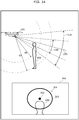
- FIG. 3 illustrates an imaging range of the camera of the unmanned aircraft, as well as a sound pickup direction of the directional microphone.
- Imaging range 130 is roughly square pyramidal and has an apex at a position of camera 103, for example.
- Imaging range 130 is defined by an angular range from range upper limit 131 to range lower limit 132 in horizontal plan view.
- Directional microphone 105 is fixed to airframe 120 to face in sound pickup direction 153 directed obliquely downward by ⁇ degrees from the horizontal direction.
- Sound pickup range 150 of directional microphone 105 is roughly a cone in shape, having sound pickup direction 153 as a central axis and also having an apex at a position of directional microphone 105.
- Sound pickup range 150 is defined by an angular range from range upper limit 151 to range lower limit 152 in horizontal plan view. In horizontal plan view, the angular range of sound pickup range 150 may be narrower than an angle of view defining the imaging range of camera 103.
- FIG. 4 is a block diagram illustrating configurations of the unmanned aircraft and the controller according to the embodiment. More specifically, FIG. 4 is a block diagram illustrating hardware configurations of unmanned aircraft 100 and controller 200 as well as functions of processors 101 and 202.
- Unmanned aircraft 100 includes processor 101, sensor 102, camera 103, ranging sensor 104, directional microphone 105, memory 106, communication interface (IF) 107, and four generators 110.
- Processor 101 obtains detection results from various sensors including sensor 102, an image sensor of camera 103, ranging sensor 104, and directional microphone 105 and also obtains a reception result from communication IF 107, for example. In response to the obtained detection results or reception result, processor 101 performs a corresponding process by executing a predetermined program stored in memory 106 or a storage that is not shown. In this case, processor 101 controls at least one of camera 103, communication IF 107, and four generators 110.
- Sensor 102 includes an acceleration sensor, a gyroscope sensor, an atmospheric pressure sensor, a geomagnetic sensor, and a global positioning system (GPS) receiver, for example.
- GPS global positioning system
- the acceleration sensor detects an acceleration of unmanned aircraft 100 for each of three different directions.
- the acceleration sensor is an example of an orientation sensor that detects an orientation of unmanned aircraft 100.
- the gyroscope sensor detects an angular speed for each rotation about three axes along the three different directions of unmanned aircraft 100.
- the gyroscope sensor is an example of the orientation sensor that detects the orientation of unmanned aircraft 100.
- the atmospheric pressure sensor detects an atmospheric pressure of an environment around unmanned aircraft 100.
- the geomagnetic sensor detects a direction in which a base direction of unmanned aircraft 100 is facing.
- the base direction may be a forward direction of unmanned aircraft 100, for example.
- the geomagnetic sensor is an example of the orientation sensor that detects the orientation of unmanned aircraft 100.
- the GPS receiver receives information indicating a position of this GPS receiver from an artificial satellite that includes a GPS satellite. To be more specific, the GPS receiver detects a current position of unmanned aircraft 100.
- the artificial satellite that transmits the information to be received by the GPS receiver is not limited to the GPS satellite, and may be any satellite designed for a global navigation satellite system (GNSS).
- GNSS global navigation satellite system
- Camera 103 is a device that includes an optical system, such as a lens, and the image sensor.
- An orientation of camera 103 relative to airframe 120 may be fixed or changed freely.
- camera 103 may be supported by a gimbal (not shown) that keeps a triaxial orientation of camera 103 constant. Even if the orientation of unmanned aircraft 100 changes, the gimbal maintains a desirable orientation of camera 103 with respect to, for example, a terrestrial coordinate system.
- the desirable orientation may be defined by an imaging direction of camera 103 that is included in the operation signal received from controller 200.
- Ranging sensor 104 detects a distance between ranging sensor 104 and a near subject.
- ranging sensor 104 may be provided for each pixel of the image sensor of camera 103.
- camera 103 is a depth camera, for example.
- Ranging sensor 104 may be an ultrasonic sensor, a time-of-flight (TOF) camera, or a light detection and ranging (LIDAR) sensor.
- TOF time-of-flight
- LIDAR light detection and ranging
- Directional microphone 105 has a property of being able to pick up higher-quality sound within a sound pickup range having a predetermined angular range with respect to a specific direction (hereinafter, this direction is referred to as the sound pickup direction) than within an angular range outside the sound pickup range.
- the predetermined angular range is 90 degrees or less, and is a three-dimensional angular range extending from a position of directional microphone 105.
- the three-dimensional angular range is roughly a cone in shape, centering on the sound pickup direction and increasing in diameter as a distance from the position of directional microphone 105 increases.
- Directional microphone 105 may be a microphone array including a plurality of microphone elements.
- Directional microphone 105 picks up sound to generate sound data and then outputs the generated sound data.
- Memory 106 stores, for example: information indicating a position and an orientation of camera 103 with respect to airframe 120 of unmanned aircraft 100; information indicating a position and an orientation of directional microphone 105 with respect to airframe 120; information indicating a sound pickup direction, a sound pickup range, and a sound-pickup recommended distance of directional microphone 105; and information indicating a position and an orientation of ranging sensor 104 with respect to airframe 120.
- Memory 106 may store a program to be executed by processor 101.
- Memory 106 is implemented by a nonvolatile memory, for example.
- Communication IF 107 is a communication interface that communicates with controller 200 or a communication terminal. Communication IF 107 includes a communication interface for receiving a transmission signal from controller 200, for example. Communication IF 107 may be a wireless local area network (LAN) interface that meets IEEE 802. 11a, 11b, 11g, 11n, 11ac, and 11ax standards, or may be an interface that meets Bluetooth (registered trademark) standard, for example.
- LAN wireless local area network
- Processor 101 includes functional components including flight controller 101a, image obtainer 101b, and sound picker 101c. More specifically, each of functions performed by flight controller 101a, image obtainer 101b, and sound picker 101c is implemented by processor 101 executing a program stored in memory 106.
- Flight controller 101a controls the number of revolutions of actuator 112 of generator 110, based on: the current position, a flight speed, and a flight orientation of unmanned aircraft 100 that are detected by sensor 102; and an operation signal received by communication IF 107 from controller 200.
- flight controller 101a controls a flight state of unmanned aircraft 100. More specifically, controller 101a controls the flight state of unmanned aircraft 100 according to the operation signal outputted from controller 200 in response to an operation performed on controller 200 by the user. In other words, flight controller 101a functions as a flight controller, for example.
- Image obtainer 101b obtains a captured image captured by camera 103. Image obtainer 101b sequentially obtains the captured image from camera 103 in a first sampling cycle. Here, image obtainer 101b may associate the captured image with a timing at which this captured image is captured by camera 103. Moreover, image obtainer 101b obtains a measured distance measured by ranging sensor 104 from unmanned aircraft 100 to a subject near unmanned aircraft 100. Image obtainer 101b sequentially obtains the measured distance from ranging sensor 104 in a second sampling cycle. Here, image obtainer 101b may associate the measured distance with a timing at which this measured distance is measured by ranging sensor 104.
- Image obtainer 101b associates the captured image with the measured distance in accordance with the captured image and the measured distance that are obtained at the timings corresponding to each other. To be more specific, image obtainer 101b associates a region, which is among a plurality of regions on the captured image, with a measured distance to a subject captured in the region.
- the plurality of regions on the captured image may be a plurality of pixels included in the captured image, or a plurality of blocks included in the captured image.
- the first sampling cycle and the second sampling cycle have the same sampling cycle and the sampling timings match between these cycles.
- the measured distance associated with the corresponding pixel of the captured image is obtained. This allows the captured image and the measured distance to be easily associated with each other using the captured image and the measured distance.
- image obtainer 101b may associate a captured image captured by camera 103 with a measured distance that is measured by ranging sensor 104 at the timing closest to the timing at which this captured image is captured, for example. Note that this is not intended to be limiting if the first sampling cycle and the second sampling cycle synchronize with each other. In this case, the captured image captured by camera 103 is associated with the measured distance measured by ranging sensor 104 at the synchronized timing.
- Image obtainer 101b associates the captured image with the measured distance, based on the captured image captured by camera 103, the measured distance to the subject measured by ranging sensor 104, the information stored in memory 106 to indicate the position and the orientation of camera 103, and the information stored in memory 106 to indicate the position and the orientation of ranging sensor 104.
- Image obtainer 101b outputs a distance image, which is a result of associating the captured image with the measured distance, to controller 200 via communication IF 107.
- Image obtainer 101b may sequentially generate the distance image using the captured image and the measured distance obtained sequentially, and then sequentially output the sequentially generated distance image to controller 200. This enables unmanned aircraft 100 to output the distance image to controller 200 in real time.
- image obtainer 101b may further associate the distance image with the timing at which the captured image, based on which the distance image is generated, is captured by camera 103. Moreover, the captured image obtained by image obtainer 101b from camera 103 may be stored into memory 106. The measured distance obtained by image obtainer 101b may be stored into memory 106. Furthermore, the distance image indicating the result of the association established by image obtainer 101b may be stored into memory 106.
- Sound picker 101c executes a sound pickup process using directional microphone 105 to obtain sound data sequentially generated by directional microphone 105, according to a sound pickup instruction received by communication IF 107 from controller 200. Sound picker 101c may associate the sound data with a timing at which this sound data is generated by directional microphone 105. The sound data obtained by sound picker 101c may be stored into memory 106 or outputted to controller 200 via communication IF 107.
- Controller 200 includes input interface (IF) 201, processor 202, memory 203, display 204, and communication interface (IF) 205. Controller 200 is an example of an information processing device.
- Input IF 201 receives an operation from the user and outputs an operation signal based on the received operation to processor 202.
- Input IF 201 receives an operation related to movement of unmanned aircraft 100 from the user.
- the operation related to movement of unmanned aircraft 100 includes an instruction indicating a direction in which unmanned aircraft 100 is to move and a movement speed in this direction, for example. This operation causes unmanned aircraft 100 to move in the specified direction at the specified movement speed.
- the operation related to movement of unmanned aircraft 100 may include an instruction indicating a direction in which unmanned aircraft 100 is to move and a movement distance in this direction, for example.
- input IF 201 is a control pad that includes: arrow keys or a lever to receive an operation indicating a direction in which unmanned aircraft 100 is to move or indicating rotation of unmanned aircraft 100; and buttons to receive operations to achieve various functions.
- Processor 202 obtains the operation signal based on the operation received by input IF 201 and also obtains a reception result from communication IF 205, for example. In response to the obtained operation signal or reception result, processor 202 performs a corresponding process by executing a predetermined program stored in memory 203 or a storage that is not shown. In this case, processor 202 controls at least one of display 204 and communication IF 205.
- Memory 203 stores programs to be executed by processor 202. Moreover, memory 203 stores the distance image and the sound data that are outputted from unmanned aircraft 100 and obtained via communication IF 205. Furthermore, memory 203 may store, for example: information indicating a position and an orientation of camera 103 with respect to airframe 120 of unmanned aircraft 100; information indicating a position and an orientation of directional microphone 105 with respect to airframe 120; information indicating a sound pickup direction, a sound pickup range, and a sound-pickup recommended distance of directional microphone 105; and information indicating a position and an orientation of ranging sensor 104 with respect to airframe 120. Memory 203 may obtain these sets of information from unmanned aircraft 100 via communication IF 205 and store these obtained sets of information. Memory 203 is implemented by a nonvolatile memory, for example.
- Display 204 displays the captured image outputted by processor 202.
- Display 204 is an example of a display device.
- display 204 is implemented by a liquid crystal display or an organic electroluminescence (EL) display.
- EL organic electroluminescence
- Communication IF 205 is a communication interface that communicates with unmanned aircraft 100.
- Communication IF 205 includes a communication interface for transmitting a transmission signal to unmanned aircraft 100 and a communication interface for receiving a transmission signal from unmanned aircraft 100, for example.
- Communication IF 205 may be a wireless local area network (LAN) interface that meets IEEE 802. 11a, 11b, 11g, 11n, 11ac, and 11ax standards, or may be an interface that meets Bluetooth (registered trademark) standard, for example.
- LAN wireless local area network
- Processor 202 includes functional components including direction converter 202a and image processor 202b. More specifically, each of functions performed by direction converter 202a and image processor 202b is implemented by processor 202 executing a program stored in memory 203.
- FIG. 5 illustrates a conversion operation performed by the direction converter when a sound pickup process is executed.
- FIG. 6 illustrates a process performed to decompose an instruction for speed in the sound pickup direction, into a vertical movement component and a forward-backward movement component.
- direction converter 202a obtains an operation signal from input IF 201. Then, direction converter 202a substitutes a speed instruction for a movement speed in the forward-backward direction that is included in the operation indicated by the user in the operation signal, by a speed instruction for a movement speed in sound pickup direction 153 of directional microphone 105. Then, direction converter 202a controls the movement of unmanned aircraft 100 based on a result of associating the movement direction of unmanned aircraft 100 with sound pickup direction 153 of directional microphone 105.
- direction converter 202a may associate the movement direction of unmanned aircraft 100 with sound pickup direction 153 in accordance with an angular difference between the sound pickup direction of directional microphone 105 and the forward-backward direction (that is, the horizontal direction) of unmanned aircraft 100.
- direction converter 202a decomposes the substituted speed instruction for the movement speed in the sound pickup direction, into a movement speed component in the horizontal direction and a movement speed component in the vertical direction in accordance with an association in which the sound pickup direction is oriented downward by angle ⁇ from the horizontal direction as illustrated in FIG. 6 .
- direction converter 202a generates the decomposed movement speed component in the horizontal direction as the speed instruction for the movement speed of unmanned aircraft 100 in the forward-backward direction.
- direction converter 202a adds the decomposed movement speed component in the vertical direction to the movement speed in the vertical direction that is included in the operation indicated by the operation signal.
- direction converter 202a generates the movement speed obtained as a result of the addition, as the speed instruction for the movement speed in the vertical direction.
- direction converter 202a performs the movement speed addition, where an upward-movement speed in the vertical direction is positive and a downward-movement speed in the vertical direction is negative.
- direction converter 202a outputs a speed instruction for the movement speed in a right-left direction and a speed instruction for a rotational movement speed, without any change.
- direction converter 202a controls the movement of unmanned aircraft 100 by converting the inputted operation in accordance with the result of the association.
- unmanned aircraft 100 can be moved easily in the sound pickup direction as the forward-backward direction. This enables the user to easily perform an operation to move unmanned aircraft 100 close to or away from the sound source.
- directional microphone 105 is fixed to face forward of unmanned aircraft 100 when unmanned aircraft 100 is viewed from above.
- direction converter 202a substitutes the speed instruction for the movement speed in the forward-backward direction by the speed instruction for the movement speed in sound pickup direction 153.
- this is not intended to be limiting.
- direction converter 202a may substitute the speed instruction for the movement speed in the forward-backward direction, which is included in the operation of the user obtained from input IF 201, by the speed instruction for the movement speed in the sound pickup direction.
- direction converter 202a may substitute the speed instruction for the movement speed in the right-left direction by a speed instruction for a movement speed in a direction perpendicular to the sound pickup direction on a horizontal plane.
- the speed instruction for the movement speed in the forward-backward direction is decomposed into movement speed components in the forward-backward, vertical, and right-left directions of unmanned aircraft 100.
- the speed instruction for the movement speed in the right-left direction is decomposed into movement speed components in the forward-backward and right-left directions.
- the decomposed components for the movement speed in the vertical direction are combined into a speed instruction for the vertical direction.
- the decomposed components for the movement speed in the forward-backward direction are combined into a speed instruction for the forward-backward direction.
- the decomposed components for the movement speed in the right-left direction are combined into a speed instruction for the right-left direction.
- the direction indicated by the speed instruction to be substituted by the speed instruction for the movement speed in sound pickup direction 153 may be determined according to the imaging direction of camera 103. For example, when the imaging direction of camera 103 is forward, the speed instruction for the forward-backward direction may be substituted by the speed instruction for sound pickup direction 153. When the imaging direction of camera 103 is on the right, the speed instruction for the right-left direction may be substituted by the speed instruction for sound pickup direction 153.
- a sound pickup direction by which the speed instruction for the movement speed in the forward-backward direction is substituted may be determined according to the imaging direction of camera 103. For example, if the imaging direction of camera 103 is forward, the speed instruction for the forward-backward direction may be substituted by the speed instruction for the sound pickup direction of a directional microphone disposed to face forward. If the imaging direction of camera 103 is on the right, the speed instruction may be substituted by the speed instruction for the sound pickup direction of a directional microphone disposed to face to the right.
- the operation signal outputted from input IF 201 is outputted, without conversion, to unmanned aircraft 100 via communication IF 205.
- unmanned aircraft 100 is controlled to move in the specified direction at the specified movement speed according to the operation signal.
- Image processor 202b obtains the distance image, the sound data, the position and the orientation of camera 103, and the position and the orientation of directional microphone 105, from memory 203. Image processor 202b calculates sound pickup direction 153 of directional microphone 105 using the position and the orientation of camera 103 and the position and the orientation of directional microphone 105.
- image processor 202b also obtains, from memory 203, the measured distance to the subject captured in the captured image using the obtained distance image. Image processor 202b further calculates sound pickup range 150 of directional microphone 105 at the position of the subject captured in the captured image, using sound pickup direction 153 calculated and the measured distance obtained.
- image processor 202b superimposes object 311 including object 312 indicating sound pickup direction 153 and object 313 indicating sound pickup range 150, on captured image 310 of the distance image at the position corresponding to sound pickup direction 153 calculated.
- object 312 indicates a base direction in which directional microphone 105 picks up sound.
- image processor 202b calculates object 312 and object 313 in accordance with sound pickup range 150 and a distance to a subject captured in captured image 310.
- Image processor 202b reads the sound pickup range of directional microphone 105 from memory 203.
- image processor 202b determines sound pickup range 150 of directional microphone 105 on captured image 310.
- Image processor 202b uses the obtained distance image to calculate a distance to a nearest subject present in sound pickup range 150 determined, and calculates object 312 and object 313 corresponding to the calculated distance.
- image processor 202b divides the distance image into a plurality of areas and calculates a distance for each of the plurality of areas. Then, image processor 202b calculates, as object 312 and object 313, an object corresponding to a distance that satisfies a predetermined condition among a plurality of distances calculated for the plurality of areas in sound pickup range 150.
- Object 313 is oval, for example.
- the distance that satisfied the predetermined condition among the plurality of distances may be the shortest distance or a distance calculated most often. Alternatively, this distance may be calculated based on the distance range in which a largest number of distances are distributed. Moreover, an object corresponding to a specific distance in sound pickup range 150 may be calculated based on sizes of imaging range 130 and sound pickup range 150 or a positional relationship between imaging range 130 and sound pickup range 150 at a position that is the specific distance away from unmanned aircraft 100.
- object 313 may be calculated based on the sizes of imaging range 130 and sound pickup range 150 or the positional relationship between imaging range 130 and sound pickup range 150 in a section plane roughly perpendicular to the imaging direction or sound pickup direction 153 at the position that is the specific distance away from unmanned aircraft 100.
- the distance for each area may be a representative value, such as an average value or a median value, of a plurality of distances measured for a plurality of pixels in this target area. Alternatively, the distance may be the plurality of distances themselves measured for the plurality of pixels. If ranging sensor 104 includes a different sensor instead of a depth camera, ranging sensor 104 may divide imaging range 130 of camera 103 into a plurality of areas in a plane crossing an optical axis of camera 103 and calculate a distance to a subject for each of these divided areas. In this case, unmanned aircraft 100 transmits the captured image captured by camera 103 and a plurality of distances measured for the plurality of areas on the captured image.
- image processor 202b may first determine a position of object 312 on the image and then generate an object, as object 313, corresponding to the distance to the subject captured in the determined position.
- ranging sensor 104 may measure a distance to the subject in sound pickup direction 153.
- Object 313 is oval, for example. In this case, if sound source 400 is present in sound pickup range 150 but sound pickup direction 153 deviates from sound source 400, a distance from unmanned aircraft 100 to a subject farther away than sound source 400 is measured as illustrated in FIG. 14 described later.
- image processor 202b may determine for each pixel whether the pixel is within sound pickup range 150, using sound pickup range 150 associated with captured image 310 and distance information for each pixel in the distance image. Then, image processor 202b may calculate, as object 313, the area of the pixel present within (or on a boundary of) sound pickup range 150. Similarly, image processor 202b may determine for each pixel whether the pixel is in a position corresponding to sound pickup direction 153. Then, image processor 202b may calculate object 312 so that object 312 is displayed on the pixels present in sound pickup direction 153. In this case, object 313 calculated is unlikely to have a smooth curve because the distance is different for each pixel. However, the sound pickup range is displayed more accurately. If sound pickup range 150 extends over a plurality of subjects, object 313 may be displayed differently for each of the distances to the subjects.
- the subject captured in captured image 310 is a person as an example of the sound source.
- FIG. 7 illustrates an example of the image capturing a person as the sound source.
- FIG. 8 illustrates an example of the captured image on which the object is superimposed.
- the user operating the unmanned aircraft determines whether a subject captured in captured image 310 is a sound source and that the user orients the sound pickup direction toward the sound source determined as being a sound pickup target by the user. For this reason, presentation-manner control according to the present embodiment may be understandably performed on a subject that is not a sound source.
- the unmanned aircraft may determine whether a subject captured in captured image 310 is a sound source. If the subject is determined as being the sound source, image processor 202b may perform the presentation-manner control and direction converter 202a may perform the direction conversion process according to the present embodiment.
- image processor 202b recognizes a subject captured in captured image 310 through image analysis of captured image 310 and determines whether the recognized subject is a sound source. If the recognized subject is determined as being the sound source, image processor 202b performs the presentation-manner control and direction converter 202a performs the direction conversion process for the operation.
- image processor 202b may perform the presentation-manner control and direction converter 202a may perform the direction conversion process according to the present embodiment.
- unmanned aircraft 100 determines whether a distance between a subject, which is a sound source, and unmanned aircraft 100 is a predetermined distance or less. If the distance is determined as being the predetermined distance or less, image processor 202b may perform the presentation-manner control and direction converter 202a may perform the direction conversion process according to the present embodiment.
- Image processor 202b outputs captured image 314 on which object 311 is superimposed (hereinafter, the image as a result of the superimposition is referred to as the superimposed image) to display 204.
- display 204 displays superimposed image 314.
- FIG. 9 illustrates a positional relationship between the unmanned aircraft and the sound source, as well as a superimposed image, in a first situation.
- FIG. 10 illustrates a positional relationship between the unmanned aircraft and the sound source, as well as a superimposed image in a second situation.
- FIG. 11 illustrates a positional relationship between the unmanned aircraft and the sound source, as well as a superimposed image in a third situation.
- FIG. 12 illustrates a positional relationship between the unmanned aircraft and the sound source, as well as a superimposed image, in a fourth situation.
- FIG. 13 illustrates a positional relationship between the unmanned aircraft and the sound source, as well as a superimposed image, in a fifth situation.
- FIG. 10 illustrates a positional relationship between the unmanned aircraft and the sound source, as well as a superimposed image in a second situation.
- FIG. 11 illustrates a positional relationship between the unmanned aircraft and the sound source, as well as a superimposed image in a third situation.
- FIG. 14 illustrates a positional relationship between the unmanned aircraft and the sound source, as well as a superimposed image, in a sixth situation.
- FIG. 15 illustrates a positional relationship between the unmanned aircraft and the sound source, as well as a superimposed image, in a seventh situation.
- FIG. 16 illustrates a positional relationship between the unmanned aircraft and the sound source, as well as a superimposed image, in an eighth situation.
- FIG. 9 to FIG. 11 and FIG. 14 to FIG. 16 are side views of the unmanned aircraft.
- FIG. 12 and FIG. 13 are top views of the unmanned aircraft.
- the first situation is similar to the situations illustrated in FIG. 3 and FIG. 8 . Thus, description of this situation is omitted here.
- unmanned aircraft 100 has ascended from the position in the first situation.
- imaging range 130 and sound pickup range 150 move over sound source 400 as a result of the ascent of unmanned aircraft 100.
- sound source 400 captured is located lower in superimposed image 324 as compared to sound source 400 in superimposed image 314 in the first situation.
- Unmanned aircraft 100 does not move in the horizontal nor forward-backward direction, and thus object 311 is superimposed in superimposed image 324 without any change from the first situation.
- unmanned aircraft 100 has moved from the position in the first situation to approach sound source 400 in the horizontal direction, or more specifically, unmanned aircraft 100 has moved forward.
- imaging range 130 and sound pickup range 150 change with respect to sound source 400 as a result of the forward movement of unmanned aircraft 100.
- sound source 400 captured is larger in superimposed image 334 as compared to sound source 400 in superimposed image 314 in the first situation.
- object 333 indicating sound pickup range 150 in object 331 is calculated to increase in size with the size increase of sound source 400.
- an area of sound pickup range 150 on sound source 400 decreases with decreasing distance to sound source 400.
- object 313 on superimposed image 314 and object 333 on superimposed image 334 are not so different in size.
- object 332 indicating sound pickup direction 153 does not change in orientation with respect to camera 103 and thus points to the same position as object 312.
- the fourth situation is an example in which camera 103 is rotatably connected to airframe 120 and captures an image in a left angular range instead of the forward range of unmanned aircraft 100.
- sound pickup range 150 is included in imaging range 130 and sound source 400 is outside sound pickup range 150.
- object 341 including object 342 indicating sound pickup direction 153 and object 343 indicating sound pickup range 150 is superimposed at a position where object 341 is not overlaid on sound source 400 captured in superimposed image 344. This allows the user to easily orient sound pickup range 150 of directional microphone 105 toward sound source 400 without changing the imaging range of camera 103 by performing an operation on controller 200 to move unmanned aircraft 100 in a counterclockwise direction or to the left.
- the fifth situation is an example in which camera 103 is rotatably connected to airframe 120 as in the fourth situation and captures an image in a more left angular range as compared to the fourth situation.
- sound pickup range 150 is shifted to the right from imaging range 130.
- image processor 202b generates superimposed image 354 in which object 351 pointing toward sound pickup direction 153 from imaging range 130 is superimposed.
- Object 351 is a triangle pointing to the right, for example. To be more specific, object 351 indicates that sound pickup range 150 of directional microphone 105 is on the right.
- Object 351 may be a rightward arrow.
- Object 351 is superimposed in a region near a side that is closer to the indicated direction on the captured image. As in the fourth situation, this allows the user to easily orient sound pickup range 150 of directional microphone 105 toward sound source 400 without changing the imaging range of camera 103 by performing the operation on controller 200 to move unmanned aircraft 100 in the counterclockwise direction or to the left.
- object 351 indicates a direction in which sound pickup direction 153 of directional microphone 105 is closer.
- the presentation-manner control is performed for an object according to a distance from unmanned aircraft 100 to sound source 400 when sound source 400 is in sound pickup range 150 of directional microphone 105.
- sound source 400 is in sound pickup range 150 of directional microphone 105 and also in a first range of first distance d1 in which the sound pickup quality of directional microphone 105 is highest, that is, a first quality.
- the first range has first distance d1 measured from the position of directional microphone 105 as the starting point, for example.
- image processor 202b generates superimposed image 364 in which object 361 is presented with the first quality, according to a difference between first distance d1 and a measured distance from unmanned aircraft 100 to sound source 400.
- image processor 202b uses a thick line to present object 363, which indicates the sound pickup range in object 361.
- sound source 400 is in sound pickup range 150 of directional microphone 105 and also in a second range of second distance d2 in which the sound pickup quality of directional microphone 105 is second highest, that is, a second quality.
- the second range is, for example, a range between the position having first distance d1 measured from the starting point and the position having second distance d2 measured from the starting point when the starting point is the position of directional microphone 105.
- image processor 202b generates superimposed image 374 in which object 371 is presented with the second quality, according to a difference between second distance d2 and a measured distance from unmanned aircraft 100 to sound source 400.
- image processor 202b uses a double line to present object 373, which indicates the sound pickup range in object 371.
- sound source 400 is in sound pickup range 150 of directional microphone 105 and also in a third range, farther than second distance d2, in which the sound pickup quality of directional microphone 105 is low, that is, a third quality.
- the third range is farther than the second range of second distance d2 measured from the position of directional microphone 105 as the starting point, for example.
- image processor 202b generates superimposed image 384 in which object 381 is presented with the third quality, according to a difference between second distance d2 and a measured distance from unmanned aircraft 100 to sound source 400.
- image processor 202b uses a broken line to present object 383, which indicates the sound pickup range in object 381.
- image processor 202b may maintain the presentation manner of the object without any change. Moreover, the presentation manner of the object may be maintained based on, instead of the sound pickup quality, whether any subject is present in a range where the measured distance is measurable. For example, if directional microphone 105 and camera 103 are assumed to be sufficiently close to each other, positions and sizes of objects 382 and 383 on the image do not significantly change with respect to a distance to the subject of object 382. Thus, when the subject is outside the range of the ranging sensor, image processor 202b calculates and displays the positions and sizes of objects 382 and 383 on the assumption that the subject is at a maximum measurable distance of the ranging sensor.
- image processor 202b may perform the presentation-manner control for the object according to the distance from unmanned aircraft 100 to sound source 400 as in the sixth to eighth situations described above.
- Subject 500 other than sound source 400 is in sound pickup range 150 in the fourth situation.
- subject 500 is a signboard.
- image processor 202b does not change the presentation manner of object 343. More specifically, if subject 500 present outside sound pickup range 150 enters sound pickup range 150, image processor 202b superimposes object 343 on the captured image without changing the presentation manner used before subject 500 enters sound pickup range 150. Thus, even if the distance from unmanned aircraft 100 to subject 500 in sound pickup range 150 is within the third range farther than the range of second distance d2, image processor 202b does not change the presentation manner to the manner used when sound source 400 is in the third range.
- whether the subject is a sound source is determined through image analysis of the captured image for example, as described above.
- image processor 202b may maintain an initial presentation manner to present object 343. Thus, in the fourth situation, image processor 202b superimposes object 343 on the captured image in the initial presentation manner.
- image processor 202b changes the presentation manner according to the sound pickup quality by changing the line styles in the sixth to eight situations. Instead of changing the line style of an object indicating the sound pickup range, image processor 202b may change the presentation manner by changing a color of the object or by changing density of the color of the object. Alternatively, instead of changing the presentation manner of the object indicating the sound pickup range, image processor 202b may change the presentation manner of the object indicating the sound pickup direction. For example, image processor 202b may change the object indicating the sound pickup direction in size, or may cause the object to blink and then change a blinking rate.
- image processor 202b may generate a superimposed image on which a warning sign has been superimposed and then display the generated superimposed image on display 204.
- the object indicating the sound pickup range is presented by the line.
- this is not intended to be limiting. Different shades of color may be used to distinguish between inside and outside of the sound pickup range on the image.
- the following describes an operation performed by unmanned aircraft 100 and controller 200 according to the embodiment. An example of an operation performed in the sound pickup process is first described.
- FIG. 17 is a sequence illustrating the example of the operation performed by the unmanned aircraft and the controller in the sound pickup process according to the embodiment.
- Image obtainer 101b of unmanned aircraft 100 obtains a captured image from camera 103 and obtains a measured distance from ranging sensor 104 (S11).
- image obtainer 101b generates a distance image using the captured image obtained and the measured distance obtained (S12).
- steps S11 and S12 are described in detail in the above description on the function of image obtainer 101b and thus omitted here.
- Sound picker 101c obtains sound data sequentially generated by directional microphone 105 (S13).
- the process in step S13 is described in detail in the above description on the function of sound picker 101c and thus omitted here.
- Processor 101 transmits the distance image generated and the sound data generated, to controller 200 via communication IF 107 (S14).
- processor 101 may transmit, to controller 200 via communication IF 107, the information stored in memory 106 to indicate the position and orientation of camera 103 and the information stored in memory 106 to indicate the position, orientation, and sound pickup direction of directional microphone 105.
- controller 200 executes the image processing (S15).
- the image processing is described in detail with reference to FIG. 18 .
- FIG. 18 is a flowchart illustrating details of the image processing performed by the controller according to the embodiment.
- Image processor 202b of controller 200 obtains the information indicating the position and orientation of camera 103 and the information indicating the position, orientation, and sound pickup direction of directional microphone 105 (S21).
- Image processor 202b may obtain the aforementioned information from unmanned aircraft 100 via communication IF 107. Alternatively, if the aforementioned information is previously stored in memory 203, image result 202b may obtain the aforementioned information from memory 203.
- image processor 202b calculates a position corresponding to the sound pickup direction on the captured image in the obtained distance image (S22) .
- Image processor 202b superimposes an object indicating the sound pickup direction, at the position corresponding to the calculated sound pickup direction on the captured image (S23).
- the processes in steps S21 and S23 are described in detail in the above description on the function of image processor 202b and thus omitted here.
- processor 202 displays the superimposed image generated in the image processing on display 204 (S16).
- FIG. 19 is a sequence illustrating an example of an operation performed by the unmanned aircraft and the controller in the operation conversion process of the unmanned aircraft according to the embodiment.
- Direction converter 202a of controller 200 obtains the sound pickup direction of directional microphone 105 of unmanned aircraft 100 (S31).
- Direction converter 202a may obtain the aforementioned sound pickup direction from unmanned aircraft 100 via communication IF 107.
- direction converter 202a may obtain the aforementioned sound pickup direction from memory 203.
- Direction converter 202a receives, from input IF 201, an operation in which the obtained sound pickup direction is the forward-backward direction (S32).
- Direction converter 202a converts the operation into an operation signal instructing unmanned aircraft 100 to move in the corresponding direction (S33). Then, direction converter 202a outputs the converted operation signal to unmanned aircraft 100 via communication IF 206 (S34).
- steps S31 and S33 are described in detail in the above description on the function of direction converter 202a and thus omitted here.
- Unmanned aircraft 100 performs the flight control according to the operation signal received (S35).
- Controller 200 causes display 204 to display superimposed image 314 on which object 311 indicating sound pickup direction 153 of directional microphone 105 is superimposed at the position corresponding to calculated sound pickup direction 153 on the captured image outputted from camera 103 of unmanned aircraft 100.
- the user is able to find the position of sound pickup direction 153 of directional microphone 105 on superimposed image 314. More specifically, sound pickup direction 153 of directional microphone 105 can be visualized.
- the user is able to easily orient sound pickup direction 153 of directional microphone 105 toward sound source 400 by operating unmanned aircraft 100 to align object 311 with the sound source of the target sound. This enhances the quality of sound picked up using unmanned aircraft 100 operated by a person.
- Image processor 202b of controller 200 further obtains a measured distance measured to a subject captured in the captured image, further calculates sound pickup range 150 of directional microphone 105 at a position of the subject using the sound pickup direction calculated and the measured distance obtained, and superimposes object 313 indicating calculated sound pickup range 150 on the captured image.
- Direction converter 202a of controller 200 establishes an association between a movement direction of unmanned aircraft 100 and sound pickup direction 153, and controls movement of unmanned aircraft 100 based on a result of the association.
- the movement of unmanned aircraft 100 is controlled in a direction with respect to the sound pickup direction. This enables unmanned aircraft 100 to move while keeping sound pickup direction 153 of directional microphone 105 toward sound source 400.
- Direction converter 202a of controller 200 receives an operation input relating to the movement of unmanned aircraft 100, and controls the movement of unmanned aircraft 100 by converting the operation input based on the result of the association.
- the user is able to easily move unmanned aircraft 100 in a direction with respect to the sound pickup direction. This enables the user to move unmanned aircraft 100 while keeping sound pickup direction 153 of directional microphone 105 toward sound source 400.
- image processor 202b of controller 200 When sound pickup direction 153 calculated is outside imaging range 130 of camera 103, image processor 202b of controller 200 according to the present embodiment superimposes, on the captured image, object 351 pointing toward sound pickup direction 153 from imaging range 130. Thus, while viewing superimposed image 314 displayed, the user is able to easily orient sound pickup direction 153 of directional microphone 105 toward sound source 400 by operating unmanned aircraft 100 so that unmanned aircraft 100 is oriented in the direction indicated by object 351. This enhances the quality of sound pickup.
- Image processor 202b of controller 200 further obtains a setting distance corresponding to quality of sound pickup of directional microphone 105, and controls a presentation manner of the object based on a difference between the measured distance obtained to the subject in the captured image and the setting distance obtained.
- the object can be displayed in the presentation manner that is different depending on whether the quality of sound pickup is assumed to be high or low according to the distance from the subject, which is sound source 400, to directional microphone 105.
- the user while viewing the superimposed image displayed, the user is able to operate unmanned aircraft 100 so that the object is displayed in the presentation manner with the high quality. This enhances the quality of sound pickup for the target sound obtained from directional microphone 105.
- Image processor 202b of controller 200 maintains the presentation manner of the object when the difference is greater than or equal to a threshold value. If the quality of sound pickup is a predetermined quality or lower, the presentation manner of the object is maintained. This can reduce a processing load of changing the presentation manner.
- Controller 200 may selectively display or not display an object indicating the sound pickup direction or the sound pickup range of directional microphone 105, according to an operation received from the user.
- controller 200 controls the movement of unmanned aircraft 100 by converting the inputted operation based on the result of the association so that unmanned aircraft 100 moves in the sound pickup direction of directional microphone 105.
- Controller 200 may be allowed to disable the aforementioned conversion so that normal movement control is performed on unmanned aircraft 100 even if unmanned aircraft 100 is operated during the sound pickup process.
- the above embodiment describes an example in which the object that is an oval frame is superimposed.
- the object may be a filled oval or an oval with the outside filled.
- image processor 202b of controller 200 may generate a superimposed image on which the position of the sound source on the captured image that is determined based on the result outputted from the microphone array is superimposed. Then, the superimposed image generated may be displayed on display 204.
- Controller 200 may recognize a shape of a person captured in the captured image through image recognition, and locate a mouth in the recognized shape of the person. Then, controller 200 may generate a superimposed image in which an object indicating the sound source is superimposed at a position of the located mouth of the person. Moreover, the superimposed image generated may be displayed on display 204.
- Unmanned aircraft 100 includes four generators 110.
- the number of generators included in unmanned aircraft 100 is not limited to four.
- the number of generators may be one to three, or at least five.
- Unmanned aircraft 100 includes airframe 120 that is connected to four generators 110 via four arms 121. However, this is not intended to be limiting. Four arms 121 may not be included if four generators 110 are connected to airframe 120. To be more specific, unmanned aircraft 100 may include four generators 110 directly connected to airframe 120.
- Unmanned aircraft 100 includes one directional microphone 105.
- the number of directional microphones included in unmanned aircraft 100 is not limited to one and may be two or more. If the unmanned aircraft includes two or more directional microphones, the process of calculating the sound pickup direction of a directional microphone may be similarly performed for each of the two or more directional microphones. If the unmanned aircraft includes the two or more directional microphones in this way, an object indicating the sound pickup direction may be displayed for each of the directional microphones. This object may be displayed together with an identifier indicating the sound pickup direction of which one of the two or more directional microphones.
- controller 200 includes image processor 202b.
- Unmanned aircraft 100 may have the same function as image processor 202b. More specifically, unmanned aircraft 100 may generate a superimposed image and transmit the superimposed image generated to controller 200. In this case, controller 200 displays the superimposed image received from unmanned aircraft 100 on display 204.
- Each of the components in the above embodiment may be configured with dedicated hardware or may be implemented by executing a software program suitable for the component.
- Each of the components may be implemented by a program executer, such as a CPU or a processor, reading and executing a software program recorded on a hard disk or a recording medium, such as a semiconductor memory.
- software that implements, for example, controller 200 and the information processing method according to the above embodiment is the following program.
- this program is an information processing method executed by at least one information processing device including a processor and a memory.
- the information processing method includes: storing, into the memory, a captured image outputted from a camera included in an unmanned aircraft and a sound outputted from a directional microphone included in the unmanned aircraft; storing, into the memory, a position and an orientation of the camera and a position and an orientation of the directional microphone; obtaining, from the memory, the captured image, the sound, the position and the orientation of the camera, and the position and the orientation of the directional microphone; calculating a sound pickup direction of the directional microphone using the position and the orientation of the camera and the position and the orientation of the directional microphone; superimposing an object indicating the sound pickup direction at a position, on the captured image, corresponding to the sound pickup direction calculated; and causing a display device to display the captured image on which the object is superimposed.
- the sound pickup range of the directional microphone may be variable. If the directivity of the microphone is changed, the sound pickup range based on the changed directivity is obtained, for example. In this case, an object based on the obtained sound pickup range is superimposed.
- machine learning may be used in the processing performed by processor 101 or processor 202.
- Types of machine learning algorithms include, for example: supervised learning algorithms that learn a relationship between an input and an output using training data given a label (output information) associated with input information; unsupervised learning algorithms that find a data structure from only unlabeled inputs; semi-supervised learning that approaches both labeled training data and unlabeled training data; and reinforcement learning algorithms that learn a set of actions leading to the highest reward by receiving feedback (reward) from an action chosen as a result of state observation.
- Specific approaches of machine learning include: a neural network (including deep learning using a multi-layered neural network); genetic programming; decision tree; Bayesian network; and support vector machine (SVM). Any one of the aforementioned specific examples may be used in the present disclosure.
- the present disclosure is useful as an information processing device, an information processing method, and a program that are capable of enhancing the quality of sound picked up using an unmanned aircraft operated by a person.
Landscapes
- Engineering & Computer Science (AREA)
- Physics & Mathematics (AREA)
- Signal Processing (AREA)
- Aviation & Aerospace Engineering (AREA)
- Remote Sensing (AREA)
- Radar, Positioning & Navigation (AREA)
- General Physics & Mathematics (AREA)
- Health & Medical Sciences (AREA)
- Otolaryngology (AREA)
- Acoustics & Sound (AREA)
- Multimedia (AREA)
- Theoretical Computer Science (AREA)
- Computer Vision & Pattern Recognition (AREA)
- Automation & Control Theory (AREA)
- Mechanical Engineering (AREA)
- Circuit For Audible Band Transducer (AREA)
- Studio Devices (AREA)
- Details Of Audible-Bandwidth Transducers (AREA)
- Closed-Circuit Television Systems (AREA)
- Traffic Control Systems (AREA)
- Measurement Of Velocity Or Position Using Acoustic Or Ultrasonic Waves (AREA)
Abstract
Description
- The present disclosure relates to an information processing device, an information processing method, and a program.
- Patent Literature (PTL) 1 discloses a teleoperation system that causes a ground device to display an image, captured by an imaging device mounted on an unmanned helicopter operated by a ground user, on which angle information indicating an orientation of an optical system of the imaging device is superimposed.
- [PTL 1]
Japanese Unexamined Patent Application Publication No. 2001-309233 - Unfortunately, the technology disclosed in
PTL 1 is not intended for an unmanned aircraft with a built-in microphone that obtains sound. Sound cannot be recognized visually. For this reason, even if the image is provided, it is difficult for a person to operate the unmanned aircraft to pick up a target sound of good quality. - In view of this, the present disclosure provides an information processing device, an image processing method, and a program that are capable of improving quality of sound picked up using an unmanned aircraft operated by a person.
- An information processing device according to the present disclosure includes: a processor; and a memory, wherein the memory stores (i) a captured image outputted from a camera included in an unmanned aircraft and (ii) a sound outputted from a directional microphone included in the unmanned aircraft, and stores (i) a position and an orientation of the camera and (ii) a position and an orientation of the directional microphone, and the processor obtains, from the memory, the captured image, the sound, the position and the orientation of the camera, and the position and the orientation of the directional microphone, calculates a sound pickup direction of the directional microphone using the position and the orientation of the camera and the position and the orientation of the directional microphone, superimposes an object indicating the sound pickup direction at a position, on the captured image, corresponding to the sound pickup direction calculated, and causes a display device to display the captured image on which the object is superimposed.
- It should be noted that general or specific aspects of the present disclosure may be implemented to a system, a method, an integrated circuit, a computer program, a computer-readable recording medium such as a Compact Disc-Read Only Memory (CD-ROM), or any given combination thereof.
- The information processing device, the image processing method, and the program according to the present disclosure are capable of improving quality of sound picked up using an unmanned aircraft operated by a person.
-
- [
FIG. 1 ]
FIG. 1 illustrates an external view of an unmanned aircraft and a controller according to an embodiment. - [
FIG. 2 ]
FIG. 2 is a top view of the unmanned aircraft according to the embodiment. - [
FIG. 3 ]
FIG. 3 illustrates an imaging range of a camera of the unmanned aircraft, as well as a sound pickup direction of a directional microphone. - [
FIG. 4 ]
FIG. 4 is a block diagram illustrating configurations of the unmanned aircraft and the controller according to the embodiment. - [
FIG. 5 ]
FIG. 5 illustrates a conversion operation performed by a direction converter when a sound pickup process is executed. - [
FIG. 6 ]
FIG. 6 illustrates a process performed to decompose an instruction for speed in the sound pickup direction, into a vertical movement component and a forward-backward movement component. - [
FIG. 7 ]
FIG. 7 illustrates an example of a captured image of a person as a sound source. - [
FIG. 8 ]
FIG. 8 illustrates an example of a captured image on which an object is superimposed. - [
FIG. 9 ]
FIG. 9 illustrates a positional relationship between the unmanned aircraft and the sound source, as well as a superimposed image, in a first situation. - [
FIG. 10 ]
FIG. 10 illustrates a positional relationship between the unmanned aircraft and the sound source, as well as a superimposed image in a second situation. - [
FIG. 11 ]
FIG. 11 illustrates a positional relationship between the unmanned aircraft and the sound source, as well as a superimposed image in a third situation. - [
FIG. 12 ]
FIG. 12 illustrates a positional relationship between the unmanned aircraft and the sound source, as well as a superimposed image, in a fourth situation. - [
FIG. 13 ]
FIG. 13 illustrates a positional relationship between the unmanned aircraft and the sound source, as well as a superimposed image, in a fifth situation. - [
FIG. 14 ]
FIG. 14 illustrates a positional relationship between the unmanned aircraft and the sound source, as well as a superimposed image, in a sixth situation. - [
FIG. 15 ]
FIG. 15 illustrates a positional relationship between the unmanned aircraft and the sound source, as well as a superimposed image, in a seventh situation. - [
FIG. 16 ]
FIG. 16 illustrates a positional relationship between the unmanned aircraft and the sound source, as well as a superimposed image, in an eighth situation. - [
FIG. 17 ]
FIG. 17 is a sequence illustrating an example of an operation performed by the unmanned aircraft and the controller in the sound pickup process according to the embodiment. - [
FIG. 18 ]
FIG. 18 is a flowchart illustrating details of image processing performed by the controller according to the embodiment. - [
FIG. 19 ]
FIG. 19 is a sequence illustrating an example of an operation performed by the unmanned aircraft and the controller in an operation conversion process of the unmanned aircraft according to the embodiment. - In recent years, a study has been made to use an unmanned aircraft, provided with a propeller to develop a thrust force in flight, as a mobile communication tool to pick up sound. A microphone mounted on such unmanned aircraft picks up not only a target sound, but also noise, mainly wind noise by the propeller, caused by this unmanned aircraft itself. To reduce the noise to be picked up, a directional microphone may be used to pick up sound.
- For the directional microphone mounted on the unmanned aircraft that flies over, it is desirable to be fixed to an airframe of the unmanned aircraft to aim obliquely downward from the airframe. With this, a sound pickup range of the directional microphone is oriented toward a sound source of the target sound. Moreover, in view of reducing the unmanned aircraft in weight, a small number of directional microphones may be mounted. In this case, the sound pickup range of these directional microphones is limited to a specific range. Thus, the airframe is to be moved to a position where the sound source is within the sound pickup range of the directional microphones.
- Here, the technology disclosed in
PTL 1 enables the ground device to display the image, captured by the imaging device, on which the angle information indicating the orientation of the optical system of the imaging device is superimposed. This image displayed together with the angle information enhances operability of the imaging device as well as operability of the mobile vehicle. - However, the technology disclosed in
PTL 1 is not intended for an unmanned aircraft with a built-in microphone that obtains sound. On this account, it is difficult to determine whether a sound source is within a sound pickup range of a directional microphone. It is thus also difficult to move the unmanned aircraft to a position where the sound source is within the sound pickup range of the directional microphone. - In order to solve the above problems, an information processing device according to an aspect of the present disclosure includes: a processor; and a memory, wherein the memory stores (i) a captured image outputted from a camera included in an unmanned aircraft and (ii) a sound outputted from a directional microphone included in the unmanned aircraft, and stores (i) a position and an orientation of the camera and (ii) a position and an orientation of the directional microphone, and the processor obtains, from the memory, the captured image, the sound, the position and the orientation of the camera, and the position and the orientation of the directional microphone, calculates a sound pickup direction of the directional microphone using the position and the orientation of the camera and the position and the orientation of the directional microphone, superimposes an object indicating the sound pickup direction at a position, on the captured image, corresponding to the sound pickup direction calculated, and causes a display device to display the captured image on which the object is superimposed.
- Thus, the display device displays the captured image on which the object indicating the sound pickup direction of the directional microphone is superimposed at the position corresponding to the calculated sound pickup direction on the captured image outputted from the camera of the unmanned aircraft. As a result, the user is able to find the position of the sound pickup direction of the directional microphone on the captured image. More specifically, the sound pickup direction of the directional microphone can be visualized. Thus, while viewing the image displayed on the display device, the user is able to easily orient the sound pickup direction of the directional microphone toward the sound source by operating the unmanned aircraft to align the object with the sound source of the target sound. This enhances the quality of sound picked up using the unmanned aircraft operated by a person.
- It is possible that the processor calculates, as the sound pickup direction, a base direction in which the directional microphone picks up the sound.
- Thus, while viewing the image displayed on the display device, the user is able to easily orient the base direction, in which the directional microphone picks up the sound, toward the sound source by operating the unmanned aircraft to align the object with the sound source. This enhances the quality of sound picked up using the unmanned aircraft operated by a person.
- It is also possible that the processor further obtains a measured distance measured to a subject captured in the captured image, further calculates a sound pickup range of the directional microphone at a position of the subject, using the sound pickup direction calculated and the measured distance obtained, and superimposes an object indicating the sound pickup range calculated, as the object indicating the sound pickup direction, on the captured image.
- Thus, while viewing the image displayed on the display device, the user is able to easily keep the sound source within the sound pickup range of the directional microphone by operating the unmanned aircraft to align the object with the sound source. This enhances the quality of sound picked up using the unmanned aircraft operated by a person.
- It is further possible that the processor establishes an association between a movement direction of the unmanned aircraft and the sound pickup direction, and controls movement of the unmanned aircraft based on a result of the association.
- Thus, the movement of the unmanned aircraft is controlled in a direction with respect to the sound pickup direction. This enables the unmanned aircraft to move while keeping the sound pickup direction of the directional microphone toward the sound source.
- It is still further possible that the processor receives an operation input relating to the movement of the unmanned aircraft, and controls the movement of the unmanned aircraft by converting the operation input based on the result of the association.
- Thus, the user is able to easily move the unmanned aircraft in a direction with respect to the sound pickup direction. This enables the user to move the unmanned aircraft while keeping the sound pickup direction of the directional microphone toward the sound source.
- It is still further possible that when the sound pickup direction calculated is outside an imaging range of the camera, the processor superimposes, on the captured image, an object pointing toward the sound pickup direction from the imaging range.
- Thus, while viewing the image displayed on the display device, the user is able to easily orient the sound pickup direction of the directional microphone toward the sound source by operating the unmanned aircraft to orient the unmanned aircraft in the direction indicated by the object. This enhances the quality of sound pickup.
- It is still further possible that the processor further obtains a setting distance corresponding to quality of sound pickup of the directional microphone, and controls a presentation manner of the object indicating the sound pickup direction in accordance with a difference between the measured distance obtained to the subject in the captured image and the setting distance obtained.
- Thus, the display device is able to display the object in the presentation manner that is different depending on whether the quality of sound pickup is assumed to be high or low according to the distance from the subject to the directional microphone. Thus, while viewing the image displayed on the display device, the user is able to operate the unmanned aircraft so that the object is displayed in the presentation manner with the high quality. This enhances the quality of sound pickup for the target sound obtained from the directional microphone.
- It is still further possible that the processor maintains the presentation manner of the object indicating the sound pickup direction when the difference is greater than or equal to a threshold value or when a subject is not present in a range where the measured distance is measurable.
- If the quality of sound pickup is a predetermined quality or lower, the presentation manner of the object is maintained. This can reduce a processing load of changing the presentation manner.
- It should be noted that general or specific aspects of the present disclosure may be implemented to a system, a method, an integrated circuit, a computer program, a computer-readable recording medium such as a Compact Disc-Read Only Memory (CD-ROM), or any given combination thereof.
- Hereinafter, the unmanned aircraft according to an aspect of the present invention will be described in detail with reference to the drawings.
- The following embodiments are specific examples of the present disclosure. The numerical values, shapes, materials, elements, arrangement and connection configuration of the elements, steps, the order of the steps, etc., described in the following embodiments are merely examples, and are not intended to limit the present disclosure. Among elements in the following embodiments, those not described in any one of the independent claims indicating the broadest concept of the present disclosure are described as optional elements.
- The following describes an embodiment.
-
FIG. 1 illustrates an external view of an unmanned aircraft and a controller according to the embodiment.FIG. 2 is a top view of the unmanned aircraft according to the embodiment. - As illustrated in
FIG. 1 andFIG. 2 ,unmanned aircraft 100 receives, fromcontroller 200, an operation signal based on an operation input (hereinafter, also referred to as the "operation") tocontroller 200 from the user.Unmanned aircraft 100 flies according to the received operation signal. During flight,unmanned aircraft 100 may capture animage using camera 103 included inunmanned aircraft 100, according to the received operation signal. The image captured bycamera 103 may be transmitted tocontroller 200 or a mobile terminal, such as a smartphone. - Receiving the operation from the user,
controller 200 transmits the operation signal based on the received operation tounmanned aircraft 100.Controller 200 includesdisplay 204.Display 204 displays the captured image received fromunmanned aircraft 100, for example. Note thatcontroller 200 may be connected to a mobile terminal, such as a smartphone, and use a display of the mobile terminal asdisplay 204. - Thus, while visually verifying in real time the image captured by
camera 103 ofunmanned aircraft 100 and displayed ondisplay 204 ofcontroller 200, the user can operatecontroller 200 to change a flight state, which is at least one of position or orientation ofunmanned aircraft 100 during flight. This allows the user to freely change an imaging range ofcamera 103 ofunmanned aircraft 100. -
Unmanned aircraft 100 includes fourgenerators 110,airframe 120, and fourarms 121. - Each of
generators 110 generates a force to flyunmanned aircraft 100. To be more specific, each ofgenerators 110 produces an airflow to generate the force to flyunmanned aircraft 100. Each ofgenerators 110 includes:rotor 111 that rotates to generate an airflow; andactuator 112 that rotatesrotator 111.Rotor 111 andactuator 112 have rotation axes roughly parallel to each other in a vertical direction, and generate an airflow flowing downward fromabove rotor 111. Thus, fourgenerators 110 generate a thrust force forunmanned aircraft 100 to ascend and also generate a force forunmanned aircraft 100 to fly.Actuator 112 is a motor that rotates about the rotation axis ofrotor 111, for example. - When viewed from above, four
generators 110 are arranged at angular intervals of 90 degrees around a barycenter ofairframe 120. To be more specific, fourgenerators 110 are arranged circularly to encompassairframe 120. -
Rotor 111 provided for each ofgenerators 110 includes one propeller as illustrated. However, this is not intended to be limiting.Rotor 111 may include two contra-rotating propellers that rotate about the same rotation axis in opposite directions. Moreover, the number ofgenerators 110 may be less than four, or five or more, ifunmanned aircraft 100 is flyable. -
Airframe 120 is a cylindrical box-like component for example, or more specifically, a housing.Airframe 120 contains electronic devices including a processor, a memory, a battery, and various sensors. The shape ofairframe 120 is not limited to a cylinder, and may be a box-like shape in a different form, such as a quadrangular prism. -
Camera 103 anddirectional microphone 105 are disposed outsideairframe 120. For example, whenunmanned aircraft 100 is viewed from above,directional microphone 105 is fixed toairframe 120 to face a direction between twogenerators 110 adjacent to each other among fourgenerators 110 arranged circularly. More specifically, withairframe 120 being the center,directional microphone 105 is disposed to face in a direction shifted by 45 degrees with respect to a direction in whichgenerator 110 is located.Directional microphone 105 is fixed toairframe 120 to face forward ofunmanned aircraft 100, for example. Moreover,directional microphone 105 is fixed toairframe 120 to face obliquely downward whenunmanned aircraft 100 is viewed from a horizontal direction. - Each of four
arms 121 extends fromairframe 120 toward a corresponding one ofgenerators 110, and has an end fixed to the corresponding one ofgenerators 110. To be more specific, each ofarms 121 has one end fixed toairframe 120 and the other end fixed to the corresponding one ofgenerators 110. -
FIG. 3 illustrates an imaging range of the camera of the unmanned aircraft, as well as a sound pickup direction of the directional microphone. - As illustrated in
FIG. 3 ,camera 103 is fixed toairframe 120 to capture an image withinimaging range 130 extending obliquely downward from the horizontal direction.Imaging range 130 is roughly square pyramidal and has an apex at a position ofcamera 103, for example.Imaging range 130 is defined by an angular range from rangeupper limit 131 to rangelower limit 132 in horizontal plan view.Directional microphone 105 is fixed toairframe 120 to face insound pickup direction 153 directed obliquely downward by θ degrees from the horizontal direction.Sound pickup range 150 ofdirectional microphone 105 is roughly a cone in shape, having soundpickup direction 153 as a central axis and also having an apex at a position ofdirectional microphone 105.Sound pickup range 150 is defined by an angular range from rangeupper limit 151 to rangelower limit 152 in horizontal plan view. In horizontal plan view, the angular range ofsound pickup range 150 may be narrower than an angle of view defining the imaging range ofcamera 103. -
FIG. 4 is a block diagram illustrating configurations of the unmanned aircraft and the controller according to the embodiment. More specifically,FIG. 4 is a block diagram illustrating hardware configurations ofunmanned aircraft 100 andcontroller 200 as well as functions ofprocessors -
Unmanned aircraft 100 is first described.Unmanned aircraft 100 includesprocessor 101,sensor 102,camera 103, rangingsensor 104,directional microphone 105,memory 106, communication interface (IF) 107, and fourgenerators 110. -
Processor 101 obtains detection results from varioussensors including sensor 102, an image sensor ofcamera 103, rangingsensor 104, anddirectional microphone 105 and also obtains a reception result from communication IF 107, for example. In response to the obtained detection results or reception result,processor 101 performs a corresponding process by executing a predetermined program stored inmemory 106 or a storage that is not shown. In this case,processor 101 controls at least one ofcamera 103, communication IF 107, and fourgenerators 110. -
Sensor 102 includes an acceleration sensor, a gyroscope sensor, an atmospheric pressure sensor, a geomagnetic sensor, and a global positioning system (GPS) receiver, for example. - The acceleration sensor detects an acceleration of
unmanned aircraft 100 for each of three different directions. The acceleration sensor is an example of an orientation sensor that detects an orientation ofunmanned aircraft 100. - The gyroscope sensor detects an angular speed for each rotation about three axes along the three different directions of
unmanned aircraft 100. The gyroscope sensor is an example of the orientation sensor that detects the orientation ofunmanned aircraft 100. - The atmospheric pressure sensor detects an atmospheric pressure of an environment around
unmanned aircraft 100. - The geomagnetic sensor detects a direction in which a base direction of
unmanned aircraft 100 is facing. The base direction may be a forward direction ofunmanned aircraft 100, for example. The geomagnetic sensor is an example of the orientation sensor that detects the orientation ofunmanned aircraft 100. - The GPS receiver receives information indicating a position of this GPS receiver from an artificial satellite that includes a GPS satellite. To be more specific, the GPS receiver detects a current position of
unmanned aircraft 100. The artificial satellite that transmits the information to be received by the GPS receiver is not limited to the GPS satellite, and may be any satellite designed for a global navigation satellite system (GNSS). -
Camera 103 is a device that includes an optical system, such as a lens, and the image sensor. An orientation ofcamera 103 relative toairframe 120 may be fixed or changed freely. In the latter case,camera 103 may be supported by a gimbal (not shown) that keeps a triaxial orientation ofcamera 103 constant. Even if the orientation ofunmanned aircraft 100 changes, the gimbal maintains a desirable orientation ofcamera 103 with respect to, for example, a terrestrial coordinate system. Here, the desirable orientation may be defined by an imaging direction ofcamera 103 that is included in the operation signal received fromcontroller 200. - Ranging
sensor 104 detects a distance between rangingsensor 104 and a near subject. For example, rangingsensor 104 may be provided for each pixel of the image sensor ofcamera 103. In this case,camera 103 is a depth camera, for example. Rangingsensor 104 may be an ultrasonic sensor, a time-of-flight (TOF) camera, or a light detection and ranging (LIDAR) sensor. -
Directional microphone 105 has a property of being able to pick up higher-quality sound within a sound pickup range having a predetermined angular range with respect to a specific direction (hereinafter, this direction is referred to as the sound pickup direction) than within an angular range outside the sound pickup range. To be more specific,directional microphone 105 is a microphone having directivity. The predetermined angular range is 90 degrees or less, and is a three-dimensional angular range extending from a position ofdirectional microphone 105. For example, the three-dimensional angular range is roughly a cone in shape, centering on the sound pickup direction and increasing in diameter as a distance from the position ofdirectional microphone 105 increases.Directional microphone 105 may be a microphone array including a plurality of microphone elements.Directional microphone 105 picks up sound to generate sound data and then outputs the generated sound data. -
Memory 106 stores, for example: information indicating a position and an orientation ofcamera 103 with respect toairframe 120 ofunmanned aircraft 100; information indicating a position and an orientation ofdirectional microphone 105 with respect toairframe 120; information indicating a sound pickup direction, a sound pickup range, and a sound-pickup recommended distance ofdirectional microphone 105; and information indicating a position and an orientation of rangingsensor 104 with respect toairframe 120.Memory 106 may store a program to be executed byprocessor 101.Memory 106 is implemented by a nonvolatile memory, for example. - Communication IF 107 is a communication interface that communicates with
controller 200 or a communication terminal. Communication IF 107 includes a communication interface for receiving a transmission signal fromcontroller 200, for example. Communication IF 107 may be a wireless local area network (LAN) interface that meets IEEE 802. 11a, 11b, 11g, 11n, 11ac, and 11ax standards, or may be an interface that meets Bluetooth (registered trademark) standard, for example. - Four
generators 110 are described above, and thus detailed description is omitted here. -
Processor 101 includes functional components includingflight controller 101a,image obtainer 101b, andsound picker 101c. More specifically, each of functions performed byflight controller 101a,image obtainer 101b, andsound picker 101c is implemented byprocessor 101 executing a program stored inmemory 106. -
Flight controller 101a controls the number of revolutions ofactuator 112 ofgenerator 110, based on: the current position, a flight speed, and a flight orientation ofunmanned aircraft 100 that are detected bysensor 102; and an operation signal received by communication IF 107 fromcontroller 200. Thus,flight controller 101a controls a flight state ofunmanned aircraft 100. More specifically,controller 101a controls the flight state ofunmanned aircraft 100 according to the operation signal outputted fromcontroller 200 in response to an operation performed oncontroller 200 by the user. In other words,flight controller 101a functions as a flight controller, for example. -
Image obtainer 101b obtains a captured image captured bycamera 103.Image obtainer 101b sequentially obtains the captured image fromcamera 103 in a first sampling cycle. Here,image obtainer 101b may associate the captured image with a timing at which this captured image is captured bycamera 103. Moreover,image obtainer 101b obtains a measured distance measured by rangingsensor 104 fromunmanned aircraft 100 to a subject nearunmanned aircraft 100.Image obtainer 101b sequentially obtains the measured distance from rangingsensor 104 in a second sampling cycle. Here,image obtainer 101b may associate the measured distance with a timing at which this measured distance is measured by rangingsensor 104.Image obtainer 101b associates the captured image with the measured distance in accordance with the captured image and the measured distance that are obtained at the timings corresponding to each other. To be more specific,image obtainer 101b associates a region, which is among a plurality of regions on the captured image, with a measured distance to a subject captured in the region. The plurality of regions on the captured image may be a plurality of pixels included in the captured image, or a plurality of blocks included in the captured image. - For a depth camera including a combination of
camera 103 and rangingsensor 104, the first sampling cycle and the second sampling cycle have the same sampling cycle and the sampling timings match between these cycles. In this case, the measured distance associated with the corresponding pixel of the captured image is obtained. This allows the captured image and the measured distance to be easily associated with each other using the captured image and the measured distance. - In contrast, if
camera 103 and rangingsensor 104 are separate components, the first sampling cycle and the second sampling cycle are different and the sampling timings often do not match between these cycles. In this case,image obtainer 101b may associate a captured image captured bycamera 103 with a measured distance that is measured by rangingsensor 104 at the timing closest to the timing at which this captured image is captured, for example. Note that this is not intended to be limiting if the first sampling cycle and the second sampling cycle synchronize with each other. In this case, the captured image captured bycamera 103 is associated with the measured distance measured by rangingsensor 104 at the synchronized timing. -
Image obtainer 101b associates the captured image with the measured distance, based on the captured image captured bycamera 103, the measured distance to the subject measured by rangingsensor 104, the information stored inmemory 106 to indicate the position and the orientation ofcamera 103, and the information stored inmemory 106 to indicate the position and the orientation of rangingsensor 104. -
Image obtainer 101b outputs a distance image, which is a result of associating the captured image with the measured distance, tocontroller 200 via communication IF 107.Image obtainer 101b may sequentially generate the distance image using the captured image and the measured distance obtained sequentially, and then sequentially output the sequentially generated distance image tocontroller 200. This enablesunmanned aircraft 100 to output the distance image tocontroller 200 in real time. - Note that
image obtainer 101b may further associate the distance image with the timing at which the captured image, based on which the distance image is generated, is captured bycamera 103. Moreover, the captured image obtained byimage obtainer 101b fromcamera 103 may be stored intomemory 106. The measured distance obtained byimage obtainer 101b may be stored intomemory 106. Furthermore, the distance image indicating the result of the association established byimage obtainer 101b may be stored intomemory 106. -
Sound picker 101c executes a sound pickup process usingdirectional microphone 105 to obtain sound data sequentially generated bydirectional microphone 105, according to a sound pickup instruction received by communication IF 107 fromcontroller 200.Sound picker 101c may associate the sound data with a timing at which this sound data is generated bydirectional microphone 105. The sound data obtained bysound picker 101c may be stored intomemory 106 or outputted tocontroller 200 via communication IF 107. - Next,
controller 200 is described.Controller 200 includes input interface (IF) 201,processor 202,memory 203,display 204, and communication interface (IF) 205.Controller 200 is an example of an information processing device. - Input IF 201 receives an operation from the user and outputs an operation signal based on the received operation to
processor 202. Input IF 201 receives an operation related to movement ofunmanned aircraft 100 from the user. The operation related to movement ofunmanned aircraft 100 includes an instruction indicating a direction in whichunmanned aircraft 100 is to move and a movement speed in this direction, for example. This operation causesunmanned aircraft 100 to move in the specified direction at the specified movement speed. Note that the operation related to movement ofunmanned aircraft 100 may include an instruction indicating a direction in whichunmanned aircraft 100 is to move and a movement distance in this direction, for example. For example, input IF 201 is a control pad that includes: arrow keys or a lever to receive an operation indicating a direction in whichunmanned aircraft 100 is to move or indicating rotation ofunmanned aircraft 100; and buttons to receive operations to achieve various functions. -
Processor 202 obtains the operation signal based on the operation received by input IF 201 and also obtains a reception result from communication IF 205, for example. In response to the obtained operation signal or reception result,processor 202 performs a corresponding process by executing a predetermined program stored inmemory 203 or a storage that is not shown. In this case,processor 202 controls at least one ofdisplay 204 and communication IF 205. -
Memory 203 stores programs to be executed byprocessor 202. Moreover,memory 203 stores the distance image and the sound data that are outputted fromunmanned aircraft 100 and obtained via communication IF 205. Furthermore,memory 203 may store, for example: information indicating a position and an orientation ofcamera 103 with respect toairframe 120 ofunmanned aircraft 100; information indicating a position and an orientation ofdirectional microphone 105 with respect toairframe 120; information indicating a sound pickup direction, a sound pickup range, and a sound-pickup recommended distance ofdirectional microphone 105; and information indicating a position and an orientation of rangingsensor 104 with respect toairframe 120.Memory 203 may obtain these sets of information fromunmanned aircraft 100 via communication IF 205 and store these obtained sets of information.Memory 203 is implemented by a nonvolatile memory, for example. -
Display 204 displays the captured image outputted byprocessor 202.Display 204 is an example of a display device. For example,display 204 is implemented by a liquid crystal display or an organic electroluminescence (EL) display. - Communication IF 205 is a communication interface that communicates with
unmanned aircraft 100. Communication IF 205 includes a communication interface for transmitting a transmission signal tounmanned aircraft 100 and a communication interface for receiving a transmission signal fromunmanned aircraft 100, for example. Communication IF 205 may be a wireless local area network (LAN) interface that meets IEEE 802. 11a, 11b, 11g, 11n, 11ac, and 11ax standards, or may be an interface that meets Bluetooth (registered trademark) standard, for example. -
Processor 202 includes functional components includingdirection converter 202a andimage processor 202b. More specifically, each of functions performed bydirection converter 202a andimage processor 202b is implemented byprocessor 202 executing a program stored inmemory 203. -
FIG. 5 illustrates a conversion operation performed by the direction converter when a sound pickup process is executed.FIG. 6 illustrates a process performed to decompose an instruction for speed in the sound pickup direction, into a vertical movement component and a forward-backward movement component. - In the sound pickup process,
direction converter 202a obtains an operation signal from input IF 201. Then,direction converter 202a substitutes a speed instruction for a movement speed in the forward-backward direction that is included in the operation indicated by the user in the operation signal, by a speed instruction for a movement speed insound pickup direction 153 ofdirectional microphone 105. Then,direction converter 202a controls the movement ofunmanned aircraft 100 based on a result of associating the movement direction ofunmanned aircraft 100 withsound pickup direction 153 ofdirectional microphone 105. For example,direction converter 202a may associate the movement direction ofunmanned aircraft 100 withsound pickup direction 153 in accordance with an angular difference between the sound pickup direction ofdirectional microphone 105 and the forward-backward direction (that is, the horizontal direction) ofunmanned aircraft 100. - For example,
direction converter 202a decomposes the substituted speed instruction for the movement speed in the sound pickup direction, into a movement speed component in the horizontal direction and a movement speed component in the vertical direction in accordance with an association in which the sound pickup direction is oriented downward by angle θ from the horizontal direction as illustrated inFIG. 6 . As illustrated inFIG. 5 ,direction converter 202a generates the decomposed movement speed component in the horizontal direction as the speed instruction for the movement speed ofunmanned aircraft 100 in the forward-backward direction. Then,direction converter 202a adds the decomposed movement speed component in the vertical direction to the movement speed in the vertical direction that is included in the operation indicated by the operation signal. Thus,direction converter 202a generates the movement speed obtained as a result of the addition, as the speed instruction for the movement speed in the vertical direction. Here,direction converter 202a performs the movement speed addition, where an upward-movement speed in the vertical direction is positive and a downward-movement speed in the vertical direction is negative. Moreover,direction converter 202a outputs a speed instruction for the movement speed in a right-left direction and a speed instruction for a rotational movement speed, without any change. - As described,
direction converter 202a controls the movement ofunmanned aircraft 100 by converting the inputted operation in accordance with the result of the association. Thus, in the sound pickup process,unmanned aircraft 100 can be moved easily in the sound pickup direction as the forward-backward direction. This enables the user to easily perform an operation to moveunmanned aircraft 100 close to or away from the sound source. - In the above description,
directional microphone 105 is fixed to face forward ofunmanned aircraft 100 whenunmanned aircraft 100 is viewed from above. On this account,direction converter 202a substitutes the speed instruction for the movement speed in the forward-backward direction by the speed instruction for the movement speed insound pickup direction 153. However, this is not intended to be limiting. - For example, suppose that
directional microphone 105 is fixed to face in a right-downward direction ofunmanned aircraft 100 with respect to the forward direction ofunmanned aircraft 100. In this case,direction converter 202a may substitute the speed instruction for the movement speed in the forward-backward direction, which is included in the operation of the user obtained from input IF 201, by the speed instruction for the movement speed in the sound pickup direction. In addition,direction converter 202a may substitute the speed instruction for the movement speed in the right-left direction by a speed instruction for a movement speed in a direction perpendicular to the sound pickup direction on a horizontal plane. In this case, the speed instruction for the movement speed in the forward-backward direction is decomposed into movement speed components in the forward-backward, vertical, and right-left directions ofunmanned aircraft 100. Moreover, in this case, the speed instruction for the movement speed in the right-left direction is decomposed into movement speed components in the forward-backward and right-left directions. Then, the decomposed components for the movement speed in the vertical direction are combined into a speed instruction for the vertical direction. The decomposed components for the movement speed in the forward-backward direction are combined into a speed instruction for the forward-backward direction. The decomposed components for the movement speed in the right-left direction are combined into a speed instruction for the right-left direction. - The direction indicated by the speed instruction to be substituted by the speed instruction for the movement speed in
sound pickup direction 153 may be determined according to the imaging direction ofcamera 103. For example, when the imaging direction ofcamera 103 is forward, the speed instruction for the forward-backward direction may be substituted by the speed instruction forsound pickup direction 153. When the imaging direction ofcamera 103 is on the right, the speed instruction for the right-left direction may be substituted by the speed instruction forsound pickup direction 153. - If
unmanned aircraft 100 includes a plurality of directional microphones, a sound pickup direction by which the speed instruction for the movement speed in the forward-backward direction is substituted may be determined according to the imaging direction ofcamera 103. For example, if the imaging direction ofcamera 103 is forward, the speed instruction for the forward-backward direction may be substituted by the speed instruction for the sound pickup direction of a directional microphone disposed to face forward. If the imaging direction ofcamera 103 is on the right, the speed instruction may be substituted by the speed instruction for the sound pickup direction of a directional microphone disposed to face to the right. - When the sound pickup process is not performed, the operation signal outputted from input IF 201 is outputted, without conversion, to
unmanned aircraft 100 via communication IF 205. Thus, when the sound pickup process is not performed,unmanned aircraft 100 is controlled to move in the specified direction at the specified movement speed according to the operation signal. -
Image processor 202b obtains the distance image, the sound data, the position and the orientation ofcamera 103, and the position and the orientation ofdirectional microphone 105, frommemory 203.Image processor 202b calculatessound pickup direction 153 ofdirectional microphone 105 using the position and the orientation ofcamera 103 and the position and the orientation ofdirectional microphone 105. - Moreover,
image processor 202b also obtains, frommemory 203, the measured distance to the subject captured in the captured image using the obtained distance image.Image processor 202b further calculatessound pickup range 150 ofdirectional microphone 105 at the position of the subject captured in the captured image, usingsound pickup direction 153 calculated and the measured distance obtained. - Then, as illustrated in
FIG. 7 and FIG. 8 ,image processor 202b superimposesobject 311 includingobject 312 indicatingsound pickup direction 153 and object 313 indicatingsound pickup range 150, on capturedimage 310 of the distance image at the position corresponding to soundpickup direction 153 calculated. Here,object 312 indicates a base direction in whichdirectional microphone 105 picks up sound. For example,image processor 202b calculatesobject 312 andobject 313 in accordance withsound pickup range 150 and a distance to a subject captured in capturedimage 310.Image processor 202b reads the sound pickup range ofdirectional microphone 105 frommemory 203. By applying the read sound pickup range to a position having soundpickup direction 153 as an axis,image processor 202b determinessound pickup range 150 ofdirectional microphone 105 on capturedimage 310.Image processor 202b uses the obtained distance image to calculate a distance to a nearest subject present insound pickup range 150 determined, and calculatesobject 312 and object 313 corresponding to the calculated distance. In this case,image processor 202b divides the distance image into a plurality of areas and calculates a distance for each of the plurality of areas. Then,image processor 202b calculates, asobject 312 andobject 313, an object corresponding to a distance that satisfies a predetermined condition among a plurality of distances calculated for the plurality of areas insound pickup range 150.Object 313 is oval, for example. - The distance that satisfied the predetermined condition among the plurality of distances may be the shortest distance or a distance calculated most often. Alternatively, this distance may be calculated based on the distance range in which a largest number of distances are distributed. Moreover, an object corresponding to a specific distance in
sound pickup range 150 may be calculated based on sizes ofimaging range 130 andsound pickup range 150 or a positional relationship betweenimaging range 130 andsound pickup range 150 at a position that is the specific distance away fromunmanned aircraft 100. To be more specific,object 313 may be calculated based on the sizes ofimaging range 130 andsound pickup range 150 or the positional relationship betweenimaging range 130 andsound pickup range 150 in a section plane roughly perpendicular to the imaging direction orsound pickup direction 153 at the position that is the specific distance away fromunmanned aircraft 100. - The distance for each area may be a representative value, such as an average value or a median value, of a plurality of distances measured for a plurality of pixels in this target area. Alternatively, the distance may be the plurality of distances themselves measured for the plurality of pixels. If ranging
sensor 104 includes a different sensor instead of a depth camera, rangingsensor 104 may divideimaging range 130 ofcamera 103 into a plurality of areas in a plane crossing an optical axis ofcamera 103 and calculate a distance to a subject for each of these divided areas. In this case,unmanned aircraft 100 transmits the captured image captured bycamera 103 and a plurality of distances measured for the plurality of areas on the captured image. - The method used by
image processor 202b to calculateobjects image processor 202b may first determine a position ofobject 312 on the image and then generate an object, asobject 313, corresponding to the distance to the subject captured in the determined position. In this case, rangingsensor 104 may measure a distance to the subject insound pickup direction 153.Object 313 is oval, for example. In this case, ifsound source 400 is present insound pickup range 150 butsound pickup direction 153 deviates fromsound source 400, a distance fromunmanned aircraft 100 to a subject farther away thansound source 400 is measured as illustrated inFIG. 14 described later. - Moreover,
image processor 202b may determine for each pixel whether the pixel is withinsound pickup range 150, usingsound pickup range 150 associated with capturedimage 310 and distance information for each pixel in the distance image. Then,image processor 202b may calculate, asobject 313, the area of the pixel present within (or on a boundary of)sound pickup range 150. Similarly,image processor 202b may determine for each pixel whether the pixel is in a position corresponding to soundpickup direction 153. Then,image processor 202b may calculateobject 312 so thatobject 312 is displayed on the pixels present insound pickup direction 153. In this case, object 313 calculated is unlikely to have a smooth curve because the distance is different for each pixel. However, the sound pickup range is displayed more accurately. Ifsound pickup range 150 extends over a plurality of subjects, object 313 may be displayed differently for each of the distances to the subjects. - In each of
FIG. 7 and FIG. 8 , the subject captured in capturedimage 310 is a person as an example of the sound source.FIG. 7 illustrates an example of the image capturing a person as the sound source.FIG. 8 illustrates an example of the captured image on which the object is superimposed. - In the present embodiment, it is assumed that the user operating the unmanned aircraft determines whether a subject captured in captured
image 310 is a sound source and that the user orients the sound pickup direction toward the sound source determined as being a sound pickup target by the user. For this reason, presentation-manner control according to the present embodiment may be understandably performed on a subject that is not a sound source. Moreover, the unmanned aircraft may determine whether a subject captured in capturedimage 310 is a sound source. If the subject is determined as being the sound source,image processor 202b may perform the presentation-manner control anddirection converter 202a may perform the direction conversion process according to the present embodiment. For example,image processor 202b recognizes a subject captured in capturedimage 310 through image analysis of capturedimage 310 and determines whether the recognized subject is a sound source. If the recognized subject is determined as being the sound source,image processor 202b performs the presentation-manner control anddirection converter 202a performs the direction conversion process for the operation. - When
display 204 ofcontroller 200 is activated or when an instruction for superimposition of an object is received from the user,image processor 202b may perform the presentation-manner control anddirection converter 202a may perform the direction conversion process according to the present embodiment. Moreover,unmanned aircraft 100 determines whether a distance between a subject, which is a sound source, andunmanned aircraft 100 is a predetermined distance or less. If the distance is determined as being the predetermined distance or less,image processor 202b may perform the presentation-manner control anddirection converter 202a may perform the direction conversion process according to the present embodiment. -
Image processor 202b outputs capturedimage 314 on which object 311 is superimposed (hereinafter, the image as a result of the superimposition is referred to as the superimposed image) todisplay 204. Thus,display 204 displays superimposedimage 314. - Next, an example of the superimposed image generated by
image processor 202b is described for each situation, with reference toFIG. 9 to FIG. 16 . -
FIG. 9 illustrates a positional relationship between the unmanned aircraft and the sound source, as well as a superimposed image, in a first situation.FIG. 10 illustrates a positional relationship between the unmanned aircraft and the sound source, as well as a superimposed image in a second situation.FIG. 11 illustrates a positional relationship between the unmanned aircraft and the sound source, as well as a superimposed image in a third situation.FIG. 12 illustrates a positional relationship between the unmanned aircraft and the sound source, as well as a superimposed image, in a fourth situation.FIG. 13 illustrates a positional relationship between the unmanned aircraft and the sound source, as well as a superimposed image, in a fifth situation.FIG. 14 illustrates a positional relationship between the unmanned aircraft and the sound source, as well as a superimposed image, in a sixth situation.FIG. 15 illustrates a positional relationship between the unmanned aircraft and the sound source, as well as a superimposed image, in a seventh situation.FIG. 16 illustrates a positional relationship between the unmanned aircraft and the sound source, as well as a superimposed image, in an eighth situation.FIG. 9 to FIG. 11 andFIG. 14 to FIG. 16 are side views of the unmanned aircraft.FIG. 12 and FIG. 13 are top views of the unmanned aircraft. - The first situation is similar to the situations illustrated in
FIG. 3 andFIG. 8 . Thus, description of this situation is omitted here. - In the second situation,
unmanned aircraft 100 has ascended from the position in the first situation. In the second situation as illustrated inFIG. 10 ,imaging range 130 andsound pickup range 150 move oversound source 400 as a result of the ascent ofunmanned aircraft 100. On this account,sound source 400 captured is located lower insuperimposed image 324 as compared to soundsource 400 insuperimposed image 314 in the first situation.Unmanned aircraft 100 does not move in the horizontal nor forward-backward direction, and thus object 311 is superimposed insuperimposed image 324 without any change from the first situation. - In the third situation,
unmanned aircraft 100 has moved from the position in the first situation to approachsound source 400 in the horizontal direction, or more specifically,unmanned aircraft 100 has moved forward. In the third situation as illustrated inFIG. 11 ,imaging range 130 andsound pickup range 150 change with respect to soundsource 400 as a result of the forward movement ofunmanned aircraft 100. On this account,sound source 400 captured is larger insuperimposed image 334 as compared to soundsource 400 insuperimposed image 314 in the first situation. Moreover, object 333 indicatingsound pickup range 150 inobject 331 is calculated to increase in size with the size increase ofsound source 400. At the same time, an area ofsound pickup range 150 onsound source 400 decreases with decreasing distance to soundsource 400. As a result, object 313 on superimposedimage 314 and object 333 on superimposedimage 334 are not so different in size. Here, object 332 indicatingsound pickup direction 153 does not change in orientation with respect tocamera 103 and thus points to the same position asobject 312. - The fourth situation is an example in which
camera 103 is rotatably connected toairframe 120 and captures an image in a left angular range instead of the forward range ofunmanned aircraft 100. In the fourth situation illustrated inFIG. 12 ,sound pickup range 150 is included inimaging range 130 andsound source 400 is outsidesound pickup range 150. Thus, object 341 includingobject 342 indicatingsound pickup direction 153 and object 343 indicatingsound pickup range 150 is superimposed at a position whereobject 341 is not overlaid onsound source 400 captured in superimposedimage 344. This allows the user to easily orientsound pickup range 150 ofdirectional microphone 105 towardsound source 400 without changing the imaging range ofcamera 103 by performing an operation oncontroller 200 to moveunmanned aircraft 100 in a counterclockwise direction or to the left. - The fifth situation is an example in which
camera 103 is rotatably connected toairframe 120 as in the fourth situation and captures an image in a more left angular range as compared to the fourth situation. In the fifth situation as illustrated inFIG. 13 ,sound pickup range 150 is shifted to the right fromimaging range 130. On this account,image processor 202b generates superimposedimage 354 in which object 351 pointing towardsound pickup direction 153 fromimaging range 130 is superimposed.Object 351 is a triangle pointing to the right, for example. To be more specific,object 351 indicates thatsound pickup range 150 ofdirectional microphone 105 is on the right.Object 351 may be a rightward arrow.Object 351 is superimposed in a region near a side that is closer to the indicated direction on the captured image. As in the fourth situation, this allows the user to easily orientsound pickup range 150 ofdirectional microphone 105 towardsound source 400 without changing the imaging range ofcamera 103 by performing the operation oncontroller 200 to moveunmanned aircraft 100 in the counterclockwise direction or to the left. Here,object 351 indicates a direction in which soundpickup direction 153 ofdirectional microphone 105 is closer. - In examples described in sixth to eighth situations, the presentation-manner control is performed for an object according to a distance from
unmanned aircraft 100 to soundsource 400 whensound source 400 is insound pickup range 150 ofdirectional microphone 105. - In the sixth situation as illustrated in
FIG. 14 ,sound source 400 is insound pickup range 150 ofdirectional microphone 105 and also in a first range of first distance d1 in which the sound pickup quality ofdirectional microphone 105 is highest, that is, a first quality. Here, the first range has first distance d1 measured from the position ofdirectional microphone 105 as the starting point, for example. Thus,image processor 202b generates superimposedimage 364 in which object 361 is presented with the first quality, according to a difference between first distance d1 and a measured distance fromunmanned aircraft 100 to soundsource 400. For example,image processor 202b uses a thick line to presentobject 363, which indicates the sound pickup range inobject 361. - In the seventh situation as illustrated in
FIG. 15 ,sound source 400 is insound pickup range 150 ofdirectional microphone 105 and also in a second range of second distance d2 in which the sound pickup quality ofdirectional microphone 105 is second highest, that is, a second quality. Here, the second range is, for example, a range between the position having first distance d1 measured from the starting point and the position having second distance d2 measured from the starting point when the starting point is the position ofdirectional microphone 105. Thus,image processor 202b generates superimposedimage 374 in which object 371 is presented with the second quality, according to a difference between second distance d2 and a measured distance fromunmanned aircraft 100 to soundsource 400. For example,image processor 202b uses a double line to presentobject 373, which indicates the sound pickup range inobject 371. - In the eighth situation as illustrated in
FIG. 16 ,sound source 400 is insound pickup range 150 ofdirectional microphone 105 and also in a third range, farther than second distance d2, in which the sound pickup quality ofdirectional microphone 105 is low, that is, a third quality. Here, the third range is farther than the second range of second distance d2 measured from the position ofdirectional microphone 105 as the starting point, for example. Thus,image processor 202b generates superimposedimage 384 in which object 381 is presented with the third quality, according to a difference between second distance d2 and a measured distance fromunmanned aircraft 100 to soundsource 400. For example,image processor 202b uses a broken line to presentobject 383, which indicates the sound pickup range inobject 381. - If the difference is greater than or equal to a threshold value,
image processor 202b may maintain the presentation manner of the object without any change. Moreover, the presentation manner of the object may be maintained based on, instead of the sound pickup quality, whether any subject is present in a range where the measured distance is measurable. For example, ifdirectional microphone 105 andcamera 103 are assumed to be sufficiently close to each other, positions and sizes ofobjects object 382. Thus, when the subject is outside the range of the ranging sensor,image processor 202b calculates and displays the positions and sizes ofobjects - In the fourth situation,
image processor 202b may perform the presentation-manner control for the object according to the distance fromunmanned aircraft 100 to soundsource 400 as in the sixth to eighth situations described above. Subject 500 other thansound source 400 is insound pickup range 150 in the fourth situation. For example, subject 500 is a signboard. - In this case, even if subject 500 in
sound pickup range 150 ofdirectional microphone 105 is detected from the measured distance of rangingsensor 104,image processor 202b does not change the presentation manner ofobject 343. More specifically, ifsubject 500 present outsidesound pickup range 150 enterssound pickup range 150,image processor 202b superimposesobject 343 on the captured image without changing the presentation manner used before subject 500 enterssound pickup range 150. Thus, even if the distance fromunmanned aircraft 100 to subject 500 insound pickup range 150 is within the third range farther than the range of second distance d2,image processor 202b does not change the presentation manner to the manner used whensound source 400 is in the third range. Here, whether the subject is a sound source is determined through image analysis of the captured image for example, as described above. - If
sound source 400 is not insound pickup range 150,image processor 202b may maintain an initial presentation manner to presentobject 343. Thus, in the fourth situation,image processor 202b superimposesobject 343 on the captured image in the initial presentation manner. - As described above,
image processor 202b changes the presentation manner according to the sound pickup quality by changing the line styles in the sixth to eight situations. Instead of changing the line style of an object indicating the sound pickup range,image processor 202b may change the presentation manner by changing a color of the object or by changing density of the color of the object. Alternatively, instead of changing the presentation manner of the object indicating the sound pickup range,image processor 202b may change the presentation manner of the object indicating the sound pickup direction. For example,image processor 202b may change the object indicating the sound pickup direction in size, or may cause the object to blink and then change a blinking rate. - Moreover, if
sound source 400 is located closer than a position at a predetermined distance or a position within a safe range,image processor 202b may generate a superimposed image on which a warning sign has been superimposed and then display the generated superimposed image ondisplay 204. - In the above embodiment, the object indicating the sound pickup range is presented by the line. However, this is not intended to be limiting. Different shades of color may be used to distinguish between inside and outside of the sound pickup range on the image.
- The following describes an operation performed by
unmanned aircraft 100 andcontroller 200 according to the embodiment. An example of an operation performed in the sound pickup process is first described. -
FIG. 17 is a sequence illustrating the example of the operation performed by the unmanned aircraft and the controller in the sound pickup process according to the embodiment. -
Image obtainer 101b ofunmanned aircraft 100 obtains a captured image fromcamera 103 and obtains a measured distance from ranging sensor 104 (S11). - Next,
image obtainer 101b generates a distance image using the captured image obtained and the measured distance obtained (S12). The processes in steps S11 and S12 are described in detail in the above description on the function ofimage obtainer 101b and thus omitted here. -
Sound picker 101c obtains sound data sequentially generated by directional microphone 105 (S13). The process in step S13 is described in detail in the above description on the function ofsound picker 101c and thus omitted here. -
Processor 101 transmits the distance image generated and the sound data generated, tocontroller 200 via communication IF 107 (S14). Here,processor 101 may transmit, tocontroller 200 via communication IF 107, the information stored inmemory 106 to indicate the position and orientation ofcamera 103 and the information stored inmemory 106 to indicate the position, orientation, and sound pickup direction ofdirectional microphone 105. - Next, receiving the distance image and the sound data,
controller 200 executes the image processing (S15). The image processing is described in detail with reference toFIG. 18 . -
FIG. 18 is a flowchart illustrating details of the image processing performed by the controller according to the embodiment. -
Image processor 202b ofcontroller 200 obtains the information indicating the position and orientation ofcamera 103 and the information indicating the position, orientation, and sound pickup direction of directional microphone 105 (S21).Image processor 202b may obtain the aforementioned information fromunmanned aircraft 100 via communication IF 107. Alternatively, if the aforementioned information is previously stored inmemory 203,image result 202b may obtain the aforementioned information frommemory 203. - Based on the obtained information indicating the position and orientation of
camera 103 and the position, orientation, and sound pickup direction ofdirectional microphone 105,image processor 202b calculates a position corresponding to the sound pickup direction on the captured image in the obtained distance image (S22) . -
Image processor 202b superimposes an object indicating the sound pickup direction, at the position corresponding to the calculated sound pickup direction on the captured image (S23). The processes in steps S21 and S23 are described in detail in the above description on the function ofimage processor 202b and thus omitted here. - Referring back to
FIG. 17 ,processor 202 displays the superimposed image generated in the image processing on display 204 (S16). - Next, the operation conversion process performed in the sound pickup process is described.
-
FIG. 19 is a sequence illustrating an example of an operation performed by the unmanned aircraft and the controller in the operation conversion process of the unmanned aircraft according to the embodiment. -
Direction converter 202a ofcontroller 200 obtains the sound pickup direction ofdirectional microphone 105 of unmanned aircraft 100 (S31).Direction converter 202a may obtain the aforementioned sound pickup direction fromunmanned aircraft 100 via communication IF 107. Alternatively, if the aforementioned sound pickup direction is previously stored inmemory 203,direction converter 202a may obtain the aforementioned sound pickup direction frommemory 203. -
Direction converter 202a receives, from input IF 201, an operation in which the obtained sound pickup direction is the forward-backward direction (S32). -
Direction converter 202a converts the operation into an operation signal instructingunmanned aircraft 100 to move in the corresponding direction (S33). Then,direction converter 202a outputs the converted operation signal tounmanned aircraft 100 via communication IF 206 (S34). The processes in steps S31 and S33 are described in detail in the above description on the function ofdirection converter 202a and thus omitted here. -
Unmanned aircraft 100 performs the flight control according to the operation signal received (S35). -
Controller 200 according to the present embodiment causesdisplay 204 to displaysuperimposed image 314 on which object 311 indicatingsound pickup direction 153 ofdirectional microphone 105 is superimposed at the position corresponding to calculatedsound pickup direction 153 on the captured image outputted fromcamera 103 ofunmanned aircraft 100. As a result, the user is able to find the position ofsound pickup direction 153 ofdirectional microphone 105 on superimposedimage 314. More specifically,sound pickup direction 153 ofdirectional microphone 105 can be visualized. Thus, while viewingsuperimposed image 314 displayed, the user is able to easily orientsound pickup direction 153 ofdirectional microphone 105 towardsound source 400 by operatingunmanned aircraft 100 to alignobject 311 with the sound source of the target sound. This enhances the quality of sound picked up usingunmanned aircraft 100 operated by a person. -
Image processor 202b ofcontroller 200 according to the present embodiment further obtains a measured distance measured to a subject captured in the captured image, further calculatessound pickup range 150 ofdirectional microphone 105 at a position of the subject using the sound pickup direction calculated and the measured distance obtained, and superimposesobject 313 indicating calculatedsound pickup range 150 on the captured image. -
Direction converter 202a ofcontroller 200 according to the present embodiment establishes an association between a movement direction ofunmanned aircraft 100 andsound pickup direction 153, and controls movement ofunmanned aircraft 100 based on a result of the association. Thus, the movement ofunmanned aircraft 100 is controlled in a direction with respect to the sound pickup direction. This enablesunmanned aircraft 100 to move while keepingsound pickup direction 153 ofdirectional microphone 105 towardsound source 400. -
Direction converter 202a ofcontroller 200 according to the present embodiment receives an operation input relating to the movement ofunmanned aircraft 100, and controls the movement ofunmanned aircraft 100 by converting the operation input based on the result of the association. Thus, the user is able to easily moveunmanned aircraft 100 in a direction with respect to the sound pickup direction. This enables the user to moveunmanned aircraft 100 while keepingsound pickup direction 153 ofdirectional microphone 105 towardsound source 400. - When
sound pickup direction 153 calculated isoutside imaging range 130 ofcamera 103,image processor 202b ofcontroller 200 according to the present embodiment superimposes, on the captured image, object 351 pointing towardsound pickup direction 153 fromimaging range 130. Thus, while viewingsuperimposed image 314 displayed, the user is able to easily orientsound pickup direction 153 ofdirectional microphone 105 towardsound source 400 by operatingunmanned aircraft 100 so thatunmanned aircraft 100 is oriented in the direction indicated byobject 351. This enhances the quality of sound pickup. -
Image processor 202b ofcontroller 200 according to the present embodiment further obtains a setting distance corresponding to quality of sound pickup ofdirectional microphone 105, and controls a presentation manner of the object based on a difference between the measured distance obtained to the subject in the captured image and the setting distance obtained. Thus, the object can be displayed in the presentation manner that is different depending on whether the quality of sound pickup is assumed to be high or low according to the distance from the subject, which issound source 400, todirectional microphone 105. Thus, while viewing the superimposed image displayed, the user is able to operateunmanned aircraft 100 so that the object is displayed in the presentation manner with the high quality. This enhances the quality of sound pickup for the target sound obtained fromdirectional microphone 105. -
Image processor 202b ofcontroller 200 according to the present embodiment maintains the presentation manner of the object when the difference is greater than or equal to a threshold value. If the quality of sound pickup is a predetermined quality or lower, the presentation manner of the object is maintained. This can reduce a processing load of changing the presentation manner. -
Controller 200 according to the above embodiment may selectively display or not display an object indicating the sound pickup direction or the sound pickup range ofdirectional microphone 105, according to an operation received from the user. - In the sound pickup process,
controller 200 according to the above embodiment controls the movement ofunmanned aircraft 100 by converting the inputted operation based on the result of the association so thatunmanned aircraft 100 moves in the sound pickup direction ofdirectional microphone 105. However, this is not intended to be limiting.Controller 200 may be allowed to disable the aforementioned conversion so that normal movement control is performed onunmanned aircraft 100 even ifunmanned aircraft 100 is operated during the sound pickup process. - The above embodiment describes an example in which the object that is an oval frame is superimposed. However, this is not intended to be limiting. Instead of the oval frame, the object may be a filled oval or an oval with the outside filled.
- If
directional microphone 105 is a microphone array including a plurality of microphone elements,image processor 202b ofcontroller 200 according to the above embodiment may generate a superimposed image on which the position of the sound source on the captured image that is determined based on the result outputted from the microphone array is superimposed. Then, the superimposed image generated may be displayed ondisplay 204. -
Controller 200 according to the above embodiment may recognize a shape of a person captured in the captured image through image recognition, and locate a mouth in the recognized shape of the person. Then,controller 200 may generate a superimposed image in which an object indicating the sound source is superimposed at a position of the located mouth of the person. Moreover, the superimposed image generated may be displayed ondisplay 204. -
Unmanned aircraft 100 according to the above embodiment includes fourgenerators 110. The number of generators included inunmanned aircraft 100 is not limited to four. The number of generators may be one to three, or at least five. -
Unmanned aircraft 100 according to the above embodiment includesairframe 120 that is connected to fourgenerators 110 via fourarms 121. However, this is not intended to be limiting. Fourarms 121 may not be included if fourgenerators 110 are connected toairframe 120. To be more specific,unmanned aircraft 100 may include fourgenerators 110 directly connected toairframe 120. -
Unmanned aircraft 100 according to the above embodiment includes onedirectional microphone 105. However, the number of directional microphones included inunmanned aircraft 100 is not limited to one and may be two or more. If the unmanned aircraft includes two or more directional microphones, the process of calculating the sound pickup direction of a directional microphone may be similarly performed for each of the two or more directional microphones. If the unmanned aircraft includes the two or more directional microphones in this way, an object indicating the sound pickup direction may be displayed for each of the directional microphones. This object may be displayed together with an identifier indicating the sound pickup direction of which one of the two or more directional microphones. - In the above embodiment,
controller 200 includesimage processor 202b. However, this is not intended to be limiting.Unmanned aircraft 100 may have the same function asimage processor 202b. More specifically,unmanned aircraft 100 may generate a superimposed image and transmit the superimposed image generated tocontroller 200. In this case,controller 200 displays the superimposed image received fromunmanned aircraft 100 ondisplay 204. - Each of the components in the above embodiment may be configured with dedicated hardware or may be implemented by executing a software program suitable for the component. Each of the components may be implemented by a program executer, such as a CPU or a processor, reading and executing a software program recorded on a hard disk or a recording medium, such as a semiconductor memory. Here, software that implements, for example,
controller 200 and the information processing method according to the above embodiment is the following program. - More specifically, this program is an information processing method executed by at least one information processing device including a processor and a memory. The information processing method includes: storing, into the memory, a captured image outputted from a camera included in an unmanned aircraft and a sound outputted from a directional microphone included in the unmanned aircraft; storing, into the memory, a position and an orientation of the camera and a position and an orientation of the directional microphone; obtaining, from the memory, the captured image, the sound, the position and the orientation of the camera, and the position and the orientation of the directional microphone; calculating a sound pickup direction of the directional microphone using the position and the orientation of the camera and the position and the orientation of the directional microphone; superimposing an object indicating the sound pickup direction at a position, on the captured image, corresponding to the sound pickup direction calculated; and causing a display device to display the captured image on which the object is superimposed.
- Although the information processing device, the information processing method, and the program in an aspect or aspects according to the present disclosure have been described by way of the above embodiment, it should be obvious that the present disclosure is not limited to the above embodiment. Other embodiments implemented through various changes and modifications conceived by a person of ordinary skill in the art or through a combination of the structural elements in different embodiments described above may be included in the scope in an aspect or aspects according to the present disclosure, unless such changes, modifications, and combination depart from the scope of the present disclosure.
- For example, the sound pickup range of the directional microphone may be variable. If the directivity of the microphone is changed, the sound pickup range based on the changed directivity is obtained, for example. In this case, an object based on the obtained sound pickup range is superimposed.
- Note that machine learning may be used in the processing performed by
processor 101 orprocessor 202. Types of machine learning algorithms include, for example: supervised learning algorithms that learn a relationship between an input and an output using training data given a label (output information) associated with input information; unsupervised learning algorithms that find a data structure from only unlabeled inputs; semi-supervised learning that approaches both labeled training data and unlabeled training data; and reinforcement learning algorithms that learn a set of actions leading to the highest reward by receiving feedback (reward) from an action chosen as a result of state observation. Specific approaches of machine learning include: a neural network (including deep learning using a multi-layered neural network); genetic programming; decision tree; Bayesian network; and support vector machine (SVM). Any one of the aforementioned specific examples may be used in the present disclosure. - The present disclosure is useful as an information processing device, an information processing method, and a program that are capable of enhancing the quality of sound picked up using an unmanned aircraft operated by a person.
-
- 100
- unmanned aircraft
- 101
- processor
- 102
- sensor
- 103
- camera
- 104
- ranging sensor
- 105
- directional microphone
- 106
- memory
- 107
- communication IF
- 110
- generator
- 111
- rotor
- 112
- actuator
- 120
- airframe
- 121
- arm
- 130
- imaging range
- 131
- range upper limit
- 132
- range lower limit
- 150
- sound pickup range
- 151
- range upper limit
- 152
- range lower limit
- 153
- sound pickup direction
- 200
- controller
- 201
- input IF
- 202
- processor
- 202a
- direction converter
- 202b
- image processor
- 203
- memory
- 204
- display
- 205
- communication IF
- 310
- captured image
- 311 to 313, 331 to 333, 341 to 343, 351, 361 to 363, 371 to 373, 381 to 383
- object
- 314, 324, 334, 344, 354, 364, 374, 384
- superimposed image
- 400
- sound source
Claims (10)
- An information processing device comprising:a processor; anda memory,wherein the memorystores (i) a captured image outputted from a camera included in an unmanned aircraft and (ii) a sound outputted from a directional microphone included in the unmanned aircraft, andstores (i) a position and an orientation of the camera and (ii) a position and an orientation of the directional microphone, andthe processorobtains, from the memory, the captured image, the sound, the position and the orientation of the camera, and the position and the orientation of the directional microphone,calculates a sound pickup direction of the directional microphone using the position and the orientation of the camera and the position and the orientation of the directional microphone,superimposes an object indicating the sound pickup direction at a position, on the captured image, corresponding to the sound pickup direction calculated, andcauses a display device to display the captured image on which the object is superimposed.
- The information processing device according to claim 1, wherein the processor calculates, as the sound pickup direction, a base direction in which the directional microphone picks up the sound.
- The information processing device according to one of claim 1 and claim 2,wherein the processorfurther obtains a measured distance measured to a subject captured in the captured image,further calculates a sound pickup range of the directional microphone at a position of the subject, using the sound pickup direction calculated and the measured distance obtained, andsuperimposes an object indicating the sound pickup range calculated, as the object indicating the sound pickup direction, on the captured image.
- The information processing device according to any one of claim 1 to claim 3,
wherein the processor establishes an association between a movement direction of the unmanned aircraft and the sound pickup direction, and controls movement of the unmanned aircraft based on a result of the association. - The information processing device according to claim 4,
wherein the processor receives an operation input relating to the movement of the unmanned aircraft, and controls the movement of the unmanned aircraft by converting the operation input based on the result of the association. - The information processing device according to any one of claim 1 to claim 5,
wherein when the sound pickup direction calculated is outside an imaging range of the camera, the processor superimposes, on the captured image, an object pointing toward the sound pickup direction from the imaging range. - The information processing device according to any one of claim 1 to claim 6,wherein the processorfurther obtains a setting distance corresponding to quality of sound pickup of the directional microphone, andcontrols a presentation manner of the object indicating the sound pickup direction in accordance with a difference between the measured distance obtained to the subject in the captured image and the setting distance obtained.
- The information processing device according to claim 7, wherein the processor maintains the presentation manner of the object indicating the sound pickup direction when the difference is greater than or equal to a threshold value or when a subject is not present in a range where the measured distance is measurable.
- An information processing method executed by at least one information processing device that includes a processor and a memory, the information processing method comprising:storing, into the memory, (i) a captured image outputted from a camera included in an unmanned aircraft and (ii) a sound outputted from a directional microphone included in the unmanned aircraft;storing, into the memory, (i) a position and an orientation of the camera and (ii) a position and an orientation of the directional microphone;obtaining, from the memory, the captured image, the sound, the position and the orientation of the camera, and the position and the orientation of the directional microphone;calculating a sound pickup direction of the directional microphone using the position and the orientation of the camera and the position and the orientation of the directional microphone;superimposing an object indicating the sound pickup direction at a position, on the captured image, corresponding to the sound pickup direction calculated; andcausing a display device to display the captured image on which the object is superimposed.
- A program causing at least one information processing device including a processor and a memory to execute an information processing method comprising:storing, into the memory, (i) a captured image outputted from a camera included in an unmanned aircraft and (ii) a sound outputted from a directional microphone included in the unmanned aircraft;storing, into the memory, (i) a position and an orientation of the camera and (ii) a position and an orientation of the directional microphone;obtaining, from the memory, the captured image, the sound, the position and the orientation of the camera, and the position and the orientation of the directional microphone;calculating a sound pickup direction of the directional microphone using the position and the orientation of the camera and the position and the orientation of the directional microphone;superimposing an object indicating the sound pickup direction at a position, on the captured image, corresponding to the sound pickup direction calculated; andcausing a display device to display the captured image on which the object is superimposed.
Applications Claiming Priority (2)
| Application Number | Priority Date | Filing Date | Title |
|---|---|---|---|
| JP2019025843 | 2019-02-15 | ||
| PCT/JP2019/047314 WO2020166178A1 (en) | 2019-02-15 | 2019-12-04 | Information processing device, information processing method, and program |
Publications (3)
| Publication Number | Publication Date |
|---|---|
| EP3926976A1 true EP3926976A1 (en) | 2021-12-22 |
| EP3926976A4 EP3926976A4 (en) | 2022-03-23 |
| EP3926976B1 EP3926976B1 (en) | 2024-05-08 |
Family
ID=72045310
Family Applications (1)
| Application Number | Title | Priority Date | Filing Date |
|---|---|---|---|
| EP19915167.1A Active EP3926976B1 (en) | 2019-02-15 | 2019-12-04 | Information processing device, information processing method, and program |
Country Status (5)
| Country | Link |
|---|---|
| US (1) | US20210221505A1 (en) |
| EP (1) | EP3926976B1 (en) |
| JP (1) | JP7391053B2 (en) |
| CN (1) | CN112703748A (en) |
| WO (1) | WO2020166178A1 (en) |
Cited By (2)
| Publication number | Priority date | Publication date | Assignee | Title |
|---|---|---|---|---|
| US20210405663A1 (en) * | 2019-05-15 | 2021-12-30 | Panasonic Intellectual Property Management Co., Ltd. | Information processing method, unmanned aerial vehicle, and unmanned aerial vehicle control system |
| EP3957561A4 (en) * | 2019-04-18 | 2022-06-15 | Panasonic Intellectual Property Management Co., Ltd. | Unmanned flight body, control method, and program |
Families Citing this family (1)
| Publication number | Priority date | Publication date | Assignee | Title |
|---|---|---|---|---|
| JP6883628B2 (en) * | 2019-09-06 | 2021-06-09 | Kddi株式会社 | Control device, information processing method, and program |
Family Cites Families (18)
| Publication number | Priority date | Publication date | Assignee | Title |
|---|---|---|---|---|
| JP2001309233A (en) | 2000-04-19 | 2001-11-02 | Japan Aviation Electronics Industry Ltd | Remote controlling system of photographing apparatus |
| EA011601B1 (en) * | 2005-09-30 | 2009-04-28 | Скуэрхэд Текнолоджи Ас | A method and a system for directional capturing of an audio signal |
| JP5240832B2 (en) * | 2008-06-04 | 2013-07-17 | Necカシオモバイルコミュニケーションズ株式会社 | Sound input device, sound input method and program |
| JP5141392B2 (en) * | 2008-06-20 | 2013-02-13 | カシオ計算機株式会社 | Imaging apparatus, peripheral sound range display method, and program |
| JP5358843B2 (en) * | 2008-07-09 | 2013-12-04 | シャープ株式会社 | Sound output control device, sound output control method, and sound output control program |
| JP2010154259A (en) * | 2008-12-25 | 2010-07-08 | Victor Co Of Japan Ltd | Image and sound processing apparatus |
| JP5246790B2 (en) * | 2009-04-13 | 2013-07-24 | Necカシオモバイルコミュニケーションズ株式会社 | Sound data processing apparatus and program |
| KR101155610B1 (en) * | 2010-04-30 | 2012-06-13 | 주식회사 에스원 | Apparatus for displaying sound source location and method thereof |
| JP2014033332A (en) * | 2012-08-03 | 2014-02-20 | Jvc Kenwood Corp | Imaging apparatus and imaging method |
| US9264797B2 (en) * | 2012-12-21 | 2016-02-16 | Panasonic Intellectual Property Management Co., Ltd. | Directional microphone device, acoustic signal processing method, and program |
| CN103426282A (en) | 2013-07-31 | 2013-12-04 | 深圳市大疆创新科技有限公司 | Remote control method and terminal |
| US9414153B2 (en) * | 2014-05-08 | 2016-08-09 | Panasonic Intellectual Property Management Co., Ltd. | Directivity control apparatus, directivity control method, storage medium and directivity control system |
| DE102015210405A1 (en) * | 2015-06-05 | 2016-12-08 | Sennheiser Electronic Gmbh & Co. Kg | Audio processing system and method for processing an audio signal |
| JP6493860B2 (en) * | 2015-07-23 | 2019-04-03 | パナソニックIpマネジメント株式会社 | Monitoring control system and monitoring control method |
| US10379534B2 (en) * | 2016-01-28 | 2019-08-13 | Qualcomm Incorporated | Drone flight control |
| US10067736B2 (en) | 2016-09-30 | 2018-09-04 | Sony Interactive Entertainment Inc. | Proximity based noise and chat |
| US10979613B2 (en) * | 2016-10-17 | 2021-04-13 | Dolby Laboratories Licensing Corporation | Audio capture for aerial devices |
| CN107509026A (en) * | 2017-07-31 | 2017-12-22 | 深圳市金立通信设备有限公司 | A kind of display methods and its terminal in region of recording |
-
2019
- 2019-12-04 EP EP19915167.1A patent/EP3926976B1/en active Active
- 2019-12-04 WO PCT/JP2019/047314 patent/WO2020166178A1/en unknown
- 2019-12-04 JP JP2020572093A patent/JP7391053B2/en active Active
- 2019-12-04 CN CN201980060463.8A patent/CN112703748A/en active Pending
-
2021
- 2021-03-15 US US17/201,585 patent/US20210221505A1/en active Pending
Cited By (3)
| Publication number | Priority date | Publication date | Assignee | Title |
|---|---|---|---|---|
| EP3957561A4 (en) * | 2019-04-18 | 2022-06-15 | Panasonic Intellectual Property Management Co., Ltd. | Unmanned flight body, control method, and program |
| US20210405663A1 (en) * | 2019-05-15 | 2021-12-30 | Panasonic Intellectual Property Management Co., Ltd. | Information processing method, unmanned aerial vehicle, and unmanned aerial vehicle control system |
| US11656639B2 (en) * | 2019-05-15 | 2023-05-23 | Panasonic Intellectual Property Management Co., Ltd. | Information processing method, unmanned aerial vehicle, and unmanned aerial vehicle control system |
Also Published As
| Publication number | Publication date |
|---|---|
| EP3926976B1 (en) | 2024-05-08 |
| JPWO2020166178A1 (en) | 2021-12-23 |
| JP7391053B2 (en) | 2023-12-04 |
| WO2020166178A1 (en) | 2020-08-20 |
| US20210221505A1 (en) | 2021-07-22 |
| EP3926976A4 (en) | 2022-03-23 |
| CN112703748A (en) | 2021-04-23 |
Similar Documents
| Publication | Publication Date | Title |
|---|---|---|
| US11797009B2 (en) | Unmanned aerial image capture platform | |
| US11644832B2 (en) | User interaction paradigms for a flying digital assistant | |
| US10648809B2 (en) | Adaptive compass calibration based on local field conditions | |
| US11914370B2 (en) | System and method for providing easy-to-use release and auto-positioning for drone applications | |
| US11573562B2 (en) | Magic wand interface and other user interaction paradigms for a flying digital assistant | |
| US20210221505A1 (en) | Information processing device, information processing method, and recording medium | |
| US10551834B2 (en) | Method and electronic device for controlling unmanned aerial vehicle | |
| JP6912281B2 (en) | Aircraft, flight control systems, flight control methods, programs and recording media | |
| US20210034052A1 (en) | Information processing device, instruction method for prompting information, program, and recording medium | |
| US20230280742A1 (en) | Magic Wand Interface And Other User Interaction Paradigms For A Flying Digital Assistant | |
| KR20180060403A (en) | Control apparatus for drone based on image | |
| JP7452543B2 (en) | Information processing device, information processing method, program and information processing system | |
| CN113273174A (en) | Method, device, system, equipment and storage medium for determining target to be followed |
Legal Events
| Date | Code | Title | Description |
|---|---|---|---|
| STAA | Information on the status of an ep patent application or granted ep patent |
Free format text: STATUS: THE INTERNATIONAL PUBLICATION HAS BEEN MADE |
|
| PUAI | Public reference made under article 153(3) epc to a published international application that has entered the european phase |
Free format text: ORIGINAL CODE: 0009012 |
|
| STAA | Information on the status of an ep patent application or granted ep patent |
Free format text: STATUS: REQUEST FOR EXAMINATION WAS MADE |
|
| 17P | Request for examination filed |
Effective date: 20210623 |
|
| AK | Designated contracting states |
Kind code of ref document: A1 Designated state(s): AL AT BE BG CH CY CZ DE DK EE ES FI FR GB GR HR HU IE IS IT LI LT LU LV MC MK MT NL NO PL PT RO RS SE SI SK SM TR |
|
| A4 | Supplementary search report drawn up and despatched |
Effective date: 20220222 |
|
| RIC1 | Information provided on ipc code assigned before grant |
Ipc: B64C 39/02 20060101ALI20220216BHEP Ipc: H04R 1/32 20060101ALI20220216BHEP Ipc: H04R 1/02 20060101ALI20220216BHEP Ipc: H04N 7/18 20060101ALI20220216BHEP Ipc: H04N 5/232 20060101ALI20220216BHEP Ipc: H04R 3/00 20060101AFI20220216BHEP |
|
| DAV | Request for validation of the european patent (deleted) | ||
| DAX | Request for extension of the european patent (deleted) | ||
| GRAP | Despatch of communication of intention to grant a patent |
Free format text: ORIGINAL CODE: EPIDOSNIGR1 |
|
| STAA | Information on the status of an ep patent application or granted ep patent |
Free format text: STATUS: GRANT OF PATENT IS INTENDED |
|
| RIC1 | Information provided on ipc code assigned before grant |
Ipc: B64U 101/30 20230101ALN20231223BHEP Ipc: B64U 10/14 20230101ALI20231223BHEP Ipc: H04N 23/60 20230101ALI20231223BHEP Ipc: B64C 39/02 20060101ALI20231223BHEP Ipc: H04R 1/32 20060101ALI20231223BHEP Ipc: H04R 1/02 20060101ALI20231223BHEP Ipc: H04N 7/18 20060101ALI20231223BHEP Ipc: H04R 3/00 20060101AFI20231223BHEP |
|
| INTG | Intention to grant announced |
Effective date: 20240129 |
|
| GRAS | Grant fee paid |
Free format text: ORIGINAL CODE: EPIDOSNIGR3 |
|
| GRAA | (expected) grant |
Free format text: ORIGINAL CODE: 0009210 |
|
| STAA | Information on the status of an ep patent application or granted ep patent |
Free format text: STATUS: THE PATENT HAS BEEN GRANTED |