EP3926836A1 - Optical transmission device and likelihood generation circuit - Google Patents
Optical transmission device and likelihood generation circuit Download PDFInfo
- Publication number
- EP3926836A1 EP3926836A1 EP19919078.6A EP19919078A EP3926836A1 EP 3926836 A1 EP3926836 A1 EP 3926836A1 EP 19919078 A EP19919078 A EP 19919078A EP 3926836 A1 EP3926836 A1 EP 3926836A1
- Authority
- EP
- European Patent Office
- Prior art keywords
- signal
- likelihood
- axis component
- dimensional
- qam
- Prior art date
- Legal status (The legal status is an assumption and is not a legal conclusion. Google has not performed a legal analysis and makes no representation as to the accuracy of the status listed.)
- Granted
Links
Images





Classifications
-
- H—ELECTRICITY
- H03—ELECTRONIC CIRCUITRY
- H03M—CODING; DECODING; CODE CONVERSION IN GENERAL
- H03M13/00—Coding, decoding or code conversion, for error detection or error correction; Coding theory basic assumptions; Coding bounds; Error probability evaluation methods; Channel models; Simulation or testing of codes
- H03M13/25—Error detection or forward error correction by signal space coding, i.e. adding redundancy in the signal constellation, e.g. Trellis Coded Modulation [TCM]
- H03M13/255—Error detection or forward error correction by signal space coding, i.e. adding redundancy in the signal constellation, e.g. Trellis Coded Modulation [TCM] with Low Density Parity Check [LDPC] codes
-
- H—ELECTRICITY
- H03—ELECTRONIC CIRCUITRY
- H03M—CODING; DECODING; CODE CONVERSION IN GENERAL
- H03M13/00—Coding, decoding or code conversion, for error detection or error correction; Coding theory basic assumptions; Coding bounds; Error probability evaluation methods; Channel models; Simulation or testing of codes
- H03M13/37—Decoding methods or techniques, not specific to the particular type of coding provided for in groups H03M13/03 - H03M13/35
- H03M13/45—Soft decoding, i.e. using symbol reliability information
-
- H—ELECTRICITY
- H04—ELECTRIC COMMUNICATION TECHNIQUE
- H04B—TRANSMISSION
- H04B10/00—Transmission systems employing electromagnetic waves other than radio-waves, e.g. infrared, visible or ultraviolet light, or employing corpuscular radiation, e.g. quantum communication
- H04B10/50—Transmitters
- H04B10/516—Details of coding or modulation
- H04B10/54—Intensity modulation
- H04B10/541—Digital intensity or amplitude modulation
-
- H—ELECTRICITY
- H04—ELECTRIC COMMUNICATION TECHNIQUE
- H04B—TRANSMISSION
- H04B10/00—Transmission systems employing electromagnetic waves other than radio-waves, e.g. infrared, visible or ultraviolet light, or employing corpuscular radiation, e.g. quantum communication
- H04B10/60—Receivers
- H04B10/61—Coherent receivers
- H04B10/612—Coherent receivers for optical signals modulated with a format different from binary or higher-order PSK [X-PSK], e.g. QAM, DPSK, FSK, MSK, ASK
-
- H—ELECTRICITY
- H04—ELECTRIC COMMUNICATION TECHNIQUE
- H04B—TRANSMISSION
- H04B10/00—Transmission systems employing electromagnetic waves other than radio-waves, e.g. infrared, visible or ultraviolet light, or employing corpuscular radiation, e.g. quantum communication
- H04B10/60—Receivers
- H04B10/61—Coherent receivers
- H04B10/616—Details of the electronic signal processing in coherent optical receivers
- H04B10/6165—Estimation of the phase of the received optical signal, phase error estimation or phase error correction
-
- H—ELECTRICITY
- H04—ELECTRIC COMMUNICATION TECHNIQUE
- H04L—TRANSMISSION OF DIGITAL INFORMATION, e.g. TELEGRAPHIC COMMUNICATION
- H04L1/00—Arrangements for detecting or preventing errors in the information received
- H04L1/004—Arrangements for detecting or preventing errors in the information received by using forward error control
- H04L1/0041—Arrangements at the transmitter end
-
- H—ELECTRICITY
- H04—ELECTRIC COMMUNICATION TECHNIQUE
- H04L—TRANSMISSION OF DIGITAL INFORMATION, e.g. TELEGRAPHIC COMMUNICATION
- H04L1/00—Arrangements for detecting or preventing errors in the information received
- H04L1/004—Arrangements for detecting or preventing errors in the information received by using forward error control
- H04L1/0045—Arrangements at the receiver end
-
- H—ELECTRICITY
- H04—ELECTRIC COMMUNICATION TECHNIQUE
- H04L—TRANSMISSION OF DIGITAL INFORMATION, e.g. TELEGRAPHIC COMMUNICATION
- H04L1/00—Arrangements for detecting or preventing errors in the information received
- H04L1/004—Arrangements for detecting or preventing errors in the information received by using forward error control
- H04L1/0056—Systems characterized by the type of code used
- H04L1/0057—Block codes
- H04L1/0058—Block-coded modulation
-
- H—ELECTRICITY
- H04—ELECTRIC COMMUNICATION TECHNIQUE
- H04L—TRANSMISSION OF DIGITAL INFORMATION, e.g. TELEGRAPHIC COMMUNICATION
- H04L1/00—Arrangements for detecting or preventing errors in the information received
- H04L1/004—Arrangements for detecting or preventing errors in the information received by using forward error control
- H04L1/0056—Systems characterized by the type of code used
- H04L1/0064—Concatenated codes
- H04L1/0066—Parallel concatenated codes
-
- H—ELECTRICITY
- H04—ELECTRIC COMMUNICATION TECHNIQUE
- H04L—TRANSMISSION OF DIGITAL INFORMATION, e.g. TELEGRAPHIC COMMUNICATION
- H04L25/00—Baseband systems
- H04L25/02—Details ; arrangements for supplying electrical power along data transmission lines
- H04L25/06—DC level restoring means; Bias distortion correction ; Decision circuits providing symbol by symbol detection
- H04L25/067—DC level restoring means; Bias distortion correction ; Decision circuits providing symbol by symbol detection providing soft decisions, i.e. decisions together with an estimate of reliability
-
- H—ELECTRICITY
- H03—ELECTRONIC CIRCUITRY
- H03M—CODING; DECODING; CODE CONVERSION IN GENERAL
- H03M13/00—Coding, decoding or code conversion, for error detection or error correction; Coding theory basic assumptions; Coding bounds; Error probability evaluation methods; Channel models; Simulation or testing of codes
- H03M13/03—Error detection or forward error correction by redundancy in data representation, i.e. code words containing more digits than the source words
- H03M13/05—Error detection or forward error correction by redundancy in data representation, i.e. code words containing more digits than the source words using block codes, i.e. a predetermined number of check bits joined to a predetermined number of information bits
- H03M13/11—Error detection or forward error correction by redundancy in data representation, i.e. code words containing more digits than the source words using block codes, i.e. a predetermined number of check bits joined to a predetermined number of information bits using multiple parity bits
- H03M13/1102—Codes on graphs and decoding on graphs, e.g. low-density parity check [LDPC] codes
- H03M13/1105—Decoding
- H03M13/1111—Soft-decision decoding, e.g. by means of message passing or belief propagation algorithms
-
- H—ELECTRICITY
- H04—ELECTRIC COMMUNICATION TECHNIQUE
- H04L—TRANSMISSION OF DIGITAL INFORMATION, e.g. TELEGRAPHIC COMMUNICATION
- H04L27/00—Modulated-carrier systems
- H04L27/18—Phase-modulated carrier systems, i.e. using phase-shift keying
-
- H—ELECTRICITY
- H04—ELECTRIC COMMUNICATION TECHNIQUE
- H04L—TRANSMISSION OF DIGITAL INFORMATION, e.g. TELEGRAPHIC COMMUNICATION
- H04L27/00—Modulated-carrier systems
- H04L27/32—Carrier systems characterised by combinations of two or more of the types covered by groups H04L27/02, H04L27/10, H04L27/18 or H04L27/26
- H04L27/34—Amplitude- and phase-modulated carrier systems, e.g. quadrature-amplitude modulated carrier systems
-
- H—ELECTRICITY
- H04—ELECTRIC COMMUNICATION TECHNIQUE
- H04L—TRANSMISSION OF DIGITAL INFORMATION, e.g. TELEGRAPHIC COMMUNICATION
- H04L27/00—Modulated-carrier systems
- H04L27/32—Carrier systems characterised by combinations of two or more of the types covered by groups H04L27/02, H04L27/10, H04L27/18 or H04L27/26
- H04L27/34—Amplitude- and phase-modulated carrier systems, e.g. quadrature-amplitude modulated carrier systems
- H04L27/38—Demodulator circuits; Receiver circuits
Definitions
- the present invention relates to an optical transmission device configured to execute soft decision decoding, and a likelihood generation circuit to be used for an optical transmission device.
- the hard decision decoding decides 1 or 0 through use of only a received information sequence. Meanwhile, as a method of enhancing performance, the soft decision decoding uses also analog information on the signal.
- the error correction is executed by calculating a likelihood indicating a probability of bits assigned to a signal point from coordinates of the reception signal on the phase plane.
- bits that are on the in-phase (I) axis and the quadrature-phase (Q) axis of the phase plane and are obtained from a reception signal point through use of the hard decision decoding are used to detect a quadrature of the phase plane in which the coordinates of the reception signal point exist.
- likelihood information obtained as primary information is converted to final likelihood information.
- Patent Literature 1 there is described the method of limiting a scope within which the value of the likelihood varies depending on the position of the reception signal point to only a range between adjacent signal points including a hard-decision threshold value to reduce the scale of the likelihood generation circuit, thereby downsizing the likelihood generation circuit.
- the optical communication system extends to a data center and the like, it is required to use the same LSI to transmit and receive signals modulated by various methods ranging from the quadrature phase shift keying (QPSK) to the 128-QAM.
- QPSK quadrature phase shift keying
- An LUT to be used to execute the likelihood generation is implemented as a circuit in which the coordinates of the reception signal are used as an input address of a random access memory (RAM) and a likelihood corresponding to the coordinates is stored as data of the RAM to be output.
- RAM random access memory
- the present invention has been made to solve the above-mentioned problem, and has an object to provide an optical transmission device and a likelihood generation circuit which are capable of suppressing an increase in circuit scale at a time when LUTs are used to generate a likelihood.
- an optical transmission device including: a symbol demapping unit configured to convert a reception signal to a signal of an I-axis component and a signal of a Q-axis component on a phase plane, and a signal being a concatenation of the signal of the I-axis component and the signal of the Q-axis component; a likelihood generation circuit configured to generate likelihoods relating to the reception signal based on the signal of the I-axis component and the signal of the Q-axis component converted by the symbol demapping unit and on the signal being the concatenation of the signal of the I-axis component and the signal of the Q-axis component; and an error correction decoding unit configured to execute soft decision decoding on the reception signal based on the likelihoods generated by the likelihood generation circuit, wherein the likelihood generation circuit includes: a first one-dimensional-modulation lookup table configured to input the signal of the I-axis component as an argument to output a first likelihood; a second one-dimensional-modulation lookup table
- a likelihood generation circuit including: a first one-dimensional-modulation lookup table configured to input, as an argument, a signal of an I-axis component out of signals obtained by converting a reception signal to the signals on a phase plane, to output a first likelihood; a second one-dimensional-modulation lookup table configured to input, as an argument, a signal of a q-axis component out of the signals obtained by converting the reception signal to the signals on the phase plane, to output a second likelihood; and a two-dimensional-modulation lookup table configured to input, as an argument, a signal being a concatenation of the signal of the I-axis component and the signal of the Q-axis component, to generate a third likelihood, the signal of the I-axis component and the signal of the Q-axis component being the signals obtained by converting the reception signal to the signals on the phase plane.
- the optical transmission device and the likelihood generation circuit which are capable of suppressing an increase in circuit scale at the time when LUTs are used to generate the likelihood.
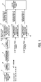
- FIG. 1 is a configuration diagram of a 128-QAM likelihood generation circuit according to a first embodiment of the present invention.
- a symbol mapping unit 12 determines coordinates on a phase plane in accordance with encoded bits output from an error correction encoding unit 11, and transmits a mapped signal.
- the signal transmitted through a transmission line channel 13 is converted to a signal of an I-axis component having a 6-bit resolution, a signal of a Q-axis component having the 6-bit resolution, and a signal being a concatenation of the I-axis component and the Q-axis component each having the 6-bit resolution.
- the signal of the I-axis component and the signal of the Q-axis component are obtained from coordinates of a reception signal point.
- the signal of the I-axis component having the 6-bit resolution is input to a one-dimensional-modulation likelihood generation LUT 15.
- the signal of the Q-axis component having the 6-bit resolution is input to a one-dimensional-modulation likelihood generation LUT 16.
- the signal being the concatenation of the I-axis component and the Q-axis component each having the 6-bit resolution is input to a two-dimensional-modulation likelihood generation LUT 17.
- the one-dimensional-modulation likelihood generation LUT 15 inputs the signal of the I-axis component as an argument to generate a likelihood of an encoded bit 0 (b0).
- the one-dimensional-modulation likelihood generation LUT 16 inputs the signal of the Q-axis component as an argument to generate a likelihood of an encoded bit 1 (b0).
- the two-dimensional-modulation likelihood generation LUT 17 inputs the signal being the concatenation of the I-axis component and the Q-axis component as an argument to generate likelihoods of an encoded bit 2 (b2) to an encoded bit 6 (b6).
- the one-dimensional-modulation likelihood generation LUT 15 corresponds to a one-dimensional-modulation lookup table to be used to generate a first likelihood.
- the one-dimensional-modulation likelihood generation LUT 16 corresponds to a one-dimensional-modulation lookup table to be used to generate a second likelihood.
- the two-dimensional-modulation likelihood generation LUT 17 corresponds to a two-dimensional-modulation lookup table to be used to generate a third likelihood.
- the three lookup tables of the one-dimensional-modulation likelihood generation LUT 15, the one-dimensional-modulation likelihood generation LUT 16, and the two-dimensional-modulation likelihood generation LUT 17 which are configured to generate the likelihoods based on the signals converted by the symbol demapping unit 14 correspond to a likelihood generation circuit.
- an error correction decoding unit 18 executes soft decision decoding based on the likelihood values generated by the likelihood generation circuit including the three lookup tables.
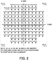
- FIG. 2 is an example of a constellation diagram for illustrating a relationship between signal points of the 128-QAM and assigned bits in the first embodiment of the present invention. As illustrated in FIG. 2 , the signal points of the 128-QAM form a non-rectangular constellation in which the signal points are not arranged as a square on the phase plane.
- FIG. 3 is a diagram for illustrating a likelihood value in accordance with the coordinates of the reception signal point for the encoded bit 0 (b0) of the 128-QAM in the first embodiment of the present invention.
- FIG. 4 is a diagram for illustrating a relationship between the I axis direction and the likelihood value of the signal point of the encoded bit 0 (b0) of the 128-QAM in the first embodiment of the present invention.
- a hatched portion of the constellation corresponds to a region in which the likelihood value is positive.
- the encoded bit 0 (b0) is assigned to only the I axis direction of the signal point, and can thus be processed by a one-dimensional modulation LUT that generates the likelihood based on only coordinate information on one axis.
- the likelihood value indicating that the encoded bit is 1 or 0 increases as the absolute value of the coordinate of the reception signal on the I axis increases.
- FIG. 5 is a diagram for illustrating a likelihood value in accordance with the coordinates of the reception signal point for the encoded bit 1 (b1) of the 128-QAM in the first embodiment of the present invention.
- FIG. 6 is a diagram for illustrating a relationship between the Q axis direction and the likelihood value of the signal point of the encoded bit 1 (b1) of the 128-QAM in the first embodiment of the present invention.
- a hatched portion of the constellation corresponds to a region in which the likelihood value is positive.
- the encoded bit 1 (b1) is assigned to only the Q axis direction of the signal point, and thus, as in a case of the encoded bit 0, can be processed by a one-dimensional modulation LUT that generates the likelihood based on only coordinate information on one axis.
- the likelihood value indicating that the encoded bit is 1 or 0 increases as the absolute value of the coordinate of the reception signal on the Q axis increases.
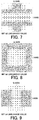
- FIG. 7 is a diagram for illustrating a likelihood value in accordance with the coordinates of the reception signal point for the encoded bit 2 (b2) of the 128-QAM in the first embodiment of the present invention.
- FIG. 8 is a diagram for illustrating a likelihood value in accordance with the coordinates of the reception signal point for the encoded bit 3 (b3) of the 128-QAM in the first embodiment of the present invention.
- FIG. 9 is a diagram for illustrating a likelihood value in accordance with the coordinates of the reception signal point for the encoded bit 4 (b4) of the 128-QAM in the first embodiment of the present invention.
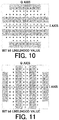
- FIG. 10 is a diagram for illustrating a likelihood value in accordance with the coordinates of the reception signal point for the encoded bit 5 (b5) of the 128-QAM in the first embodiment of the present invention.
- FIG. 11 is a diagram for illustrating a likelihood value in accordance with the coordinates of the reception signal point for the encoded bit 6 (b6) of the 128-QAM in the first embodiment of the present invention.
- a hatched portion of the constellation corresponds to a region in which the likelihood value is positive.
- Those encoded bits are assigned to signal points such that the determination cannot be made based on only the information on the I axis or the information on the Q axis. For this reason, there is required processing by a two-dimensional modulation LUT that uses the coordinate information on the I axis and the Q axis to generate the likelihoods.
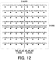
- FIG. 12 is a constellation diagram for illustrating a relationship between signal points of the 64-QAM and assigned bits in the first embodiment of the present invention. As illustrated in FIG. 12 , the signal points of the 64-QAM form a rectangular constellation in which the signal points are arranged as a square on the phase plane.
- FIG. 13 is a diagram for illustrating a likelihood value in accordance with the coordinates of the reception signal point for the encoded bit 0 (b0) of the 64-QAM in the first embodiment of the present invention.
- FIG. 14 is a diagram for illustrating a likelihood value in accordance with the coordinates of the reception signal point for the encoded bit 1 (b1) of the 64-QAM in the first embodiment of the present invention.
- FIG. 15 is a diagram for illustrating a likelihood value in accordance with the coordinates of the reception signal point for the encoded bit 2 (b2) of the 64-QAM in the first embodiment of the present invention.
- FIG. 16 is a diagram for illustrating a likelihood value in accordance with the coordinates of the reception signal point for the encoded bit 3 (b3) of the 64-QAM in the first embodiment of the present invention.
- FIG. 17 is a diagram for illustrating a likelihood value in accordance with the coordinates of the reception signal point for the encoded bit 4 (b4) of the 64-QAM in the first embodiment of the present invention.
- FIG. 18 is a diagram for illustrating a likelihood value in accordance with the coordinates of the reception signal point for the encoded bit 5 (b5) of the 64-QAM in the first embodiment of the present invention.
- the encoded bits b0 to b2 are assigned to only the I axis direction of the signal point, and can thus be processed by a one-dimensional modulation LUT that generates the likelihoods based on only coordinate information on one axis.
- the encoded bits b3 to b5 are assigned to only the Q axis direction of the signal point, and can thus be processed by a one-dimensional modulation LUT that generates the likelihoods based on only coordinate information on one axis, as in the case of the encoded bits b0 to b2.
- FIG. 19 is a configuration diagram of a 64-QAM likelihood generation LUT in the first embodiment of the present invention.
- An I axis component having a 6-bit resolution obtained from the coordinates of the reception signal point is input to a one-dimensional-modulation likelihood generation LUT 121.
- a Q-axis component having the 6-bit resolution is input to a one-dimensional-modulation likelihood generation LUT 122.
- the one-dimensional-modulation likelihood generation LUT 121 generates likelihoods of the encoded bit 0 (b0), the encoded bit 1 (b1), and the encoded bit 2 (b2) based on the I-axis component having the 6-bit resolution. Meanwhile, the one-dimensional-modulation likelihood generation LUT 122 generates likelihoods of the encoded bit 3 (b3), the encoded bit 4 (b4), and the encoded bit 5 (b5) based on the Q-axis component having the 6-bit resolution.
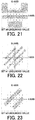
- FIG. 20 is a constellation diagram for illustrating a relationship between signal points of the 32-QAM and assigned bits in the first embodiment of the present invention. As illustrated in FIG. 20 , the signal points of the 32-QAM form a non-rectangular constellation in which the signal points are not arranged as a square on the phase plane.
- FIG. 21 is a diagram for illustrating a likelihood value in accordance with the coordinates of the reception signal point for the encoded bit 0 (b0) of the 32-QAM in the first embodiment of the present invention.
- FIG. 22 is a diagram for illustrating a likelihood value in accordance with the coordinates of the reception signal point for the encoded bit b1 (b1) of the 32-QAM in the first embodiment of the present invention.
- FIG. 23 is a diagram for illustrating a likelihood value in accordance with the coordinates of the reception signal point for the encoded bit b2 (b2) of the 32-QAM in the first embodiment of the present invention.
- FIG. 24 is a diagram for illustrating a likelihood value in accordance with the coordinates of the reception signal point for the encoded bit b3 (b3) of the 32-QAM in the first embodiment of the present invention.
- FIG. 25 is a diagram for illustrating a likelihood value in accordance with the coordinates of the reception signal point for the encoded bit b4 (b4) of the 32-QAM in the first embodiment of the present invention.
- Hatched portions of FIG. 21 to FIG. 25 each indicate a region in which the likelihood value is positive.
- the signal points exist such that the determination cannot be made based on only the information on the I axis or the information on the Q axis. For this reason, there is required processing by a two-dimensional modulation LUT that uses the coordinate information on the I axis and the Q axis to generate the likelihoods.
- FIG. 26 is a configuration diagram of a 32-QAM likelihood generation LUT in the first embodiment of the present invention.
- a signal being a concatenation of an I-axis component and a Q-axis component, each of which has a 6-bit resolution, and is obtained from coordinates of the reception signal point, is input to a two-dimensional-modulation likelihood generation LUT 151.
- the two-dimensional-modulation likelihood generation LUT 151 generates likelihoods of the encoded bit 0 (b0), the encoded bit 1 (b1), the encoded bit 2 (b2), the encoded bit 3 (b3), and the encoded bit 4 (b4) based on the signal being the concatenation of the I-axis component and the Q-axis component each having the 6-bit resolution.
- the 32-QAM likelihood generation LUT and the 64-QAM likelihood generation LUTs have the same configurations as those of the one-dimensional-modulation likelihood generation LUT forming the 128-QAM likelihood generation circuit and the two-dimensional-modulation likelihood generation LUTs forming the 128-QAM likelihood generation circuit, respectively. Consequently, the 32-QAM likelihood generation circuit and the 64-QAM likelihood generation circuit can be shared so as to be used as the 128-QAM likelihood generation circuit.
- a high-order non-rectangular QAM is formed of one-dimensional-modulation likelihood generation circuits and a two-dimensional-modulation likelihood generation circuit.
- likelihood generation circuits used for a low-order non-rectangular QAM and a low-order rectangular QAM can be shared to be used as a likelihood generation circuit used for a high-order non-rectangular QAM.
- a likelihood generation circuit capable of suppressing an increase in circuit scale for the likelihood generation through use of LUTs.
- Such a likelihood generation circuit can be applied to an optical transmission device that employs a non-rectangular high-order modulation method equal to or higher than 8-QAM.
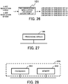
- FIG. 27 is a configuration diagram for illustrating a case in which each function of the optical transmission device according to the first embodiment of the present invention is implemented by a processing circuit 1000 being dedicated hardware.
- FIG. 28 is a configuration diagram for illustrating a case in which each function of the optical transmission device according to the first embodiment of the present invention is implemented by a processing circuit 2000 that includes a processor 2001 and a memory 2002.
- the processing circuit 1000 corresponds to, for example, a single circuit, a composite circuit, a programmed processor, a parallel-programmed processor, an application specific integrated circuit (ASIC), a field programmable gate array (FPGA), or a combination thereof.
- ASIC application specific integrated circuit
- FPGA field programmable gate array
- the functions of the respective units of the symbol demapping unit, the likelihood generation circuit, and the error correction decoding unit forming the optical transmission device may be implemented by individual processing circuits 1000, or may altogether by implemented by the processing circuit 1000.
- the processing circuit is the processor 2001
- the functions of the respective units of the symbol demapping unit, the likelihood generation circuit, and the error correction decoding unit are implemented by software, firmware, or a combination of software and firmware.
- the software and the firmware are coded as a program and stored in the memory 2002.
- the processor 2001 reads out and executes the program stored in the memory 2002, to thereby implement the function of each of the units. That is, the optical transmission device includes the memory 2002 configured to store programs the execution of which by the processing circuit 2000 ultimately leads to the implementation of each processing step.
- the memory 2002 corresponds to, for example, a random access memory (RAM), a read only memory (ROM), a flash memory, an erasable programmable read only memory (EPROM), an electrically erasable and programmable read only memory (EEPROM), or other such non-volatile or volatile semiconductor memory.
- RAM random access memory
- ROM read only memory
- EPROM erasable programmable read only memory
- EEPROM electrically erasable and programmable read only memory
- the memory 2002 also corresponds to, for example, a magnetic disk, a flexible disk, an optical disc, a compact disc, a MiniDisk, or a DVD.
- the processing circuit can implement the function of each of the units described above by hardware, software, firmware, or a combination thereof.
- 11 error correction encoding unit 12 symbol mapping unit, 13 transmission line channel, 14 symbol demapping unit, 15 one-dimensional-modulation likelihood generation LUT for I-axis component, 16 one-dimensional-modulation likelihood generation LUT for Q-axis component, 17 two-dimensional-modulation likelihood generation LUT, 18 error correction decoding unit, 121 one-dimensional-modulation likelihood generation LUT for I-axis component, 122 one-dimensional-modulation likelihood generation LUT for Q-axis component, 151 two-dimensional-modulation likelihood generation LUT
Landscapes
- Engineering & Computer Science (AREA)
- Computer Networks & Wireless Communication (AREA)
- Signal Processing (AREA)
- Physics & Mathematics (AREA)
- Electromagnetism (AREA)
- Probability & Statistics with Applications (AREA)
- Theoretical Computer Science (AREA)
- Power Engineering (AREA)
- Error Detection And Correction (AREA)
- Optical Communication System (AREA)
- Digital Transmission Methods That Use Modulated Carrier Waves (AREA)
Abstract
Description
- The present invention relates to an optical transmission device configured to execute soft decision decoding, and a likelihood generation circuit to be used for an optical transmission device.
- In recent years, in modulation methods applied to optical transmission systems, an increase in order of modulation has been in progress as a bit rate of transmission data increases. Further, as a result of achievement of large-scale digital circuits due to miniaturization in a semiconductor manufacturing process and appearance of ultra-high-speed analog digital converters (ADCs) and digital analog converters (DACs) having a sampling speed of some tens of giga samples per second (Gsps), complicated optical signals can be generated and demodulated.
- Consequently, there have been developed high-order modulation methods having extremely high orders which was not achieved by related-art optical communication, such as 64-quadrature amplitude modulation (QAM), 128-QAM, and 256-QAM.
- In those high-order modulation methods, arrangement intervals between signal points are narrow on a phase plane, and a high signal noise ratio (SNR) is thus required in order to achieve a required transmission distance and a required signal speed. In order to compensate for a deficiency of the SNR, there has further been increasing importance of efficient error correction codes capable of providing a high speed and a high coding gain, for example, low density parity check (LDPC). Thus, the LDPC is used in combination with another error correction code.
- For the error correction codes, hard decision decoding and soft decision decoding are executed. The hard decision decoding decides 1 or 0 through use of only a received information sequence. Meanwhile, as a method of enhancing performance, the soft decision decoding uses also analog information on the signal. In the soft decision decoding, the error correction is executed by calculating a likelihood indicating a probability of bits assigned to a signal point from coordinates of the reception signal on the phase plane.
- In the calculation of the likelihood in the soft decision decoding, arithmetic calculation processing imposing high load is required to be performed on quantized multi-bit information, and a circuit scale increases accordingly in implementation. To cope with this problem, in place of this high-load arithmetic calculation processing, there are used methods for reducing the circuit scale through use of, for example, approximation of a calculation equation to be used for the likelihood calculation and a lookup table (LUT) that stores likelihoods calculated in advance and inputs the coordinates to output a value (for example, see Patent Literature 1).
- In the method described in
Patent Literature 1, bits that are on the in-phase (I) axis and the quadrature-phase (Q) axis of the phase plane and are obtained from a reception signal point through use of the hard decision decoding are used to detect a quadrature of the phase plane in which the coordinates of the reception signal point exist. After that, in the method described inPatent Literature 1, based on the information on the quadrature, likelihood information obtained as primary information is converted to final likelihood information. As described above, inPatent Literature 1, there is described the method of limiting a scope within which the value of the likelihood varies depending on the position of the reception signal point to only a range between adjacent signal points including a hard-decision threshold value to reduce the scale of the likelihood generation circuit, thereby downsizing the likelihood generation circuit. - [PTL 1]
WO 2008/038749 A1 - However, the related art has the following problem.
- Due to the advent of a digital coherent technology, an increase in capacity exceeding 1 Tbps of a transmission capacity per one channel unit is in progress in the optical communication system. As a result, the circuit scale of a digital circuit for executing signal processing is approaching a limit of integration of large scale integration (LSI) circuits.
- Moreover, meanwhile, as the scope of application of the optical communication system extends to a data center and the like, it is required to use the same LSI to transmit and receive signals modulated by various methods ranging from the quadrature phase shift keying (QPSK) to the 128-QAM.
- An LUT to be used to execute the likelihood generation is implemented as a circuit in which the coordinates of the reception signal are used as an input address of a random access memory (RAM) and a likelihood corresponding to the coordinates is stored as data of the RAM to be output. Even in the circuit reduction method of the type using the LUT, when LUTs are individually prepared for various modulation methods, there occurs such a problem that the circuit scale becomes enormous particularly for an extremely high-order modulation method.
- The present invention has been made to solve the above-mentioned problem, and has an object to provide an optical transmission device and a likelihood generation circuit which are capable of suppressing an increase in circuit scale at a time when LUTs are used to generate a likelihood.
- According to one embodiment of the present invention, there is provided an optical transmission device including: a symbol demapping unit configured to convert a reception signal to a signal of an I-axis component and a signal of a Q-axis component on a phase plane, and a signal being a concatenation of the signal of the I-axis component and the signal of the Q-axis component; a likelihood generation circuit configured to generate likelihoods relating to the reception signal based on the signal of the I-axis component and the signal of the Q-axis component converted by the symbol demapping unit and on the signal being the concatenation of the signal of the I-axis component and the signal of the Q-axis component; and an error correction decoding unit configured to execute soft decision decoding on the reception signal based on the likelihoods generated by the likelihood generation circuit, wherein the likelihood generation circuit includes: a first one-dimensional-modulation lookup table configured to input the signal of the I-axis component as an argument to output a first likelihood; a second one-dimensional-modulation lookup table configured to input the signal of the Q-axis component as an argument to output a second likelihood; and a two-dimensional-modulation lookup table configured to input, as an argument, the signal being the concatenation of the signal of the I-axis component and the signal of the Q-axis component, to generate a third likelihood, and wherein the error correction decoding unit is configured to execute the soft decision decoding based on the first likelihood, the second likelihood, and the third likelihood.
- According to one embodiment of the present invention, there is provided a likelihood generation circuit including: a first one-dimensional-modulation lookup table configured to input, as an argument, a signal of an I-axis component out of signals obtained by converting a reception signal to the signals on a phase plane, to output a first likelihood; a second one-dimensional-modulation lookup table configured to input, as an argument, a signal of a q-axis component out of the signals obtained by converting the reception signal to the signals on the phase plane, to output a second likelihood; and a two-dimensional-modulation lookup table configured to input, as an argument, a signal being a concatenation of the signal of the I-axis component and the signal of the Q-axis component, to generate a third likelihood, the signal of the I-axis component and the signal of the Q-axis component being the signals obtained by converting the reception signal to the signals on the phase plane.
- According to the present invention, it is possible to provide the optical transmission device and the likelihood generation circuit which are capable of suppressing an increase in circuit scale at the time when LUTs are used to generate the likelihood.
-
-
FIG. 1 is a configuration diagram of a 128-QAM likelihood generation circuit according to a first embodiment of the present invention. -
FIG. 2 is an example of a constellation diagram for illustrating a relationship between signal points of 128-QAM and assigned bits in the first embodiment of the present invention. -
FIG. 3 is a diagram for illustrating a likelihood value in accordance with coordinates of a reception signal point for an encoded bit 0 (b0) of the 128-QAM in the first embodiment of the present invention. -
FIG. 4 is a diagram for illustrating a relationship between an I axis direction and the likelihood value of the signal point of the encoded bit 0 (b0) of the 128-QAM in the first embodiment of the present invention. -
FIG. 5 is a diagram for illustrating a likelihood value in accordance with the coordinates of the reception signal point for an encoded bit 1 (b1) of the 128-QAM in the first embodiment of the present invention. -
FIG. 6 is a diagram for illustrating a relationship between a Q axis direction and the likelihood of the signal point for the encoded bit 1 (b1) of the 128-QAM in the first embodiment of the present invention. -
FIG. 7 is a diagram for illustrating a likelihood value in accordance with the coordinates of the reception signal point for an encoded bit 2 (b2) of the 128-QAM in the first embodiment of the present invention. -
FIG. 8 is a diagram for illustrating a likelihood value in accordance with the coordinates of the reception signal point for an encoded bit 3 (b3) of the 128-QAM in the first embodiment of the present invention. -
FIG. 9 is a diagram for illustrating a likelihood value in accordance with the coordinates of the reception signal point for an encoded bit 4 (b4) of the 128-QAM in the first embodiment of the present invention. -
FIG. 10 is a diagram for illustrating a likelihood value in accordance with the coordinates of the reception signal point for an encoded bit 5 (b5) of the 128-QAM in the first embodiment of the present invention. -
FIG. 11 is a diagram for illustrating a likelihood value in accordance with the coordinates of the reception signal point for an encoded bit 6 (b6) of the 128-QAM in the first embodiment of the present invention. -
FIG. 12 is a constellation diagram for illustrating a relationship between signal points of 64-QAM and assigned bits in the first embodiment of the present invention. -
FIG. 13 is a diagram for illustrating a likelihood value in accordance with the coordinates of the reception signal point for an encoded bit b0 (b0) of the 64-QAM in the first embodiment of the present invention. -
FIG. 14 is a diagram for illustrating a likelihood value in accordance with the coordinates of the reception signal point for an encoded bit b1 (b1) of the 64-QAM in the first embodiment of the present invention. -
FIG. 15 is a diagram for illustrating a likelihood value in accordance with the coordinates of the reception signal point for an encoded bit b2 (b2) of the 64-QAM in the first embodiment of the present invention. -
FIG. 16 is a diagram for illustrating a likelihood value in accordance with the coordinates of the reception signal point for an encoded bit b3 (b3) of the 64-QAM in the first embodiment of the present invention. -
FIG. 17 is a diagram for illustrating a likelihood value in accordance with the coordinates of the reception signal point for an encoded bit b4 (b4) of the 64-QAM in the first embodiment of the present invention. -
FIG. 18 is a diagram for illustrating a likelihood value in accordance with the coordinates of the reception signal point for an encoded bit b5 (b5) of the 64-QAM in the first embodiment of the present invention. -
FIG. 19 is a configuration diagram of a 64-QAM likelihood generation LUT in the first embodiment of the present invention. -
FIG. 20 is a constellation diagram for illustrating a relationship between signal points of 32-QAM and assigned bits in the first embodiment of the present invention. -
FIG. 21 is a diagram for illustrating a likelihood value in accordance with the coordinates of the reception signal point for an encoded bit b0 (b0) of the 32-QAM in the first embodiment of the present invention. -
FIG. 22 is a diagram for illustrating a likelihood value in accordance with the coordinates of the reception signal point for an encoded bit b1 (b1) of the 32-QAM in the first embodiment of the present invention. -
FIG. 23 is a diagram for illustrating a likelihood value in accordance with the coordinates of the reception signal point for an encoded bit b2 (b2) of the 32-QAM in the first embodiment of the present invention. -
FIG. 24 is a diagram for illustrating a likelihood value in accordance with the coordinates of the reception signal point for an encoded bit b3 (b3) of the 32-QAM in the first embodiment of the present invention. -
FIG. 25 is a diagram for illustrating a likelihood value in accordance with the coordinates of the reception signal point for an encoded bit b4 (b4) of the 32-QAM in the first embodiment of the present invention. -
FIG. 26 is a configuration diagram of a 32-QAM likelihood generation LUT in the first embodiment of the present invention. -
FIG. 27 is a configuration diagram for illustrating a case in which each function of an optical transmission device according to the first embodiment of the present invention is implemented by a processing circuit being dedicated hardware. -
FIG. 28 is a configuration diagram for illustrating a case in which each function of the optical transmission device according to the first embodiment of the present invention is implemented by a processing circuit that includes a processor and a memory. - Now, with reference to the drawings, an optical transmission device and a likelihood generation circuit according to a preferred embodiment of the present invention are described.
-
FIG. 1 is a configuration diagram of a 128-QAM likelihood generation circuit according to a first embodiment of the present invention. Asymbol mapping unit 12 determines coordinates on a phase plane in accordance with encoded bits output from an errorcorrection encoding unit 11, and transmits a mapped signal. - In a
symbol demapping unit 14, the signal transmitted through atransmission line channel 13 is converted to a signal of an I-axis component having a 6-bit resolution, a signal of a Q-axis component having the 6-bit resolution, and a signal being a concatenation of the I-axis component and the Q-axis component each having the 6-bit resolution. The signal of the I-axis component and the signal of the Q-axis component are obtained from coordinates of a reception signal point. - After that, the signal of the I-axis component having the 6-bit resolution is input to a one-dimensional-modulation
likelihood generation LUT 15. Moreover, the signal of the Q-axis component having the 6-bit resolution is input to a one-dimensional-modulationlikelihood generation LUT 16. Further, the signal being the concatenation of the I-axis component and the Q-axis component each having the 6-bit resolution is input to a two-dimensional-modulationlikelihood generation LUT 17. - The one-dimensional-modulation
likelihood generation LUT 15 inputs the signal of the I-axis component as an argument to generate a likelihood of an encoded bit 0 (b0). The one-dimensional-modulationlikelihood generation LUT 16 inputs the signal of the Q-axis component as an argument to generate a likelihood of an encoded bit 1 (b0). Further, the two-dimensional-modulationlikelihood generation LUT 17 inputs the signal being the concatenation of the I-axis component and the Q-axis component as an argument to generate likelihoods of an encoded bit 2 (b2) to an encoded bit 6 (b6). - That is, the one-dimensional-modulation
likelihood generation LUT 15 corresponds to a one-dimensional-modulation lookup table to be used to generate a first likelihood. Further, the one-dimensional-modulationlikelihood generation LUT 16 corresponds to a one-dimensional-modulation lookup table to be used to generate a second likelihood. Further, the two-dimensional-modulationlikelihood generation LUT 17 corresponds to a two-dimensional-modulation lookup table to be used to generate a third likelihood. - Moreover, the three lookup tables of the one-dimensional-modulation
likelihood generation LUT 15, the one-dimensional-modulationlikelihood generation LUT 16, and the two-dimensional-modulationlikelihood generation LUT 17 which are configured to generate the likelihoods based on the signals converted by thesymbol demapping unit 14 correspond to a likelihood generation circuit. - After that, an error
correction decoding unit 18 executes soft decision decoding based on the likelihood values generated by the likelihood generation circuit including the three lookup tables. -
FIG. 2 is an example of a constellation diagram for illustrating a relationship between signal points of the 128-QAM and assigned bits in the first embodiment of the present invention. As illustrated inFIG. 2 , the signal points of the 128-QAM form a non-rectangular constellation in which the signal points are not arranged as a square on the phase plane. -
FIG. 3 is a diagram for illustrating a likelihood value in accordance with the coordinates of the reception signal point for the encoded bit 0 (b0) of the 128-QAM in the first embodiment of the present invention.FIG. 4 is a diagram for illustrating a relationship between the I axis direction and the likelihood value of the signal point of the encoded bit 0 (b0) of the 128-QAM in the first embodiment of the present invention. A hatched portion of the constellation corresponds to a region in which the likelihood value is positive. The encoded bit 0 (b0) is assigned to only the I axis direction of the signal point, and can thus be processed by a one-dimensional modulation LUT that generates the likelihood based on only coordinate information on one axis. The likelihood value indicating that the encoded bit is 1 or 0 increases as the absolute value of the coordinate of the reception signal on the I axis increases. -
FIG. 5 is a diagram for illustrating a likelihood value in accordance with the coordinates of the reception signal point for the encoded bit 1 (b1) of the 128-QAM in the first embodiment of the present invention.FIG. 6 is a diagram for illustrating a relationship between the Q axis direction and the likelihood value of the signal point of the encoded bit 1 (b1) of the 128-QAM in the first embodiment of the present invention. A hatched portion of the constellation corresponds to a region in which the likelihood value is positive. - The encoded bit 1 (b1) is assigned to only the Q axis direction of the signal point, and thus, as in a case of the encoded
bit 0, can be processed by a one-dimensional modulation LUT that generates the likelihood based on only coordinate information on one axis. The likelihood value indicating that the encoded bit is 1 or 0 increases as the absolute value of the coordinate of the reception signal on the Q axis increases. -
FIG. 7 is a diagram for illustrating a likelihood value in accordance with the coordinates of the reception signal point for the encoded bit 2 (b2) of the 128-QAM in the first embodiment of the present invention.FIG. 8 is a diagram for illustrating a likelihood value in accordance with the coordinates of the reception signal point for the encoded bit 3 (b3) of the 128-QAM in the first embodiment of the present invention.FIG. 9 is a diagram for illustrating a likelihood value in accordance with the coordinates of the reception signal point for the encoded bit 4 (b4) of the 128-QAM in the first embodiment of the present invention. -
FIG. 10 is a diagram for illustrating a likelihood value in accordance with the coordinates of the reception signal point for the encoded bit 5 (b5) of the 128-QAM in the first embodiment of the present invention. Further,FIG. 11 is a diagram for illustrating a likelihood value in accordance with the coordinates of the reception signal point for the encoded bit 6 (b6) of the 128-QAM in the first embodiment of the present invention. - A hatched portion of the constellation corresponds to a region in which the likelihood value is positive. Those encoded bits are assigned to signal points such that the determination cannot be made based on only the information on the I axis or the information on the Q axis. For this reason, there is required processing by a two-dimensional modulation LUT that uses the coordinate information on the I axis and the Q axis to generate the likelihoods.
-
FIG. 12 is a constellation diagram for illustrating a relationship between signal points of the 64-QAM and assigned bits in the first embodiment of the present invention. As illustrated inFIG. 12 , the signal points of the 64-QAM form a rectangular constellation in which the signal points are arranged as a square on the phase plane. -
FIG. 13 is a diagram for illustrating a likelihood value in accordance with the coordinates of the reception signal point for the encoded bit 0 (b0) of the 64-QAM in the first embodiment of the present invention.FIG. 14 is a diagram for illustrating a likelihood value in accordance with the coordinates of the reception signal point for the encoded bit 1 (b1) of the 64-QAM in the first embodiment of the present invention.FIG. 15 is a diagram for illustrating a likelihood value in accordance with the coordinates of the reception signal point for the encoded bit 2 (b2) of the 64-QAM in the first embodiment of the present invention. -
FIG. 16 is a diagram for illustrating a likelihood value in accordance with the coordinates of the reception signal point for the encoded bit 3 (b3) of the 64-QAM in the first embodiment of the present invention.FIG. 17 is a diagram for illustrating a likelihood value in accordance with the coordinates of the reception signal point for the encoded bit 4 (b4) of the 64-QAM in the first embodiment of the present invention. Further,FIG. 18 is a diagram for illustrating a likelihood value in accordance with the coordinates of the reception signal point for the encoded bit 5 (b5) of the 64-QAM in the first embodiment of the present invention. - The encoded bits b0 to b2 are assigned to only the I axis direction of the signal point, and can thus be processed by a one-dimensional modulation LUT that generates the likelihoods based on only coordinate information on one axis. Meanwhile, the encoded bits b3 to b5 are assigned to only the Q axis direction of the signal point, and can thus be processed by a one-dimensional modulation LUT that generates the likelihoods based on only coordinate information on one axis, as in the case of the encoded bits b0 to b2.
-
FIG. 19 is a configuration diagram of a 64-QAM likelihood generation LUT in the first embodiment of the present invention. An I axis component having a 6-bit resolution obtained from the coordinates of the reception signal point is input to a one-dimensional-modulationlikelihood generation LUT 121. Meanwhile, a Q-axis component having the 6-bit resolution is input to a one-dimensional-modulationlikelihood generation LUT 122. - After that, the one-dimensional-modulation
likelihood generation LUT 121 generates likelihoods of the encoded bit 0 (b0), the encoded bit 1 (b1), and the encoded bit 2 (b2) based on the I-axis component having the 6-bit resolution. Meanwhile, the one-dimensional-modulationlikelihood generation LUT 122 generates likelihoods of the encoded bit 3 (b3), the encoded bit 4 (b4), and the encoded bit 5 (b5) based on the Q-axis component having the 6-bit resolution. -
FIG. 20 is a constellation diagram for illustrating a relationship between signal points of the 32-QAM and assigned bits in the first embodiment of the present invention. As illustrated inFIG. 20 , the signal points of the 32-QAM form a non-rectangular constellation in which the signal points are not arranged as a square on the phase plane. -
FIG. 21 is a diagram for illustrating a likelihood value in accordance with the coordinates of the reception signal point for the encoded bit 0 (b0) of the 32-QAM in the first embodiment of the present invention.FIG. 22 is a diagram for illustrating a likelihood value in accordance with the coordinates of the reception signal point for the encoded bit b1 (b1) of the 32-QAM in the first embodiment of the present invention.FIG. 23 is a diagram for illustrating a likelihood value in accordance with the coordinates of the reception signal point for the encoded bit b2 (b2) of the 32-QAM in the first embodiment of the present invention. -
FIG. 24 is a diagram for illustrating a likelihood value in accordance with the coordinates of the reception signal point for the encoded bit b3 (b3) of the 32-QAM in the first embodiment of the present invention. Further,FIG. 25 is a diagram for illustrating a likelihood value in accordance with the coordinates of the reception signal point for the encoded bit b4 (b4) of the 32-QAM in the first embodiment of the present invention. - Hatched portions of
FIG. 21 to FIG. 25 each indicate a region in which the likelihood value is positive. As illustrated inFIG. 21 to FIG. 25 , the signal points exist such that the determination cannot be made based on only the information on the I axis or the information on the Q axis. For this reason, there is required processing by a two-dimensional modulation LUT that uses the coordinate information on the I axis and the Q axis to generate the likelihoods. -
FIG. 26 is a configuration diagram of a 32-QAM likelihood generation LUT in the first embodiment of the present invention. A signal being a concatenation of an I-axis component and a Q-axis component, each of which has a 6-bit resolution, and is obtained from coordinates of the reception signal point, is input to a two-dimensional-modulationlikelihood generation LUT 151. After that, the two-dimensional-modulationlikelihood generation LUT 151 generates likelihoods of the encoded bit 0 (b0), the encoded bit 1 (b1), the encoded bit 2 (b2), the encoded bit 3 (b3), and the encoded bit 4 (b4) based on the signal being the concatenation of the I-axis component and the Q-axis component each having the 6-bit resolution. - The 32-QAM likelihood generation LUT and the 64-QAM likelihood generation LUTs have the same configurations as those of the one-dimensional-modulation likelihood generation LUT forming the 128-QAM likelihood generation circuit and the two-dimensional-modulation likelihood generation LUTs forming the 128-QAM likelihood generation circuit, respectively. Consequently, the 32-QAM likelihood generation circuit and the 64-QAM likelihood generation circuit can be shared so as to be used as the 128-QAM likelihood generation circuit.
- In other words, in the first embodiment, a high-order non-rectangular QAM is formed of one-dimensional-modulation likelihood generation circuits and a two-dimensional-modulation likelihood generation circuit. With this configuration, likelihood generation circuits used for a low-order non-rectangular QAM and a low-order rectangular QAM can be shared to be used as a likelihood generation circuit used for a high-order non-rectangular QAM. As a result, there is achieved a likelihood generation circuit capable of suppressing an increase in circuit scale for the likelihood generation through use of LUTs. Such a likelihood generation circuit can be applied to an optical transmission device that employs a non-rectangular high-order modulation method equal to or higher than 8-QAM.
- Each function of the optical transmission device according to the first embodiment described above is implemented by a processing circuit. The processing circuit for implementing each function may be dedicated hardware, or a processor configured to execute a program stored in a memory.
FIG. 27 is a configuration diagram for illustrating a case in which each function of the optical transmission device according to the first embodiment of the present invention is implemented by aprocessing circuit 1000 being dedicated hardware. Moreover,FIG. 28 is a configuration diagram for illustrating a case in which each function of the optical transmission device according to the first embodiment of the present invention is implemented by aprocessing circuit 2000 that includes aprocessor 2001 and amemory 2002. - When the processing circuit is dedicated hardware, the
processing circuit 1000 corresponds to, for example, a single circuit, a composite circuit, a programmed processor, a parallel-programmed processor, an application specific integrated circuit (ASIC), a field programmable gate array (FPGA), or a combination thereof. The functions of the respective units of the symbol demapping unit, the likelihood generation circuit, and the error correction decoding unit forming the optical transmission device may be implemented byindividual processing circuits 1000, or may altogether by implemented by theprocessing circuit 1000. - Meanwhile, when the processing circuit is the
processor 2001, the functions of the respective units of the symbol demapping unit, the likelihood generation circuit, and the error correction decoding unit are implemented by software, firmware, or a combination of software and firmware. The software and the firmware are coded as a program and stored in thememory 2002. - The
processor 2001 reads out and executes the program stored in thememory 2002, to thereby implement the function of each of the units. That is, the optical transmission device includes thememory 2002 configured to store programs the execution of which by theprocessing circuit 2000 ultimately leads to the implementation of each processing step. - It is also understood that those programs cause a computer to execute the steps and methods described above for the respective units. In this case, the
memory 2002 corresponds to, for example, a random access memory (RAM), a read only memory (ROM), a flash memory, an erasable programmable read only memory (EPROM), an electrically erasable and programmable read only memory (EEPROM), or other such non-volatile or volatile semiconductor memory. Thememory 2002 also corresponds to, for example, a magnetic disk, a flexible disk, an optical disc, a compact disc, a MiniDisk, or a DVD. - Some of the functions of the respective units described above may be implemented by dedicated hardware, and others thereof may be implemented by software or firmware.
- In this manner, the processing circuit can implement the function of each of the units described above by hardware, software, firmware, or a combination thereof.
- 11 error correction encoding unit, 12 symbol mapping unit, 13 transmission line channel, 14 symbol demapping unit, 15 one-dimensional-modulation likelihood generation LUT for I-axis component, 16 one-dimensional-modulation likelihood generation LUT for Q-axis component, 17 two-dimensional-modulation likelihood generation LUT, 18 error correction decoding unit, 121 one-dimensional-modulation likelihood generation LUT for I-axis component, 122 one-dimensional-modulation likelihood generation LUT for Q-axis component, 151 two-dimensional-modulation likelihood generation LUT
Claims (2)
- An optical transmission device, comprising:a symbol demapping unit configured to convert a reception signal to a signal of an I-axis component and a signal of a Q-axis component on a phase plane, and a signal being a concatenation of the signal of the I-axis component and the signal of the Q-axis component;a likelihood generation circuit configured to generate likelihoods relating to the reception signal based on the signal of the I-axis component and the signal of the Q-axis component converted by the symbol demapping unit and on the signal being the concatenation of the signal of the I-axis component and the signal of the Q-axis component; andan error correction decoding unit configured to execute soft decision decoding on the reception signal based on the likelihoods generated by the likelihood generation circuit,wherein the likelihood generation circuit includes:a first one-dimensional-modulation lookup table configured to input the signal of the I-axis component as an argument to output a first likelihood;a second one-dimensional-modulation lookup table configured to input the signal of the Q-axis component as an argument to output a second likelihood; anda two-dimensional-modulation lookup table configured to input, as an argument, the signal being the concatenation of the signal of the I-axis component and the signal of the Q-axis component, to generate a third likelihood, andwherein the error correction decoding unit is configured to execute the soft decision decoding based on the first likelihood, the second likelihood, and the third likelihood.
- A likelihood generation circuit, comprising:a first one-dimensional-modulation lookup table configured to input, as an argument, a signal of an I-axis component out of signals obtained by converting a reception signal to the signals on a phase plane, to output a first likelihood;a second one-dimensional-modulation lookup table configured to input, as an argument, a signal of a q-axis component out of the signals obtained by converting the reception signal to the signals on the phase plane, to output a second likelihood; anda two-dimensional-modulation lookup table configured to input, as an argument, a signal being a concatenation of the signal of the I-axis component and the signal of the Q-axis component, to generate a third likelihood, the signal of the I-axis component and the signal of the Q-axis component being the signals obtained by converting the reception signal to the signals on the phase plane.
Applications Claiming Priority (1)
| Application Number | Priority Date | Filing Date | Title |
|---|---|---|---|
| PCT/JP2019/009621 WO2020183555A1 (en) | 2019-03-11 | 2019-03-11 | Optical transmission device and likelihood generation circuit |
Publications (3)
| Publication Number | Publication Date |
|---|---|
| EP3926836A1 true EP3926836A1 (en) | 2021-12-22 |
| EP3926836A4 EP3926836A4 (en) | 2022-03-02 |
| EP3926836B1 EP3926836B1 (en) | 2023-01-18 |
Family
ID=69166795
Family Applications (1)
| Application Number | Title | Priority Date | Filing Date |
|---|---|---|---|
| EP19919078.6A Active EP3926836B1 (en) | 2019-03-11 | 2019-03-11 | Optical transmission device and likelihood generation circuit |
Country Status (5)
| Country | Link |
|---|---|
| US (1) | US11736127B2 (en) |
| EP (1) | EP3926836B1 (en) |
| JP (1) | JP6633262B1 (en) |
| CN (1) | CN113519126B (en) |
| WO (1) | WO2020183555A1 (en) |
Family Cites Families (12)
| Publication number | Priority date | Publication date | Assignee | Title |
|---|---|---|---|---|
| JPH1117755A (en) * | 1997-06-25 | 1999-01-22 | Futaba Corp | Phase discrimination circuit |
| KR100660056B1 (en) * | 2005-11-07 | 2006-12-20 | 한국전자통신연구원 | Device for independent stream extraction and soft decision of hierarchical modulated signals and method thereof |
| US8675771B2 (en) | 2006-09-29 | 2014-03-18 | Nec Corporation | Log likelihood ratio arithmetic circuit, transmission apparatus, log likelihood ratio arithmetic method, and program |
| KR20090003636A (en) * | 2007-07-03 | 2009-01-12 | 삼성전자주식회사 | Apparatus and method for symbol demapping in wireless communication system and receiver for same |
| KR20120132994A (en) * | 2011-05-30 | 2012-12-10 | 삼성전자주식회사 | Apparatus and method for soft demmaping |
| JP6075446B2 (en) * | 2013-04-23 | 2017-02-08 | 日本電気株式会社 | Demodulator, demodulation method and program |
| JP5955481B2 (en) * | 2014-02-24 | 2016-07-20 | 三菱電機株式会社 | Soft decision value generation apparatus and soft decision value generation method |
| EP3119051B1 (en) * | 2014-03-13 | 2019-11-20 | Mitsubishi Electric Corporation | Likelihood generation device and method therefor |
| JPWO2017158725A1 (en) * | 2016-03-15 | 2019-01-17 | 三菱電機株式会社 | Log likelihood ratio calculation circuit, receiving apparatus, and log likelihood ratio calculation method |
| US10742354B2 (en) * | 2016-06-21 | 2020-08-11 | Nippon Telegraph And Telephone Corporation | Optical receiver, optical transmission device, and method for optical receiver |
| CN106059985A (en) * | 2016-07-29 | 2016-10-26 | 武汉芯泰科技有限公司 | Demodulating device and demodulating method based on vector |
| CN109644010B (en) * | 2016-09-01 | 2022-12-20 | 三菱电机株式会社 | Likelihood generating device, receiving device, likelihood generating method, and optical transmission system |
-
2019
- 2019-03-11 CN CN201980093476.5A patent/CN113519126B/en active Active
- 2019-03-11 JP JP2019541813A patent/JP6633262B1/en active Active
- 2019-03-11 WO PCT/JP2019/009621 patent/WO2020183555A1/en not_active Ceased
- 2019-03-11 EP EP19919078.6A patent/EP3926836B1/en active Active
-
2021
- 2021-08-18 US US17/405,461 patent/US11736127B2/en active Active
Also Published As
| Publication number | Publication date |
|---|---|
| JPWO2020183555A1 (en) | 2021-03-18 |
| EP3926836B1 (en) | 2023-01-18 |
| JP6633262B1 (en) | 2020-01-22 |
| US11736127B2 (en) | 2023-08-22 |
| EP3926836A4 (en) | 2022-03-02 |
| CN113519126B (en) | 2024-12-24 |
| CN113519126A (en) | 2021-10-19 |
| US20210384921A1 (en) | 2021-12-09 |
| WO2020183555A1 (en) | 2020-09-17 |
Similar Documents
| Publication | Publication Date | Title |
|---|---|---|
| JP4572982B2 (en) | Log likelihood ratio calculation circuit, transmission apparatus, log likelihood ratio calculation method, and program | |
| US9735990B2 (en) | Soft decision value generating apparatus and method of generating soft decision value | |
| JP2000216835A (en) | Receiver for soft decision decoding of convolutional code | |
| WO2023036325A1 (en) | System and method for multidimensional multilevel forward error correction encoding and decoding | |
| CN106031115B (en) | Apparatus and method for generating likelihood | |
| US20230208526A1 (en) | Transmission code processing device, transmission code processing method, and optical transmitter | |
| US11349572B2 (en) | Optical transmission system, optical transmitting apparatus, and optical receiving apparatus | |
| US11736127B2 (en) | Optical transmission device and likelihood generation circuit | |
| US11711247B2 (en) | Signal processing device and transmission device | |
| KR101711452B1 (en) | Pragmatic Trellis-Coded Modulator and Demodulator with Cross-type Quadrature Amplitude Modulation Constellation | |
| US11522635B2 (en) | Device and method for transmitting data by using multilevel coding, and communication system | |
| JP2022027455A (en) | Communication device, communication method, and communications system | |
| JP6075446B2 (en) | Demodulator, demodulation method and program | |
| JP2012085180A (en) | Signal processing circuit and receiving device | |
| US8705662B2 (en) | Soft decision method and associated signal receiving system | |
| KR100903876B1 (en) | Method and apparatus for dividing received symbol signal modulated by phase shift method into bit information using bit symmetric gray code | |
| JP7699185B2 (en) | Symbol demapping circuit, receiving device, and symbol demapping method | |
| JP6731771B2 (en) | Demapping processing circuit, chip, and receiving device | |
| JP2004023392A (en) | Viterbi decoding device, communication system and Viterbi decoding method | |
| WO2012127705A1 (en) | Communication apparatus |
Legal Events
| Date | Code | Title | Description |
|---|---|---|---|
| STAA | Information on the status of an ep patent application or granted ep patent |
Free format text: STATUS: THE INTERNATIONAL PUBLICATION HAS BEEN MADE |
|
| PUAI | Public reference made under article 153(3) epc to a published international application that has entered the european phase |
Free format text: ORIGINAL CODE: 0009012 |
|
| STAA | Information on the status of an ep patent application or granted ep patent |
Free format text: STATUS: REQUEST FOR EXAMINATION WAS MADE |
|
| 17P | Request for examination filed |
Effective date: 20210831 |
|
| AK | Designated contracting states |
Kind code of ref document: A1 Designated state(s): AL AT BE BG CH CY CZ DE DK EE ES FI FR GB GR HR HU IE IS IT LI LT LU LV MC MK MT NL NO PL PT RO RS SE SI SK SM TR |
|
| A4 | Supplementary search report drawn up and despatched |
Effective date: 20220131 |
|
| RIC1 | Information provided on ipc code assigned before grant |
Ipc: H04L 1/00 20060101ALI20220125BHEP Ipc: H03M 13/25 20060101ALI20220125BHEP Ipc: H04B 10/54 20130101ALI20220125BHEP Ipc: H04B 10/61 20130101AFI20220125BHEP |
|
| DAV | Request for validation of the european patent (deleted) | ||
| DAX | Request for extension of the european patent (deleted) | ||
| REG | Reference to a national code |
Ref country code: DE Ref legal event code: R079 Ref document number: 602019024669 Country of ref document: DE Free format text: PREVIOUS MAIN CLASS: H03M0013450000 Ipc: H04B0010610000 |
|
| RIC1 | Information provided on ipc code assigned before grant |
Ipc: H04L 25/06 20060101ALI20220630BHEP Ipc: H04L 1/00 20060101ALI20220630BHEP Ipc: H03M 13/25 20060101ALI20220630BHEP Ipc: H04B 10/54 20130101ALI20220630BHEP Ipc: H04B 10/61 20130101AFI20220630BHEP |
|
| GRAP | Despatch of communication of intention to grant a patent |
Free format text: ORIGINAL CODE: EPIDOSNIGR1 |
|
| STAA | Information on the status of an ep patent application or granted ep patent |
Free format text: STATUS: GRANT OF PATENT IS INTENDED |
|
| INTG | Intention to grant announced |
Effective date: 20220808 |
|
| GRAS | Grant fee paid |
Free format text: ORIGINAL CODE: EPIDOSNIGR3 |
|
| GRAA | (expected) grant |
Free format text: ORIGINAL CODE: 0009210 |
|
| STAA | Information on the status of an ep patent application or granted ep patent |
Free format text: STATUS: THE PATENT HAS BEEN GRANTED |
|
| AK | Designated contracting states |
Kind code of ref document: B1 Designated state(s): AL AT BE BG CH CY CZ DE DK EE ES FI FR GB GR HR HU IE IS IT LI LT LU LV MC MK MT NL NO PL PT RO RS SE SI SK SM TR |
|
| REG | Reference to a national code |
Ref country code: GB Ref legal event code: FG4D |
|
| REG | Reference to a national code |
Ref country code: DE Ref legal event code: R096 Ref document number: 602019024669 Country of ref document: DE |
|
| REG | Reference to a national code |
Ref country code: CH Ref legal event code: EP |
|
| REG | Reference to a national code |
Ref country code: AT Ref legal event code: REF Ref document number: 1545233 Country of ref document: AT Kind code of ref document: T Effective date: 20230215 Ref country code: IE Ref legal event code: FG4D |
|
| REG | Reference to a national code |
Ref country code: LT Ref legal event code: MG9D |
|
| REG | Reference to a national code |
Ref country code: NL Ref legal event code: MP Effective date: 20230118 |
|
| REG | Reference to a national code |
Ref country code: AT Ref legal event code: MK05 Ref document number: 1545233 Country of ref document: AT Kind code of ref document: T Effective date: 20230118 |
|
| PG25 | Lapsed in a contracting state [announced via postgrant information from national office to epo] |
Ref country code: NL Free format text: LAPSE BECAUSE OF FAILURE TO SUBMIT A TRANSLATION OF THE DESCRIPTION OR TO PAY THE FEE WITHIN THE PRESCRIBED TIME-LIMIT Effective date: 20230118 |
|
| PG25 | Lapsed in a contracting state [announced via postgrant information from national office to epo] |
Ref country code: RS Free format text: LAPSE BECAUSE OF FAILURE TO SUBMIT A TRANSLATION OF THE DESCRIPTION OR TO PAY THE FEE WITHIN THE PRESCRIBED TIME-LIMIT Effective date: 20230118 Ref country code: PT Free format text: LAPSE BECAUSE OF FAILURE TO SUBMIT A TRANSLATION OF THE DESCRIPTION OR TO PAY THE FEE WITHIN THE PRESCRIBED TIME-LIMIT Effective date: 20230518 Ref country code: NO Free format text: LAPSE BECAUSE OF FAILURE TO SUBMIT A TRANSLATION OF THE DESCRIPTION OR TO PAY THE FEE WITHIN THE PRESCRIBED TIME-LIMIT Effective date: 20230418 Ref country code: LV Free format text: LAPSE BECAUSE OF FAILURE TO SUBMIT A TRANSLATION OF THE DESCRIPTION OR TO PAY THE FEE WITHIN THE PRESCRIBED TIME-LIMIT Effective date: 20230118 Ref country code: LT Free format text: LAPSE BECAUSE OF FAILURE TO SUBMIT A TRANSLATION OF THE DESCRIPTION OR TO PAY THE FEE WITHIN THE PRESCRIBED TIME-LIMIT Effective date: 20230118 Ref country code: HR Free format text: LAPSE BECAUSE OF FAILURE TO SUBMIT A TRANSLATION OF THE DESCRIPTION OR TO PAY THE FEE WITHIN THE PRESCRIBED TIME-LIMIT Effective date: 20230118 Ref country code: ES Free format text: LAPSE BECAUSE OF FAILURE TO SUBMIT A TRANSLATION OF THE DESCRIPTION OR TO PAY THE FEE WITHIN THE PRESCRIBED TIME-LIMIT Effective date: 20230118 Ref country code: AT Free format text: LAPSE BECAUSE OF FAILURE TO SUBMIT A TRANSLATION OF THE DESCRIPTION OR TO PAY THE FEE WITHIN THE PRESCRIBED TIME-LIMIT Effective date: 20230118 |
|
| P01 | Opt-out of the competence of the unified patent court (upc) registered |
Effective date: 20230711 |
|
| PG25 | Lapsed in a contracting state [announced via postgrant information from national office to epo] |
Ref country code: SE Free format text: LAPSE BECAUSE OF FAILURE TO SUBMIT A TRANSLATION OF THE DESCRIPTION OR TO PAY THE FEE WITHIN THE PRESCRIBED TIME-LIMIT Effective date: 20230118 Ref country code: PL Free format text: LAPSE BECAUSE OF FAILURE TO SUBMIT A TRANSLATION OF THE DESCRIPTION OR TO PAY THE FEE WITHIN THE PRESCRIBED TIME-LIMIT Effective date: 20230118 Ref country code: IS Free format text: LAPSE BECAUSE OF FAILURE TO SUBMIT A TRANSLATION OF THE DESCRIPTION OR TO PAY THE FEE WITHIN THE PRESCRIBED TIME-LIMIT Effective date: 20230518 Ref country code: GR Free format text: LAPSE BECAUSE OF FAILURE TO SUBMIT A TRANSLATION OF THE DESCRIPTION OR TO PAY THE FEE WITHIN THE PRESCRIBED TIME-LIMIT Effective date: 20230419 Ref country code: FI Free format text: LAPSE BECAUSE OF FAILURE TO SUBMIT A TRANSLATION OF THE DESCRIPTION OR TO PAY THE FEE WITHIN THE PRESCRIBED TIME-LIMIT Effective date: 20230118 |
|
| REG | Reference to a national code |
Ref country code: DE Ref legal event code: R097 Ref document number: 602019024669 Country of ref document: DE |
|
| PG25 | Lapsed in a contracting state [announced via postgrant information from national office to epo] |
Ref country code: SM Free format text: LAPSE BECAUSE OF FAILURE TO SUBMIT A TRANSLATION OF THE DESCRIPTION OR TO PAY THE FEE WITHIN THE PRESCRIBED TIME-LIMIT Effective date: 20230118 Ref country code: RO Free format text: LAPSE BECAUSE OF FAILURE TO SUBMIT A TRANSLATION OF THE DESCRIPTION OR TO PAY THE FEE WITHIN THE PRESCRIBED TIME-LIMIT Effective date: 20230118 Ref country code: MC Free format text: LAPSE BECAUSE OF FAILURE TO SUBMIT A TRANSLATION OF THE DESCRIPTION OR TO PAY THE FEE WITHIN THE PRESCRIBED TIME-LIMIT Effective date: 20230118 Ref country code: EE Free format text: LAPSE BECAUSE OF FAILURE TO SUBMIT A TRANSLATION OF THE DESCRIPTION OR TO PAY THE FEE WITHIN THE PRESCRIBED TIME-LIMIT Effective date: 20230118 Ref country code: DK Free format text: LAPSE BECAUSE OF FAILURE TO SUBMIT A TRANSLATION OF THE DESCRIPTION OR TO PAY THE FEE WITHIN THE PRESCRIBED TIME-LIMIT Effective date: 20230118 Ref country code: CZ Free format text: LAPSE BECAUSE OF FAILURE TO SUBMIT A TRANSLATION OF THE DESCRIPTION OR TO PAY THE FEE WITHIN THE PRESCRIBED TIME-LIMIT Effective date: 20230118 |
|
| REG | Reference to a national code |
Ref country code: CH Ref legal event code: PL |
|
| PLBE | No opposition filed within time limit |
Free format text: ORIGINAL CODE: 0009261 |
|
| STAA | Information on the status of an ep patent application or granted ep patent |
Free format text: STATUS: NO OPPOSITION FILED WITHIN TIME LIMIT |
|
| PG25 | Lapsed in a contracting state [announced via postgrant information from national office to epo] |
Ref country code: SK Free format text: LAPSE BECAUSE OF FAILURE TO SUBMIT A TRANSLATION OF THE DESCRIPTION OR TO PAY THE FEE WITHIN THE PRESCRIBED TIME-LIMIT Effective date: 20230118 |
|
| REG | Reference to a national code |
Ref country code: BE Ref legal event code: MM Effective date: 20230331 |
|
| 26N | No opposition filed |
Effective date: 20231019 |
|
| GBPC | Gb: european patent ceased through non-payment of renewal fee |
Effective date: 20230418 |
|
| PG25 | Lapsed in a contracting state [announced via postgrant information from national office to epo] |
Ref country code: LU Free format text: LAPSE BECAUSE OF NON-PAYMENT OF DUE FEES Effective date: 20230311 |
|
| REG | Reference to a national code |
Ref country code: IE Ref legal event code: MM4A |
|
| PG25 | Lapsed in a contracting state [announced via postgrant information from national office to epo] |
Ref country code: GB Free format text: LAPSE BECAUSE OF NON-PAYMENT OF DUE FEES Effective date: 20230418 |
|
| PG25 | Lapsed in a contracting state [announced via postgrant information from national office to epo] |
Ref country code: SI Free format text: LAPSE BECAUSE OF FAILURE TO SUBMIT A TRANSLATION OF THE DESCRIPTION OR TO PAY THE FEE WITHIN THE PRESCRIBED TIME-LIMIT Effective date: 20230118 Ref country code: LI Free format text: LAPSE BECAUSE OF NON-PAYMENT OF DUE FEES Effective date: 20230331 Ref country code: IE Free format text: LAPSE BECAUSE OF NON-PAYMENT OF DUE FEES Effective date: 20230311 Ref country code: GB Free format text: LAPSE BECAUSE OF NON-PAYMENT OF DUE FEES Effective date: 20230418 Ref country code: CH Free format text: LAPSE BECAUSE OF NON-PAYMENT OF DUE FEES Effective date: 20230331 |
|
| PG25 | Lapsed in a contracting state [announced via postgrant information from national office to epo] |
Ref country code: BE Free format text: LAPSE BECAUSE OF NON-PAYMENT OF DUE FEES Effective date: 20230331 |
|
| PG25 | Lapsed in a contracting state [announced via postgrant information from national office to epo] |
Ref country code: IT Free format text: LAPSE BECAUSE OF FAILURE TO SUBMIT A TRANSLATION OF THE DESCRIPTION OR TO PAY THE FEE WITHIN THE PRESCRIBED TIME-LIMIT Effective date: 20230118 |
|
| PG25 | Lapsed in a contracting state [announced via postgrant information from national office to epo] |
Ref country code: BG Free format text: LAPSE BECAUSE OF FAILURE TO SUBMIT A TRANSLATION OF THE DESCRIPTION OR TO PAY THE FEE WITHIN THE PRESCRIBED TIME-LIMIT Effective date: 20230118 |
|
| PG25 | Lapsed in a contracting state [announced via postgrant information from national office to epo] |
Ref country code: BG Free format text: LAPSE BECAUSE OF FAILURE TO SUBMIT A TRANSLATION OF THE DESCRIPTION OR TO PAY THE FEE WITHIN THE PRESCRIBED TIME-LIMIT Effective date: 20230118 |
|
| PG25 | Lapsed in a contracting state [announced via postgrant information from national office to epo] |
Ref country code: CY Free format text: LAPSE BECAUSE OF FAILURE TO SUBMIT A TRANSLATION OF THE DESCRIPTION OR TO PAY THE FEE WITHIN THE PRESCRIBED TIME-LIMIT; INVALID AB INITIO Effective date: 20190311 |
|
| PG25 | Lapsed in a contracting state [announced via postgrant information from national office to epo] |
Ref country code: HU Free format text: LAPSE BECAUSE OF FAILURE TO SUBMIT A TRANSLATION OF THE DESCRIPTION OR TO PAY THE FEE WITHIN THE PRESCRIBED TIME-LIMIT; INVALID AB INITIO Effective date: 20190311 |
|
| PG25 | Lapsed in a contracting state [announced via postgrant information from national office to epo] |
Ref country code: TR Free format text: LAPSE BECAUSE OF FAILURE TO SUBMIT A TRANSLATION OF THE DESCRIPTION OR TO PAY THE FEE WITHIN THE PRESCRIBED TIME-LIMIT Effective date: 20230118 |
|
| PGFP | Annual fee paid to national office [announced via postgrant information from national office to epo] |
Ref country code: DE Payment date: 20260128 Year of fee payment: 8 |
|
| PGFP | Annual fee paid to national office [announced via postgrant information from national office to epo] |
Ref country code: FR Payment date: 20260209 Year of fee payment: 8 |