EP3926747A1 - Battery pack and apparatus - Google Patents
Battery pack and apparatus Download PDFInfo
- Publication number
- EP3926747A1 EP3926747A1 EP20883829.2A EP20883829A EP3926747A1 EP 3926747 A1 EP3926747 A1 EP 3926747A1 EP 20883829 A EP20883829 A EP 20883829A EP 3926747 A1 EP3926747 A1 EP 3926747A1
- Authority
- EP
- European Patent Office
- Prior art keywords
- cross beam
- battery
- plate
- battery pack
- box body
- Prior art date
- Legal status (The legal status is an assumption and is not a legal conclusion. Google has not performed a legal analysis and makes no representation as to the accuracy of the status listed.)
- Granted
Links
Images




Classifications
-
- H—ELECTRICITY
- H01—ELECTRIC ELEMENTS
- H01M—PROCESSES OR MEANS, e.g. BATTERIES, FOR THE DIRECT CONVERSION OF CHEMICAL ENERGY INTO ELECTRICAL ENERGY
- H01M50/00—Constructional details or processes of manufacture of the non-active parts of electrochemical cells other than fuel cells, e.g. hybrid cells
- H01M50/20—Mountings; Secondary casings or frames; Racks, modules or packs; Suspension devices; Shock absorbers; Transport or carrying devices; Holders
- H01M50/204—Racks, modules or packs for multiple batteries or multiple cells
- H01M50/207—Racks, modules or packs for multiple batteries or multiple cells characterised by their shape
- H01M50/209—Racks, modules or packs for multiple batteries or multiple cells characterised by their shape adapted for prismatic or rectangular cells
-
- H—ELECTRICITY
- H01—ELECTRIC ELEMENTS
- H01M—PROCESSES OR MEANS, e.g. BATTERIES, FOR THE DIRECT CONVERSION OF CHEMICAL ENERGY INTO ELECTRICAL ENERGY
- H01M50/00—Constructional details or processes of manufacture of the non-active parts of electrochemical cells other than fuel cells, e.g. hybrid cells
- H01M50/30—Arrangements for facilitating escape of gases
- H01M50/308—Detachable arrangements, e.g. detachable vent plugs or plug systems
-
- H—ELECTRICITY
- H01—ELECTRIC ELEMENTS
- H01M—PROCESSES OR MEANS, e.g. BATTERIES, FOR THE DIRECT CONVERSION OF CHEMICAL ENERGY INTO ELECTRICAL ENERGY
- H01M50/00—Constructional details or processes of manufacture of the non-active parts of electrochemical cells other than fuel cells, e.g. hybrid cells
- H01M50/20—Mountings; Secondary casings or frames; Racks, modules or packs; Suspension devices; Shock absorbers; Transport or carrying devices; Holders
- H01M50/204—Racks, modules or packs for multiple batteries or multiple cells
-
- H—ELECTRICITY
- H01—ELECTRIC ELEMENTS
- H01M—PROCESSES OR MEANS, e.g. BATTERIES, FOR THE DIRECT CONVERSION OF CHEMICAL ENERGY INTO ELECTRICAL ENERGY
- H01M50/00—Constructional details or processes of manufacture of the non-active parts of electrochemical cells other than fuel cells, e.g. hybrid cells
- H01M50/20—Mountings; Secondary casings or frames; Racks, modules or packs; Suspension devices; Shock absorbers; Transport or carrying devices; Holders
- H01M50/249—Mountings; Secondary casings or frames; Racks, modules or packs; Suspension devices; Shock absorbers; Transport or carrying devices; Holders specially adapted for aircraft or vehicles, e.g. cars or trains
-
- H—ELECTRICITY
- H01—ELECTRIC ELEMENTS
- H01M—PROCESSES OR MEANS, e.g. BATTERIES, FOR THE DIRECT CONVERSION OF CHEMICAL ENERGY INTO ELECTRICAL ENERGY
- H01M50/00—Constructional details or processes of manufacture of the non-active parts of electrochemical cells other than fuel cells, e.g. hybrid cells
- H01M50/20—Mountings; Secondary casings or frames; Racks, modules or packs; Suspension devices; Shock absorbers; Transport or carrying devices; Holders
- H01M50/262—Mountings; Secondary casings or frames; Racks, modules or packs; Suspension devices; Shock absorbers; Transport or carrying devices; Holders with fastening means, e.g. locks
-
- H—ELECTRICITY
- H01—ELECTRIC ELEMENTS
- H01M—PROCESSES OR MEANS, e.g. BATTERIES, FOR THE DIRECT CONVERSION OF CHEMICAL ENERGY INTO ELECTRICAL ENERGY
- H01M50/00—Constructional details or processes of manufacture of the non-active parts of electrochemical cells other than fuel cells, e.g. hybrid cells
- H01M50/30—Arrangements for facilitating escape of gases
- H01M50/317—Re-sealable arrangements
-
- H—ELECTRICITY
- H01—ELECTRIC ELEMENTS
- H01M—PROCESSES OR MEANS, e.g. BATTERIES, FOR THE DIRECT CONVERSION OF CHEMICAL ENERGY INTO ELECTRICAL ENERGY
- H01M50/00—Constructional details or processes of manufacture of the non-active parts of electrochemical cells other than fuel cells, e.g. hybrid cells
- H01M50/30—Arrangements for facilitating escape of gases
- H01M50/342—Non-re-sealable arrangements
- H01M50/3425—Non-re-sealable arrangements in the form of rupturable membranes or weakened parts, e.g. pierced with the aid of a sharp member
-
- H—ELECTRICITY
- H01—ELECTRIC ELEMENTS
- H01M—PROCESSES OR MEANS, e.g. BATTERIES, FOR THE DIRECT CONVERSION OF CHEMICAL ENERGY INTO ELECTRICAL ENERGY
- H01M50/00—Constructional details or processes of manufacture of the non-active parts of electrochemical cells other than fuel cells, e.g. hybrid cells
- H01M50/30—Arrangements for facilitating escape of gases
- H01M50/35—Gas exhaust passages comprising elongated, tortuous or labyrinth-shaped exhaust passages
- H01M50/367—Internal gas exhaust passages forming part of the battery cover or case; Double cover vent systems
-
- H—ELECTRICITY
- H01—ELECTRIC ELEMENTS
- H01M—PROCESSES OR MEANS, e.g. BATTERIES, FOR THE DIRECT CONVERSION OF CHEMICAL ENERGY INTO ELECTRICAL ENERGY
- H01M2220/00—Batteries for particular applications
- H01M2220/20—Batteries in motive systems, e.g. vehicle, ship, plane
-
- Y—GENERAL TAGGING OF NEW TECHNOLOGICAL DEVELOPMENTS; GENERAL TAGGING OF CROSS-SECTIONAL TECHNOLOGIES SPANNING OVER SEVERAL SECTIONS OF THE IPC; TECHNICAL SUBJECTS COVERED BY FORMER USPC CROSS-REFERENCE ART COLLECTIONS [XRACs] AND DIGESTS
- Y02—TECHNOLOGIES OR APPLICATIONS FOR MITIGATION OR ADAPTATION AGAINST CLIMATE CHANGE
- Y02E—REDUCTION OF GREENHOUSE GAS [GHG] EMISSIONS, RELATED TO ENERGY GENERATION, TRANSMISSION OR DISTRIBUTION
- Y02E60/00—Enabling technologies; Technologies with a potential or indirect contribution to GHG emissions mitigation
- Y02E60/10—Energy storage using batteries
Definitions
- Embodiments of this application relate to the technical field of energy storage devices, and in particular to a battery pack and an apparatus.
- a battery pack serves an important part of a new energy vehicle, and therefore safety performance of the battery pack is very important.
- a battery pack includes a first box body and a plurality of battery cells accommodated in the first box body.
- the battery cell has an explosion-proof valve. After thermal runaway occurs in the battery cell, the explosion-proof valve bursts to release internal air pressure and heat from the battery cell.
- This application provides a battery pack and an apparatus, in an attempt to resolve the foregoing prior-art problem and improve safety performance of batteries.
- a first aspect of this application provides a battery pack, including:
- the baffle plate is configured to exit a state of sealing the exhaust vent when the explosion-proof valve of the battery cell bursts.
- air pressure released by the battery cell can be discharged into the cross beam, thereby reducing internal air pressure of the first box body; on the other hand, heat released by the battery cell is not directly discharged towards other battery cells to avoid thermal runaway of other adjacent battery cells, thereby resolving a safety problem of a battery pack in the prior art and improving safety performance of the battery pack.
- a melting point of the baffle plate is lower than a melting point of the cross beam; and/or a wall thickness of the baffle plate is less than a wall thickness of the cross beam.
- the cross beam includes a top plate and two side plates; the two side plates are connected to two ends of the top plate, respectively; and the exhaust vent is provided in the side plate.
- the first box body further includes a protective plate disposed within the cross beam, and the protective plate is located between the two side plates.
- the protective plate can guide heat and gas to the ground below the first box body, and serve to protect adjacent battery cells.
- explosion-proof valves of the two battery cells are also disposed opposite each other. Disposition of the protective plate can prevent heat and air pressure released by a battery cell in thermal runway from breaking through the side plate and directly rushing to the opposite explosion-proof valve, resulting in safety problems.
- the battery cell is provided in plurality, the plurality of battery cells is grouped into a first battery group and a second battery group, and the cross beam is located between the first battery group and the second battery group.
- the exhaust vent corresponding to the explosion-proof valve of the battery cell of the first battery group is provided in one of the side plates; and the exhaust vent corresponding to the explosion-proof valve of the battery cell of the second battery group is provided in the other side plate.
- the plurality of battery cells are stacked along a length direction (Y) and a height direction (Z) of the first box body; and the exhaust vent is provided in plurality, and the plurality of exhaust vents are arranged along the length direction Y and the height direction Z.
- the first box body further includes a fastening member disposed within the cross beam, and the fastening member is connected to the protective plate, so that the protective plate extends along the height direction (Z).
- the fastening member is provided to make the protective plate securely connected to an inside of the cross beam.
- the fastening member includes a first fastening plate and a second fastening plate; and the protective plate is sandwiched between the first fastening plate and the second fastening plate.
- the protective plate is a mica plate.
- the mica plate has a relatively high melting point. The protective plate is not blown or broken down even if relatively high heat is emitted from the exhaust vent, thereby ensuring that the heat and gas released by the battery cell in thermal runaway is not ejected to the adjacent battery cells on the opposite side to cause safety problems.
- the first box body includes a base plate.
- Both the frame and the cross beam are connected to one side of the base plate.
- the base plate is used to support the battery cell.
- the frame, the cross beam, and the base plate may be fixedly connected by welding, so as to ensure overall rigidity and sealing performance of the first box body.
- the base plate is provided with an exhaust passage communicating with the inside of the cross beam.
- both the exhaust passage and the cross beam extend along the length direction (Y) of the first box body.
- a second aspect of this application provides an apparatus, including: the battery pack described above, where the battery pack is configured to provide electric energy.
- the exhaust vent is provided in the cross beam of the first box body in the battery pack, and the baffle plate is provided at the exhaust vent.
- an explosion-proof valve of the battery cell bursts, to make the baffle plate exit the state of sealing the exhaust vent.
- air pressure released by the battery cell may be discharged into the cross beam, thereby reducing internal air pressure of the first box body; on the other hand, heat released by the battery cell is not directly discharged towards other battery cells to avoid thermal runaway of other adjacent battery cells, thereby resolving a safety problem of a battery pack in the prior art and improving safety performance of the battery pack.
- FIG. 1 is a schematic structural diagram of an apparatus according to an embodiment of this application. As shown in FIG. 1 , this embodiment of this application provides an apparatus.
- the apparatus may include a vehicle, a ship, a small aircraft, and other mobile devices.
- FIG. 1 uses the vehicle as an example.
- the vehicle may include a battery pack P and a vehicle body.
- the battery pack P is disposed in the vehicle body.
- the vehicle body is further provided with a drive motor, and the drive motor is electrically connected to the battery pack P.
- the battery pack P provides electric energy to the drive motor.
- the drive motor is connected to wheels on the vehicle body through a transmission mechanism to drive travel of the vehicle.
- the battery pack P may be disposed at the bottom of the vehicle body.
- FIG. 2 is a schematic exploded view of a battery pack according to an embodiment of this application.
- this embodiment of this application provides a battery pack, including a first box body 1, an upper box cover 2, and a battery cell 5.
- the battery cell 5 is accommodated in the first box body 1, and the upper box cover 2 is fastened to the first box body 1 to enclose the battery cell 5 in the first box body 1.
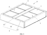
- FIG. 3 is a schematic structural diagram of a battery pack without a box cover according to an embodiment of this application.
- the first box body 1 may include a frame 12 and a cross beam 13, where the cross beam 13 is disposed within the frame 12.
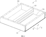
- FIG. 4 is a schematic structural diagram of a first box body in a battery pack according to an embodiment of this application. As shown in FIG. 4 , the frame 12 and the cross beam 13 in the first box body 1 form an accommodating area 14, and the battery cell 5 is accommodated in the accommodating area 4.
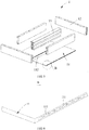
- FIG. 5 is a schematic exploded view of a first box body in a battery pack according to an embodiment of this application.
- FIG. 6 is an enlarged view of position B in FIG. 5 .
- the first box body may further include a base plate 11 for supporting the battery cell 5.
- the base plate 11 may be provided with a cooling passage 111, to cool the battery cell 5.
- the frame 12, the cross beam 13, and the base plate 11 may be fixedly connected by welding, so as to ensure overall rigidity and sealing performance of the first box body 1.
- a plurality of battery cells 5 may be provided, and the plurality of battery cells 5 are stacked along a length direction (Y) and a height direction (Z) of the first box body 1. Thermal runaway of one battery cell 5 may cause thermal runaway of adjacent battery cells 5, and such chain reaction may cause serious safety problems.
- the battery pack P and the apparatus provided in the embodiments of this application can resolve this technical problem.
- FIG. 7 is a schematic structural diagram of a cross beam of a first box body in a battery pack according to an embodiment of this application.
- FIG. 8 is a main cross-sectional view of a battery pack according to an embodiment of this application.
- FIG. 9 is an enlarged view of position A in FIG. 8 .
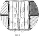
- FIG. 10 is a schematic diagram of working principles of a battery pack according to an embodiment of this application.
- FIG. 11 is a schematic diagram of a partial structure of a battery pack according to an embodiment of this application.
- the cross beam 13 of the first box body 1 has a hollow structure and is provided with an exhaust vent 132a (referring to FIG. 8 ), and the battery pack P further includes a baffle plate 15.
- the baffle plate 15 is connected to the cross beam 13 and seals the exhaust vent 132a.
- the baffle plate 15 is configured to exit a state of sealing the exhaust vent 132a when the explosion-proof valve 51 of the battery cell 5 bursts. In a normal working state (that is, the battery cell 5 is free of thermal runaway), the explosion-proof valve 51 does not burst.
- the baffle plate 15 seals the exhaust vent 132a, to prevent water vapor from entering the accommodating area 4 through the cross beam 13, thereby preventing short circuits of the battery cells 5.
- Both ends of the cross beam 13 may be fastened to the frame 12 by welding, to enhance a mechanical connection strength of the cross beam 13.
- a plurality of battery cells 5 may be provided, and explosion-proof valves 51 of the plurality of battery cells 5 may all face towards the same cross beam 13.
- explosion-proof valves 51 of battery cells 5 in two adjacent rows are disposed opposite each other and face towards the same cross beam 13.
- the bottom of the cross beam 13 may be provided with an open structure, so that an inside of the cross beam 13 can communicate with the outside, to discharge gas.
- a melting point of the baffle plate 15 may be set to be lower than a melting point of the cross beam 13.
- a wall thickness of the baffle plate 15 may be less than a wall thickness of the cross beam 13.
- the baffle plate 15 and the cross beam 13 may be integrally formed, for example, may be made of a same material through laser engraving. Because the wall thickness of the baffle plate 15 is less than the wall thickness of the cross beam 13, when thermal runaway occurs in the battery cell 5, the explosion-proof valve 51 of the battery cell 5 bursts, and the heat and air pressure that are released by the battery cell 5 act on the baffle plate 15 to make the baffle plate 15 blown or melted, so that the baffle plate 15 exits the state of sealing the exhaust vent 132a.
- the melting point of the baffle plate 15 is lower than the melting point of the cross beam 13, and the wall thickness of the baffle plate 15 is less than the wall thickness of the cross beam 13, so that when thermal runaway occurs in the battery cell 5, the baffle plate 15 more easily exits the state of sealing the exhaust vent 132a.
- the cross beam 13 includes a top plate 131 and two side plates 132, and the two side plates 132 are connected to two ends of the top plate 131, respectively.
- the side plates 132 may be integrally formed with the top plate 131 through punching, and the exhaust vents 132a may be provided in the side plates 132.
- the explosion-proof valve 51 of the battery cell 5 may face towards the cross beam 13, and the exhaust vent 132a is provided in the side plate 132 to make the exhaust vent 132a substantially aligned with the explosion-proof valve 51.
- the first box body 1 further includes a protective plate 16 disposed within the cross beam 13, and the protective plate 16 is located between the two side plates 132.
- the protective plate 16 With the protective plate 16 disposed between the two side plates 132, when thermal runaway occurs in a battery cell 5 in the battery pack P, an explosion-proof valve 51 of the battery cell 5 bursts, and the heat and the air pressure that are released by the battery cell 5 act on the baffle plate 15 to make the baffle plate 15 broken, so that the baffle plate 15 exits the state of sealing the exhaust vent 132a. The heat and the air pressure that are released by the battery cell 5 impinge on the protective plate 16. On the one hand, the protective plate 16 can guide the heat and gas to the ground below the first box body 1, and serve to protect the adjacent battery cells 5.
- the explosion-proof valves 51 of the two battery cells 5 are also disposed opposite each other. Disposition of the protective plate 16 can prevent the heat and air pressure released by the battery cell 5 in thermal runway from breaking through the side plate 132 and directly rushing to the opposite explosion-proof valve 51, resulting in safety problems.
- the battery cell 5 is provided in plurality, and the plurality of battery cells 5 are grouped into a first battery group 3 and a second battery group 4.
- the cross beam 13 is located between the first battery group 3 and the second battery group 4.
- the plurality of battery cells 5 are disposed flat in the first box body 1, and the explosion-proof valves 51 of the grouped battery cells 5 may all face towards the same cross beam 13, so that special treatment can be performed on the cross beam 13.
- the exhaust vent 132a may be provided in the side plate 132 of the cross beam 13, and the baffle plate 15 may be disposed at the exhaust vent 132a.
- the cross beam 13 is disposed between the first battery group 3 and the second battery group 4, so that the explosion-proof valves 51 of the battery cells 5 face towards the same cross beam 13.
- a corresponding baffle plate 15 on the cross beam 13 exits the state of sealing the exhaust vent 132a, to avoid thermal runaway in chain.
- a structure of the first box body 1 is simple, and all the cross beams 13 and the frame 12 do not require special treatment, relatively low in manufacturing costs.
- an exhaust vent 132a corresponding to an explosion-proof valve 51 of a battery cell 5 in the first battery group 3 is provided in one of the side plates 132; and an exhaust vent 132a corresponding to an explosion-proof valve 51 of a battery cell 5 in the second battery group 4 is provided in the other side plate 132.
- the two side plates 132 are each provided with exhaust vents 132a, so that each explosion-proof valve 51 in the two battery groups (the first battery group 3 and the second battery group 4) may correspond to one exhaust vent 132a and one baffle plate 15.
- the corresponding baffle plate 15 can come off the corresponding exhaust vent 132a, so that the heat and the air pressure that are released by the battery cell 5 in thermal runaway can be discharged in a timely manner, thereby avoiding thermal runaway of adjacent battery cells 5.
- the plurality of battery cells 5 are stacked along the length direction (Y) and the height direction (Z) of the first box body 1.
- the exhaust vent 132a is provided in plurality, and the plurality of exhaust vents 132a are arranged along the length direction (Y) and the height direction (Z).
- each explosion-proof valve 51 corresponds to one exhaust vent 132a, and a plurality of exhaust vents 132a are arranged in the length direction (Y).
- the battery cells 5 are stacked, and therefore, a plurality of exhaust vents 132a are arranged in the height direction (Z).
- the first box body 1 further includes a fastening member 17 disposed within the cross beam 13, and the fastening member 17 is connected to the protective plate 16, so that the protective plate 16 extends along the height direction (Z).
- the fastening member 17 is provided to make the protective plate 16 securely connected to the inside of the cross beam 13.
- the protective plate 16 extends along the height direction (Z), and may simultaneously correspond to a plurality of battery cells 5 in the height direction (Z), so that the plurality of battery cells 5 share one protective plate 16, featuring more overall and reliable protective effects and a simple structure.
- the fastening member 17 includes a first fastening plate 171 and a second fastening plate 172, and the protective plate 16 is sandwiched between the first fastening plate 171 and the second fastening plate 172.
- a first end of the first fastening plate 171 is connected to the top plate 131, and a first end of the second fastening plate 172 is connected to the top plate 131.
- a second end of the first fastening plate 171 is connected to a second end of the second fastening plate 172.
- the first fastening plate 171, the second fastening plate 172, and the top plate 131 form a cavity 18, and the protective plate 16 is fastened in the cavity 18.
- a first end of the protective plate 16 may be fastened to the first fastening plate 171 and the second fastening plate 172 by welding, and a second end of the protective plate 16 may be fastened to the top plate 131 of the cross beam 13 by welding.
- the first fastening plate 171, the second fastening plate 172, and the top plate 131 of the cross beam 13 form an inverted triangle cavity 18.
- the inverted triangle cavity 18 can serve to support the protective plate 16, so as to prevent the protective plate 16 from being impinged and detaching.
- the first fastening plate 171, the top plate 131, and one side plate 132 can form a first passage 133
- the second fastening plate 172, the top plate 131, and the other side plate 132 can form a second passage 134.
- FIG. 11 shows the state in which the baffle plate 15 comes off the exhaust vent 132a.
- the protective plate 16 is still fixed in the cross beam 13 and has strong impact resistance, thereby not only guiding a discharge direction of the heat and the gas that are released by the battery cell 5, but also avoiding thermal runaway of the adjacent battery cells 5.
- the protective plate 16 is a mica plate, and the mica plate has a relatively high melting point.
- the protective plate 16 is not blown or broken down even if relatively high heat is emitted from the exhaust vent 132a, thereby ensuring that the heat and gas released by the battery cell 5 in thermal runaway is not ejected to the adjacent battery cells 5 on the opposite side to cause safety problems.
- the first box body 1 includes a base plate 11, and as described above, the base plate 11 is used to support the battery cell 5.
- Both the frame 12 and the cross beam 13 may be connected to one side of the base plate 11, and the base plate 11 may be provided with a water cooling passage 111.
- the water cooling passage 111 may be elongated, and is provided inside the base plate 11 to match an arrangement direction of the battery cells 5. During charging and discharging of the battery cell 5, the battery cell 5 generates heat to some extent, and then the battery cell 5 can be cooled through the water cooling passage 111 provided in the base plate 11.
- the base plate 11 is provided with an exhaust passage 112 communicating with the inside of the cross beam 13, and the inside of the cross beam 13 communicates with the outside of the first box body 1 through the exhaust passage 112.
- the exhaust passage 112 communicating with the inside of the cross beam 13.
- an explosion-proof valve 51 of the battery cell 5 bursts, so that the baffle plate 15 exits the state of sealing the exhaust vent 132a.
- the gas released by the battery cell 5 in thermal runaway may be discharged into the cross beam 13 and enters the inside of the cross beam 13.
- the gas released by the battery cell 5 may be discharged to the outside of the battery pack P through the first passage 133 and the second passage 134, and the exhaust passage 112 that is provided at the bottom of the base plate 11.
- the exhaust passage 112 and the cross beam 13 extend along the length direction (Y) of the first box body 1.
- the exhaust passage 112 corresponds to the cross beam 13, and is provided in a manner of arranging the battery cells 5 along the length direction (Y). After the gas released by the battery cell 5 in thermal runaway enters the inside of the cross beam 13, the high-temperature gas can be fully released because the exhaust passage 112 extends in the length direction (Y), thereby avoiding chain reaction.
Landscapes
- Chemical & Material Sciences (AREA)
- Chemical Kinetics & Catalysis (AREA)
- Electrochemistry (AREA)
- General Chemical & Material Sciences (AREA)
- Engineering & Computer Science (AREA)
- Aviation & Aerospace Engineering (AREA)
- Battery Mounting, Suspending (AREA)
Abstract
Description
- This application claims priority to
Chinese Patent Application No.201911085794.5, filed with Chinese Patent Office on November 8th, 2019 - Embodiments of this application relate to the technical field of energy storage devices, and in particular to a battery pack and an apparatus.
- A battery pack serves an important part of a new energy vehicle, and therefore safety performance of the battery pack is very important. A battery pack includes a first box body and a plurality of battery cells accommodated in the first box body. The battery cell has an explosion-proof valve. After thermal runaway occurs in the battery cell, the explosion-proof valve bursts to release internal air pressure and heat from the battery cell.
- However, if thermal runaway occurs in one battery cell, heat released from an explosion-proof valve of that battery cell will lead to chain runaway of other battery cells. Therefore, it is necessary to design a new battery pack to prevent thermal runaway of one battery cell from affecting other battery cells.
- This application provides a battery pack and an apparatus, in an attempt to resolve the foregoing prior-art problem and improve safety performance of batteries.
- A first aspect of this application provides a battery pack, including:
- a first box body, including a frame and a cross beam, where the cross beam is disposed within the frame, and the cross beam has a hollow structure and is provided with an exhaust vent;
- a baffle plate, connected to the cross beam and sealing the exhaust vent; and
- a battery cell, accommodated in the first box body and including an explosion-proof valve, where the explosion-proof valve faces towards the baffle plate.
- The baffle plate is configured to exit a state of sealing the exhaust vent when the explosion-proof valve of the battery cell bursts.
- In this way, on the one hand, air pressure released by the battery cell can be discharged into the cross beam, thereby reducing internal air pressure of the first box body; on the other hand, heat released by the battery cell is not directly discharged towards other battery cells to avoid thermal runaway of other adjacent battery cells, thereby resolving a safety problem of a battery pack in the prior art and improving safety performance of the battery pack.
- In one possible implementation, a melting point of the baffle plate is lower than a melting point of the cross beam; and/or
a wall thickness of the baffle plate is less than a wall thickness of the cross beam. - In a possible implementation, the cross beam includes a top plate and two side plates; the two side plates are connected to two ends of the top plate, respectively; and the exhaust vent is provided in the side plate.
- In a possible implementation, the first box body further includes a protective plate disposed within the cross beam, and the protective plate is located between the two side plates.
- On the one hand, the protective plate can guide heat and gas to the ground below the first box body, and serve to protect adjacent battery cells. On the other hand, when two battery cells are disposed opposite each other, explosion-proof valves of the two battery cells are also disposed opposite each other. Disposition of the protective plate can prevent heat and air pressure released by a battery cell in thermal runway from breaking through the side plate and directly rushing to the opposite explosion-proof valve, resulting in safety problems.
- In a possible implementation, the battery cell is provided in plurality, the plurality of battery cells is grouped into a first battery group and a second battery group, and the cross beam is located between the first battery group and the second battery group.
- In a possible implementation, the exhaust vent corresponding to the explosion-proof valve of the battery cell of the first battery group is provided in one of the side plates; and
the exhaust vent corresponding to the explosion-proof valve of the battery cell of the second battery group is provided in the other side plate. - In a possible implementation, the plurality of battery cells are stacked along a length direction (Y) and a height direction (Z) of the first box body; and
the exhaust vent is provided in plurality, and the plurality of exhaust vents are arranged along the length direction Y and the height direction Z. - In a possible implementation, the first box body further includes a fastening member disposed within the cross beam, and the fastening member is connected to the protective plate, so that the protective plate extends along the height direction (Z). The fastening member is provided to make the protective plate securely connected to an inside of the cross beam.
- In a possible implementation, the fastening member includes a first fastening plate and a second fastening plate; and the protective plate is sandwiched between the first fastening plate and the second fastening plate.
- In a possible implementation, the protective plate is a mica plate. The mica plate has a relatively high melting point. The protective plate is not blown or broken down even if relatively high heat is emitted from the exhaust vent, thereby ensuring that the heat and gas released by the battery cell in thermal runaway is not ejected to the adjacent battery cells on the opposite side to cause safety problems.
- In a possible implementation, the first box body includes a base plate.
- Both the frame and the cross beam are connected to one side of the base plate. The base plate is used to support the battery cell. The frame, the cross beam, and the base plate may be fixedly connected by welding, so as to ensure overall rigidity and sealing performance of the first box body.
- In a possible implementation, the base plate is provided with an exhaust passage communicating with the inside of the cross beam.
- The inside of the cross beam communicates with an outside of the first box body through the exhaust passage. In a possible implementation, both the exhaust passage and the cross beam extend along the length direction (Y) of the first box body.
- A second aspect of this application provides an apparatus, including:
the battery pack described above, where the battery pack is configured to provide electric energy. - The technical solutions of this application can achieve the following beneficial effects:
- According to the battery pack and the apparatus that are provided in this application, the exhaust vent is provided in the cross beam of the first box body in the battery pack, and the baffle plate is provided at the exhaust vent. When thermal runaway occurs in a battery cell, an explosion-proof valve of the battery cell bursts, to make the baffle plate exit the state of sealing the exhaust vent. On the one hand, air pressure released by the battery cell may be discharged into the cross beam, thereby reducing internal air pressure of the first box body; on the other hand, heat released by the battery cell is not directly discharged towards other battery cells to avoid thermal runaway of other adjacent battery cells, thereby resolving a safety problem of a battery pack in the prior art and improving safety performance of the battery pack.
- It should be understood that the foregoing general description and the following detailed description are only exemplary and are not intended to limit this application.
- To describe the technical solutions in the specific implementations of this application or in the prior art more clearly, the following briefly describes the accompanying drawings required for describing the specific implementations or the prior art. Apparently, the accompanying drawings in the following description show merely some implementations of this application, and a person of ordinary skill in the art may still derive other drawings from these accompanying drawings without creative efforts.
-
FIG. 1 is a schematic structural diagram of an apparatus according to an embodiment of this application. -
FIG. 2 is a schematic exploded view of a battery pack according to an embodiment of this application. -
FIG. 3 is a schematic structural diagram of a battery pack without a box cover according to an embodiment of this application. -
FIG. 4 is a schematic structural diagram of a first box body in a battery pack according to an embodiment of this application. -
FIG. 5 is a schematic exploded view of a first box body in a battery pack according to an embodiment of this application. -
FIG. 6 is an enlarged view of position B inFIG. 5 . -
FIG. 7 is a schematic structural diagram of a cross beam of a first box body in a battery pack according to an embodiment of this application. -
FIG. 8 is a main cross-sectional view of a battery pack according to an embodiment of this application. -
FIG. 9 is an enlarged view of position A inFIG. 8 . -
FIG. 10 is a schematic diagram of working principles of a battery pack according to an embodiment of this application. -
FIG. 11 is a schematic diagram of a partial structure of a battery pack according to an embodiment of this application. -
- P. battery pack;
- 1. first box body;
- 11. base plate;
- 111. water cooling passage;
- 112. exhaust passage;
- 12. frame;
- 13. cross beam;
- 131. top plate;
- 132. side plate;
132a. exhaust vent; - 133. first passage;
- 134. second passage;
- 14. accommodating area;
- 15. baffle plate;
- 16. protective plate;
- 17. fastening member;
- 171. first fastening plate;
- 172. second fastening plate;
- 18. cavity;
- 11. base plate;
- 2. upper box cover;
- 3. first battery group;
- 4. second battery group;
- 5. battery cell; and
- 51. explosion-proof valve.
- The accompanying drawings herein are incorporated into this specification and form a part of this specification, illustrate the embodiments conforming to this application, and are intended to explain the principles of this application together with the specification.
- The following clearly and completely describes the technical solutions in this application with reference to the accompanying drawings. Apparently, the described embodiments are some but not all of the embodiments of this application. All other embodiments obtained by persons of ordinary skill in the art based on the embodiments of this application without creative efforts shall fall within the protection scope of this application.
- The terms used in the embodiments of this application are merely intended to describe specific embodiments, but not intended to limit this application. The singular forms of "a", "the", and "said" used in the embodiments of this application and the appended claims are also intended to include most forms unless other meanings are clearly represented in the context.
- It should be understood that the term "and/or" used in this specification describes an association relationship for describing associated objects and represents that three relationships may exist. For example, A and/or B may represent the following three cases: A alone, both A and B, and B alone. In addition, the symbol "/" in this specification generally represents an "or" relationship between associated objects.
- It should be noted that the terms such as "upper", "lower", "left", and "right" described in the embodiments of this application are described from angles shown in the figures, and should not be construed as a limitation on the embodiments of this application. In addition, in the context, it should also be understood that when a component is described as being connected "on" or "under" another component, the component may be directly connected "on" or "under" the another component, or may be indirectly connected "on" or "under" another component through an intermediate component.
-
FIG. 1 is a schematic structural diagram of an apparatus according to an embodiment of this application. As shown inFIG. 1 , this embodiment of this application provides an apparatus. The apparatus may include a vehicle, a ship, a small aircraft, and other mobile devices.FIG. 1 uses the vehicle as an example. The vehicle may include a battery pack P and a vehicle body. The battery pack P is disposed in the vehicle body. The vehicle body is further provided with a drive motor, and the drive motor is electrically connected to the battery pack P. The battery pack P provides electric energy to the drive motor. The drive motor is connected to wheels on the vehicle body through a transmission mechanism to drive travel of the vehicle. In a specific embodiment, the battery pack P may be disposed at the bottom of the vehicle body. -
FIG. 2 is a schematic exploded view of a battery pack according to an embodiment of this application. As shown inFIG. 2 , this embodiment of this application provides a battery pack, including afirst box body 1, anupper box cover 2, and abattery cell 5. Thebattery cell 5 is accommodated in thefirst box body 1, and theupper box cover 2 is fastened to thefirst box body 1 to enclose thebattery cell 5 in thefirst box body 1. -
FIG. 3 is a schematic structural diagram of a battery pack without a box cover according to an embodiment of this application. As shown inFIG. 3 , thefirst box body 1 may include aframe 12 and across beam 13, where thecross beam 13 is disposed within theframe 12.FIG. 4 is a schematic structural diagram of a first box body in a battery pack according to an embodiment of this application. As shown inFIG. 4 , theframe 12 and thecross beam 13 in thefirst box body 1 form anaccommodating area 14, and thebattery cell 5 is accommodated in theaccommodating area 4. -
FIG. 5 is a schematic exploded view of a first box body in a battery pack according to an embodiment of this application.FIG. 6 is an enlarged view of position B inFIG. 5 . As shown inFIG. 5 and FIG. 6 , the first box body may further include abase plate 11 for supporting thebattery cell 5. Thebase plate 11 may be provided with acooling passage 111, to cool thebattery cell 5. - The
frame 12, thecross beam 13, and thebase plate 11 may be fixedly connected by welding, so as to ensure overall rigidity and sealing performance of thefirst box body 1. - Referring to
FIG. 2 andFIG. 3 , in this embodiment, a plurality ofbattery cells 5 may be provided, and the plurality ofbattery cells 5 are stacked along a length direction (Y) and a height direction (Z) of thefirst box body 1. Thermal runaway of onebattery cell 5 may cause thermal runaway ofadjacent battery cells 5, and such chain reaction may cause serious safety problems. The battery pack P and the apparatus provided in the embodiments of this application can resolve this technical problem. -
FIG. 7 is a schematic structural diagram of a cross beam of a first box body in a battery pack according to an embodiment of this application.FIG. 8 is a main cross-sectional view of a battery pack according to an embodiment of this application.FIG. 9 is an enlarged view of position A inFIG. 8 .FIG. 10 is a schematic diagram of working principles of a battery pack according to an embodiment of this application.FIG. 11 is a schematic diagram of a partial structure of a battery pack according to an embodiment of this application. - As shown in
FIG. 7 to FIG. 11 , in the battery pack P provided in the embodiments of this application, thecross beam 13 of thefirst box body 1 has a hollow structure and is provided with anexhaust vent 132a (referring toFIG. 8 ), and the battery pack P further includes abaffle plate 15. Thebaffle plate 15 is connected to thecross beam 13 and seals theexhaust vent 132a. Thebaffle plate 15 is configured to exit a state of sealing theexhaust vent 132a when the explosion-proof valve 51 of thebattery cell 5 bursts. In a normal working state (that is, thebattery cell 5 is free of thermal runaway), the explosion-proof valve 51 does not burst. In this case, thebaffle plate 15 seals theexhaust vent 132a, to prevent water vapor from entering theaccommodating area 4 through thecross beam 13, thereby preventing short circuits of thebattery cells 5. - Both ends of the
cross beam 13 may be fastened to theframe 12 by welding, to enhance a mechanical connection strength of thecross beam 13. There may be one or more cross beams 13. When there is onecross beam 13, a plurality ofbattery cells 5 may be provided, and explosion-proof valves 51 of the plurality ofbattery cells 5 may all face towards thesame cross beam 13. When a plurality of cross beams 13 are provided, explosion-proof valves 51 ofbattery cells 5 in two adjacent rows are disposed opposite each other and face towards thesame cross beam 13. - The bottom of the
cross beam 13 may be provided with an open structure, so that an inside of thecross beam 13 can communicate with the outside, to discharge gas. - When thermal runaway occurs in a
battery cell 5 in the battery pack P, an explosion-proof valve 51 of thebattery cell 5 bursts, so that thebaffle plate 15 exits the state of sealing theexhaust vent 132a. On the one hand, air pressure released by thebattery cell 5 can be discharged into thecross beam 13, to reduce internal air pressure of theaccommodating area 4; on the other hand, heat released by thebattery cell 5 is not directly discharged towardsother battery cells 5, to avoid thermal runaway of the otheradjacent battery cells 5, thereby resolving a safety problem of a battery pack in the prior art and improving safety performance of the battery pack. - As a possible implementation, a melting point of the
baffle plate 15 may be set to be lower than a melting point of thecross beam 13. When thermal runaway occurs in abattery cell 5, an explosion-proof valve 51 of thebattery cell 5 bursts, and heat and air pressure that are released by thebattery cell 5 act on thebaffle plate 15 to make thebaffle plate 15 blown or melted, so that thebaffle plate 15 exits the state of sealing theexhaust vent 132a. - As another possible implementation, a wall thickness of the
baffle plate 15 may be less than a wall thickness of thecross beam 13. In this embodiment, thebaffle plate 15 and thecross beam 13 may be integrally formed, for example, may be made of a same material through laser engraving. Because the wall thickness of thebaffle plate 15 is less than the wall thickness of thecross beam 13, when thermal runaway occurs in thebattery cell 5, the explosion-proof valve 51 of thebattery cell 5 bursts, and the heat and air pressure that are released by thebattery cell 5 act on thebaffle plate 15 to make thebaffle plate 15 blown or melted, so that thebaffle plate 15 exits the state of sealing theexhaust vent 132a. - As yet another possible implementation, the melting point of the
baffle plate 15 is lower than the melting point of thecross beam 13, and the wall thickness of thebaffle plate 15 is less than the wall thickness of thecross beam 13, so that when thermal runaway occurs in thebattery cell 5, thebaffle plate 15 more easily exits the state of sealing theexhaust vent 132a. - As shown in
FIG. 7 , in one possible implementation, thecross beam 13 includes atop plate 131 and twoside plates 132, and the twoside plates 132 are connected to two ends of thetop plate 131, respectively. Specifically, theside plates 132 may be integrally formed with thetop plate 131 through punching, and theexhaust vents 132a may be provided in theside plates 132. For thebattery cell 5 disposed flat, the explosion-proof valve 51 of thebattery cell 5 may face towards thecross beam 13, and theexhaust vent 132a is provided in theside plate 132 to make theexhaust vent 132a substantially aligned with the explosion-proof valve 51. In this way, when thermal runaway occurs in abattery cell 5 in the battery pack P, the explosion-proof valve 51 of thebattery cell 5 bursts, and the heat and the air pressure that are released by thebattery cell 5 act on thebaffle plate 15 to make thebaffle plate 15 quickly broken in response to the thermal runaway, so that thebaffle plate 15 exits the state of sealing theexhaust vent 132a. - As shown in
FIG. 6 to FIG. 8 , in one possible implementation, thefirst box body 1 further includes aprotective plate 16 disposed within thecross beam 13, and theprotective plate 16 is located between the twoside plates 132. - With the
protective plate 16 disposed between the twoside plates 132, when thermal runaway occurs in abattery cell 5 in the battery pack P, an explosion-proof valve 51 of thebattery cell 5 bursts, and the heat and the air pressure that are released by thebattery cell 5 act on thebaffle plate 15 to make thebaffle plate 15 broken, so that thebaffle plate 15 exits the state of sealing theexhaust vent 132a. The heat and the air pressure that are released by thebattery cell 5 impinge on theprotective plate 16. On the one hand, theprotective plate 16 can guide the heat and gas to the ground below thefirst box body 1, and serve to protect theadjacent battery cells 5. On the other hand, when the twobattery cells 5 are disposed opposite each other, the explosion-proof valves 51 of the twobattery cells 5 are also disposed opposite each other. Disposition of theprotective plate 16 can prevent the heat and air pressure released by thebattery cell 5 in thermal runway from breaking through theside plate 132 and directly rushing to the opposite explosion-proof valve 51, resulting in safety problems. - Specifically, referring to
FIG. 8 andFIG. 9 , in a specific implementation, thebattery cell 5 is provided in plurality, and the plurality ofbattery cells 5 are grouped into afirst battery group 3 and asecond battery group 4. Thecross beam 13 is located between thefirst battery group 3 and thesecond battery group 4. - In this embodiment, the plurality of
battery cells 5 are disposed flat in thefirst box body 1, and the explosion-proof valves 51 of the groupedbattery cells 5 may all face towards thesame cross beam 13, so that special treatment can be performed on thecross beam 13. As shown inFIG. 9 , theexhaust vent 132a may be provided in theside plate 132 of thecross beam 13, and thebaffle plate 15 may be disposed at theexhaust vent 132a. - The
cross beam 13 is disposed between thefirst battery group 3 and thesecond battery group 4, so that the explosion-proof valves 51 of thebattery cells 5 face towards thesame cross beam 13. When thermal runaway occurs, acorresponding baffle plate 15 on thecross beam 13 exits the state of sealing theexhaust vent 132a, to avoid thermal runaway in chain. In this embodiment, a structure of thefirst box body 1 is simple, and all the cross beams 13 and theframe 12 do not require special treatment, relatively low in manufacturing costs. - In a specific implementation, an
exhaust vent 132a corresponding to an explosion-proof valve 51 of abattery cell 5 in thefirst battery group 3 is provided in one of theside plates 132; and anexhaust vent 132a corresponding to an explosion-proof valve 51 of abattery cell 5 in thesecond battery group 4 is provided in theother side plate 132. - In this embodiment, the two
side plates 132 are each provided withexhaust vents 132a, so that each explosion-proof valve 51 in the two battery groups (thefirst battery group 3 and the second battery group 4) may correspond to oneexhaust vent 132a and onebaffle plate 15. When any one of the explosion-proof valves 51 bursts, the correspondingbaffle plate 15 can come off the correspondingexhaust vent 132a, so that the heat and the air pressure that are released by thebattery cell 5 in thermal runaway can be discharged in a timely manner, thereby avoiding thermal runaway ofadjacent battery cells 5. - In a specific implementation, the plurality of
battery cells 5 are stacked along the length direction (Y) and the height direction (Z) of thefirst box body 1. Theexhaust vent 132a is provided in plurality, and the plurality ofexhaust vents 132a are arranged along the length direction (Y) and the height direction (Z). - Referring to
FIG. 9 , each explosion-proof valve 51 corresponds to oneexhaust vent 132a, and a plurality ofexhaust vents 132a are arranged in the length direction (Y). In the height direction (Z), thebattery cells 5 are stacked, and therefore, a plurality ofexhaust vents 132a are arranged in the height direction (Z). - Referring to
FIG. 7 andFIG. 9 , in a specific implementation, thefirst box body 1 further includes afastening member 17 disposed within thecross beam 13, and thefastening member 17 is connected to theprotective plate 16, so that theprotective plate 16 extends along the height direction (Z). - The
fastening member 17 is provided to make theprotective plate 16 securely connected to the inside of thecross beam 13. Theprotective plate 16 extends along the height direction (Z), and may simultaneously correspond to a plurality ofbattery cells 5 in the height direction (Z), so that the plurality ofbattery cells 5 share oneprotective plate 16, featuring more overall and reliable protective effects and a simple structure. - In a specific implementation, as shown in
FIG. 9 , thefastening member 17 includes afirst fastening plate 171 and asecond fastening plate 172, and theprotective plate 16 is sandwiched between thefirst fastening plate 171 and thesecond fastening plate 172. - A first end of the
first fastening plate 171 is connected to thetop plate 131, and a first end of thesecond fastening plate 172 is connected to thetop plate 131. A second end of thefirst fastening plate 171 is connected to a second end of thesecond fastening plate 172. Thefirst fastening plate 171, thesecond fastening plate 172, and thetop plate 131 form acavity 18, and theprotective plate 16 is fastened in thecavity 18. - Specifically, a first end of the
protective plate 16 may be fastened to thefirst fastening plate 171 and thesecond fastening plate 172 by welding, and a second end of theprotective plate 16 may be fastened to thetop plate 131 of thecross beam 13 by welding. - In this embodiment, the
first fastening plate 171, thesecond fastening plate 172, and thetop plate 131 of thecross beam 13 form aninverted triangle cavity 18. Once thebaffle plate 15 comes off theexhaust vent 132a, theinverted triangle cavity 18 can serve to support theprotective plate 16, so as to prevent theprotective plate 16 from being impinged and detaching. - In this embodiment, the
first fastening plate 171, thetop plate 131, and oneside plate 132 can form afirst passage 133, and thesecond fastening plate 172, thetop plate 131, and theother side plate 132 can form asecond passage 134. When thebaffle plate 15 comes off theexhaust vent 132a, the heat and the gas that are released by thebattery cell 5 can be discharged to an outside of thefirst box body 1 through thefirst passage 133 or thesecond passage 134, as shown inFIG. 9 andFIG. 10 . -
FIG. 11 shows the state in which thebaffle plate 15 comes off theexhaust vent 132a. At that time, theprotective plate 16 is still fixed in thecross beam 13 and has strong impact resistance, thereby not only guiding a discharge direction of the heat and the gas that are released by thebattery cell 5, but also avoiding thermal runaway of theadjacent battery cells 5. - In a specific implementation, the
protective plate 16 is a mica plate, and the mica plate has a relatively high melting point. Theprotective plate 16 is not blown or broken down even if relatively high heat is emitted from theexhaust vent 132a, thereby ensuring that the heat and gas released by thebattery cell 5 in thermal runaway is not ejected to theadjacent battery cells 5 on the opposite side to cause safety problems. - In a specific implementation, the
first box body 1 includes abase plate 11, and as described above, thebase plate 11 is used to support thebattery cell 5. Both theframe 12 and thecross beam 13 may be connected to one side of thebase plate 11, and thebase plate 11 may be provided with awater cooling passage 111. Thewater cooling passage 111 may be elongated, and is provided inside thebase plate 11 to match an arrangement direction of thebattery cells 5. During charging and discharging of thebattery cell 5, thebattery cell 5 generates heat to some extent, and then thebattery cell 5 can be cooled through thewater cooling passage 111 provided in thebase plate 11. - In a specific implementation, as shown in
FIG. 5 , thebase plate 11 is provided with anexhaust passage 112 communicating with the inside of thecross beam 13, and the inside of thecross beam 13 communicates with the outside of thefirst box body 1 through theexhaust passage 112. - The
exhaust passage 112 communicating with the inside of thecross beam 13. When thermal runaway occurs in abattery cell 5 in the battery pack P, an explosion-proof valve 51 of thebattery cell 5 bursts, so that thebaffle plate 15 exits the state of sealing theexhaust vent 132a. The gas released by thebattery cell 5 in thermal runaway may be discharged into thecross beam 13 and enters the inside of thecross beam 13. Specifically, the gas released by thebattery cell 5 may be discharged to the outside of the battery pack P through thefirst passage 133 and thesecond passage 134, and theexhaust passage 112 that is provided at the bottom of thebase plate 11. - In a specific implementation, referring to
FIG. 4 andFIG. 5 , theexhaust passage 112 and thecross beam 13 extend along the length direction (Y) of thefirst box body 1. Theexhaust passage 112 corresponds to thecross beam 13, and is provided in a manner of arranging thebattery cells 5 along the length direction (Y). After the gas released by thebattery cell 5 in thermal runaway enters the inside of thecross beam 13, the high-temperature gas can be fully released because theexhaust passage 112 extends in the length direction (Y), thereby avoiding chain reaction. - The foregoing descriptions are merely embodiments of this application, but are not intended to limit this application. Persons skilled in the art understand that this application may have various modifications and variations. Any modification, equivalent replacement, and improvement made without departing from the spirit and principle of this application shall fall within the protection scope of this application.
Claims (14)
- A battery pack, comprising:a first box body (1), comprising a frame (12) and a cross beam (13), wherein the cross beam (13) is disposed within the frame (12), and the cross beam (13) has a hollow structure and is provided with an exhaust vent (132a);a baffle plate (15), connected to the cross beam (13) and sealing the exhaust vent (132a); anda battery cell (5), accommodated in the first box body (1) and comprising an explosion-proof valve (51), wherein the explosion-proof valve (51) faces towards the baffle plate (15); andthe baffle plate (15) is configured to exit a state of sealing the exhaust vent (132a) when the explosion-proof valve (51) of the battery cell (5) bursts.
- The battery pack according to claim 1, wherein a melting point of the baffle plate (15) is lower than a melting point of the cross beam (13); and/or
a wall thickness of the baffle plate (15) is less than a wall thickness of the cross beam (13). - The battery pack according to claim 1 or 2, wherein the cross beam (13) comprises a top plate (131) and two side plates (132), and the two side plates (132) are connected to two ends of the top plate (131), respectively; and
the exhaust vent (132a) is provided in the side plate (132). - The battery pack according to claim 3, wherein the first box body (1) further comprises a protective plate (16) disposed within the cross beam (13), and the protective plate (16) is located between the two side plates (132).
- The battery pack according to claim 4, wherein the battery cell (5) is provided in plurality, the plurality of battery cells (5) are grouped into a first battery group (3) and a second battery group (4), and the cross beam (13) is located between the first battery group (3) and the second battery group (4).
- The battery pack according to claim 5, wherein the exhaust vent (132a) corresponding to the explosion-proof valve (51) of the battery cell (5) of the first battery group (3) is provided in one of the side plates (132); and
the exhaust vent (132a) corresponding to the explosion-proof valve (51) of the battery cell (5) of the second battery group (4) is provided in the other side plate (132). - The battery pack according to claim 5 or 6, wherein the plurality of battery cells (5) are stacked along a length direction (Y) and a height direction (Z) of the first box body (1); and
the exhaust vent (132a) is provided in plurality, and the plurality of exhaust vents (132a) are arranged along the length direction (Y) and the height direction (Z). - The battery pack according to any one of claims 4 to 7, wherein the first box body (1) further comprises a fastening member (17) disposed within the cross beam (13), and the fastening member (17) is connected to the protective plate (16), so that the protective plate (16) extends along the height direction (Z).
- The battery pack according to claim 8, wherein the fastening member (17) comprises a first fastening plate (171) and a second fastening plate (172); and the protective plate (16) is sandwiched between the first fastening plate (171) and the second fastening plate (172).
- The battery pack according to any one of claims 4 to 9, wherein the protective plate (16) is a mica plate.
- The battery pack according to any one of claims 1 to 10, wherein the first box body (1) comprises a base plate (11); and
the frame (12) and the cross beam (13) are both connected to one side of the base plate (11). - The battery pack according to claim 11, whereinthe base plate (11) is provided with an exhaust passage (112) communicating with an inside of the cross beam (13); andthe inside of the cross beam (13) communicates with an outside of the first box body (1) through the exhaust passage (112).
- The battery pack according to claim 12, wherein both the exhaust passage (112) and the cross beam (13) extend along the length direction (Y) of the first box body (1).
- An apparatus, comprising:
the battery pack according to any one of claims 1 to 13, wherein the battery pack is configured to provide electric energy.
Applications Claiming Priority (2)
| Application Number | Priority Date | Filing Date | Title |
|---|---|---|---|
| CN201911085794.5A CN112331992B (en) | 2019-11-08 | 2019-11-08 | Battery pack and device |
| PCT/CN2020/118765 WO2021088570A1 (en) | 2019-11-08 | 2020-09-29 | Battery pack and apparatus |
Publications (3)
| Publication Number | Publication Date |
|---|---|
| EP3926747A1 true EP3926747A1 (en) | 2021-12-22 |
| EP3926747A4 EP3926747A4 (en) | 2022-06-08 |
| EP3926747B1 EP3926747B1 (en) | 2024-04-17 |
Family
ID=74319691
Family Applications (1)
| Application Number | Title | Priority Date | Filing Date |
|---|---|---|---|
| EP20883829.2A Active EP3926747B1 (en) | 2019-11-08 | 2020-09-29 | Battery pack and apparatus |
Country Status (5)
| Country | Link |
|---|---|
| US (1) | US12278387B2 (en) |
| EP (1) | EP3926747B1 (en) |
| CN (1) | CN112331992B (en) |
| HU (1) | HUE067007T2 (en) |
| WO (1) | WO2021088570A1 (en) |
Cited By (15)
| Publication number | Priority date | Publication date | Assignee | Title |
|---|---|---|---|---|
| CN116598612A (en) * | 2023-05-17 | 2023-08-15 | 苏州光宝科技股份有限公司 | An explosion-proof combustion battery test box and test equipment |
| EP4231399A1 (en) * | 2022-02-17 | 2023-08-23 | Volvo Car Corporation | Structural battery pack cell signal and conversion pass-through |
| KR20230127899A (en) * | 2022-02-25 | 2023-09-01 | 프라임 플래닛 에너지 앤드 솔루션즈 가부시키가이샤 | Battery pack |
| JP2023124436A (en) * | 2022-02-25 | 2023-09-06 | プライムプラネットエナジー&ソリューションズ株式会社 | battery pack |
| DE102022117284A1 (en) * | 2022-07-12 | 2024-01-18 | Boge Elastmetall Gmbh | High-voltage storage |
| EP4343906A1 (en) * | 2022-09-26 | 2024-03-27 | SK On Co., Ltd. | Battery module |
| EP4235922A4 (en) * | 2022-01-12 | 2024-04-17 | Contemporary Amperex Technology Co., Limited | BOX FOR BATTERY, BATTERY, POWER CONSUMPTION DEVICE AND METHOD AND DEVICE FOR PRODUCING A BOX |
| EP4239769A3 (en) * | 2022-03-04 | 2024-06-19 | SK On Co., Ltd. | Battery pack |
| JP2024531304A (en) * | 2022-06-03 | 2024-08-29 | エルジー エナジー ソリューション リミテッド | Battery pack |
| EP4576367A1 (en) * | 2023-12-21 | 2025-06-25 | Volvo Truck Corporation | Electrical storage system with gas venting arrangement |
| US12374752B2 (en) | 2021-02-08 | 2025-07-29 | Sk On Co., Ltd. | Battery pack |
| GB2642714A (en) * | 2024-07-18 | 2026-01-21 | Jaguar Land Rover Ltd | Vehicle battery enclosure |
| GB2642713A (en) * | 2024-07-18 | 2026-01-21 | Jaguar Land Rover Ltd | Vehicle battery enclosure |
| EP4632914A4 (en) * | 2022-12-07 | 2026-04-15 | Panasonic Ip Man Co Ltd | BATTERY PACK |
| EP4648198A4 (en) * | 2023-01-05 | 2026-04-22 | Lg Energy Solution Ltd | BATTERY BLOCK |
Families Citing this family (61)
| Publication number | Priority date | Publication date | Assignee | Title |
|---|---|---|---|---|
| WO2018022964A1 (en) | 2016-07-29 | 2018-02-01 | Crynamt Management Llc | Battery packs having structural members for improving thermal management |
| US11757149B1 (en) | 2016-09-20 | 2023-09-12 | Apple Inc. | Battery liquid quench system and methods of manufacture thereof |
| US11870092B1 (en) | 2017-02-01 | 2024-01-09 | Apple Inc. | On-board vent gas abatement |
| US11469471B1 (en) | 2018-02-02 | 2022-10-11 | Apple Inc. | Battery pack heat dispensing systems |
| US11764431B2 (en) | 2020-10-22 | 2023-09-19 | Apple Inc. | Battery pack structures and systems |
| CN116368659A (en) | 2021-02-09 | 2023-06-30 | 宁德时代新能源科技股份有限公司 | Battery, electrical device, method for producing battery, and device for producing battery |
| CN115966823A (en) * | 2021-05-14 | 2023-04-14 | 中创新航科技股份有限公司 | Battery pack, assembly process of battery pack and vehicle |
| KR102821851B1 (en) * | 2021-06-02 | 2025-06-16 | 주식회사 엘지에너지솔루션 | Battery Pack, and Vehicle Including the Same |
| GB2607925B (en) * | 2021-06-16 | 2024-06-19 | Rolls Royce Plc | Aircraft battery systems |
| KR102929568B1 (en) * | 2021-06-17 | 2026-02-20 | 주식회사 엘지에너지솔루션 | Battery module and battery pack including the same and vehicle including the same |
| KR20220170188A (en) * | 2021-06-22 | 2022-12-29 | 주식회사 엘지에너지솔루션 | Battery module and battery pack including the same |
| CN113540615B (en) * | 2021-06-28 | 2026-04-07 | 长城汽车股份有限公司 | A battery pack lower housing, a battery pack and a vehicle |
| PL4152478T3 (en) | 2021-07-29 | 2025-05-26 | Contemporary Amperex Technology (Hong Kong) Limited | BATTERY, DEVICE FOR USING ENERGY, METHOD OF PREPARING A BATTERY AND APPARATUS FOR PREPARING A BATTERY |
| KR20230027685A (en) * | 2021-08-19 | 2023-02-28 | 주식회사 엘지에너지솔루션 | Battery module and battery pack including the same |
| KR102639671B1 (en) * | 2021-08-25 | 2024-02-21 | 주식회사 엘지에너지솔루션 | Battery module and battery pack including the same |
| KR20230040121A (en) * | 2021-09-15 | 2023-03-22 | 에스케이온 주식회사 | Battery Cell Bundle and Battery Cell Assembly Having the same |
| US12009655B2 (en) | 2021-09-15 | 2024-06-11 | Apple Inc. | Switchable pyro fuse |
| US20230100440A1 (en) * | 2021-09-24 | 2023-03-30 | Apple Inc. | Battery pack housing |
| US20240356130A1 (en) * | 2021-09-28 | 2024-10-24 | Panasonic Intellectual Property Management Co., Ltd. | Battery pack |
| JP7846773B2 (en) * | 2022-03-07 | 2026-04-15 | エルジー エナジー ソリューション リミテッド | Battery packs and automobiles containing them |
| DE102022106054A1 (en) | 2022-03-16 | 2023-09-21 | Man Truck & Bus Se | Crash structure for an electrical energy storage device for a motor vehicle |
| US12275298B2 (en) | 2022-03-23 | 2025-04-15 | Ford Global Technologies, Llc | Traction battery packs with cell-to-pack battery systems housed within irregularly shaped enclosures |
| US12567642B2 (en) | 2022-03-23 | 2026-03-03 | Ford Global Technologies, Llc | Shim systems for traction battery packs |
| US12374750B2 (en) | 2022-03-23 | 2025-07-29 | Ford Global Technologies, Llc | Traction battery pack assembling method |
| US12479327B2 (en) | 2022-03-23 | 2025-11-25 | Ford Global Technologies, Llc | Traction battery pack cell stack removal method and battery pack assembly |
| US12603373B2 (en) | 2022-03-23 | 2026-04-14 | Ford Global Technologies, Llc | Traction battery pack assembling method |
| US12424695B2 (en) | 2022-03-23 | 2025-09-23 | Ford Global Technologies, Llc | Retention assemblies for traction battery packs with cell-to-pack battery systems |
| US12230826B2 (en) | 2022-03-23 | 2025-02-18 | Ford Global Technologies, Llc | Methods for assembling traction battery packs |
| US12506215B2 (en) | 2022-03-23 | 2025-12-23 | Ford Global Technologies, Llc | Enclosure cover attachment configurations for traction battery packs with cell-to-pack battery systems |
| US12525637B2 (en) | 2022-03-23 | 2026-01-13 | Ford Global Technologies, Llc | Traction battery pack assembling method |
| DE102022107489B3 (en) * | 2022-03-30 | 2023-04-20 | Dr. Ing. H.C. F. Porsche Aktiengesellschaft | Automotive traction battery module |
| DE102022108757B3 (en) | 2022-04-11 | 2023-06-01 | Dr. Ing. H.C. F. Porsche Aktiengesellschaft | accumulator arrangement |
| WO2023245547A1 (en) * | 2022-06-23 | 2023-12-28 | 宁德时代新能源科技股份有限公司 | Battery, and electric device |
| US20250132433A1 (en) * | 2022-07-20 | 2025-04-24 | Lg Energy Solution, Ltd. | Battery Pack and Vehicle Including the Same |
| EP4376198B1 (en) * | 2022-07-20 | 2026-05-06 | LG Energy Solution, Ltd. | Battery pack and device including the same |
| KR102951947B1 (en) | 2022-08-10 | 2026-04-10 | 주식회사 엘지에너지솔루션 | Battery module, battery pack and vehicle |
| CN223843020U (en) * | 2022-08-17 | 2026-01-27 | 宁德时代新能源科技股份有限公司 | Thermal management component, box assembly, battery and electricity utilization device |
| WO2024036704A1 (en) * | 2022-08-17 | 2024-02-22 | 宁德时代新能源科技股份有限公司 | Structural beam, case, battery and electric device |
| EP4564560A4 (en) * | 2022-08-17 | 2025-10-08 | Contemporary Amperex Technology Hong Kong Ltd | BATTERY AND ELECTRICAL DEVICE |
| WO2024036528A1 (en) * | 2022-08-17 | 2024-02-22 | 宁德时代新能源科技股份有限公司 | Box body assembly, battery, and electric apparatus |
| KR20240030366A (en) * | 2022-08-30 | 2024-03-07 | 에스케이온 주식회사 | Battery Module |
| CN115295954B (en) * | 2022-08-31 | 2024-04-30 | 浙江吉利控股集团有限公司 | Box structure, battery pack and vehicle |
| US20260058292A1 (en) * | 2022-09-07 | 2026-02-26 | Panasonic Energy Co.,Ltd. | Battery pack |
| US20260074342A1 (en) * | 2022-09-16 | 2026-03-12 | Lg Energy Solution, Ltd. | Battery pack case and battery pack including the same |
| WO2024059963A1 (en) * | 2022-09-19 | 2024-03-28 | 宁德时代新能源科技股份有限公司 | Battery cell, battery, and electric apparatus |
| CN218957903U (en) * | 2022-09-30 | 2023-05-02 | 宁德时代新能源科技股份有限公司 | Batteries and electrical devices |
| CN115548549B (en) * | 2022-11-01 | 2025-04-29 | 江苏正力新能电池技术股份有限公司 | A battery pack |
| EP4465431A4 (en) * | 2022-12-08 | 2025-06-04 | LG Energy Solution, Ltd. | BATTERY MODULE AS WELL AS BATTERY PACK AND VEHICLE WITH IT |
| DE102023100761A1 (en) | 2023-01-13 | 2024-07-18 | Audi Aktiengesellschaft | Battery for a motor vehicle and method for discharging a gas escaping from a battery cell |
| DE102023102288A1 (en) | 2023-01-31 | 2024-08-01 | Dr. Ing. H.C. F. Porsche Aktiengesellschaft | Battery arrangement and vehicle |
| CN116093534B (en) * | 2023-02-02 | 2024-08-09 | 重庆赛力斯新能源汽车设计院有限公司 | Battery pack, power battery system and vehicle |
| CN119654740A (en) * | 2023-02-10 | 2025-03-18 | 宁德时代新能源科技股份有限公司 | Batteries and electrical devices |
| CN219534782U (en) * | 2023-03-15 | 2023-08-15 | 欣旺达电动汽车电池有限公司 | Battery pack and electricity utilization device |
| CN116742262A (en) * | 2023-06-07 | 2023-09-12 | 宁德时代新能源科技股份有限公司 | Batteries and electrical devices |
| CN119231083A (en) | 2023-06-29 | 2024-12-31 | 宁德时代新能源科技股份有限公司 | Battery cells, batteries and electrical devices |
| JP2025065974A (en) * | 2023-10-10 | 2025-04-22 | トヨタ自動車株式会社 | Battery pack |
| CN119812645B (en) * | 2024-04-01 | 2025-10-31 | 比亚迪股份有限公司 | Battery pack and electrical device having it |
| DE202025101733U1 (en) * | 2024-06-07 | 2025-05-13 | Eve Energy Co., Ltd. | Battery pack and electrical consumer |
| CN121149569A (en) * | 2024-06-13 | 2025-12-16 | 宁德时代新能源科技股份有限公司 | A battery, electrical device and enclosure |
| WO2026020476A1 (en) * | 2024-07-26 | 2026-01-29 | 宁德时代新能源科技股份有限公司 | Battery device and electric apparatus |
| CN118919993B (en) * | 2024-10-11 | 2024-12-17 | 中创新航科技集团股份有限公司 | Battery device |
Family Cites Families (31)
| Publication number | Priority date | Publication date | Assignee | Title |
|---|---|---|---|---|
| JP2007027011A (en) * | 2005-07-20 | 2007-02-01 | Sanyo Electric Co Ltd | Power supply |
| JP5300416B2 (en) * | 2008-10-31 | 2013-09-25 | 三洋電機株式会社 | Battery system |
| JP4815026B2 (en) | 2009-07-17 | 2011-11-16 | パナソニック株式会社 | Battery module and battery pack using the same |
| JP5466906B2 (en) | 2009-09-18 | 2014-04-09 | パナソニック株式会社 | Battery module |
| JP2011090929A (en) * | 2009-10-23 | 2011-05-06 | Honda Motor Co Ltd | Secondary battery |
| JP2011175844A (en) * | 2010-02-24 | 2011-09-08 | Mitsubishi Heavy Ind Ltd | Battery pack |
| US9231237B2 (en) | 2010-08-06 | 2016-01-05 | Panasonic Intellectual Property Management Co., Ltd. | Cell module |
| JP5619154B2 (en) * | 2010-11-30 | 2014-11-05 | パナソニック株式会社 | Battery pack |
| JP5749200B2 (en) * | 2011-03-30 | 2015-07-15 | テスラ・モーターズ・インコーポレーテッド | Battery pack gas exhaust system |
| JP2013037873A (en) * | 2011-08-08 | 2013-02-21 | Panasonic Corp | Battery module |
| JP5341156B2 (en) * | 2011-09-06 | 2013-11-13 | 三洋電機株式会社 | Power supply |
| DE102011054775B4 (en) * | 2011-10-18 | 2018-01-11 | Abertax Research & Development Ltd. | Valve-controlled battery with pressure equalization system |
| JP5720544B2 (en) * | 2011-11-23 | 2015-05-20 | 株式会社デンソー | Battery unit |
| JP6251972B2 (en) * | 2013-03-29 | 2017-12-27 | 株式会社Gsユアサ | Power storage device |
| CN105531846B (en) * | 2013-10-31 | 2019-04-05 | 松下知识产权经营株式会社 | battery module |
| DE102014102053A1 (en) * | 2014-02-18 | 2015-08-20 | Johnson Controls Hybrid And Recycling Gmbh | accumulator |
| CN203910881U (en) * | 2014-03-07 | 2014-10-29 | 株式会社杰士汤浅国际 | Lead storage battery and motorcycle equipped with same |
| DE102014207403A1 (en) * | 2014-04-17 | 2015-10-22 | Robert Bosch Gmbh | Battery unit with a receiving device and a plurality of electrochemical cells and battery module with a plurality of such battery units |
| JP6046662B2 (en) * | 2014-05-30 | 2016-12-21 | トヨタ自動車株式会社 | Assembled battery |
| WO2018012224A1 (en) | 2016-07-11 | 2018-01-18 | パナソニックIpマネジメント株式会社 | Battery module |
| DE102016225057A1 (en) * | 2016-12-15 | 2018-06-21 | Bayerische Motoren Werke Aktiengesellschaft | Battery unit for a traction battery and traction battery |
| EP3346517B1 (en) * | 2017-01-04 | 2023-08-30 | Samsung SDI Co., Ltd | Battery system |
| CN208738329U (en) * | 2018-09-21 | 2019-04-12 | 宁德时代新能源科技股份有限公司 | a battery pack |
| CN209104229U (en) * | 2018-12-27 | 2019-07-12 | 宁德时代新能源科技股份有限公司 | battery box |
| CN110190211B (en) * | 2018-12-29 | 2020-03-31 | 比亚迪股份有限公司 | Battery tray, power battery package and vehicle |
| CN209249548U (en) * | 2018-12-30 | 2019-08-13 | 宁德时代新能源科技股份有限公司 | A battery module and battery pack |
| CN110416452B (en) * | 2019-01-09 | 2020-10-20 | 比亚迪股份有限公司 | Battery accommodating device and electric vehicle |
| CN209357799U (en) * | 2019-03-14 | 2019-09-06 | 宁德时代新能源科技股份有限公司 | a battery pack |
| CN209401662U (en) * | 2019-03-28 | 2019-09-17 | 宁德时代新能源科技股份有限公司 | battery pack |
| CN110323385B (en) * | 2019-07-08 | 2024-11-08 | 北京新能源汽车股份有限公司 | Battery modules, battery packs and vehicles |
| CN215816098U (en) * | 2021-06-04 | 2022-02-11 | 恒大新能源技术(深圳)有限公司 | Battery pack thermal runaway protection system and battery pack |
-
2019
- 2019-11-08 CN CN201911085794.5A patent/CN112331992B/en active Active
-
2020
- 2020-09-29 HU HUE20883829A patent/HUE067007T2/en unknown
- 2020-09-29 EP EP20883829.2A patent/EP3926747B1/en active Active
- 2020-09-29 WO PCT/CN2020/118765 patent/WO2021088570A1/en not_active Ceased
-
2021
- 2021-12-29 US US17/564,551 patent/US12278387B2/en active Active
Cited By (24)
| Publication number | Priority date | Publication date | Assignee | Title |
|---|---|---|---|---|
| US12374752B2 (en) | 2021-02-08 | 2025-07-29 | Sk On Co., Ltd. | Battery pack |
| EP4369500A4 (en) * | 2022-01-12 | 2025-02-26 | Contemporary Amperex Technology (Hong Kong) Limited | Battery and electrical device |
| EP4235922A4 (en) * | 2022-01-12 | 2024-04-17 | Contemporary Amperex Technology Co., Limited | BOX FOR BATTERY, BATTERY, POWER CONSUMPTION DEVICE AND METHOD AND DEVICE FOR PRODUCING A BOX |
| EP4231399A1 (en) * | 2022-02-17 | 2023-08-23 | Volvo Car Corporation | Structural battery pack cell signal and conversion pass-through |
| KR20230127899A (en) * | 2022-02-25 | 2023-09-01 | 프라임 플래닛 에너지 앤드 솔루션즈 가부시키가이샤 | Battery pack |
| JP2023124436A (en) * | 2022-02-25 | 2023-09-06 | プライムプラネットエナジー&ソリューションズ株式会社 | battery pack |
| EP4235931A3 (en) * | 2022-02-25 | 2024-05-29 | Prime Planet Energy & Solutions, Inc. | Battery pack |
| EP4235932A3 (en) * | 2022-02-25 | 2024-05-29 | Prime Planet Energy & Solutions, Inc. | Battery pack |
| JP7617867B2 (en) | 2022-02-25 | 2025-01-20 | プライムプラネットエナジー&ソリューションズ株式会社 | Battery pack |
| EP4239769A3 (en) * | 2022-03-04 | 2024-06-19 | SK On Co., Ltd. | Battery pack |
| EP4683067A3 (en) * | 2022-03-04 | 2026-03-25 | SK On Co., Ltd. | Battery pack |
| EP4372890A4 (en) * | 2022-06-03 | 2025-05-07 | LG Energy Solution, Ltd. | BATTERY PACK |
| JP2024531304A (en) * | 2022-06-03 | 2024-08-29 | エルジー エナジー ソリューション リミテッド | Battery pack |
| JP7758394B2 (en) | 2022-06-03 | 2025-10-22 | エルジー エナジー ソリューション リミテッド | Battery pack |
| DE102022117284A1 (en) * | 2022-07-12 | 2024-01-18 | Boge Elastmetall Gmbh | High-voltage storage |
| EP4343906A1 (en) * | 2022-09-26 | 2024-03-27 | SK On Co., Ltd. | Battery module |
| US12603360B2 (en) | 2022-09-26 | 2026-04-14 | Sk On Co., Ltd. | Battery module |
| EP4632914A4 (en) * | 2022-12-07 | 2026-04-15 | Panasonic Ip Man Co Ltd | BATTERY PACK |
| EP4648198A4 (en) * | 2023-01-05 | 2026-04-22 | Lg Energy Solution Ltd | BATTERY BLOCK |
| CN116598612A (en) * | 2023-05-17 | 2023-08-15 | 苏州光宝科技股份有限公司 | An explosion-proof combustion battery test box and test equipment |
| EP4576367A1 (en) * | 2023-12-21 | 2025-06-25 | Volvo Truck Corporation | Electrical storage system with gas venting arrangement |
| GB2642714A (en) * | 2024-07-18 | 2026-01-21 | Jaguar Land Rover Ltd | Vehicle battery enclosure |
| GB2642713A (en) * | 2024-07-18 | 2026-01-21 | Jaguar Land Rover Ltd | Vehicle battery enclosure |
| WO2026017872A1 (en) * | 2024-07-18 | 2026-01-22 | Jaguar Land Rover Limited | Vehicle battery enclosure |
Also Published As
| Publication number | Publication date |
|---|---|
| EP3926747A4 (en) | 2022-06-08 |
| WO2021088570A1 (en) | 2021-05-14 |
| US12278387B2 (en) | 2025-04-15 |
| CN112331992A (en) | 2021-02-05 |
| EP3926747B1 (en) | 2024-04-17 |
| HUE067007T2 (en) | 2024-09-28 |
| US20220123423A1 (en) | 2022-04-21 |
| CN112331992B (en) | 2021-12-03 |
Similar Documents
| Publication | Publication Date | Title |
|---|---|---|
| US12278387B2 (en) | Battery pack and apparatus | |
| US11302972B2 (en) | Battery pack including batteries | |
| US11600886B2 (en) | Battery pack | |
| JP7177299B2 (en) | battery pack and vehicle | |
| EP3965213B1 (en) | Battery and related apparatus thereof, preparation method and preparation device | |
| CN213782158U (en) | Batteries, devices including batteries and apparatus for making batteries | |
| US11799168B2 (en) | Box, battery, and apparatus | |
| KR102665192B1 (en) | Battery pack and device including the same | |
| EP3955333B1 (en) | Upper cover assembly and battery pack | |
| KR20220078641A (en) | Battery packs and transportation equipment | |
| KR20220016183A (en) | Batteries and related devices, manufacturing methods and manufacturing facilities | |
| CN114006124A (en) | Power battery and vehicle | |
| JP2022523777A (en) | Battery module and battery pack | |
| CN115485894B (en) | Battery, electrical device, method and device for preparing battery | |
| KR20240121321A (en) | Battery cells, batteries and electrical devices | |
| US20250079628A1 (en) | Battery and electrical apparatus | |
| EP4145607A1 (en) | Vehicle and battery pack thereof | |
| JP7483028B2 (en) | Battery pack and device including same | |
| US20250239715A1 (en) | Partition plate, partition plate assembly, battery module, battery pack, and electrical device | |
| CN223539819U (en) | Discharge assembly, box, battery and power utilization device | |
| CN220774642U (en) | Battery cells, batteries and electrical devices | |
| US20250070379A1 (en) | Battery and electrical device | |
| WO2025002385A1 (en) | Battery pack | |
| CN111668423A (en) | Battery modules, power battery packs and vehicles | |
| US20240088513A1 (en) | Battery Pack |
Legal Events
| Date | Code | Title | Description |
|---|---|---|---|
| STAA | Information on the status of an ep patent application or granted ep patent |
Free format text: STATUS: THE INTERNATIONAL PUBLICATION HAS BEEN MADE |
|
| PUAI | Public reference made under article 153(3) epc to a published international application that has entered the european phase |
Free format text: ORIGINAL CODE: 0009012 |
|
| STAA | Information on the status of an ep patent application or granted ep patent |
Free format text: STATUS: REQUEST FOR EXAMINATION WAS MADE |
|
| 17P | Request for examination filed |
Effective date: 20210915 |
|
| AK | Designated contracting states |
Kind code of ref document: A1 Designated state(s): AL AT BE BG CH CY CZ DE DK EE ES FI FR GB GR HR HU IE IS IT LI LT LU LV MC MK MT NL NO PL PT RO RS SE SI SK SM TR |
|
| A4 | Supplementary search report drawn up and despatched |
Effective date: 20220510 |
|
| RIC1 | Information provided on ipc code assigned before grant |
Ipc: H01M 50/342 20210101ALI20220503BHEP Ipc: H01M 50/249 20210101ALI20220503BHEP Ipc: H01M 50/209 20210101ALI20220503BHEP Ipc: H01M 50/289 20210101ALI20220503BHEP Ipc: H01M 10/6556 20140101ALI20220503BHEP Ipc: H01M 50/22 20210101AFI20220503BHEP |
|
| STAA | Information on the status of an ep patent application or granted ep patent |
Free format text: STATUS: EXAMINATION IS IN PROGRESS |
|
| 17Q | First examination report despatched |
Effective date: 20221219 |
|
| DAV | Request for validation of the european patent (deleted) | ||
| DAX | Request for extension of the european patent (deleted) | ||
| GRAP | Despatch of communication of intention to grant a patent |
Free format text: ORIGINAL CODE: EPIDOSNIGR1 |
|
| STAA | Information on the status of an ep patent application or granted ep patent |
Free format text: STATUS: GRANT OF PATENT IS INTENDED |
|
| INTG | Intention to grant announced |
Effective date: 20231128 |
|
| GRAS | Grant fee paid |
Free format text: ORIGINAL CODE: EPIDOSNIGR3 |
|
| GRAA | (expected) grant |
Free format text: ORIGINAL CODE: 0009210 |
|
| STAA | Information on the status of an ep patent application or granted ep patent |
Free format text: STATUS: THE PATENT HAS BEEN GRANTED |
|
| AK | Designated contracting states |
Kind code of ref document: B1 Designated state(s): AL AT BE BG CH CY CZ DE DK EE ES FI FR GB GR HR HU IE IS IT LI LT LU LV MC MK MT NL NO PL PT RO RS SE SI SK SM TR |
|
| RAP3 | Party data changed (applicant data changed or rights of an application transferred) |
Owner name: CONTEMPORARY AMPEREX TECHNOLOGY CO., LIMITED |
|
| REG | Reference to a national code |
Ref country code: GB Ref legal event code: FG4D |
|
| REG | Reference to a national code |
Ref country code: CH Ref legal event code: EP |
|
| REG | Reference to a national code |
Ref country code: IE Ref legal event code: FG4D Ref country code: DE Ref legal event code: R096 Ref document number: 602020029339 Country of ref document: DE |
|
| REG | Reference to a national code |
Ref country code: LT Ref legal event code: MG9D |
|
| REG | Reference to a national code |
Ref country code: NL Ref legal event code: MP Effective date: 20240417 |
|
| REG | Reference to a national code |
Ref country code: DE Ref legal event code: R081 Ref document number: 602020029339 Country of ref document: DE Owner name: CONTEMPORARY AMPEREX TECHNOLOGY (HONG KONG) LI, HK Free format text: FORMER OWNER: CONTEMPORARY AMPEREX TECHNOLOGY CO., LIMITED, NINGDE CITY, FUJIAN, CN |
|
| REG | Reference to a national code |
Ref country code: AT Ref legal event code: MK05 Ref document number: 1678165 Country of ref document: AT Kind code of ref document: T Effective date: 20240417 |
|
| PG25 | Lapsed in a contracting state [announced via postgrant information from national office to epo] |
Ref country code: NL Free format text: LAPSE BECAUSE OF FAILURE TO SUBMIT A TRANSLATION OF THE DESCRIPTION OR TO PAY THE FEE WITHIN THE PRESCRIBED TIME-LIMIT Effective date: 20240417 |
|
| REG | Reference to a national code |
Ref country code: GB Ref legal event code: 732E Free format text: REGISTERED BETWEEN 20240829 AND 20240904 |
|
| REG | Reference to a national code |
Ref country code: HU Ref legal event code: GB9C Owner name: CONTEMPORARY AMPEREX TECHNOLOGY (HONG KONG) LIMITED, HK Free format text: FORMER OWNER(S): CONTEMPORARY AMPEREX TECHNOLOGY CO., LIMITED, CN Ref country code: HU Ref legal event code: FH1C Free format text: FORMER REPRESENTATIVE(S): DANUBIA SZABADALMI ES JOGI IRODA KFT., HU Representative=s name: DANUBIA SZABADALMI ES JOGI IRODA KFT., HU Ref country code: HU Ref legal event code: AG4A Ref document number: E067007 Country of ref document: HU |
|
| PG25 | Lapsed in a contracting state [announced via postgrant information from national office to epo] |
Ref country code: NL Free format text: LAPSE BECAUSE OF FAILURE TO SUBMIT A TRANSLATION OF THE DESCRIPTION OR TO PAY THE FEE WITHIN THE PRESCRIBED TIME-LIMIT Effective date: 20240417 |
|
| RAP2 | Party data changed (patent owner data changed or rights of a patent transferred) |
Owner name: CONTEMPORARY AMPEREX TECHNOLOGY(HONG KONG) LIMITED |
|
| PG25 | Lapsed in a contracting state [announced via postgrant information from national office to epo] |
Ref country code: IS Free format text: LAPSE BECAUSE OF FAILURE TO SUBMIT A TRANSLATION OF THE DESCRIPTION OR TO PAY THE FEE WITHIN THE PRESCRIBED TIME-LIMIT Effective date: 20240817 |
|
| PG25 | Lapsed in a contracting state [announced via postgrant information from national office to epo] |
Ref country code: BG Free format text: LAPSE BECAUSE OF FAILURE TO SUBMIT A TRANSLATION OF THE DESCRIPTION OR TO PAY THE FEE WITHIN THE PRESCRIBED TIME-LIMIT Effective date: 20240417 |
|
| PG25 | Lapsed in a contracting state [announced via postgrant information from national office to epo] |
Ref country code: HR Free format text: LAPSE BECAUSE OF FAILURE TO SUBMIT A TRANSLATION OF THE DESCRIPTION OR TO PAY THE FEE WITHIN THE PRESCRIBED TIME-LIMIT Effective date: 20240417 Ref country code: FI Free format text: LAPSE BECAUSE OF FAILURE TO SUBMIT A TRANSLATION OF THE DESCRIPTION OR TO PAY THE FEE WITHIN THE PRESCRIBED TIME-LIMIT Effective date: 20240417 |
|
| PG25 | Lapsed in a contracting state [announced via postgrant information from national office to epo] |
Ref country code: GR Free format text: LAPSE BECAUSE OF FAILURE TO SUBMIT A TRANSLATION OF THE DESCRIPTION OR TO PAY THE FEE WITHIN THE PRESCRIBED TIME-LIMIT Effective date: 20240718 |
|
| PG25 | Lapsed in a contracting state [announced via postgrant information from national office to epo] |
Ref country code: PT Free format text: LAPSE BECAUSE OF FAILURE TO SUBMIT A TRANSLATION OF THE DESCRIPTION OR TO PAY THE FEE WITHIN THE PRESCRIBED TIME-LIMIT Effective date: 20240819 |
|
| PG25 | Lapsed in a contracting state [announced via postgrant information from national office to epo] |
Ref country code: ES Free format text: LAPSE BECAUSE OF FAILURE TO SUBMIT A TRANSLATION OF THE DESCRIPTION OR TO PAY THE FEE WITHIN THE PRESCRIBED TIME-LIMIT Effective date: 20240417 |
|
| PG25 | Lapsed in a contracting state [announced via postgrant information from national office to epo] |
Ref country code: AT Free format text: LAPSE BECAUSE OF FAILURE TO SUBMIT A TRANSLATION OF THE DESCRIPTION OR TO PAY THE FEE WITHIN THE PRESCRIBED TIME-LIMIT Effective date: 20240417 |
|
| PG25 | Lapsed in a contracting state [announced via postgrant information from national office to epo] |
Ref country code: PL Free format text: LAPSE BECAUSE OF FAILURE TO SUBMIT A TRANSLATION OF THE DESCRIPTION OR TO PAY THE FEE WITHIN THE PRESCRIBED TIME-LIMIT Effective date: 20240417 |
|
| PG25 | Lapsed in a contracting state [announced via postgrant information from national office to epo] |
Ref country code: LV Free format text: LAPSE BECAUSE OF FAILURE TO SUBMIT A TRANSLATION OF THE DESCRIPTION OR TO PAY THE FEE WITHIN THE PRESCRIBED TIME-LIMIT Effective date: 20240417 |
|
| PG25 | Lapsed in a contracting state [announced via postgrant information from national office to epo] |
Ref country code: PT Free format text: LAPSE BECAUSE OF FAILURE TO SUBMIT A TRANSLATION OF THE DESCRIPTION OR TO PAY THE FEE WITHIN THE PRESCRIBED TIME-LIMIT Effective date: 20240819 Ref country code: PL Free format text: LAPSE BECAUSE OF FAILURE TO SUBMIT A TRANSLATION OF THE DESCRIPTION OR TO PAY THE FEE WITHIN THE PRESCRIBED TIME-LIMIT Effective date: 20240417 Ref country code: NO Free format text: LAPSE BECAUSE OF FAILURE TO SUBMIT A TRANSLATION OF THE DESCRIPTION OR TO PAY THE FEE WITHIN THE PRESCRIBED TIME-LIMIT Effective date: 20240717 Ref country code: LV Free format text: LAPSE BECAUSE OF FAILURE TO SUBMIT A TRANSLATION OF THE DESCRIPTION OR TO PAY THE FEE WITHIN THE PRESCRIBED TIME-LIMIT Effective date: 20240417 Ref country code: IS Free format text: LAPSE BECAUSE OF FAILURE TO SUBMIT A TRANSLATION OF THE DESCRIPTION OR TO PAY THE FEE WITHIN THE PRESCRIBED TIME-LIMIT Effective date: 20240817 Ref country code: HR Free format text: LAPSE BECAUSE OF FAILURE TO SUBMIT A TRANSLATION OF THE DESCRIPTION OR TO PAY THE FEE WITHIN THE PRESCRIBED TIME-LIMIT Effective date: 20240417 Ref country code: GR Free format text: LAPSE BECAUSE OF FAILURE TO SUBMIT A TRANSLATION OF THE DESCRIPTION OR TO PAY THE FEE WITHIN THE PRESCRIBED TIME-LIMIT Effective date: 20240718 Ref country code: FI Free format text: LAPSE BECAUSE OF FAILURE TO SUBMIT A TRANSLATION OF THE DESCRIPTION OR TO PAY THE FEE WITHIN THE PRESCRIBED TIME-LIMIT Effective date: 20240417 Ref country code: ES Free format text: LAPSE BECAUSE OF FAILURE TO SUBMIT A TRANSLATION OF THE DESCRIPTION OR TO PAY THE FEE WITHIN THE PRESCRIBED TIME-LIMIT Effective date: 20240417 Ref country code: BG Free format text: LAPSE BECAUSE OF FAILURE TO SUBMIT A TRANSLATION OF THE DESCRIPTION OR TO PAY THE FEE WITHIN THE PRESCRIBED TIME-LIMIT Effective date: 20240417 Ref country code: AT Free format text: LAPSE BECAUSE OF FAILURE TO SUBMIT A TRANSLATION OF THE DESCRIPTION OR TO PAY THE FEE WITHIN THE PRESCRIBED TIME-LIMIT Effective date: 20240417 Ref country code: RS Free format text: LAPSE BECAUSE OF FAILURE TO SUBMIT A TRANSLATION OF THE DESCRIPTION OR TO PAY THE FEE WITHIN THE PRESCRIBED TIME-LIMIT Effective date: 20240717 |
|
| PG25 | Lapsed in a contracting state [announced via postgrant information from national office to epo] |
Ref country code: DK Free format text: LAPSE BECAUSE OF FAILURE TO SUBMIT A TRANSLATION OF THE DESCRIPTION OR TO PAY THE FEE WITHIN THE PRESCRIBED TIME-LIMIT Effective date: 20240417 |
|
| REG | Reference to a national code |
Ref country code: DE Ref legal event code: R097 Ref document number: 602020029339 Country of ref document: DE |
|
| PG25 | Lapsed in a contracting state [announced via postgrant information from national office to epo] |
Ref country code: EE Free format text: LAPSE BECAUSE OF FAILURE TO SUBMIT A TRANSLATION OF THE DESCRIPTION OR TO PAY THE FEE WITHIN THE PRESCRIBED TIME-LIMIT Effective date: 20240417 |
|
| PG25 | Lapsed in a contracting state [announced via postgrant information from national office to epo] |
Ref country code: CZ Free format text: LAPSE BECAUSE OF FAILURE TO SUBMIT A TRANSLATION OF THE DESCRIPTION OR TO PAY THE FEE WITHIN THE PRESCRIBED TIME-LIMIT Effective date: 20240417 |
|
| PG25 | Lapsed in a contracting state [announced via postgrant information from national office to epo] |
Ref country code: SK Free format text: LAPSE BECAUSE OF FAILURE TO SUBMIT A TRANSLATION OF THE DESCRIPTION OR TO PAY THE FEE WITHIN THE PRESCRIBED TIME-LIMIT Effective date: 20240417 Ref country code: RO Free format text: LAPSE BECAUSE OF FAILURE TO SUBMIT A TRANSLATION OF THE DESCRIPTION OR TO PAY THE FEE WITHIN THE PRESCRIBED TIME-LIMIT Effective date: 20240417 |
|
| PG25 | Lapsed in a contracting state [announced via postgrant information from national office to epo] |
Ref country code: SM Free format text: LAPSE BECAUSE OF FAILURE TO SUBMIT A TRANSLATION OF THE DESCRIPTION OR TO PAY THE FEE WITHIN THE PRESCRIBED TIME-LIMIT Effective date: 20240417 |
|
| PG25 | Lapsed in a contracting state [announced via postgrant information from national office to epo] |
Ref country code: SM Free format text: LAPSE BECAUSE OF FAILURE TO SUBMIT A TRANSLATION OF THE DESCRIPTION OR TO PAY THE FEE WITHIN THE PRESCRIBED TIME-LIMIT Effective date: 20240417 Ref country code: SK Free format text: LAPSE BECAUSE OF FAILURE TO SUBMIT A TRANSLATION OF THE DESCRIPTION OR TO PAY THE FEE WITHIN THE PRESCRIBED TIME-LIMIT Effective date: 20240417 Ref country code: RO Free format text: LAPSE BECAUSE OF FAILURE TO SUBMIT A TRANSLATION OF THE DESCRIPTION OR TO PAY THE FEE WITHIN THE PRESCRIBED TIME-LIMIT Effective date: 20240417 Ref country code: EE Free format text: LAPSE BECAUSE OF FAILURE TO SUBMIT A TRANSLATION OF THE DESCRIPTION OR TO PAY THE FEE WITHIN THE PRESCRIBED TIME-LIMIT Effective date: 20240417 Ref country code: DK Free format text: LAPSE BECAUSE OF FAILURE TO SUBMIT A TRANSLATION OF THE DESCRIPTION OR TO PAY THE FEE WITHIN THE PRESCRIBED TIME-LIMIT Effective date: 20240417 Ref country code: CZ Free format text: LAPSE BECAUSE OF FAILURE TO SUBMIT A TRANSLATION OF THE DESCRIPTION OR TO PAY THE FEE WITHIN THE PRESCRIBED TIME-LIMIT Effective date: 20240417 |
|
| PLBE | No opposition filed within time limit |
Free format text: ORIGINAL CODE: 0009261 |
|
| STAA | Information on the status of an ep patent application or granted ep patent |
Free format text: STATUS: NO OPPOSITION FILED WITHIN TIME LIMIT |
|
| 26N | No opposition filed |
Effective date: 20250120 |
|
| PG25 | Lapsed in a contracting state [announced via postgrant information from national office to epo] |
Ref country code: SI Free format text: LAPSE BECAUSE OF FAILURE TO SUBMIT A TRANSLATION OF THE DESCRIPTION OR TO PAY THE FEE WITHIN THE PRESCRIBED TIME-LIMIT Effective date: 20240417 Ref country code: MC Free format text: LAPSE BECAUSE OF FAILURE TO SUBMIT A TRANSLATION OF THE DESCRIPTION OR TO PAY THE FEE WITHIN THE PRESCRIBED TIME-LIMIT Effective date: 20240417 |
|
| REG | Reference to a national code |
Ref country code: CH Ref legal event code: PL |
|
| PG25 | Lapsed in a contracting state [announced via postgrant information from national office to epo] |
Ref country code: LU Free format text: LAPSE BECAUSE OF NON-PAYMENT OF DUE FEES Effective date: 20240929 |
|
| REG | Reference to a national code |
Ref country code: BE Ref legal event code: MM Effective date: 20240930 |
|
| PG25 | Lapsed in a contracting state [announced via postgrant information from national office to epo] |
Ref country code: BE Free format text: LAPSE BECAUSE OF NON-PAYMENT OF DUE FEES Effective date: 20240930 |
|
| PG25 | Lapsed in a contracting state [announced via postgrant information from national office to epo] |
Ref country code: CH Free format text: LAPSE BECAUSE OF NON-PAYMENT OF DUE FEES Effective date: 20240930 |
|
| PG25 | Lapsed in a contracting state [announced via postgrant information from national office to epo] |
Ref country code: IE Free format text: LAPSE BECAUSE OF NON-PAYMENT OF DUE FEES Effective date: 20240929 |
|
| PG25 | Lapsed in a contracting state [announced via postgrant information from national office to epo] |
Ref country code: SE Free format text: LAPSE BECAUSE OF FAILURE TO SUBMIT A TRANSLATION OF THE DESCRIPTION OR TO PAY THE FEE WITHIN THE PRESCRIBED TIME-LIMIT Effective date: 20240417 |
|
| PGFP | Annual fee paid to national office [announced via postgrant information from national office to epo] |
Ref country code: DE Payment date: 20250923 Year of fee payment: 6 |
|
| PGFP | Annual fee paid to national office [announced via postgrant information from national office to epo] |
Ref country code: IT Payment date: 20250917 Year of fee payment: 6 |
|
| PGFP | Annual fee paid to national office [announced via postgrant information from national office to epo] |
Ref country code: HU Payment date: 20250910 Year of fee payment: 6 Ref country code: GB Payment date: 20250916 Year of fee payment: 6 |
|
| PGFP | Annual fee paid to national office [announced via postgrant information from national office to epo] |
Ref country code: FR Payment date: 20250915 Year of fee payment: 6 |
|
| PG25 | Lapsed in a contracting state [announced via postgrant information from national office to epo] |
Ref country code: CY Free format text: LAPSE BECAUSE OF FAILURE TO SUBMIT A TRANSLATION OF THE DESCRIPTION OR TO PAY THE FEE WITHIN THE PRESCRIBED TIME-LIMIT; INVALID AB INITIO Effective date: 20200929 |