EP3926722A1 - Fuel cell system for vehicle - Google Patents
Fuel cell system for vehicle Download PDFInfo
- Publication number
- EP3926722A1 EP3926722A1 EP20198274.1A EP20198274A EP3926722A1 EP 3926722 A1 EP3926722 A1 EP 3926722A1 EP 20198274 A EP20198274 A EP 20198274A EP 3926722 A1 EP3926722 A1 EP 3926722A1
- Authority
- EP
- European Patent Office
- Prior art keywords
- fuel cell
- coolant
- radiator
- line
- cell stack
- Prior art date
- Legal status (The legal status is an assumption and is not a legal conclusion. Google has not performed a legal analysis and makes no representation as to the accuracy of the status listed.)
- Pending
Links
Images


Classifications
-
- H—ELECTRICITY
- H01—ELECTRIC ELEMENTS
- H01M—PROCESSES OR MEANS, e.g. BATTERIES, FOR THE DIRECT CONVERSION OF CHEMICAL ENERGY INTO ELECTRICAL ENERGY
- H01M8/00—Fuel cells; Manufacture thereof
- H01M8/04—Auxiliary arrangements, e.g. for control of pressure or for circulation of fluids
- H01M8/04007—Auxiliary arrangements, e.g. for control of pressure or for circulation of fluids related to heat exchange
- H01M8/04029—Heat exchange using liquids
-
- B—PERFORMING OPERATIONS; TRANSPORTING
- B60—VEHICLES IN GENERAL
- B60H—ARRANGEMENTS OF HEATING, COOLING, VENTILATING OR OTHER AIR-TREATING DEVICES SPECIALLY ADAPTED FOR PASSENGER OR GOODS SPACES OF VEHICLES
- B60H1/00—Heating, cooling or ventilating devices
- B60H1/02—Heating, cooling or ventilating devices the heat being derived from the propulsion plant
- B60H1/14—Heating, cooling or ventilating devices the heat being derived from the propulsion plant other than from cooling liquid of the plant
- B60H1/143—Heating, cooling or ventilating devices the heat being derived from the propulsion plant other than from cooling liquid of the plant the heat being derived from cooling an electric component, e.g. electric motors, electric circuits, fuel cells or batteries
-
- H—ELECTRICITY
- H01—ELECTRIC ELEMENTS
- H01M—PROCESSES OR MEANS, e.g. BATTERIES, FOR THE DIRECT CONVERSION OF CHEMICAL ENERGY INTO ELECTRICAL ENERGY
- H01M8/00—Fuel cells; Manufacture thereof
- H01M8/04—Auxiliary arrangements, e.g. for control of pressure or for circulation of fluids
- H01M8/04298—Processes for controlling fuel cells or fuel cell systems
- H01M8/04313—Processes for controlling fuel cells or fuel cell systems characterised by the detection or assessment of variables; characterised by the detection or assessment of failure or abnormal function
- H01M8/0432—Temperature; Ambient temperature
- H01M8/04358—Temperature; Ambient temperature of the coolant
-
- H—ELECTRICITY
- H01—ELECTRIC ELEMENTS
- H01M—PROCESSES OR MEANS, e.g. BATTERIES, FOR THE DIRECT CONVERSION OF CHEMICAL ENERGY INTO ELECTRICAL ENERGY
- H01M8/00—Fuel cells; Manufacture thereof
- H01M8/04—Auxiliary arrangements, e.g. for control of pressure or for circulation of fluids
- H01M8/04298—Processes for controlling fuel cells or fuel cell systems
- H01M8/04313—Processes for controlling fuel cells or fuel cell systems characterised by the detection or assessment of variables; characterised by the detection or assessment of failure or abnormal function
- H01M8/0438—Pressure; Ambient pressure; Flow
- H01M8/04417—Pressure; Ambient pressure; Flow of the coolant
-
- H—ELECTRICITY
- H01—ELECTRIC ELEMENTS
- H01M—PROCESSES OR MEANS, e.g. BATTERIES, FOR THE DIRECT CONVERSION OF CHEMICAL ENERGY INTO ELECTRICAL ENERGY
- H01M8/00—Fuel cells; Manufacture thereof
- H01M8/04—Auxiliary arrangements, e.g. for control of pressure or for circulation of fluids
- H01M8/04298—Processes for controlling fuel cells or fuel cell systems
- H01M8/04694—Processes for controlling fuel cells or fuel cell systems characterised by variables to be controlled
- H01M8/04701—Temperature
- H01M8/04723—Temperature of the coolant
-
- H—ELECTRICITY
- H01—ELECTRIC ELEMENTS
- H01M—PROCESSES OR MEANS, e.g. BATTERIES, FOR THE DIRECT CONVERSION OF CHEMICAL ENERGY INTO ELECTRICAL ENERGY
- H01M8/00—Fuel cells; Manufacture thereof
- H01M8/04—Auxiliary arrangements, e.g. for control of pressure or for circulation of fluids
- H01M8/04298—Processes for controlling fuel cells or fuel cell systems
- H01M8/04694—Processes for controlling fuel cells or fuel cell systems characterised by variables to be controlled
- H01M8/04746—Pressure; Flow
- H01M8/04768—Pressure; Flow of the coolant
-
- H—ELECTRICITY
- H02—GENERATION; CONVERSION OR DISTRIBUTION OF ELECTRIC POWER
- H02M—APPARATUS FOR CONVERSION BETWEEN AC AND AC, BETWEEN AC AND DC, OR BETWEEN DC AND DC, AND FOR USE WITH MAINS OR SIMILAR POWER SUPPLY SYSTEMS; CONVERSION OF DC OR AC INPUT POWER INTO SURGE OUTPUT POWER; CONTROL OR REGULATION THEREOF
- H02M3/00—Conversion of DC power input into DC power output
- H02M3/22—Conversion of DC power input into DC power output with intermediate conversion into AC
- H02M3/24—Conversion of DC power input into DC power output with intermediate conversion into AC by static converters
- H02M3/28—Conversion of DC power input into DC power output with intermediate conversion into AC by static converters using discharge tubes with control electrode or semiconductor devices with control electrode to produce the intermediate AC
- H02M3/325—Conversion of DC power input into DC power output with intermediate conversion into AC by static converters using discharge tubes with control electrode or semiconductor devices with control electrode to produce the intermediate AC using devices of a triode or a transistor type requiring continuous application of a control signal
- H02M3/335—Conversion of DC power input into DC power output with intermediate conversion into AC by static converters using discharge tubes with control electrode or semiconductor devices with control electrode to produce the intermediate AC using devices of a triode or a transistor type requiring continuous application of a control signal using semiconductor devices only
- H02M3/33569—Conversion of DC power input into DC power output with intermediate conversion into AC by static converters using discharge tubes with control electrode or semiconductor devices with control electrode to produce the intermediate AC using devices of a triode or a transistor type requiring continuous application of a control signal using semiconductor devices only having several active switching elements
- H02M3/33576—Conversion of DC power input into DC power output with intermediate conversion into AC by static converters using discharge tubes with control electrode or semiconductor devices with control electrode to produce the intermediate AC using devices of a triode or a transistor type requiring continuous application of a control signal using semiconductor devices only having several active switching elements having at least one active switching element at the secondary side of an isolation transformer
- H02M3/33584—Bidirectional converters
-
- H—ELECTRICITY
- H01—ELECTRIC ELEMENTS
- H01M—PROCESSES OR MEANS, e.g. BATTERIES, FOR THE DIRECT CONVERSION OF CHEMICAL ENERGY INTO ELECTRICAL ENERGY
- H01M2250/00—Fuel cells for particular applications; Specific features of fuel cell system
- H01M2250/20—Fuel cells in motive systems, e.g. vehicle, ship, plane
-
- H—ELECTRICITY
- H01—ELECTRIC ELEMENTS
- H01M—PROCESSES OR MEANS, e.g. BATTERIES, FOR THE DIRECT CONVERSION OF CHEMICAL ENERGY INTO ELECTRICAL ENERGY
- H01M8/00—Fuel cells; Manufacture thereof
- H01M8/04—Auxiliary arrangements, e.g. for control of pressure or for circulation of fluids
- H01M8/04007—Auxiliary arrangements, e.g. for control of pressure or for circulation of fluids related to heat exchange
- H01M8/04037—Electrical heating
-
- H—ELECTRICITY
- H01—ELECTRIC ELEMENTS
- H01M—PROCESSES OR MEANS, e.g. BATTERIES, FOR THE DIRECT CONVERSION OF CHEMICAL ENERGY INTO ELECTRICAL ENERGY
- H01M8/00—Fuel cells; Manufacture thereof
- H01M8/04—Auxiliary arrangements, e.g. for control of pressure or for circulation of fluids
- H01M8/04223—Auxiliary arrangements, e.g. for control of pressure or for circulation of fluids during start-up or shut-down; Depolarisation or activation, e.g. purging; Means for short-circuiting defective fuel cells
- H01M8/04225—Auxiliary arrangements, e.g. for control of pressure or for circulation of fluids during start-up or shut-down; Depolarisation or activation, e.g. purging; Means for short-circuiting defective fuel cells during start-up
-
- Y—GENERAL TAGGING OF NEW TECHNOLOGICAL DEVELOPMENTS; GENERAL TAGGING OF CROSS-SECTIONAL TECHNOLOGIES SPANNING OVER SEVERAL SECTIONS OF THE IPC; TECHNICAL SUBJECTS COVERED BY FORMER USPC CROSS-REFERENCE ART COLLECTIONS [XRACs] AND DIGESTS
- Y02—TECHNOLOGIES OR APPLICATIONS FOR MITIGATION OR ADAPTATION AGAINST CLIMATE CHANGE
- Y02E—REDUCTION OF GREENHOUSE GAS [GHG] EMISSIONS, RELATED TO ENERGY GENERATION, TRANSMISSION OR DISTRIBUTION
- Y02E60/00—Enabling technologies; Technologies with a potential or indirect contribution to GHG emissions mitigation
- Y02E60/30—Hydrogen technology
- Y02E60/50—Fuel cells
-
- Y—GENERAL TAGGING OF NEW TECHNOLOGICAL DEVELOPMENTS; GENERAL TAGGING OF CROSS-SECTIONAL TECHNOLOGIES SPANNING OVER SEVERAL SECTIONS OF THE IPC; TECHNICAL SUBJECTS COVERED BY FORMER USPC CROSS-REFERENCE ART COLLECTIONS [XRACs] AND DIGESTS
- Y02—TECHNOLOGIES OR APPLICATIONS FOR MITIGATION OR ADAPTATION AGAINST CLIMATE CHANGE
- Y02T—CLIMATE CHANGE MITIGATION TECHNOLOGIES RELATED TO TRANSPORTATION
- Y02T10/00—Road transport of goods or passengers
- Y02T10/60—Other road transportation technologies with climate change mitigation effect
- Y02T10/70—Energy storage systems for electromobility, e.g. batteries
Definitions
- Exemplary embodiments relate to a fuel cell system for a vehicle, and more particularly, to a fuel cell system including a fuel cell stack for a vehicle, which is capable of ensuring a high output from the fuel cell stack and improving safety and reliability.
- a fuel cell system refers to a system that produces electrical energy by means of a chemical reaction of fuel. Research and development are consistently performed on the fuel cell system as an alternative capable of solving global environmental issues.
- the fuel cell system may be classified into a phosphoric acid fuel cell (PAFC), a molten carbonate fuel cell (MCFC), a solid oxide fuel cell (SOFC), a polymer electrolyte membrane fuel cell (PEMFC), an alkaline fuel cell (AFC), a direct methanol fuel cell (DMFC), and the like.
- PAFC phosphoric acid fuel cell
- MCFC molten carbonate fuel cell
- SOFC solid oxide fuel cell
- PEMFC polymer electrolyte membrane fuel cell
- AFC alkaline fuel cell
- DMFC direct methanol fuel cell
- the fuel cell system includes a fuel cell stack configured to generate electrical energy, a fuel supply device configured to supply fuel (e.g., hydrogen) to the fuel cell stack, an air supply device configured to supply an oxidant (e.g., oxygen in air) required for an electrochemical reaction in the fuel cell stack, and a thermal management system (TMS) configured to remove reaction heat in the fuel cell stack out of the system, control the operating temperature of the fuel cell stack, and perform a function of managing water.
- fuel e.g., hydrogen
- an air supply device configured to supply an oxidant (e.g., oxygen in air) required for an electrochemical reaction in the fuel cell stack
- TMS thermal management system
- the thermal management system refers to a kind of cooling device that maintains an appropriate temperature (e.g., 60 to 70°C) by circulating an anti-freezing liquid, which serves as a coolant, to the fuel cell stack.
- the thermal management system may include a TMS line in which a coolant for cooling the fuel cell stack is circulated, a reservoir in which the coolant is stored, a pump configured to circulate the coolant, an ion filter configured to remove ions contained in the coolant, and a radiator configured to radiate heat of the coolant to the outside.
- the thermal management system may include a heater configured to heat the coolant, and an air conditioner (e.g., a HVAC unit) configured to cool and heat an interior of a vehicle by using the coolant.
- an air conditioner e.g., a HVAC unit
- Passenger vehicles require a high output from the fuel cell stack while traveling and may cool the fuel cell stack by the radiator using vehicle-induced wind generated in accordance with a vehicle speed.
- Exemplary embodiments of the present invention provide a fuel cell system for a vehicle, which is capable of ensuring a high output from a fuel cell stack and improving safety and reliability.
- Another object of the present invention is to effectively cool a fuel cell stack and improve operating performance and operational efficiency of the fuel cell stack in a situation in which a high output is required from the fuel cell stack while a vehicle is stationary.
- Still another object of the present invention is to minimize a deterioration in cooling performance which is caused by a decrease in flow rate of a coolant introduced into a fuel cell stack.
- the object to be achieved by the exemplary embodiment is not limited to the above-mentioned objects, but also includes objects or effects that may be recognized from the solutions or the exemplary embodiments described below.
- a fuel cell system for a vehicle includes a first cooling line configured to pass through a fuel cell stack in a vehicle and to circulate a first coolant therein, a first cooler provided in the first cooling line and configured to cool the first coolant, and a second cooler provided in the first cooling line and configured to cool the first coolant independently from the first cooler.
- a passenger vehicle requires a high output from a fuel cell stack while traveling and may cool the fuel cell stack by a radiator using vehicle-induced wind generated in accordance with a vehicle speed.
- a construction machine performs work (e.g., leveling or loading) while the construction machine is stationary, a high output is required from the fuel cell stack while the construction machine is stationary.
- work e.g., leveling or loading
- a high output is required from the fuel cell stack while the construction machine is stationary.
- the first coolant introduced into the fuel cell stack is cooled individually by the first cooler and the second cooler, such that it is possible to obtain an advantageous effect of ensuring a high output from the fuel cell stack and improving safety and reliability.
- the exemplary embodiment may lower the temperature of the first coolant while a vehicle (e.g., a construction machine), which cannot use the vehicle-induced wind, is stationary, such that it is possible to obtain an advantageous effect of ensuring a high-output operation of the fuel cell stack and improving safety and durability.
- a vehicle e.g., a construction machine
- Various cooling means capable of cooling the first coolant may be used as the first cooler.
- the first cooler may include a first radiator provided in the first cooling line and configured to cool the first coolant.
- Various cooling means capable of cooling the first coolant independently from the first cooler may be used as the second cooler.
- the second cooler may include a first branch line branching off from the first cooling line, and a second radiator provided in the first branch line.
- the second radiator may be connected in parallel to the first radiator through the first branch line and configured to cool the first coolant.
- one end of the first branch line may be connected to the first cooling line between an outlet of the fuel cell stack and an inlet of the first radiator, and the other end of the first branch line may be connected to the first cooling line between an outlet of the first radiator and an inlet of the fuel cell stack.
- a first on-off valve configured to selectively open or close the first branch line may be provided in the first branch line.
- the first coolant In a state in which the first on-off valve opens the first branch line, the first coolant may be cooled while passing through both the first radiator and the second radiator. In contrast, in a state in which the first on-off valve closes the first branch line, the first coolant passes only through the first radiator without passing through the second radiator, and as a result, the first coolant may be cooled only by the first radiator.
- the fuel cell system for a vehicle may include the first pump provided in the first cooling line and configured to pump the first coolant, and a flow rate adjuster provided in the first cooling line and configured to adjust a flow rate of the first coolant to be introduced into the fuel cell stack independently from the first pump.
- a target flow rate e.g., a predetermined flow rate
- the flow rate adjuster configured to adjust a flow rate of the first coolant is provided in the first cooling line, it is possible to obtain an advantageous effect of minimizing a decrease in flow rate of the first coolant to be introduced into the fuel cell stack.
- the flow rate adjuster may have various structures capable of adjusting a flow rate of the first coolant.
- the flow rate adjuster may include a second branch line branching off from the first cooling line, and a second pump provided in the second branch line.
- the second pump may be connected in parallel to the first pump through the second branch line and configured to pump the first coolant.
- one end of the second branch line may be connected to the first cooling line between the outlet of the first radiator and the first pump, and the other end of the second branch line may be connected to the first cooling line between the first pump and the inlet of the fuel cell stack.
- a second on-off valve configured to selectively open or close the second branch line may be provided in the second branch line.
- the first coolant may be pumped by both the first pump and the second pump.
- the second on-off valve closes the second branch line, the first coolant may be pumped only by the first pump, and the first coolant pumped by the first pump may be prevented from being introduced into the second pump.
- the fuel cell system may include a second cooling line configured to pass through a power electronic part of the vehicle and configured to circulate a second coolant therein, and a third radiator provided in the second cooling line and configured to cool the second coolant.
- the power electronic part may include at least one of a bi-directional high-voltage DC-DC converter (BHDC) provided between the fuel cell stack and a high-voltage battery of the vehicle, a blower pump control unit (BPCU) configured to control a blower configured to supply outside air for operating the fuel cell stack, a low-voltage DC-DC converter (LDC) configured to convert a high direct-current voltage, which is supplied from the high-voltage battery, into a low direct-current voltage, an air compressor (ACP) configured to compress air to be supplied to the fuel cell stack, and an air cooler.
- BHDC bi-directional high-voltage DC-DC converter
- BPCU blower pump control unit
- LDC low-voltage DC-DC converter
- ACP air compressor
- the first radiator and the third radiator may be disposed in parallel, and the fuel cell system may include a first cooling fan configured to blow outside air to the first radiator and the third radiator.
- the first radiator and the third radiator are simultaneously cooled by the same first cooling fan, it is possible to obtain an advantageous effect of simplifying the structure, improving a degree of design freedom and spatial utilization, and minimizing consumption of electric power required to cool the first radiator and the third radiator.
- the fuel cell system may include a second cooling fan configured to blow outside air to the second radiator.
- the fuel cell system for a vehicle may include: a first connection line having one end connected to the first cooling line between an outlet of the first radiator and an inlet of the fuel cell stack, and the other end connected to the first cooling line between an outlet of the fuel cell stack and an inlet of the first radiator; a heater provided in the first connection line and configured to heat the first coolant flowing through the first connection line; and a second connection line configured to pass through an air conditioner in the vehicle, connected to the first cooling line between the outlet of the first radiator and the inlet of the fuel cell stack, and configured to circulate the first coolant therein.
- first, second, A, B, (a), and (b) may be used to describe constituent elements of the exemplary embodiments.
- one constituent element when one constituent element is described as being 'connected', 'coupled', or 'attached' to another constituent element, one constituent element can be connected, coupled, or attached directly to another constituent element or connected, coupled, or attached to another constituent element through still another constituent element interposed therebetween.
- one constituent element is formed or disposed above (on) or below (under) another constituent element” includes not only a case in which the two constituent elements are in direct contact with each other, but also a case in which one or more additional constituent elements are formed or disposed between the two constituent elements.
- the expression “up (above) or down (below)” may include a meaning of a downward direction as well as an upward direction based on one constituent element.
- a fuel cell system for a vehicle includes a first cooling line 110 configured to pass through a fuel cell stack 10 in a vehicle and allow a first coolant to circulate therein, a first cooler 60 connected to the first cooling line 110 and configured to cool the first coolant, and a second cooler 80 connected to the first cooling line 110 and configured to cool the first coolant independently from the first cooler 60.
- the first cooling line 110 and a second cooling line 120 may form a thermal management system (TMS) line in which the coolant (e.g., the first coolant and a second coolant) may flow while performing heat exchange.
- TMS thermal management system
- the coolant may be used as a cooling medium or a heating medium in the TMS line.
- the first cooling line 110 is configured to pass through the fuel cell stack 10, and the first coolant circulates along the first cooling line 110.
- the first cooling line 110 is configured to define a cooling loop for cooling (i.e., decreasing the temperature of) the first coolant or a heating loop for heating (i.e., increasing the temperature of) the first coolant depending on a state of the vehicle.
- the first cooling line 110 may be configured to define the heating loop in order to ensure/guarantee a cold start ability in an initial start state, and define the cooling loop in order to discharge heat generated in the fuel cell stack 10 to the outside while the vehicle travels.
- the fuel cell stack 10 may have various structures capable of producing electricity by means of an oxidation-reduction reaction between fuel (e.g., hydrogen) and an oxidant (e.g., air).
- fuel e.g., hydrogen
- oxidant e.g., air
- the fuel cell stack 10 includes: a membrane electrode assembly (MEA) having catalyst electrode layers, in which electrochemical reactions occur, at both sides of an electrolyte membrane through which hydrogen ions move; a gas diffusion layer (GDL) configured to uniformly distribute reactant gases and serve to transfer generated electrical energy; a gasket and a fastener configured to maintain leakproof and sealability for the reactant gases and the first coolant and maintain an appropriate fastening pressure; and a separator (e.g., bipolar plate) configured to move the reactant gases and the first coolant.
- MEA membrane electrode assembly
- GDL gas diffusion layer
- a gasket and a fastener configured to maintain leakproof and sealability for the reactant gases and the first coolant and maintain an appropriate fastening pressure
- a separator e.g., bipolar plate
- fuel e.g., hydrogen
- an oxidant e.g., air or oxygen
- an anode and a cathode of the membrane electrode assembly are supplied to an anode and a cathode of the membrane electrode assembly, respectively, through flow paths in the separator, such that the hydrogen as the fuel is supplied to the anode, and the air or oxygen as the oxidant is supplied to the cathode.
- the hydrogen as the fuel supplied to the anode is decomposed into hydrogen ions (e.g., protons) and electrons by catalysts in the electrode layers provided at both sides of the electrolyte membrane. Only the hydrogen ions are selectively delivered to the cathode through the electrolyte membrane, and at the same time, the electrons are delivered to the cathode through the gas diffusion layer and the separator.
- the electrolyte membrane may be a positive ion exchange membrane
- the gas diffusion layer and the separator may be conductors.
- the hydrogen ions supplied through the electrolyte membrane and the electrons delivered through the separator meet oxygen in the air supplied to the cathode by an air supply device to create a reaction of producing water. Due to the movement of the hydrogen ions, the electrons flow through external conductive wires, and an electric current is produced by the flow of the electrons.
- the first cooler 60 for cooling the first coolant is provided in the first cooling line 110.
- the first cooler 60 for cooling the first coolant is connected to the first cooling line 110 such that the first cooler 60 and the first cooling line 110 form the flowing path of the first coolant.
- first cooler 60 capable of cooling the first coolant
- the exemplary embodiments are not restricted or limited by the type and the structure of the first cooler 60.
- the first cooler 60 may include a first radiator 61 connected to the first cooling line 110 and configured to cool the first coolant.
- the first radiator 61 is connected to the first cooling line 110 in order to cool the first coolant, and the structure and the shape of the first radiator 61 may be variously changed in accordance with required conditions and design specifications.
- first radiator 61 is connected to a first reservoir 64 configured to store the first coolant.
- a first pump 30 configured to force the first coolant to flow is provided in the first cooling line 110.
- the first pump 30 is connected to the first cooling line 110 to form the flowing path of the first coolant.
- Various pumps capable of pumping the first coolant may be used as the first pump 30, and the exemplary embodiments are not restricted or limited by the type and the property of the first pump 30.
- the second cooler 80 is provided in the first cooling line 110 in order to cool the first coolant independently from the first cooler 60.
- coolers capable of cooling the first coolant may be used as the second cooler 80, and the exemplary embodiments are not restricted or limited by the type and the structure of the second cooler 80.
- the second cooler 80 includes a first branch line 160 branching off from the first cooling line 110, and a second radiator 81 provided in the first branch line 160.
- the second radiator 81 is be connected in parallel to the first radiator 61 and configured to cool the first coolant independently from the first radiator 61.
- one end of the first branch line 160 is connected to a first portion of the first cooling line 110 between an outlet of the fuel cell stack 10 and an inlet of the first radiator 61, and the other end of the first branch line 160 is connected to a second portion of the first cooling line 110 between an outlet of the first radiator 61 and an inlet of the fuel cell stack 10.
- the second radiator 81 is configured to be cooled by a second cooling fan 82 that blows outside air.
- the first coolant introduced into the fuel cell stack 10 is cooled individually by the first cooler 60 and the second cooler 80, such that it is possible to obtain an advantageous effect of ensuring a high output from the fuel cell stack 10 and improving safety and reliability.
- the exemplary embodiment it is possible to lower the temperature of the first coolant by using the first cooler 60 and the second cooler 80 while a vehicle (e.g., a construction machine), which cannot use the vehicle-induced wind, is stationary, thereby obtaining an advantageous effect of ensuring a high-output operation of the fuel cell stack 10 and improving safety and durability.
- a vehicle e.g., a construction machine
- a first on-off valve 162 configured to selectively open or close the first branch line 160 may be provided in the first branch line 160.
- the first on-off valve 162 is provided between the other end of the first branch line 160 (e.g., the second portion of the first cooling line 110 between the outlet of the first radiator 61 and the inlet of the fuel cell stack 10) and an outlet of the second radiator 81 in order to selectively open or close the first branch line 160.
- first on-off valve 162 Various valves capable of selectively opening or closing the first branch line 160 may be used as the first on-off valve 162, and the exemplary embodiments are not restricted or limited by the type and the structure of the first on-off valve 162.
- a typical two-way valve may be used as the first on-off valve 162.
- the first coolant may be cooled while passing through both the first radiator 61 and the second radiator 81.
- the first coolant passes only through the first radiator 61 without passing through the second radiator 81, and as a result, the first coolant may be cooled only by the first radiator 61.
- the first on-off valve 162 is opened, and thus the first coolant may be cooled by both the first radiator 61 and the second radiator 81, such that the first coolant may be cooled more quickly and effectively.
- the first on-off valve 162 is closed, and thus the first coolant may be cooled only by the first radiator 61.
- the fuel cell system for a vehicle may include the first pump 30 provided in the first cooling line 110 and configured to pump the first coolant, and a flow rate adjuster 170 provided in the first cooling line 110 and configured to adjust a flow rate of the first coolant to be introduced into the fuel cell stack 10 independently from the first pump 30.
- the flow rate adjuster 170 is connected in parallel to the first pump 30.
- a flow rate of the first coolant is lower than a target flow rate (a predetermined flow rate) during the high-output operation of the fuel cell stack 10
- a target flow rate a predetermined flow rate
- the flow rate adjuster 170 configured to adjust a flow rate of the first coolant is provided in the first cooling line 110, it is possible to obtain an advantageous effect of minimizing a decrease in flow rate of the first coolant to be introduced into the fuel cell stack 10.
- the flow rate adjuster 170 may have various structures capable of adjusting a flow rate of the first coolant, and the exemplary embodiments are not restricted or limited by the structure of the flow rate adjuster 170.
- the flow rate adjuster 170 may include a second branch line 172 branching off from the first cooling line 110, and a second pump 174 provided in the second branch line 172.
- the second pump 174 is connected in parallel to the first pump 30 through the second branch line 172 and configured to pump the first coolant.
- one end of the second branch line 172 is connected to a portion of the first cooling line 110 between the outlet of the first radiator 61 and the first pump 30, and the other end of the second branch line 172 is connected to a portion of the first cooling line 110 between the first pump 30 and the inlet of the fuel cell stack 10.
- the second pump 174 is configured to force the first coolant to flow through the second branch line 172.
- Various pumps capable of pumping the first coolant may be used as the second pump 174, and the exemplary embodiments are not restricted or limited by the type and the property of the second pump 174.
- a second on-off valve 176 configured to selectively open or close the second branch line 172 may be provided in the second branch line 172.
- the second on-off valve 176 is provided between the other end of the second branch line 172 and the second pump 174 in order to selectively open or close the second branch line 172.
- valves capable of selectively opening or closing the second branch line 172 may be used as the second on-off valve 176, and the exemplary embodiments are not restricted or limited by the type and the structure of the second on-off valve 176.
- a typical two-way valve may be used as the second on-off valve 176.
- the first coolant may be pumped by both the first pump 30 and the second pump 174.
- the second on-off valve 176 closes the second branch line 172, the first coolant may be pumped only by the first pump 30, and the first coolant pumped by the first pump 30 may be prevented from being introduced into the second pump 174.
- the second on-off valve 176 is opened, and thus the first coolant may be pumped by both the first pump 30 and the second pump 174, such that a sufficient flow rate of the first coolant may be ensured/guaranteed.
- the second on-off valve 176 is closed, and thus the first coolant may be pumped only by the first pump 30.
- the fuel cell system may include a first connection line 130, and the first connection line 130 may define a heating loop (e.g., a heating circulation route) for heating the first coolant in cooperation with the first cooling line 110.
- a heating loop e.g., a heating circulation route
- one end of the first connection line 130 is connected to the first cooling line 110 at a first point positioned between an outlet of the first pump 30 and the fuel cell stack 10, and the other end of the first connection line 130 is connected to the first cooling line 110 at a second point positioned between an inlet of the first pump 30 and the fuel cell stack 10.
- the inlet of the first pump 30 is defined as an inlet through which the first coolant is introduced into the first pump 30.
- the outlet of the first pump 30 is defined as an outlet through which the first coolant having passed through the first pump 30 is discharged.
- first cooling line 110 between the outlet of the first pump 30 and the fuel cell stack 10 is defined as a section in which the first coolant discharged from the first pump 30 flows to a first coolant inlet port of the fuel cell stack 10.
- first cooling line 110 between the inlet of the first pump 30 and the fuel cell stack 10 is defined as a section in which the first coolant discharged from a coolant discharge port of the fuel cell stack 10 flows to the inlet of the first pump 30.
- a heater 50 may be connected to the first connection line 130, and the first coolant flowing along the first connection line 130 may be heated while passing through the heater 50.
- a first valve 20 configured to switch a flow path of the first coolant to the heater 50 or the fuel cell stack 10 is provided in the first cooling line 110.
- the first valve 20 is provided in the first cooling line 110 so as to be positioned at the first point, and one end of the first connection line 130 is connected to the first valve 20.
- valves capable of selectively switching the flow path of the first coolant to the heater 50 or the fuel cell stack 10 may be used as the first valve 20.
- the first valve 20 includes a first port 21 connected to the first cooling line 110 so that the first coolant pumped by the first pump 30 is introduced into the first valve 20, a second port 22 connected to the first cooling line 110 so that the first coolant passing through the first valve 20 is introduced into the fuel cell stack 10, and a third port 23 connected to one end of the first connection line 130.
- the fuel cell system may include a second connection line 150 connected to the first cooling line 110 and configured to define a cooling/heating loop for cooling and heating an air conditioner (e.g., HVAC) 90 in cooperation with the first cooling line 110.
- a second connection line 150 connected to the first cooling line 110 and configured to define a cooling/heating loop for cooling and heating an air conditioner (e.g., HVAC) 90 in cooperation with the first cooling line 110.
- HVAC air conditioner
- the second connection line 150 may define a loop for heating a heater of the air conditioner 90.
- the second connection line 150 is connected to the first cooling line 110 between the first point (e.g., at which one end of the first connection line 13 0 is connected to the first cooling line 110) and the outlet of the fuel cell stack 10, and the second connection line 150 is configured to allow a part of the first coolant to circulate therein.
- the first cooling line 110 between the first point and the outlet of the fuel cell stack 10 is defined as a section in which the first coolant discharged from the coolant discharge port of the fuel cell stack 10 flows before passing through the first point.
- one end of the second connection line 150 is connected to the first cooling line 110 between the first point and the inlet of the fuel cell stack 10, and the other end of the second connection line 150 is connected to the first cooling line 110 between the first pump 30 and the second point.
- connection line 150 may be provided with an ion filter 95 configured to filter out ions contained in the first coolant that has passed through the air conditioner 90.
- the ion filter 95 is configured to remove the ions contained in the first coolant in order to reduce the electrical conductivity of the first coolant to a predetermined level or lower.
- the first coolant also circulates along the second connection line 150 while circulating (e.g., along the heating loop) via the heater 50 in the first connection line 130 during the cold start in which the supply of the first coolant to the fuel cell stack 10 is cut off (e.g., the second port of the first valve is closed), and as a result, the ion filter 95 provided in the second connection line 150 may filter out (or remove) the ions contained in the first coolant even during the cold start. Therefore, it is possible to obtain an advantageous effect of reducing the electrical conductivity of the first coolant, which is introduced into the fuel cell stack 10 immediately after the cold start, to a predetermined level or lower.
- the first cooling line 110 is configured to pass through the first radiator 61 between the first pump 30 and the outlet of the fuel cell stack 10, and the fuel cell system may include a third connection line 140 having one end connected to the first cooling line 110 at a front side of the first radiator 61, and the other end connected to the first cooling line 110 at a rear side of the first radiator 61.
- the third connection line 140 is connected to the first cooling line 110 and provided to define a cooling loop for cooling the first coolant in cooperation with the first cooling line 110.
- one end of the third connection line 140 may be connected to the first cooling line 110 between the first pump 30 and the first radiator 61, and the other end of the third connection line 140 may be connected to the first cooling line 110 between the coolant discharge port of the fuel cell stack 10 and the first radiator 61.
- a second valve 40 configured to switch a flow path of the first coolant to the first radiator 61 or the fuel cell stack 10 is provided in the first cooling line 110.
- the second valve 40 is provided in the first cooling line 110 so as to be positioned between the first pump 30 and the first radiator 61, and the second valve 40 is connected to one end of the third connection line 140 and an outlet end (e.g., the other end) of the second connection line 150.
- valves capable of selectively switching the flow path of the first coolant to the first radiator 61 or the fuel cell stack 10 may be used as the second valve 40.
- a typical four-way valve may be used as the second valve 40.
- the second valve 40 includes a first port 41 connected to the third connection line 140, a second port 42 connected to the first cooling line 110, a third port 43 connected to the other end of the second connection line 150, and a fourth port 44 connected to the first cooling line 110.
- the first coolant passing through the first radiator 61 is introduced into the second valve 40 through the second port 42.
- the first coolant passing through the second valve 40 is introduced into the first pump 30 through the fourth port 44.
- first coolant it is possible to selectively switch the flow path of the first coolant to the first radiator 61 or the fuel cell stack 10 by opening and closing the first port 41 and the second port 42 of the second valve 40.
- first port 41 when the first port 41 is opened and the second port 42 is closed, the first coolant is introduced into the fuel cell stack 10 without passing through the first radiator 61.
- second port 42 when the second port 42 is opened and the first port 41 is closed, the first coolant passes through the first radiator 61 and then enters the fuel cell stack 10.
- the fuel cell system may include a first temperature sensor 112 configured to measure the temperature of the first coolant between the fuel cell stack 10 and the first point (e.g., the first valve), a second temperature sensor 114 configured to measure the temperature of the first coolant between the other end of the first connection line 130 and the first pump 30, and a third temperature sensor 116 configured to measure the temperature of the first coolant in the heater 50.
- An inflow rate of the first coolant to be introduced into the fuel cell stack 10 may be controlled based on the temperatures measured by the first temperature sensor 112, the second temperature sensor 114, and the third temperature sensor 116.
- an inflow rate of the first coolant may be controlled to be lower than a predetermined flow rate.
- the inflow rate of the first coolant to be introduced into the fuel cell stack 10 is controlled to be lower than the predetermined flow rate when the measured temperature of the first coolant is lower than the predetermined target temperature, it is possible to obtain an advantageous effect of minimizing a thermal shock and a degradation in performance caused by a deviation in temperature of the first coolant (e.g., the difference between the temperature of the first coolant stagnating in the fuel cell stack 10 and the temperature of the first coolant to be introduced into the fuel cell stack 10).
- the fuel cell system may include the second cooling line 120 configured to pass through power electronic parts 200 of the vehicle, and the second coolant may circulate along the second cooling line 120.
- the power electronic parts 200 of the vehicle may be understood as components that use electric power of the vehicle as an energy source, and the exemplary embodiments are not restricted or limited by the type and the number of power electronic parts 200 of the vehicle.
- the power electronic part 200 may include at least one of a bi-directional high-voltage DC-DC converter (BHDC) 210 provided between the fuel cell stack 10 and a high-voltage battery of the vehicle, a blower pump control unit (BPCU) 220 configured to control a blower configured to supply outside air for operating the fuel cell stack 10, a low-voltage DC-DC converter (LDC) 230 configured to convert a high direct-current voltage (which is supplied from the high-voltage battery) into a low direct-current voltage, an air compressor (ACP) 240 configured to compress air to be supplied to the fuel cell stack 10, and an air cooler 250.
- BHDC bi-directional high-voltage DC-DC converter
- BPCU blower pump control unit
- LDC low-voltage DC-DC converter
- ACP air compressor
- a third pump configured to force the second coolant to flow is provided in the second cooling line 120.
- Various pumps capable of pumping the second coolant may be used as the third pump, and the exemplary embodiments are not restricted or limited by the type and the property of the third pump.
- a third radiator 71 configured to cool the second coolant may be provided in the second cooling line 120.
- the third radiator 71 may have various structures capable of cooling the second coolant, and the exemplary embodiments are not restricted or limited by the type and the structure of the third radiator 71.
- the third radiator 71 may be connected to a second reservoir 74 configured to store the second coolant.
- the first radiator 61 and the third radiator 71 are configured to be simultaneously cooled by the same first cooling fan 62.
- the first radiator 61 and the third radiator 71 are disposed in parallel, and the first cooling fan 62 is provided to blow outside air to the first radiator 61 and the third radiator 71.
- the first radiator 61 and the third radiator 71 are simultaneously cooled by the same first cooling fan 62, it is possible to obtain an advantageous effect of simplifying the structure, improving a degree of design freedom and spatial utilization, and minimizing consumption of electric power required to cool the first radiator 61 and the third radiator 71.
Landscapes
- Engineering & Computer Science (AREA)
- Chemical & Material Sciences (AREA)
- Electrochemistry (AREA)
- Sustainable Development (AREA)
- General Chemical & Material Sciences (AREA)
- Chemical Kinetics & Catalysis (AREA)
- Sustainable Energy (AREA)
- Life Sciences & Earth Sciences (AREA)
- Manufacturing & Machinery (AREA)
- Mechanical Engineering (AREA)
- Combustion & Propulsion (AREA)
- Thermal Sciences (AREA)
- Power Engineering (AREA)
- Physics & Mathematics (AREA)
- Fuel Cell (AREA)
- Electric Propulsion And Braking For Vehicles (AREA)
- Cooling, Air Intake And Gas Exhaust, And Fuel Tank Arrangements In Propulsion Units (AREA)
- Arrangement Or Mounting Of Propulsion Units For Vehicles (AREA)
Abstract
Description
- This application claims priority to and the benefit of Korean Patent Application No.
10-2020-0073074 filed on June 16, 2020 - Exemplary embodiments relate to a fuel cell system for a vehicle, and more particularly, to a fuel cell system including a fuel cell stack for a vehicle, which is capable of ensuring a high output from the fuel cell stack and improving safety and reliability.
- A fuel cell system refers to a system that produces electrical energy by means of a chemical reaction of fuel. Research and development are consistently performed on the fuel cell system as an alternative capable of solving global environmental issues.
- Based on types of electrolytes used for the fuel cell system, the fuel cell system may be classified into a phosphoric acid fuel cell (PAFC), a molten carbonate fuel cell (MCFC), a solid oxide fuel cell (SOFC), a polymer electrolyte membrane fuel cell (PEMFC), an alkaline fuel cell (AFC), a direct methanol fuel cell (DMFC), and the like. Based on operating temperatures, output ranges, and the like as well as types of used fuel, the fuel cell systems may be applied to various application fields related to mobile power, transportation, distributed power generation, and the like.
- The fuel cell system includes a fuel cell stack configured to generate electrical energy, a fuel supply device configured to supply fuel (e.g., hydrogen) to the fuel cell stack, an air supply device configured to supply an oxidant (e.g., oxygen in air) required for an electrochemical reaction in the fuel cell stack, and a thermal management system (TMS) configured to remove reaction heat in the fuel cell stack out of the system, control the operating temperature of the fuel cell stack, and perform a function of managing water.
- The thermal management system (TMS) refers to a kind of cooling device that maintains an appropriate temperature (e.g., 60 to 70°C) by circulating an anti-freezing liquid, which serves as a coolant, to the fuel cell stack. The thermal management system may include a TMS line in which a coolant for cooling the fuel cell stack is circulated, a reservoir in which the coolant is stored, a pump configured to circulate the coolant, an ion filter configured to remove ions contained in the coolant, and a radiator configured to radiate heat of the coolant to the outside. In addition, the thermal management system may include a heater configured to heat the coolant, and an air conditioner (e.g., a HVAC unit) configured to cool and heat an interior of a vehicle by using the coolant.
- Meanwhile, various attempts have recently been made to apply the fuel cell system to construction machines as well as passenger vehicles (or commercial vehicles).
- Passenger vehicles require a high output from the fuel cell stack while traveling and may cool the fuel cell stack by the radiator using vehicle-induced wind generated in accordance with a vehicle speed.
- In contrast, because construction machines performs work (e.g., leveling or loading) while stationary, a high output is required from the fuel cell stack while the construction machine is stationary. However, there is a problem in that it is difficult to sufficiently cool the fuel cell stack only with the amount of air flow generated by a cooling fan, which causes a deterioration in safety and durability of the fuel cell stack.
- Therefore, recently, various types of research are being conducted into ways to effectively cool a fuel cell stack in a situation in which a high output is required from the fuel cell stack while a vehicle is stationary, but the research result is still insufficient. Accordingly, there is a need for development of a fuel cell system capable of effectively cooling the fuel cell stack in the above-mentioned situation.
- The above information disclosed in this Background section is only for enhancement of understanding of the background of the invention and, therefore, it may contain information that does not constitute prior art.
- Exemplary embodiments of the present invention provide a fuel cell system for a vehicle, which is capable of ensuring a high output from a fuel cell stack and improving safety and reliability.
- Another object of the present invention is to effectively cool a fuel cell stack and improve operating performance and operational efficiency of the fuel cell stack in a situation in which a high output is required from the fuel cell stack while a vehicle is stationary.
- Still another object of the present invention is to minimize a deterioration in cooling performance which is caused by a decrease in flow rate of a coolant introduced into a fuel cell stack.
- The object to be achieved by the exemplary embodiment is not limited to the above-mentioned objects, but also includes objects or effects that may be recognized from the solutions or the exemplary embodiments described below.
- In order to achieve the above-mentioned objects of the present invention, a fuel cell system for a vehicle according to an exemplary embodiment includes a first cooling line configured to pass through a fuel cell stack in a vehicle and to circulate a first coolant therein, a first cooler provided in the first cooling line and configured to cool the first coolant, and a second cooler provided in the first cooling line and configured to cool the first coolant independently from the first cooler.
- This is to ensure a high output from the fuel cell stack and improve safety and reliability.
- For example, a passenger vehicle requires a high output from a fuel cell stack while traveling and may cool the fuel cell stack by a radiator using vehicle-induced wind generated in accordance with a vehicle speed. In contrast, because the construction machine performs work (e.g., leveling or loading) while the construction machine is stationary, a high output is required from the fuel cell stack while the construction machine is stationary. However, there is a problem in that it is difficult to sufficiently cool the fuel cell stack only with the amount of air flow generated by a cooling fan, which causes a deterioration in safety and durability of the fuel cell stack.
- However, in the exemplary embodiment, the first coolant introduced into the fuel cell stack is cooled individually by the first cooler and the second cooler, such that it is possible to obtain an advantageous effect of ensuring a high output from the fuel cell stack and improving safety and reliability.
- In particular, the exemplary embodiment may lower the temperature of the first coolant while a vehicle (e.g., a construction machine), which cannot use the vehicle-induced wind, is stationary, such that it is possible to obtain an advantageous effect of ensuring a high-output operation of the fuel cell stack and improving safety and durability.
- Various cooling means capable of cooling the first coolant may be used as the first cooler.
- As an example, the first cooler may include a first radiator provided in the first cooling line and configured to cool the first coolant.
- Various cooling means capable of cooling the first coolant independently from the first cooler may be used as the second cooler.
- As an example, the second cooler may include a first branch line branching off from the first cooling line, and a second radiator provided in the first branch line. The second radiator may be connected in parallel to the first radiator through the first branch line and configured to cool the first coolant.
- In particular, one end of the first branch line may be connected to the first cooling line between an outlet of the fuel cell stack and an inlet of the first radiator, and the other end of the first branch line may be connected to the first cooling line between an outlet of the first radiator and an inlet of the fuel cell stack.
- More particularly, a first on-off valve configured to selectively open or close the first branch line may be provided in the first branch line.
- In a state in which the first on-off valve opens the first branch line, the first coolant may be cooled while passing through both the first radiator and the second radiator. In contrast, in a state in which the first on-off valve closes the first branch line, the first coolant passes only through the first radiator without passing through the second radiator, and as a result, the first coolant may be cooled only by the first radiator.
- The fuel cell system for a vehicle according to the exemplary embodiment may include the first pump provided in the first cooling line and configured to pump the first coolant, and a flow rate adjuster provided in the first cooling line and configured to adjust a flow rate of the first coolant to be introduced into the fuel cell stack independently from the first pump.
- This is to prevent the efficiency in cooling the fuel cell stack from being degraded due to a low flow rate of the first coolant. For example, in a case in which a flow rate of the first coolant is lower than a target flow rate (e.g., a predetermined flow rate) during the high-output operation of the fuel cell stack, there is a problem in that the efficiency in cooling the fuel cell stack deteriorates even though the temperature of the first coolant is within an appropriate temperature range.
- However, according to the exemplary embodiments, since the flow rate adjuster configured to adjust a flow rate of the first coolant is provided in the first cooling line, it is possible to obtain an advantageous effect of minimizing a decrease in flow rate of the first coolant to be introduced into the fuel cell stack.
- The flow rate adjuster may have various structures capable of adjusting a flow rate of the first coolant.
- As an example, the flow rate adjuster may include a second branch line branching off from the first cooling line, and a second pump provided in the second branch line. The second pump may be connected in parallel to the first pump through the second branch line and configured to pump the first coolant.
- In particular, one end of the second branch line may be connected to the first cooling line between the outlet of the first radiator and the first pump, and the other end of the second branch line may be connected to the first cooling line between the first pump and the inlet of the fuel cell stack.
- More particularly, a second on-off valve configured to selectively open or close the second branch line may be provided in the second branch line.
- In a state in which the second on-off valve opens the second branch line, the first coolant may be pumped by both the first pump and the second pump. In contrast, when the second on-off valve closes the second branch line, the first coolant may be pumped only by the first pump, and the first coolant pumped by the first pump may be prevented from being introduced into the second pump.
- According to the exemplary embodiment, the fuel cell system may include a second cooling line configured to pass through a power electronic part of the vehicle and configured to circulate a second coolant therein, and a third radiator provided in the second cooling line and configured to cool the second coolant.
- As an example, the power electronic part may include at least one of a bi-directional high-voltage DC-DC converter (BHDC) provided between the fuel cell stack and a high-voltage battery of the vehicle, a blower pump control unit (BPCU) configured to control a blower configured to supply outside air for operating the fuel cell stack, a low-voltage DC-DC converter (LDC) configured to convert a high direct-current voltage, which is supplied from the high-voltage battery, into a low direct-current voltage, an air compressor (ACP) configured to compress air to be supplied to the fuel cell stack, and an air cooler.
- In particular, the first radiator and the third radiator may be disposed in parallel, and the fuel cell system may include a first cooling fan configured to blow outside air to the first radiator and the third radiator.
- As described above, since the first radiator and the third radiator are simultaneously cooled by the same first cooling fan, it is possible to obtain an advantageous effect of simplifying the structure, improving a degree of design freedom and spatial utilization, and minimizing consumption of electric power required to cool the first radiator and the third radiator.
- According to the exemplary embodiment, the fuel cell system may include a second cooling fan configured to blow outside air to the second radiator.
- The fuel cell system for a vehicle according to the exemplary embodiment may include: a first connection line having one end connected to the first cooling line between an outlet of the first radiator and an inlet of the fuel cell stack, and the other end connected to the first cooling line between an outlet of the fuel cell stack and an inlet of the first radiator; a heater provided in the first connection line and configured to heat the first coolant flowing through the first connection line; and a second connection line configured to pass through an air conditioner in the vehicle, connected to the first cooling line between the outlet of the first radiator and the inlet of the fuel cell stack, and configured to circulate the first coolant therein.
- It is to be understood that both the foregoing general description and the following detailed description are exemplary and explanatory and are intended to provide further explanation of the invention as claimed.
- The accompanying drawings, which are included to provide a further understanding of the invention and are incorporated in and constitute a part of this specification, illustrate embodiments of the invention, and together with the description serve to explain the principles of the invention.
-
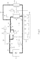
FIG. 1 is a schematic view of a fuel cell system for a vehicle according to an exemplary embodiment. -
FIG. 2 is a schematic view for explaining a second cooler and a flow rate adjuster in the fuel cell system for the vehicle ofFIG. 1 . -
FIG. 3 is a schematic view for explaining a first connection line and a second connection line in the fuel cell system for the vehicle ofFIG. 1 . - The invention is described more fully hereinafter with reference to the accompanying drawings, in which embodiments of the invention are shown. This invention may, however, be embodied in many different forms and should not be construed as limited to the embodiments set forth herein. Rather, these embodiments are provided so that this disclosure is thorough, and will fully convey the scope of the invention to those skilled in the art. Like reference numerals in the drawings denote like elements.
- Hereinafter, exemplary embodiments will be described in detail with reference to the accompanying drawings.
- However, the technical concepts of the present disclosure are not limited to some exemplary embodiments described herein but may be implemented in various different forms. One or more of the constituent elements in the exemplary embodiments may be selectively combined and substituted within the scope of the technical concepts of the present disclosure.
- In addition, unless otherwise specifically and explicitly defined and stated, the terms (including technical and scientific terms) used in the exemplary embodiments may be construed as the meaning which may be commonly understood by the person with ordinary skill in the art to which the present disclosure pertains. The meanings of the commonly used terms such as the terms defined in dictionaries may be interpreted in consideration of the contextual meanings of the related technology.
- In addition, the terms used in the exemplary embodiments are for explaining the exemplary embodiments, not for limiting the exemplary embodiments.
- Unless particularly stated otherwise in context of the following descriptions, a singular form may also include a plural form. The explanation "at least one (or one or more) of A, B, and C" described herein may include one or more of all combinations that can be made by combining A, B, and C.
- In addition, the terms such as first, second, A, B, (a), and (b) may be used to describe constituent elements of the exemplary embodiments.
- These terms are used only for the purpose of discriminating one constituent element from another constituent element, and the nature, the sequences, or the orders of the constituent elements are not limited by the terms.
- Further, when one constituent element is described as being 'connected', 'coupled', or 'attached' to another constituent element, one constituent element can be connected, coupled, or attached directly to another constituent element or connected, coupled, or attached to another constituent element through still another constituent element interposed therebetween.
- In addition, the explanation "one constituent element is formed or disposed above (on) or below (under) another constituent element" includes not only a case in which the two constituent elements are in direct contact with each other, but also a case in which one or more additional constituent elements are formed or disposed between the two constituent elements. In addition, the expression "up (above) or down (below)" may include a meaning of a downward direction as well as an upward direction based on one constituent element.
- Referring to
FIGS. 1 ,2 , and3 , a fuel cell system for a vehicle according to an exemplary embodiment includes afirst cooling line 110 configured to pass through afuel cell stack 10 in a vehicle and allow a first coolant to circulate therein, afirst cooler 60 connected to thefirst cooling line 110 and configured to cool the first coolant, and asecond cooler 80 connected to thefirst cooling line 110 and configured to cool the first coolant independently from thefirst cooler 60. - For example, in the exemplary embodiment, the
first cooling line 110 and asecond cooling line 120 may form a thermal management system (TMS) line in which the coolant (e.g., the first coolant and a second coolant) may flow while performing heat exchange. The coolant may be used as a cooling medium or a heating medium in the TMS line. - The
first cooling line 110 is configured to pass through thefuel cell stack 10, and the first coolant circulates along thefirst cooling line 110. - The
first cooling line 110 is configured to define a cooling loop for cooling (i.e., decreasing the temperature of) the first coolant or a heating loop for heating (i.e., increasing the temperature of) the first coolant depending on a state of the vehicle. As an example, thefirst cooling line 110 may be configured to define the heating loop in order to ensure/guarantee a cold start ability in an initial start state, and define the cooling loop in order to discharge heat generated in thefuel cell stack 10 to the outside while the vehicle travels. - For example, the
fuel cell stack 10 may have various structures capable of producing electricity by means of an oxidation-reduction reaction between fuel (e.g., hydrogen) and an oxidant (e.g., air). - As an example, the
fuel cell stack 10 includes: a membrane electrode assembly (MEA) having catalyst electrode layers, in which electrochemical reactions occur, at both sides of an electrolyte membrane through which hydrogen ions move; a gas diffusion layer (GDL) configured to uniformly distribute reactant gases and serve to transfer generated electrical energy; a gasket and a fastener configured to maintain leakproof and sealability for the reactant gases and the first coolant and maintain an appropriate fastening pressure; and a separator (e.g., bipolar plate) configured to move the reactant gases and the first coolant. - More specifically, in the
fuel cell stack 10, fuel (e.g., hydrogen) and an oxidant (e.g., air or oxygen) are supplied to an anode and a cathode of the membrane electrode assembly, respectively, through flow paths in the separator, such that the hydrogen as the fuel is supplied to the anode, and the air or oxygen as the oxidant is supplied to the cathode. - The hydrogen as the fuel supplied to the anode is decomposed into hydrogen ions (e.g., protons) and electrons by catalysts in the electrode layers provided at both sides of the electrolyte membrane. Only the hydrogen ions are selectively delivered to the cathode through the electrolyte membrane, and at the same time, the electrons are delivered to the cathode through the gas diffusion layer and the separator. For example, the electrolyte membrane may be a positive ion exchange membrane, and the gas diffusion layer and the separator may be conductors.
- At the cathode, the hydrogen ions supplied through the electrolyte membrane and the electrons delivered through the separator meet oxygen in the air supplied to the cathode by an air supply device to create a reaction of producing water. Due to the movement of the hydrogen ions, the electrons flow through external conductive wires, and an electric current is produced by the flow of the electrons.
- The
first cooler 60 for cooling the first coolant is provided in thefirst cooling line 110. For example, thefirst cooler 60 for cooling the first coolant is connected to thefirst cooling line 110 such that thefirst cooler 60 and thefirst cooling line 110 form the flowing path of the first coolant. - Various coolers capable of cooling the first coolant may be used as the
first cooler 60, and the exemplary embodiments are not restricted or limited by the type and the structure of thefirst cooler 60. - As an example, the
first cooler 60 may include afirst radiator 61 connected to thefirst cooling line 110 and configured to cool the first coolant. - The
first radiator 61 is connected to thefirst cooling line 110 in order to cool the first coolant, and the structure and the shape of thefirst radiator 61 may be variously changed in accordance with required conditions and design specifications. - Further, the
first radiator 61 is connected to afirst reservoir 64 configured to store the first coolant. - In addition, a
first pump 30 configured to force the first coolant to flow is provided in thefirst cooling line 110. For example, thefirst pump 30 is connected to thefirst cooling line 110 to form the flowing path of the first coolant. - Various pumps capable of pumping the first coolant may be used as the
first pump 30, and the exemplary embodiments are not restricted or limited by the type and the property of thefirst pump 30. - Referring to
FIGS. 1 and2 , thesecond cooler 80 is provided in thefirst cooling line 110 in order to cool the first coolant independently from thefirst cooler 60. - Various coolers capable of cooling the first coolant may be used as the
second cooler 80, and the exemplary embodiments are not restricted or limited by the type and the structure of thesecond cooler 80. - As an example, the
second cooler 80 includes afirst branch line 160 branching off from thefirst cooling line 110, and asecond radiator 81 provided in thefirst branch line 160. For example, thesecond radiator 81 is be connected in parallel to thefirst radiator 61 and configured to cool the first coolant independently from thefirst radiator 61. - More specifically, one end of the
first branch line 160 is connected to a first portion of thefirst cooling line 110 between an outlet of thefuel cell stack 10 and an inlet of thefirst radiator 61, and the other end of thefirst branch line 160 is connected to a second portion of thefirst cooling line 110 between an outlet of thefirst radiator 61 and an inlet of thefuel cell stack 10. - In particular, the
second radiator 81 is configured to be cooled by asecond cooling fan 82 that blows outside air. - As described above, in the exemplary embodiment, the first coolant introduced into the
fuel cell stack 10 is cooled individually by thefirst cooler 60 and thesecond cooler 80, such that it is possible to obtain an advantageous effect of ensuring a high output from thefuel cell stack 10 and improving safety and reliability. - In particular, according to the exemplary embodiment, it is possible to lower the temperature of the first coolant by using the
first cooler 60 and thesecond cooler 80 while a vehicle (e.g., a construction machine), which cannot use the vehicle-induced wind, is stationary, thereby obtaining an advantageous effect of ensuring a high-output operation of thefuel cell stack 10 and improving safety and durability. - In particular, a first on-off
valve 162 configured to selectively open or close thefirst branch line 160 may be provided in thefirst branch line 160. - For example, the first on-off
valve 162 is provided between the other end of the first branch line 160 (e.g., the second portion of thefirst cooling line 110 between the outlet of thefirst radiator 61 and the inlet of the fuel cell stack 10) and an outlet of thesecond radiator 81 in order to selectively open or close thefirst branch line 160. - Various valves capable of selectively opening or closing the
first branch line 160 may be used as the first on-offvalve 162, and the exemplary embodiments are not restricted or limited by the type and the structure of the first on-offvalve 162. - As an example, a typical two-way valve may be used as the first on-off
valve 162. - In a state in which the first on-off
valve 162 opens thefirst branch line 160, the first coolant may be cooled while passing through both thefirst radiator 61 and thesecond radiator 81. In contrast, in a state in which the first on-offvalve 162 closes thefirst branch line 160, the first coolant passes only through thefirst radiator 61 without passing through thesecond radiator 81, and as a result, the first coolant may be cooled only by thefirst radiator 61. - For example, in a situation in which a large amount of heat needs to be radiated/discharged from the fuel cell stack 10 (e.g., during a high-output operation of the
fuel cell stack 10 while the vehicle is stationary), the first on-offvalve 162 is opened, and thus the first coolant may be cooled by both thefirst radiator 61 and thesecond radiator 81, such that the first coolant may be cooled more quickly and effectively. In contrast, during a low-output operation of thefuel cell stack 10, the first on-offvalve 162 is closed, and thus the first coolant may be cooled only by thefirst radiator 61. - The fuel cell system for a vehicle according to the exemplary embodiment may include the
first pump 30 provided in thefirst cooling line 110 and configured to pump the first coolant, and aflow rate adjuster 170 provided in thefirst cooling line 110 and configured to adjust a flow rate of the first coolant to be introduced into thefuel cell stack 10 independently from thefirst pump 30. For example, theflow rate adjuster 170 is connected in parallel to thefirst pump 30. - This is to prevent the efficiency in cooling the
fuel cell stack 10 from being degraded due to an insufficient flow rate of the first coolant. - For example, in a case in which a flow rate of the first coolant is lower than a target flow rate (a predetermined flow rate) during the high-output operation of the
fuel cell stack 10, there is a problem in that the efficiency in cooling thefuel cell stack 10 is degraded even though a temperature of the first coolant is within an appropriate temperature range. - However, according to the exemplary embodiments, since the
flow rate adjuster 170 configured to adjust a flow rate of the first coolant is provided in thefirst cooling line 110, it is possible to obtain an advantageous effect of minimizing a decrease in flow rate of the first coolant to be introduced into thefuel cell stack 10. - The
flow rate adjuster 170 may have various structures capable of adjusting a flow rate of the first coolant, and the exemplary embodiments are not restricted or limited by the structure of theflow rate adjuster 170. - As an example, the
flow rate adjuster 170 may include asecond branch line 172 branching off from thefirst cooling line 110, and asecond pump 174 provided in thesecond branch line 172. For example, thesecond pump 174 is connected in parallel to thefirst pump 30 through thesecond branch line 172 and configured to pump the first coolant. - In particular, one end of the
second branch line 172 is connected to a portion of thefirst cooling line 110 between the outlet of thefirst radiator 61 and thefirst pump 30, and the other end of thesecond branch line 172 is connected to a portion of thefirst cooling line 110 between thefirst pump 30 and the inlet of thefuel cell stack 10. - The
second pump 174 is configured to force the first coolant to flow through thesecond branch line 172. - Various pumps capable of pumping the first coolant may be used as the
second pump 174, and the exemplary embodiments are not restricted or limited by the type and the property of thesecond pump 174. - In particular, a second on-off
valve 176 configured to selectively open or close thesecond branch line 172 may be provided in thesecond branch line 172. - For example, the second on-off
valve 176 is provided between the other end of thesecond branch line 172 and thesecond pump 174 in order to selectively open or close thesecond branch line 172. - Various valves capable of selectively opening or closing the
second branch line 172 may be used as the second on-offvalve 176, and the exemplary embodiments are not restricted or limited by the type and the structure of the second on-offvalve 176. - As an example, a typical two-way valve may be used as the second on-off
valve 176. - In a state in which the second on-off
valve 176 opens thesecond branch line 172, the first coolant may be pumped by both thefirst pump 30 and thesecond pump 174. In contrast, when the second on-offvalve 176 closes thesecond branch line 172, the first coolant may be pumped only by thefirst pump 30, and the first coolant pumped by thefirst pump 30 may be prevented from being introduced into thesecond pump 174. - For example, in a situation in which a large amount of heat needs to be radiated/discharged from the fuel cell stack 10 (e.g., during a high-output operation of the
fuel cell stack 10 while the vehicle is stationary), the second on-offvalve 176 is opened, and thus the first coolant may be pumped by both thefirst pump 30 and thesecond pump 174, such that a sufficient flow rate of the first coolant may be ensured/guaranteed. In contrast, during a low-output operation of thefuel cell stack 10, the second on-offvalve 176 is closed, and thus the first coolant may be pumped only by thefirst pump 30. - Referring to
FIGS. 1 and3 , the fuel cell system according to the exemplary embodiment may include afirst connection line 130, and thefirst connection line 130 may define a heating loop (e.g., a heating circulation route) for heating the first coolant in cooperation with thefirst cooling line 110. - More specifically, one end of the
first connection line 130 is connected to thefirst cooling line 110 at a first point positioned between an outlet of thefirst pump 30 and thefuel cell stack 10, and the other end of thefirst connection line 130 is connected to thefirst cooling line 110 at a second point positioned between an inlet of thefirst pump 30 and thefuel cell stack 10. - In this case, the inlet of the
first pump 30 is defined as an inlet through which the first coolant is introduced into thefirst pump 30. In addition, the outlet of thefirst pump 30 is defined as an outlet through which the first coolant having passed through thefirst pump 30 is discharged. - Further, the
first cooling line 110 between the outlet of thefirst pump 30 and thefuel cell stack 10 is defined as a section in which the first coolant discharged from thefirst pump 30 flows to a first coolant inlet port of thefuel cell stack 10. In addition, thefirst cooling line 110 between the inlet of thefirst pump 30 and thefuel cell stack 10 is defined as a section in which the first coolant discharged from a coolant discharge port of thefuel cell stack 10 flows to the inlet of thefirst pump 30. - According to the exemplary embodiment, a
heater 50 may be connected to thefirst connection line 130, and the first coolant flowing along thefirst connection line 130 may be heated while passing through theheater 50. - In addition, a
first valve 20 configured to switch a flow path of the first coolant to theheater 50 or thefuel cell stack 10 is provided in thefirst cooling line 110. - As an example, the
first valve 20 is provided in thefirst cooling line 110 so as to be positioned at the first point, and one end of thefirst connection line 130 is connected to thefirst valve 20. - Various valves capable of selectively switching the flow path of the first coolant to the
heater 50 or thefuel cell stack 10 may be used as thefirst valve 20. - As an example, a typical three-way valve may be used as the
first valve 20. More specifically, thefirst valve 20 includes afirst port 21 connected to thefirst cooling line 110 so that the first coolant pumped by thefirst pump 30 is introduced into thefirst valve 20, asecond port 22 connected to thefirst cooling line 110 so that the first coolant passing through thefirst valve 20 is introduced into thefuel cell stack 10, and athird port 23 connected to one end of thefirst connection line 130. - It is possible to selectively switch the flow path of the first coolant to the
heater 50 or thefuel cell stack 10 by opening and closing thesecond port 22 and thethird port 23 of thefirst valve 20. For example, when thesecond port 22 is opened and thethird port 23 is closed, the first coolant passing through thefirst valve 20 is introduced into thefuel cell stack 10. On the contrary, when thethird port 23 is opened and thesecond port 22 is closed, the first coolant passing through thefirst valve 20 is introduced into theheater 50 through thefirst connection line 130. - The fuel cell system according to the exemplary embodiment may include a
second connection line 150 connected to thefirst cooling line 110 and configured to define a cooling/heating loop for cooling and heating an air conditioner (e.g., HVAC) 90 in cooperation with thefirst cooling line 110. - As an example, the
second connection line 150 may define a loop for heating a heater of theair conditioner 90. - More specifically, the
second connection line 150 is connected to thefirst cooling line 110 between the first point (e.g., at which one end of the first connection line 13 0 is connected to the first cooling line 110) and the outlet of thefuel cell stack 10, and thesecond connection line 150 is configured to allow a part of the first coolant to circulate therein. - In this case, the
first cooling line 110 between the first point and the outlet of thefuel cell stack 10 is defined as a section in which the first coolant discharged from the coolant discharge port of thefuel cell stack 10 flows before passing through the first point. - As an example, one end of the
second connection line 150 is connected to thefirst cooling line 110 between the first point and the inlet of thefuel cell stack 10, and the other end of thesecond connection line 150 is connected to thefirst cooling line 110 between thefirst pump 30 and the second point. - In addition, the
second connection line 150 may be provided with anion filter 95 configured to filter out ions contained in the first coolant that has passed through theair conditioner 90. - For example, when electrical conductivity of the first coolant is increased due to corrosion, exudation, or the like of the system, electricity flows to the first coolant, which causes a problem in that the
fuel cell stack 10 is short-circuited or electric current flows toward the first coolant. Therefore, low electrical conductivity of the first coolant needs to be maintained. - The
ion filter 95 is configured to remove the ions contained in the first coolant in order to reduce the electrical conductivity of the first coolant to a predetermined level or lower. - As described above, according to the exemplary embodiments, the first coolant also circulates along the
second connection line 150 while circulating (e.g., along the heating loop) via theheater 50 in thefirst connection line 130 during the cold start in which the supply of the first coolant to thefuel cell stack 10 is cut off (e.g., the second port of the first valve is closed), and as a result, theion filter 95 provided in thesecond connection line 150 may filter out (or remove) the ions contained in the first coolant even during the cold start. Therefore, it is possible to obtain an advantageous effect of reducing the electrical conductivity of the first coolant, which is introduced into thefuel cell stack 10 immediately after the cold start, to a predetermined level or lower. - In addition, in the exemplary embodiment, the
first cooling line 110 is configured to pass through thefirst radiator 61 between thefirst pump 30 and the outlet of thefuel cell stack 10, and the fuel cell system may include athird connection line 140 having one end connected to thefirst cooling line 110 at a front side of thefirst radiator 61, and the other end connected to thefirst cooling line 110 at a rear side of thefirst radiator 61. - Referring to
FIGS. 1 and3 , thethird connection line 140 is connected to thefirst cooling line 110 and provided to define a cooling loop for cooling the first coolant in cooperation with thefirst cooling line 110. As an example, one end of thethird connection line 140 may be connected to thefirst cooling line 110 between thefirst pump 30 and thefirst radiator 61, and the other end of thethird connection line 140 may be connected to thefirst cooling line 110 between the coolant discharge port of thefuel cell stack 10 and thefirst radiator 61. - In addition, a
second valve 40 configured to switch a flow path of the first coolant to thefirst radiator 61 or thefuel cell stack 10 is provided in thefirst cooling line 110. - As an example, the
second valve 40 is provided in thefirst cooling line 110 so as to be positioned between thefirst pump 30 and thefirst radiator 61, and thesecond valve 40 is connected to one end of thethird connection line 140 and an outlet end (e.g., the other end) of thesecond connection line 150. - Various valves capable of selectively switching the flow path of the first coolant to the
first radiator 61 or thefuel cell stack 10 may be used as thesecond valve 40. - As an example, a typical four-way valve may be used as the
second valve 40. More specifically, thesecond valve 40 includes afirst port 41 connected to thethird connection line 140, asecond port 42 connected to thefirst cooling line 110, athird port 43 connected to the other end of thesecond connection line 150, and afourth port 44 connected to thefirst cooling line 110. For example, the first coolant passing through thefirst radiator 61 is introduced into thesecond valve 40 through thesecond port 42. The first coolant passing through thesecond valve 40 is introduced into thefirst pump 30 through thefourth port 44. - It is possible to selectively switch the flow path of the first coolant to the
first radiator 61 or thefuel cell stack 10 by opening and closing thefirst port 41 and thesecond port 42 of thesecond valve 40. For example, when thefirst port 41 is opened and thesecond port 42 is closed, the first coolant is introduced into thefuel cell stack 10 without passing through thefirst radiator 61. On the contrary, when thesecond port 42 is opened and thefirst port 41 is closed, the first coolant passes through thefirst radiator 61 and then enters thefuel cell stack 10. - Meanwhile, the fuel cell system according to the exemplary embodiment may include a
first temperature sensor 112 configured to measure the temperature of the first coolant between thefuel cell stack 10 and the first point (e.g., the first valve), asecond temperature sensor 114 configured to measure the temperature of the first coolant between the other end of thefirst connection line 130 and thefirst pump 30, and athird temperature sensor 116 configured to measure the temperature of the first coolant in theheater 50. An inflow rate of the first coolant to be introduced into thefuel cell stack 10 may be controlled based on the temperatures measured by thefirst temperature sensor 112, thesecond temperature sensor 114, and thethird temperature sensor 116. - As an example, when a measured temperature of the first coolant circulating along the
first cooling line 110 is lower than a predetermined target temperature, an inflow rate of the first coolant may be controlled to be lower than a predetermined flow rate. As described above, since the inflow rate of the first coolant to be introduced into thefuel cell stack 10 is controlled to be lower than the predetermined flow rate when the measured temperature of the first coolant is lower than the predetermined target temperature, it is possible to obtain an advantageous effect of minimizing a thermal shock and a degradation in performance caused by a deviation in temperature of the first coolant (e.g., the difference between the temperature of the first coolant stagnating in thefuel cell stack 10 and the temperature of the first coolant to be introduced into the fuel cell stack 10). - The fuel cell system according to the exemplary embodiment may include the
second cooling line 120 configured to pass through powerelectronic parts 200 of the vehicle, and the second coolant may circulate along thesecond cooling line 120. - In this case, the power
electronic parts 200 of the vehicle may be understood as components that use electric power of the vehicle as an energy source, and the exemplary embodiments are not restricted or limited by the type and the number of powerelectronic parts 200 of the vehicle. - As an example, the power
electronic part 200 may include at least one of a bi-directional high-voltage DC-DC converter (BHDC) 210 provided between thefuel cell stack 10 and a high-voltage battery of the vehicle, a blower pump control unit (BPCU) 220 configured to control a blower configured to supply outside air for operating thefuel cell stack 10, a low-voltage DC-DC converter (LDC) 230 configured to convert a high direct-current voltage (which is supplied from the high-voltage battery) into a low direct-current voltage, an air compressor (ACP) 240 configured to compress air to be supplied to thefuel cell stack 10, and anair cooler 250. - A third pump configured to force the second coolant to flow is provided in the
second cooling line 120. - Various pumps capable of pumping the second coolant may be used as the third pump, and the exemplary embodiments are not restricted or limited by the type and the property of the third pump.
- In addition, a
third radiator 71 configured to cool the second coolant may be provided in thesecond cooling line 120. - The
third radiator 71 may have various structures capable of cooling the second coolant, and the exemplary embodiments are not restricted or limited by the type and the structure of thethird radiator 71. - Further, the
third radiator 71 may be connected to asecond reservoir 74 configured to store the second coolant. - In particular, the
first radiator 61 and thethird radiator 71 are configured to be simultaneously cooled by the same first coolingfan 62. As an example, thefirst radiator 61 and thethird radiator 71 are disposed in parallel, and thefirst cooling fan 62 is provided to blow outside air to thefirst radiator 61 and thethird radiator 71. - As described above, since the
first radiator 61 and thethird radiator 71 are simultaneously cooled by the same first coolingfan 62, it is possible to obtain an advantageous effect of simplifying the structure, improving a degree of design freedom and spatial utilization, and minimizing consumption of electric power required to cool thefirst radiator 61 and thethird radiator 71. - According to the exemplary embodiment as described above, it is possible to obtain an advantageous effect of ensuring a high output from the fuel cell stack and improving safety and reliability.
- In particular, according to the exemplary embodiment, it is possible to obtain an advantageous effect of effectively cooling the fuel cell stack and improving operating performance and operational efficiency of the fuel cell stack in the situation in which a high output is required from the fuel cell stack while the vehicle is stationary.
- In addition, according to the exemplary embodiment, it is possible to obtain an advantageous effect of minimizing a decrease in flow rate of the coolant to be introduced into the fuel cell stack and preventing a degradation in cooling performance of the fuel cell stack.
- While the exemplary embodiments have been described above, the exemplary embodiments are just illustrative and not intended to limit the present disclosure. It can be appreciated by those skilled in the art that various modifications and alterations, which are not described above, may be made to the illustrated exemplary embodiment without departing from the intrinsic features of the illustrated exemplary embodiments. For example, the respective constituent elements specifically described in the exemplary embodiments may be modified and then carried out. Further, it should be interpreted that the differences related to the modifications and alterations are included in the scope of the exemplary embodiments defined by the appended claims.
-
- 10:
- Fuel cell stack
- 20:
- First valve
- 30:
- First pump
- 40:
- Second valve
- 50:
- Heater
- 60:
- First cooler
- 61:
- First radiator
- 62:
- First cooling fan
- 64:
- First reservoir
- 71:
- Third radiator
- 74:
- Second reservoir
- 80:
- Second cooler
- 81:
- Second radiator
- 82:
- Second cooling fan
- 90:
- Air conditioner
- 95:
- Ion filter
- 110:
- First cooling line
- 120:
- Second cooling line
- 130:
- First connection line
- 140:
- Third connection line
- 150:
- Second connection line
- 160:
- First branch line
- 162:
- First on-off valve
- 170:
- Flow rate adjuster
- 172:
- Second branch line
- 174:
- Second pump
- 176:
- Second on-off valve
- 112:
- First temperature sensor
- 114:
- Second temperature sensor
- 116:
- Third temperature sensor
- 200:
- Power electronic part
Claims (13)
- A fuel cell system for a vehicle, the fuel cell system comprising:a first cooling line configured to pass through a fuel cell stack in a vehicle and to circulate a first coolant therein;a first cooler provided in the first cooling line and configured to cool the first coolant; anda second cooler provided in the first cooling line and configured to cool the first coolant independently from the first cooler.
- The fuel cell system of claim 1, wherein the first cooler comprises a first radiator connected to the first cooling line and configured to cool the first coolant, and the second cooler comprises a first branch line which branches off from the first cooling line, and a second radiator connected to the first branch line, the second radiator connected in parallel to the first radiator through the first branch line and configured to cool the first coolant.
- The fuel cell system of claim 2, wherein a first end of the first branch line is connected to a first portion of the first cooling line between an outlet of the fuel cell stack and an inlet of the first radiator, and a second end of the first branch line is connected to a second portion of the first cooling line between an outlet of the first radiator and an inlet of the fuel cell stack.
- The fuel cell system of claim 3, further comprising:
a first on-off valve configured to selectively open or close the first branch line and disposed between the second end of the first branch line and an outlet of the second radiator. - The fuel cell system of claim 2, further comprising:a first pump provided in the first cooling line and configured to pump the first coolant; anda flow rate adjuster provided in the first cooling line and configured to adjust a flow rate of the first coolant to be introduced into the fuel cell stack independently from the first pump.
- The fuel cell system of claim 5, wherein the flow rate adjuster comprises:a second branch line branching off from the first cooling line; anda second pump provided in the second branch line, the second pump connected in parallel to the first pump through the second branch line and configured to pump the first coolant.
- The fuel cell system of claim 6, wherein a first end of the second branch line is connected to a first portion of the first cooling line between an outlet of the first radiator and the first pump, and a second end of the second branch line is connected to a second portion of the first cooling line between the first pump and an inlet of the fuel cell stack.
- The fuel cell system of claim 7, further comprising:
a second on-off valve configured to selectively open or close the second branch line and disposed between the second end of the second branch line and the second pump. - The fuel cell system of claim 2, further comprising:a second cooling line configured to pass through a power electronic circuit of the vehicle and configured to allow a second coolant to circulate therein; anda third radiator provided in the second cooling line and configured to cool the second coolant.
- The fuel cell system of claim 9, wherein the power electronic circuit comprises at least one of a bi-directional high-voltage DC-DC converter (BHDC) provided between the fuel cell stack and a high-voltage battery of the vehicle, a blower pump controller (BPCU) configured to control a blower configured to supply outside air for operating the fuel cell stack, a low-voltage DC-DC converter (LDC) configured to convert a high direct-current voltage, which is supplied from the high-voltage battery, into a low direct-current voltage, an air compressor (ACP) configured to compress air to be supplied to the fuel cell stack, and an air cooler.
- The fuel cell system of claim 9, wherein the first radiator and the third radiator are disposed in parallel, and the fuel cell system further comprises a first cooling fan configured to blow outside air to the first radiator and the third radiator.
- The fuel cell system of claim 2, further comprising:
a second cooling fan configured to blow outside air to the second radiator. - The fuel cell system of claim 2, further comprising:a first connection line having a first end connected to the first cooling line between an outlet of the first radiator and an inlet of the fuel cell stack, and a second end connected to the first cooling line between an outlet of the fuel cell stack and an inlet of the first radiator;a heater provided in the first connection line and configured to heat the first coolant flowing through the first connection line; anda second connection line configured to pass through an air conditioner in the vehicle, connected to the first cooling line between the outlet of the first radiator and the inlet of the fuel cell stack, and configured to circulate the first coolant therein.
Applications Claiming Priority (1)
| Application Number | Priority Date | Filing Date | Title |
|---|---|---|---|
| KR1020200073074A KR102387889B1 (en) | 2020-06-16 | 2020-06-16 | Fuel cell system for vehicle |
Publications (1)
| Publication Number | Publication Date |
|---|---|
| EP3926722A1 true EP3926722A1 (en) | 2021-12-22 |
Family
ID=72603433
Family Applications (1)
| Application Number | Title | Priority Date | Filing Date |
|---|---|---|---|
| EP20198274.1A Pending EP3926722A1 (en) | 2020-06-16 | 2020-09-25 | Fuel cell system for vehicle |
Country Status (5)
| Country | Link |
|---|---|
| US (1) | US11450872B2 (en) |
| EP (1) | EP3926722A1 (en) |
| JP (1) | JP7610776B2 (en) |
| KR (1) | KR102387889B1 (en) |
| CN (1) | CN213242608U (en) |
Families Citing this family (7)
| Publication number | Priority date | Publication date | Assignee | Title |
|---|---|---|---|---|
| JP2022157510A (en) * | 2021-03-31 | 2022-10-14 | 本田技研工業株式会社 | Method for operating fuel cell system |
| KR102550728B1 (en) * | 2021-07-01 | 2023-07-04 | 현대모비스 주식회사 | Method for dealing with faults in in fuel cell system |
| KR102585300B1 (en) * | 2021-11-18 | 2023-10-05 | 현대모비스 주식회사 | Fuel cell system and contorl method using the same |
| CN114566682A (en) * | 2022-03-01 | 2022-05-31 | 苏州中车氢能动力技术有限公司 | Dipping machine system for low-temperature characteristic test of fuel cell system and test system |
| JP7531538B2 (en) * | 2022-03-29 | 2024-08-09 | 本田技研工業株式会社 | Fuel Cell Systems |
| US12451499B2 (en) | 2022-04-29 | 2025-10-21 | Toyota Motor Engineering & Manufacturing North America, Inc | Auxiliary thermal regulation of fuel cell stack |
| US12439569B2 (en) * | 2022-06-13 | 2025-10-07 | Cooper-Standard Automotive, Inc. | Shift pump flow scheme |
Citations (8)
| Publication number | Priority date | Publication date | Assignee | Title |
|---|---|---|---|---|
| US5537956A (en) * | 1993-08-13 | 1996-07-23 | Daimler-Benz Ag | Coolant circuit |
| JP2003168462A (en) * | 2001-11-30 | 2003-06-13 | Denso Corp | Fuel cell cooling system and electric vehicle |
| JP2007038950A (en) * | 2005-08-05 | 2007-02-15 | Suzuki Motor Corp | Air conditioning system for vehicles equipped with fuel cells |
| DE102010014752A1 (en) * | 2010-04-13 | 2010-11-11 | Daimler Ag | Cooling arrangement for e.g. hybrid electric vehicle, has two exhaust gas releasing devices connected in series or parallel to cooling circuit, and coupling elements for connecting electric energy storage to cooling circuit |
| US20120129066A1 (en) * | 2008-12-22 | 2012-05-24 | Renault S.A.S. | Device and method for cooling a thermal member in an automobile |
| DE102015003028A1 (en) * | 2015-03-10 | 2016-09-15 | Daimler Ag | Cooling arrangement for cooling a fuel cell |
| DE102016110964A1 (en) * | 2016-06-15 | 2017-12-21 | Volkswagen Ag | Fuel cell cooling system with two cooling circuits and method for switching off a fuel cell |
| CN210554237U (en) * | 2019-09-16 | 2020-05-19 | 江苏重塑能源科技有限公司 | Fuel cell system and automobile |
Family Cites Families (10)
| Publication number | Priority date | Publication date | Assignee | Title |
|---|---|---|---|---|
| JP2000315513A (en) * | 1999-05-06 | 2000-11-14 | Nissan Motor Co Ltd | Radiator system for fuel cell vehicle |
| JP4296144B2 (en) | 2004-09-29 | 2009-07-15 | 本田技研工業株式会社 | Fuel cell motorcycle |
| JP5321910B2 (en) | 2009-09-24 | 2013-10-23 | スズキ株式会社 | Hybrid vehicle cooling system |
| JP6239913B2 (en) * | 2013-09-24 | 2017-11-29 | トヨタ自動車株式会社 | Temperature control device and temperature control method |
| JP6455408B2 (en) | 2015-11-26 | 2019-01-23 | 株式会社デンソー | Control device for fuel cell system |
| JP2017199611A (en) * | 2016-04-28 | 2017-11-02 | 株式会社デンソー | On-vehicle fuel cell system |
| KR102529902B1 (en) * | 2016-12-12 | 2023-05-08 | 현대자동차주식회사 | Fuel cell system |
| JP6897489B2 (en) * | 2017-10-23 | 2021-06-30 | トヨタ自動車株式会社 | Fuel cell vehicle |
| KR102496804B1 (en) * | 2017-12-01 | 2023-02-06 | 현대자동차 주식회사 | Thermal management system of fuel cell vehicle |
| JP7043946B2 (en) * | 2018-04-06 | 2022-03-30 | トヨタ自動車株式会社 | Fuel cell system |
-
2020
- 2020-06-16 KR KR1020200073074A patent/KR102387889B1/en active Active
- 2020-09-21 US US17/027,514 patent/US11450872B2/en active Active
- 2020-09-25 EP EP20198274.1A patent/EP3926722A1/en active Pending
- 2020-09-30 JP JP2020165154A patent/JP7610776B2/en active Active
- 2020-10-15 CN CN202022295834.3U patent/CN213242608U/en active Active
Patent Citations (8)
| Publication number | Priority date | Publication date | Assignee | Title |
|---|---|---|---|---|
| US5537956A (en) * | 1993-08-13 | 1996-07-23 | Daimler-Benz Ag | Coolant circuit |
| JP2003168462A (en) * | 2001-11-30 | 2003-06-13 | Denso Corp | Fuel cell cooling system and electric vehicle |
| JP2007038950A (en) * | 2005-08-05 | 2007-02-15 | Suzuki Motor Corp | Air conditioning system for vehicles equipped with fuel cells |
| US20120129066A1 (en) * | 2008-12-22 | 2012-05-24 | Renault S.A.S. | Device and method for cooling a thermal member in an automobile |
| DE102010014752A1 (en) * | 2010-04-13 | 2010-11-11 | Daimler Ag | Cooling arrangement for e.g. hybrid electric vehicle, has two exhaust gas releasing devices connected in series or parallel to cooling circuit, and coupling elements for connecting electric energy storage to cooling circuit |
| DE102015003028A1 (en) * | 2015-03-10 | 2016-09-15 | Daimler Ag | Cooling arrangement for cooling a fuel cell |
| DE102016110964A1 (en) * | 2016-06-15 | 2017-12-21 | Volkswagen Ag | Fuel cell cooling system with two cooling circuits and method for switching off a fuel cell |
| CN210554237U (en) * | 2019-09-16 | 2020-05-19 | 江苏重塑能源科技有限公司 | Fuel cell system and automobile |
Also Published As
| Publication number | Publication date |
|---|---|
| US20210391588A1 (en) | 2021-12-16 |
| US11450872B2 (en) | 2022-09-20 |
| CN213242608U (en) | 2021-05-18 |
| KR20210155619A (en) | 2021-12-23 |
| JP2021195113A (en) | 2021-12-27 |
| JP7610776B2 (en) | 2025-01-09 |
| KR102387889B1 (en) | 2022-04-18 |
Similar Documents
| Publication | Publication Date | Title |
|---|---|---|
| US11450872B2 (en) | Fuel cell system for vehicle | |
| US11296335B2 (en) | Fuel cell system and method of operating same | |
| US8883362B2 (en) | Fuel cell system | |
| US11833927B2 (en) | Thermal management system for fuel cell vehicle | |
| US10535887B2 (en) | Fuel cell system | |
| US12095123B2 (en) | Fuel cell system for vehicle | |
| KR20230005549A (en) | Method for dealing with faults in in fuel cell system | |
| KR102607329B1 (en) | Fuel cell system and heater control method thereof | |
| US7919209B2 (en) | System stability and performance improvement with anode heat exchanger plumbing and re-circulation rate | |
| KR102962113B1 (en) | Fuel cell system and emergency driving control method thereof | |
| KR20170007056A (en) | Flux control apparatus of fuel cell vehicle cooling system and Control method thereof | |
| US20240222665A1 (en) | System and method for thermal management of electric parts | |
| US11705559B2 (en) | Fuel cell system | |
| KR20250130122A (en) | Fuel cell system and overcooling control method thereof | |
| KR20230016906A (en) | Fuel cell system and thermal management control method thereof | |
| KR20240064210A (en) | Fuel cell system | |
| KR20240035167A (en) | Fuel cell system and thermal management method thereof |
Legal Events
| Date | Code | Title | Description |
|---|---|---|---|
| PUAI | Public reference made under article 153(3) epc to a published international application that has entered the european phase |
Free format text: ORIGINAL CODE: 0009012 |
|
| STAA | Information on the status of an ep patent application or granted ep patent |
Free format text: STATUS: REQUEST FOR EXAMINATION WAS MADE |
|
| 17P | Request for examination filed |
Effective date: 20201007 |
|
| AK | Designated contracting states |
Kind code of ref document: A1 Designated state(s): AL AT BE BG CH CY CZ DE DK EE ES FI FR GB GR HR HU IE IS IT LI LT LU LV MC MK MT NL NO PL PT RO RS SE SI SK SM TR |
|
| B565 | Issuance of search results under rule 164(2) epc |
Effective date: 20210315 |
|
| RBV | Designated contracting states (corrected) |
Designated state(s): AL AT BE BG CH CY CZ DE DK EE ES FI FR GB GR HR HU IE IS IT LI LT LU LV MC MK MT NL NO PL PT RO RS SE SI SK SM TR |
|
| RAP1 | Party data changed (applicant data changed or rights of an application transferred) |
Owner name: KIA CORPORATION Owner name: HYUNDAI MOTOR COMPANY |
|
| RAP3 | Party data changed (applicant data changed or rights of an application transferred) |
Owner name: KIA CORPORATION Owner name: HYUNDAI MOTOR COMPANY |
|
| P01 | Opt-out of the competence of the unified patent court (upc) registered |
Free format text: CASE NUMBER: APP_3823/2025 Effective date: 20250123 |
|
| STAA | Information on the status of an ep patent application or granted ep patent |
Free format text: STATUS: EXAMINATION IS IN PROGRESS |
|
| 17Q | First examination report despatched |
Effective date: 20260203 |