EP3926653A1 - Contact bounce reduction system - Google Patents
Contact bounce reduction system Download PDFInfo
- Publication number
- EP3926653A1 EP3926653A1 EP20179976.4A EP20179976A EP3926653A1 EP 3926653 A1 EP3926653 A1 EP 3926653A1 EP 20179976 A EP20179976 A EP 20179976A EP 3926653 A1 EP3926653 A1 EP 3926653A1
- Authority
- EP
- European Patent Office
- Prior art keywords
- ball
- piston
- resilient member
- contact
- reduction system
- Prior art date
- Legal status (The legal status is an assumption and is not a legal conclusion. Google has not performed a legal analysis and makes no representation as to the accuracy of the status listed.)
- Granted
Links
Images


Classifications
-
- F—MECHANICAL ENGINEERING; LIGHTING; HEATING; WEAPONS; BLASTING
- F16—ENGINEERING ELEMENTS AND UNITS; GENERAL MEASURES FOR PRODUCING AND MAINTAINING EFFECTIVE FUNCTIONING OF MACHINES OR INSTALLATIONS; THERMAL INSULATION IN GENERAL
- F16F—SPRINGS; SHOCK-ABSORBERS; MEANS FOR DAMPING VIBRATION
- F16F15/00—Suppression of vibrations in systems; Means or arrangements for avoiding or reducing out-of-balance forces, e.g. due to motion
- F16F15/02—Suppression of vibrations of non-rotating, e.g. reciprocating systems; Suppression of vibrations of rotating systems by use of members not moving with the rotating systems
- F16F15/04—Suppression of vibrations of non-rotating, e.g. reciprocating systems; Suppression of vibrations of rotating systems by use of members not moving with the rotating systems using elastic means
- F16F15/06—Suppression of vibrations of non-rotating, e.g. reciprocating systems; Suppression of vibrations of rotating systems by use of members not moving with the rotating systems using elastic means with metal springs
- F16F15/067—Suppression of vibrations of non-rotating, e.g. reciprocating systems; Suppression of vibrations of rotating systems by use of members not moving with the rotating systems using elastic means with metal springs using only wound springs
-
- H—ELECTRICITY
- H01—ELECTRIC ELEMENTS
- H01H—ELECTRIC SWITCHES; RELAYS; SELECTORS; EMERGENCY PROTECTIVE DEVICES
- H01H1/00—Contacts
- H01H1/12—Contacts characterised by the manner in which co-operating contacts engage
- H01H1/14—Contacts characterised by the manner in which co-operating contacts engage by abutting
- H01H1/24—Contacts characterised by the manner in which co-operating contacts engage by abutting with resilient mounting
- H01H1/30—Contacts characterised by the manner in which co-operating contacts engage by abutting with resilient mounting within supporting guides
-
- H—ELECTRICITY
- H01—ELECTRIC ELEMENTS
- H01H—ELECTRIC SWITCHES; RELAYS; SELECTORS; EMERGENCY PROTECTIVE DEVICES
- H01H1/00—Contacts
- H01H1/50—Means for increasing contact pressure, preventing vibration of contacts, holding contacts together after engagement, or biasing contacts to the open position
-
- H—ELECTRICITY
- H01—ELECTRIC ELEMENTS
- H01H—ELECTRIC SWITCHES; RELAYS; SELECTORS; EMERGENCY PROTECTIVE DEVICES
- H01H1/00—Contacts
- H01H1/50—Means for increasing contact pressure, preventing vibration of contacts, holding contacts together after engagement, or biasing contacts to the open position
- H01H1/502—Means for increasing contact pressure, preventing vibration of contacts, holding contacts together after engagement, or biasing contacts to the open position the action of the contact pressure spring becoming active only after engagement of the contacts
-
- H—ELECTRICITY
- H01—ELECTRIC ELEMENTS
- H01H—ELECTRIC SWITCHES; RELAYS; SELECTORS; EMERGENCY PROTECTIVE DEVICES
- H01H50/00—Details of electromagnetic relays
- H01H50/54—Contact arrangements
- H01H50/56—Contact spring sets
- H01H50/58—Driving arrangements structurally associated therewith; Mounting of driving arrangements on armature
-
- H—ELECTRICITY
- H01—ELECTRIC ELEMENTS
- H01H—ELECTRIC SWITCHES; RELAYS; SELECTORS; EMERGENCY PROTECTIVE DEVICES
- H01H1/00—Contacts
- H01H1/12—Contacts characterised by the manner in which co-operating contacts engage
- H01H1/14—Contacts characterised by the manner in which co-operating contacts engage by abutting
- H01H1/24—Contacts characterised by the manner in which co-operating contacts engage by abutting with resilient mounting
-
- H—ELECTRICITY
- H01—ELECTRIC ELEMENTS
- H01H—ELECTRIC SWITCHES; RELAYS; SELECTORS; EMERGENCY PROTECTIVE DEVICES
- H01H2201/00—Contacts
- H01H2201/002—Contacts bounceless
-
- H—ELECTRICITY
- H01—ELECTRIC ELEMENTS
- H01H—ELECTRIC SWITCHES; RELAYS; SELECTORS; EMERGENCY PROTECTIVE DEVICES
- H01H50/00—Details of electromagnetic relays
- H01H50/54—Contact arrangements
-
- H—ELECTRICITY
- H01—ELECTRIC ELEMENTS
- H01H—ELECTRIC SWITCHES; RELAYS; SELECTORS; EMERGENCY PROTECTIVE DEVICES
- H01H9/00—Details of switching devices, not covered by groups H01H1/00 - H01H7/00
- H01H9/0005—Tap change devices
- H01H9/0016—Contact arrangements for tap changers
Definitions
- the present disclosure generally relates to contact devices or switches such as electrical switches.
- Electrical switches such as contactors or the spring-loaded actuator of tap changer mechanisms may comprise a movable contact and a second contact.
- the movable contact may be actuated from a first non-contact position relative to the second contact to achieve contact with the second contact.
- the second contact may be fixed or movable. In the latter case the movable contact may actuate the second contact when placed in contact with the second contact to reduce the risk of contact bounce.
- the movable contact is usually configured to impact the second contact with great force. There is therefore a risk of contact bounce even if the second contact is movable.
- a general object of the present disclosure is to provide a contact bounce reduction system that solves or at least mitigates the problems of the prior art.
- a contact bounce reduction system comprising: a movable member, and a contact bounce damping device comprising: a body, a first ball and a second ball arranged in the body, a first resilient member and a second resilient member, a piston partly arranged in and extending from the body, the piston being configured to be moved linearly between a default extended position and a retracted position relative to the body, and wherein the piston has a radial seat configured to partly receive the first ball and the second ball, wherein the first resilient member is configured to act with a radial force onto the first ball to hold the first ball in the seat when the piston is in the default extended position, wherein the second resilient member is configured to act with a radial force onto the second ball to hold the second ball in the seat when the piston is in the default extended position, and a third resilient member configured to bias the piston towards the default extended position; wherein the movable member is configured to move from a non-contact position relative to the piston to
- a high initial force is thereby required to overcome the force of the first and second resilient member pressing a respective one of the first and second ball into the seat.
- the risk of contact bounce is thereby reduced.
- the initial speed of the piston when the movable member contacts the piston can also be increased.
- the contact bounce reduction system forms part of an electrical device and is configured for carrying currents, fewer contact bounces results in fewer arcs and thus reduces the wear on the piston. Furthermore, high initial speed reduces the time that an arc is lit. The electrical energy that erodes the material of the piston may thereby be reduced.
- the force required to linearly move the piston is reduced, as it is mainly the third resilient member that determines the resistance of the piston at this point.
- the movable member may be a movable contact.
- first ball and the second ball are arranged on opposite sides of the piston with respect to a longitudinal axis of the piston.
- the first ball and the second ball may be arranged opposite to each other with respect to the longitudinal axis of the piston.
- first resilient member and the second resilient member have longitudinal axes that are perpendicular to a longitudinal axis of the piston.
- the longitudinal axis of the first resilient member may thus be perpendicular to the longitudinal axis of the piston and the longitudinal axis of the second resilient member may thus be perpendicular to the longitudinal axis of the piston.
- the longitudinal axis of the first resilient member may coincide with the longitudinal axis of the second resilient member.
- the first resilient member is a first spring and the second resilient member is a second spring.
- the first spring may for example be a coil spring.
- the second spring may for example be a coil spring.
- One embodiment comprises a third ball arranged axially between the third resilient member and the piston, wherein the third resilient member is configured to act with an axial force onto the third ball.
- the third ball bears against an inner end face of the piston.
- the third ball absorbs energy when the movable member impacts the piston, and the first ball and the second ball move out from the seat. This may further reduce the risk of contact bounce as the third ball will operate under the principles of Newton's cradle with respect to the movable member.
- One embodiment comprises a first holding member configured, and wherein the body has a first channel in which the first resilient member is arranged, wherein the first holding member is removably arranged in the first channel to hold the first resilient member in position to act on the first ball.
- One embodiment comprises a second holding member, and wherein the body has a second channel in which the second resilient member is arranged, wherein the second holding member is removably arranged in the second channel to hold the second resilient member in position to act on the second ball.
- One embodiment comprises a third holding member, and wherein the body has a third channel in which the third resilient member is arranged, wherein the third holding member is removably arranged in the third channel to hold the third resilient member in position to act on the piston.
- One embodiment comprises a contact ring slidably arranged around the piston, and a fixed contact member electrically connected to the contact ring.
- the seat has a curved shape configured to bear against at least 1/8 th of the circumference of each of the first ball and the second ball.
- an electrical device comprising the system according to the first aspect.
- the electrical device is a contactor or a tap changer for a transformer.
- the transformer may for example a distribution transformer or a power transformer.
- Fig. 1 shows an example of a contact bounce reduction system 1.
- the contact bounce reduction system 1 may be for an electrical device such as a contactor or a tap changer.
- the contact bounce reduction system comprises a contact bounce damping device 2.
- the contact bounce damping device 2 comprises a body 3 and a piston 5.
- the body 3 has a piston channel 7 in which the piston 5 is arranged.
- the body 3 has an opening that forms the mouth of the piston channel 7.
- the piston 5 extends from the piston channel 7 and the body 3.
- the piston 5 may be electrically conductive.
- the piston 5 may for example be made of metal such as copper or aluminium.
- the piston 5 is configured to be linearly movable relative to the body 3.
- the piston 5 is configured to be moved linearly in the piston channel 7.
- the piston 5 is configured to be moved linearly between a default extended position relative to the body 3, shown in Fig. 1 , and a retracted position.
- the piston 5 extends further from the body 3 in the default extended position than in the retracted position.
- the piston 5 has an external end portion 5a arranged outside the body 3 both in the default extended position and in the retracted position of the piston 5.
- the piston 5 has an internal end portion 5b arranged inside the body 3 both in the default extended position and in the retracted position of the piston 5.
- the piston 5 is provided with a radial seat 5c.
- the internal end portion 5b of the piston 5 is provided with the seat 5c.
- the seat 5c extends radially inwards.
- the seat 5c may be formed by a single recess extending circumferentially around the piston 5 or it may comprise two individual recesses.
- the seat 5c may have a curved shape in a longitudinal section of the piston 5.
- the curved shape may for example be a circular arc.
- the contact bounce damping device 2 comprises a first ball 9 and a second ball 11.
- the first ball 9 and the second ball 11 are arranged in the body 3.
- the first ball 9 may for example be made of metal.
- the second ball 11 may for example be made of metal.
- the seat 5c is configured to partly receive the first ball 9.
- the seat 5c is configured to partly receive the second ball 11.
- the curved shape of the seat 5c may be configured to bear against at least 1/8 th of the circumference of the first ball 9 and of the second ball 11 when the first ball 9 and the second ball 11 are arranged in the seat 5c, in a longitudinal section of the piston 5.
- the first ball 9 and the second ball 11 are aligned in the radial direction of the piston 5.
- the first ball 9 and the second ball 11 are arranged opposite to each other relative to the longitudinal axis A of the piston 5.
- the first ball 9 is thus arranged on one side of the longitudinal axis A and the second ball 11 is arranged on another side of the longitudinal axis A, opposite to each other.
- the contact bounce damping device 2 comprises a first resilient member 13.
- the first resilient member 13 may be a spring such as a coil spring.
- the contact bounce reduction system 1 comprises a second resilient member 15.
- the second resilient member 15 may be a spring such as a coil spring.
- the first resilient member 13 has a longitudinal axis B which is transversal to the longitudinal axis A of the piston 5.
- the longitudinal axis B may be perpendicular to the longitudinal axis A of the piston 5.
- the second resilient member 15 has a longitudinal axis C which is transversal to the longitudinal axis A of the piston 5.
- the longitudinal axis C may be perpendicular to the longitudinal axis A of the piston 5.
- the longitudinal axis B of the first resilient member 13 may be parallel with the longitudinal axis C of the second resilient member 15.
- the longitudinal axis B of the firs resilient member 13 may coincide with the longitudinal axis C of the second resilient member 15.
- the first resilient member 13 is configured to act with a radial force onto the first ball 9.
- radial is meant a direction that is perpendicular to the longitudinal axis A of the piston 5.
- the second resilient member 15 is configured to act with a radial force onto the second ball 11. When the piston 5 is in the default extended position the second resilient member 15 is configured to force the second ball 11 into the seat 5c.
- the contact bounce damping device 2 comprises a third resilient member 17.
- the third resilient member 17 is configured to bias the piston 5 towards the default extended position.
- the third resilient member 17 is configured to accumulate energy when the piston 5 is moved from the default extended position towards the retracted position.
- the third resilient member 17 has a longitudinal axis D which is parallel with the longitudinal axis A of the piston 5.
- the longitudinal axis D of the third resilient member 17 may coincide with the longitudinal axis A of the piston 5.
- the first ball 9 and the second ball 11 maintain the piston 5 in the default extended position until a force greater than a threshold value acts on the piston 5 in a direction from the default extended position towards the retracted position.
- the contact bounce reduction system 1 comprises a movable member 19.
- the movable member 19 will in the following be exemplified by a movable contact but could alternatively be a movable member that forms part of a damper.
- the movable contact 19 is configured to actuate the piston 5 from the default extended position to the retracted position.
- the movable contact 19 is configured to be moved relative to the body 3 and the piston 5.
- the movable contact 19 is configured to move from a non-contact position, shown in Fig. 1 relative to the piston 5 to a position in which it is in contact with the piston 5.
- the piston 5 has a head 5d and the movable contact 19 is configured to move from the non-contact position to a position in which it contacts the head 5d.
- the movable contact 19 is configured to actuate the piston 5 when in contact with the head 5d.
- the movable contact 19 is configured to actuate the piston 5 from the default extended position to the retracted position.
- the movable contact 19 is configured to apply a force onto the head 5d greater than the required threshold value to move the piston 5 from the default extended position to the retracted position.
- the head 5d may comprise a material with a high resistance to erosion from arcing.
- the head 5d may for example comprise a copper tungsten alloy.
- the contact bounce damping device 2 may comprise a third ball 21 arranged in the body 3.
- the third ball 21 is arranged between the inner end face 5e of the piston 5 and the third resilient member 17.
- the third resilient member 17 is configured to bias the third ball 21 towards the inner end face 5e of the piston 5.
- the body 3 has a first channel 23 in which the first resilient member 13 is arranged.
- the body 3 has a second channel 25 in which the second resilient member 15 is arranged.
- the first channel 23 and the second channel 25 may be arranged perpendicular to the longitudinal axis A of the piston 5 and opposite to each other.
- the first resilient member 13 has a proximal end which bears against the first ball 9.
- the contact bounce damping device 2 may comprise a first holding member 27 configured to be arranged in the first channel 23 and configured to bear against a distal end of the first resilient member 13.
- the first resilient member 13 is thereby set in compression to act with a predetermined force on the first ball 9, determined by the spring constant and the size of the first holding member 27.
- the first holding member 27 may be threadedly engaged with the body 3 to facilitate removal of the first holding member 27 from the body 3.
- the first holding member 27 may for example be a bolt.
- the second resilient member 15 has a proximal end which bears against the second ball 11.
- the contact bounce damping device 2 may comprise a second holding member 29 configured to be arranged in the second channel 25 and configured to bear against a distal end of the second resilient member 15.
- the second resilient member 15 is thereby set in compression to act with a predetermined force on the second ball 11, determined by the spring constant and the size of the second holding member 29.
- the second holding member 29 may be threadedly engaged with the body 3 to facilitate removal of the second holding member 29 from the body 3.
- the second holding member 29 may for example be a bolt.
- the body 3 has a third channel 23 in which the third resilient member 17 is arranged.
- the third channel 23 and the third resilient member 17 share the same longitudinal axis D.
- the contact bounce damping device 2 may comprise a third holding member 31 configured to be arranged in the third channel 30 and configured to bear against a distal end of the third resilient member 17.
- the third resilient member 17 is thereby set in compression to act with a predetermined force directly on the piston 5 or via the third ball 21, determined by the spring constant and the size of the third holding member 31.
- the third holding member 31 may be threadedly engaged with the body 3 to facilitate removal of the third holding member 31 from the body 3.
- the third holding member 31 may for example be a bolt or a sleeve.
- the first resilient member 13, the second resilient member 15 and the third resilient member 17 could be arranged in a respective closed inner chamber in the body. In this case, no holding members would be required.
- the holding members 27, 29 and 31 however facilitate assembly of the contact bounce damping device 2.
- the contact bounce damping device 2 may comprise a contact ring 33 slidably arranged around and in electrical contact with the piston 5.
- the contact ring 33 may be electrically conducting.
- the contact ring 33 may be made of metal such as copper or aluminium.
- the contact ring 33 may be arranged in the piston channel 7.
- the contact bounce damping device 2 may comprise a fixed contact member 35 electrically connected to the contact ring 33.
- the movable contact 19 may be configured to carry a current. When the movable contact 19 contacts the piston 5 a closed circuit may be achieved, and the current may flow from the movable contact 19 to the piston and further to the fixed contact member 35 via the contact ring 33.
- Fig. 1 the movable contact 19 is arranged in the non-contact position.
- the first ball 9 and the second ball 11 are resting in the seat 5c.
- movable contact 19 is moved from the non-contact position to a position in which is in contact with the piston 5.
- the actuation of the movable contact 19 may be electrical or mechanical, as is known to the skilled person.
- the piston 5 is thus moved from the default extended position shown in Fig. 1 to the retracted position shown in Fig. 2 .
- the force applied by the movable contact 19 is greater than a threshold value, which is determined by the design of the first, second and third resilient members and their state of compression in the body 3 in the default extended position of the piston 5.
- the contact bounce reduction system may according to some embodiments comprise more than two balls configured to act radially on the piston.
- the contact bounce reduction system may comprise 2 ⁇ N resilient members, each configured to act with a radial force onto the corresponding ball to hold the ball in the corresponding seat when the piston is in the default extended position.
- the contact bounce reduction system 1 may form part of an electrical device such as a contactor or a tap changer for a transformer such as a distribution transformer or a power transformer.
Landscapes
- Engineering & Computer Science (AREA)
- Physics & Mathematics (AREA)
- General Engineering & Computer Science (AREA)
- Electromagnetism (AREA)
- Acoustics & Sound (AREA)
- Aviation & Aerospace Engineering (AREA)
- Mechanical Engineering (AREA)
- Vibration Dampers (AREA)
- Fluid-Damping Devices (AREA)
Abstract
Description
- The present disclosure generally relates to contact devices or switches such as electrical switches.
- Electrical switches such as contactors or the spring-loaded actuator of tap changer mechanisms may comprise a movable contact and a second contact. The movable contact may be actuated from a first non-contact position relative to the second contact to achieve contact with the second contact. The second contact may be fixed or movable. In the latter case the movable contact may actuate the second contact when placed in contact with the second contact to reduce the risk of contact bounce.
- The movable contact is usually configured to impact the second contact with great force. There is therefore a risk of contact bounce even if the second contact is movable.
- In view of the above, a general object of the present disclosure is to provide a contact bounce reduction system that solves or at least mitigates the problems of the prior art.
- There is hence according to a first aspect of the present disclosure provided a contact bounce reduction system comprising: a movable member, and a contact bounce damping device comprising: a body, a first ball and a second ball arranged in the body, a first resilient member and a second resilient member, a piston partly arranged in and extending from the body, the piston being configured to be moved linearly between a default extended position and a retracted position relative to the body, and wherein the piston has a radial seat configured to partly receive the first ball and the second ball, wherein the first resilient member is configured to act with a radial force onto the first ball to hold the first ball in the seat when the piston is in the default extended position, wherein the second resilient member is configured to act with a radial force onto the second ball to hold the second ball in the seat when the piston is in the default extended position, and a third resilient member configured to bias the piston towards the default extended position; wherein the movable member is configured to move from a non-contact position relative to the piston to contact the piston and actuate the piston from the default extended position towards the retracted position with a force greater than a threshold value, causing the first ball and the second ball to move radially out from the seat, and the third resilient member to accumulate energy.
- A high initial force is thereby required to overcome the force of the first and second resilient member pressing a respective one of the first and second ball into the seat. The risk of contact bounce is thereby reduced. The initial speed of the piston when the movable member contacts the piston can also be increased.
- In case the contact bounce reduction system forms part of an electrical device and is configured for carrying currents, fewer contact bounces results in fewer arcs and thus reduces the wear on the piston. Furthermore, high initial speed reduces the time that an arc is lit. The electrical energy that erodes the material of the piston may thereby be reduced.
- After the first ball and the second ball have moved out from the seat the force required to linearly move the piston is reduced, as it is mainly the third resilient member that determines the resistance of the piston at this point.
- The movable member may be a movable contact.
- According to one embodiment the first ball and the second ball are arranged on opposite sides of the piston with respect to a longitudinal axis of the piston.
- The first ball and the second ball may be arranged opposite to each other with respect to the longitudinal axis of the piston.
- According to one embodiment the first resilient member and the second resilient member have longitudinal axes that are perpendicular to a longitudinal axis of the piston. The longitudinal axis of the first resilient member may thus be perpendicular to the longitudinal axis of the piston and the longitudinal axis of the second resilient member may thus be perpendicular to the longitudinal axis of the piston.
- The longitudinal axis of the first resilient member may coincide with the longitudinal axis of the second resilient member.
- According to one embodiment the first resilient member is a first spring and the second resilient member is a second spring.
- The first spring may for example be a coil spring. The second spring may for example be a coil spring.
- One embodiment comprises a third ball arranged axially between the third resilient member and the piston, wherein the third resilient member is configured to act with an axial force onto the third ball. The third ball bears against an inner end face of the piston. The third ball absorbs energy when the movable member impacts the piston, and the first ball and the second ball move out from the seat. This may further reduce the risk of contact bounce as the third ball will operate under the principles of Newton's cradle with respect to the movable member.
- One embodiment comprises a first holding member configured, and wherein the body has a first channel in which the first resilient member is arranged, wherein the first holding member is removably arranged in the first channel to hold the first resilient member in position to act on the first ball.
- One embodiment comprises a second holding member, and wherein the body has a second channel in which the second resilient member is arranged, wherein the second holding member is removably arranged in the second channel to hold the second resilient member in position to act on the second ball.
- One embodiment comprises a third holding member, and wherein the body has a third channel in which the third resilient member is arranged, wherein the third holding member is removably arranged in the third channel to hold the third resilient member in position to act on the piston.
- One embodiment comprises a contact ring slidably arranged around the piston, and a fixed contact member electrically connected to the contact ring.
- According to one embodiment the seat has a curved shape configured to bear against at least 1/8th of the circumference of each of the first ball and the second ball.
- There is according to a second aspect of the present disclosure provided an electrical device comprising the system according to the first aspect.
- According to one embodiment the electrical device is a contactor or a tap changer for a transformer.
- The transformer may for example a distribution transformer or a power transformer.
- Generally, all terms used in the claims are to be interpreted according to their ordinary meaning in the technical field, unless explicitly defined otherwise herein. All references to "a/an/the element, apparatus, component, means, etc. are to be interpreted openly as referring to at least one instance of the element, apparatus, component, means, etc., unless explicitly stated otherwise.
- The specific embodiments of the inventive concept will now be described, by way of example, with reference to the accompanying drawings, in which:
-
Fig. 1 schematically shows a cross-section of an example of a contact bounce reduction system; -
Fig. 2 shows the operation of the contact bounce reduction system inFig. 1 ; -
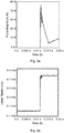
Fig. 3a is a graph showing force magnitude of the movable member in operation; and -
Fig. 3b is a graph showing the linear speed of the piston in operation. - The inventive concept will now be described more fully hereinafter with reference to the accompanying drawings, in which exemplifying embodiments are shown. The inventive concept may, however, be embodied in many different forms and should not be construed as limited to the embodiments set forth herein; rather, these embodiments are provided by way of example so that this disclosure will be thorough and complete, and will fully convey the scope of the inventive concept to those skilled in the art. Like numbers refer to like elements throughout the description.
-
Fig. 1 shows an example of a contactbounce reduction system 1. The contactbounce reduction system 1 may be for an electrical device such as a contactor or a tap changer. - The contact bounce reduction system comprises a contact
bounce damping device 2. - The contact
bounce damping device 2 comprises a body 3 and apiston 5. The body 3 has apiston channel 7 in which thepiston 5 is arranged. The body 3 has an opening that forms the mouth of thepiston channel 7. Thepiston 5 extends from thepiston channel 7 and the body 3. - The
piston 5 may be electrically conductive. Thepiston 5 may for example be made of metal such as copper or aluminium. - The
piston 5 is configured to be linearly movable relative to the body 3. Thepiston 5 is configured to be moved linearly in thepiston channel 7. Thepiston 5 is configured to be moved linearly between a default extended position relative to the body 3, shown inFig. 1 , and a retracted position. Thepiston 5 extends further from the body 3 in the default extended position than in the retracted position. - The
piston 5 has anexternal end portion 5a arranged outside the body 3 both in the default extended position and in the retracted position of thepiston 5. Thepiston 5 has aninternal end portion 5b arranged inside the body 3 both in the default extended position and in the retracted position of thepiston 5. - The
piston 5 is provided with aradial seat 5c. Theinternal end portion 5b of thepiston 5 is provided with theseat 5c. Theseat 5c extends radially inwards. Theseat 5c may be formed by a single recess extending circumferentially around thepiston 5 or it may comprise two individual recesses. - The
seat 5c may have a curved shape in a longitudinal section of thepiston 5. The curved shape may for example be a circular arc. - The contact
bounce damping device 2 comprises a first ball 9 and asecond ball 11. The first ball 9 and thesecond ball 11 are arranged in the body 3. The first ball 9 may for example be made of metal. Thesecond ball 11 may for example be made of metal. - The
seat 5c is configured to partly receive the first ball 9. Theseat 5c is configured to partly receive thesecond ball 11. The curved shape of theseat 5c may be configured to bear against at least 1/8th of the circumference of the first ball 9 and of thesecond ball 11 when the first ball 9 and thesecond ball 11 are arranged in theseat 5c, in a longitudinal section of thepiston 5. - The first ball 9 and the
second ball 11 are aligned in the radial direction of thepiston 5. The first ball 9 and thesecond ball 11 are arranged opposite to each other relative to the longitudinal axis A of thepiston 5. The first ball 9 is thus arranged on one side of the longitudinal axis A and thesecond ball 11 is arranged on another side of the longitudinal axis A, opposite to each other. - The contact
bounce damping device 2 comprises a firstresilient member 13. The firstresilient member 13 may be a spring such as a coil spring. The contactbounce reduction system 1 comprises a secondresilient member 15. The secondresilient member 15 may be a spring such as a coil spring. - The first
resilient member 13 has a longitudinal axis B which is transversal to the longitudinal axis A of thepiston 5. The longitudinal axis B may be perpendicular to the longitudinal axis A of thepiston 5. - The second
resilient member 15 has a longitudinal axis C which is transversal to the longitudinal axis A of thepiston 5. The longitudinal axis C may be perpendicular to the longitudinal axis A of thepiston 5. - The longitudinal axis B of the first
resilient member 13 may be parallel with the longitudinal axis C of the secondresilient member 15. The longitudinal axis B of the firsresilient member 13 may coincide with the longitudinal axis C of the secondresilient member 15. - The first
resilient member 13 is configured to act with a radial force onto the first ball 9. With the term "radial" is meant a direction that is perpendicular to the longitudinal axis A of thepiston 5. When thepiston 5 is in the default extended position the firstresilient member 13 is configured to force the first ball 9 into theseat 5c. - The second
resilient member 15 is configured to act with a radial force onto thesecond ball 11. When thepiston 5 is in the default extended position the secondresilient member 15 is configured to force thesecond ball 11 into theseat 5c. - The contact
bounce damping device 2 comprises a thirdresilient member 17. The thirdresilient member 17 is configured to bias thepiston 5 towards the default extended position. The thirdresilient member 17 is configured to accumulate energy when thepiston 5 is moved from the default extended position towards the retracted position. - The third
resilient member 17 has a longitudinal axis D which is parallel with the longitudinal axis A of thepiston 5. The longitudinal axis D of the thirdresilient member 17 may coincide with the longitudinal axis A of thepiston 5. - The first ball 9 and the
second ball 11 maintain thepiston 5 in the default extended position until a force greater than a threshold value acts on thepiston 5 in a direction from the default extended position towards the retracted position. - The contact
bounce reduction system 1 comprises amovable member 19. Themovable member 19 will in the following be exemplified by a movable contact but could alternatively be a movable member that forms part of a damper. Themovable contact 19 is configured to actuate thepiston 5 from the default extended position to the retracted position. Themovable contact 19 is configured to be moved relative to the body 3 and thepiston 5. Themovable contact 19 is configured to move from a non-contact position, shown inFig. 1 relative to thepiston 5 to a position in which it is in contact with thepiston 5. Thepiston 5 has ahead 5d and themovable contact 19 is configured to move from the non-contact position to a position in which it contacts thehead 5d. Themovable contact 19 is configured to actuate thepiston 5 when in contact with thehead 5d. Themovable contact 19 is configured to actuate thepiston 5 from the default extended position to the retracted position. Themovable contact 19 is configured to apply a force onto thehead 5d greater than the required threshold value to move thepiston 5 from the default extended position to the retracted position. - The
head 5d may comprise a material with a high resistance to erosion from arcing. Thehead 5d may for example comprise a copper tungsten alloy. - The contact
bounce damping device 2 may comprise athird ball 21 arranged in the body 3. Thethird ball 21 is arranged between theinner end face 5e of thepiston 5 and the thirdresilient member 17. The thirdresilient member 17 is configured to bias thethird ball 21 towards theinner end face 5e of thepiston 5. Thus, when thepiston 5 is impacted by themovable member 19 and moved towards the retracted position thethird ball 21 at impact with thepiston 5 absorbs energy and is subsequently moved together with thepiston 5 as the thirdresilient member 17 is compressed and accumulates energy. - The body 3 has a
first channel 23 in which the firstresilient member 13 is arranged. The body 3 has asecond channel 25 in which the secondresilient member 15 is arranged. Thefirst channel 23 and thesecond channel 25 may be arranged perpendicular to the longitudinal axis A of thepiston 5 and opposite to each other. - The first
resilient member 13 has a proximal end which bears against the first ball 9. - The contact
bounce damping device 2 may comprise a first holdingmember 27 configured to be arranged in thefirst channel 23 and configured to bear against a distal end of the firstresilient member 13. The firstresilient member 13 is thereby set in compression to act with a predetermined force on the first ball 9, determined by the spring constant and the size of the first holdingmember 27. The first holdingmember 27 may be threadedly engaged with the body 3 to facilitate removal of the first holdingmember 27 from the body 3. The first holdingmember 27 may for example be a bolt. - The second
resilient member 15 has a proximal end which bears against thesecond ball 11. - The contact
bounce damping device 2 may comprise a second holdingmember 29 configured to be arranged in thesecond channel 25 and configured to bear against a distal end of the secondresilient member 15. The secondresilient member 15 is thereby set in compression to act with a predetermined force on thesecond ball 11, determined by the spring constant and the size of the second holdingmember 29. The second holdingmember 29 may be threadedly engaged with the body 3 to facilitate removal of the second holdingmember 29 from the body 3. The second holdingmember 29 may for example be a bolt. - The body 3 has a
third channel 23 in which the thirdresilient member 17 is arranged. Thethird channel 23 and the thirdresilient member 17 share the same longitudinal axis D. - The contact
bounce damping device 2 may comprise a third holdingmember 31 configured to be arranged in thethird channel 30 and configured to bear against a distal end of the thirdresilient member 17. The thirdresilient member 17 is thereby set in compression to act with a predetermined force directly on thepiston 5 or via thethird ball 21, determined by the spring constant and the size of the third holdingmember 31. The third holdingmember 31 may be threadedly engaged with the body 3 to facilitate removal of the third holdingmember 31 from the body 3. The third holdingmember 31 may for example be a bolt or a sleeve. - As an alternative to the first holding
member 27, the second holdingmember 29 and the third holdingmember 31, the firstresilient member 13, the secondresilient member 15 and the thirdresilient member 17 could be arranged in a respective closed inner chamber in the body. In this case, no holding members would be required. The holdingmembers bounce damping device 2. - The contact
bounce damping device 2 may comprise acontact ring 33 slidably arranged around and in electrical contact with thepiston 5. Thecontact ring 33 may be electrically conducting. Thecontact ring 33 may be made of metal such as copper or aluminium. Thecontact ring 33 may be arranged in thepiston channel 7. - The contact
bounce damping device 2 may comprise a fixedcontact member 35 electrically connected to thecontact ring 33. - The
movable contact 19 may be configured to carry a current. When themovable contact 19 contacts thepiston 5 a closed circuit may be achieved, and the current may flow from themovable contact 19 to the piston and further to the fixedcontact member 35 via thecontact ring 33. - The operation of the contact
bounce reduction system 1 will now be described with reference toFig. 2 andFigs 3a-3b . - In
Fig. 1 themovable contact 19 is arranged in the non-contact position. The first ball 9 and thesecond ball 11 are resting in theseat 5c. - In
Fig. 2 themovable contact 19 is moved from the non-contact position to a position in which is in contact with thepiston 5. The actuation of themovable contact 19 may be electrical or mechanical, as is known to the skilled person. Thepiston 5 is thus moved from the default extended position shown inFig. 1 to the retracted position shown inFig. 2 . The force applied by themovable contact 19 is greater than a threshold value, which is determined by the design of the first, second and third resilient members and their state of compression in the body 3 in the default extended position of thepiston 5. - As the
piston 5 is being subjected to the force applied by the movable contact, the first ball 9 and thesecond ball 11 will eventually move out from theseat 5c. This initial high force required to move thepiston 5 is illustrated inFig. 3a , where the x-axis shows the time and the y-axis shows the force magnitude. When the first ball 9 and the second ball 9 has moved out from theseat 5c, thepiston 5 is moved axially. Thepiston 5 compresses the thirdresilient member 17 and causes thethird ball 21, if present, to move in the same direction as thepiston 5. The speed of thepiston 5 is shown inFig. 3b during this process. The acceleration is very fast and occurs at the same time as the large force is applied as shown inFig. 3a . While the force applied by themovable contact 19 is reduced after the first ball 9 and thesecond ball 11 has been moved out from theseat 5c the speed remains substantially constant as the piston is moved to the retracted position. - The contact bounce reduction system may according to some embodiments comprise more than two balls configured to act radially on the piston. The contact bounce reduction system may for example comprise 2∗N, N=2, 3, 4, 5..., k balls and N seats configured to receive pairs of balls. The contact bounce reduction system may comprise 2∗N resilient members, each configured to act with a radial force onto the corresponding ball to hold the ball in the corresponding seat when the piston is in the default extended position.
- In this manner, sequential radial pairwise movement of balls out from the corresponding seats may for example be achieved. This may provide further control on the initial force to move the piston and the speed of the piston.
- The contact
bounce reduction system 1 may form part of an electrical device such as a contactor or a tap changer for a transformer such as a distribution transformer or a power transformer. - The inventive concept has mainly been described above with reference to a few examples. However, as is readily appreciated by a person skilled in the art, other embodiments than the ones disclosed above are equally possible within the scope of the inventive concept, as defined by the appended claims.
Claims (13)
- A contact bounce reduction system (1) comprising:- a movable member (19), and- a contact bounce damping device (2) comprising:a body (3),a first ball (9) and a second ball (11) arranged in the body (3),a first resilient member (13) and a second resilient member (15),a piston (5) partly arranged in and extending from the body (3), the piston (5) being configured to be moved linearly between a default extended position and a retracted position relative to the body (3), and wherein the piston (5) has a radial seat (5c) configured to partly receive the first ball (9) and the second ball (11),wherein the first resilient member (13) is configured to act with a radial force onto the first ball (9) to hold the first ball (9) in the seat (5c) when the piston (5) is in the default extended position,wherein the second resilient member (15) is configured to act with a radial force onto the second ball (11) to hold the second ball (11) in the seat (5c) when the piston (5) is in the default extended position, anda third resilient member (17) configured to bias the piston (5) towards the default extended position;wherein the movable member (19) is configured to move from a non-contact position relative to the piston (5) to contact the piston (5) and actuate the piston (5) from the default extended position towards the retracted position with a force greater than a threshold value, causing the first ball (9) and the second ball (11) to move radially out from the seat (5c), and the third resilient member (17) to accumulate energy.
- The contact bounce reduction system (1) as claimed in claim 1, wherein the first ball (9) and the second ball (11) are arranged on opposite sides of the piston (5) with respect to a longitudinal axis (A) of the piston (5).
- The contact bounce reduction system (1) as claimed in claim 1 or 2, where the first ball (9) and the second ball (11) are arranged opposite to each other with respect to the longitudinal axis (A) of the piston (5).
- The contact bounce reduction system (1) as claimed in any of the preceding claims, wherein the first resilient member (13) and the second resilient member (15) have longitudinal axes (B, C) that are perpendicular to a longitudinal axis (A) of the piston (5).
- The contact bounce reduction system (1) as claimed in any of the preceding claims, wherein the first resilient member (13) is a first spring and the second resilient member (15) is a second spring.
- The contact bounce reduction system (1) as claimed in any of the preceding claims, comprising a third ball (21) arranged axially between the third resilient member (17) and the piston (5), wherein the third resilient member (17) is configured to act with an axial force onto the third ball (21).
- The contact bounce reduction system (1) as claimed in any of the preceding claims, comprising a first holding member (27), and wherein the body (3) has a first channel (23) in which the first resilient member (13) is arranged, wherein the first holding member (27) is removably arranged in the first channel (23) to hold the first resilient member (13) in position to act on the first ball (9).
- The contact bounce reduction system (1) as claimed in any of the preceding claims, comprising a second holding member (29), and wherein the body (3) has a second channel (25) in which the second resilient member (15) is arranged, wherein the second holding member (29) is removably arranged in the second channel (25) to hold the second resilient member (15) in position to act on the second ball (11).
- The contact bounce reduction system (1) as claimed in any of the preceding claims, comprising a third holding member (31), and wherein the body (3) has a third channel (30) in which the third resilient member (17) is arranged, wherein the third holding member (31) is removably arranged in the third channel (30) to hold the third resilient member (17) in position to act on the piston (5).
- The contact bounce reduction system (1) as claimed in any of the preceding claims, comprising a contact ring (33) slidably arranged around the piston (5), and a fixed contact member (35) electrically connected to the contact ring (33).
- The contact bounce reduction system (1) as claimed in any of the preceding claims, wherein the seat (5c) has a curved shape configured to bear against at least 1/8th of the circumference of each of the first ball (9) and the second ball (11).
- An electrical device comprising the contact bounce reduction system (1) as claimed in any of the preceding claims.
- The electrical device as claimed in claim 12, wherein the electrical device is a contactor or a tap changer for a transformer.
Priority Applications (5)
| Application Number | Priority Date | Filing Date | Title |
|---|---|---|---|
| EP20179976.4A EP3926653B1 (en) | 2020-06-15 | 2020-06-15 | Contact bounce reduction system |
| PCT/EP2021/064404 WO2021254764A1 (en) | 2020-06-15 | 2021-05-28 | Contact bounce reduction system |
| US18/010,712 US11742157B2 (en) | 2020-06-15 | 2021-05-28 | Contact bounce reduction system |
| KR1020227042749A KR102526231B1 (en) | 2020-06-15 | 2021-05-28 | Contact bounce reduction system |
| CN202180042623.3A CN115769325B (en) | 2020-06-15 | 2021-05-28 | Contact Bounce Reduction System |
Applications Claiming Priority (1)
| Application Number | Priority Date | Filing Date | Title |
|---|---|---|---|
| EP20179976.4A EP3926653B1 (en) | 2020-06-15 | 2020-06-15 | Contact bounce reduction system |
Publications (2)
| Publication Number | Publication Date |
|---|---|
| EP3926653A1 true EP3926653A1 (en) | 2021-12-22 |
| EP3926653B1 EP3926653B1 (en) | 2024-08-14 |
Family
ID=71096567
Family Applications (1)
| Application Number | Title | Priority Date | Filing Date |
|---|---|---|---|
| EP20179976.4A Active EP3926653B1 (en) | 2020-06-15 | 2020-06-15 | Contact bounce reduction system |
Country Status (5)
| Country | Link |
|---|---|
| US (1) | US11742157B2 (en) |
| EP (1) | EP3926653B1 (en) |
| KR (1) | KR102526231B1 (en) |
| CN (1) | CN115769325B (en) |
| WO (1) | WO2021254764A1 (en) |
Citations (4)
| Publication number | Priority date | Publication date | Assignee | Title |
|---|---|---|---|---|
| DE1045511B (en) * | 1957-06-25 | 1958-12-04 | Licentia Gmbh | Gas pressure switch |
| US3180960A (en) * | 1962-09-26 | 1965-04-27 | Gen Electric | Bounce suppressing arrangement for electrical contacts |
| EP0641002A1 (en) * | 1993-08-30 | 1995-03-01 | Gec Alsthom T Et D Sa | High or medium high voltage circuit breaker with abutting contacts |
| DE102017113416B3 (en) * | 2017-06-19 | 2018-06-07 | Fixtest Prüfmittelbau GmbH | MICROSWITCH AND TEST SYSTEM |
Family Cites Families (9)
| Publication number | Priority date | Publication date | Assignee | Title |
|---|---|---|---|---|
| US5175403A (en) * | 1991-08-22 | 1992-12-29 | Cooper Power Systems, Inc. | Recloser means for reclosing interrupted high voltage electric circuit means |
| CN101454855B (en) * | 2006-05-19 | 2012-05-30 | 爱惜康内镜外科公司 | force control switch |
| EP1936645B1 (en) * | 2006-12-21 | 2013-07-03 | Defond Components Limited | Circuit interrupter that produces snap-action connection and disconnection between electrical contacts |
| US7294804B1 (en) * | 2007-03-29 | 2007-11-13 | Eaton Corporation | Energy dissipating spring seat |
| JP5297682B2 (en) | 2008-04-24 | 2013-09-25 | 株式会社明電舎 | Vacuum circuit breaker |
| DE102013221910A1 (en) | 2013-10-29 | 2015-04-30 | Siemens Aktiengesellschaft | Electric switch |
| DE102016115222B4 (en) * | 2016-06-30 | 2020-02-13 | Dehn Se + Co Kg | Short-circuiting device for use in low and medium voltage systems for property and personal protection |
| DE102017212066A1 (en) * | 2017-07-14 | 2019-01-17 | Siemens Aktiengesellschaft | Kontaktanpressanordnung |
| JP6801629B2 (en) * | 2017-10-31 | 2020-12-16 | オムロン株式会社 | Electromagnetic relay |
-
2020
- 2020-06-15 EP EP20179976.4A patent/EP3926653B1/en active Active
-
2021
- 2021-05-28 KR KR1020227042749A patent/KR102526231B1/en active Active
- 2021-05-28 US US18/010,712 patent/US11742157B2/en active Active
- 2021-05-28 CN CN202180042623.3A patent/CN115769325B/en active Active
- 2021-05-28 WO PCT/EP2021/064404 patent/WO2021254764A1/en not_active Ceased
Patent Citations (4)
| Publication number | Priority date | Publication date | Assignee | Title |
|---|---|---|---|---|
| DE1045511B (en) * | 1957-06-25 | 1958-12-04 | Licentia Gmbh | Gas pressure switch |
| US3180960A (en) * | 1962-09-26 | 1965-04-27 | Gen Electric | Bounce suppressing arrangement for electrical contacts |
| EP0641002A1 (en) * | 1993-08-30 | 1995-03-01 | Gec Alsthom T Et D Sa | High or medium high voltage circuit breaker with abutting contacts |
| DE102017113416B3 (en) * | 2017-06-19 | 2018-06-07 | Fixtest Prüfmittelbau GmbH | MICROSWITCH AND TEST SYSTEM |
Also Published As
| Publication number | Publication date |
|---|---|
| KR102526231B1 (en) | 2023-04-26 |
| CN115769325A (en) | 2023-03-07 |
| KR20230003585A (en) | 2023-01-06 |
| US20230197364A1 (en) | 2023-06-22 |
| EP3926653B1 (en) | 2024-08-14 |
| US11742157B2 (en) | 2023-08-29 |
| CN115769325B (en) | 2023-07-04 |
| WO2021254764A1 (en) | 2021-12-23 |
Similar Documents
| Publication | Publication Date | Title |
|---|---|---|
| JP5178644B2 (en) | Gas circuit breaker with input resistance contact and its input / output method | |
| EP2492937B1 (en) | Switching apparatus | |
| US9455098B2 (en) | Electrical circuit switch with variable gear ratio | |
| EP3791086B1 (en) | Switch device | |
| WO2021047795A1 (en) | Vacuum circuit breaker operating mechanism | |
| KR20130004884A (en) | Electrical high-voltage on-load disconnector and method for opening the same | |
| JP5019461B2 (en) | Contact system for electrical switching devices | |
| EP3926653B1 (en) | Contact bounce reduction system | |
| CN109690723B (en) | Short-circuiting device for the protection of objects and persons, for use in low-or medium-voltage installations | |
| JP2024520772A (en) | Switching Device | |
| CN102610426B (en) | switch | |
| US6259050B1 (en) | Burn-off contact arrangement | |
| EP4481785A1 (en) | Switching device | |
| EP4348690B1 (en) | Switching device and method for operating a switching device | |
| EP4254461A1 (en) | Electromagnetic actuator | |
| US6236010B1 (en) | Circuit interrupter including a penetrating electrical contact with grip and release structure | |
| US7679021B2 (en) | Switching device | |
| KR101172751B1 (en) | Vaccum Interrupter For Ultra-High Voltage | |
| CN119317989B (en) | Contact assembly | |
| US20250069832A1 (en) | Dual-contact power contactor | |
| EP2717283B1 (en) | Electrical switching device with multiple nominal contacts and method for manufacturing the electrical switching device | |
| KR101155598B1 (en) | High Pressure Disconnector Structure | |
| JP2779055B2 (en) | Contact device | |
| JP2019110009A (en) | Switch | |
| EP3091547B1 (en) | Circuit breaker |
Legal Events
| Date | Code | Title | Description |
|---|---|---|---|
| PUAI | Public reference made under article 153(3) epc to a published international application that has entered the european phase |
Free format text: ORIGINAL CODE: 0009012 |
|
| STAA | Information on the status of an ep patent application or granted ep patent |
Free format text: STATUS: THE APPLICATION HAS BEEN PUBLISHED |
|
| AK | Designated contracting states |
Kind code of ref document: A1 Designated state(s): AL AT BE BG CH CY CZ DE DK EE ES FI FR GB GR HR HU IE IS IT LI LT LU LV MC MK MT NL NO PL PT RO RS SE SI SK SM TR |
|
| B565 | Issuance of search results under rule 164(2) epc |
Effective date: 20201216 |
|
| RAP3 | Party data changed (applicant data changed or rights of an application transferred) |
Owner name: HITACHI ENERGY SWITZERLAND AG |
|
| STAA | Information on the status of an ep patent application or granted ep patent |
Free format text: STATUS: REQUEST FOR EXAMINATION WAS MADE |
|
| 17P | Request for examination filed |
Effective date: 20220620 |
|
| RBV | Designated contracting states (corrected) |
Designated state(s): AL AT BE BG CH CY CZ DE DK EE ES FI FR GB GR HR HU IE IS IT LI LT LU LV MC MK MT NL NO PL PT RO RS SE SI SK SM TR |
|
| P01 | Opt-out of the competence of the unified patent court (upc) registered |
Effective date: 20230527 |
|
| RIN1 | Information on inventor provided before grant (corrected) |
Inventor name: KRAINER, PER |
|
| GRAP | Despatch of communication of intention to grant a patent |
Free format text: ORIGINAL CODE: EPIDOSNIGR1 |
|
| STAA | Information on the status of an ep patent application or granted ep patent |
Free format text: STATUS: GRANT OF PATENT IS INTENDED |
|
| GRAJ | Information related to disapproval of communication of intention to grant by the applicant or resumption of examination proceedings by the epo deleted |
Free format text: ORIGINAL CODE: EPIDOSDIGR1 |
|
| STAA | Information on the status of an ep patent application or granted ep patent |
Free format text: STATUS: REQUEST FOR EXAMINATION WAS MADE |
|
| RAP1 | Party data changed (applicant data changed or rights of an application transferred) |
Owner name: HITACHI ENERGY LTD |
|
| INTG | Intention to grant announced |
Effective date: 20231128 |
|
| INTC | Intention to grant announced (deleted) | ||
| GRAP | Despatch of communication of intention to grant a patent |
Free format text: ORIGINAL CODE: EPIDOSNIGR1 |
|
| STAA | Information on the status of an ep patent application or granted ep patent |
Free format text: STATUS: GRANT OF PATENT IS INTENDED |
|
| INTG | Intention to grant announced |
Effective date: 20240318 |
|
| GRAS | Grant fee paid |
Free format text: ORIGINAL CODE: EPIDOSNIGR3 |
|
| GRAA | (expected) grant |
Free format text: ORIGINAL CODE: 0009210 |
|
| STAA | Information on the status of an ep patent application or granted ep patent |
Free format text: STATUS: THE PATENT HAS BEEN GRANTED |
|
| AK | Designated contracting states |
Kind code of ref document: B1 Designated state(s): AL AT BE BG CH CY CZ DE DK EE ES FI FR GB GR HR HU IE IS IT LI LT LU LV MC MK MT NL NO PL PT RO RS SE SI SK SM TR |
|
| REG | Reference to a national code |
Ref country code: GB Ref legal event code: FG4D |
|
| REG | Reference to a national code |
Ref country code: CH Ref legal event code: EP |
|
| REG | Reference to a national code |
Ref country code: DE Ref legal event code: R096 Ref document number: 602020035633 Country of ref document: DE |
|
| REG | Reference to a national code |
Ref country code: IE Ref legal event code: FG4D |
|
| REG | Reference to a national code |
Ref country code: LT Ref legal event code: MG9D |
|
| REG | Reference to a national code |
Ref country code: NL Ref legal event code: MP Effective date: 20240814 |
|
| PG25 | Lapsed in a contracting state [announced via postgrant information from national office to epo] |
Ref country code: NO Free format text: LAPSE BECAUSE OF FAILURE TO SUBMIT A TRANSLATION OF THE DESCRIPTION OR TO PAY THE FEE WITHIN THE PRESCRIBED TIME-LIMIT Effective date: 20241114 |
|
| REG | Reference to a national code |
Ref country code: AT Ref legal event code: MK05 Ref document number: 1714095 Country of ref document: AT Kind code of ref document: T Effective date: 20240814 |
|
| PG25 | Lapsed in a contracting state [announced via postgrant information from national office to epo] |
Ref country code: FI Free format text: LAPSE BECAUSE OF FAILURE TO SUBMIT A TRANSLATION OF THE DESCRIPTION OR TO PAY THE FEE WITHIN THE PRESCRIBED TIME-LIMIT Effective date: 20240814 Ref country code: NL Free format text: LAPSE BECAUSE OF FAILURE TO SUBMIT A TRANSLATION OF THE DESCRIPTION OR TO PAY THE FEE WITHIN THE PRESCRIBED TIME-LIMIT Effective date: 20240814 Ref country code: PT Free format text: LAPSE BECAUSE OF FAILURE TO SUBMIT A TRANSLATION OF THE DESCRIPTION OR TO PAY THE FEE WITHIN THE PRESCRIBED TIME-LIMIT Effective date: 20241216 Ref country code: PL Free format text: LAPSE BECAUSE OF FAILURE TO SUBMIT A TRANSLATION OF THE DESCRIPTION OR TO PAY THE FEE WITHIN THE PRESCRIBED TIME-LIMIT Effective date: 20240814 Ref country code: GR Free format text: LAPSE BECAUSE OF FAILURE TO SUBMIT A TRANSLATION OF THE DESCRIPTION OR TO PAY THE FEE WITHIN THE PRESCRIBED TIME-LIMIT Effective date: 20241115 |
|
| PG25 | Lapsed in a contracting state [announced via postgrant information from national office to epo] |
Ref country code: LV Free format text: LAPSE BECAUSE OF FAILURE TO SUBMIT A TRANSLATION OF THE DESCRIPTION OR TO PAY THE FEE WITHIN THE PRESCRIBED TIME-LIMIT Effective date: 20240814 |
|
| PG25 | Lapsed in a contracting state [announced via postgrant information from national office to epo] |
Ref country code: AT Free format text: LAPSE BECAUSE OF FAILURE TO SUBMIT A TRANSLATION OF THE DESCRIPTION OR TO PAY THE FEE WITHIN THE PRESCRIBED TIME-LIMIT Effective date: 20240814 Ref country code: IS Free format text: LAPSE BECAUSE OF FAILURE TO SUBMIT A TRANSLATION OF THE DESCRIPTION OR TO PAY THE FEE WITHIN THE PRESCRIBED TIME-LIMIT Effective date: 20241214 |
|
| PG25 | Lapsed in a contracting state [announced via postgrant information from national office to epo] |
Ref country code: HR Free format text: LAPSE BECAUSE OF FAILURE TO SUBMIT A TRANSLATION OF THE DESCRIPTION OR TO PAY THE FEE WITHIN THE PRESCRIBED TIME-LIMIT Effective date: 20240814 |
|
| PG25 | Lapsed in a contracting state [announced via postgrant information from national office to epo] |
Ref country code: RS Free format text: LAPSE BECAUSE OF FAILURE TO SUBMIT A TRANSLATION OF THE DESCRIPTION OR TO PAY THE FEE WITHIN THE PRESCRIBED TIME-LIMIT Effective date: 20241114 Ref country code: ES Free format text: LAPSE BECAUSE OF FAILURE TO SUBMIT A TRANSLATION OF THE DESCRIPTION OR TO PAY THE FEE WITHIN THE PRESCRIBED TIME-LIMIT Effective date: 20240814 |
|
| PG25 | Lapsed in a contracting state [announced via postgrant information from national office to epo] |
Ref country code: RS Free format text: LAPSE BECAUSE OF FAILURE TO SUBMIT A TRANSLATION OF THE DESCRIPTION OR TO PAY THE FEE WITHIN THE PRESCRIBED TIME-LIMIT Effective date: 20241114 Ref country code: PT Free format text: LAPSE BECAUSE OF FAILURE TO SUBMIT A TRANSLATION OF THE DESCRIPTION OR TO PAY THE FEE WITHIN THE PRESCRIBED TIME-LIMIT Effective date: 20241216 Ref country code: PL Free format text: LAPSE BECAUSE OF FAILURE TO SUBMIT A TRANSLATION OF THE DESCRIPTION OR TO PAY THE FEE WITHIN THE PRESCRIBED TIME-LIMIT Effective date: 20240814 Ref country code: NO Free format text: LAPSE BECAUSE OF FAILURE TO SUBMIT A TRANSLATION OF THE DESCRIPTION OR TO PAY THE FEE WITHIN THE PRESCRIBED TIME-LIMIT Effective date: 20241114 Ref country code: NL Free format text: LAPSE BECAUSE OF FAILURE TO SUBMIT A TRANSLATION OF THE DESCRIPTION OR TO PAY THE FEE WITHIN THE PRESCRIBED TIME-LIMIT Effective date: 20240814 Ref country code: LV Free format text: LAPSE BECAUSE OF FAILURE TO SUBMIT A TRANSLATION OF THE DESCRIPTION OR TO PAY THE FEE WITHIN THE PRESCRIBED TIME-LIMIT Effective date: 20240814 Ref country code: IS Free format text: LAPSE BECAUSE OF FAILURE TO SUBMIT A TRANSLATION OF THE DESCRIPTION OR TO PAY THE FEE WITHIN THE PRESCRIBED TIME-LIMIT Effective date: 20241214 Ref country code: HR Free format text: LAPSE BECAUSE OF FAILURE TO SUBMIT A TRANSLATION OF THE DESCRIPTION OR TO PAY THE FEE WITHIN THE PRESCRIBED TIME-LIMIT Effective date: 20240814 Ref country code: GR Free format text: LAPSE BECAUSE OF FAILURE TO SUBMIT A TRANSLATION OF THE DESCRIPTION OR TO PAY THE FEE WITHIN THE PRESCRIBED TIME-LIMIT Effective date: 20241115 Ref country code: FI Free format text: LAPSE BECAUSE OF FAILURE TO SUBMIT A TRANSLATION OF THE DESCRIPTION OR TO PAY THE FEE WITHIN THE PRESCRIBED TIME-LIMIT Effective date: 20240814 Ref country code: ES Free format text: LAPSE BECAUSE OF FAILURE TO SUBMIT A TRANSLATION OF THE DESCRIPTION OR TO PAY THE FEE WITHIN THE PRESCRIBED TIME-LIMIT Effective date: 20240814 Ref country code: AT Free format text: LAPSE BECAUSE OF FAILURE TO SUBMIT A TRANSLATION OF THE DESCRIPTION OR TO PAY THE FEE WITHIN THE PRESCRIBED TIME-LIMIT Effective date: 20240814 |
|
| PG25 | Lapsed in a contracting state [announced via postgrant information from national office to epo] |
Ref country code: DK Free format text: LAPSE BECAUSE OF FAILURE TO SUBMIT A TRANSLATION OF THE DESCRIPTION OR TO PAY THE FEE WITHIN THE PRESCRIBED TIME-LIMIT Effective date: 20240814 Ref country code: RO Free format text: LAPSE BECAUSE OF FAILURE TO SUBMIT A TRANSLATION OF THE DESCRIPTION OR TO PAY THE FEE WITHIN THE PRESCRIBED TIME-LIMIT Effective date: 20240814 Ref country code: SM Free format text: LAPSE BECAUSE OF FAILURE TO SUBMIT A TRANSLATION OF THE DESCRIPTION OR TO PAY THE FEE WITHIN THE PRESCRIBED TIME-LIMIT Effective date: 20240814 |
|
| PG25 | Lapsed in a contracting state [announced via postgrant information from national office to epo] |
Ref country code: EE Free format text: LAPSE BECAUSE OF FAILURE TO SUBMIT A TRANSLATION OF THE DESCRIPTION OR TO PAY THE FEE WITHIN THE PRESCRIBED TIME-LIMIT Effective date: 20240814 |
|
| PG25 | Lapsed in a contracting state [announced via postgrant information from national office to epo] |
Ref country code: CZ Free format text: LAPSE BECAUSE OF FAILURE TO SUBMIT A TRANSLATION OF THE DESCRIPTION OR TO PAY THE FEE WITHIN THE PRESCRIBED TIME-LIMIT Effective date: 20240814 |
|
| PG25 | Lapsed in a contracting state [announced via postgrant information from national office to epo] |
Ref country code: IT Free format text: LAPSE BECAUSE OF FAILURE TO SUBMIT A TRANSLATION OF THE DESCRIPTION OR TO PAY THE FEE WITHIN THE PRESCRIBED TIME-LIMIT Effective date: 20240814 Ref country code: SK Free format text: LAPSE BECAUSE OF FAILURE TO SUBMIT A TRANSLATION OF THE DESCRIPTION OR TO PAY THE FEE WITHIN THE PRESCRIBED TIME-LIMIT Effective date: 20240814 |
|
| REG | Reference to a national code |
Ref country code: DE Ref legal event code: R097 Ref document number: 602020035633 Country of ref document: DE |
|
| PLBE | No opposition filed within time limit |
Free format text: ORIGINAL CODE: 0009261 |
|
| STAA | Information on the status of an ep patent application or granted ep patent |
Free format text: STATUS: NO OPPOSITION FILED WITHIN TIME LIMIT |
|
| 26N | No opposition filed |
Effective date: 20250515 |
|
| PG25 | Lapsed in a contracting state [announced via postgrant information from national office to epo] |
Ref country code: SE Free format text: LAPSE BECAUSE OF FAILURE TO SUBMIT A TRANSLATION OF THE DESCRIPTION OR TO PAY THE FEE WITHIN THE PRESCRIBED TIME-LIMIT Effective date: 20240814 |
|
| REG | Reference to a national code |
Ref country code: CH Ref legal event code: H13 Free format text: ST27 STATUS EVENT CODE: U-0-0-H10-H13 (AS PROVIDED BY THE NATIONAL OFFICE) Effective date: 20260127 |
|
| PG25 | Lapsed in a contracting state [announced via postgrant information from national office to epo] |
Ref country code: MC Free format text: LAPSE BECAUSE OF FAILURE TO SUBMIT A TRANSLATION OF THE DESCRIPTION OR TO PAY THE FEE WITHIN THE PRESCRIBED TIME-LIMIT Effective date: 20240814 |
|
| PG25 | Lapsed in a contracting state [announced via postgrant information from national office to epo] |
Ref country code: LU Free format text: LAPSE BECAUSE OF NON-PAYMENT OF DUE FEES Effective date: 20250615 |
|
| GBPC | Gb: european patent ceased through non-payment of renewal fee |
Effective date: 20250615 |
|
| REG | Reference to a national code |
Ref country code: BE Ref legal event code: MM Effective date: 20250630 |
|
| PG25 | Lapsed in a contracting state [announced via postgrant information from national office to epo] |
Ref country code: GB Free format text: LAPSE BECAUSE OF NON-PAYMENT OF DUE FEES Effective date: 20250615 |
|
| PG25 | Lapsed in a contracting state [announced via postgrant information from national office to epo] |
Ref country code: IE Free format text: LAPSE BECAUSE OF NON-PAYMENT OF DUE FEES Effective date: 20250615 |
|
| PG25 | Lapsed in a contracting state [announced via postgrant information from national office to epo] |
Ref country code: BE Free format text: LAPSE BECAUSE OF NON-PAYMENT OF DUE FEES Effective date: 20250630 |
|
| PG25 | Lapsed in a contracting state [announced via postgrant information from national office to epo] |
Ref country code: FR Free format text: LAPSE BECAUSE OF NON-PAYMENT OF DUE FEES Effective date: 20250630 |
|
| PG25 | Lapsed in a contracting state [announced via postgrant information from national office to epo] |
Ref country code: CH Free format text: LAPSE BECAUSE OF NON-PAYMENT OF DUE FEES Effective date: 20250630 |
|
| PG25 | Lapsed in a contracting state [announced via postgrant information from national office to epo] |
Ref country code: LT Free format text: LAPSE BECAUSE OF FAILURE TO SUBMIT A TRANSLATION OF THE DESCRIPTION OR TO PAY THE FEE WITHIN THE PRESCRIBED TIME-LIMIT Effective date: 20240814 |
|
| PGFP | Annual fee paid to national office [announced via postgrant information from national office to epo] |
Ref country code: DE Payment date: 20260622 Year of fee payment: 7 |
|
| PGFP | Annual fee paid to national office [announced via postgrant information from national office to epo] |
Ref country code: TR Payment date: 20260610 Year of fee payment: 7 |
|
| PGFP | Annual fee paid to national office [announced via postgrant information from national office to epo] |
Ref country code: BG Payment date: 20260619 Year of fee payment: 7 |
|
| PG25 | Lapsed in a contracting state [announced via postgrant information from national office to epo] |
Ref country code: CY Free format text: LAPSE BECAUSE OF FAILURE TO SUBMIT A TRANSLATION OF THE DESCRIPTION OR TO PAY THE FEE WITHIN THE PRESCRIBED TIME-LIMIT Effective date: 20240814 |