EP3926599A2 - Testvorrichtung und -system für einen detektor, der auf der detektion eines gases oder eines gas/teilchen-gemisches basiert - Google Patents
Testvorrichtung und -system für einen detektor, der auf der detektion eines gases oder eines gas/teilchen-gemisches basiert Download PDFInfo
- Publication number
- EP3926599A2 EP3926599A2 EP21180060.2A EP21180060A EP3926599A2 EP 3926599 A2 EP3926599 A2 EP 3926599A2 EP 21180060 A EP21180060 A EP 21180060A EP 3926599 A2 EP3926599 A2 EP 3926599A2
- Authority
- EP
- European Patent Office
- Prior art keywords
- test
- gas
- test device
- detector
- radio
- Prior art date
- Legal status (The legal status is an assumption and is not a legal conclusion. Google has not performed a legal analysis and makes no representation as to the accuracy of the status listed.)
- Withdrawn
Links
Images



Classifications
-
- G—PHYSICS
- G08—SIGNALLING
- G08B—SIGNALLING SYSTEMS, e.g. PERSONAL CALLING SYSTEMS; ORDER TELEGRAPHS; ALARM SYSTEMS
- G08B29/00—Checking or monitoring of signalling or alarm systems; Prevention or correction of operating errors, e.g. preventing unauthorised operation
- G08B29/12—Checking intermittently signalling or alarm systems
- G08B29/14—Checking intermittently signalling or alarm systems checking the detection circuits
- G08B29/145—Checking intermittently signalling or alarm systems checking the detection circuits of fire detection circuits
-
- G—PHYSICS
- G01—MEASURING; TESTING
- G01N—INVESTIGATING OR ANALYSING MATERIALS BY DETERMINING THEIR CHEMICAL OR PHYSICAL PROPERTIES
- G01N33/00—Investigating or analysing materials by specific methods not covered by groups G01N1/00 - G01N31/00
- G01N33/0004—Gaseous mixtures, e.g. polluted air
- G01N33/0009—General constructional details of gas analysers, e.g. portable test equipment
- G01N33/007—Arrangements to check the analyser
-
- G—PHYSICS
- G01—MEASURING; TESTING
- G01N—INVESTIGATING OR ANALYSING MATERIALS BY DETERMINING THEIR CHEMICAL OR PHYSICAL PROPERTIES
- G01N1/00—Sampling; Preparing specimens for investigation
- G01N1/28—Preparing specimens for investigation including physical details of (bio-)chemical methods covered elsewhere, e.g. G01N33/50, C12Q
- G01N1/38—Diluting, dispersing or mixing samples
-
- G—PHYSICS
- G08—SIGNALLING
- G08B—SIGNALLING SYSTEMS, e.g. PERSONAL CALLING SYSTEMS; ORDER TELEGRAPHS; ALARM SYSTEMS
- G08B17/00—Fire alarms; Alarms responsive to explosion
- G08B17/10—Actuation by presence of smoke or gases, e.g. automatic alarm devices for analysing flowing fluid materials by the use of optical means
-
- G—PHYSICS
- G08—SIGNALLING
- G08B—SIGNALLING SYSTEMS, e.g. PERSONAL CALLING SYSTEMS; ORDER TELEGRAPHS; ALARM SYSTEMS
- G08B25/00—Alarm systems in which the location of the alarm condition is signalled to a central station, e.g. fire or police telegraphic systems
- G08B25/01—Alarm systems in which the location of the alarm condition is signalled to a central station, e.g. fire or police telegraphic systems characterised by the transmission medium
- G08B25/10—Alarm systems in which the location of the alarm condition is signalled to a central station, e.g. fire or police telegraphic systems characterised by the transmission medium using wireless transmission systems
-
- G—PHYSICS
- G08—SIGNALLING
- G08B—SIGNALLING SYSTEMS, e.g. PERSONAL CALLING SYSTEMS; ORDER TELEGRAPHS; ALARM SYSTEMS
- G08B26/00—Alarm systems in which substations are interrogated in succession by a central station
- G08B26/006—Alarm systems in which substations are interrogated in succession by a central station with substations connected to an individual line, e.g. star configuration
-
- G—PHYSICS
- G08—SIGNALLING
- G08B—SIGNALLING SYSTEMS, e.g. PERSONAL CALLING SYSTEMS; ORDER TELEGRAPHS; ALARM SYSTEMS
- G08B26/00—Alarm systems in which substations are interrogated in succession by a central station
- G08B26/007—Wireless interrogation
-
- G—PHYSICS
- G01—MEASURING; TESTING
- G01N—INVESTIGATING OR ANALYSING MATERIALS BY DETERMINING THEIR CHEMICAL OR PHYSICAL PROPERTIES
- G01N21/00—Investigating or analysing materials by the use of optical means, i.e. using sub-millimetre waves, infrared, visible or ultraviolet light
- G01N21/17—Systems in which incident light is modified in accordance with the properties of the material investigated
- G01N21/59—Transmissivity
- G01N21/5907—Densitometers
- G01N2021/598—Features of mounting, adjusting
- G01N2021/5984—Features of mounting, adjusting height adjustable
-
- G—PHYSICS
- G01—MEASURING; TESTING
- G01N—INVESTIGATING OR ANALYSING MATERIALS BY DETERMINING THEIR CHEMICAL OR PHYSICAL PROPERTIES
- G01N33/00—Investigating or analysing materials by specific methods not covered by groups G01N1/00 - G01N31/00
- G01N33/0004—Gaseous mixtures, e.g. polluted air
- G01N33/0009—General constructional details of gas analysers, e.g. portable test equipment
- G01N33/007—Arrangements to check the analyser
- G01N33/0072—Arrangements to check the analyser by generating a test gas
-
- G—PHYSICS
- G08—SIGNALLING
- G08C—TRANSMISSION SYSTEMS FOR MEASURED VALUES, CONTROL OR SIMILAR SIGNALS
- G08C17/00—Arrangements for transmitting signals characterised by the use of a wireless electrical link
- G08C17/02—Arrangements for transmitting signals characterised by the use of a wireless electrical link using a radio link
Definitions
- the present invention relates to a test device for a detector based on the detection of gas or of a gas / particle mixture, in particular for an automatic fire detector (called “DAI”) based on the detection of smoke.
- DAI automatic fire detector
- the test device according to the invention is designed to be integral with the detector, to be energy independent and to be able to manage radio communication in order to trigger remotely, from a control means, the diffusion of the test gas or of the mixture. test gas / particles to the detector.
- the invention also relates to a test system which comprises one or more test device (s), a control network comprising a control means and at least one radio gateway connecting the test device (s) and the control unit.
- the invention also relates to a detector system comprising a test system and at least one detector.
- Scorpion ® -type test systems have been developed in which a tester is mounted next to a smoke-type fire detector, the tester comprising a support rail which is attached to the fire detector to be tested or to the base of which said fire detector is mounted, a body containing an aerosol and a nozzle connected to the body from which an aerosol jet generated by the tester is directed to the detection head of the fire detector.
- the tester uses its own independent power and data cables and uses a test control panel, separate from any preinstalled fire detection system and fire detection system control panel wiring.
- Several fire detectors are wired to a fixed control panel (control of 1 to 8 heads), or to a portable control panel via a terminal (control of 1 to 4 heads), all also wired.
- test system makes it possible to reach fire detectors located high up and difficult to reach and / or difficult to access, it is however necessary to equip each wired tester. Its installation is therefore relatively expensive due to the necessary deployment of the test system's own control and power cables. In addition, the action distance is limited to 100 meters. In addition, the tester requires the supply of a relatively large amount of energy during operation to generate the aerosol. Finally, due to the size of the Scorpion ® heads, the orientation of the tester affects the efficiency of the tests carried out, the tester being able only to be inserted in position along a certain axis (for example along a aisle), but the airflow there can oppose the passage of the aerosol to the sensing component, reducing the reliability of any test.
- the patent application EP2988282A1 also describes a fire detector in which is installed an RFID chip that allows communication and data transfer between the fire detector and a detector test tool this time without a pole, but this is also limited to the exchange of data and this, nearby. The test cannot therefore be controlled remotely.
- the proposed device comprises a light source for directing light into the lanes and one or more sensors positioned in the detector so as to be able to analyze the light which has entered. The device thus makes it possible to detect obstructions in the lanes by analyzing the way in which the light propagates through the lanes.
- each fire detector comprises in a base unit communication components allowing the detector to communicate with a control panel via a wired link (security communication network).
- the patent application GB2543065A describes this problem of obstruction, but rather addresses the disadvantages of Scorpio ® based systems described above. It describes a fire detector test device comprising a liquid reservoir and a vibrating mesh type aerosol generator in fluid connection with the liquid reservoir for generating an aerosol from the liquid reservoir, arranged such that, when generated, the aerosol is directed to the detector element of a fire detector.
- the self-test function is controlled by the safety communication network of the fire detectors, and it is incorporated into the detectors. fire, which requires changing all fire detectors to obtain this new function. It is therefore not a function that can easily be added to fire detectors.
- the invention aims to overcome the aforementioned drawbacks of the prior art.
- a universal test device for a fire detector and more generally for any detector based on the detection of gas or gas / particle mixture which can be easily adapted to any existing detector and / or already installed, which can be controlled remotely (in particular at more than 100 meters), which is particularly sought after for detectors located at a height, difficult to reach and / or difficult to access.
- a stand-alone test device is also sought, which makes it possible to do without poles, nacelles or other means for approaching the detector to be tested, and which makes it possible to do without the large quantity and length of cables.
- test system is also sought which is low in energy costs, which is quick to set up, and which is reliable.
- a test is also sought which is simple to implement, and which can in particular be implemented without an operator.
- the radio communication can be established with a control network comprising a control means, and this, through at least one radio gateway.
- test device can also include one or more of the following embodiments taken in isolation or in any technically possible combination.
- the container is suitable for receiving or is a test gas cartridge or a test gas particle mixture.
- the diffusion means comprises a diffuser configured to convey the test gas or the gas / test particle mixture as close as possible to the gas inlet of the detector.
- the diffusion means comprises an element capable of cooperating with the securing means.
- the test device further comprises an actuator that can be controlled remotely and able to actuate the diffusion of the test gas or of the gas / test particle mixture in the diffusion means, and thus in the detector.
- the securing means comprises at least one hooking finger, a first end of which has a hook shape capable of cooperating with a recess in the detector.
- the securing means comprises a fixing flange capable of gripping the detector.
- the securing means comprises means for adjusting the relative position of the test device with respect to the detector.
- the securing means further comprises at least one end suitable for adjusting the tightening or loosening of the fixing flange around the detector, said at least one end preferably being positioned in the axis of the detector. center of gravity of the test device.
- the local radio communication conforms to the LoRa technology
- the radio equipment comprises a component compatible with the LoRa technology, with a communication protocol based on the LoRaWAN protocol.
- the test device comprises a precise time base, for example a real time clock (RTC for “Real Time Clock”).
- RTC Real Time Clock
- the radio equipment preferably comprises a means for placing on standby and periodically waking up, the waking period being adaptable.
- the standby time can also be adaptable.
- the means for placing the test device on standby and periodically waking up is integrated in a software layer backed by the LoRaWAN layer of the radio equipment of the test device.
- radio gateway is meant a device making it possible to connect two communication networks of different types.
- the radio gateway makes it possible to connect the radio equipment and the control network comprising the control means.
- the term “gateway” designates by shorthand a radio gateway.
- Radio equipment helps to form a local radio network using one or more radio gateways.
- the local radio network designates the network formed by the test device (s), and the gateway (s).
- the radio equipment makes it possible to exchange information with the control network via a radio gateway, preferably in a bidirectional manner.
- the control network designates the network formed by the gateway (s) and the control unit, with the communication link connecting them, and may include other elements inserted between the gateway (s) ) and the control unit.
- the control network may include or consist of an IP computer network. It is recalled that an IP computer network is a communication network under Internet protocol (or “IP” for “Internet Protocol” in English). In the present description, the term “IP network” or “IP computer network” designates by shortcut a computer network using the Internet protocol. Likewise, an “IP link” or “IP communication link” or “communication link under IP” designates a communication link under Internet protocol.
- control network comprises a universal time broadcasting server capable of synchronizing with a time base in the test device, so as to have a common time base.
- control unit is able to give standby and wake-up instructions to the test device, the wake-up periodicity being adaptable.
- the standby time is also adaptable. This improves the autonomy of the test device.
- the control network can be an IP network, the control unit then comprising an IP layer, the control unit being for example a desktop computer, a laptop computer, a tablet, a smart phone, etc.
- the at least one network communication link is entirely wired.
- control network comprises a network concentrator and a communication interface having a communication protocol compatible with the radio equipment and the at least one radio gateway, generally an application concentrator.
- the local radio communication conforms to the LoRa technology
- the radio equipment of the test device comprises a component compatible with the LoRa technology, with a communication protocol based on the LoRaWAN protocol and the at least one radio gateway is a LoRaWAN gateway.
- control network comprises a network concentrator and an application concentrator.
- the means for placing the test device on standby and periodically waking up is integrated in a software layer backed up on the LoRaWAN layer of the radio equipment of the test device and on the application concentrator.
- control network comprises several communication links comprising a wired part connecting the at least one gateway, the network concentrator and the application concentrator, and a wireless part, for example in Wifi, connecting the. application hub and control unit.
- the control network can be an IP network, and the network communication links can be IP communication links.
- control network comprises several communication links comprising at least one IP communication link, wired and / or wireless, between the at least one gateway, the network concentrator and the application concentrator and at least one LoRa radio communication link between the at least one gateway and the control unit, the control unit comprising a portable device equipped with a radio component compatible with LoRa technology.
- test device and the test system according to the invention can include any one of the previously stated characteristics, taken in isolation or in any technically possible combination with other characteristics.
- the control unit can be included in or be associated with a supervision unit of one or more detectors.
- the invention also relates to a detection system comprising a test system according to the invention and a detector based on the detection of gas or of a gas / particle mixture.
- the detector is a fire detector based on the detection of smoke.
- test gas is used to describe indifferently: a gas, a mixture of different gases or even a mixture of gases and particles, suitable for testing a detector based on the detection of gas or of gas. gas / particle mixture.
- test device is described in the detailed description with reference to a smoke-type fire detector, which may be termed a "smoke detector", although it may apply to any other detector based on the detection. gas or gas / particle mixture, within the scope of the claims. The same is true for the test system and the detection system.
- the figures 1A and 1B illustrate a first embodiment of the test device according to the invention which is in the form of a main body 10 connected to a securing means 11.
- the main body can be made of plastic, metal or any other suitable material, preferably light and resistant to shocks and over time.
- the height of the main body of the illustrated test device is 14cm, its depth is about 4cm, and its width is about 5.5cm.
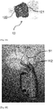
- the means of securing illustrated in figure 1A comprises at least one hooking finger 111, a first end 111A of which has a hook shape capable of cooperating with a recess in a detector (not shown in the figures 1A and 1B ).
- a smoke detector includes gas inlet openings, for example in the form of fins, through which smoke can enter the interior of the detector to reach the detection components. These openings can form one or more recesses in which (s) a catching finger can be inserted.
- the figures 2A and 2B illustrate two variants of securing means in the form of hooking fingers with two different types of fingers making it possible to adapt to two different types of detectors.
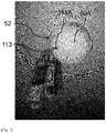
- FIG. 2A In a first variant, in figure 2A , are shown two fingers 112 whose first ends 112A are adapted to fit vertically between two vertical fins 51A of a first type of detector 51.
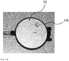
- FIG. 2B In a second variant, in figure 2B , are shown two fingers 113 whose first ends 113A are adapted to fit horizontally between two horizontal fins 52A of a second type of detector 52.
- the securing means in the form of hooking fingers are simple to implement and can be easily adapted to different detectors, for example by adapting the shape of the finger (or fingers) and in particular by adapting the shape of the end. finger (or fingers) intended to cooperate with the detector.
- the shapes described are not limiting and those skilled in the art will know how to adapt them to other types of detectors.
- detectors which do not include openings that are easy to pick up with one or more hooking finger (s), or detectors for which an attachment with the fingers would not be secure in the long term.
- the fingers can present areas of weakness, and can end up breaking after several hooks and drops.
- an attachment means may sometimes require too great a precision to attach the detector, which is not always easy to achieve in height.
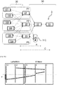
- the figure 3 illustrates a third variant in which a third type of detector 53 is shown, which does not include fins or openings that are easy to hook.
- the fastening means 115 illustrated is in the form of a clamp-type fixing flange which encircles and grips the detector 53.
- a fixing flange is suitable here for any type of detector of generally circular shape, but d Other flanges can be adapted for shapes that are not completely circular.
- the first fixing flange can be made of plastic, metallic material, or mixed material.
- the securing means described with reference to the figure 3 is illustrated with the third type of detector 53, but it can be adapted to any type of detector.
- the other elements of the test device can be identical to those described later in the present description.
- the ends 110C and 110D are advantageously positioned in the axis of the center of gravity of the test device. In this way, the test device is positioned naturally vertically throughout the process of gripping by the suction cups until it is placed around the detector. The installation is thus greatly facilitated.
- the first part 110A of the metal wire forming the height adjustment system is connected to the second part 110B of the metal wire by welding.
- the first part 110A of the metal wire can be connected to the second part 110B via the second end 110D by bending the metal wire at said second end (a single metal wire to form the whole).
- This mounting flange is said to be “universal” (in the sense that it is not designed for a single type of detector) and it is advantageous in that it allows the adjustment of the test device relative to the detector. Adjusting the height of the test device ensures that the diffuser is properly positioned opposite the gas inlet openings of the detector, for example in front of the fins when the detector is fitted with them. It is also advantageous by its ease of installation on the detector (in particular it aligns itself automatically around the latter by gravity). It is also advantageous because it can be easily removed: in fact, the suction cups or the pads do not need to be perfectly aligned to grip it.
- the securing means described with reference to the figures 4A and 4B is illustrated with the second type of detector 52, but it can be adapted to any type of detector.
- the other elements of the test device can be identical to those described later in the present description.
- the upper end of the main body 10 is open and is profiled to form a diffusion means 12 comprising a diffuser 121 sized to convey the test gas as close as possible to the head of the detector.
- the head of the detector designates the part of the detector which includes the detection components.
- the means of dissemination 12 detailed in figure 1B comprises a first part 121 forming the diffuser which has the form of an elbow duct connected to the container 13 of test gas and dimensioned to convey the test gas to the level of the openings of the detector, so that the test gas can reach the head of the detector.
- the curved duct diffuses the test gas by a venturi effect by entraining the test gas in the fins of the detector after a 90 ° deflection.
- a diffuser is defined as a static member making it possible to distribute a gas flow.
- the diffusion means 12 illustrated in figure 1B further comprises a second portion 122 profiled to cooperate with the securing means, for example with the second end 111B of the finger 111, as illustrated in figure 1A .
- the securing means can be permanently maintained on the detector and the rest of the test device can be secured or disconnected with said securing means, for example via this second part 122 of the diffusion means 12, by moving the diffusion means relatively by securing means, for example by sliding it so as to easily recover and reposition the diffusion means, for example during maintenance of the test device (for recharging the test gas cartridge in particular).
- the securing means preferably comprises at least three points of attachment with the detector (for example three fingers or a fixing flange, or even any other suitable means) to prevent that the diffuser does not come off in the event of vibration or shock (in the event of an earthquake, for example).
- a first compartment of the main body forms a container 13 sized to receive a gas cartridge containing the test gas, the cartridge being for example of the standard type and being able to include a valve located in the upper part of the cartridge.
- the container can be the gas cartridge, and the test device comprises a means for holding said cartridge.
- a standard aluminum cartridge with a capacity of 24 milliliters, a diameter of 25 millimeters and a length of 90 millimeters.
- the cartridge can be refillable or disposable.
- the type of gas used is smoke for a smoke detector tester (“SDT” for Smoke Detector Test), in the form of an aerosol.
- a second compartment 16 of the main body is adapted to receive an energy source 160 which can be an energy storage means (for example one or more batteries or a rechargeable battery or any other suitable means).
- an energy storage means for example one or more batteries or a rechargeable battery or any other suitable means.
- test device illustrated in figure 1 comprises an actuator 150 capable of actuating the introduction of the test gas from the gas cartridge into the diffuser (and thus of diffusing it into the detector).
- the actuator can be a solenoid valve or a mechanical actuator pressing the valve of the cartridge.
- the actuator fluidly connects the diffuser and the test gas cartridge. It can be placed in a third compartment 15 of the main body located between the diffusion means and the test gas container.
- the actuator 150 is connected to the power source 160 to be powered and to a card electronics 141 to be controlled.
- the electronic card is preferably dedicated to the actuator and must make it possible to ensure a sufficient inrush current for its correct operation.
- the actuator 150 can be a solenoid valve.
- the choice of a solenoid valve is preferred. Indeed, actuating the introduction of the test gas by mechanical action on the cartridge valve requires a significant effort to compress the valve spring (and in addition, this may lack precision in the amount of gas emitted, depending on the type of valve available on the cartridge).
- a solenoid valve can comprise on one of its ends a female socket fitted with a sealing O-ring and designed to be connected to the male part of the gas cartridge, and on its other end a cap to atomize the gas (for example thin hole in a metal plate).
- the radio equipment 140 is placed in a fourth compartment 14 of the main body forming an electronic part and sized to receive electronic equipment.
- the fourth compartment can also receive the electronic card 141 of the actuator 150.
- the local radio network between a test device and a gateway conforms to the LoRaWAN radio protocol.
- LoRaWAN is the acronym for "Long Range Wide-Area Network” in English which can be translated as “long-range wide-area network”.
- LoRaWAN enables long range communications at low cost and low power. This can be a low speed LoRaWAN communication protocol (0.3 to 50 kbps).
- the radio equipment 140 can then include an electronic card operating on LoRa radio technology, preferably operating around the frequency of 868 MHz (for Europe), 915 MHz (for the USA), or 780 MHz (for the United States). Asia), this frequency being a compromise between radio coverage and radio capacity.
- LoRa is the modulation technology related to LoRaWAN.
- the electronic card can be a LoRa development card of the Internet of Things ("IoT") type, for example a LoPy4 electronic card from the manufacturer Pycom, having a LoRaWAN radio module, or even a radio card incorporating a LoRa chip and developed specifically for the applications targeted by the invention so as to gain in efficiency, consumption, size and manufacturing cost.
- a radio antenna is connected to the LoRa development board via a connector or is printed directly on the electronic board containing the radio module so as to do without the cable and save space and cost.
- the radio equipment 140 can include any component compatible with LoRa technology.
- the electronic part 14 can also include a precise time base with very low energy consumption.
- This time base can be for example a real time clock (or “RTC” for Real Time Clock in English).
- the test device can easily be attached to a detector (using one (or more) hooking finger (s), a fixing flange, or using any other suitable means).
- the test device is made autonomous since it incorporates an energy source, a test gas cartridge.
- the test device preferably comprises an actuator for actuating the output of the test gas from the cartridge. towards the diffuser, the actuator being powered by the energy source, as well as an electronic device, such as an electronic card, for controlling the actuator.
- the test device comprises radio equipment, such as a LoRa radio module, which allows it to communicate remotely with a control unit located in a control network via a radio gateway (capable of connecting the local radio network and the network. control, preferably bidirectional). This communication is preferably carried out at time-stamped times, the time reference of which is ensured by the use of a precise time base with low energy consumption.
- the test device can thus operate on a remote control, via a radio protocol, a certain configurable quantity of test gas which diffuses at the level of the gas inlet openings of a detector so as to trigger said detector (including the alarm can be inhibited beforehand to carry out the test), and to test its operation remotely.
- the figure 5 illustrates a test system according to the invention, comprising a test device 1, a radio gateway 2 and a control network 3.
- a radio communication link 20 (represented by a double dotted arrow) wirelessly connects the test device 1 and the gateway 2.
- the communication between the test device and the gateway takes place bidirectionally.
- the control network 3 comprises at least one control unit 31 and a network communication link 30 between the control unit 31 and the radio gateway 2.
- the communication between the gateway and the control network takes place in such a manner. bidirectional.
- the network communication link 30 can be entirely wired (represented by a double arrow in solid lines).
- the network communication link 30 can be wireless (alternative represented by a double arrow in phantom).
- the gateway can use a WIFI terminal or an already existing cell station and thus communicate wirelessly with the control unit.
- the gateway can communicate with said such control unit according to a radio protocol, for example the same radio protocol as for the radio communication between the test device and the gateway.
- the radio control unit is suitable for this radio protocol.
- This can be a remote control with a radio component adapted to the radio protocol.
- Such a radio remote control can be arranged so as to control the test device from a shorter distance, for example in the room or in the building where the detector is located.
- the radio control unit is a LoRaWAN remote control, it is important to be able to approach the test device in order to observe the behavior of the detector when the test is triggered by the remote control.
- the network communication link can be mixed, that is to say with a wireless part and a wired part.
- the test system can include several test devices associated with as many detectors, and also several radio gateways, and a control network with a control unit, the control network being connected to the gateways by wired communication links, without- yarn or mixed.
- a gateway can act as a communication relay for several devices test, for example if the test devices are located within the radio coverage area of the gateway.
- the figures 6A-6B , 7A-7B and 8A-8B illustrate second, third and fourth embodiments of a test system having a star network architecture, comprising several test devices 101, 102, 103, 104, 105, 106 each being provided with radio equipment, and several gateways 21, 22, 23.
- the test devices and gateways are distributed over three different areas (three different rooms P1, P2 and P3).
- the test system comprises a network 3 connected to each of the gateways.
- the radio communication links 20 are represented by double dotted arrows.
- a network communication link 30 is represented by a double arrow in solid lines (wired) or a double arrow in phantom (wireless or mixed) or by a double arrow in dotted lines, if it is the same radio protocol as for the radio communication between the test device (s) and the gateway (s).
- the radio equipment of the test devices communicate bidirectionally with the radio gateways.
- the gateways preferably communicate bidirectionally with the control network. Bidirectionality is advantageous because it allows in one direction that a test device receives the actuation command and in the other direction that the test device acknowledges receipt of the command, confirms that the test has been carried out (for example if the test does not trigger the detector) and / or provides information on the level of the battery and / or the gas cartridge ...
- each test device and each gateway has a unique identifier so as to improve the security of the test system, in particular to authenticate the radio equipment items.
- An encryption mechanism can also be provided using a digital key sharing mechanism.
- the gateway 21 can serve as a communication relay for the test devices 101 and 102 of the same room P1, but also of the adjacent room P2.
- the gateway 23 can serve as a communication relay for the test devices 105 and 106 of the same room P3, but also of the adjacent room P2.
- the gateway 22 which is in the intermediate room P2 can serve as a communication relay for the six test devices which are in the three rooms.
- Each gateway is connected to the control network by a wired link.
- a gateway can be connected to the control network by a wireless link of the WIFI or cellular type, or even by a mixed link.
- the local radio network between the test devices and the gateways conforms to LoRa radio technology, around the frequency of 868 MHz, with a LoRaWAN communication protocol.
- the radio equipment of each test device comprises at least one LoRaWAN radio module incorporating a radio antenna so as to establish a LoRa radio link with one or more gateways, and the gateways are LoRaWAN gateways.
- Configuration parameters (among others) of the LoRa technology are the Spreading Factor ("Spreading Factor” or “SF” in English), the bandwidth (“Bandwidth” or “BW” in English) and channel coding (“Coding Rate” or “CR”). More particularly in a LoRaWAN architecture, with each of these spread spectrum factors SF, in a BW bandwidth of 125 kHz and a Coding Rate of 4/5, is associated a bit rate number (“DataRate” or “DR ») Ranging from 0 (lowest speed) to 5 (highest speed).
- the radio equipment which uses LoRA type technologies are advantageous in that they are generally electronic equipment with low consumption, small size and low radio transmission power, and allowing communication over long distances.
- a LoRaWAN radio module can establish a two-way radio link with one or more different gateways.
- a LoRaWAN radio module has a unique identifier.
- LoRaWAN gateways also all have a unique identifier and can simultaneously decode multiple frequency channels on multiple SF spread spectrum factors.
- the network communication links (or links) 30 can be TCP / IP links (transport layer / network layer), optionally with a protocol for securing exchanges on the Internet (SSL, TLS typically) arranged between the transport layer (TCP .. .) and the application layer (HTTP, FTP, SMTP, MQTT, ).
- a gateway On reception of a LoRaWAN frame coming from a radio module of a test device, a gateway transfers over the IP link (using the MQTT protocol in TCP / IP most often), a packet by adding radio information to it. : this is referred to as an “up” link. This information is intended for the network concentrator 32. In the other direction, that is to say in the so-called “downlink” link, the information is transferred from the network concentrator 32 to the radio module of a test device.
- Each LoRaWAN gateway thus has a “packet forwarder” function between a radio link using LoRa technology and an IP link, without implementing any particular intelligence or filtering.
- the main function of the network concentrator 32 (“network server” in English) is to remove the duplicates from the uplink information. Indeed, since a packet originating from radio equipment can be received simultaneously by several gateways, the information is duplicated. For downlink voice, the network hub selects a single gateway to send the packet.
- An authentication key A (for example of the “NwkSKey” type) can be used by the network concentrator to authenticate the radio equipment.
- the main functions of the application concentrator 33 are to authenticate and decrypt the uplink information from the network hub or the downlink information to the network hub.
- the application concentrator can, on a subsidiary basis, store information.
- the application concentrator can have decryption keys C (for example of the “AppSKey” type) shared with each of the radio equipment items of the test devices.
- Another optional function of the application hub is to decode (respectively encode) the radio frame.
- the Web application or server 34 is the last software brick, at the end of the chain, of a standard LoRaWAN architecture.
- the application makes it possible to perform the encoding and decoding, and to manage the control instructions and the information coming from the test devices or to the monitoring devices. test.
- the communication interfaces of the application or web server generally use the HTTP protocol or the MQTT protocol so that the graphical user interface is accessible from an Internet browser. This software brick can be easily implemented in the control unit.
- control unit 310 is represented in the form of a portable computer, but it can be a desktop computer, a tablet, a smart phone (or Smartphone), and more generally any “client” device respecting the interfaces web server 34 (typically HTTP).
- the control unit is thus able to remotely control any test device via its radio module.
- the control network 3 is an IP network and the network communication links 30 are wired IP links.
- the figure 6B shows the flow of data (represented by arrows) between the control unit 310 and the test device 101 via the application concentrator 33, the network concentrator 32 and the gateway 21.
- the reference F represents the LoRaWAN listening window.
- the control unit 311 is represented in the form of a tablet or a smartphone.
- the control network 3 is an IP network and the communication links 30 include wired IP links between the gateways and the application concentrator 33 and between the application concentrator 33 and a wifi terminal 35, as well as a wireless link. wire between the wifi terminal and the control unit 311.
- the figure 7B shows the flow of data (represented by arrows) between the control unit 311 and the test device 101 via the application concentrator 33, the network concentrator 32 and the gateway 21.
- the reference F represents the LoRaWAN listening window.
- a Wifi point instead of a Wifi point, it can be a cell station.
- the control unit 312 is represented in the form of a LoRaWAN remote control, which can be more generally a portable device equipped with a radio component compatible with the LoRaWAN protocol.
- the control network 3 comprises wired IP links between the gateways, the network concentrator 32 and the application concentrator 33 and LoRa radio links between the gateways and the LoRaWAN remote control.
- the figure 8B shows the flow of data (represented by arrows) between the control unit 312 and the test device 101 via the gateway 21, the network concentrator 32 and the application concentrator 33.
- the reference F represents the LoRaWAN listening window.
- Such a LoRaWAN architecture makes it possible to activate one or more remote detector test devices on command, that is to say without having to go to the tested area.
- the command can be carried out from a desktop computer, a laptop computer, a tablet and / or a smart phone, and more generally, from any “client” device respecting the interfaces of the Web server, or even by a LoRaWAN remote control. .
- the 868 MHz frequency band (for Europe) is well suited to the field of the invention because it allows a good compromise between the radio coverage area and the capacity of the test system (number of devices covered per gateway) to cover a building.
- the inventors propose as a first variant, a class A “TDMA” (time division multiple access) which makes it possible to avoid the risks of collisions of radio packets on the same radio frequency channel. .
- TDMA time division multiple access
- the principle is a synchronized temporal and frequency allocation of the transmission instants to control these collisions.
- the compromise between latency and consumption is optimized as a function of the maximum latency requested by the operator and of a pre-established test schedule using a dedicated algorithm.
- This protocol makes it possible to have a bidirectional link.
- This developed protocol consists of a software layer built on the LoRaWAN layer of the radio equipment of the test device and on the application hub.
- the radio network can conform to another radio technology forming part of wide-area networks with low energy consumption, defined by the English term “LPWAN” for “Low Power Wide Area Network”.
- the radio network can conform to other technologies such as the Zigbee standard (IEEE 802.15.4), Bluetooth TM , Bluetooth TM Low Energy which are wireless personal networks (“WPAN” for “Wireless Personal Area Network ”in English).
- IEEE 802.15.4 IEEE 802.5.4
- Bluetooth TM Bluetooth TM Low Energy which are wireless personal networks (“WPAN” for “Wireless Personal Area Network ”in English).
- the test system according to the invention can easily be integrated into an existing detection system.
- an existing detection system is made up of fire detectors, the information of which is wired back to a supervision system, generally via control and / or signaling equipment which communicates with safety means, for example to activate smoke extraction fans and / or allow the evacuation of people by means of sound or light diffusers.
- the test system according to the invention can communicate with the supervision system by means of the gateway (s), and all the elements of the existing detection system can be kept and operate in the same way.
- the test system control unit can be included in or be associated with the supervision system (for example the application can be integrated at the level of the supervision system to remotely control the various test devices).
Landscapes
- General Physics & Mathematics (AREA)
- Physics & Mathematics (AREA)
- Chemical & Material Sciences (AREA)
- Engineering & Computer Science (AREA)
- Emergency Management (AREA)
- Health & Medical Sciences (AREA)
- Life Sciences & Earth Sciences (AREA)
- Business, Economics & Management (AREA)
- Analytical Chemistry (AREA)
- General Health & Medical Sciences (AREA)
- Biochemistry (AREA)
- Immunology (AREA)
- Pathology (AREA)
- Computer Networks & Wireless Communication (AREA)
- Medicinal Chemistry (AREA)
- Food Science & Technology (AREA)
- Combustion & Propulsion (AREA)
- Computer Security & Cryptography (AREA)
- Fire Alarms (AREA)
- Investigating Or Analyzing Materials By The Use Of Electric Means (AREA)
- Emergency Alarm Devices (AREA)
Applications Claiming Priority (1)
| Application Number | Priority Date | Filing Date | Title |
|---|---|---|---|
| FR2006404A FR3111727B1 (fr) | 2020-06-19 | 2020-06-19 | Dispositif et système de test pour un détecteur basé sur la détection d’un gaz ou d’un mélange gaz/particules |
Publications (2)
| Publication Number | Publication Date |
|---|---|
| EP3926599A2 true EP3926599A2 (de) | 2021-12-22 |
| EP3926599A3 EP3926599A3 (de) | 2022-02-23 |
Family
ID=72709516
Family Applications (1)
| Application Number | Title | Priority Date | Filing Date |
|---|---|---|---|
| EP21180060.2A Withdrawn EP3926599A3 (de) | 2020-06-19 | 2021-06-17 | Testvorrichtung und -system für einen detektor, der auf der detektion eines gases oder eines gas/teilchen-gemisches basiert |
Country Status (3)
| Country | Link |
|---|---|
| US (1) | US11867678B2 (de) |
| EP (1) | EP3926599A3 (de) |
| FR (1) | FR3111727B1 (de) |
Families Citing this family (3)
| Publication number | Priority date | Publication date | Assignee | Title |
|---|---|---|---|---|
| WO2018193086A1 (en) * | 2017-04-20 | 2018-10-25 | Tyco Fire & Security Gmbh | Smoke detector availability test |
| US11972676B2 (en) * | 2021-10-25 | 2024-04-30 | Honeywell International Inc. | Initiating a fire response at a self-testing fire sensing device |
| GB202415529D0 (en) * | 2024-10-22 | 2024-12-04 | No Climb Products Ltd | Event result registering for hazard detector events |
Citations (4)
| Publication number | Priority date | Publication date | Assignee | Title |
|---|---|---|---|---|
| EP1468409A1 (de) | 2002-02-06 | 2004-10-20 | No Climb Products | Verfahren und vorrichtung zum kontrollieren von brandmeldern |
| US20150302727A1 (en) | 2014-04-21 | 2015-10-22 | Tyco Fire & Security Gmbh | Device and apparatus for self-testing smoke detector baffle system |
| EP2988282A1 (de) | 2014-08-21 | 2016-02-24 | UTC Fire & Security EMEA BVBA | Drahtlose Konfiguration und Diagnose von Brandvorrichtungen |
| GB2543065A (en) | 2015-10-06 | 2017-04-12 | Thorn Security | Smoke detector tester |
Family Cites Families (15)
| Publication number | Priority date | Publication date | Assignee | Title |
|---|---|---|---|---|
| US4882576A (en) * | 1986-11-25 | 1989-11-21 | Monty Boyd | Remote combustible gas sensor |
| US20040035179A1 (en) * | 2000-09-29 | 2004-02-26 | Hubert Koch | Gas or heat detector, gas or heat generator, flue gas generator, method for testing a gas detector or a heat detector, and method for testing a flue gas detector |
| TW515764B (en) * | 2002-01-09 | 2003-01-01 | Lite On Automotive Corp | Wheel rim having sensor |
| DE102004015039A1 (de) * | 2004-03-26 | 2005-10-13 | Robert Bosch Gmbh | Brandmeldeanlage |
| US7530255B2 (en) * | 2005-01-18 | 2009-05-12 | Mine Safety Appliances Company | Devices, systems and methods for testing of gas detectors |
| KR100924833B1 (ko) * | 2007-12-18 | 2009-11-03 | 한국전자통신연구원 | 다중 주파수 채널 동시 접속 단말기 및 그 프로토콜 데이터유닛 순서 정렬 방법 |
| CN102870303A (zh) * | 2010-01-25 | 2013-01-09 | 爱迪生环球电路公司 | 断路器面板 |
| CN103512144B (zh) * | 2012-06-15 | 2016-12-21 | 艾默生电气公司 | 将分体式加热通风空调系统连接到因特网和/或智能仪表 |
| US9763188B2 (en) * | 2015-12-31 | 2017-09-12 | Veniam, Inc. | Systems and methods for reconfiguring and adapting hardware in the network of moving things |
| KR102429017B1 (ko) * | 2017-08-28 | 2022-08-03 | 현대자동차 주식회사 | 차량 검사 시스템 및 그 방법 |
| CN107911842B (zh) * | 2017-11-30 | 2021-03-26 | 普天东方通信集团有限公司 | Lora网络服务器的数据传输方法、系统、介质及装置 |
| JP2019109674A (ja) * | 2017-12-18 | 2019-07-04 | 能美防災株式会社 | 無人航空機 |
| DE102018113461A1 (de) * | 2018-06-06 | 2019-12-12 | Clemens Willy | Manuell handhabbares Arbeitsgerät zum Errichten und Warten von Detektoren |
| CN208834461U (zh) * | 2018-10-17 | 2019-05-07 | 成都安吉斯智能设备有限公司 | 一种基于LoRa通讯独立式光电感烟探测器 |
| CN108932830A (zh) * | 2018-10-19 | 2018-12-04 | 河南汇纳科技有限公司 | 一种基于LoRa的遥控器远程控制方法 |
-
2020
- 2020-06-19 FR FR2006404A patent/FR3111727B1/fr active Active
-
2021
- 2021-06-17 US US17/351,186 patent/US11867678B2/en active Active
- 2021-06-17 EP EP21180060.2A patent/EP3926599A3/de not_active Withdrawn
Patent Citations (4)
| Publication number | Priority date | Publication date | Assignee | Title |
|---|---|---|---|---|
| EP1468409A1 (de) | 2002-02-06 | 2004-10-20 | No Climb Products | Verfahren und vorrichtung zum kontrollieren von brandmeldern |
| US20150302727A1 (en) | 2014-04-21 | 2015-10-22 | Tyco Fire & Security Gmbh | Device and apparatus for self-testing smoke detector baffle system |
| EP2988282A1 (de) | 2014-08-21 | 2016-02-24 | UTC Fire & Security EMEA BVBA | Drahtlose Konfiguration und Diagnose von Brandvorrichtungen |
| GB2543065A (en) | 2015-10-06 | 2017-04-12 | Thorn Security | Smoke detector tester |
Also Published As
| Publication number | Publication date |
|---|---|
| FR3111727A1 (fr) | 2021-12-24 |
| US20210396728A1 (en) | 2021-12-23 |
| EP3926599A3 (de) | 2022-02-23 |
| FR3111727B1 (fr) | 2023-02-24 |
| US11867678B2 (en) | 2024-01-09 |
Similar Documents
| Publication | Publication Date | Title |
|---|---|---|
| FR3111727A1 (fr) | Dispositif et système de test pour un détecteur basé sur la détection d’un gaz ou d’un mélange gaz/particules | |
| US8812654B2 (en) | Method for internetworked hybrid wireless integrated network sensors (WINS) | |
| EP3446500B1 (de) | Verfahren zum ablesen energiesparender zähler auf der ebene eines intelligenten stromzählers | |
| EP1371250A1 (de) | Verfahren zur parameterkonfiguration für eine paketdatenübertragung | |
| WO2008139062A2 (fr) | Procede et dispositif de gestion de canaux de communication pour des echanges de donnees a partir d'un aeronef | |
| EP3369452A1 (de) | Medizinisches behandlungsgerät mit durchflussmesser nach dem schwingstrahlprinzip, und telekommunikationsmodul mit grosser reichweite | |
| EP3066745A1 (de) | Vorrichtung zur remote-energieübertragung an ein bewegtes objekt durch schallwellen | |
| EP3172939A1 (de) | Bake mit mehreren kommunikationsschnittstellen | |
| EP4173161A1 (de) | Drahtloses funkrelais | |
| FR2758025A1 (fr) | Systeme et procede permettant d'augmenter les aboutissements d'avertissements d'appel | |
| EP3097648A1 (de) | Kommunikationsvorrichtung für eine flugzeugkabine | |
| WO2017108747A1 (fr) | Passerelle à alimentation solaire pour réseau LPWAN | |
| WO2013092388A1 (fr) | Dispositif et procédé de communications optiques entre un petit terminal terrestre autonome et un satellite | |
| FR3119039A1 (fr) | Releve de compteur par un systeme de communication | |
| EP2218237A1 (de) | Einrichtung und verfahren zur ermöglichung des abfangens von übermittlungen in einem netzwerk | |
| FR3108432A1 (fr) | Système et procédé de détection de personnes. | |
| EP3087712A1 (de) | Verfahren zur datenübertragung über eine hochfrequenzverbindung in einer remote-lesevorrichtung | |
| FR2888068A1 (fr) | Dispositif permettant de rendre communicants des elements de mobiliers urbains | |
| EP3479487A1 (de) | Detektions- und kommunikationssystem für mobile vorrichtungen | |
| FR2976438A1 (fr) | Dispositif modulaire pour la transmission sans fil de donnees | |
| EP2689541B1 (de) | Tdma-kommunikationsvorrichtung mit zwei antennen zur übertragung von zwei baken | |
| WO2022207983A1 (fr) | Procede de gestion d'alerte via une borne de distribution connectee de solution nettoyante et/ou desinfectante | |
| EP1894154A2 (de) | Einrichtung und verfahren zum verifizieren der anwesenheit einer person an einem gegebenen ort zu einem gegebenen zeitpunkt | |
| EP3085185B1 (de) | Asynchrones übertragungsverfahren und system | |
| FR2962837A1 (fr) | Systeme antivol pour panneau solaire |
Legal Events
| Date | Code | Title | Description |
|---|---|---|---|
| PUAI | Public reference made under article 153(3) epc to a published international application that has entered the european phase |
Free format text: ORIGINAL CODE: 0009012 |
|
| STAA | Information on the status of an ep patent application or granted ep patent |
Free format text: STATUS: REQUEST FOR EXAMINATION WAS MADE |
|
| 17P | Request for examination filed |
Effective date: 20210617 |
|
| AK | Designated contracting states |
Kind code of ref document: A2 Designated state(s): AL AT BE BG CH CY CZ DE DK EE ES FI FR GB GR HR HU IE IS IT LI LT LU LV MC MK MT NL NO PL PT RO RS SE SI SK SM TR |
|
| PUAL | Search report despatched |
Free format text: ORIGINAL CODE: 0009013 |
|
| AK | Designated contracting states |
Kind code of ref document: A3 Designated state(s): AL AT BE BG CH CY CZ DE DK EE ES FI FR GB GR HR HU IE IS IT LI LT LU LV MC MK MT NL NO PL PT RO RS SE SI SK SM TR |
|
| RIC1 | Information provided on ipc code assigned before grant |
Ipc: G08B 26/00 20060101ALI20220120BHEP Ipc: G08B 25/10 20060101ALI20220120BHEP Ipc: G08B 17/10 20060101ALI20220120BHEP Ipc: G08B 29/14 20060101AFI20220120BHEP |
|
| STAA | Information on the status of an ep patent application or granted ep patent |
Free format text: STATUS: EXAMINATION IS IN PROGRESS |
|
| 17Q | First examination report despatched |
Effective date: 20240108 |
|
| RAP3 | Party data changed (applicant data changed or rights of an application transferred) |
Owner name: COMMISSARIAT A L'ENERGIE ATOMIQUE ET AUX ENERGIESALTERNATIVES |
|
| STAA | Information on the status of an ep patent application or granted ep patent |
Free format text: STATUS: THE APPLICATION IS DEEMED TO BE WITHDRAWN |
|
| 18D | Application deemed to be withdrawn |
Effective date: 20260325 |