EP3926527A2 - Optisches fingerabdruckmodul und signalverarbeitungsverfahren - Google Patents
Optisches fingerabdruckmodul und signalverarbeitungsverfahren Download PDFInfo
- Publication number
- EP3926527A2 EP3926527A2 EP21165093.2A EP21165093A EP3926527A2 EP 3926527 A2 EP3926527 A2 EP 3926527A2 EP 21165093 A EP21165093 A EP 21165093A EP 3926527 A2 EP3926527 A2 EP 3926527A2
- Authority
- EP
- European Patent Office
- Prior art keywords
- fingerprint
- signal processing
- health
- signal
- processing circuitry
- Prior art date
- Legal status (The legal status is an assumption and is not a legal conclusion. Google has not performed a legal analysis and makes no representation as to the accuracy of the status listed.)
- Pending
Links
Images






Classifications
-
- G—PHYSICS
- G06—COMPUTING OR CALCULATING; COUNTING
- G06V—IMAGE OR VIDEO RECOGNITION OR UNDERSTANDING
- G06V40/00—Recognition of biometric, human-related or animal-related patterns in image or video data
- G06V40/10—Human or animal bodies, e.g. vehicle occupants or pedestrians; Body parts, e.g. hands
- G06V40/12—Fingerprints or palmprints
- G06V40/13—Sensors therefor
- G06V40/1318—Sensors therefor using electro-optical elements or layers, e.g. electroluminescent sensing
-
- G—PHYSICS
- G16—INFORMATION AND COMMUNICATION TECHNOLOGY [ICT] SPECIALLY ADAPTED FOR SPECIFIC APPLICATION FIELDS
- G16H—HEALTHCARE INFORMATICS, i.e. INFORMATION AND COMMUNICATION TECHNOLOGY [ICT] SPECIALLY ADAPTED FOR THE HANDLING OR PROCESSING OF MEDICAL OR HEALTHCARE DATA
- G16H50/00—ICT specially adapted for medical diagnosis, medical simulation or medical data mining; ICT specially adapted for detecting, monitoring or modelling epidemics or pandemics
- G16H50/30—ICT specially adapted for medical diagnosis, medical simulation or medical data mining; ICT specially adapted for detecting, monitoring or modelling epidemics or pandemics for calculating health indices; for individual health risk assessment
-
- A—HUMAN NECESSITIES
- A61—MEDICAL OR VETERINARY SCIENCE; HYGIENE
- A61B—DIAGNOSIS; SURGERY; IDENTIFICATION
- A61B5/00—Measuring for diagnostic purposes; Identification of persons
- A61B5/02—Detecting, measuring or recording for evaluating the cardiovascular system, e.g. pulse, heart rate, blood pressure or blood flow
- A61B5/024—Measuring pulse rate or heart rate
-
- A—HUMAN NECESSITIES
- A61—MEDICAL OR VETERINARY SCIENCE; HYGIENE
- A61B—DIAGNOSIS; SURGERY; IDENTIFICATION
- A61B5/00—Measuring for diagnostic purposes; Identification of persons
- A61B5/02—Detecting, measuring or recording for evaluating the cardiovascular system, e.g. pulse, heart rate, blood pressure or blood flow
- A61B5/024—Measuring pulse rate or heart rate
- A61B5/02416—Measuring pulse rate or heart rate using photoplethysmograph signals, e.g. generated by infrared radiation
-
- A—HUMAN NECESSITIES
- A61—MEDICAL OR VETERINARY SCIENCE; HYGIENE
- A61B—DIAGNOSIS; SURGERY; IDENTIFICATION
- A61B5/00—Measuring for diagnostic purposes; Identification of persons
- A61B5/02—Detecting, measuring or recording for evaluating the cardiovascular system, e.g. pulse, heart rate, blood pressure or blood flow
- A61B5/024—Measuring pulse rate or heart rate
- A61B5/02444—Details of sensor
-
- A—HUMAN NECESSITIES
- A61—MEDICAL OR VETERINARY SCIENCE; HYGIENE
- A61B—DIAGNOSIS; SURGERY; IDENTIFICATION
- A61B5/00—Measuring for diagnostic purposes; Identification of persons
- A61B5/117—Identification of persons
- A61B5/1171—Identification of persons based on the shapes or appearances of their bodies or parts thereof
- A61B5/1172—Identification of persons based on the shapes or appearances of their bodies or parts thereof using fingerprinting
-
- A—HUMAN NECESSITIES
- A61—MEDICAL OR VETERINARY SCIENCE; HYGIENE
- A61B—DIAGNOSIS; SURGERY; IDENTIFICATION
- A61B5/00—Measuring for diagnostic purposes; Identification of persons
- A61B5/145—Measuring characteristics of blood in vivo, e.g. gas concentration or pH-value ; Measuring characteristics of body fluids or tissues, e.g. interstitial fluid or cerebral tissue
- A61B5/14542—Measuring characteristics of blood in vivo, e.g. gas concentration or pH-value ; Measuring characteristics of body fluids or tissues, e.g. interstitial fluid or cerebral tissue for measuring blood gases
-
- A—HUMAN NECESSITIES
- A61—MEDICAL OR VETERINARY SCIENCE; HYGIENE
- A61B—DIAGNOSIS; SURGERY; IDENTIFICATION
- A61B5/00—Measuring for diagnostic purposes; Identification of persons
- A61B5/145—Measuring characteristics of blood in vivo, e.g. gas concentration or pH-value ; Measuring characteristics of body fluids or tissues, e.g. interstitial fluid or cerebral tissue
- A61B5/1455—Measuring characteristics of blood in vivo, e.g. gas concentration or pH-value ; Measuring characteristics of body fluids or tissues, e.g. interstitial fluid or cerebral tissue using optical sensors, e.g. spectral photometrical oximeters
- A61B5/14551—Measuring characteristics of blood in vivo, e.g. gas concentration or pH-value ; Measuring characteristics of body fluids or tissues, e.g. interstitial fluid or cerebral tissue using optical sensors, e.g. spectral photometrical oximeters for measuring blood gases
-
- A—HUMAN NECESSITIES
- A61—MEDICAL OR VETERINARY SCIENCE; HYGIENE
- A61B—DIAGNOSIS; SURGERY; IDENTIFICATION
- A61B5/00—Measuring for diagnostic purposes; Identification of persons
- A61B5/68—Arrangements of detecting, measuring or recording means, e.g. sensors, in relation to patient
- A61B5/6887—Arrangements of detecting, measuring or recording means, e.g. sensors, in relation to patient mounted on external non-worn devices, e.g. non-medical devices
- A61B5/6898—Portable consumer electronic devices, e.g. music players, telephones, tablet computers
-
- A—HUMAN NECESSITIES
- A61—MEDICAL OR VETERINARY SCIENCE; HYGIENE
- A61B—DIAGNOSIS; SURGERY; IDENTIFICATION
- A61B5/00—Measuring for diagnostic purposes; Identification of persons
- A61B5/72—Signal processing specially adapted for physiological signals or for diagnostic purposes
- A61B5/7225—Details of analogue processing, e.g. isolation amplifier, gain or sensitivity adjustment, filtering, baseline or drift compensation
-
- G—PHYSICS
- G06—COMPUTING OR CALCULATING; COUNTING
- G06F—ELECTRIC DIGITAL DATA PROCESSING
- G06F3/00—Input arrangements for transferring data to be processed into a form capable of being handled by the computer; Output arrangements for transferring data from processing unit to output unit, e.g. interface arrangements
- G06F3/01—Input arrangements or combined input and output arrangements for interaction between user and computer
- G06F3/03—Arrangements for converting the position or the displacement of a member into a coded form
- G06F3/041—Digitisers, e.g. for touch screens or touch pads, characterised by the transducing means
- G06F3/0412—Digitisers structurally integrated in a display
-
- G—PHYSICS
- G06—COMPUTING OR CALCULATING; COUNTING
- G06F—ELECTRIC DIGITAL DATA PROCESSING
- G06F3/00—Input arrangements for transferring data to be processed into a form capable of being handled by the computer; Output arrangements for transferring data from processing unit to output unit, e.g. interface arrangements
- G06F3/01—Input arrangements or combined input and output arrangements for interaction between user and computer
- G06F3/03—Arrangements for converting the position or the displacement of a member into a coded form
- G06F3/041—Digitisers, e.g. for touch screens or touch pads, characterised by the transducing means
- G06F3/042—Digitisers, e.g. for touch screens or touch pads, characterised by the transducing means by opto-electronic means
- G06F3/0421—Digitisers, e.g. for touch screens or touch pads, characterised by the transducing means by opto-electronic means by interrupting or reflecting a light beam, e.g. optical touch-screen
-
- A—HUMAN NECESSITIES
- A61—MEDICAL OR VETERINARY SCIENCE; HYGIENE
- A61B—DIAGNOSIS; SURGERY; IDENTIFICATION
- A61B5/00—Measuring for diagnostic purposes; Identification of persons
- A61B5/02—Detecting, measuring or recording for evaluating the cardiovascular system, e.g. pulse, heart rate, blood pressure or blood flow
- A61B5/024—Measuring pulse rate or heart rate
- A61B5/02438—Measuring pulse rate or heart rate with portable devices, e.g. worn by the patient
Definitions
- the present disclosure relates to the field of communication, in particular to an optical fingerprint module and a method for processing a signal.
- health sensors are usually arranged above the display screen, occupying a certain device layout space. With the advent of the full-screen era, separate health sensors occupy layout space, and the problem of affecting the screen-to-body ratio has become increasingly prominent.
- embodiments of the present disclosure provide an optical fingerprint module which has both health testing function and fingerprint recognition function, thereby releasing a problem that the screen space is additionally occupied by separately arranging a health sensor.
- the present disclosure provides following technical solutions.
- an optical fingerprint module includes a light sensing unit, a signal processing unit, and a control unit.
- the light sensing unit is configured to collect a light signal.
- the signal processing unit is connected to the light sensing unit and is configured to generate at least one of a fingerprint signal and a health signal by processing the light signal collected by the light sensing unit.
- the control unit is connected to the signal processing unit and is configured to generate fingerprint information for fingerprint recognition based on the fingerprint signal output by the signal processing unit and generate health parameter information based on the health signal output by the signal processing unit.
- a touch and display module includes a glass cover layer, a touch layer, a display layer and a health testing and fingerprint recognition layer.
- a sensing side of the touch layer faces towards the glass cover layer.
- a light-emitting side of the display layer faces towards a non-sensing side of the touch layer.
- the health testing and fingerprint recognition layer includes an optical fingerprint module according to the first aspect.
- a light-incoming side of the health testing and fingerprint recognition layer faces towards a non-light-emitting side of the display layer.
- an electronic device includes a touch and display module and an optical fingerprint module according to the first aspect.
- An assembly position of the optical fingerprint module corresponds to a fingerprint recognition region formed on the touch and display module.
- the electronic device includes a touch and display module according to the second aspect.
- a method for processing a signal applicable to an electronic device includes an optical fingerprint module according to the first aspect or the electronic device is an electronic device according to the third aspect.
- the method includes:
- a method for acquiring a health signal applicable to an electronic device includes an optical fingerprint module being capable of collecting red light and green light according to the first aspect.
- the method includes:
- a device for processing a signal applicable to an electronic device includes an optical fingerprint module according to a first aspect, or the electronic device is an electronic device according to the third aspect.
- the device includes a determining unit, a first generating unit and a second generating unit.
- the determining unit is configured to determine a pre-defined health testing condition and a pre-defined fingerprint recognition condition.
- the first generating unit is configured to input a first light signal for health testing collected by a light sensing unit to a signal processing unit of the optical fingerprint module, and generate health parameter information based on a health signal output by the signal processing unit in cases that a health testing condition is met.
- the second generating unit is configured to input a second light signal for fingerprint recognition collected by a light sensing unit to a signal processing unit of the optical fingerprint module, and generate fingerprint information for the fingerprint recognition based on a fingerprint signal output by the signal processing unit in cases that the fingerprint recognition condition is met.
- a method for acquiring a health signal applicable to an electronic device includes an optical fingerprint module being capable of collecting red light and green light according to the first aspect.
- the device includes a red light processing unit, a green light processing unit, and an information generating unit.
- the red light processing unit is configured to collect red light for health testing by a light sensing unit of the optical fingerprint module, input the red light collected by the light sensing unit to a red light signal processing circuity of the optical fingerprint module, and generate a red light signal by the red light signal processing circuitry by processing the red light.
- the green light processing unit is configured to collect green light for health testing by the light sensing unit of the optical fingerprint module, input the green light collected by the light sensing unit to a green light signal processing circuitry of the optical fingerprint module, and generate a green light signal by the green light signal processing circuitry by processing the green light.
- the information generating unit is configured to compare a stability of the red light signal with a stability of the green light signal by a control unit of the optical fingerprint module and generate health parameter information by the control unit based on a signal selected from the red light signal and the green light signal and corresponding to a higher stability.
- an electronic device includes a processor and a memory.
- the memory is configured to store instructions executable by the processor.
- the processor is configured to execute the instructions to implement the method according to the fourth aspect or the fifth aspect.
- a computer readable storage medium having computer instructions stored thereon. When the instructions are executed by a processor, the method according to the fourth aspect or the fifth aspect is implemented.
- the optical fingerprint module with both the health testing function and the fingerprint recognition function is provided, which is applied to the electronic device. Since the optical fingerprint module has both the health testing function and the fingerprint recognition function, it is unnecessary to separately arrange a health sensor in the electronic device, thereby increasing a ratio of an area of the screen to an area of the front panel of the electronic device and improving the display effect of the electronic device.
- the layout space available for arranging other components in the electronic device is increased, making the layout of the optical fingerprint module more flexible, reducing the difficulty of designing a layout of components in the development process, i.e., reducing the development cost.
- first, second, third, etc. may be used in the disclosure to describe various information, the information should not be limited to these terms. These terms are only used to distinguish the same type of information from each other.
- first information may also be referred to as second information, and similarly, the second information may also be referred to as first information.
- word “if' as used herein can be interpreted as "when", “upon” or "in response to determining”.
- the health sensor is separately arranged outside the touch and display module (also called a touch screen) of the electronic device.
- a touch and display module 11 and a health sensor 12 are installed on the front of the smart phone.
- a region at a top region of the smart phone is specially vacated for arranging the health sensor 12.
- the separate arrangement of the health sensor not only affects the appearance of the smart phone, but also reduces the ratio of an area of the screen to an area of the front panel of the smart phone.
- the health sensor may be also arranged on the backplane of the electronic device. This arrangement requires arranging an opening on the backplane, which not only affects the industrial design of the backplane, but also reduces the mechanical strength of the backplane.
- under-screen fingerprint sensors may be regularly distributed below the touch and display module to form a fingerprint recognition region 13 as illustrated in FIG. 1 in the touch and display module.
- the present disclosure proposes an optical fingerprint module, integrating the health sensor and the fingerprint sensor into the same module, thereby avoiding the problem of occupying the layout space by arranging the health sensor.
- FIG. 2 is a schematic diagram illustrating an optical fingerprint module according to some embodiments of the present disclosure.
- the optical fingerprint module may include a light sensing unit 21, a signal processing unit 22 and a control unit 23.
- the light sensing unit 21 is configured to collect the light signal(s).
- the signal processing unit 22 is connected to the light sensing unit and is configured to process the light signal(s) collected by the light sensing unit to generate the fingerprint signal(s) and/or the health signal(s).
- the control unit 23 is connected to the signal processing unit and is configured to generate fingerprint information for fingerprint recognition based on the fingerprint signal(s) output by the signal processing unit and generate health parameter information based on the health signal(s) output by the signal processing unit.
- both the light sensing unit 21 and the signal processing unit 22 may have various structures, as long as the operation of collecting the light signals and processing the light signals can be realized, which are not limited in the present disclosure.
- the light sensing unit 21 may include a fingerprint sensor 211 and a health sensor 212 as illustrated in FIG. 3 .
- the signal processing unit 22 may include a fingerprint signal processing circuitry 221 and a health signal processing circuitry 222.
- the fingerprint sensor 211 is configured to collect light signals for the fingerprint recognition.
- the health sensor 212 is configured to collect light signals for health testing.
- the fingerprint signal processing circuitry 221 is connected to the fingerprint sensor 211 and is configured to process the light signals collected by the fingerprint sensor 211 to obtain the fingerprint signal.
- the health signal processing circuitry 222 is configured to process the light signals collected by the health sensor 212 to obtain the health signal.
- the control unit 23 is connected to both the fingerprint signal processing circuitry 221 and the health signal processing circuitry 222 and is configured to generate the fingerprint information for the fingerprint recognition based on the fingerprint signal output by the fingerprint signal processing circuitry 221 and generate the health parameter information based on the health signal output by the health signal processing circuitry 222.
- the fingerprint sensor, the fingerprint signal processing circuitry 221 and the control unit 23 connected in series are used for the fingerprint recognition.
- the health sensor 212, the health signal processing circuitry 222 and the control unit 23 connected in series are used for the health testing.
- the fingerprint recognition and the health testing have respective dedicated sensors and signal processing circuitry. The fingerprint recognition and the health testing are independent of each other, thereby reducing mutual interference between the fingerprint signal and the health signal and improving the accuracy of the fingerprint recognition and the health testing.
- the health sensor may include a red light sensor 2121 and/or a green light sensor 2122.
- the red light sensor 2121 is configured to collect red light for the health testing.
- the green light sensor 2122 is configured to collect green light for the health testing.
- the health signal processing circuitry 222 may include a red light signal processing circuitry 2221 and/or a green light signal processing circuitry 2222.
- the red light signal processing circuitry 2221 is connected to the red light sensor 2121 and is configured to process the red light collected by the red light sensor 2121 to obtain the red light signal.
- the green light signal processing circuitry 2222 is connected to the green light sensor 2122 and is configured to process the green light collected by the green light sensor 2122 to obtain the green light signal.
- the control unit 23 is connected to the fingerprint signal processing circuitry 221 and is configured to generate the fingerprint information for the fingerprint recognition based on the fingerprint signal output by the fingerprint signal processing circuitry 221.
- the control unit is also connected to the red light signal processing circuitry 2221 and/or the green light signal processing circuitry 2222 and is configured to generate the health parameter information based on the red light signal output by the red light signal processing circuitry 2221 and/or generate the health parameter information based on the green light signal output by the green light signal processing circuitry 2222.
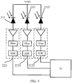
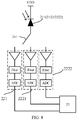
- Logical diagrams are illustrated as FIGS. 4 and 5 .
- the fingerprint sensor 211 may be reused as the red light sensor 2121 and/or the green light sensor 2122 as described above.
- the light sensing unit 21 may include only the fingerprint sensor 211, and the signal processing unit may include both the fingerprint signal processing circuitry 221 and the red light signal processing circuitry 2221, both the fingerprint signal processing circuitry 221 and the green light signal processing circuitry 2222, or all of the fingerprint signal processing circuitry 221, the red light signal processing circuitry 2221 and the green light signal processing circuitry 2222.
- the optical fingerprint module may further include a first circuit gating switch 241. The logical diagrams of the above three cases are illustrated as FIGS. 6 to 8 .
- the fingerprint sensor 211 is configured to collect light signals for the fingerprint recognition and collect red light for the health testing.
- the fingerprint signal processing circuitry 221 is connected to the control unit 23 and is configured to process the light signals collected by the fingerprint sensor 211 to obtain the fingerprint signal.
- the red light signal processing circuitry 2221 is connected to the control unit 23 and is configured to process the red light collected by the fingerprint sensor 211 to obtain the red light signal.
- One terminal of the first circuit gating switch 241 is connected to the fingerprint sensor 211, and the other terminal is connected to either the fingerprint signal processing circuitry 221 or the red light signal processing circuitry 2221.
- the control unit 23 is configured to generate the fingerprint information for the fingerprint recognition based on the fingerprint signal output from the fingerprint signal processing circuitry 221 and generate the health parameter information generated based on the red light signal output by the red light signal processing circuitry 2221.
- the fingerprint sensor 211 is configured to collect light signals for the fingerprint recognition and collect green light for the health testing.
- the fingerprint signal processing circuitry 221 is connected to the control unit 23 and is configured to process the light signals collected by the fingerprint sensor 211 to obtain the fingerprint signal.
- the green light signal processing circuitry 2222 is connected to the control unit 23 and is configured to process the green light collected by the fingerprint sensor 211 to obtain the green light signal.
- One terminal of the first circuit gating switch 241 is connected to the fingerprint sensor 211, and the other terminal is connected to either the fingerprint signal processing circuitry 221 or the green light signal processing circuitry 2222.
- the control unit 23 is configured to generate the fingerprint information for the fingerprint recognition based on the fingerprint signal output from the fingerprint signal processing circuitry 221 and generate the health parameter information based on the green light signal output by the green light signal processing circuitry 2222.
- the fingerprint sensor 211 is configured to collect light signals for the fingerprint recognition, the red light and the green light for the health testing.
- the fingerprint signal processing circuitry 221 is connected to the control unit 23 and is configured to process the light signals collected by the fingerprint sensor 211 to obtain the fingerprint signal.
- the red light signal processing circuitry 2221 is connected to the control unit 23 and is configured to process the red light collected by the fingerprint sensor 211 to obtain the red light signal.
- the green light signal processing circuitry 2222 is connected to the control unit 23 and is configured to process the green light collected by the fingerprint sensor 211 to obtain the green light signal.
- the control unit 23 is configured to generate fingerprint information for the fingerprint recognition based on the fingerprint signal output by the fingerprint signal processing circuitry 221, generate the health parameter information based on the red light signal output by the red light signal processing circuitry 2221, and generate the health parameter information based on the green light signal output by the green light signal processing circuitry 2222.
- the fingerprint sensor is reused as (or also functioned as) a red light sensor and/or a green light sensor. Therefore, there is no need to additionally arrange a health sensor in the electronic device having the optical fingerprint module, thereby solving a problem that the ratio of the area of the screen to the area of the front panel of the electronic device is reduced by separately arranging the health sensor, reducing the number of sensors to be deployed, and reducing hardware costs.
- the light sensing unit 21 may include a first fingerprint sensor 2111 and a second fingerprint sensor 2112.
- the signal processing unit 22 may include a first fingerprint signal processing circuitry 2211, a red light signal processing circuitry 2221, a second fingerprint signal processing circuitry 2212 and a green light signal processing circuitry 2222.
- a second circuit gating switch 242 and a third circuit gating switch 243 may be also included. Details are illustrated in FIG. 9 .
- the first fingerprint sensor 2111 is configured to collect light signals for the fingerprint recognition and the red light for the health testing.
- the second fingerprint sensor 2112 is configured to collect light signals for the fingerprint recognition and the green light for the health testing.
- the first fingerprint signal processing circuitry 2211 is connected to the control unit 23 and is configured to process the light signals collected by the first fingerprint sensor 2111 to obtain the first fingerprint signal.
- the red light signal processing circuitry 2221 is connected to the control unit 23 and is configured to process the red light collected by the first fingerprint sensor 2111 to obtain the red light signal.
- the second fingerprint signal processing circuitry 2212 is connected to the control unit 23 and is configured to process the light signals collected by the second fingerprint sensor 2112 to obtain the second fingerprint signal.
- the green light signal processing circuitry 2222 is connected to the control unit 23 and is configured to process the green light collected by the second fingerprint sensor 2112 to obtain the green light signal.
- One terminal (or end) of the second circuit gating switch 242 is connected to the first fingerprint sensor 2111, and the other end is connected to either the first fingerprint signal processing circuitry 2211 or the red light signal processing circuitry 2221.
- One terminal of the third circuit gating switch 243 is connected to the second fingerprint sensor 2112, and the other terminal is connected to either the second fingerprint signal processing circuitry 2212 or the green light signal processing circuitry 2222.
- the control unit 23 is configured to generate fingerprint information for the fingerprint recognition based on the first fingerprint signal output by the first fingerprint signal processing circuitry 2211 and/or the second fingerprint signal output by the second fingerprint signal processing circuitry 2212, generate the health parameter information based on the red light signal output by the red light signal processing circuitry 2221, and generate the health parameter information based on the green light signal output by the green light signal processing circuitry 2222.
- two different sensors are reused respectively as the red light sensor and the green light sensor. Compared with the embodiments as mentioned above, one fingerprint sensor in embodiments of FIG. 9 is reused as a sensor for processing a light signal of a single color, thereby reducing the color types of light signals to be collected by a single sensor and accordingly reducing the burden of the fingerprint sensor.
- the red light signal and the green light signal may be separately obtained for the health testing, and the red light signal or the green light signal which has a higher stability can be further used as the health signal to generate the health parameter information.
- the red light and the green light may be interfered differently in different environments, which will affect the results of the health testing. It can be seen that with the method, selection may be performed on the red light signal and the green light signal to determine the a signal that is less interfered for the health testing, thereby improving the accuracy of the health testing.
- the health testing may be made usually by sending a beam of light to the human body and evaluating the health of the human body based on changes in the returned beam of light. Therefore, the optical fingerprint module may also include a health signal emitting end.
- the optical fingerprint module may include a red light emitting end and/or a green light emitting end. The red light emitting end is configured to emit the red light for the health testing, and the green light emitting end is configured to emit the green light for the health testing.
- the light signals collected by the present disclosure for the health testing may be monochromatic light, such as the red light and the green light as described above, and the health sensor may be a red light sensor or a green light sensor accordingly.
- the light signals can also be infrared light, and the health sensor can be an infrared sensor correspondingly.
- the health sensor is an infrared sensor, since the fingerprint sensor is configured to collect visible light, the fingerprint sensor cannot be reused as a health sensor.
- the health parameter information obtained by the optical fingerprint module of the present disclosure may include any of the following: heart rate, blood oxygen and blood pressure. Certainly, the above is only an example and illustrative. It should be understood that any parameter that can reflect the state of health can be used as the health parameter information of the present disclosure.
- the specific health parameter information obtained is related to the processing method of the health signal, which is not limited in the present disclosure.
- the control unit in the present disclosure may be an MCU (Microcontroller Unit), a DSP (digital signal processor), or a CPU (central processing unit).
- MCU Microcontroller Unit
- DSP digital signal processor
- CPU central processing unit
- the optical fingerprint module has both the health testing function and the fingerprint recognition function. Therefore, when this optical fingerprint module is integrated to an electronic device, there is no need to arrange a separate health sensor, thereby solving the problem existing in the related arts that the ratio of the area of the screen to the area of the front panel of the electronic device is reduced or the mechanical strength of the backplane of the electronic device is reduced by separately arranging the health sensor.
- the space of the main circuit board of electronic device that is occupied by the health sensor may be reduced, such that developers can flexibly arrange various components at desired positions on the main circuit board, and development difficulty may be reduced.
- the health sensor according to the present disclosure can include both the red light sensor and the green light sensor.
- a signal that is less interfered may be selected from the signal collected by the red light sensor and the signal collected by the green light sensor can be selected to generate the health parameter information, thereby improving the accuracy of the health testing.
- FIG. 10 is a schematic diagram illustrating a touch and display module according to some embodiments of the present disclosure.
- the touch and display module includes a glass cover layer 101, a touch layer 102, a display layer 103, and a health testing and fingerprint recognition layer 104.
- a sensing side of the touch layer 102 faces towards the glass cover layer 101.
- a light-emitting side of the display layer 103 faces towards a non-sensing side of the touch layer 102.
- the health testing and fingerprint recognition layer 104 includes the optical fingerprint module as described above, and a light-incoming side of the health testing and fingerprint recognition layer 104 faces towards the non-light-emitting side of the display layer 103.
- the glass cover layer 101 may be made of a transparent glass material for protecting the touch and display module.
- the sensing side of the touch layer 102 can generate a touch signal based on a user's touch position.
- the method for generating the touch signal can be a sensing method of a capacitive screen or a sensing method of a resistive screen, which is not limited herein.
- the display layer 103 is also called a light-emitting layer and can display a corresponding image based on a control signal.
- the light sensing unit of the optical fingerprint module may be arranged on the light-incoming side of the health testing and fingerprint recognition layer 104 to collect the light signals.
- the health testing and fingerprint recognition layer of the touch and display module includes the optical fingerprint module described above. It can be seen that the processes of the health testing and fingerprint recognition are both performed by the touch and display module, such that the electronic device using the touch and display module does not need to arrange a separate health sensor. Compared to the electronic device that has a separately arranged health sensor outside the touch and display module, the mechanical strength of the backplane of the electronic device may be not affected and the ratio of the area of the screen to the area of the front panel may be higher in the present disclosure.
- FIG. 11 is a schematic diagram illustrating an electronic device according to some embodiments of the present disclosure.
- the electronic device includes: a touch and display module 111 and the optical fingerprint module 112 as described above.
- the assembly position of the optical fingerprint module corresponds to the fingerprint recognition region 113 formed on the touch and display module; or the electronic device includes the touch and display module as illustrated in FIG. 10 .
- the user can touch the fingerprint recognition region 113 with a finger to trigger the electronic device to perform the fingerprint recognition operation.
- the fingerprint sensors can be used as the health sensor of the optical fingerprint module.
- the fingerprint sensor may be reused as a health sensor, , thereby reducing the number of sensors to be deployed.
- a health sensor can be arranged near at least one fingerprint sensor. In this case, compared to the layout in the related arts, the position of the health sensor moves from outside the touch and display module to the fingerprint recognition region of the touch and display module, thereby avoiding separately arranging a health sensor.
- the optical fingerprint module described above is assembled in the fingerprint recognition region. It can be seen that both the fingerprint sensor and the health sensor are arranged in the touch and display module, which solves the problem that the ratio of the area of the screen to the area of the front panel of the electronic device is reduced and the mechanical strength of the backplane of the electronic device is reduced due to the separately arranged health sensor.
- FIG. 12 is a flowchart illustrating a method for processing a signal according to some embodiments of the present disclosure. The method is applied to an electronic device including the optical fingerprint module as described above, or an electronic device as described above. The method may include the following.
- a predefined health testing condition and a predefined fingerprint recognition condition are determined.
- the optical fingerprint module after the light signals are collected by the light sensing unit in the optical fingerprint module, it can be determined whether to perform the health monitoring or the fingerprint recognition to collect corresponding light signals by the light sensing unit, based on the predefined health testing condition and the predefined fingerprint recognition condition.
- the light signals for the health testing collected by the light sensing unit is input to the signal processing unit in the optical fingerprint module, to generate the health parameter information based on the health signal output by the signal processing unit.
- the light signals for the fingerprint recognition collected by the light sensing unit is input to the signal processing unit in the optical fingerprint module, to generate the fingerprint information for the fingerprint recognition based on the fingerprint signal output by the signal processing unit.
- the fingerprint recognition is usually performed to perform operations such as unlocking and payment. Therefore, it can be determined whether the fingerprint recognition is required by determining whether the fingerprint recognition region formed by the touch and display module of the electronic device detects a touch event or not. In this case, when a touch event that occurs in the fingerprint recognition region is detected, it is determined that the fingerprint recognition condition is met.
- the aforementioned fingerprint recognition condition that is, in the case that the touch event occurring in the fingerprint recognition region is detected, it can be further determined whether a pressing force corresponding to the touch event is not less than a preset pressure threshold. In the case that the pressing force is not less than the preset pressure threshold, it is determined that the fingerprint recognition condition is satisfied.
- a function of realizing the health testing may be set as a preset function and it may be determined whether the preset function of the electronic device is in an on state during the operation of the electronic device. In response to detecting that the preset function is in the on state, it is determined that the health detection condition is satisfied.
- the light used for health detection is collected, different software processing methods are adopted for the light to obtain different health parameter information.
- the heart rate, blood oxygen, blood pressure and other parameters of the subject can be obtained by processing and analyzing the collected light.
- the light signals used to generate the health signal and the fingerprint signal are collected by the sensor arranged in the touch and display module, thereby solving the problem existing in the related arts that the ratio of the area of the screen to the area of the front panel of the electronic device is reduced and the mechanical strength of the backplane of the electronic device is affected by separately arranging the health sensor.
- the fingerprint recognition region by determining whether the fingerprint recognition region is touched, it may be determined whether the fingerprint recognition is currently required. It should be understood that touching the fingerprint recognition region by the user means that there are unlocking and payment requirements, and fingerprint recognition is required.
- whether the preset function is in the on state is also used as the health detection condition. It should be understood that when the user activates the preset function for realizing the health testing, it is obviously that there is a need for the health testing.
- the technical solutions according to the present disclosure can perform the health testing or the fingerprint recognition based on the actual needs of the user, thereby improving user experience.
- FIG. 13 is a flowchart illustrating a method for health testing according to some embodiments of the present disclosure.
- the method is applicable to an electronic device including the optical fingerprint model having both a red light collecting function and a green light collecting function as described above.
- the method can include the following.
- the red light for the health testing is collected by the light sensing unit in the optical fingerprint module, and the red light collected by the light sensing unit is inputted into the red light signal processing circuitry in the optical fingerprint module, such that the red light signal processing circuitry processes the red light to obtain the red light signal.
- the green light for the health testing is collected by the light sensing unit in the optical fingerprint module, and the green light collected by the light sensing unit is input into the green light signal processing circuitry in the optical fingerprint module, such that the green light signal processing circuitry processes the green light to obtain the green light signal.
- the light since the light may be interfered by many factors during the propagation process, the light will continuously change during the propagation process.
- the stabilities of different lights are different in different environments. For example, when the human body is sweating, the sweat is easier to absorb the green light than the red light. As a result, the red light is more stable when the human body is sweating, and health testing is more accurate based on the red light.
- the red light and the green light are collected by the optical fingerprint module, and the stability of the red light signal obtained by processing the red light is compared with the stability of the green light signal obtained by processing the green light to select the a signal having the higher stability as the health signal to generate the health parameter information.
- the health testing based on the green light may be more accurate. Therefore, in some embodiments, if the stability of the red light signal obtained by processing the red light is close to that of the green light signal obtained by processing the green light, the health testing is performed based on the green light signal obtained by processing the green light.
- the optical fingerprint module provided in the electronic device requires the functions of collecting the red light and the green light. Therefore, the optical fingerprint module according to the embodiments may be an optical fingerprint module being capable of collecting the red light and the green light as described above.
- the stability of the red light signal is compared with the stability of the green light signal by the control unit in the optical fingerprint module, such that the control unit may generate the health parameter information based on a signal having the higher stability and selected from the red light signal and the green light signal.
- the health testing is performed with the red light and the green light. It is usually necessary to configure corresponding light emitting ends, such as the red light emitting end in the electronic device and configured to emit the red light, and the green light emitting end in the electronic device and configured to emit the green light. Certainly, since the optical fingerprint module in the electronic device can emit light itself, the red light and/or green light used for the health testing can be emitted by the optical fingerprint module.
- the obtained health parameter information may include any of: heart rate, blood oxygen, and blood pressure.
- heart rate blood oxygen
- blood pressure any parameter that can reflect the state of health
- the specific health parameter information obtained is related to the method for processing the health signal, which is not limited in the present disclosure.
- the health parameter information may be generated based on the signal having the higher stability.
- the accuracy of health testing may be improved in the present disclosure by selecting the better one from the red light signal and the green light signal.
- the present disclosure also provides embodiments of a device for processing a signal.
- Fig. 14 is a block diagram illustrating a device for processing a signal according to some embodiments of the present disclosure. As illustrated in FIG. 14 , the device may include a determining unit 1401, a first generating unit 1402, and a second generating unit 1403.
- the determining unit 1401 is configured to determine a predefined health testing condition and a predefined fingerprint recognition condition.
- the first generating unit 1402 is configured to input the light signal for the health testing collected by the light sensing unit to the signal processing unit in the optical fingerprint module when the health testing condition is satisfied, and to generate the health parameter information based on the health signal output by the signal processing unit.
- the second generating unit 1403 is configured to input the light signal for the fingerprint recognition collected by the light sensing unit to the signal processing unit in the optical fingerprint module when the fingerprint recognition condition is satisfied, to generate the fingerprint information for the fingerprint recognition based on the fingerprint signal output by the signal processing unit.
- FIG. 15 is a block diagram illustrating another device for processing a signal processing device according to some embodiments of the present disclosure. On the basis of the foregoing embodiment illustrated in FIG. 14 , this embodiment further includes a judging unit 1404.
- the judging unit 1404 is configured to determine whether a touch event is detected in the fingerprint recognition region formed by the touch and display module of the electronic device.
- Meeting the fingerprint recognition condition includes detecting that the touch event occurs in the fingerprint recognition region.
- meeting the fingerprint recognition condition further includes: in the case of detecting that the touch event occurs in the fingerprint recognition region, determining that a pressing force corresponding to the touch event is not less than a preset pressure threshold.
- the judging unit 1404 is further configured to determine whether the preset function of the electronic device is in an on state.
- Meeting the health testing condition includes that the preset function is in the on state.
- the judging unit 1404 in the device embodiments illustrated in FIG. 15 may also be included in the device embodiment in FIG. 14 , which is not limited in the present disclosure.
- the present disclosure also provides embodiments of a device for acquiring a health signal.
- FIG. 16 is a block diagram illustrating a device for acquiring a health signal according to some embodiments of the present disclosure. As illustrated in FIG. 16 , the device may include a red light processing unit 1601, a green light processing unit 1602, and an information generating unit 1603.
- the red light processing unit 1601 is configured to collect the red light for the health testing by the light sensing unit in the optical fingerprint module; input the red light collected by the light sensing unit into the red light signal processing circuitry of the optical fingerprint module; and process the red light by the red light signal processing circuitry to obtain the red light signal.
- the green light processing unit 1602 is configured to collect the green light for the health testing by the light sensing unit in the optical fingerprint module; input the green light collected by the light sensing unit into the green light signal processing circuitry of the optical fingerprint module; and process the green light by the green light signal processing circuitry to obtain the green light signal.
- the information generating unit 1603 is configured to compare the stability of the red light signal and the stability of the green light signal by the control unit of the optical fingerprint module, and generate the health parameter information by the control unit based on a signal having the higher stability and selected from the red light signal and the green light signal.
- the red light and/or the green light are emitted by a touch and display module of the electronic device.
- the red light is emitted by the red light emitting end of the electronic device; and the green light is emitted by the green light emitting end of the electronic device.
- the health parameter information includes at least one of: value of heart rate, value of blood oxygen, and value of blood pressure.
- the relevant part can refer to the part of the description of the method embodiments.
- the device embodiments described above are merely illustrative.
- the units described as separate components may or may not be physically separated, and the components displayed as units may or may not be physical units, that is, they may be located in one place, or distributed to multiple network units.
- Some or all of the modules can be selected according to actual needs to achieve the objectives of the technical solutions of the present disclosure. Those of ordinary skill in the art can understand and implement it without creative work.
- the present disclosure also provides a device for processing a signal, including: a processor and a memory.
- the memory is configured to store instructions executable by the processor.
- the processor is configured to implement the method for processing a signal as described in any of the above embodiments.
- the method may include determining a predefined health testing condition and a predefined fingerprint recognition condition; when the health testing condition is met, inputting the light signal for the health testing collected by the light sensing unit to the signal processing unit of the optical fingerprint module described herein, and generating the health parameter information based on the health signal output by the signal processing unit; when the fingerprint recognition condition is met, inputting the light signal for the fingerprint recognition collected by the light sensing unit to the signal processing unit of the optical fingerprint module described above, and generating the fingerprint information for the fingerprint recognition based on the fingerprint signal output by the signal processing unit.
- the present disclosure also provides a device for acquiring a health signal including a processor and a memory.
- the memory is configured to store instructions executable by the processor.
- the processor is configured to implement the method for acquiring a health signal according to any one of the above-mentioned embodiments.
- the method may include: collecting red light for the health testing by a light sensing unit of the optical fingerprint module; inputting the red light collected by the light sensing unit into the aforementioned red light signal processing circuitry of the optical fingerprint module with the red light collection function and the green light collection function, and processing the red light by the red light signal processing circuity to obtain the red light signal; collecting green light for the health testing by the light sensing unit of the optical fingerprint module; inputting the green light collected by the light sensing unit into the green light signal processing circuitry in the optical fingerprint module with the red light collection function and the green light collection function described above, and processing the green light by the green light signal processing circuitry to obtain the green light signal; comparing by the control unit in the optical fingerprint module the stability of the red light signal and the stability of the green light signal, and generating the health parameter information by the control unit based on a signal selected from the red light signal and the green light signal and corresponding to the higher stability.
- the present disclosure also provides an electronic device including a memory and one or more programs.
- the one or more programs are stored in the memory and are configured such that the one or more processors execute instructions for implementing the method for processing a signal or the method for acquiring a health signal as described in any of the above embodiments.
- the method may include: determining a predefined health testing condition and a fingerprint recognition condition; in the case that the health testing condition is met, inputting the light signal for the health testing collected by the light sensing unit to the signal processing unit in the optical fingerprint module described above, to generate the health parameter information based on the health signal output by the signal processing unit; in the case that the fingerprint recognition condition is met, inputting the light signal for the fingerprint recognition collected by the light sensing unit into the signal processing unit of the optical fingerprint module described above, to generate the fingerprint information for the fingerprint recognition based on the fingerprint signal output by the signal processing unit.
- FIG. 17 is a block diagram illustrating a device 1700 for implementing a method for processing a signal according to some embodiments of the present disclosure.
- the device 1700 may be a mobile phone, a computer, a digital broadcasting terminal, a messaging device, a game console, a tablet device, a medical device, a fitness device, a personal digital assistant, etc.
- the device 1700 may include one or more of: a processing component 1702, a memory 1704, a power supply component 1706, a multimedia component 1708, an audio component 1710, an input/output (I/O) interface 1712, a sensor component 1714, and a communication component 1716.
- the processing component 1702 generally controls the overall operations of the device 1700, such as operations associated with display, calls, data communications, camera operations, and recording operations.
- the processing component 1702 may include one or more processors 1720 to execute instructions to complete all or part of the steps of the foregoing method.
- the processing component 1702 may include one or more modules to facilitate the interaction between the processing component 1702 and other components.
- the processing component 1702 may include a multimedia module to facilitate the interaction between the multimedia component 1708 and the processing component 1702.
- the memory 1704 is configured to store various types of data to support operations of the device 1700. Examples of such data include instructions for any application or method operating on the device 1700, contact data, phone book data, messages, pictures, videos, etc.
- the memory 1704 can be implemented by any type of volatile or non-volatile storage devices or the combination thereof, such as static random access memory (SRAM), electrically erasable programmable read-only memory (EEPROM), erasable Programmable read-only memory (EPROM), programmable read-only memory (PROM), read-only memory (ROM), magnetic memory, flash memory, magnetic disk or optical disk.
- SRAM static random access memory
- EEPROM electrically erasable programmable read-only memory
- EPROM erasable Programmable read-only memory
- PROM programmable read-only memory
- ROM read-only memory
- magnetic memory flash memory
- flash memory magnetic disk or optical disk.
- the power supply component 1706 provides power to various components of the device 1700.
- the power supply component 1706 may include a power management system, one or more power supplies, and other components associated with the generation, management, and distribution of power for the device 1700.
- the multimedia component 1708 includes a screen that provides an output interface between the device 1700 and the user.
- the screen may include a liquid crystal display (LCD) and a touch panel (TP). If the screen includes a touch panel, the screen may be implemented as a touch screen to receive input signals from the user.
- the touch panel includes one or more touch sensors to sense touch, sliding, and gestures on the touch panel. The touch sensor may not only sense the boundary of a touch or a slide action, but also detect the duration and pressure related to the touch or the slide operation.
- the multimedia component 1708 includes a front camera and/or a rear camera. When the device 1700 is in an operation mode, such as a shooting mode or a video recording mode, the front camera and/or the rear camera can receive external multimedia data. Each front camera and rear camera can be a fixed optical lens system or have focal length and optical zoom capabilities.
- the audio component 1710 is configured to output and/or input audio signals.
- the audio component 1710 includes a microphone (MIC).
- the microphone is configured to receive external audio signals.
- the received audio signal may be further stored in the memory 1704 or transmitted via the communication component 1716.
- the audio component 1710 further includes a speaker for outputting audio signals.
- the I/O interface 1712 provides an interface between the processing component 1702 and a peripheral interface module.
- the peripheral interface module may be a keyboard, a click wheel, a button, and the like. These buttons may include but are not limited to home button, volume button, start button, and lock button.
- the sensor component 1714 includes one or more sensors for providing the device 1700 with various aspects of status assessment.
- the sensor component 1714 can detect the opening/closing status of the device 1700 and the relative positioning of components.
- the component is the display and the keypad of the device 1700.
- the sensor component 1714 can also detect the position change of the device 1700 or a component of the device 1700, the presence or absence of contact between the user and the device 1700, the orientation or acceleration/deceleration of the device 1700, and the temperature change of the device 1700.
- the sensor assembly 1714 may include a proximity sensor configured to detect the presence of nearby objects when there is no physical contact.
- the sensor component 1714 may also include a light sensor, such as a CMOS or CCD image sensor, for use in imaging applications.
- the sensor component 1714 may also include an acceleration sensor, a gyroscope sensor, a magnetic sensor, a pressure sensor or a temperature sensor.
- the communication component 1716 is configured to facilitate wired or wireless communication between the device 1700 and other devices.
- the device 1700 can access a wireless network based on a communication standard, such as WiFi, 2G or 3G, 4G LTE, 5G NR (new radio), or a combination thereof.
- the communication component 1716 receives a broadcast signal or broadcast-related information from an external broadcast management system via a broadcast channel.
- the communication component 1716 further includes a near field communication (NFC) module to facilitate short-range communication.
- the NFC module can be implemented based on radio frequency identification (RFID) technology, infrared data association (IrDA) technology, ultra-wideband (UWB) technology, Bluetooth (BT) technology and other technologies.
- RFID radio frequency identification
- IrDA infrared data association
- UWB ultra-wideband
- Bluetooth Bluetooth
- the apparatus 1700 may be implemented by one or more application specific integrated circuits (ASIC), digital signal processors (DSP), digital signal processing equipment (DSPD), programmable logic devices (PLD), field programmable Implemented by a gate array (FPGA), controller, microcontroller, microprocessor, or other electronic components, used to perform the above methods.
- ASIC application specific integrated circuits
- DSP digital signal processors
- DSPD digital signal processing equipment
- PLD programmable logic devices
- FPGA field programmable Implemented by a gate array
- controller microcontroller, microprocessor, or other electronic components, used to perform the above methods.
- non-transitory computer-readable storage medium including instructions, such as a memory 1704 including instructions, which can be executed by the processor 1720 of the device 1700 to implement the foregoing method.
- the non-transitory computer-readable storage medium may be ROM, random access memory (RAM), CD-ROM, magnetic tape, floppy disk, optical data storage device, etc.
Landscapes
- Health & Medical Sciences (AREA)
- Engineering & Computer Science (AREA)
- Life Sciences & Earth Sciences (AREA)
- Physics & Mathematics (AREA)
- Public Health (AREA)
- Medical Informatics (AREA)
- General Health & Medical Sciences (AREA)
- Biomedical Technology (AREA)
- Pathology (AREA)
- Molecular Biology (AREA)
- Biophysics (AREA)
- Heart & Thoracic Surgery (AREA)
- Veterinary Medicine (AREA)
- Surgery (AREA)
- Animal Behavior & Ethology (AREA)
- Theoretical Computer Science (AREA)
- Cardiology (AREA)
- General Engineering & Computer Science (AREA)
- General Physics & Mathematics (AREA)
- Human Computer Interaction (AREA)
- Physiology (AREA)
- Multimedia (AREA)
- Optics & Photonics (AREA)
- Signal Processing (AREA)
- Spectroscopy & Molecular Physics (AREA)
- Epidemiology (AREA)
- Primary Health Care (AREA)
- Databases & Information Systems (AREA)
- Power Engineering (AREA)
- Data Mining & Analysis (AREA)
- Artificial Intelligence (AREA)
- Computer Vision & Pattern Recognition (AREA)
- Psychiatry (AREA)
- Measurement Of The Respiration, Hearing Ability, Form, And Blood Characteristics Of Living Organisms (AREA)
- Image Input (AREA)
Applications Claiming Priority (1)
| Application Number | Priority Date | Filing Date | Title |
|---|---|---|---|
| CN202010556453.8A CN113807153A (zh) | 2020-06-17 | 2020-06-17 | 光学指纹模组和信号处理方法 |
Publications (2)
| Publication Number | Publication Date |
|---|---|
| EP3926527A2 true EP3926527A2 (de) | 2021-12-22 |
| EP3926527A3 EP3926527A3 (de) | 2022-03-09 |
Family
ID=75252341
Family Applications (1)
| Application Number | Title | Priority Date | Filing Date |
|---|---|---|---|
| EP21165093.2A Pending EP3926527A3 (de) | 2020-06-17 | 2021-03-26 | Optisches fingerabdruckmodul und signalverarbeitungsverfahren |
Country Status (3)
| Country | Link |
|---|---|
| US (1) | US11941908B2 (de) |
| EP (1) | EP3926527A3 (de) |
| CN (1) | CN113807153A (de) |
Family Cites Families (12)
| Publication number | Priority date | Publication date | Assignee | Title |
|---|---|---|---|---|
| US8605961B2 (en) * | 2009-03-30 | 2013-12-10 | Motorola Mobility Llc | Method and apparatus for determining a physiological parameter using a fingerprint sensor on a portable electronic device |
| US10610159B2 (en) * | 2012-10-07 | 2020-04-07 | Rhythm Diagnostic Systems, Inc. | Health monitoring systems and methods |
| EP3278272B1 (de) * | 2015-06-18 | 2020-12-09 | Shenzhen Goodix Technology Co., Ltd. | Multifunktionsfingerabdrucksensor mit optischer abtastfähigkeit |
| US10268884B2 (en) | 2016-01-29 | 2019-04-23 | Synaptics Incorporated | Optical fingerprint sensor under a display |
| EP3485342B1 (de) * | 2016-07-18 | 2021-02-17 | Shenzhen Goodix Technology Co., Ltd. | Optischer fingerabdrucksensor mit kraftmessfähigkeit |
| KR102681121B1 (ko) * | 2016-11-15 | 2024-07-02 | 삼성전자주식회사 | 생체 성분 측정 장치 및 방법 |
| CN206563971U (zh) * | 2017-01-21 | 2017-10-17 | 苏州易指通智能科技有限公司 | 具有健康信息检测功能的指纹识别装置 |
| CN107203938A (zh) * | 2017-05-02 | 2017-09-26 | 优品财富管理股份有限公司 | 一种基于心率检测的股民投资指导系统及方法 |
| CN109567773A (zh) * | 2018-11-29 | 2019-04-05 | 努比亚技术有限公司 | 基于指纹的血压测量方法、终端及计算机可读存储介质 |
| CN109620195B (zh) * | 2019-01-08 | 2023-11-17 | 研和智能科技(杭州)有限公司 | 基于可穿戴设备的多波长信号融合心率检测方法及系统 |
| CN110604558A (zh) * | 2019-09-23 | 2019-12-24 | Oppo广东移动通信有限公司 | 移动终端及脉搏检测方法 |
| CN110742596A (zh) * | 2019-10-17 | 2020-02-04 | Oppo广东移动通信有限公司 | 用于拍照及生物信息测量的电子设备 |
-
2020
- 2020-06-17 CN CN202010556453.8A patent/CN113807153A/zh active Pending
-
2021
- 2021-03-18 US US17/205,342 patent/US11941908B2/en active Active
- 2021-03-26 EP EP21165093.2A patent/EP3926527A3/de active Pending
Also Published As
| Publication number | Publication date |
|---|---|
| EP3926527A3 (de) | 2022-03-09 |
| US11941908B2 (en) | 2024-03-26 |
| US20210397807A1 (en) | 2021-12-23 |
| CN113807153A (zh) | 2021-12-17 |
Similar Documents
| Publication | Publication Date | Title |
|---|---|---|
| EP3046017B1 (de) | Freigabeverfahren, -vorrichtung und -endgerät | |
| RU2643460C2 (ru) | Способ и устройство для реализации сенсорной кнопки и идентификации отпечатка пальца, а также терминальное устройство | |
| EP3046042B1 (de) | Vorrichtung zur implementierung von home tasten und fingerabdruckidentifizierung durch gemensaimen sensor | |
| US10025393B2 (en) | Button operation processing method in single-hand mode | |
| EP3525075B1 (de) | Verfahren zur beleuchtung des bildschirms eines doppelbildschirmendgeräts sowie endgerät | |
| US9922227B2 (en) | Apparatus and method for implementing touch control and fingerprint identification | |
| EP3901824A1 (de) | Verfahren und vorrichtung zur realisierung eines berührungsknopfs und fingerabdruckerkennung sowie endgerätevorrichtung | |
| EP3444752B1 (de) | Fingerabdruckerkennungsverfahren | |
| US20180088697A1 (en) | Terminal, method, apparatus and electronic device for identifying touch | |
| US10102410B2 (en) | Terminal device with function of fingerprint identification | |
| EP3644586A1 (de) | Verfahren zur verarbeitung einer gesperrten bildschirmschnittstelle und endgerät | |
| US20160195992A1 (en) | Mobile terminal and method for processing signals generated from touching virtual keys | |
| JP2018508008A (ja) | 圧力検出方法、装置、プログラム、及び記録媒体 | |
| JP7127105B2 (ja) | 光学指紋モジュールおよび信号処理方法 | |
| CN107168566B (zh) | 操作模式控制方法、装置及终端电子设备 | |
| KR101918991B1 (ko) | 헬스 케어 기능을 구비하는 이동 단말기 및 그것의 제어 방법 | |
| US11941908B2 (en) | Optical fingerprint module and signal processing method | |
| CN106293184A (zh) | 可侧边触控的终端及其触控方法 | |
| CN112445363A (zh) | 电子设备、电子设备的控制方法及装置、存储介质 | |
| CN109409168A (zh) | 检测指纹的处理方法及装置 | |
| CN113887267A (zh) | 光学指纹模组和信号处理方法 | |
| CN113739912B (zh) | 光学信号检测模组和光强检测方法 | |
| CN107340899B (zh) | 一种移动终端、移动终端控制方法及装置 | |
| CN111103997A (zh) | 防误触方法、设备及可读存储介质 | |
| CN113743166A (zh) | 光学指纹模组和信号处理方法 |
Legal Events
| Date | Code | Title | Description |
|---|---|---|---|
| PUAI | Public reference made under article 153(3) epc to a published international application that has entered the european phase |
Free format text: ORIGINAL CODE: 0009012 |
|
| STAA | Information on the status of an ep patent application or granted ep patent |
Free format text: STATUS: THE APPLICATION HAS BEEN PUBLISHED |
|
| AK | Designated contracting states |
Kind code of ref document: A2 Designated state(s): AL AT BE BG CH CY CZ DE DK EE ES FI FR GB GR HR HU IE IS IT LI LT LU LV MC MK MT NL NO PL PT RO RS SE SI SK SM TR |
|
| PUAL | Search report despatched |
Free format text: ORIGINAL CODE: 0009013 |
|
| AK | Designated contracting states |
Kind code of ref document: A3 Designated state(s): AL AT BE BG CH CY CZ DE DK EE ES FI FR GB GR HR HU IE IS IT LI LT LU LV MC MK MT NL NO PL PT RO RS SE SI SK SM TR |
|
| RIC1 | Information provided on ipc code assigned before grant |
Ipc: A61B 5/00 20060101ALI20220201BHEP Ipc: G06K 9/00 20060101AFI20220201BHEP |
|
| STAA | Information on the status of an ep patent application or granted ep patent |
Free format text: STATUS: REQUEST FOR EXAMINATION WAS MADE |
|
| 17P | Request for examination filed |
Effective date: 20220907 |
|
| RBV | Designated contracting states (corrected) |
Designated state(s): AL AT BE BG CH CY CZ DE DK EE ES FI FR GB GR HR HU IE IS IT LI LT LU LV MC MK MT NL NO PL PT RO RS SE SI SK SM TR |
|
| STAA | Information on the status of an ep patent application or granted ep patent |
Free format text: STATUS: EXAMINATION IS IN PROGRESS |
|
| 17Q | First examination report despatched |
Effective date: 20240215 |
|
| REG | Reference to a national code |
Ref country code: DE Ref legal event code: R079 Free format text: PREVIOUS MAIN CLASS: G06K0009000000 Ipc: G06V0040130000 |
|
| GRAP | Despatch of communication of intention to grant a patent |
Free format text: ORIGINAL CODE: EPIDOSNIGR1 |
|
| STAA | Information on the status of an ep patent application or granted ep patent |
Free format text: STATUS: GRANT OF PATENT IS INTENDED |