EP3926380A1 - Mirror mount for a head-up display - Google Patents
Mirror mount for a head-up display Download PDFInfo
- Publication number
- EP3926380A1 EP3926380A1 EP20181029.8A EP20181029A EP3926380A1 EP 3926380 A1 EP3926380 A1 EP 3926380A1 EP 20181029 A EP20181029 A EP 20181029A EP 3926380 A1 EP3926380 A1 EP 3926380A1
- Authority
- EP
- European Patent Office
- Prior art keywords
- mirror mount
- housing
- spring
- bushing
- mirror
- Prior art date
- Legal status (The legal status is an assumption and is not a legal conclusion. Google has not performed a legal analysis and makes no representation as to the accuracy of the status listed.)
- Granted
Links
Images


Classifications
-
- G—PHYSICS
- G02—OPTICS
- G02B—OPTICAL ELEMENTS, SYSTEMS OR APPARATUS
- G02B7/00—Mountings, adjusting means, or light-tight connections, for optical elements
- G02B7/18—Mountings, adjusting means, or light-tight connections, for optical elements for prisms; for mirrors
- G02B7/182—Mountings, adjusting means, or light-tight connections, for optical elements for prisms; for mirrors for mirrors
- G02B7/1821—Mountings, adjusting means, or light-tight connections, for optical elements for prisms; for mirrors for mirrors for rotating or oscillating mirrors
-
- G—PHYSICS
- G02—OPTICS
- G02B—OPTICAL ELEMENTS, SYSTEMS OR APPARATUS
- G02B27/00—Optical systems or apparatus not provided for by any of the groups G02B1/00 - G02B26/00, G02B30/00
- G02B27/01—Head-up displays
- G02B27/0149—Head-up displays characterised by mechanical features
-
- G—PHYSICS
- G02—OPTICS
- G02B—OPTICAL ELEMENTS, SYSTEMS OR APPARATUS
- G02B27/00—Optical systems or apparatus not provided for by any of the groups G02B1/00 - G02B26/00, G02B30/00
- G02B27/64—Imaging systems using optical elements for stabilisation of the lateral and angular position of the image
- G02B27/646—Imaging systems using optical elements for stabilisation of the lateral and angular position of the image compensating for small deviations, e.g. due to vibration or shake
-
- G—PHYSICS
- G02—OPTICS
- G02B—OPTICAL ELEMENTS, SYSTEMS OR APPARATUS
- G02B7/00—Mountings, adjusting means, or light-tight connections, for optical elements
- G02B7/18—Mountings, adjusting means, or light-tight connections, for optical elements for prisms; for mirrors
- G02B7/182—Mountings, adjusting means, or light-tight connections, for optical elements for prisms; for mirrors for mirrors
- G02B7/1822—Mountings, adjusting means, or light-tight connections, for optical elements for prisms; for mirrors for mirrors comprising means for aligning the optical axis
Definitions
- a head-up display or HUD is a transparent display panel that presents information to a user without requiring users to look away from a preferred viewing direction.
- the origin of the name stems from a pilot being able to view information with the head positioned "up" and looking forward, instead of angled down looking at lower instruments.
- a mirror mount for a Head-Up Display comprising two substantially coaxial bores for being pivotably suspended in a housing about an axis by means of bearing pins, wherein each bore of the mirror mount is provided with a bushing in the respective bore, wherein the mirror mount comprises two radially acting springs for spring-loading each bushing against the mirror mount in a radial direction and an axially acting spring for spring-loading at least one of the bearing pins with respect to the mirror mount in an axial direction.
- the axially acting spring is a compression spring and is arranged within one of the bores to spring-load the bearing pin with respect to the mirror mount in the axial direction.
- the axially acting spring using a compression spring has shown to be preferable due to an easier mounting of the mirror mount within the housing. The axial spring cancels a possible gap in axial direction and pushes the mirror against the axial reference plane.
- At least one of the bushings has a slit and two joints to achieve a flexibility in radial directions.
- the slit and joints allow a flexing of the bearing by the spring to allow a three-point contact to the bearing pin in the mounting positon of the mirror mount in any tolerance situation.
- the bearing pin can be efficiently supported by the bushing, allowing a smooth pivoting movement of the mirror mount about the bearing pins.
- Figures 4 to 6 show the bushing 10 in detail.
- the bushing 10 is configured to support the respective bearing pin 6 on three contact points 19.
- the bushing 10 can have three inner surfaces that are aligned with respective angles towards each other. Alternatively, more than three contact points 19 or a smooth inner surface could be utilised too.
Landscapes
- Physics & Mathematics (AREA)
- General Physics & Mathematics (AREA)
- Optics & Photonics (AREA)
- Rear-View Mirror Devices That Are Mounted On The Exterior Of The Vehicle (AREA)
- Instrument Panels (AREA)
Abstract
Description
- The present invention relates to a mirror mount for a Head-Up Display, the mirror mount comprising two substantially coaxial bores for being pivotably suspended in a housing about an axis by means of bearing pins.
- A head-up display or HUD is a transparent display panel that presents information to a user without requiring users to look away from a preferred viewing direction. The origin of the name stems from a pilot being able to view information with the head positioned "up" and looking forward, instead of angled down looking at lower instruments. Although they were initially developed for military aviation, HUD systems are nowadays used in commercial aircraft, automobiles, and other applications.
- For example, a driver can view traffic and the road in front of the vehicle through the windshield of the vehicle while at the same time a projector projects information onto the windshield. Such a HUD system typically comprises a video data source such as a computer, a projector, and a mirror for deflecting the output of the projector onto the windshield.
- Mirror positioning mechanisms require careful consideration to ensure the performance in all kinds of environmental conditions such as changing humidity and a wide range of temperatures especially within a dashboard of a car. A key design consideration relates to vibration. A mobile HUD system must have a high resistance to vibration in order to provide a stable image for the user. Failure to control vibration associated with the mirror in particular can result in a display that is irritating for the viewer and unpleasant to use over extended periods. Accordingly, a mirror and its respective mirror mount in a HUD system should have a high stability and a high natural frequency.
- Thus the mirror needs to be positioned very rigid in the operating position to prevent vibration and reduced image quality. Therefore, a mirror holder and the connecting mount on the car body have to be very stiff.
- To achieve this, the mirror itself is usually mounted on a mirror mount, which is in turn mounted in a housing in such a way that it can pivot about a mirror axis. For mounting the mirror mount in the housing, usually the housing comprises two holes, within which the mirror mount is suspended. However, due to the size of the housing, the holes in the housing and the corresponding bores in the mirror mount cannot be manufactured at the same time, which can lead to alignment errors. This results in unwanted tensions in the mirror mount, causing the mounting of the mirror to be too tight. Due to the small rotation angles, so-called stick-slip effects can occur, which further complicates an exact calibration. On the other hand enlarging the bores to allow easy rotation would lead to backlash, which would cause an inaccurate positioning and allows movement under vibration, leading to an unstable, blurry picture.
- The aim of the invention is thus to achieve a mirror system for a Head-Up Display that overcomes the above-mentioned drawbacks.
- This aim is achieved by a mirror mount for a Head-Up Display, the mirror mount comprising two substantially coaxial bores for being pivotably suspended in a housing about an axis by means of bearing pins, wherein each bore of the mirror mount is provided with a bushing in the respective bore, wherein the mirror mount comprises two radially acting springs for spring-loading each bushing against the mirror mount in a radial direction and an axially acting spring for spring-loading at least one of the bearing pins with respect to the mirror mount in an axial direction.
- The inventive mirror system has the advantage that alignment errors of the holes and bores can be overcome by means of spring-loading the mirror mount with respect to the housing. This causes the mirror mount to pivot smoothly about the mirror axis defined by the holes and bores without being affected by alignment errors of said holes and bores. By combining radially acting springs with axially acting springs, the bushing can be arranged within a possibly misaligned bore while still enabling a smooth pivoting movement of the mirror mount about the bearing pins. The spring forces are preferably larger than acceleration forces during vibration in the dashboard, and thus the pins cannot change position such that the reflected image stays steady and clear to view for the drive.
- Preferably, the radially acting springs are torsion springs having two legs, wherein one leg is biased against a seat in the mirror mount and the other leg is biased against the respective bushing. In practice, such torsion springs can be easily mounted within the mirror mount to spring-load the bushings against the mirror mount. Alternatively, a compression spring could be used for the radially acting spring, which would however have disadvantages while setting the spring.
- In the above-mentioned embodiment, it is preferred if at least one of the bushings has a notch for receiving the respective leg of the leg spring. This serves as an axial form-fitting of the bushing in the mounted position and furthermore supports an even application of force from the spring onto the bushing.
- Further preferably, the axially acting spring is a compression spring and is arranged within one of the bores to spring-load the bearing pin with respect to the mirror mount in the axial direction. For the axially acting spring, using a compression spring has shown to be preferable due to an easier mounting of the mirror mount within the housing. The axial spring cancels a possible gap in axial direction and pushes the mirror against the axial reference plane.
- In a preferred embodiment, the mirror mount comprises a sliding pin arranged on the side of the radially acting spring facing the bearing pin. The sliding pin serves to reduce noise that occurs during movement of the mirror mount with respect to the bearing pin.
- In said embodiment, it is further preferred if a sliding disk is arranged within one of the bores for supporting the bearing pin that is not spring-loaded.
- Advantageously, the sliding pin and/or the sliding disk are made out of plastic, which has shown to yield a further improved noise reduction compared to other materials.
- In a preferred embodiment, at least one of the bushings is configured to support the respective bearing pin on three contact points. This allows the bearing pin to freely rotate about the axis without too much friction while still being securely held within the bushing without backlash.
- Further preferably, at least one of the bushings has a slit and two joints to achieve a flexibility in radial directions. The slit and joints allow a flexing of the bearing by the spring to allow a three-point contact to the bearing pin in the mounting positon of the mirror mount in any tolerance situation. Thus, the bearing pin can be efficiently supported by the bushing, allowing a smooth pivoting movement of the mirror mount about the bearing pins.
- In said embodiment it is preferred if the joints are formed by recesses in the respective bushing. By means of this, the bushing can be formed as a single piece while still having joints. The slit and joints are aligned in a direction parallel to the axis about which the mirror mount pivots.
- Further preferably, at least one of the bores has a substantially quadratic cross-section area and the bushings have a corresponding cross-section area to achieve a form-fitting with respect to rotation in the bore. While other rotationally asymmetric cross sections like triangular or polygonal cross-sections would also achieve a form-fitting with respect to rotation in the bore, the quadratic cross-section is especially suited in the embodiment in which the bushing has a slit and two joints.
- To achieve a form-fitting with respect to a movement along the axial direction of the bore and/or with respect to rotation in the bore, at least one of the bushings has a radially protruding nose.
- When mounted, the mirror mount in any of the described embodiments together with the housing and two bearing pins forms a mirror system having the same advantages described above for the mirror mount.
- For the mirror system it is preferred if it comprises two screws threaded into the housing next to a bearing pin, each screw for restricting the movement of one of the bearing pins in the axial direction. By means of the screws, the mirror mount can be efficiently suspended within the housing,
- Further details and advantages of the mirror mount for a head-up display according to the invention will become more apparent in the following description and the accompanying drawings.
- In a second aspect, the invention relates to a housing for mounting a mirror mount for a Head-Up Display, the housing comprising two substantially coaxial bores for pivotably suspending the mirror mount about an axis by means of bearing pins, wherein each bore of the housing is provided with a bushing in the respective bore, and wherein the housing comprises two radially acting springs for spring-loading each bushing against the housing in a radial direction and an axially acting spring for spring-loading at least one of the bearing pins with respect to the housing in an axial direction.
- This is a mechanically "reversed" embodiment of the inventive mirror mount described above. Therefore, all embodiments and advantages detailed above for the mirror system can also be applied for the inventive housing.
-
Figure 1 shows a mirror mount and a housing in a perspective view. -
Figure 2 shows the process of mounting of the mirror mount and housing ofFigure 1 . -
Figure 3a shows a detail of an axially spring-loaded bore in a cross-sectional view. -
Figure 3b shows a detail of a spring-loaded bore that is not axially spring-loaded in a cross-sectional view. -
Figure 4 shows a schematic view of a torsion spring radially acting onto a bushing. -
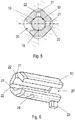
Figure 5 shows a cross-sectional view of the bushing ofFigure 4 . -
Figure 6 shows the bushing ofFigures 4 and5 in a perspective view. -
Figure 1 shows amirror system 1 comprising amirror mount 2 and ahousing 3. Themirror system 1 is especially designed to be employed in a Head-Up Display (HUD) in which a image projector projects information via a mirror mounted on themirror mount 2 onto a windshield of a vehicle, for example. Herein, thehousing 3 could be formed integrally with a dashboard of the vehicle or alternatively be mounted thereon. - The
mirror mount 2 comprises two substantiallycoaxial bores 4 for being pivotably suspended within thehousing 3 about an axis A. To this end, thehousing 3 itself has twoholes 5, each one of which lie adjacent to one of thebores 4 in a mounted position of themirror mount 2 in thehousing 3. - To suspend the
mirror mount 2 within thehousing 3, two bearing pins 6 (Figure 2 ) are lead through thebores 4 and holes 5, i.e., onebearing pin 6 is inserted into onebore 4 andadjacent hole 5 and theother bearing pin 6 into the respectiveother bore 4 and respectiveother hole 5. To prevent thebearing pin 6 from exiting thebore 4 andhole 5, twoscrews 7 are used, each one being threaded into thehousing 3 next to one of the bearing pins 6. Eachscrew 7 thus restricts the movement of one of the bearing pins 6 in an axial direction DA. Other restraining means other thanscrews 7 can be employed, too. - In
Figure 1 it can furthermore be seen that bores 4 were manufactured along axes 8 that deviate from the axis A about which themirror mount 2 is supposed to pivot. Similarly, due to manufacturing imprecisions, theholes 5 were manufactured alongaxes 9 that deviate from the axis A. As such, thebores 4 andholes 5 are only substantially coaxial. To nevertheless ensure a smooth rotation of themirror mount 2 about the axis A, measures as will be described in the following have been taken. -
Figures 3a and 3b show that each bore 4 of themirror mount 2 is provided with abushing 10 in therespective bore 4. Thebushing 10 is form-fitted into therespective bore 4 to ensure that thebearing pin 6 inserted therein can move freely within thebushing 10 without thebushing 10 moving with respect to themirror mount 2. - To compensate for the alignment errors of the
axes 8, 9, themirror mount 2 comprises two radially acting springs 11 for spring-loading eachbushing 10 against themirror mount 2 in a radial direction DR. Furthermore, themirror mount 2 comprises anaxially acting spring 12 for spring-loading at least one of the bearing pins 6 with respect to mirrormount 2 in an axial direction DA. In other words, the radially acting springs 11 press thebushing 10 against themirror mount 2 in a direction normal to the axis A and theaxially acting spring 12 presses one of the bearing pins 6 away from themirror mount 2, i.e., out of thebore 4 andbushing 10, respectively. - Said axial direction DA is to be understood as any direction parallel to the axis A and said radial direction DR is to be understood as any direction normal to the axis A. In the shown embodiment of
Figures 3a and 3b , the two radially acting springs 11 apply force onto thebushing 10 in the same direction. Alternatively, the two radially actingspring 11 could also apply force in different directions, as long as they are substantially normal to the axis A. - In the embodiments shown in
Figures 3 and 4 , the radially acting springs 11 are torsion springs having twolegs leg 13 is biased against a seat in themirror mount 2 and theother leg 14 is biased against therespective bushing 10. Torsion springs usually have a plurality ofwindings 15, which are in the present case located around a mountingbolt 16 of themirror mount 2 to ensure a safe fit of the torsion spring. Theleg 14 abutting against thebushing 10 is furthermore bent in a direction normal to the axis A to ensure a uniform transmission of force onto thebushing 10. - Alternatively, instead of using a torsion spring, the
radially acting spring 11 could also be embodied as a compression spring or any other type of spring. - The
mirror mount 2 comprises only one axially actingspring 12.Figure 3a shows onebore 4 with anaxially acting spring 12 andFigure 3b shows the respectiveother bore 4 of thesame mirror mount 2 without anaxially acting spring 12. Alternatively, also one axially actingspring 12 could be used for eachbushing 10, although this would lead to a system with too many degrees of freedom. In the shown embodiments, theaxially acting spring 12 is a compression spring, but also here a torsion spring or any other type of spring could be used. Theaxially acting spring 12 is inserted into thebore 4 of themirror mount 2 as is shown inFigure 3a . To spring-load thebearing pin 6 with respect to mirrormount 2, theaxially acting spring 12 abuts with one end on a taper or end of thebore 4 and with the other end against thebearing pin 6, i.e., theaxially acting spring 12 presses thebearing pin 6 away from themirror mount 2. - To reduce noises caused by the relative movement between the
bearing pin 6 and themirror mount 2, a slidingpin 17 can be inserted in thebore 4 between theaxially acting spring 12 and thebearing pin 6. Similarly, a slidingdisk 18 can be arranged in thebore 4 between themirror mount 2 and thebearing pin 6. To efficiently reduce noise occurring between thebearing pin 6 and themirror mount 2, the slidingpin 17 and slidingdisk 18 are made out of plastic. In such embodiments, thebearing pin 2 can directly abut on the slidingpin 17 and/or slidingdisk 18. Furthermore, other materials such as metals or ceramics could be used too. -
Figures 4 to 6 show thebushing 10 in detail. To allow thebushing 10 and thus also themirror mount 2 to rotate freely about thebearing pin 6, thebushing 10 is configured to support therespective bearing pin 6 on three contact points 19. To this end, thebushing 10 can have three inner surfaces that are aligned with respective angles towards each other. Alternatively, more than threecontact points 19 or a smooth inner surface could be utilised too. - Furthermore, from
Figure 5 it can be seen that thebushing 10 has aslit 20 and twojoints 21 to achieve a bearing play in the axial direction DA. As theradially acting spring 11 applies force onto thebushing 10, theslit 20 and thejoints 21 allow thebushing 10 to change its inner diameter. For example, if the bushing has three inner contact points 19, the distance between the contact points 19 can be adapted to thebearing pin 6 to overcome manufacturing misalignments of thebore 4. Said joints 21 can be formed byrecesses 22 in thebushing 10. Alternatively, joints that are more complex could be employed in thebushing 10, too. - More generally, the
bushing 10 can be a plain bearing and/or be a solid bushing, a slit bushing, or a clenched bushing. - Each
bore 4 can furthermore have a substantially quadratic cross-section area and thebushings 10 can have a corresponding cross-section area to achieve a form-fitting with respect to rotation in thebore 4. Alternatively, other polygonal cross-section areas could be chosen to achieve the form-fitting. - Alternatively or additionally, each
bushing 10 can further have a radially protrudingnose 23 to achieve a form-fitting with respect to a movement along the axial direction DA of thebore 4. Thebore 4 can have a corresponding recess for thenose 23 such that thenose 23 can easily be oriented in themirror mount 2 and also achieve a form-fitting with respect to rotation in thebore 4. - Furthermore, each
bushing 10 can have anotch 24 for receiving therespective leg 14 of the radially actingtorsion spring 11. Thenotch 24 has the purpose of achieving a form-fitting in an axial direction DA and also to ensure that force is evenly applied onto thebushing 10. - In most embodiments, the both
bushings 10 of themirror mount 2 are of the same type. In some embodiments, however, thebushings 10 can have different features. For example, only onebushing 10 could have aslit 20, one ormore joints 21, anose 23 of anotch 24. - In an alternative embodiment (not shown), the
mirror mount 2 could be provided withholes 5 through which the bearing pins 6 are led and thehousing 3 has two substantiallycoaxial bores 4, in each of which abushing 10 as described above for themirror mount 2 is provided. As this is a mechanically "reversed" embodiment, it is to be understood that all embodiments described above by means offigures 1 - 6 can also be applied for this embodiment. In this case, when themirror mount 2 is suspended in thehousing 3 andscrews 7 are used to restrict the axial movement of themirror mount 2, the twoscrews 7 are threaded into themirror mount 2 next to the bearing pins 6.
Claims (15)
- Mirror mount (2) for a Head-Up Display, the mirror mount (2) comprising two substantially coaxial bores (4) for being pivotably suspended in a housing (3) about an axis (A) by means of bearing pins (6),
characterised in that each bore (4) of the mirror mount (2) is provided with a bushing (10) in the respective bore (4),
wherein the mirror mount (2) comprises two radially acting springs (11) for spring-loading each bushing (10) against the mirror mount (2) in a radial direction (DR) and an axially acting spring (12) for spring-loading at least one of the bearing pins (6) with respect to the mirror mount (2) in an axial direction (DA). - Mirror mount (2) according to claim 1, wherein the radially acting springs (11) are torsion springs having two legs (13, 14), wherein one leg (13) is biased against a seat in the mirror mount (2) and the other leg (14) is biased against the respective bushing (10), wherein at least one of the bushings (10) preferably has a notch (24) for receiving the respective leg (14) of the torsion spring (11)
- Mirror mount (2) according to claim 1 or 2, wherein the axially acting spring (12) is a compression spring and is arranged within one of the bores (4) to spring-load the bearing pin (6) with respect to the mirror mount (2) in the axial direction (DA).
- Mirror mount (2) according to any one of claims 1 to 3, comprising a sliding pin (17) arranged on the side of the compression spring (12) facing the bearing pin (6), wherein the sliding pin (17) is preferably made out of plastic.
- Mirror mount (2) according to claim 3 or 4, comprising a sliding disk (18) arranged within one of the bores (4) for supporting the bearing pin (6) that is not spring-loaded, wherein the sliding disk (18) is preferably made out of plastic.
- Mirror mount (2) according to any one of claims 1 to 5, wherein at least one of the bushings (10) is configured to support the respective bearing pin (6) on three contact points (19).
- Mirror mount (2) according to any one of claims 1 to 6, wherein at least one of the bushings (10) has a slit (20) and two joints (21) to achieve a bearing play in the axial direction (DA), wherein the joints (21) are preferably formed by recesses (22) in the respective bushing (10).
- Mirror mount (2) according to any one of claims 1 to 7, wherein at least one of the bores (4) has a substantially quadratic cross-section area and the corresponding bushing (10) has a matching cross-section area to achieve a form-fitting with respect to rotation in the bore (4).
- Mirror mount (2) according to any one of claims 1 to 8, wherein at least one of the bushings (10) has a radially protruding nose (23) to achieve a form-fitting in the bore (4).
- Mirror system (1) comprising the mirror mount (2) according to any one of claims 1 to 9, the housing (3) and the two bearing pins (6), wherein the mirror mount (2) is suspended within the housing (3) by means of the bearing pins (6), wherein the mirror system (1) preferably comprises two screws (7) threaded into the housing (3) next to the bearing pins (6), each screw (7) for restricting the movement of one of the bearing pins (6) in the axial direction (DA).
- Housing (3) for mounting a mirror mount (2) for a Head-Up Display, the housing (3) comprising two substantially coaxial bores (4) for pivotably suspending the mirror mount (2) about an axis (A) by means of bearing pins (6),
characterised in that each bore (4) of the housing (3) is provided with a bushing (10) in the respective bore (4),
wherein the housing (3) comprises two radially acting springs (11) for spring-loading each bushing (10) against the housing (3) in a radial direction (DR) and an axially acting spring (12) for spring-loading at least one of the bearing pins (6) with respect to the housing (3) in an axial direction (DA). - Housing (3) according to claim 11, wherein the radially acting springs (11) are torsion springs having two legs (13, 14), wherein one leg (13) is biased against a seat in the housing (3) and the other leg (14) is biased against the respective bushing (10), wherein at least one of the bushings (10) preferably has a notch (24) for receiving the respective leg (14) of the torsion spring (11).
- Housing (3) according to claim 11 or 12, wherein the axially acting spring (12) is a compression spring and is arranged within one of the bores (4) to spring-load the bearing pin (6) with respect to the housing (3) in the axial direction (DA).
- Housing (3) according to any one of claims 11 to 13, wherein at least one of the bushings (10) has a slit (20) and two joints (21) to achieve a bearing play in the axial direction (DA), wherein the joints (21) are preferably formed by recesses (22) in the respective bushing (10).
- Mirror system (1) comprising the housing (3) according to any one of claims 11 to 14, the mirror mount (2) and the two bearing pins (6), wherein the mirror mount (2) is suspended within the housing (3) by means of the bearing pins (6), wherein the mirror system (1) preferably comprises two screws (7) threaded into the mirror mount (2) next to the bearing pins (6), each screw (7) for restricting the movement of one of the bearing pins (6) in the axial direction (DA).
Priority Applications (1)
| Application Number | Priority Date | Filing Date | Title |
|---|---|---|---|
| EP20181029.8A EP3926380B1 (en) | 2020-06-19 | 2020-06-19 | Mirror mount for a head-up display |
Applications Claiming Priority (1)
| Application Number | Priority Date | Filing Date | Title |
|---|---|---|---|
| EP20181029.8A EP3926380B1 (en) | 2020-06-19 | 2020-06-19 | Mirror mount for a head-up display |
Publications (2)
| Publication Number | Publication Date |
|---|---|
| EP3926380A1 true EP3926380A1 (en) | 2021-12-22 |
| EP3926380B1 EP3926380B1 (en) | 2024-02-07 |
Family
ID=71111294
Family Applications (1)
| Application Number | Title | Priority Date | Filing Date |
|---|---|---|---|
| EP20181029.8A Active EP3926380B1 (en) | 2020-06-19 | 2020-06-19 | Mirror mount for a head-up display |
Country Status (1)
| Country | Link |
|---|---|
| EP (1) | EP3926380B1 (en) |
Cited By (1)
| Publication number | Priority date | Publication date | Assignee | Title |
|---|---|---|---|---|
| DE102023115591A1 (en) | 2023-06-15 | 2024-12-19 | Valeo Schalter Und Sensoren Gmbh | Reflection assembly and reflection device for a head-up display, bearing support, head-up display and motor vehicle |
Citations (2)
| Publication number | Priority date | Publication date | Assignee | Title |
|---|---|---|---|---|
| JP2017076092A (en) * | 2015-10-16 | 2017-04-20 | 株式会社デンソー | Head-up display device |
| US20190285889A1 (en) * | 2018-03-16 | 2019-09-19 | Panasonic Intellectual Property Management Co., Lt d. | Rotating device for rotating rotation object and head-up display device |
-
2020
- 2020-06-19 EP EP20181029.8A patent/EP3926380B1/en active Active
Patent Citations (2)
| Publication number | Priority date | Publication date | Assignee | Title |
|---|---|---|---|---|
| JP2017076092A (en) * | 2015-10-16 | 2017-04-20 | 株式会社デンソー | Head-up display device |
| US20190285889A1 (en) * | 2018-03-16 | 2019-09-19 | Panasonic Intellectual Property Management Co., Lt d. | Rotating device for rotating rotation object and head-up display device |
Cited By (2)
| Publication number | Priority date | Publication date | Assignee | Title |
|---|---|---|---|---|
| DE102023115591A1 (en) | 2023-06-15 | 2024-12-19 | Valeo Schalter Und Sensoren Gmbh | Reflection assembly and reflection device for a head-up display, bearing support, head-up display and motor vehicle |
| WO2024256321A1 (en) | 2023-06-15 | 2024-12-19 | Valeo Schalter Und Sensoren Gmbh | Reflection assembly and reflection device for a head-up display, bearing mount, head-up display and motor vehicle |
Also Published As
| Publication number | Publication date |
|---|---|
| EP3926380B1 (en) | 2024-02-07 |
Similar Documents
| Publication | Publication Date | Title |
|---|---|---|
| EP3514605A1 (en) | Head-up display system | |
| CN216387586U (en) | Vehicle head-up display device | |
| US11474353B2 (en) | Head-up display apparatus for displaying virtual image | |
| US20190107717A1 (en) | Head-up display system | |
| JP2022093289A (en) | Fixation assembly | |
| US20210132332A1 (en) | Mirror device | |
| EP3926380B1 (en) | Mirror mount for a head-up display | |
| JP4905091B2 (en) | Mirror mounting structure | |
| US12259550B2 (en) | Adjustment device, adjustment unit, head-up display and motor vehicle | |
| US20040184171A1 (en) | Hand adjustable vehicle mirror mechanism | |
| JPH032810A (en) | High range and resolution defining mount and positioning device | |
| US11506864B2 (en) | Mirror device | |
| JP7601670B2 (en) | Display device | |
| JP2007322709A (en) | Optical member support mechanism, optical device, and interval adjustment member | |
| JP2007322709A5 (en) | ||
| JP7716930B2 (en) | display device | |
| US20040213521A1 (en) | Optical connector mount with six degrees of freedom | |
| JP2000338411A (en) | Objective lens for microscope | |
| JP7252741B2 (en) | Imaging device | |
| EP3982183B1 (en) | Apparatus comprising a mirror rotatably mounted to a housing | |
| CN222070931U (en) | Reflecting piece adjustment mechanism and head-up display device | |
| US20250314884A1 (en) | Rotary locking mounting process for reflection device of a head up display | |
| CN223077536U (en) | Scope bracket and sight assembly | |
| CN214895979U (en) | Optical device | |
| WO2026048740A1 (en) | Projection-type image display device |
Legal Events
| Date | Code | Title | Description |
|---|---|---|---|
| PUAI | Public reference made under article 153(3) epc to a published international application that has entered the european phase |
Free format text: ORIGINAL CODE: 0009012 |
|
| STAA | Information on the status of an ep patent application or granted ep patent |
Free format text: STATUS: THE APPLICATION HAS BEEN PUBLISHED |
|
| AK | Designated contracting states |
Kind code of ref document: A1 Designated state(s): AL AT BE BG CH CY CZ DE DK EE ES FI FR GB GR HR HU IE IS IT LI LT LU LV MC MK MT NL NO PL PT RO RS SE SI SK SM TR |
|
| B565 | Issuance of search results under rule 164(2) epc |
Effective date: 20201201 |
|
| STAA | Information on the status of an ep patent application or granted ep patent |
Free format text: STATUS: REQUEST FOR EXAMINATION WAS MADE |
|
| 17P | Request for examination filed |
Effective date: 20220620 |
|
| RBV | Designated contracting states (corrected) |
Designated state(s): AL AT BE BG CH CY CZ DE DK EE ES FI FR GB GR HR HU IE IS IT LI LT LU LV MC MK MT NL NO PL PT RO RS SE SI SK SM TR |
|
| GRAP | Despatch of communication of intention to grant a patent |
Free format text: ORIGINAL CODE: EPIDOSNIGR1 |
|
| STAA | Information on the status of an ep patent application or granted ep patent |
Free format text: STATUS: GRANT OF PATENT IS INTENDED |
|
| INTG | Intention to grant announced |
Effective date: 20230927 |
|
| GRAS | Grant fee paid |
Free format text: ORIGINAL CODE: EPIDOSNIGR3 |
|
| GRAA | (expected) grant |
Free format text: ORIGINAL CODE: 0009210 |
|
| STAA | Information on the status of an ep patent application or granted ep patent |
Free format text: STATUS: THE PATENT HAS BEEN GRANTED |
|
| AK | Designated contracting states |
Kind code of ref document: B1 Designated state(s): AL AT BE BG CH CY CZ DE DK EE ES FI FR GB GR HR HU IE IS IT LI LT LU LV MC MK MT NL NO PL PT RO RS SE SI SK SM TR |
|
| REG | Reference to a national code |
Ref country code: GB Ref legal event code: FG4D |
|
| REG | Reference to a national code |
Ref country code: CH Ref legal event code: EP |
|
| REG | Reference to a national code |
Ref country code: IE Ref legal event code: FG4D |
|
| REG | Reference to a national code |
Ref country code: DE Ref legal event code: R096 Ref document number: 602020025242 Country of ref document: DE |
|
| REG | Reference to a national code |
Ref country code: LT Ref legal event code: MG9D |
|
| REG | Reference to a national code |
Ref country code: NL Ref legal event code: MP Effective date: 20240207 |
|
| PG25 | Lapsed in a contracting state [announced via postgrant information from national office to epo] |
Ref country code: IS Free format text: LAPSE BECAUSE OF FAILURE TO SUBMIT A TRANSLATION OF THE DESCRIPTION OR TO PAY THE FEE WITHIN THE PRESCRIBED TIME-LIMIT Effective date: 20240607 |
|
| PG25 | Lapsed in a contracting state [announced via postgrant information from national office to epo] |
Ref country code: LT Free format text: LAPSE BECAUSE OF FAILURE TO SUBMIT A TRANSLATION OF THE DESCRIPTION OR TO PAY THE FEE WITHIN THE PRESCRIBED TIME-LIMIT Effective date: 20240207 |
|
| PG25 | Lapsed in a contracting state [announced via postgrant information from national office to epo] |
Ref country code: GR Free format text: LAPSE BECAUSE OF FAILURE TO SUBMIT A TRANSLATION OF THE DESCRIPTION OR TO PAY THE FEE WITHIN THE PRESCRIBED TIME-LIMIT Effective date: 20240508 |
|
| PG25 | Lapsed in a contracting state [announced via postgrant information from national office to epo] |
Ref country code: HR Free format text: LAPSE BECAUSE OF FAILURE TO SUBMIT A TRANSLATION OF THE DESCRIPTION OR TO PAY THE FEE WITHIN THE PRESCRIBED TIME-LIMIT Effective date: 20240207 Ref country code: RS Free format text: LAPSE BECAUSE OF FAILURE TO SUBMIT A TRANSLATION OF THE DESCRIPTION OR TO PAY THE FEE WITHIN THE PRESCRIBED TIME-LIMIT Effective date: 20240507 Ref country code: NL Free format text: LAPSE BECAUSE OF FAILURE TO SUBMIT A TRANSLATION OF THE DESCRIPTION OR TO PAY THE FEE WITHIN THE PRESCRIBED TIME-LIMIT Effective date: 20240207 |
|
| PG25 | Lapsed in a contracting state [announced via postgrant information from national office to epo] |
Ref country code: ES Free format text: LAPSE BECAUSE OF FAILURE TO SUBMIT A TRANSLATION OF THE DESCRIPTION OR TO PAY THE FEE WITHIN THE PRESCRIBED TIME-LIMIT Effective date: 20240207 |
|
| PG25 | Lapsed in a contracting state [announced via postgrant information from national office to epo] |
Ref country code: RS Free format text: LAPSE BECAUSE OF FAILURE TO SUBMIT A TRANSLATION OF THE DESCRIPTION OR TO PAY THE FEE WITHIN THE PRESCRIBED TIME-LIMIT Effective date: 20240507 Ref country code: NO Free format text: LAPSE BECAUSE OF FAILURE TO SUBMIT A TRANSLATION OF THE DESCRIPTION OR TO PAY THE FEE WITHIN THE PRESCRIBED TIME-LIMIT Effective date: 20240507 Ref country code: NL Free format text: LAPSE BECAUSE OF FAILURE TO SUBMIT A TRANSLATION OF THE DESCRIPTION OR TO PAY THE FEE WITHIN THE PRESCRIBED TIME-LIMIT Effective date: 20240207 Ref country code: LT Free format text: LAPSE BECAUSE OF FAILURE TO SUBMIT A TRANSLATION OF THE DESCRIPTION OR TO PAY THE FEE WITHIN THE PRESCRIBED TIME-LIMIT Effective date: 20240207 Ref country code: IS Free format text: LAPSE BECAUSE OF FAILURE TO SUBMIT A TRANSLATION OF THE DESCRIPTION OR TO PAY THE FEE WITHIN THE PRESCRIBED TIME-LIMIT Effective date: 20240607 Ref country code: HR Free format text: LAPSE BECAUSE OF FAILURE TO SUBMIT A TRANSLATION OF THE DESCRIPTION OR TO PAY THE FEE WITHIN THE PRESCRIBED TIME-LIMIT Effective date: 20240207 Ref country code: GR Free format text: LAPSE BECAUSE OF FAILURE TO SUBMIT A TRANSLATION OF THE DESCRIPTION OR TO PAY THE FEE WITHIN THE PRESCRIBED TIME-LIMIT Effective date: 20240508 Ref country code: FI Free format text: LAPSE BECAUSE OF FAILURE TO SUBMIT A TRANSLATION OF THE DESCRIPTION OR TO PAY THE FEE WITHIN THE PRESCRIBED TIME-LIMIT Effective date: 20240207 Ref country code: ES Free format text: LAPSE BECAUSE OF FAILURE TO SUBMIT A TRANSLATION OF THE DESCRIPTION OR TO PAY THE FEE WITHIN THE PRESCRIBED TIME-LIMIT Effective date: 20240207 Ref country code: BG Free format text: LAPSE BECAUSE OF FAILURE TO SUBMIT A TRANSLATION OF THE DESCRIPTION OR TO PAY THE FEE WITHIN THE PRESCRIBED TIME-LIMIT Effective date: 20240207 |
|
| PG25 | Lapsed in a contracting state [announced via postgrant information from national office to epo] |
Ref country code: PT Free format text: LAPSE BECAUSE OF FAILURE TO SUBMIT A TRANSLATION OF THE DESCRIPTION OR TO PAY THE FEE WITHIN THE PRESCRIBED TIME-LIMIT Effective date: 20240607 Ref country code: PL Free format text: LAPSE BECAUSE OF FAILURE TO SUBMIT A TRANSLATION OF THE DESCRIPTION OR TO PAY THE FEE WITHIN THE PRESCRIBED TIME-LIMIT Effective date: 20240207 |
|
| PG25 | Lapsed in a contracting state [announced via postgrant information from national office to epo] |
Ref country code: SE Free format text: LAPSE BECAUSE OF FAILURE TO SUBMIT A TRANSLATION OF THE DESCRIPTION OR TO PAY THE FEE WITHIN THE PRESCRIBED TIME-LIMIT Effective date: 20240207 Ref country code: PT Free format text: LAPSE BECAUSE OF FAILURE TO SUBMIT A TRANSLATION OF THE DESCRIPTION OR TO PAY THE FEE WITHIN THE PRESCRIBED TIME-LIMIT Effective date: 20240607 Ref country code: PL Free format text: LAPSE BECAUSE OF FAILURE TO SUBMIT A TRANSLATION OF THE DESCRIPTION OR TO PAY THE FEE WITHIN THE PRESCRIBED TIME-LIMIT Effective date: 20240207 Ref country code: LV Free format text: LAPSE BECAUSE OF FAILURE TO SUBMIT A TRANSLATION OF THE DESCRIPTION OR TO PAY THE FEE WITHIN THE PRESCRIBED TIME-LIMIT Effective date: 20240207 |
|
| PG25 | Lapsed in a contracting state [announced via postgrant information from national office to epo] |
Ref country code: DK Free format text: LAPSE BECAUSE OF FAILURE TO SUBMIT A TRANSLATION OF THE DESCRIPTION OR TO PAY THE FEE WITHIN THE PRESCRIBED TIME-LIMIT Effective date: 20240207 |
|
| PG25 | Lapsed in a contracting state [announced via postgrant information from national office to epo] |
Ref country code: SM Free format text: LAPSE BECAUSE OF FAILURE TO SUBMIT A TRANSLATION OF THE DESCRIPTION OR TO PAY THE FEE WITHIN THE PRESCRIBED TIME-LIMIT Effective date: 20240207 |
|
| PG25 | Lapsed in a contracting state [announced via postgrant information from national office to epo] |
Ref country code: CZ Free format text: LAPSE BECAUSE OF FAILURE TO SUBMIT A TRANSLATION OF THE DESCRIPTION OR TO PAY THE FEE WITHIN THE PRESCRIBED TIME-LIMIT Effective date: 20240207 Ref country code: EE Free format text: LAPSE BECAUSE OF FAILURE TO SUBMIT A TRANSLATION OF THE DESCRIPTION OR TO PAY THE FEE WITHIN THE PRESCRIBED TIME-LIMIT Effective date: 20240207 |
|
| PG25 | Lapsed in a contracting state [announced via postgrant information from national office to epo] |
Ref country code: SK Free format text: LAPSE BECAUSE OF FAILURE TO SUBMIT A TRANSLATION OF THE DESCRIPTION OR TO PAY THE FEE WITHIN THE PRESCRIBED TIME-LIMIT Effective date: 20240207 |
|
| PG25 | Lapsed in a contracting state [announced via postgrant information from national office to epo] |
Ref country code: SM Free format text: LAPSE BECAUSE OF FAILURE TO SUBMIT A TRANSLATION OF THE DESCRIPTION OR TO PAY THE FEE WITHIN THE PRESCRIBED TIME-LIMIT Effective date: 20240207 Ref country code: SK Free format text: LAPSE BECAUSE OF FAILURE TO SUBMIT A TRANSLATION OF THE DESCRIPTION OR TO PAY THE FEE WITHIN THE PRESCRIBED TIME-LIMIT Effective date: 20240207 Ref country code: RO Free format text: LAPSE BECAUSE OF FAILURE TO SUBMIT A TRANSLATION OF THE DESCRIPTION OR TO PAY THE FEE WITHIN THE PRESCRIBED TIME-LIMIT Effective date: 20240207 Ref country code: EE Free format text: LAPSE BECAUSE OF FAILURE TO SUBMIT A TRANSLATION OF THE DESCRIPTION OR TO PAY THE FEE WITHIN THE PRESCRIBED TIME-LIMIT Effective date: 20240207 Ref country code: DK Free format text: LAPSE BECAUSE OF FAILURE TO SUBMIT A TRANSLATION OF THE DESCRIPTION OR TO PAY THE FEE WITHIN THE PRESCRIBED TIME-LIMIT Effective date: 20240207 Ref country code: CZ Free format text: LAPSE BECAUSE OF FAILURE TO SUBMIT A TRANSLATION OF THE DESCRIPTION OR TO PAY THE FEE WITHIN THE PRESCRIBED TIME-LIMIT Effective date: 20240207 |
|
| REG | Reference to a national code |
Ref country code: DE Ref legal event code: R097 Ref document number: 602020025242 Country of ref document: DE |
|
| PG25 | Lapsed in a contracting state [announced via postgrant information from national office to epo] |
Ref country code: IT Free format text: LAPSE BECAUSE OF FAILURE TO SUBMIT A TRANSLATION OF THE DESCRIPTION OR TO PAY THE FEE WITHIN THE PRESCRIBED TIME-LIMIT Effective date: 20240207 |
|
| PLBE | No opposition filed within time limit |
Free format text: ORIGINAL CODE: 0009261 |
|
| STAA | Information on the status of an ep patent application or granted ep patent |
Free format text: STATUS: NO OPPOSITION FILED WITHIN TIME LIMIT |
|
| PG25 | Lapsed in a contracting state [announced via postgrant information from national office to epo] |
Ref country code: IT Free format text: LAPSE BECAUSE OF FAILURE TO SUBMIT A TRANSLATION OF THE DESCRIPTION OR TO PAY THE FEE WITHIN THE PRESCRIBED TIME-LIMIT Effective date: 20240207 |
|
| 26N | No opposition filed |
Effective date: 20241108 |
|
| REG | Reference to a national code |
Ref country code: AT Ref legal event code: UEP Ref document number: 1655750 Country of ref document: AT Kind code of ref document: T Effective date: 20240207 |
|
| PG25 | Lapsed in a contracting state [announced via postgrant information from national office to epo] |
Ref country code: MC Free format text: LAPSE BECAUSE OF FAILURE TO SUBMIT A TRANSLATION OF THE DESCRIPTION OR TO PAY THE FEE WITHIN THE PRESCRIBED TIME-LIMIT Effective date: 20240207 |
|
| REG | Reference to a national code |
Ref country code: CH Ref legal event code: PL |
|
| PG25 | Lapsed in a contracting state [announced via postgrant information from national office to epo] |
Ref country code: LU Free format text: LAPSE BECAUSE OF NON-PAYMENT OF DUE FEES Effective date: 20240619 |
|
| GBPC | Gb: european patent ceased through non-payment of renewal fee |
Effective date: 20240619 |
|
| PG25 | Lapsed in a contracting state [announced via postgrant information from national office to epo] |
Ref country code: IE Free format text: LAPSE BECAUSE OF NON-PAYMENT OF DUE FEES Effective date: 20240619 |
|
| PG25 | Lapsed in a contracting state [announced via postgrant information from national office to epo] |
Ref country code: SI Free format text: LAPSE BECAUSE OF FAILURE TO SUBMIT A TRANSLATION OF THE DESCRIPTION OR TO PAY THE FEE WITHIN THE PRESCRIBED TIME-LIMIT Effective date: 20240207 Ref country code: BE Free format text: LAPSE BECAUSE OF NON-PAYMENT OF DUE FEES Effective date: 20240630 Ref country code: CH Free format text: LAPSE BECAUSE OF NON-PAYMENT OF DUE FEES Effective date: 20240630 |
|
| PG25 | Lapsed in a contracting state [announced via postgrant information from national office to epo] |
Ref country code: GB Free format text: LAPSE BECAUSE OF NON-PAYMENT OF DUE FEES Effective date: 20240619 |
|
| REG | Reference to a national code |
Ref country code: BE Ref legal event code: MM Effective date: 20240630 |
|
| PGFP | Annual fee paid to national office [announced via postgrant information from national office to epo] |
Ref country code: DE Payment date: 20250618 Year of fee payment: 6 |
|
| PGFP | Annual fee paid to national office [announced via postgrant information from national office to epo] |
Ref country code: FR Payment date: 20250618 Year of fee payment: 6 |
|
| PGFP | Annual fee paid to national office [announced via postgrant information from national office to epo] |
Ref country code: AT Payment date: 20250616 Year of fee payment: 6 |
|
| PG25 | Lapsed in a contracting state [announced via postgrant information from national office to epo] |
Ref country code: CY Free format text: LAPSE BECAUSE OF FAILURE TO SUBMIT A TRANSLATION OF THE DESCRIPTION OR TO PAY THE FEE WITHIN THE PRESCRIBED TIME-LIMIT; INVALID AB INITIO Effective date: 20200619 |
|
| PG25 | Lapsed in a contracting state [announced via postgrant information from national office to epo] |
Ref country code: HU Free format text: LAPSE BECAUSE OF FAILURE TO SUBMIT A TRANSLATION OF THE DESCRIPTION OR TO PAY THE FEE WITHIN THE PRESCRIBED TIME-LIMIT; INVALID AB INITIO Effective date: 20200619 |