EP3926367B1 - Vorrichtung und verfahren zur messung der strahlungsdosisverteilung von einer nahen strahlungsquelle - Google Patents
Vorrichtung und verfahren zur messung der strahlungsdosisverteilung von einer nahen strahlungsquelle Download PDFInfo
- Publication number
- EP3926367B1 EP3926367B1 EP20768932.4A EP20768932A EP3926367B1 EP 3926367 B1 EP3926367 B1 EP 3926367B1 EP 20768932 A EP20768932 A EP 20768932A EP 3926367 B1 EP3926367 B1 EP 3926367B1
- Authority
- EP
- European Patent Office
- Prior art keywords
- insertion tool
- brachytherapy
- radiation
- housing
- cover
- Prior art date
- Legal status (The legal status is an assumption and is not a legal conclusion. Google has not performed a legal analysis and makes no representation as to the accuracy of the status listed.)
- Active
Links
Images




Classifications
-
- A—HUMAN NECESSITIES
- A61—MEDICAL OR VETERINARY SCIENCE; HYGIENE
- A61N—ELECTROTHERAPY; MAGNETOTHERAPY; RADIATION THERAPY; ULTRASOUND THERAPY
- A61N5/00—Radiation therapy
- A61N5/10—X-ray therapy; Gamma-ray therapy; Particle-irradiation therapy
- A61N5/1001—X-ray therapy; Gamma-ray therapy; Particle-irradiation therapy using radiation sources introduced into or applied onto the body; brachytherapy
-
- A—HUMAN NECESSITIES
- A61—MEDICAL OR VETERINARY SCIENCE; HYGIENE
- A61N—ELECTROTHERAPY; MAGNETOTHERAPY; RADIATION THERAPY; ULTRASOUND THERAPY
- A61N5/00—Radiation therapy
- A61N5/10—X-ray therapy; Gamma-ray therapy; Particle-irradiation therapy
- A61N5/1001—X-ray therapy; Gamma-ray therapy; Particle-irradiation therapy using radiation sources introduced into or applied onto the body; brachytherapy
- A61N5/1007—Arrangements or means for the introduction of sources into the body
-
- A—HUMAN NECESSITIES
- A61—MEDICAL OR VETERINARY SCIENCE; HYGIENE
- A61N—ELECTROTHERAPY; MAGNETOTHERAPY; RADIATION THERAPY; ULTRASOUND THERAPY
- A61N5/00—Radiation therapy
- A61N5/10—X-ray therapy; Gamma-ray therapy; Particle-irradiation therapy
- A61N5/1048—Monitoring, verifying, controlling systems and methods
- A61N5/1075—Monitoring, verifying, controlling systems and methods for testing, calibrating, or quality assurance of the radiation treatment apparatus
-
- G—PHYSICS
- G01—MEASURING; TESTING
- G01D—MEASURING NOT SPECIALLY ADAPTED FOR A SPECIFIC VARIABLE; ARRANGEMENTS FOR MEASURING TWO OR MORE VARIABLES NOT COVERED IN A SINGLE OTHER SUBCLASS; TARIFF METERING APPARATUS; MEASURING OR TESTING NOT OTHERWISE PROVIDED FOR
- G01D11/00—Component parts of measuring arrangements not specially adapted for a specific variable
- G01D11/24—Housings ; Casings for instruments
- G01D11/245—Housings for sensors
-
- G—PHYSICS
- G01—MEASURING; TESTING
- G01T—MEASUREMENT OF NUCLEAR OR X-RADIATION
- G01T1/00—Measuring X-radiation, gamma radiation, corpuscular radiation, or cosmic radiation
- G01T1/02—Dosimeters
- G01T1/10—Luminescent dosimeters
-
- G—PHYSICS
- G01—MEASURING; TESTING
- G01T—MEASUREMENT OF NUCLEAR OR X-RADIATION
- G01T1/00—Measuring X-radiation, gamma radiation, corpuscular radiation, or cosmic radiation
- G01T1/16—Measuring radiation intensity
- G01T1/161—Applications in the field of nuclear medicine, e.g. in vivo counting
-
- G—PHYSICS
- G01—MEASURING; TESTING
- G01T—MEASUREMENT OF NUCLEAR OR X-RADIATION
- G01T1/00—Measuring X-radiation, gamma radiation, corpuscular radiation, or cosmic radiation
- G01T1/29—Measurement performed on radiation beams, e.g. position or section of the beam; Measurement of spatial distribution of radiation
- G01T1/2914—Measurement of spatial distribution of radiation
-
- G—PHYSICS
- G01—MEASURING; TESTING
- G01T—MEASUREMENT OF NUCLEAR OR X-RADIATION
- G01T7/00—Details of radiation-measuring instruments
Definitions
- the present invention relates to an apparatus and method for measuring the distribution of radiation dose from a brachytherapy radiation source.
- Radiation therapy is a clinical medicine method that treats patients using radiation having a very short wavelength and high energy, and is one of three major cancer treatments together with surgery and chemotherapy. Although radiation therapy treats malignant tumors mainly called cancer, radiation therapy also treats benign tumors or some benign diseases.
- Radiation therapy may be classified as teletherapy and brachytherapy depending on the position of a radiation applicator.
- Teletherapy is a treatment method that applies radiation using various kinds of equipment outside the human body, and may be classified as photon beam therapy, electron beam therapy, or particle therapy (neutron therapy, proton therapy, etc.) depending on the kind of radiation that is used.
- photon beam therapy electron beam therapy
- particle therapy neutral therapy, proton therapy, etc.
- various radiation generators may be used, therefore, a radiation generator that is the most widely used is a linear accelerator.
- Brachytherapy is a method of locating a radiation generator or a radiation source in the human body or at the surface of the human body to apply radiation to a limited region, and may be classified as intracavitary radiotherapy, intraluminal radiotherapy, interstitial radiotherapy, or contact therapy depending on the space into which the radiation generator or the radiation source is inserted or a method in which the radiation generator or the radiation source is inserted.
- a brachytherapy insertion tool 1 which is configured to be inserted into a human body, includes an outer body 10 and an inner body 20 located in the outer body 10.
- the middle portion of the outer body 10 in a longitudinal direction thereof is bent at a predetermined angle such that the front part of the brachytherapy insertion tool 1 can be easily inserted into the human body.
- the inner body 20 is divided into a first portion 21 and a second portion 22, and the first portion 21 and the second portion 22 are connected to each other via a flexible connection portion 23.
- the connection portion 23 is located at the bent portion of the outer body 10.
- first portion 21, the connection portion 23, and the second portion 22 are connected to each other, and a radiation source (not shown) may be located in the second portion 22 via the first portion 21 and the connection portion 23.
- the second portion 22 is inserted into the human body so as to be located at a place adjacent to a tumor.
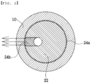
- the second portion 22 may be divided into a first region 24a and a second region 24b.
- the first region 24a has radiation shielding
- the second region 24b has no radiation shielding. As a result, a larger amount of radiation is emitted from the second region 24b than the first region 24a.
- control is performed such that the first region 24a faces a normal site and the second region 24b faces a tumor site in the state in which the second portion 22 is inserted into the human body.
- Radiation generated from the radiation source may be emitted through the second region 24b and the portion of the outer body 10 that faces the second region 24b so as to concentrate on the tumor.
- the direction of the second region 24b must be adjusted such that the second region faces the tumor in the state in which the brachytherapy insertion tool 1 is inserted into the human body.
- the second portion 22 Since the second portion 22 is located in the outer body 10, it is not possible to directly check by eye whether an error is generated. Therefore, measurement as to whether the second portion 22, in which the radiation source is located, is accurately rotated together with the first portion 21 and thus the second region 24b faces a predetermined position (a tumor site) is essentially required.
- WO 00/79302 A1 provides three-dimensional liquid scintillation dosimetry system.
- WO 2021/116756 A1 provides system and method for detecting and tracking a radiation source controlled by an afterloader used for brachytherapy.
- the present invention provides technology capable of measuring whether radiation from a radiation source of a brachytherapy insertion tool is accurately applied to a predetermined position.
- An apparatus for measuring the distribution of radiation dose emitted from a brachytherapy insertion tool includes a housing having defined therein a measurement space in which the brachytherapy insertion tool is located, a fluorescent member disposed at the housing, the fluorescent member being configured to react with radiation emitted to the measurement space and to emit light, a camera disposed in the housing, and a cover coupled to one surface of the housing, the cover being configured to cover the fluorescent member.
- the fluorescent member is flat, is disposed perpendicular to the brachytherapy insertion tool guided to the measurement space, and is provided with a fluorescent through-hole, through which the brachytherapy insertion tool is inserted so as to be installed.
- Radiation emitted from a brachytherapy radiation source transferred to the brachytherapy insertion tool may be applied to the fluorescent member in the measurement space to emit light, and an image of the light may be captured by the camera.
- the cover may include a cover body having a cover through-hole, through which the brachytherapy insertion tool is inserted, formed therein.
- the cover may further include an insertion tool guide formed at the cover body, the insertion tool guide being provided with a guide recess configured to guide the brachytherapy insertion tool to the cover through-hole.
- the cover may further include a coupling pin inserted into the housing through the cover, the coupling pin being configured to prevent movement of the cover.
- the housing may block external light so as not to be introduced into the measurement space when the brachytherapy insertion tool is mounted to the cover.
- the camera may be disposed at one side of the measurement space, and the center of a lens of the camera is located on the same line as the center of the brachytherapy insertion tool inserted into the measurement space.
- the apparatus may further include a lifting unit disposed at the housing, the lifting unit being configured to set the position of the fluorescent member.
- a method of measuring the distribution of radiation dose from a brachytherapy radiation source includes disposing a fluorescent member at a housing having a camera disposed therein, coupling the housing and a cover to each other in the state in which the fluorescent member is interposed therebetween, inserting the front end of a brachytherapy insertion tool into a measurement space of the housing, transferring a brachytherapy radiation source into the brachytherapy insertion tool, and capturing an image of the measurement space to which radiation is applied and analyzing the captured image.
- the portion of the fluorescent member to which radiation from the brachytherapy radiation source is applied reacts with the radiation and generates light, brightness of the light varies depending on distribution of the radiation, and the position at which the light is bright is calculated to measure the direction in which the brachytherapy insertion tool has no shielding.
- the fluorescent member is flat, is disposed perpendicular to the brachytherapy insertion tool guided to the measurement space, and is provided with a fluorescent through-hole, through which the brachytherapy insertion tool is inserted so as to be installed.
- a fluorescent member reacts with radiation applied to a measurement space and emits light.
- An image of the emitted light may be captured by a camera, and the captured image may be analyzed to measure the angle of radiation dose. Consequently, it is possible to accurately measure the angle of radiation dose from a brachytherapy insertion tool, whereby it is possible to improve reliability of brachytherapy.
- the embodiment of the present invention it is possible to accurately apply radiation to a tumor site through measurement of the angle of radiation dose, whereby it is possible to improve the effect of radiation therapy.
- the front end of the brachytherapy insertion tool is inserted perpendicularly through the fluorescent member, and radiation is applied under the fluorescent member in a direction parallel to the fluorescent member. Since the radiation is emitted in a direction parallel to the fluorescent member, it is possible to more accurately measure the angle of radiation dose from the brachytherapy insertion tool.
- the position of the fluorescent member is changed by a lifting unit, whereby three-dimensional radiation dose distribution measurement is possible. As a result, it is possible to more accurately measure the direction in which a second region faces.
- FIGS. 3 to 7 a brachytherapy insertion tool according to an embodiment of the present invention will be described with reference to FIGS. 3 to 7 .
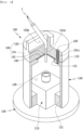
- FIG. 3 is a perspective view showing an apparatus for measuring the distribution of radiation dose from a brachytherapy insertion tool according to an embodiment of the present invention
- FIG. 4 is a sectional perspective view showing the interior of FIG. 3
- FIG. 5 is an exploded perspective view of FIG. 3
- FIG. 6 is a sectional view taken along line VI-VI of FIG. 3
- FIG. 7 is a sectional view taken along line VII-VII of FIG. 6 .
- the apparatus 100 for measuring the distribution of radiation dose from the brachytherapy insertion tool includes a housing 130, a fluorescent member 140, and a cover 150, and measures whether radiation applied from a radiation source of the brachytherapy insertion tool is accurately applied to a predetermined position. That is, the radiation dose distribution measurement apparatus measures quality of the brachytherapy insertion tool.
- the housing 130 is disposed on a base 120 having a predetermined area, and the interior of the housing is vertically bored such that a measurement space 135 is defined in the housing.
- the housing 130 is provided in the upper surface thereof with an opening hole 131, which is connected to the measurement space 135.
- the housing 130 is provided in the upper surface thereof with a seating recess 132, a rotation preventing recess 133, and a separation recess 132a.
- the separation recess 132a and the seating recess 132 are connected to each other, and the seating recess 132 is connected to the opening hole 131.
- the rotation preventing recess 133 is spaced apart from the seating recess 132.
- the depth of the separation recess 132a from the upper surface of the housing 130 is greater than the depth of the seating recess 132 from the upper surface of the housing.
- the housing 130 is provided on the edge of the upper surface thereof with a stepped protrusion extending in a circumferential direction.
- the housing 130 is shown as having a cylindrical shape; however, the shape of the housing 130 may be changed depending on design of the radiation dose distribution measurement apparatus 100.
- the housing 130 is configured such that no light is introduced into the measurement space 135.
- the housing 130 may be opaque, or a light blocking layer (not shown) may be formed on the surface of the housing 130.
- the housing 130 may be made of a material capable of shielding radiation.
- the base 120 is coupled to the housing 130, and a camera 110 is disposed at the base 120.
- the camera 110 may be located in the measurement space 135 as a result of coupling between the base 120 and the housing 130.
- a fixing means 121 configured to wrap the camera 110 is disposed in the housing 130 such that the base 120 and the housing 130 are coupled to each other in place.
- the housing 130 is consistently coupled to the camera 110 under guidance of the fixing means 121.
- the fixing means 121 may be variously changed depending on design of the radiation dose distribution measurement apparatus 100.
- a lens of the camera 110 faces the center of the opening hole 131 in the measurement space 135.
- the camera may be a charge-coupled device (CCD) camera.
- CCD charge-coupled device
- the fluorescent member 140 is flat while having a predetermined thickness, and is seated in the seating recess 132 of the housing 130.
- the upper surface of the fluorescent member 140 does not protrude from the upper surface of the housing 130.
- the middle part of the fluorescent member 140 is located at the opening hole 131, and the edge part of the fluorescent member is supported by the bottom of the seating recess 132.
- the fluorescent member 140 is provided in the center thereof with a fluorescent through-hole 141, through which the front end of the brachytherapy insertion tool 1 that is inserted into the measurement space 135 is inserted.
- the fluorescent through-hole 141 is connected to the measurement space 135 via the opening hole 131.
- the front end of the brachytherapy insertion tool 1 may be inserted into the measurement space 135 via the fluorescent through-hole 141 and the opening hole 131. At this time, the brachytherapy insertion tool 1 is inserted through the fluorescent through-hole 141 in a state of being perpendicular to the flat surface of the fluorescent member 140.
- the fluorescent member 140 may emit light in response to radiation discharged from the radiation source of the brachytherapy insertion tool 1.
- the light may be visible light, and brightness of light that is emitted varies depending on the distribution of the radiation.
- the camera 110 may capture an image of light that is emitted. Since the housing 130 blocks external light so as not to be introduced into the measurement space 135, the camera may more accurately capture an image of light that is emitted, whereby it is possible to more accurately measure the distribution of radiation dose.
- a portion of the fluorescent member 140 overlaps about half of the separation recess 132a.
- a space is defined between a portion of the fluorescent member 140 and a portion of the bottom of the separation recess 132a.
- a finger is put in the space through the portion of the separation recess 132a that does not overlap the fluorescent member 140 to lift the fluorescent member 140 such that the fluorescent member 140 is separated from the seating recess 132.
- the cover 150 includes a cover body 151 and a guide block 152.
- the cover 150 blocks external light so as not to be introduced into the measurement space 135, in the same manner as the housing 130.
- the cover 150 may be opaque, or a light blocking layer (not shown) may be formed on the surface of the cover.
- the cover body 141 is disposed on the upper surface of the housing 130, and is provided on the edge of the lower surface thereof with a catching protrusion (not shown) extending in a circumferential direction, the catching protrusion being configured to be coupled to the stepped protrusion of the housing 130. Movement of the cover body 151 in a direction perpendicular to a longitudinal direction of the housing 130 is prevented as a result of coupling between the stepped protrusion and the catching protrusion. The lower surface of the cover body 151 abuts the fluorescent member 140 in the state in which the cover body is coupled to the housing 130, whereby the fluorescent member 140 is in tight contact with the seating recess 132.
- the cover body 151 is provided in the center thereof with a cover through-hole 151b, which is connected to the fluorescent through-hole 141.
- a coupling pin 160 is inserted in the state in which the rotation preventing recess 133 and the pin hole 151c are aligned with each other.
- the lower end of the coupling pin 160 is inserted through the pin hole 151c and is located in the rotation preventing recess 133.
- the cover body 151 is fixed by the coupling pin 160 located in the pin hole 151c and the rotation preventing recess 133, whereby rotation of the cover body in a circumferential direction of the housing 130 is prevented.
- the guide block 152 is formed on the upper surface of the cover body 151, and is provided with a guide recess 152a extending in a longitudinal direction.
- the guide recess 152a is connected to the cover through-hole 151b.
- the brachytherapy insertion tool 1 is bent at a predetermined point thereof, and the front end (a second portion 22, see FIG. 1 ) of the brachytherapy insertion tool on the basis of the bent portion thereof is located in the measurement space 135 via the fluorescent and cover through-holes 141 and 151b. At this time, the front end of the brachytherapy insertion tool 1 is aligned with the vertical center 130c of each of the fluorescent and cover through-holes 141 and 151b. The rear end (a first portion 21, see FIG. 1 ) of the brachytherapy insertion tool 1 is inclined from the vertical center by a predetermined angle 1d.
- the first portion 21 of the brachytherapy insertion tool 1 is located in the guide recess 152a, and the circumference of the rear end abuts the inner surface of the guide recess 152a. Since the circumference of the rear end abuts the inner surface of the guide recess 152a, movement of the brachytherapy insertion tool 1 is prevented in a state of being mounted in the radiation dose distribution measurement apparatus 100. In addition, the brachytherapy insertion tool 1 may always be located at the same position when being mounted in the radiation dose distribution measurement apparatus 100. Consequently, it is possible to prevent the occurrence of an error due to mounting when the distribution of radiation dose is measured.
- a method of measuring the distribution of radiation dose from a brachytherapy insertion tool includes a step (S10) of disposing a fluorescent member at a housing having a camera installed therein, a step (S20) of coupling a cover to the housing, a step (S30) of inserting the front end of a brachytherapy insertion tool into the housing, a step (S40) of applying, by the brachytherapy insertion tool, radiation into the housing, and a step (S50) of capturing, by the camera, an image of the interior of the housing.
- a base 120 is coupled to the housing 130, and the camera 110 is disposed at the base 120.
- the housing 130 and the base 120 are coupled to each other in the state in which a fixing means 121 is installed in the housing 130.
- the camera 110 is located in a measurement space 135 as a result of coupling between the base 120 and the housing 130, and the housing 130 and the camera 110 are consistently coupled to each other by the fixing means 121. Consequently, the center of a lens of the camera 110 and the vertical center of an opening hole 131 of the housing 130 are aligned with each other.
- the fluorescent member 140 is disposed on the upper surface of the housing 130 (S10). At this time, the edge of the fluorescent member 140 is located in a seating recess 132.
- the fluorescent member 140 is spaced apart from the camera 110 while facing the lens of the camera such that the center of a fluorescent through-hole 141 and the center of the lens of the camera 110 are aligned with each other.
- the fluorescent member 140 is disposed at the housing 130 after the base 120 and the housing 130 are coupled to each other.
- the base 120 and the housing 130 may be coupled to each other after the fluorescent member 140 is disposed at the housing 130.
- the housing 130 and the cover 150 When coupling the housing 130 and the cover 150 to each other, the housing 130 and the cover 150 are coupled to each other in the state in which a stepped protrusion of the housing 130 and a catching protrusion of the cover 150 are coupled to each other (S20). Subsequently, a pin hole 151c and a rotation preventing recess 133 are aligned with each other, and then a coupling pin 160 is inserted into the rotation preventing recess 133 via the pin hole 151c. The lower end of the coupling pin 160 is located in the rotation preventing recess 133 via the pin hole 151c.
- Movement of the cover 150 in directions X and Y perpendicular to a longitudinal direction Z of the housing 130 is prevented as a result of coupling between the stepped protrusion of the housing 130 and the catching protrusion of the cover 150, and rotation of the cover 150 in a circumferential direction R of the housing 130 is prevented by the coupling pin 160.
- the cover 150 is fixed at a predetermined position, whereby movement of the cover is prevented.
- the front end of the brachytherapy insertion tool 1 is inserted into the measurement space 135 via through-holes 141 and 151b (S30).
- a second portion 22 of the brachytherapy insertion tool 1 is located in the measurement space 135 as a result of insertion of the front end of the brachytherapy insertion tool.
- the rear end of the brachytherapy insertion tool 1 is located in a guide recess 152a, and the outer circumference of the rear end abuts the inner surface of the guide recess 152a.
- the brachytherapy insertion tool 1 is fixed to the cover 150. Since the brachytherapy insertion tool 1 is fixed to the cover 150, a second portion 22 of the brachytherapy insertion tool consistently abuts the fluorescent member 140.
- a first portion 21 of the brachytherapy insertion tool is rotated.
- the second portion 22 is rotated together with the first portion 21 through a connection portion 23, whereby a second region 24b of the brachytherapy insertion tool faces a predetermined position (a tumor site).
- a radiation source is inserted into the brachytherapy insertion tool 1 so as to be located at the second portion 22 of the brachytherapy insertion tool (S40).
- the position of the radiation source may be adjusted.
- the radiation source may be located at the second portion 22, which abuts the fluorescent member 140, such that the fluorescent member 140 and the radiation source are located on the same line.
- the radiation source may be further inserted so as to be located at the end of the second portion 22.
- the radiation source may be located higher than the fluorescent member 140 without being inserted through the fluorescent member 140. Consequently, it is possible to appropriately adjust the position of the radiation source.
- Radiation is emitted from the radiation source inserted into the brachytherapy insertion tool 1 in all directions.
- a relatively large amount of radiation is applied to the measurement space 135 through the second region 24b, which has no shielding.
- the emitted radiation reacts with the fluorescent member 140, whereby light is generated.
- the radiation source when the radiation source is located on the same line as the fluorescent member 140, radiation is emitted in all directions in a state of being parallel to the fluorescent member 140. Since a relatively large amount of radiation is applied through the second region 24b, the portion of the fluorescent member 140 aligned with the second region 24b is brighter than the other portions of the fluorescent member.
- the radiation source is located at the end of the second portion 22
- radiation is emitted to the measurement space 135.
- Radiation collides with the surface of the fluorescent member 140, and the fluorescent member 140 reacts with the radiation, whereby light is generated. Since a larger amount of radiation is emitted from the second region 24b than a first region 24a, brighter light is generated in the portion of the fluorescent member 140 to which the radiation emitted from the second region 24b is applied than in other portions of the fluorescent member.
- Brightness of light emitted from the fluorescent member 140 varies depending on the distribution of radiation. Consequently, the surroundings of the second region 24b may be brighter than the surroundings of the first region 24a.
- the camera 110 photographs the fluorescent member 140 in the measurement space 135 to acquire an image (see FIG. 9 ).
- a controller (not shown) calculates the position at which light is bright through the acquired image to measure the direction in which the second region 24b of the brachytherapy insertion tool 1, which has no shielding, faces. That is, the controller calculates a deviated angle D of the second region 24b on the basis of 0° through the brightness of light from the acquired image.
- the direction of the deviated angle D is determined by rotating an inner body 20 (see FIG. 1 ) through manipulation of a manipulator (not shown) of the brachytherapy insertion tool 1.
- a manipulator not shown
- the second region 24b must be rotated 30° together with the manipulator.
- the controller determines whether the second region 24b has been rotated 30°.
- center coordinates are determined.
- the center coordinates become a criterion for angle calculation.
- signal intensity for each angle is extracted.
- Signal intensity may be extracted using a contour line.
- a measured signal has a sine wave.
- the difference between the highest point and the lowest point of the measured signal must be great, and noise must not be mixed with the measured signal.
- smoothing is performed.
- an average is calculated to increase a signal-to-noise ratio (SNR).
- a parameter such as a threshold value or order of a fitting function, may be used to easily extract the portion that has the greatest signal part from the measured signal.
- the contour line passes through the point distant from the center in the direction in which intensity is high, and the contour line passes through the point closed to the center in the direction in which intensity is low.
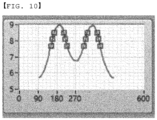
- the graph shown in FIG. 10 There are two mountains and a valley therebetween.
- the actual direction of radiation is the direction of the valley between the mountains.
- the directions of the two mountains are accurately checked, and then the middle between the two directions is found to find the actual direction of radiation. Consequently, the distance from the center to the contour line is drawn to detect the direction in which the signal is strong.
- signal intensity may be extracted using a concentric circle.
- One concentric circle having a uniform distance from a predetermined center is specified, and signal intensity is drawn along the concentric circle to detect the direction in which the signal is strong.
- Signal intensity for each angle is extracted to detect a peak.
- one or more peaks may be detected. That is, a peak is generated from a signal in a direction from 0° to 360°. There may be no peak or two peaks depending on signal distribution or the direction in which 0° is defined. In the case in which there is no peak, the definition of 0° is changed (phase shift) to detect a peak, and then 0° is changed so as to have the original definition.
- the direction of the second region 24b is one, and the median between the two peaks may be the direction.
- the direction of the second region may be median between the two peaks or a value obtained by adding 180° thereto depending on the distance between the two peaks.
- the angle at which the peak is located may be output to measure the position at which the second region 24b is deviated (rotated) on the basis of 0°.
- a radiation dose distribution measurement apparatus further includes a lifting unit (not shown) while including the components according to the embodiment shown in FIGS. 1 to 10 without change.
- the lifting unit includes a motor, a screw, and a nut, and is disposed at the housing 130 or the cover 150 so as to be connected to the fluorescent member 140.
- the screw and the nut form a pair.
- the nut is connected to the fluorescent member 140, and the screw is coupled to the nut.
- the screw is connected to the motor. When the screw is rotated by the motor, the fluorescent member 140, to which the nut is connected, may move upwards and downwards.
- a space (not shown) in which the fluorescent member 140 is movable is formed between the housing 130, at which the fluorescent member 140 is located, and the cover 150.
- the fluorescent member 140 may move in a direction toward the camera 110 or a direction distant from the camera 110 in response to rotation of the screw.
- the fluorescent member 140 may be rectilinearly moved in the space by the lifting unit, whereby the position of the fluorescent member 140 may be variously changed depending on measurement conditions.
Landscapes
- Health & Medical Sciences (AREA)
- Physics & Mathematics (AREA)
- Life Sciences & Earth Sciences (AREA)
- General Physics & Mathematics (AREA)
- Engineering & Computer Science (AREA)
- Biomedical Technology (AREA)
- High Energy & Nuclear Physics (AREA)
- Molecular Biology (AREA)
- Spectroscopy & Molecular Physics (AREA)
- Nuclear Medicine, Radiotherapy & Molecular Imaging (AREA)
- General Health & Medical Sciences (AREA)
- Animal Behavior & Ethology (AREA)
- Pathology (AREA)
- Radiology & Medical Imaging (AREA)
- Public Health (AREA)
- Veterinary Medicine (AREA)
- Optics & Photonics (AREA)
- Medical Informatics (AREA)
- Radiation-Therapy Devices (AREA)
- Measurement Of Radiation (AREA)
Claims (8)
- Vorrichtung (100) zum Messen einer Verteilung einer Strahlungsdosis von einer Brachytherapie-Strahlungsquelle, wobei die Vorrichtung (100) dazu eingerichtet ist, die Verteilung der von einem Brachytherapie-Einführwerkzeug (1) emittierten Strahlungsdosis zu messen, wobei die Vorrichtung (100) umfasst:ein Gehäuse (130), in dem ein Messraum (135) definiert ist, in dem sich das Brachytherapie-Einführwerkzeug (1) befindet;ein fluoreszierendes Element (140), das an dem Gehäuse angeordnet ist, wobei das fluoreszierende Element (140) dazu eingerichtet ist, mit Strahlung zu reagieren, die zu dem Messraum (135) emittiert wird, und Licht zu emittieren;eine Kamera (110); undeine Abdeckung (150), die mit einer Fläche des Gehäuses (130) gekoppelt ist, wobei die Abdeckung (150) dazu eingerichtet ist, ist, das fluoreszierende Element (140) zu bedecken,
wobeiStrahlung, die von einer Brachytherapie-Strahlungsquelle emittiert und zu dem Brachytherapie-Einführwerkzeug (1) übertragen wird, auf das fluoreszierende Element (140) in dem Messraum (135) aufgebracht wird, um Licht zu emittieren, ein Bild des Lichts durch die Kamera (110) aufgenommen wird, unddie Vorrichtung dadurch gekennzeichnet ist, dass die Kamera (110) in dem Gehäuse (130) angeordnet ist und dass das fluoreszierende Element (140) flach ist, senkrecht zu dem Brachytherapie-Einführwerkzeug (1), das zu dem Messraum (135) geführt wird, angeordnet ist und mit einem fluoreszierenden Durchgangsloch (141) versehen ist, durch das das Brachytherapie-Einführwerkzeug (1) eingeführt wird, um installiert zu werden. - Vorrichtung (100) nach Anspruch 1, wobei die Abdeckung (150) einen Abdeckungskörper (151) umfasst, in dem ein Abdeckungsdurchgangsloch (151b), durch das das Brachytherapie-Einführwerkzeug (1) eingeführt wird, ausgebildet ist.
- Vorrichtung (100) nach Anspruch 2, wobei die Abdeckung (150) des Weiteren eine an dem Abdeckungskörper (151) ausgebildete Einführwerkzeugführung umfasst, wobei die Einführwerkzeugführung mit einer Führungsaussparung (152a) versehen ist, die dazu eingerichtet ist, das Brachytherapie-Einführwerkzeug (1) zu dem Abdeckungsdurchgangsloch (151b) zu führen.
- Vorrichtung (100) nach Anspruch 1, die des Weiteren einen Kopplungsstift (160) umfasst, der durch die Abdeckung (150) hindurch in das Gehäuse (130) eingeführt ist, wobei der Kopplungsstift (160) dazu eingerichtet ist, eine Bewegung der Abdeckung (150) zu verhindern.
- Vorrichtung (100) nach Anspruch 1, wobei das Gehäuse (130) externes Licht so blockiert, dass es nicht in den Messraum (135) hineingeleitet wird, wenn das Brachytherapie-Einführwerkzeug (1) an der Abdeckung (150) montiert ist.
- Vorrichtung (100) nach Anspruch 1, wobei die Kamera (110) auf einer Seite des Messraums (135) angeordnet ist und eine Mitte eines Objektivs der Kamera (110) auf einer identischen Linie wie eine Mitte des in den Messraum (135) eingeführten Brachytherapie-Einführwerkzeugs (1) liegt.
- Vorrichtung (100) nach Anspruch 1, umfassend des Weiteren eine an dem Gehäuse angeordnete Hubeinheit, wobei die Hubeinheit dazu eingerichtet ist, eine Position des fluoreszierenden Elements einzustellen.
- Verfahren zum Messen einer Verteilung einer Strahlungsdosis von einer Brachytherapie-Strahlungsquelle, wobei das Verfahren umfasst:Anordnen eines fluoreszierenden Elements (140) an einem Gehäuse (130), in dem eine Kamera (110) angeordnet ist;Verbinden des Gehäuses (130) und einer Abdeckung (150) miteinander in einem Zustand, in dem das fluoreszierende Element (140) dazwischen angeordnet ist;Einführen eines vorderen Endes eines Brachytherapie-Einführwerkzeugs (1) in einen Messraum (135) des Gehäuses (130);Transferieren einer Brachytherapie-Strahlungsquelle in das Brachytherapie-Einführwerkzeug (1); undAufnehmen eines Bildes des Messraums (135), der mit Strahlung beaufschlagt wird, und Analysieren des aufgenommenen Bildes, wobeiein Abschnitt des fluoreszierenden Elements (140), auf den Strahlung von der Brachytherapie-Strahlungsquelle aufgebracht wird, mit der Strahlung reagiert und Licht generiert, eine Helligkeit des Lichts in Abhängigkeit von der Verteilung der Strahlung variiert, und eine Position, an der das Licht hell ist, berechnet wird, um eine Richtung zu messen, in der das Brachytherapie-Einführwerkzeug (1) keine Abschirmung aufweist, unddas fluoreszierende Element (140) flach ist, senkrecht zu dem Brachytherapie-Einführwerkzeug (1), das zu dem Messraum (135) geführt wird, angeordnet ist und mit einem fluoreszierenden Durchgangsloch (141) versehen ist, durch das das Brachytherapie-Einführwerkzeug (1) eingeführt wird, um installiert zu werden.
Applications Claiming Priority (2)
| Application Number | Priority Date | Filing Date | Title |
|---|---|---|---|
| KR1020190029239A KR102232327B1 (ko) | 2019-03-14 | 2019-03-14 | 근접방사선원의 방사선량분포 측정장치 및 그 측정 방법 |
| PCT/KR2020/003486 WO2020185024A1 (ko) | 2019-03-14 | 2020-03-12 | 근접방사선원의 방사선량분포 측정장치 및 그 측정 방법 |
Publications (3)
| Publication Number | Publication Date |
|---|---|
| EP3926367A1 EP3926367A1 (de) | 2021-12-22 |
| EP3926367A4 EP3926367A4 (de) | 2022-11-02 |
| EP3926367B1 true EP3926367B1 (de) | 2025-05-07 |
Family
ID=72426412
Family Applications (1)
| Application Number | Title | Priority Date | Filing Date |
|---|---|---|---|
| EP20768932.4A Active EP3926367B1 (de) | 2019-03-14 | 2020-03-12 | Vorrichtung und verfahren zur messung der strahlungsdosisverteilung von einer nahen strahlungsquelle |
Country Status (4)
| Country | Link |
|---|---|
| US (1) | US11880003B2 (de) |
| EP (1) | EP3926367B1 (de) |
| KR (1) | KR102232327B1 (de) |
| WO (1) | WO2020185024A1 (de) |
Family Cites Families (12)
| Publication number | Priority date | Publication date | Assignee | Title |
|---|---|---|---|---|
| US5635709A (en) | 1995-10-12 | 1997-06-03 | Photoelectron Corporation | Method and apparatus for measuring radiation dose distribution |
| KR100251064B1 (ko) | 1997-09-26 | 2000-04-15 | 이종훈 | 방사선 분포 3차원 측정 장치 및 방법 |
| AU6403900A (en) * | 1999-06-21 | 2001-01-09 | Assen S. Kirov | Three-dimensional liquid scintillation dosimetry system |
| JP2008049145A (ja) | 2006-07-28 | 2008-03-06 | Hitachi Maxell Ltd | 放射線量測定システム、放射線量測定方法およびそれに用いるシンチレーター |
| WO2011005862A2 (en) * | 2009-07-07 | 2011-01-13 | The Board Of Regents Of The University Of Texas System | Liquid scintillator for 3d dosimetry for radiotherapy modalities |
| JP5918865B2 (ja) * | 2012-12-26 | 2016-05-18 | 三菱電機株式会社 | 線量分布測定装置 |
| KR20140137731A (ko) | 2013-05-23 | 2014-12-03 | 국립암센터 | 수평 및 회전 구동이 가능한 방사선 선량 측정 장치 |
| KR101641077B1 (ko) * | 2014-04-07 | 2016-07-20 | 재단법인 아산사회복지재단 | 두경부 방사선 수술장비의 3차원 선량분포 측정 장치 |
| GB2530785A (en) * | 2014-10-02 | 2016-04-06 | Lightpoint Medical Ltd | Method and apparatus for imaging of radiation sources |
| KR101794421B1 (ko) * | 2015-12-22 | 2017-11-08 | 경희대학교 산학협력단 | 근접방사선 선량 검사장치 |
| JP2017187286A (ja) | 2016-04-01 | 2017-10-12 | 山本 誠一 | 放射線測定装置及び放射線測定方法 |
| US11291419B2 (en) * | 2019-12-13 | 2022-04-05 | NU-RISE Lda | System and method for detecting radiation |
-
2019
- 2019-03-14 KR KR1020190029239A patent/KR102232327B1/ko active Active
-
2020
- 2020-03-12 WO PCT/KR2020/003486 patent/WO2020185024A1/ko not_active Ceased
- 2020-03-12 US US17/438,938 patent/US11880003B2/en active Active
- 2020-03-12 EP EP20768932.4A patent/EP3926367B1/de active Active
Also Published As
| Publication number | Publication date |
|---|---|
| EP3926367A4 (de) | 2022-11-02 |
| US20220155466A1 (en) | 2022-05-19 |
| EP3926367A1 (de) | 2021-12-22 |
| KR20200110540A (ko) | 2020-09-24 |
| US11880003B2 (en) | 2024-01-23 |
| KR102232327B1 (ko) | 2021-03-29 |
| WO2020185024A1 (ko) | 2020-09-17 |
Similar Documents
| Publication | Publication Date | Title |
|---|---|---|
| US12233285B2 (en) | Systems, methods, and devices for radiation beam asymmetry measurements using electronic portal imaging devices | |
| US11992359B2 (en) | Imaging-based self-adjusting radiation therapy systems, devices, and methods | |
| JP7569260B2 (ja) | 放射線に基づく治療ビームの位置較正及び検証 | |
| EP3470115B1 (de) | System zur überwachung der strahlungsdosierung | |
| GB2362794A (en) | Automatic calibration of a multi-leaf collimator | |
| EP3527262B1 (de) | Mehrzweckobjekt für ein patientenplanungs- und behandlungssystem | |
| CA2634071A1 (en) | Radiation treatment apparatus | |
| GB2436424A (en) | A reference phantom for a CT scanner | |
| US11801021B2 (en) | System and method for detecting radiation | |
| EP4294512A1 (de) | Verfahren zur identifizierung eines isozentrums | |
| US11880003B2 (en) | Apparatus and method for measuring distribution of radiation dose from brachytherapy radiation source | |
| KR101448075B1 (ko) | 하전입자의 방사선량 측정 장치 및 영상장치 | |
| US20220249874A1 (en) | A compact dosimetric data collection platform for a breast cancer stereotactic radiotherapy system | |
| KR102695450B1 (ko) | 방사선 치료 품질 관리 장치 및 방사선 치료 품질 관리 방법 | |
| WO2017002830A1 (ja) | 放射線計測装置 | |
| KR101651564B1 (ko) | 엑스선을 차폐가능한 엑스레이 표적기 | |
| KR102548631B1 (ko) | 방사선 조사 장치 및 이를 이용한 방사선 조사 방법 | |
| US20260061223A1 (en) | Gyroscopic beam delivery system | |
| US20240359036A1 (en) | Radiotherapy systems and methods for quality assurance and calibration | |
| Choi et al. | Effect of low magnetic field on single-diode dosimetry for clinical use |
Legal Events
| Date | Code | Title | Description |
|---|---|---|---|
| STAA | Information on the status of an ep patent application or granted ep patent |
Free format text: STATUS: THE INTERNATIONAL PUBLICATION HAS BEEN MADE |
|
| PUAI | Public reference made under article 153(3) epc to a published international application that has entered the european phase |
Free format text: ORIGINAL CODE: 0009012 |
|
| STAA | Information on the status of an ep patent application or granted ep patent |
Free format text: STATUS: REQUEST FOR EXAMINATION WAS MADE |
|
| 17P | Request for examination filed |
Effective date: 20210914 |
|
| AK | Designated contracting states |
Kind code of ref document: A1 Designated state(s): AL AT BE BG CH CY CZ DE DK EE ES FI FR GB GR HR HU IE IS IT LI LT LU LV MC MK MT NL NO PL PT RO RS SE SI SK SM TR |
|
| DAV | Request for validation of the european patent (deleted) | ||
| DAX | Request for extension of the european patent (deleted) | ||
| A4 | Supplementary search report drawn up and despatched |
Effective date: 20220930 |
|
| RIC1 | Information provided on ipc code assigned before grant |
Ipc: G01D 11/24 20060101ALI20220926BHEP Ipc: G01T 1/10 20060101ALI20220926BHEP Ipc: G01T 7/00 20060101ALI20220926BHEP Ipc: G01T 1/161 20060101ALI20220926BHEP Ipc: G01T 1/29 20060101AFI20220926BHEP |
|
| GRAP | Despatch of communication of intention to grant a patent |
Free format text: ORIGINAL CODE: EPIDOSNIGR1 |
|
| STAA | Information on the status of an ep patent application or granted ep patent |
Free format text: STATUS: GRANT OF PATENT IS INTENDED |
|
| INTG | Intention to grant announced |
Effective date: 20241017 |
|
| GRAS | Grant fee paid |
Free format text: ORIGINAL CODE: EPIDOSNIGR3 |
|
| GRAA | (expected) grant |
Free format text: ORIGINAL CODE: 0009210 |
|
| STAA | Information on the status of an ep patent application or granted ep patent |
Free format text: STATUS: THE PATENT HAS BEEN GRANTED |
|
| AK | Designated contracting states |
Kind code of ref document: B1 Designated state(s): AL AT BE BG CH CY CZ DE DK EE ES FI FR GB GR HR HU IE IS IT LI LT LU LV MC MK MT NL NO PL PT RO RS SE SI SK SM TR |
|
| REG | Reference to a national code |
Ref country code: GB Ref legal event code: FG4D |
|
| REG | Reference to a national code |
Ref country code: CH Ref legal event code: EP |
|
| REG | Reference to a national code |
Ref country code: DE Ref legal event code: R096 Ref document number: 602020050881 Country of ref document: DE |
|
| REG | Reference to a national code |
Ref country code: IE Ref legal event code: FG4D |
|
| REG | Reference to a national code |
Ref country code: NL Ref legal event code: MP Effective date: 20250507 |
|
| PG25 | Lapsed in a contracting state [announced via postgrant information from national office to epo] |
Ref country code: PT Free format text: LAPSE BECAUSE OF FAILURE TO SUBMIT A TRANSLATION OF THE DESCRIPTION OR TO PAY THE FEE WITHIN THE PRESCRIBED TIME-LIMIT Effective date: 20250908 Ref country code: FI Free format text: LAPSE BECAUSE OF FAILURE TO SUBMIT A TRANSLATION OF THE DESCRIPTION OR TO PAY THE FEE WITHIN THE PRESCRIBED TIME-LIMIT Effective date: 20250507 Ref country code: ES Free format text: LAPSE BECAUSE OF FAILURE TO SUBMIT A TRANSLATION OF THE DESCRIPTION OR TO PAY THE FEE WITHIN THE PRESCRIBED TIME-LIMIT Effective date: 20250507 |
|
| REG | Reference to a national code |
Ref country code: LT Ref legal event code: MG9D |
|
| PG25 | Lapsed in a contracting state [announced via postgrant information from national office to epo] |
Ref country code: NO Free format text: LAPSE BECAUSE OF FAILURE TO SUBMIT A TRANSLATION OF THE DESCRIPTION OR TO PAY THE FEE WITHIN THE PRESCRIBED TIME-LIMIT Effective date: 20250807 Ref country code: GR Free format text: LAPSE BECAUSE OF FAILURE TO SUBMIT A TRANSLATION OF THE DESCRIPTION OR TO PAY THE FEE WITHIN THE PRESCRIBED TIME-LIMIT Effective date: 20250808 |
|
| PG25 | Lapsed in a contracting state [announced via postgrant information from national office to epo] |
Ref country code: NL Free format text: LAPSE BECAUSE OF FAILURE TO SUBMIT A TRANSLATION OF THE DESCRIPTION OR TO PAY THE FEE WITHIN THE PRESCRIBED TIME-LIMIT Effective date: 20250507 Ref country code: PL Free format text: LAPSE BECAUSE OF FAILURE TO SUBMIT A TRANSLATION OF THE DESCRIPTION OR TO PAY THE FEE WITHIN THE PRESCRIBED TIME-LIMIT Effective date: 20250507 |
|
| REG | Reference to a national code |
Ref country code: AT Ref legal event code: MK05 Ref document number: 1793051 Country of ref document: AT Kind code of ref document: T Effective date: 20250507 |
|
| PG25 | Lapsed in a contracting state [announced via postgrant information from national office to epo] |
Ref country code: BG Free format text: LAPSE BECAUSE OF FAILURE TO SUBMIT A TRANSLATION OF THE DESCRIPTION OR TO PAY THE FEE WITHIN THE PRESCRIBED TIME-LIMIT Effective date: 20250507 |
|
| PG25 | Lapsed in a contracting state [announced via postgrant information from national office to epo] |
Ref country code: HR Free format text: LAPSE BECAUSE OF FAILURE TO SUBMIT A TRANSLATION OF THE DESCRIPTION OR TO PAY THE FEE WITHIN THE PRESCRIBED TIME-LIMIT Effective date: 20250507 |
|
| PG25 | Lapsed in a contracting state [announced via postgrant information from national office to epo] |
Ref country code: AT Free format text: LAPSE BECAUSE OF FAILURE TO SUBMIT A TRANSLATION OF THE DESCRIPTION OR TO PAY THE FEE WITHIN THE PRESCRIBED TIME-LIMIT Effective date: 20250507 |
|
| PG25 | Lapsed in a contracting state [announced via postgrant information from national office to epo] |
Ref country code: RS Free format text: LAPSE BECAUSE OF FAILURE TO SUBMIT A TRANSLATION OF THE DESCRIPTION OR TO PAY THE FEE WITHIN THE PRESCRIBED TIME-LIMIT Effective date: 20250807 |
|
| PG25 | Lapsed in a contracting state [announced via postgrant information from national office to epo] |
Ref country code: IS Free format text: LAPSE BECAUSE OF FAILURE TO SUBMIT A TRANSLATION OF THE DESCRIPTION OR TO PAY THE FEE WITHIN THE PRESCRIBED TIME-LIMIT Effective date: 20250907 |
|
| PG25 | Lapsed in a contracting state [announced via postgrant information from national office to epo] |
Ref country code: LV Free format text: LAPSE BECAUSE OF FAILURE TO SUBMIT A TRANSLATION OF THE DESCRIPTION OR TO PAY THE FEE WITHIN THE PRESCRIBED TIME-LIMIT Effective date: 20250507 |
|
| PG25 | Lapsed in a contracting state [announced via postgrant information from national office to epo] |
Ref country code: DK Free format text: LAPSE BECAUSE OF FAILURE TO SUBMIT A TRANSLATION OF THE DESCRIPTION OR TO PAY THE FEE WITHIN THE PRESCRIBED TIME-LIMIT Effective date: 20250507 Ref country code: SM Free format text: LAPSE BECAUSE OF FAILURE TO SUBMIT A TRANSLATION OF THE DESCRIPTION OR TO PAY THE FEE WITHIN THE PRESCRIBED TIME-LIMIT Effective date: 20250507 |
|
| PG25 | Lapsed in a contracting state [announced via postgrant information from national office to epo] |
Ref country code: CZ Free format text: LAPSE BECAUSE OF FAILURE TO SUBMIT A TRANSLATION OF THE DESCRIPTION OR TO PAY THE FEE WITHIN THE PRESCRIBED TIME-LIMIT Effective date: 20250507 |
|
| PG25 | Lapsed in a contracting state [announced via postgrant information from national office to epo] |
Ref country code: EE Free format text: LAPSE BECAUSE OF FAILURE TO SUBMIT A TRANSLATION OF THE DESCRIPTION OR TO PAY THE FEE WITHIN THE PRESCRIBED TIME-LIMIT Effective date: 20250507 |
|
| PG25 | Lapsed in a contracting state [announced via postgrant information from national office to epo] |
Ref country code: RO Free format text: LAPSE BECAUSE OF FAILURE TO SUBMIT A TRANSLATION OF THE DESCRIPTION OR TO PAY THE FEE WITHIN THE PRESCRIBED TIME-LIMIT Effective date: 20250507 Ref country code: SK Free format text: LAPSE BECAUSE OF FAILURE TO SUBMIT A TRANSLATION OF THE DESCRIPTION OR TO PAY THE FEE WITHIN THE PRESCRIBED TIME-LIMIT Effective date: 20250507 |
|
| PG25 | Lapsed in a contracting state [announced via postgrant information from national office to epo] |
Ref country code: IT Free format text: LAPSE BECAUSE OF FAILURE TO SUBMIT A TRANSLATION OF THE DESCRIPTION OR TO PAY THE FEE WITHIN THE PRESCRIBED TIME-LIMIT Effective date: 20250507 |
|
| REG | Reference to a national code |
Ref country code: DE Ref legal event code: R097 Ref document number: 602020050881 Country of ref document: DE |
|
| PLBE | No opposition filed within time limit |
Free format text: ORIGINAL CODE: 0009261 |
|
| STAA | Information on the status of an ep patent application or granted ep patent |
Free format text: STATUS: NO OPPOSITION FILED WITHIN TIME LIMIT |
|
| REG | Reference to a national code |
Ref country code: CH Ref legal event code: L10 Free format text: ST27 STATUS EVENT CODE: U-0-0-L10-L00 (AS PROVIDED BY THE NATIONAL OFFICE) Effective date: 20260318 |
|
| PGFP | Annual fee paid to national office [announced via postgrant information from national office to epo] |
Ref country code: GB Payment date: 20260224 Year of fee payment: 7 |
|
| PGFP | Annual fee paid to national office [announced via postgrant information from national office to epo] |
Ref country code: DE Payment date: 20260223 Year of fee payment: 7 |
|
| 26N | No opposition filed |
Effective date: 20260210 |