EP3926359A1 - System and method for testing a beam pattern of a vehicular radar - Google Patents
System and method for testing a beam pattern of a vehicular radar Download PDFInfo
- Publication number
- EP3926359A1 EP3926359A1 EP20180420.0A EP20180420A EP3926359A1 EP 3926359 A1 EP3926359 A1 EP 3926359A1 EP 20180420 A EP20180420 A EP 20180420A EP 3926359 A1 EP3926359 A1 EP 3926359A1
- Authority
- EP
- European Patent Office
- Prior art keywords
- radar
- vehicular
- measuring system
- radiation
- receivers
- Prior art date
- Legal status (The legal status is an assumption and is not a legal conclusion. Google has not performed a legal analysis and makes no representation as to the accuracy of the status listed.)
- Granted
Links
Images


Classifications
-
- G—PHYSICS
- G01—MEASURING; TESTING
- G01S—RADIO DIRECTION-FINDING; RADIO NAVIGATION; DETERMINING DISTANCE OR VELOCITY BY USE OF RADIO WAVES; LOCATING OR PRESENCE-DETECTING BY USE OF THE REFLECTION OR RERADIATION OF RADIO WAVES; ANALOGOUS ARRANGEMENTS USING OTHER WAVES
- G01S7/00—Details of systems according to groups G01S13/00, G01S15/00, G01S17/00
- G01S7/02—Details of systems according to groups G01S13/00, G01S15/00, G01S17/00 of systems according to group G01S13/00
- G01S7/40—Means for monitoring or calibrating
-
- G—PHYSICS
- G01—MEASURING; TESTING
- G01S—RADIO DIRECTION-FINDING; RADIO NAVIGATION; DETERMINING DISTANCE OR VELOCITY BY USE OF RADIO WAVES; LOCATING OR PRESENCE-DETECTING BY USE OF THE REFLECTION OR RERADIATION OF RADIO WAVES; ANALOGOUS ARRANGEMENTS USING OTHER WAVES
- G01S7/00—Details of systems according to groups G01S13/00, G01S15/00, G01S17/00
- G01S7/02—Details of systems according to groups G01S13/00, G01S15/00, G01S17/00 of systems according to group G01S13/00
- G01S7/40—Means for monitoring or calibrating
- G01S7/4004—Means for monitoring or calibrating of parts of a radar system
- G01S7/4026—Antenna boresight
Definitions
- the invention relates to measuring and visualizing the radiation pattern of a vehicular radar, preferably mounted in a vehicle.
- an object of the invention is to provide a system and a method, which allow for a testing of a vehicular radar and which at the same time do not require highly skilled personnel and which are applicable in a garage surrounding.
- An inventive measuring system serves the purpose of testing a beam pattern of a vehicular radar.
- the measuring system comprises at least one radar test panel, which is arranged in an expected radiation direction of the vehicular radar.
- Each of the at least one radar test panels comprises a 2D radar test array of radar receivers.
- the at least one radar test panel is therein configured to display a measured beam pattern of the vehicular radar, using the radar receivers.
- the at least one radar test panel is configured to output a digitized measured beam pattern of the vehicular radar. This allows for a very simple implementation in a workshop environment and does not require a great deal of operator skill.
- the radar receivers are configured to not only perform a receiving, but also at least some processing and/or displaying of information.
- each of the radio receivers is configured to receive radar radiation from the vehicular radar and emit visible light based upon the received radar radiation.
- the radar receivers therefore form pixels and directly show where radar radiation from the vehicular radar actually hits the radar test panel. This allows for a very intuitive operation by personnel of low training level.
- the system can be used in a garage setup, since no moving test antennas or sensitive measuring devices are required.
- the measuring system comprises at least two radar test panels, which are preferably arranged side-by-side. This allows for an enlargement of a testing area, and thereby of an angle under investigation around the radar under test.
- the at least two radar test panels are arranged in an angle smaller than 180° with regard to each other. This allows for minimizing the footprint of the measuring system while at the same time allowing for measuring of a larger angle around the vehicle.
- the system comprises a plurality of radar test panels, which are arranged in a half-circle or half-ellipse or U-shape, encompassing at least part of a vehicle comprising the vehicular radar under test.
- the plurality of radar test panels are arranged in any shape surrounding the entire vehicle. This allows for an especially small footprint of the resulting system, while at the same time achieving a testing capability of a large angle around the vehicle.
- the radar receivers comprises a radar receiver, which is configured to receive the radar radiation from the vehicular radar, an amplifier configured to amplify the received radar signal, and a light emitter configured to emit the visible light based upon the amplified received radar signal.
- a radar receiver which is configured to receive the radar radiation from the vehicular radar, an amplifier configured to amplify the received radar signal, and a light emitter configured to emit the visible light based upon the amplified received radar signal.
- the light emitter comprises at least one LED, preferably and RGB-LED. This allows for a low power visualization while at the same time allowing for a high information density.
- the light emitter is configured to emit light of a pre-specified brightness and/or color if the amplified signal exceeds a threshold. This allows for a very simple construction of the system while achieving an especially easy to interpret result of the measurement.
- the radar receivers each comprise a mapper, which is configured to map a signal strength of the amplified received radar signal to a color and/or brightness of visible light to be emitted by the light emitter.
- the light emitter is then configured to emit light of the color and/or brightness determined by the mapper. This allows for a significant increase in the information density.
- the at least one radar test panel comprises a reference marking showing a shape of a reference radiation pattern.
- a reference marking can, for example, be a line, preferably a colored line, drawn on the radar test panel showing areas where the radio receivers are supposed to light up due to radar radiation hitting it in these areas, and areas, which are not supposed to light up. This allows for an especially simple interpretation of the results by a low-skill worker.
- each of the radar receivers comprises a digitizer, configured to digitize a signal generated from radar radiation emitted by the vehicular radar and received by the radar receiver, resulting in a digital received radar signal.
- the measuring system then additionally comprises a readout interface connected to each of digitizers of the radar receivers, configured to read out a digitized measured radiation pattern of the vehicular radar, formed by the digital received radar signals.
- the readout interface is configured to provide the read out measured radiation pattern of the vehicular radar as a digital measured radiation pattern. This allows for a simple further processing of the measured radiation pattern.
- the measuring system additionally comprises a reference storage configured to store a digital reference radiation pattern for at least one vehicular radar type. This allows for tracking a compliance of the measured radiation pattern in comparison to the stored pattern.
- the measuring system additionally comprises a comparer configured to compare the digital measured radiation pattern to the stored radiation pattern generating a comparison result.
- a comparer configured to compare the digital measured radiation pattern to the stored radiation pattern generating a comparison result.
- the at least one radar test panel is configured to display the at least one reference radiation pattern and/or the comparison result before and/or after and/or while displaying the measured beam pattern of the vehicular radar using the 2D radar test array of radar receivers.
- This allows for displaying results without the use of need of an additional display device. This results in a very low hardware complexity and a very robust construction of the entire measuring system.
- the measuring system comprises a display, which is configured to display the digital measured radiation pattern and/or the reference radiation pattern and/or the comparison result. This allows for an even more accurate display of the results.
- An inventive measuring method serves the purpose of testing a beam pattern of a vehicular radar.
- the method comprises arranging at least one radar test panel in an expected radiation direction of a vehicular radar, emitting a radar signal by the vehicular radar, receiving radar radiation from the vehicular radar by a plurality of radio receivers comprised by the at least one radar test panel, and displaying a measured beam pattern of the vehicular radar by emitting visible light based upon the received radar radiation by the plurality of radar receivers.
- the method comprises outputting a digitized measured beam pattern of the vehicular radar. This allows for a very simple implementation in a workshop environment and does not require a great deal of operator skill.
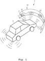
- a first embodiment of the inventive measuring system 1 is shown.
- a plurality of radar test panels 10 is arranged in a half-circle shape around a front portion of a vehicle 2.
- the vehicle 2 comprises several vehicular radars 3.
- Each of the vehicular radars 3 emits radar radiation, which hits one or more of the plurality of radar test panels 10.
- the radar test panels 10 each comprise a 2D radar test array of radar receivers, which receive the radar radiation from the vehicular radar and emit visual light based upon the received radar radiation.
- the emitted light is shown here as a measured beam pattern 12.
- a reference marking 11 is shown here.
- the reference marking 11 shows areas in which radar radiation is expected and areas in which no radar radiation is expected. In this example, radio radiation is expected below the reference marking 11, while no radio radiation is expected above the reference marking 11. This makes it very simple for an operator of the system to determine if the vehicular radar is adjusted properly or not.
- the present invention is not limited to this embodiment. Also, different shapes, like a half-ellipse shape or a U-shape, are possible. Also, a use of only one or two panels is possible. With regard to the arrangement of the radar test panels, it is referred to the later elaborations regarding Fig. 2 and Fig. 3 . With regard to the construction of individual panels, it is referred to the later elaborations regarding Fig. 4 . With regard to the construction of individual radar receivers, it is referred to the later elaborations regarding Fig. 5 .
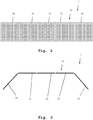
- a second embodiment of the inventive measuring system 1 is shown.
- the radar test panels 20 to 24 are arranged side-by-side. In the embodiment shown here, the radar test panels 20 to 24 are arranged in a straight line, seen from on top.
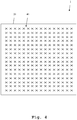
- a third embodiment of the inventive measuring system 1 is shown.
- a top-view of radar test panels 20 to 24 is shown.
- the radar test panels 20 and 24 are arranged at an angle ⁇ 180°, for example at an angle of 120° with regard to the respectively neighboring radar test panel 21/23.
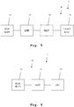
- Fig. 4 a detailed view of a single radar test panel 20 is shown.
- the radar test panel 20 comprises a 2D radar test array of radar receivers 40.
- Each radar receiver 40 is therein configured to individually receive radar radiation emitted by the vehicular radar, and emit visible light based upon the received radar radiation. Further details of individual radar receivers are shown in Fig. 5 .
- the 2D radar test array of radar receivers comprises 16x16 radar receivers 40.
- the radar test panel 20 can comprise for example 2-100, preferably 10-50 radar receivers on the x-axis.
- the radar test panel 20 can comprise 2-100, preferably 10-50 radar receivers 40 on the y-axis.
- a further embodiment of the inventive measuring system 1 is shown.
- the radar receiver 40 comprises a radar sensor 50, which comprises for example an antenna and a detector, connected to an amplifier 51, which is again connected to a mapper 52, which is moreover connected to a light emitter 53.
- the mapper 52 only constitutes an optional component, here. In case the mapper 52 is not present, the amplifier 51 is directly connected to the light emitter 53.
- the radar sensor 50 receives radar radiation from the vehicular radar under test and generates a received radar signal, which is handed to the amplifier 51.
- the amplifier 51 amplifies the received radar signal resulting in an amplified signal.
- the amplified signal is handed to the light emitter 53, if no mapper 52 is present.
- the light emitter 53 in this case emits light of a pre-specified brightness and/or color, if the amplified signal exceeds a threshold, and does not emit light if the amplified signal does not exceed the threshold.
- the amplified signal is handed to the mapper 52, which maps a signal strength of the amplified signal onto a color and/or brightness to be emitted by the light emitter 53.
- the mapper 52 then hands on the respective color and/or brightness, at which the light emitter 53 is to emit light. Finally, the light emitter 53 then emits light at the color and/or brightness determined by the mapper 52.
- the mapper 52 could map a signal strength of the amplified radar signal below a pre-specified threshold to no light emission, map a signal strength above the threshold to a brightness proportional to the amount, by which the threshold is exceeded, and map the color to a color temperature proportional to the amount, by which the threshold is exceeded.
- the radar receiver 40 can either operate completely analog, as shown in Fig. 5 , or can operate in a digital manner. In the latter case, a digitizer is added. Such an alternative radar receiver 40 is shown in Fig. 6 .
- a further embodiment of the inventive measuring system 1 is shown.
- a detail view of one of the radar receivers 40 is shown.
- the radar receiver 40 shown here does not comprise a light emitter, but merely comprises a digitizer 70 directly connected to the amplifier 51.
- the digitizer digitizes the amplified signal and passes it on, for example to a readout interface 60 as shown in Fig. 7 .
- the digitizer 70 can also be added to the embodiment of Fig. 5 , making it compatible to the readout interface 60 of Fig. 7 . This digitizer would then be added between the amplifier 51 and the light emitter 53. In case of the presence of the optional mapper 52, either before or after the mapper 52.
- Fig. 7 a further embodiment of the inventive measuring system 1 is shown.
- the measuring system comprises a readout interface 60 connected to at least one radar test panel 20.
- This embodiment requires the radar receivers 40 to produce digital output signals. Therefore, the radar receivers then each comprise a digitizer, as mentioned earlier.
- the readout interface 60 is therein configured to readout a measured radiation pattern of the vehicular radar, formed by radar signal strengths measured by each of the radar receivers, and to provide the read out measured radiation pattern of the vehicular radar as a digital measured radiation pattern.
- This digital measured radiation pattern can for example be processed further by a software.
- this measured radiation pattern can be displayed on an optional display 63, which is then connected to the readout interface 60.
- This display may also be a display of a personal computer.
- the readout interface 60 can be connected to a comparer 61, which in turn is connected to a reference storage 62.
- the reference storage 62 stores at least one reference radiation pattern, which is readout from the reference storage 62, by the comparer 61.
- the comparer 61 performs a comparison of the digital measured radiation pattern and the reference radiation pattern, resulting in a measuring result.
- the measuring result therein can either be a logical pass or fail decision.
- the comparison result can be a difference signal between the digital measured radiation pattern and the reference radiation pattern.
- This comparison result can then additionally be displayed on the display 63.
- the comparison result can also be displayed on the radar test panels 10 by using the light emitters 53 of the radar receivers 40.
- comparer 61 the reference storage 62 and the display may be implemented as components of a personal computer. Also an implementation of the optional mapper 52 as a component of a personal computer is possible. The mapper 52 and the comparer 61 may also be implemented as software run by a personal computer.
- a first step 100 at least one radar test panel is arranged in an expected radiation direction of a vehicular radar under test.
- a radar signal is emitted by the vehicular radar under test.
- a radar radiation is received from the vehicular radar, by a plurality of radar receivers comprised by the radar test panel.
- a measured beam pattern of the vehicular radar is displayed by emitting visible light based upon the received radar radiation, by the plurality of radar receivers.
- inventive measuring system and inventive measuring method very closely correspond to each other. Therefore, all elaborations regarding the features of the different embodiments of the inventive measuring system are to be understood as disclosed in conjunction with the inventive measuring method as well.
- the invention is not limited to the examples and especially not to specific numbers of radar receivers, types of radar sensors, types of light emitters, etc..
- the invention is not limited to specific types of vehicles carrying the vehicular radar.
- the vehicle can be land based vehicle, like automobiles, motorcycles, bicycles, all terrain vehicles, etc..
- the vehicles can be air based vehicles, like airplanes, helicopters, drones, etc.. Even sea based vehicles, like ships, etc.. are possible.
- the characteristics of the exemplary embodiments can be used in any advantageous combination.
Landscapes
- Engineering & Computer Science (AREA)
- Radar, Positioning & Navigation (AREA)
- Remote Sensing (AREA)
- Computer Networks & Wireless Communication (AREA)
- Physics & Mathematics (AREA)
- General Physics & Mathematics (AREA)
- Radar Systems Or Details Thereof (AREA)
Abstract
Description
- The invention relates to measuring and visualizing the radiation pattern of a vehicular radar, preferably mounted in a vehicle.
- For measuring the radiation pattern of radar devices, usually complex setups having a moveable test antenna and complicated measuring hardware are necessary. These setups require highly trained personnel to perform measurements on the radar devices. This is feasible in a lab environment or in a production environment, but not in a garage environment for servicing vehicles. For example,
US 2019/0391233 A1 shows such a complicated to operate system for testing vehicular radars. - Accordingly, an object of the invention is to provide a system and a method, which allow for a testing of a vehicular radar and which at the same time do not require highly skilled personnel and which are applicable in a garage surrounding.
- The object is solved by the features of the independent claims. Additional features of the invention are provided in the dependent claims. In the following, parts of the description and drawings referring to embodiments, which are not covered by the claims, are not presented as embodiments of the invention, but as examples useful for understanding the invention.
- An inventive measuring system serves the purpose of testing a beam pattern of a vehicular radar. The measuring system comprises at least one radar test panel, which is arranged in an expected radiation direction of the vehicular radar. Each of the at least one radar test panels comprises a 2D radar test array of radar receivers. The at least one radar test panel is therein configured to display a measured beam pattern of the vehicular radar, using the radar receivers. Alternatively, the at least one radar test panel is configured to output a digitized measured beam pattern of the vehicular radar. This allows for a very simple implementation in a workshop environment and does not require a great deal of operator skill.
- It may be noted that the radar receivers are configured to not only perform a receiving, but also at least some processing and/or displaying of information.
- Preferably, each of the radio receivers is configured to receive radar radiation from the vehicular radar and emit visible light based upon the received radar radiation. The radar receivers therefore form pixels and directly show where radar radiation from the vehicular radar actually hits the radar test panel. This allows for a very intuitive operation by personnel of low training level. Also, the system can be used in a garage setup, since no moving test antennas or sensitive measuring devices are required.
- Preferably, the measuring system comprises at least two radar test panels, which are preferably arranged side-by-side. This allows for an enlargement of a testing area, and thereby of an angle under investigation around the radar under test.
- Preferably, the at least two radar test panels are arranged in an angle smaller than 180° with regard to each other. This allows for minimizing the footprint of the measuring system while at the same time allowing for measuring of a larger angle around the vehicle.
- Advantageously and preferably, the system comprises a plurality of radar test panels, which are arranged in a half-circle or half-ellipse or U-shape, encompassing at least part of a vehicle comprising the vehicular radar under test. Alternatively, the plurality of radar test panels are arranged in any shape surrounding the entire vehicle. This allows for an especially small footprint of the resulting system, while at the same time achieving a testing capability of a large angle around the vehicle.
- Preferably, the radar receivers comprises a radar receiver, which is configured to receive the radar radiation from the vehicular radar, an amplifier configured to amplify the received radar signal, and a light emitter configured to emit the visible light based upon the amplified received radar signal. This allows for a very simple and self-contained construction of the measuring system.
- Advantageously and preferably, the light emitter comprises at least one LED, preferably and RGB-LED. This allows for a low power visualization while at the same time allowing for a high information density.
- Preferably, the light emitter is configured to emit light of a pre-specified brightness and/or color if the amplified signal exceeds a threshold. This allows for a very simple construction of the system while achieving an especially easy to interpret result of the measurement.
- Alternatively, the radar receivers each comprise a mapper, which is configured to map a signal strength of the amplified received radar signal to a color and/or brightness of visible light to be emitted by the light emitter. The light emitter is then configured to emit light of the color and/or brightness determined by the mapper. This allows for a significant increase in the information density.
- Preferably, the at least one radar test panel comprises a reference marking showing a shape of a reference radiation pattern. Such a reference marking can, for example, be a line, preferably a colored line, drawn on the radar test panel showing areas where the radio receivers are supposed to light up due to radar radiation hitting it in these areas, and areas, which are not supposed to light up. This allows for an especially simple interpretation of the results by a low-skill worker.
- Preferably, each of the radar receivers comprises a digitizer, configured to digitize a signal generated from radar radiation emitted by the vehicular radar and received by the radar receiver, resulting in a digital received radar signal. The measuring system then additionally comprises a readout interface connected to each of digitizers of the radar receivers, configured to read out a digitized measured radiation pattern of the vehicular radar, formed by the digital received radar signals.
- Moreover, the readout interface is configured to provide the read out measured radiation pattern of the vehicular radar as a digital measured radiation pattern. This allows for a simple further processing of the measured radiation pattern.
- Preferably, the measuring system additionally comprises a reference storage configured to store a digital reference radiation pattern for at least one vehicular radar type. This allows for tracking a compliance of the measured radiation pattern in comparison to the stored pattern.
- Preferably, the measuring system additionally comprises a comparer configured to compare the digital measured radiation pattern to the stored radiation pattern generating a comparison result. By automatically determining the comparison result, the requirements regarding the skill level of the operator can be further reduced.
- Advantageously and preferably, the at least one radar test panel is configured to display the at least one reference radiation pattern and/or the comparison result before and/or after and/or while displaying the measured beam pattern of the vehicular radar using the 2D radar test array of radar receivers. This allows for displaying results without the use of need of an additional display device. This results in a very low hardware complexity and a very robust construction of the entire measuring system.
- Alternatively or additionally, the measuring system comprises a display, which is configured to display the digital measured radiation pattern and/or the reference radiation pattern and/or the comparison result. This allows for an even more accurate display of the results.
- An inventive measuring method serves the purpose of testing a beam pattern of a vehicular radar. The method comprises arranging at least one radar test panel in an expected radiation direction of a vehicular radar, emitting a radar signal by the vehicular radar, receiving radar radiation from the vehicular radar by a plurality of radio receivers comprised by the at least one radar test panel, and displaying a measured beam pattern of the vehicular radar by emitting visible light based upon the received radar radiation by the plurality of radar receivers. Alternatively, the method comprises outputting a digitized measured beam pattern of the vehicular radar. This allows for a very simple implementation in a workshop environment and does not require a great deal of operator skill.
- Exemplary embodiments of the invention are now further explained with regard to the drawings, in which
- Fig. 1
- shows a first embodiment of the inventive measuring system;
- Fig. 2
- shows a second embodiment of the inventive measuring system in a detail view;
- Fig. 3
- shows a third embodiment of the inventive measuring system in a detail view;
- Fig. 4
- shows a fourth embodiment of the inventive measuring system in a detail view showing the inner construction of a radar test panel;
- Fig. 5
- shows a fifth embodiment of the inventive system showing a detail view of a radar receiver in a block diagram;
- Fig. 6
- shows a sixth embodiment of the inventive system in a detail view;
- Fig. 7
- shows a seventh embodiment of the inventive system in a detail view, and
- Fig. 8
- shows an embodiment of the inventive measuring method.
- First, we demonstrate the general construction and function of an embodiment of the inventive measuring system along
Fig. 1 . With regard toFig. 2 to Fig. 7 , further construction details and functions of different embodiments of inventive measuring system are shown and described. Finally, alongFig. 8 , the function of an embodiment of an inventive measuring method is described in detail. Similar entities and reference numbers in different Figures have been partially omitted. - In
Fig. 1 , a first embodiment of theinventive measuring system 1 is shown. Here, a plurality ofradar test panels 10 is arranged in a half-circle shape around a front portion of a vehicle 2. The vehicle 2 comprises several vehicular radars 3. Each of the vehicular radars 3 emits radar radiation, which hits one or more of the plurality ofradar test panels 10. Theradar test panels 10 each comprise a 2D radar test array of radar receivers, which receive the radar radiation from the vehicular radar and emit visual light based upon the received radar radiation. The emitted light is shown here as a measuredbeam pattern 12. Additionally, a reference marking 11 is shown here. The reference marking 11 shows areas in which radar radiation is expected and areas in which no radar radiation is expected. In this example, radio radiation is expected below the reference marking 11, while no radio radiation is expected above the reference marking 11. This makes it very simple for an operator of the system to determine if the vehicular radar is adjusted properly or not. - It is important to note that, although here a plurality of
radar test panels 10 in a half-circle shape around a front portion of the vehicle are shown, the present invention is not limited to this embodiment. Also, different shapes, like a half-ellipse shape or a U-shape, are possible. Also, a use of only one or two panels is possible. With regard to the arrangement of the radar test panels, it is referred to the later elaborations regardingFig. 2 and Fig. 3 . With regard to the construction of individual panels, it is referred to the later elaborations regardingFig. 4 . With regard to the construction of individual radar receivers, it is referred to the later elaborations regardingFig. 5 . - In
Fig. 2 , a second embodiment of theinventive measuring system 1 is shown. Here, only theradar panels radar test panels 10, are shown. Theradar test panels 20 to 24 are arranged side-by-side. In the embodiment shown here, theradar test panels 20 to 24 are arranged in a straight line, seen from on top. - In
Fig. 3 , a third embodiment of theinventive measuring system 1 is shown. Here, a top-view ofradar test panels 20 to 24 is shown. Here, theradar test panels radar test panel 21/23. - In
Fig. 4 , a detailed view of a singleradar test panel 20 is shown. Here, it is easily visible that theradar test panel 20 comprises a 2D radar test array ofradar receivers 40. Eachradar receiver 40 is therein configured to individually receive radar radiation emitted by the vehicular radar, and emit visible light based upon the received radar radiation. Further details of individual radar receivers are shown inFig. 5 . - In the embodiment of
Fig. 4 , the 2D radar test array of radar receivers comprises16x16 radar receivers 40. The invention though is not delimited to this specific number. In practice, theradar test panel 20 can comprise for example 2-100, preferably 10-50 radar receivers on the x-axis. Moreover, in practice theradar test panel 20 can comprise 2-100, preferably 10-50radar receivers 40 on the y-axis. - In
Fig. 5 , a further embodiment of theinventive measuring system 1 is shown. Here, the inner construction of asingle radar receiver 40 is shown. Theradar receiver 40 comprises aradar sensor 50, which comprises for example an antenna and a detector, connected to anamplifier 51, which is again connected to amapper 52, which is moreover connected to alight emitter 53. It is important to note that themapper 52 only constitutes an optional component, here. In case themapper 52 is not present, theamplifier 51 is directly connected to thelight emitter 53. - In operation, the
radar sensor 50 receives radar radiation from the vehicular radar under test and generates a received radar signal, which is handed to theamplifier 51. Theamplifier 51 amplifies the received radar signal resulting in an amplified signal. The amplified signal is handed to thelight emitter 53, if nomapper 52 is present. Thelight emitter 53 in this case emits light of a pre-specified brightness and/or color, if the amplified signal exceeds a threshold, and does not emit light if the amplified signal does not exceed the threshold. - Alternatively, if the
mapper 52 is present, the amplified signal is handed to themapper 52, which maps a signal strength of the amplified signal onto a color and/or brightness to be emitted by thelight emitter 53. Themapper 52 then hands on the respective color and/or brightness, at which thelight emitter 53 is to emit light. Finally, thelight emitter 53 then emits light at the color and/or brightness determined by themapper 52. - For example, the
mapper 52 could map a signal strength of the amplified radar signal below a pre-specified threshold to no light emission, map a signal strength above the threshold to a brightness proportional to the amount, by which the threshold is exceeded, and map the color to a color temperature proportional to the amount, by which the threshold is exceeded. - It should be pointed out that the
radar receiver 40 can either operate completely analog, as shown inFig. 5 , or can operate in a digital manner. In the latter case, a digitizer is added. Such analternative radar receiver 40 is shown inFig. 6 . - In
Fig. 6 , a further embodiment of theinventive measuring system 1 is shown. Here a detail view of one of theradar receivers 40 is shown. Theradar receiver 40 shown here does not comprise a light emitter, but merely comprises adigitizer 70 directly connected to theamplifier 51. - The digitizer digitizes the amplified signal and passes it on, for example to a
readout interface 60 as shown inFig. 7 . - It should be pointed out that the
digitizer 70 can also be added to the embodiment ofFig. 5 , making it compatible to thereadout interface 60 ofFig. 7 . This digitizer would then be added between theamplifier 51 and thelight emitter 53. In case of the presence of theoptional mapper 52, either before or after themapper 52. - In
Fig. 7 a further embodiment of theinventive measuring system 1 is shown. Here the measuring system comprises areadout interface 60 connected to at least oneradar test panel 20. This embodiment requires theradar receivers 40 to produce digital output signals. Therefore, the radar receivers then each comprise a digitizer, as mentioned earlier. - The
readout interface 60 is therein configured to readout a measured radiation pattern of the vehicular radar, formed by radar signal strengths measured by each of the radar receivers, and to provide the read out measured radiation pattern of the vehicular radar as a digital measured radiation pattern. This digital measured radiation pattern can for example be processed further by a software. Alternatively, this measured radiation pattern can be displayed on anoptional display 63, which is then connected to thereadout interface 60. This display may also be a display of a personal computer.
In a further optional development, thereadout interface 60 can be connected to acomparer 61, which in turn is connected to areference storage 62. Thereference storage 62 stores at least one reference radiation pattern, which is readout from thereference storage 62, by thecomparer 61. Thecomparer 61 performs a comparison of the digital measured radiation pattern and the reference radiation pattern, resulting in a measuring result. The measuring result therein can either be a logical pass or fail decision. Alternatively, the comparison result can be a difference signal between the digital measured radiation pattern and the reference radiation pattern. This comparison result can then additionally be displayed on thedisplay 63. Alternatively, the comparison result can also be displayed on theradar test panels 10 by using thelight emitters 53 of theradar receivers 40. - It should be pointed out that the
comparer 61, thereference storage 62 and the display may be implemented as components of a personal computer. Also an implementation of theoptional mapper 52 as a component of a personal computer is possible. Themapper 52 and thecomparer 61 may also be implemented as software run by a personal computer. - Finally, in
Fig. 8 , an embodiment of the inventive measuring method is shown. In afirst step 100, at least one radar test panel is arranged in an expected radiation direction of a vehicular radar under test. In asecond step 101, a radar signal is emitted by the vehicular radar under test. In athird step 102, radar radiation is received from the vehicular radar, by a plurality of radar receivers comprised by the radar test panel. In a finalfourth step 103, a measured beam pattern of the vehicular radar is displayed by emitting visible light based upon the received radar radiation, by the plurality of radar receivers. - It is important to note that the inventive measuring system and inventive measuring method very closely correspond to each other. Therefore, all elaborations regarding the features of the different embodiments of the inventive measuring system are to be understood as disclosed in conjunction with the inventive measuring method as well.
- The invention is not limited to the examples and especially not to specific numbers of radar receivers, types of radar sensors, types of light emitters, etc.. Especially, the invention is not limited to specific types of vehicles carrying the vehicular radar. The vehicle can be land based vehicle, like automobiles, motorcycles, bicycles, all terrain vehicles, etc.. Also the vehicles can be air based vehicles, like airplanes, helicopters, drones, etc.. Even sea based vehicles, like ships, etc.. are possible. The characteristics of the exemplary embodiments can be used in any advantageous combination.
Claims (15)
- Measuring system (1) for testing a beam pattern of a vehicular radar (3),
comprising at least one radar test panel (10, 20, 21, 22, 23, 24), arranged in an expected radiation direction of the vehicular radar (3),
wherein each of the at least one radar test panels (10, 20, 21, 22, 23, 24) comprises a two-dimensional radar test array of radar receivers (40),
wherein the at least one radar test panel (10, 20, 21, 22, 23, 24) is configured to display a measured beam pattern (12) of the vehicular radar (3), using the radar receivers (40), or
wherein the at least one radar test panel (10, 20, 21, 22, 23, 24) is configured to output a digitized measured beam pattern (12) of the vehicular radar (3). - Measuring system (1) according to claim 1,
wherein each of the radar receivers (40) is configured to- receive radar radiation from the vehicular radar (3), and- emit visible light based upon the received radar radiation. - Measuring system (1) according to claim 1 or 2, comprising at least two radar test panels (10, 20, 21, 22, 23, 24), preferably arranged side-by-side,
wherein the at least two radar test panels (10, 20, 21, 22, 23, 24) are arranged in an angle smaller than 180° with regard to each other. - Measuring system (1) according to claim 1 or 2, comprising a plurality of radar test panels (10, 20, 21, 22, 23, 24), arranged- in a half-circle or half-ellipse or U-shape, encompassing at least part of a vehicle (2) comprising the vehicular radar (3), or- in any shape surrounding the entire vehicle (2).
- Measuring system (1) according to any of the claims 1 to 4,
wherein each of the radar receivers (40) comprises- a radar receiver (50), configured to receive the radar radiation from the vehicular radar (3),- an amplifier (51), configured to amplify the received radar signal, and- a light emitter (53), configured to emit the visible light based upon the amplified received radar signal. - Measuring system (1) according to claim 5,
wherein the light emitter (53) comprises at least one light emitting diode LED, preferably an RGB-LED. - Measuring system (1) according to claim 5 or 6,
wherein the light emitter (53) is configured to emit light of a pre-specified brightness and/or color, if the amplified radar signal exceeds a threshold. - Measuring system (1) according to claim 5 or 6,
wherein each of the radar receivers (40) comprises a mapper (52), configured to map a signal strength of the amplified received radar signal to a color and/or brightness of visible light to be emitted by the light emitter, and
wherein the light emitter (53) is configured to emit light of the color and/or brightness determined by the mapper (52) . - Measuring system (1) according to any of claims 1 to 8,
wherein the at least one radar test panel (10, 20, 21, 22, 23, 24) comprises a reference marking (11), showing a shape of a reference radiation pattern. - Measuring system (1) according to any of claims 1 to 9,
wherein each of the radar receivers (40) comprises a digitizer (70), configured to digitize a signal generated from radar radiation emitted by the vehicular radar and received by the radar receiver (40), resulting in a digital received radar signal,
comprising a readout interface (60), connected to the digitizer (70) of each of the radar receivers (40), configured to read out a digital measured radiation pattern of the vehicular radar (3), formed by the digital received radar signals. - Measuring system (1) according to claims 10, comprising a reference storage (62), configured to store a digital reference radiation pattern for at least one vehicular radar (3) type.
- Measuring system (1) according to claim 11, comprising a reference comparer (61), configured to compare the digital measured radiation pattern to the stored reference radiation pattern, generating a comparison result.
- Measuring system (1) according to claim 11 or 12,
wherein the at least one radar test panel (10, 20, 21, 22, 23, 24) is configured to display the at least one reference radiation pattern and/or the comparison result before and/or after and/or while displaying the measured beam pattern of the vehicular radar (3), using the 2D radar test array of radar receivers (40). - Measuring system (1) according to any of claims 10 to 13,
comprising a display (63), configured to display the digital measured radiation pattern and/or the reference radiation pattern and/or the comparison result. - Measuring method for testing a beam pattern of a vehicular radar (3),
with the the following steps:- arranging (100) at least one radar test panel (10, 20, 21, 22, 23, 24) in an expected radiation direction of the vehicular radar (3),- emitting (101) a radar signal by the vehicular radar (3),- receiving (102) radar radiation from the vehicular radar (3) by a plurality of radar receivers (40) comprised by the at least one radar test panel (10, 20, 21, 22, 23, 24), and- displaying (103) a measured beam pattern of the vehicular radar (3), by emitting visible light based upon the received radar radiation, by the plurality of radar receivers (40), or- outputting a digitized measured beam pattern (12) of the vehicular radar (3).
Priority Applications (1)
| Application Number | Priority Date | Filing Date | Title |
|---|---|---|---|
| EP20180420.0A EP3926359B1 (en) | 2020-06-17 | 2020-06-17 | System and method for testing a beam pattern of a vehicular radar |
Applications Claiming Priority (1)
| Application Number | Priority Date | Filing Date | Title |
|---|---|---|---|
| EP20180420.0A EP3926359B1 (en) | 2020-06-17 | 2020-06-17 | System and method for testing a beam pattern of a vehicular radar |
Publications (2)
| Publication Number | Publication Date |
|---|---|
| EP3926359A1 true EP3926359A1 (en) | 2021-12-22 |
| EP3926359B1 EP3926359B1 (en) | 2024-08-28 |
Family
ID=71105319
Family Applications (1)
| Application Number | Title | Priority Date | Filing Date |
|---|---|---|---|
| EP20180420.0A Active EP3926359B1 (en) | 2020-06-17 | 2020-06-17 | System and method for testing a beam pattern of a vehicular radar |
Country Status (1)
| Country | Link |
|---|---|
| EP (1) | EP3926359B1 (en) |
Citations (5)
| Publication number | Priority date | Publication date | Assignee | Title |
|---|---|---|---|---|
| WO2010058194A1 (en) * | 2008-11-20 | 2010-05-27 | Mbda Uk Limited | Target scene generator |
| DE102009038907A1 (en) * | 2009-08-26 | 2011-03-03 | Daimler Ag | Method for adjusting orientation of radiation characteristic of radar sensor, particularly distance radar, of vehicle, involves positioning radar detector array in predetermined distance from radar sensor |
| DE102018208464A1 (en) * | 2018-05-29 | 2019-12-05 | Fraunhofer-Gesellschaft zur Förderung der angewandten Forschung e.V. | Method for functional testing of a radar sensor and device suitable for carrying out the method |
| US20190391233A1 (en) | 2018-06-25 | 2019-12-26 | Hyundai Motor Company | System and method for vehicle radar inspection |
| US20200136263A1 (en) * | 2018-10-29 | 2020-04-30 | Keysight Technologies, Inc. | Millimeter-wave detect or reflect array |
-
2020
- 2020-06-17 EP EP20180420.0A patent/EP3926359B1/en active Active
Patent Citations (5)
| Publication number | Priority date | Publication date | Assignee | Title |
|---|---|---|---|---|
| WO2010058194A1 (en) * | 2008-11-20 | 2010-05-27 | Mbda Uk Limited | Target scene generator |
| DE102009038907A1 (en) * | 2009-08-26 | 2011-03-03 | Daimler Ag | Method for adjusting orientation of radiation characteristic of radar sensor, particularly distance radar, of vehicle, involves positioning radar detector array in predetermined distance from radar sensor |
| DE102018208464A1 (en) * | 2018-05-29 | 2019-12-05 | Fraunhofer-Gesellschaft zur Förderung der angewandten Forschung e.V. | Method for functional testing of a radar sensor and device suitable for carrying out the method |
| US20190391233A1 (en) | 2018-06-25 | 2019-12-26 | Hyundai Motor Company | System and method for vehicle radar inspection |
| US20200136263A1 (en) * | 2018-10-29 | 2020-04-30 | Keysight Technologies, Inc. | Millimeter-wave detect or reflect array |
Also Published As
| Publication number | Publication date |
|---|---|
| EP3926359B1 (en) | 2024-08-28 |
Similar Documents
| Publication | Publication Date | Title |
|---|---|---|
| CN101476844B (en) | Calibration method and standard target plate for carrier optoelectronic series on-site dynamic self-calibration | |
| KR100566827B1 (en) | Method of acquiring and displaying a radiometric image of an object and the system using the same | |
| CN107976657A (en) | Radar calibration is carried out using the known global location of stationary objects | |
| CN113624374B (en) | Bridge inhaul cable group cable force synchronous monitoring system and method based on microwave full-field sensing | |
| WO2023183659A1 (en) | Method, platform, and system of electromagnetic marking of objects and environments for augmented reality | |
| CN104749577A (en) | Laser Radar Device And Object Detection Method | |
| US6987571B2 (en) | Sensor head, luminance distribution measurement apparatus having the sensor head, and unevenness inspection/evaluation apparatus | |
| CN112748417B (en) | Laser radar control method and device, electronic equipment and storage medium | |
| CN113133319A (en) | Calibration plate, method and device for testing angular resolution and computer storage medium | |
| EP3441785B1 (en) | System and method for tracking a sling load and terrain with a radar altimeter | |
| EP3926359B1 (en) | System and method for testing a beam pattern of a vehicular radar | |
| Malanowski et al. | Passive location system as a combination of PCL and PET technologies | |
| US11899124B2 (en) | Interface for realtime, 3D radar activity visualization | |
| CN115079141A (en) | Test system and method for laser radar sensor | |
| De Buizer et al. | Surveying the Giant H ii Regions of the Milky Way with SOFIA. III. W49A | |
| US20080259312A1 (en) | Range and Velocity Sensing System | |
| EP3772642B1 (en) | Characterization of aerosols | |
| RU166885U1 (en) | RADAR FOR ANALYSIS OF HELICOPTER LANDING PLACE | |
| CN106164696B (en) | close to the device | |
| US20260003062A1 (en) | Id tag and detecting system | |
| CN214585992U (en) | Photon radar for full-airspace real-time detection | |
| CN215217577U (en) | 3D structured light measuring device | |
| RU2596628C1 (en) | Method of determining contamination of sea surface | |
| CN118837841A (en) | Radar target angle measurement method, radar target angle measurement device and storage medium | |
| US4045140A (en) | Means for near real time C-W laser source characterization |
Legal Events
| Date | Code | Title | Description |
|---|---|---|---|
| PUAI | Public reference made under article 153(3) epc to a published international application that has entered the european phase |
Free format text: ORIGINAL CODE: 0009012 |
|
| STAA | Information on the status of an ep patent application or granted ep patent |
Free format text: STATUS: REQUEST FOR EXAMINATION WAS MADE |
|
| 17P | Request for examination filed |
Effective date: 20210311 |
|
| AK | Designated contracting states |
Kind code of ref document: A1 Designated state(s): AL AT BE BG CH CY CZ DE DK EE ES FI FR GB GR HR HU IE IS IT LI LT LU LV MC MK MT NL NO PL PT RO RS SE SI SK SM TR |
|
| B565 | Issuance of search results under rule 164(2) epc |
Effective date: 20201203 |
|
| STAA | Information on the status of an ep patent application or granted ep patent |
Free format text: STATUS: EXAMINATION IS IN PROGRESS |
|
| 17Q | First examination report despatched |
Effective date: 20230313 |
|
| P01 | Opt-out of the competence of the unified patent court (upc) registered |
Effective date: 20230525 |
|
| GRAP | Despatch of communication of intention to grant a patent |
Free format text: ORIGINAL CODE: EPIDOSNIGR1 |
|
| STAA | Information on the status of an ep patent application or granted ep patent |
Free format text: STATUS: GRANT OF PATENT IS INTENDED |
|
| INTG | Intention to grant announced |
Effective date: 20240305 |
|
| GRAS | Grant fee paid |
Free format text: ORIGINAL CODE: EPIDOSNIGR3 |
|
| GRAA | (expected) grant |
Free format text: ORIGINAL CODE: 0009210 |
|
| STAA | Information on the status of an ep patent application or granted ep patent |
Free format text: STATUS: THE PATENT HAS BEEN GRANTED |
|
| RBV | Designated contracting states (corrected) |
Designated state(s): AL AT BE BG CY CZ DE DK EE ES FI FR GB GR HR HU IS IT LT LU LV MC MK MT NL NO PL PT RO RS SE SI SK SM TR |
|
| AK | Designated contracting states |
Kind code of ref document: B1 Designated state(s): AL AT BE BG CY CZ DE DK EE ES FI FR GB GR HR HU IS IT LT LU LV MC MK MT NL NO PL PT RO RS SE SI SK SM TR |
|
| REG | Reference to a national code |
Ref country code: DE Ref legal event code: R096 Ref document number: 602020036524 Country of ref document: DE |
|
| REG | Reference to a national code |
Ref country code: LT Ref legal event code: MG9D |
|
| PG25 | Lapsed in a contracting state [announced via postgrant information from national office to epo] |
Ref country code: NO Free format text: LAPSE BECAUSE OF FAILURE TO SUBMIT A TRANSLATION OF THE DESCRIPTION OR TO PAY THE FEE WITHIN THE PRESCRIBED TIME-LIMIT Effective date: 20241128 |
|
| REG | Reference to a national code |
Ref country code: AT Ref legal event code: MK05 Ref document number: 1718545 Country of ref document: AT Kind code of ref document: T Effective date: 20240828 |
|
| PG25 | Lapsed in a contracting state [announced via postgrant information from national office to epo] |
Ref country code: NL Free format text: LAPSE BECAUSE OF FAILURE TO SUBMIT A TRANSLATION OF THE DESCRIPTION OR TO PAY THE FEE WITHIN THE PRESCRIBED TIME-LIMIT Effective date: 20240828 Ref country code: PT Free format text: LAPSE BECAUSE OF FAILURE TO SUBMIT A TRANSLATION OF THE DESCRIPTION OR TO PAY THE FEE WITHIN THE PRESCRIBED TIME-LIMIT Effective date: 20241230 Ref country code: FI Free format text: LAPSE BECAUSE OF FAILURE TO SUBMIT A TRANSLATION OF THE DESCRIPTION OR TO PAY THE FEE WITHIN THE PRESCRIBED TIME-LIMIT Effective date: 20240828 Ref country code: GR Free format text: LAPSE BECAUSE OF FAILURE TO SUBMIT A TRANSLATION OF THE DESCRIPTION OR TO PAY THE FEE WITHIN THE PRESCRIBED TIME-LIMIT Effective date: 20241129 Ref country code: PL Free format text: LAPSE BECAUSE OF FAILURE TO SUBMIT A TRANSLATION OF THE DESCRIPTION OR TO PAY THE FEE WITHIN THE PRESCRIBED TIME-LIMIT Effective date: 20240828 |
|
| PG25 | Lapsed in a contracting state [announced via postgrant information from national office to epo] |
Ref country code: BG Free format text: LAPSE BECAUSE OF FAILURE TO SUBMIT A TRANSLATION OF THE DESCRIPTION OR TO PAY THE FEE WITHIN THE PRESCRIBED TIME-LIMIT Effective date: 20240828 |
|
| PG25 | Lapsed in a contracting state [announced via postgrant information from national office to epo] |
Ref country code: LV Free format text: LAPSE BECAUSE OF FAILURE TO SUBMIT A TRANSLATION OF THE DESCRIPTION OR TO PAY THE FEE WITHIN THE PRESCRIBED TIME-LIMIT Effective date: 20240828 |
|
| REG | Reference to a national code |
Ref country code: NL Ref legal event code: MP Effective date: 20240828 |
|
| PG25 | Lapsed in a contracting state [announced via postgrant information from national office to epo] |
Ref country code: AT Free format text: LAPSE BECAUSE OF FAILURE TO SUBMIT A TRANSLATION OF THE DESCRIPTION OR TO PAY THE FEE WITHIN THE PRESCRIBED TIME-LIMIT Effective date: 20240828 Ref country code: IS Free format text: LAPSE BECAUSE OF FAILURE TO SUBMIT A TRANSLATION OF THE DESCRIPTION OR TO PAY THE FEE WITHIN THE PRESCRIBED TIME-LIMIT Effective date: 20241228 |
|
| PG25 | Lapsed in a contracting state [announced via postgrant information from national office to epo] |
Ref country code: HR Free format text: LAPSE BECAUSE OF FAILURE TO SUBMIT A TRANSLATION OF THE DESCRIPTION OR TO PAY THE FEE WITHIN THE PRESCRIBED TIME-LIMIT Effective date: 20240828 |
|
| PG25 | Lapsed in a contracting state [announced via postgrant information from national office to epo] |
Ref country code: RS Free format text: LAPSE BECAUSE OF FAILURE TO SUBMIT A TRANSLATION OF THE DESCRIPTION OR TO PAY THE FEE WITHIN THE PRESCRIBED TIME-LIMIT Effective date: 20241128 Ref country code: ES Free format text: LAPSE BECAUSE OF FAILURE TO SUBMIT A TRANSLATION OF THE DESCRIPTION OR TO PAY THE FEE WITHIN THE PRESCRIBED TIME-LIMIT Effective date: 20240828 |
|
| PG25 | Lapsed in a contracting state [announced via postgrant information from national office to epo] |
Ref country code: RS Free format text: LAPSE BECAUSE OF FAILURE TO SUBMIT A TRANSLATION OF THE DESCRIPTION OR TO PAY THE FEE WITHIN THE PRESCRIBED TIME-LIMIT Effective date: 20241128 Ref country code: PT Free format text: LAPSE BECAUSE OF FAILURE TO SUBMIT A TRANSLATION OF THE DESCRIPTION OR TO PAY THE FEE WITHIN THE PRESCRIBED TIME-LIMIT Effective date: 20241230 Ref country code: PL Free format text: LAPSE BECAUSE OF FAILURE TO SUBMIT A TRANSLATION OF THE DESCRIPTION OR TO PAY THE FEE WITHIN THE PRESCRIBED TIME-LIMIT Effective date: 20240828 Ref country code: NO Free format text: LAPSE BECAUSE OF FAILURE TO SUBMIT A TRANSLATION OF THE DESCRIPTION OR TO PAY THE FEE WITHIN THE PRESCRIBED TIME-LIMIT Effective date: 20241128 Ref country code: NL Free format text: LAPSE BECAUSE OF FAILURE TO SUBMIT A TRANSLATION OF THE DESCRIPTION OR TO PAY THE FEE WITHIN THE PRESCRIBED TIME-LIMIT Effective date: 20240828 Ref country code: LV Free format text: LAPSE BECAUSE OF FAILURE TO SUBMIT A TRANSLATION OF THE DESCRIPTION OR TO PAY THE FEE WITHIN THE PRESCRIBED TIME-LIMIT Effective date: 20240828 Ref country code: IS Free format text: LAPSE BECAUSE OF FAILURE TO SUBMIT A TRANSLATION OF THE DESCRIPTION OR TO PAY THE FEE WITHIN THE PRESCRIBED TIME-LIMIT Effective date: 20241228 Ref country code: HR Free format text: LAPSE BECAUSE OF FAILURE TO SUBMIT A TRANSLATION OF THE DESCRIPTION OR TO PAY THE FEE WITHIN THE PRESCRIBED TIME-LIMIT Effective date: 20240828 Ref country code: GR Free format text: LAPSE BECAUSE OF FAILURE TO SUBMIT A TRANSLATION OF THE DESCRIPTION OR TO PAY THE FEE WITHIN THE PRESCRIBED TIME-LIMIT Effective date: 20241129 Ref country code: FI Free format text: LAPSE BECAUSE OF FAILURE TO SUBMIT A TRANSLATION OF THE DESCRIPTION OR TO PAY THE FEE WITHIN THE PRESCRIBED TIME-LIMIT Effective date: 20240828 Ref country code: ES Free format text: LAPSE BECAUSE OF FAILURE TO SUBMIT A TRANSLATION OF THE DESCRIPTION OR TO PAY THE FEE WITHIN THE PRESCRIBED TIME-LIMIT Effective date: 20240828 Ref country code: BG Free format text: LAPSE BECAUSE OF FAILURE TO SUBMIT A TRANSLATION OF THE DESCRIPTION OR TO PAY THE FEE WITHIN THE PRESCRIBED TIME-LIMIT Effective date: 20240828 Ref country code: AT Free format text: LAPSE BECAUSE OF FAILURE TO SUBMIT A TRANSLATION OF THE DESCRIPTION OR TO PAY THE FEE WITHIN THE PRESCRIBED TIME-LIMIT Effective date: 20240828 |
|
| PG25 | Lapsed in a contracting state [announced via postgrant information from national office to epo] |
Ref country code: SM Free format text: LAPSE BECAUSE OF FAILURE TO SUBMIT A TRANSLATION OF THE DESCRIPTION OR TO PAY THE FEE WITHIN THE PRESCRIBED TIME-LIMIT Effective date: 20240828 Ref country code: RO Free format text: LAPSE BECAUSE OF FAILURE TO SUBMIT A TRANSLATION OF THE DESCRIPTION OR TO PAY THE FEE WITHIN THE PRESCRIBED TIME-LIMIT Effective date: 20240828 Ref country code: DK Free format text: LAPSE BECAUSE OF FAILURE TO SUBMIT A TRANSLATION OF THE DESCRIPTION OR TO PAY THE FEE WITHIN THE PRESCRIBED TIME-LIMIT Effective date: 20240828 |
|
| PG25 | Lapsed in a contracting state [announced via postgrant information from national office to epo] |
Ref country code: EE Free format text: LAPSE BECAUSE OF FAILURE TO SUBMIT A TRANSLATION OF THE DESCRIPTION OR TO PAY THE FEE WITHIN THE PRESCRIBED TIME-LIMIT Effective date: 20240828 |
|
| PG25 | Lapsed in a contracting state [announced via postgrant information from national office to epo] |
Ref country code: CZ Free format text: LAPSE BECAUSE OF FAILURE TO SUBMIT A TRANSLATION OF THE DESCRIPTION OR TO PAY THE FEE WITHIN THE PRESCRIBED TIME-LIMIT Effective date: 20240828 |
|
| PG25 | Lapsed in a contracting state [announced via postgrant information from national office to epo] |
Ref country code: IT Free format text: LAPSE BECAUSE OF FAILURE TO SUBMIT A TRANSLATION OF THE DESCRIPTION OR TO PAY THE FEE WITHIN THE PRESCRIBED TIME-LIMIT Effective date: 20240828 Ref country code: SK Free format text: LAPSE BECAUSE OF FAILURE TO SUBMIT A TRANSLATION OF THE DESCRIPTION OR TO PAY THE FEE WITHIN THE PRESCRIBED TIME-LIMIT Effective date: 20240828 |
|
| REG | Reference to a national code |
Ref country code: DE Ref legal event code: R097 Ref document number: 602020036524 Country of ref document: DE |
|
| PLBE | No opposition filed within time limit |
Free format text: ORIGINAL CODE: 0009261 |
|
| STAA | Information on the status of an ep patent application or granted ep patent |
Free format text: STATUS: NO OPPOSITION FILED WITHIN TIME LIMIT |
|
| PGFP | Annual fee paid to national office [announced via postgrant information from national office to epo] |
Ref country code: DE Payment date: 20250618 Year of fee payment: 6 |
|
| PGFP | Annual fee paid to national office [announced via postgrant information from national office to epo] |
Ref country code: GB Payment date: 20250620 Year of fee payment: 6 |
|
| PGFP | Annual fee paid to national office [announced via postgrant information from national office to epo] |
Ref country code: FR Payment date: 20250627 Year of fee payment: 6 |
|
| 26N | No opposition filed |
Effective date: 20250530 |
|
| PG25 | Lapsed in a contracting state [announced via postgrant information from national office to epo] |
Ref country code: SE Free format text: LAPSE BECAUSE OF FAILURE TO SUBMIT A TRANSLATION OF THE DESCRIPTION OR TO PAY THE FEE WITHIN THE PRESCRIBED TIME-LIMIT Effective date: 20240828 |
|
| PG25 | Lapsed in a contracting state [announced via postgrant information from national office to epo] |
Ref country code: MC Free format text: LAPSE BECAUSE OF FAILURE TO SUBMIT A TRANSLATION OF THE DESCRIPTION OR TO PAY THE FEE WITHIN THE PRESCRIBED TIME-LIMIT Effective date: 20240828 |
|
| PG25 | Lapsed in a contracting state [announced via postgrant information from national office to epo] |
Ref country code: LU Free format text: LAPSE BECAUSE OF NON-PAYMENT OF DUE FEES Effective date: 20250617 |
|
| REG | Reference to a national code |
Ref country code: BE Ref legal event code: MM Effective date: 20250630 |
|
| PG25 | Lapsed in a contracting state [announced via postgrant information from national office to epo] |
Ref country code: BE Free format text: LAPSE BECAUSE OF NON-PAYMENT OF DUE FEES Effective date: 20250630 |