EP3926327A1 - Fire extinguishing agent concentration measuring system and method - Google Patents
Fire extinguishing agent concentration measuring system and method Download PDFInfo
- Publication number
- EP3926327A1 EP3926327A1 EP21179845.9A EP21179845A EP3926327A1 EP 3926327 A1 EP3926327 A1 EP 3926327A1 EP 21179845 A EP21179845 A EP 21179845A EP 3926327 A1 EP3926327 A1 EP 3926327A1
- Authority
- EP
- European Patent Office
- Prior art keywords
- fire extinguishing
- window
- tube
- extinguishing agent
- sensing volume
- Prior art date
- Legal status (The legal status is an assumption and is not a legal conclusion. Google has not performed a legal analysis and makes no representation as to the accuracy of the status listed.)
- Granted
Links
Images


Classifications
-
- G—PHYSICS
- G01—MEASURING; TESTING
- G01N—INVESTIGATING OR ANALYSING MATERIALS BY DETERMINING THEIR CHEMICAL OR PHYSICAL PROPERTIES
- G01N21/00—Investigating or analysing materials by the use of optical means, i.e. using sub-millimetre waves, infrared, visible or ultraviolet light
- G01N21/17—Systems in which incident light is modified in accordance with the properties of the material investigated
- G01N21/47—Scattering, i.e. diffuse reflection
- G01N21/49—Scattering, i.e. diffuse reflection within a body or fluid
- G01N21/53—Scattering, i.e. diffuse reflection within a body or fluid within a flowing fluid, e.g. smoke
- G01N21/534—Scattering, i.e. diffuse reflection within a body or fluid within a flowing fluid, e.g. smoke by measuring transmission alone, i.e. determining opacity
-
- G—PHYSICS
- G01—MEASURING; TESTING
- G01N—INVESTIGATING OR ANALYSING MATERIALS BY DETERMINING THEIR CHEMICAL OR PHYSICAL PROPERTIES
- G01N15/00—Investigating characteristics of particles; Investigating permeability, pore-volume or surface-area of porous materials
- G01N15/06—Investigating concentration of particle suspensions
-
- A—HUMAN NECESSITIES
- A62—LIFE-SAVING; FIRE-FIGHTING
- A62C—FIRE-FIGHTING
- A62C37/00—Control of fire-fighting equipment
-
- G—PHYSICS
- G01—MEASURING; TESTING
- G01N—INVESTIGATING OR ANALYSING MATERIALS BY DETERMINING THEIR CHEMICAL OR PHYSICAL PROPERTIES
- G01N21/00—Investigating or analysing materials by the use of optical means, i.e. using sub-millimetre waves, infrared, visible or ultraviolet light
- G01N21/84—Systems specially adapted for particular applications
- G01N21/85—Investigating moving fluids or granular solids
-
- G—PHYSICS
- G01—MEASURING; TESTING
- G01N—INVESTIGATING OR ANALYSING MATERIALS BY DETERMINING THEIR CHEMICAL OR PHYSICAL PROPERTIES
- G01N15/00—Investigating characteristics of particles; Investigating permeability, pore-volume or surface-area of porous materials
- G01N15/06—Investigating concentration of particle suspensions
- G01N15/075—Investigating concentration of particle suspensions by optical means
-
- G—PHYSICS
- G01—MEASURING; TESTING
- G01N—INVESTIGATING OR ANALYSING MATERIALS BY DETERMINING THEIR CHEMICAL OR PHYSICAL PROPERTIES
- G01N15/00—Investigating characteristics of particles; Investigating permeability, pore-volume or surface-area of porous materials
- G01N2015/0042—Investigating dispersion of solids
- G01N2015/0053—Investigating dispersion of solids in liquids, e.g. trouble
-
- G—PHYSICS
- G01—MEASURING; TESTING
- G01N—INVESTIGATING OR ANALYSING MATERIALS BY DETERMINING THEIR CHEMICAL OR PHYSICAL PROPERTIES
- G01N21/00—Investigating or analysing materials by the use of optical means, i.e. using sub-millimetre waves, infrared, visible or ultraviolet light
- G01N21/84—Systems specially adapted for particular applications
- G01N21/85—Investigating moving fluids or granular solids
- G01N2021/8578—Gaseous flow
-
- G—PHYSICS
- G01—MEASURING; TESTING
- G01N—INVESTIGATING OR ANALYSING MATERIALS BY DETERMINING THEIR CHEMICAL OR PHYSICAL PROPERTIES
- G01N21/00—Investigating or analysing materials by the use of optical means, i.e. using sub-millimetre waves, infrared, visible or ultraviolet light
- G01N21/01—Arrangements or apparatus for facilitating the optical investigation
- G01N21/15—Preventing contamination of the components of the optical system or obstruction of the light path
Definitions
- FIGS 1 and 2 depict a fire extinguishing agent concentration measuring system disclosed herein identified by reference character 10.
- the system 10 in one embodiment includes, a housing 14 defining a cavity 18, also referred to herein as a sensing volume, through which a fluid 20 (the fluid 20 containing a fire extinguishing agent 22) passes.
- a fluid 20 the fluid 20 containing a fire extinguishing agent 22
- Light is provided from a light source 26 through an optical fiber 30.
- the light is transmitted from an end 34 of the optical fiber 30 through a window or lens 38, then through the cavity 18, through another window 42 and impinges on a mirror 46.
- Light reflected from the mirror 46 travels in reverse back to a sensor 50 located near the light source 26.
- a tube 54 is fluidically connected to the cavity 18. At least one end 58 of the tube 54 is in fluidic communication with an environment 62 that contains the fluid 20 with the agent 22.
- a fluid motion mechanism 66 such as a pump or a vacuum source, for example, is connected to the tube 54 to cause the fluid 20 to flow through the tube 54 and thus also through the cavity 18.
- the fluid motion mechanism 66 and the tube 54 are specifically configured to draw the fluid 20 through the cavity 18 in a way such that plating of the agent 22 on the surfaces 82A, 82B is discouraged. This can be in part due to flow rates of the fluid 20 through the tube 54 and through the cavity 18.
- a size of tube 54A is larger than that of the tube 54 in the embodiment of Figures 1 and 2 .
- cross-sectional shapes of tubes 54B, 54C and 54D respectively are altered to also help reduce any plating.
- the cross-sectional shape may by circular as shown in Figure 5 , oval as shown in Figure 6 , or polygonal as shown by the rectangular shape in Figure 7 .
- the tube 54 includes an opening 86 that extends fully through the tube 54 that allows the fluid 20 flowing through the tube 54 to flow into and out of the cavity 18.
- the openings 86, the tube 54 and the cavity are configured to cause the fluid flow to be of a type (e.g., laminar or turbulent) that tends to decrease plating of the agent on the surfaces 82A and 82B.
- the configuration that is needed to result in a particular type of fluid flow may be determined empirically or through modelling such as via computational fluid dynamics modelling, for example.
Landscapes
- Chemical & Material Sciences (AREA)
- Health & Medical Sciences (AREA)
- Biochemistry (AREA)
- Physics & Mathematics (AREA)
- Life Sciences & Earth Sciences (AREA)
- Analytical Chemistry (AREA)
- General Health & Medical Sciences (AREA)
- General Physics & Mathematics (AREA)
- Immunology (AREA)
- Pathology (AREA)
- Dispersion Chemistry (AREA)
- Emergency Management (AREA)
- Business, Economics & Management (AREA)
- Public Health (AREA)
- Investigating Or Analysing Materials By Optical Means (AREA)
Abstract
Description
- Fire extinguishing systems employ agents that are deployed to an environment to extinguish fire in the environment. Some conventional systems employ Halon, a liquefied, compressed gas that stops the spread of fire by chemically disrupting combustion. Halon is contributing to ozone depletion, so alternatives to Halon are being sought. Some alternatives include dry solid particulates that are dispersed within the environment. The distribution and concentration of the particulates within the environment is important to the effectiveness of the system. As such, systems and methods to test and/or monitor such concentrations are of interest.
- Disclosed herein is a fire extinguishing agent concentration measuring system. The system includes a first window, a second window positioned relative to the first window thereby defining a sensing volume between the first window and the second window, a tube configured to port a flow including the agent from an environment through the sensing volume. The system further including a fluid motion mechanism in operable communication with the tube configured to cause the flow through the tube and through the sensing volume.
- Also disclosed herein is a method of measuring a fire extinguishing agent within an environment. The method includes moving fluid containing the fire extinguishing agent from the environment through a tube, passing the fluid through a sensing volume defined in part by a first window and a second window, detecting light passing through the sensing volume, and determining a concentration of the fire extinguishing agent present in the fluid.
- The following descriptions should not be considered limiting in any way. With reference to the accompanying drawings, like elements are numbered alike:
-
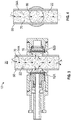
FIG. 1 depicts a cross-sectional view of an embodiment of a fire extinguishing agent concentration measuring system disclosed herein; -
FIG. 2 depicts an alternate cross-sectional view of the embodiment ofFigure 1 ; -
FIG. 3 depicts a cross-sectional view of a portion of another embodiment of a fire extinguishing agent concentration measuring system disclosed herein; -
FIG. 4 depicts an alternate cross-sectional view of the embodiment ofFigure 3 ; -
FIG. 5 depicts a cross-sectional view of a round shaped tube employed in an embodiment of an agent concentration measuring system disclosed herein; -
FIG. 6 depicts a cross-sectional view of an oval shaped tube employed in an alternate embodiment of an agent concentration measuring system disclosed herein; and -
FIG. 7 depicts a cross-sectional view of a polygonal shaped tube employed in yet another embodiment of an agent concentration measuring system disclosed herein. - A detailed description of one or more embodiments of the disclosed apparatus and method are presented herein by way of exemplification and not limitation with reference to the Figures.
-
Figures 1 and 2 depict a fire extinguishing agent concentration measuring system disclosed herein identified byreference character 10. Thesystem 10, in one embodiment includes, a housing 14 defining acavity 18, also referred to herein as a sensing volume, through which a fluid 20 (thefluid 20 containing a fire extinguishing agent 22) passes. Light is provided from alight source 26 through anoptical fiber 30. The light is transmitted from anend 34 of theoptical fiber 30 through a window orlens 38, then through thecavity 18, through anotherwindow 42 and impinges on amirror 46. Light reflected from themirror 46 travels in reverse back to asensor 50 located near thelight source 26. Thesensor 50 is calibrated to detect light received and correlate it to a concentration of theagent 22 present in thefluid 20 based on scatter of the light caused by the presence of theagent 22. While the embodiments illustrated in the figures herein include items such as, the housing 14, themirror 46, and theoptical fiber 30, alternate embodiments are contemplated that don't require these specific items. - A
tube 54 is fluidically connected to thecavity 18. At least oneend 58 of thetube 54 is in fluidic communication with anenvironment 62 that contains thefluid 20 with theagent 22. Afluid motion mechanism 66, such as a pump or a vacuum source, for example, is connected to thetube 54 to cause thefluid 20 to flow through thetube 54 and thus also through thecavity 18. - The
agent 22 may consist ofsolid particulates 70 that are emitted from acontainer 74 configured to hold theagent 22 until dispersion of theagent 22 is needed such as in the event of a fire, for example. Thecontainer 74 may be positioned within theenvironment 62 which may be housed within aturbine engine 78 or other system wherein quick extinguishment of a fire is desired. - Since an amount of light received by the
sensor 50 can in part be used to determine the concentration of theagent 22, anything that changes over time to increase obstruction of transmission of the light can cause error in the accuracy of the measurement being made. One such possible obstruction is the cleanliness ofsurfaces windows solid particulates 70 of theagent 22 becoming attached, such as by plating, to thesurfaces system 10 and methods disclosed herein are configured to reduce such plating. - The
fluid motion mechanism 66 and thetube 54 are specifically configured to draw thefluid 20 through thecavity 18 in a way such that plating of theagent 22 on thesurfaces fluid 20 through thetube 54 and through thecavity 18. - Referring to
Figures 3 and 4 , an alternate embodiment of a portion of an agent concentration measuring system disclosed herein is illustrated. A size oftube 54A is larger than that of thetube 54 in the embodiment ofFigures 1 and 2 . - Referring to
Figures 5, 6 and 7 , cross-sectional shapes oftubes Figure 5 , oval as shown inFigure 6 , or polygonal as shown by the rectangular shape inFigure 7 . - The
tube 54 includes anopening 86 that extends fully through thetube 54 that allows thefluid 20 flowing through thetube 54 to flow into and out of thecavity 18. Theopenings 86, thetube 54 and the cavity are configured to cause the fluid flow to be of a type (e.g., laminar or turbulent) that tends to decrease plating of the agent on thesurfaces - The
windows system 10 so that they can be easily cleaned. This allows thesystem 10 to be deployed during a test dump of thefluid 20 from thecontainer 74 to measure the concentration of theagent 22. After which, the windows can be cleaned in preparation of another test. - The term "about" is intended to include the degree of error associated with measurement of the particular quantity based upon the equipment available at the time of filing the application.
- The terminology used herein is for the purpose of describing particular embodiments only and is not intended to be limiting of the present disclosure. As used herein, the singular forms "a", "an" and "the" are intended to include the plural forms as well, unless the context clearly indicates otherwise. It will be further understood that the terms "comprises" and/or "comprising," when used in this specification, specify the presence of stated features, integers, steps, operations, elements, and/or components, but do not preclude the presence or addition of one or more other features, integers, steps, operations, element components, and/or groups thereof.
- While the present disclosure has been described with reference to an exemplary embodiment or embodiments, it will be understood by those skilled in the art that various changes may be made and equivalents may be substituted for elements thereof without departing from the scope of the present disclosure. In addition, many modifications may be made to adapt a particular situation or material to the teachings of the present disclosure without departing from the essential scope thereof. Therefore, it is intended that the present disclosure not be limited to the particular embodiment disclosed as the best mode contemplated for carrying out this present disclosure, but that the present disclosure will include all embodiments falling within the scope of the claims.
Claims (15)
- A fire extinguishing agent concentration measuring system comprising:a first window;a second window positioned relative to the first window thereby defining a sensing volume between the first window and the second window;a tube configured to port a flow including the agent from an environment through the sensing volume; anda fluid motion mechanism in operable communication with the tube configured to cause the flow through the tube and through the sensing volume.
- The fire extinguishing agent concentration system of claim 1, wherein the fluid motion mechanism is a pump.
- The fire extinguishing agent concentration system of claim 1, wherein the fluid motion mechanism is a vacuum source.
- The fire extinguishing agent concentration system of claim 1, 2 or 3, wherein flow through the tube is laminar.
- The fire extinguishing agent concentration system of claim 1, 2 or 3, wherein flow through the tube is turbulent.
- The fire extinguishing agent concentration system of any preceding claim, wherein the agent includes dry solid particulates.
- The fire extinguishing agent concentration system of any preceding claim, wherein a cross-sectional shape of the tube is one of circular, oval, and polygonal.
- The fire extinguishing agent concentration system of any preceding claim, wherein the tube includes openings to provide fluidic communication between the tube and the sensing volume.
- The fire extinguishing agent concentration system of any preceding claim, further comprising a sensor in operable communication with the sensing volume configured to determine a concentration of the agent based on an amount of light scattered by the agent as light travels through the sensing volume.
- A method of measuring a fire extinguishing agent within an environment, comprising:moving fluid containing the fire extinguishing agent from the environment through a tube;passing the fluid through a sensing volume defined in part by a first window and a second window;detecting light passing through the sensing volume; anddetermining a concentration of the fire extinguishing agent present in the fluid.
- The method of claim 10, wherein the moving fluid is via pumping.
- The method of claim 10, wherein moving the fluid is via drawing it with a vacuum source.
- The method of claim 10, 11 or 12, further comprising transmitting light through the first window, through the sensing volume and through the second window.
- The method of any one of claims 10-13, further comprising flowing the fluid through openings in the tube into the sensing volume.
- The method of any one of claims 10-14, further comprising flowing the fluid in laminar fashion through the sensing volume, or flowing the fluid in turbulent fashion through the sensing volume.
Applications Claiming Priority (1)
| Application Number | Priority Date | Filing Date | Title |
|---|---|---|---|
| US16/903,508 US11268891B2 (en) | 2020-06-17 | 2020-06-17 | Fire extinguishing agent concentration measuring system and method |
Publications (2)
| Publication Number | Publication Date |
|---|---|
| EP3926327A1 true EP3926327A1 (en) | 2021-12-22 |
| EP3926327B1 EP3926327B1 (en) | 2023-11-15 |
Family
ID=76844980
Family Applications (1)
| Application Number | Title | Priority Date | Filing Date |
|---|---|---|---|
| EP21179845.9A Active EP3926327B1 (en) | 2020-06-17 | 2021-06-16 | Fire extinguishing agent concentration measuring system and method |
Country Status (3)
| Country | Link |
|---|---|
| US (1) | US11268891B2 (en) |
| EP (1) | EP3926327B1 (en) |
| ES (1) | ES2965177T3 (en) |
Citations (3)
| Publication number | Priority date | Publication date | Assignee | Title |
|---|---|---|---|---|
| US3628028A (en) * | 1968-03-01 | 1971-12-14 | Honeywell Inc | Window cleaning apparatus for photometric instruments |
| US20140233017A1 (en) * | 2012-08-31 | 2014-08-21 | Sham S. Hariram | Measurement of Solid, Aerosol, Vapor, Liquid and Gaseous Concentration and Particle Size |
| US9207172B2 (en) * | 2011-05-26 | 2015-12-08 | Kidde Technologies, Inc. | Velocity survey with powderizer and agent flow indicator |
Family Cites Families (8)
| Publication number | Priority date | Publication date | Assignee | Title |
|---|---|---|---|---|
| US4434655A (en) | 1982-03-08 | 1984-03-06 | The United States Of America As Represented By The Secretary Of The Army | Black powder flamespread tester |
| US6833028B1 (en) * | 2001-02-09 | 2004-12-21 | The Scatter Works Inc. | Particle deposition system with enhanced speed and diameter accuracy |
| EP1441863B1 (en) | 2001-09-19 | 2006-12-27 | Kayyani C. Adiga | Fire suppression using water mist with ultrafine size droplets |
| EP1756547B1 (en) * | 2004-03-01 | 2014-05-14 | Partec GmbH | Device for measuring light emitted by microscopically small particles or biological cells |
| US8004684B2 (en) | 2009-04-09 | 2011-08-23 | Kidde Technologies, Inc. | Sensor head for a dry powder agent |
| KR102061714B1 (en) | 2009-07-07 | 2020-02-11 | 엑스트랄리스 테크놀로지 리미티드 | Chamber condition |
| WO2016063364A1 (en) * | 2014-10-22 | 2016-04-28 | 株式会社日立ハイテクノロジーズ | Cytometric mechanism, cell culture device comprising same, and cytometric method |
| US10267723B1 (en) * | 2018-01-23 | 2019-04-23 | Cbrn International, Ltd. | Bioaerosol particle detector |
-
2020
- 2020-06-17 US US16/903,508 patent/US11268891B2/en active Active
-
2021
- 2021-06-16 EP EP21179845.9A patent/EP3926327B1/en active Active
- 2021-06-16 ES ES21179845T patent/ES2965177T3/en active Active
Patent Citations (3)
| Publication number | Priority date | Publication date | Assignee | Title |
|---|---|---|---|---|
| US3628028A (en) * | 1968-03-01 | 1971-12-14 | Honeywell Inc | Window cleaning apparatus for photometric instruments |
| US9207172B2 (en) * | 2011-05-26 | 2015-12-08 | Kidde Technologies, Inc. | Velocity survey with powderizer and agent flow indicator |
| US20140233017A1 (en) * | 2012-08-31 | 2014-08-21 | Sham S. Hariram | Measurement of Solid, Aerosol, Vapor, Liquid and Gaseous Concentration and Particle Size |
Also Published As
| Publication number | Publication date |
|---|---|
| ES2965177T3 (en) | 2024-04-11 |
| EP3926327B1 (en) | 2023-11-15 |
| US20210396641A1 (en) | 2021-12-23 |
| US11268891B2 (en) | 2022-03-08 |
Similar Documents
| Publication | Publication Date | Title |
|---|---|---|
| AU2017201651B2 (en) | Fire detection | |
| EP1977215B1 (en) | Contaminant analyzer for fuel | |
| US8069738B2 (en) | Probe | |
| US11609144B2 (en) | Detection of leakage in an aspirating fire detection system | |
| US8992430B2 (en) | Breath sampling system | |
| CN111033219A (en) | Optical detection of black powder concentration in gas flow lines | |
| US8412481B2 (en) | Method and apparatus for determining operational condition of pollution monitoring equipment | |
| US11268891B2 (en) | Fire extinguishing agent concentration measuring system and method | |
| US20060215163A1 (en) | Air purged optical densitometer | |
| CN103298397B (en) | In-line flow meter | |
| US11442005B2 (en) | Gas analyser system | |
| EP4160185A1 (en) | Compressed gas cleaning of windows in particle concentration measurement device | |
| EP3929566B1 (en) | A fire extinguishing agent concentration measuring system and method of measuring a fire extinguishing agent within an environment | |
| WO2024112277A1 (en) | Particle detection device | |
| JP2016017925A (en) | Dust leakage monitoring system | |
| JP2019174174A (en) | Water quality analysis method | |
| EP3746766B1 (en) | Sensor system for detecting contaminant in fluid | |
| KR20120063238A (en) | Particle measuring apparatus | |
| JP2010025886A (en) | Soot concentration measuring device | |
| CZ188098A3 (en) | Apparatus for measuring concentration of air-borne fibers | |
| CN119688601B (en) | A methane and aerosol synchronous measurement chamber, system and working method | |
| US7256882B2 (en) | Photometer device and method | |
| HK1168415A1 (en) | Gas detector apparatus | |
| HK1168415B (en) | Gas detector apparatus | |
| AU2004274988A1 (en) | Method and apparatus for determining operational condition of pollution monitoring equipment |
Legal Events
| Date | Code | Title | Description |
|---|---|---|---|
| PUAI | Public reference made under article 153(3) epc to a published international application that has entered the european phase |
Free format text: ORIGINAL CODE: 0009012 |
|
| STAA | Information on the status of an ep patent application or granted ep patent |
Free format text: STATUS: THE APPLICATION HAS BEEN PUBLISHED |
|
| AK | Designated contracting states |
Kind code of ref document: A1 Designated state(s): AL AT BE BG CH CY CZ DE DK EE ES FI FR GB GR HR HU IE IS IT LI LT LU LV MC MK MT NL NO PL PT RO RS SE SI SK SM TR |
|
| B565 | Issuance of search results under rule 164(2) epc |
Effective date: 20211026 |
|
| STAA | Information on the status of an ep patent application or granted ep patent |
Free format text: STATUS: REQUEST FOR EXAMINATION WAS MADE |
|
| 17P | Request for examination filed |
Effective date: 20220622 |
|
| RBV | Designated contracting states (corrected) |
Designated state(s): AL AT BE BG CH CY CZ DE DK EE ES FI FR GB GR HR HU IE IS IT LI LT LU LV MC MK MT NL NO PL PT RO RS SE SI SK SM TR |
|
| GRAP | Despatch of communication of intention to grant a patent |
Free format text: ORIGINAL CODE: EPIDOSNIGR1 |
|
| STAA | Information on the status of an ep patent application or granted ep patent |
Free format text: STATUS: GRANT OF PATENT IS INTENDED |
|
| RIC1 | Information provided on ipc code assigned before grant |
Ipc: G01N 21/15 20060101ALN20230530BHEP Ipc: G01N 15/06 20060101ALI20230530BHEP Ipc: G01N 21/85 20060101ALI20230530BHEP Ipc: G01N 21/53 20060101AFI20230530BHEP |
|
| INTG | Intention to grant announced |
Effective date: 20230614 |
|
| GRAS | Grant fee paid |
Free format text: ORIGINAL CODE: EPIDOSNIGR3 |
|
| GRAA | (expected) grant |
Free format text: ORIGINAL CODE: 0009210 |
|
| STAA | Information on the status of an ep patent application or granted ep patent |
Free format text: STATUS: THE PATENT HAS BEEN GRANTED |
|
| AK | Designated contracting states |
Kind code of ref document: B1 Designated state(s): AL AT BE BG CH CY CZ DE DK EE ES FI FR GB GR HR HU IE IS IT LI LT LU LV MC MK MT NL NO PL PT RO RS SE SI SK SM TR |
|
| REG | Reference to a national code |
Ref country code: CH Ref legal event code: EP Ref country code: GB Ref legal event code: FG4D |
|
| REG | Reference to a national code |
Ref country code: DE Ref legal event code: R096 Ref document number: 602021006776 Country of ref document: DE |
|
| REG | Reference to a national code |
Ref country code: IE Ref legal event code: FG4D |
|
| REG | Reference to a national code |
Ref country code: LT Ref legal event code: MG9D |
|
| REG | Reference to a national code |
Ref country code: NL Ref legal event code: MP Effective date: 20231115 |
|
| PG25 | Lapsed in a contracting state [announced via postgrant information from national office to epo] |
Ref country code: GR Free format text: LAPSE BECAUSE OF FAILURE TO SUBMIT A TRANSLATION OF THE DESCRIPTION OR TO PAY THE FEE WITHIN THE PRESCRIBED TIME-LIMIT Effective date: 20240216 |
|
| PG25 | Lapsed in a contracting state [announced via postgrant information from national office to epo] |
Ref country code: IS Free format text: LAPSE BECAUSE OF FAILURE TO SUBMIT A TRANSLATION OF THE DESCRIPTION OR TO PAY THE FEE WITHIN THE PRESCRIBED TIME-LIMIT Effective date: 20240315 |
|
| REG | Reference to a national code |
Ref country code: ES Ref legal event code: FG2A Ref document number: 2965177 Country of ref document: ES Kind code of ref document: T3 Effective date: 20240411 |
|
| PG25 | Lapsed in a contracting state [announced via postgrant information from national office to epo] |
Ref country code: LT Free format text: LAPSE BECAUSE OF FAILURE TO SUBMIT A TRANSLATION OF THE DESCRIPTION OR TO PAY THE FEE WITHIN THE PRESCRIBED TIME-LIMIT Effective date: 20231115 |
|
| REG | Reference to a national code |
Ref country code: AT Ref legal event code: MK05 Ref document number: 1632200 Country of ref document: AT Kind code of ref document: T Effective date: 20231115 |
|
| PG25 | Lapsed in a contracting state [announced via postgrant information from national office to epo] |
Ref country code: NL Free format text: LAPSE BECAUSE OF FAILURE TO SUBMIT A TRANSLATION OF THE DESCRIPTION OR TO PAY THE FEE WITHIN THE PRESCRIBED TIME-LIMIT Effective date: 20231115 |
|
| PG25 | Lapsed in a contracting state [announced via postgrant information from national office to epo] |
Ref country code: AT Free format text: LAPSE BECAUSE OF FAILURE TO SUBMIT A TRANSLATION OF THE DESCRIPTION OR TO PAY THE FEE WITHIN THE PRESCRIBED TIME-LIMIT Effective date: 20231115 |
|
| PG25 | Lapsed in a contracting state [announced via postgrant information from national office to epo] |
Ref country code: NL Free format text: LAPSE BECAUSE OF FAILURE TO SUBMIT A TRANSLATION OF THE DESCRIPTION OR TO PAY THE FEE WITHIN THE PRESCRIBED TIME-LIMIT Effective date: 20231115 Ref country code: LT Free format text: LAPSE BECAUSE OF FAILURE TO SUBMIT A TRANSLATION OF THE DESCRIPTION OR TO PAY THE FEE WITHIN THE PRESCRIBED TIME-LIMIT Effective date: 20231115 Ref country code: IS Free format text: LAPSE BECAUSE OF FAILURE TO SUBMIT A TRANSLATION OF THE DESCRIPTION OR TO PAY THE FEE WITHIN THE PRESCRIBED TIME-LIMIT Effective date: 20240315 Ref country code: GR Free format text: LAPSE BECAUSE OF FAILURE TO SUBMIT A TRANSLATION OF THE DESCRIPTION OR TO PAY THE FEE WITHIN THE PRESCRIBED TIME-LIMIT Effective date: 20240216 Ref country code: BG Free format text: LAPSE BECAUSE OF FAILURE TO SUBMIT A TRANSLATION OF THE DESCRIPTION OR TO PAY THE FEE WITHIN THE PRESCRIBED TIME-LIMIT Effective date: 20240215 Ref country code: AT Free format text: LAPSE BECAUSE OF FAILURE TO SUBMIT A TRANSLATION OF THE DESCRIPTION OR TO PAY THE FEE WITHIN THE PRESCRIBED TIME-LIMIT Effective date: 20231115 Ref country code: PT Free format text: LAPSE BECAUSE OF FAILURE TO SUBMIT A TRANSLATION OF THE DESCRIPTION OR TO PAY THE FEE WITHIN THE PRESCRIBED TIME-LIMIT Effective date: 20240315 |
|
| PG25 | Lapsed in a contracting state [announced via postgrant information from national office to epo] |
Ref country code: SE Free format text: LAPSE BECAUSE OF FAILURE TO SUBMIT A TRANSLATION OF THE DESCRIPTION OR TO PAY THE FEE WITHIN THE PRESCRIBED TIME-LIMIT Effective date: 20231115 Ref country code: RS Free format text: LAPSE BECAUSE OF FAILURE TO SUBMIT A TRANSLATION OF THE DESCRIPTION OR TO PAY THE FEE WITHIN THE PRESCRIBED TIME-LIMIT Effective date: 20231115 Ref country code: PL Free format text: LAPSE BECAUSE OF FAILURE TO SUBMIT A TRANSLATION OF THE DESCRIPTION OR TO PAY THE FEE WITHIN THE PRESCRIBED TIME-LIMIT Effective date: 20231115 Ref country code: NO Free format text: LAPSE BECAUSE OF FAILURE TO SUBMIT A TRANSLATION OF THE DESCRIPTION OR TO PAY THE FEE WITHIN THE PRESCRIBED TIME-LIMIT Effective date: 20240215 Ref country code: LV Free format text: LAPSE BECAUSE OF FAILURE TO SUBMIT A TRANSLATION OF THE DESCRIPTION OR TO PAY THE FEE WITHIN THE PRESCRIBED TIME-LIMIT Effective date: 20231115 Ref country code: HR Free format text: LAPSE BECAUSE OF FAILURE TO SUBMIT A TRANSLATION OF THE DESCRIPTION OR TO PAY THE FEE WITHIN THE PRESCRIBED TIME-LIMIT Effective date: 20231115 |
|
| PG25 | Lapsed in a contracting state [announced via postgrant information from national office to epo] |
Ref country code: DK Free format text: LAPSE BECAUSE OF FAILURE TO SUBMIT A TRANSLATION OF THE DESCRIPTION OR TO PAY THE FEE WITHIN THE PRESCRIBED TIME-LIMIT Effective date: 20231115 |
|
| PG25 | Lapsed in a contracting state [announced via postgrant information from national office to epo] |
Ref country code: CZ Free format text: LAPSE BECAUSE OF FAILURE TO SUBMIT A TRANSLATION OF THE DESCRIPTION OR TO PAY THE FEE WITHIN THE PRESCRIBED TIME-LIMIT Effective date: 20231115 |
|
| PG25 | Lapsed in a contracting state [announced via postgrant information from national office to epo] |
Ref country code: SK Free format text: LAPSE BECAUSE OF FAILURE TO SUBMIT A TRANSLATION OF THE DESCRIPTION OR TO PAY THE FEE WITHIN THE PRESCRIBED TIME-LIMIT Effective date: 20231115 |
|
| PG25 | Lapsed in a contracting state [announced via postgrant information from national office to epo] |
Ref country code: SM Free format text: LAPSE BECAUSE OF FAILURE TO SUBMIT A TRANSLATION OF THE DESCRIPTION OR TO PAY THE FEE WITHIN THE PRESCRIBED TIME-LIMIT Effective date: 20231115 Ref country code: SK Free format text: LAPSE BECAUSE OF FAILURE TO SUBMIT A TRANSLATION OF THE DESCRIPTION OR TO PAY THE FEE WITHIN THE PRESCRIBED TIME-LIMIT Effective date: 20231115 Ref country code: RO Free format text: LAPSE BECAUSE OF FAILURE TO SUBMIT A TRANSLATION OF THE DESCRIPTION OR TO PAY THE FEE WITHIN THE PRESCRIBED TIME-LIMIT Effective date: 20231115 Ref country code: EE Free format text: LAPSE BECAUSE OF FAILURE TO SUBMIT A TRANSLATION OF THE DESCRIPTION OR TO PAY THE FEE WITHIN THE PRESCRIBED TIME-LIMIT Effective date: 20231115 Ref country code: DK Free format text: LAPSE BECAUSE OF FAILURE TO SUBMIT A TRANSLATION OF THE DESCRIPTION OR TO PAY THE FEE WITHIN THE PRESCRIBED TIME-LIMIT Effective date: 20231115 Ref country code: CZ Free format text: LAPSE BECAUSE OF FAILURE TO SUBMIT A TRANSLATION OF THE DESCRIPTION OR TO PAY THE FEE WITHIN THE PRESCRIBED TIME-LIMIT Effective date: 20231115 |
|
| REG | Reference to a national code |
Ref country code: DE Ref legal event code: R097 Ref document number: 602021006776 Country of ref document: DE |
|
| PLBE | No opposition filed within time limit |
Free format text: ORIGINAL CODE: 0009261 |
|
| STAA | Information on the status of an ep patent application or granted ep patent |
Free format text: STATUS: NO OPPOSITION FILED WITHIN TIME LIMIT |
|
| 26N | No opposition filed |
Effective date: 20240819 |
|
| PG25 | Lapsed in a contracting state [announced via postgrant information from national office to epo] |
Ref country code: SI Free format text: LAPSE BECAUSE OF FAILURE TO SUBMIT A TRANSLATION OF THE DESCRIPTION OR TO PAY THE FEE WITHIN THE PRESCRIBED TIME-LIMIT Effective date: 20231115 |
|
| PG25 | Lapsed in a contracting state [announced via postgrant information from national office to epo] |
Ref country code: SI Free format text: LAPSE BECAUSE OF FAILURE TO SUBMIT A TRANSLATION OF THE DESCRIPTION OR TO PAY THE FEE WITHIN THE PRESCRIBED TIME-LIMIT Effective date: 20231115 |
|
| PG25 | Lapsed in a contracting state [announced via postgrant information from national office to epo] |
Ref country code: MC Free format text: LAPSE BECAUSE OF FAILURE TO SUBMIT A TRANSLATION OF THE DESCRIPTION OR TO PAY THE FEE WITHIN THE PRESCRIBED TIME-LIMIT Effective date: 20231115 |
|
| REG | Reference to a national code |
Ref country code: CH Ref legal event code: PL |
|
| PG25 | Lapsed in a contracting state [announced via postgrant information from national office to epo] |
Ref country code: LU Free format text: LAPSE BECAUSE OF NON-PAYMENT OF DUE FEES Effective date: 20240616 |
|
| PG25 | Lapsed in a contracting state [announced via postgrant information from national office to epo] |
Ref country code: IE Free format text: LAPSE BECAUSE OF NON-PAYMENT OF DUE FEES Effective date: 20240616 |
|
| PG25 | Lapsed in a contracting state [announced via postgrant information from national office to epo] |
Ref country code: BE Free format text: LAPSE BECAUSE OF NON-PAYMENT OF DUE FEES Effective date: 20240630 Ref country code: CH Free format text: LAPSE BECAUSE OF NON-PAYMENT OF DUE FEES Effective date: 20240630 |
|
| REG | Reference to a national code |
Ref country code: BE Ref legal event code: MM Effective date: 20240630 |
|
| PGFP | Annual fee paid to national office [announced via postgrant information from national office to epo] |
Ref country code: DE Payment date: 20250520 Year of fee payment: 5 |
|
| PGFP | Annual fee paid to national office [announced via postgrant information from national office to epo] |
Ref country code: GB Payment date: 20250520 Year of fee payment: 5 |
|
| PGFP | Annual fee paid to national office [announced via postgrant information from national office to epo] |
Ref country code: IT Payment date: 20250520 Year of fee payment: 5 |
|
| PGFP | Annual fee paid to national office [announced via postgrant information from national office to epo] |
Ref country code: FR Payment date: 20250521 Year of fee payment: 5 |
|
| PG25 | Lapsed in a contracting state [announced via postgrant information from national office to epo] |
Ref country code: FI Free format text: LAPSE BECAUSE OF FAILURE TO SUBMIT A TRANSLATION OF THE DESCRIPTION OR TO PAY THE FEE WITHIN THE PRESCRIBED TIME-LIMIT Effective date: 20231115 |
|
| PGFP | Annual fee paid to national office [announced via postgrant information from national office to epo] |
Ref country code: ES Payment date: 20250701 Year of fee payment: 5 |
|
| PG25 | Lapsed in a contracting state [announced via postgrant information from national office to epo] |
Ref country code: CY Free format text: LAPSE BECAUSE OF FAILURE TO SUBMIT A TRANSLATION OF THE DESCRIPTION OR TO PAY THE FEE WITHIN THE PRESCRIBED TIME-LIMIT; INVALID AB INITIO Effective date: 20210616 |
|
| P01 | Opt-out of the competence of the unified patent court (upc) registered |
Free format text: CASE NUMBER: UPC_APP_0000114_3926327/2026 Effective date: 20260105 |
|
| PG25 | Lapsed in a contracting state [announced via postgrant information from national office to epo] |
Ref country code: HU Free format text: LAPSE BECAUSE OF FAILURE TO SUBMIT A TRANSLATION OF THE DESCRIPTION OR TO PAY THE FEE WITHIN THE PRESCRIBED TIME-LIMIT; INVALID AB INITIO Effective date: 20210616 |