EP3926324A1 - Particle sorter, particle sorting method, and micro flow path cartridge - Google Patents
Particle sorter, particle sorting method, and micro flow path cartridge Download PDFInfo
- Publication number
- EP3926324A1 EP3926324A1 EP21180003.2A EP21180003A EP3926324A1 EP 3926324 A1 EP3926324 A1 EP 3926324A1 EP 21180003 A EP21180003 A EP 21180003A EP 3926324 A1 EP3926324 A1 EP 3926324A1
- Authority
- EP
- European Patent Office
- Prior art keywords
- flow path
- sorting
- sample
- particle
- target
- Prior art date
- Legal status (The legal status is an assumption and is not a legal conclusion. Google has not performed a legal analysis and makes no representation as to the accuracy of the status listed.)
- Withdrawn
Links
Images







Classifications
-
- G—PHYSICS
- G01—MEASURING; TESTING
- G01N—INVESTIGATING OR ANALYSING MATERIALS BY DETERMINING THEIR CHEMICAL OR PHYSICAL PROPERTIES
- G01N15/00—Investigating characteristics of particles; Investigating permeability, pore-volume or surface-area of porous materials
- G01N15/10—Investigating individual particles
-
- G—PHYSICS
- G01—MEASURING; TESTING
- G01N—INVESTIGATING OR ANALYSING MATERIALS BY DETERMINING THEIR CHEMICAL OR PHYSICAL PROPERTIES
- G01N15/00—Investigating characteristics of particles; Investigating permeability, pore-volume or surface-area of porous materials
- G01N15/10—Investigating individual particles
- G01N15/14—Optical investigation techniques, e.g. flow cytometry
- G01N15/1456—Optical investigation techniques, e.g. flow cytometry without spatial resolution of the texture or inner structure of the particle, e.g. processing of pulse signals
- G01N15/1459—Optical investigation techniques, e.g. flow cytometry without spatial resolution of the texture or inner structure of the particle, e.g. processing of pulse signals the analysis being performed on a sample stream
-
- B—PERFORMING OPERATIONS; TRANSPORTING
- B01—PHYSICAL OR CHEMICAL PROCESSES OR APPARATUS IN GENERAL
- B01L—CHEMICAL OR PHYSICAL LABORATORY APPARATUS FOR GENERAL USE
- B01L3/00—Containers or dishes for laboratory use, e.g. laboratory glassware; Droppers
- B01L3/50—Containers for the purpose of retaining a material to be analysed, e.g. test tubes
- B01L3/502—Containers for the purpose of retaining a material to be analysed, e.g. test tubes with fluid transport, e.g. in multi-compartment structures
- B01L3/5027—Containers for the purpose of retaining a material to be analysed, e.g. test tubes with fluid transport, e.g. in multi-compartment structures by integrated microfluidic structures, i.e. dimensions of channels and chambers are such that surface tension forces are important, e.g. lab-on-a-chip
- B01L3/502738—Containers for the purpose of retaining a material to be analysed, e.g. test tubes with fluid transport, e.g. in multi-compartment structures by integrated microfluidic structures, i.e. dimensions of channels and chambers are such that surface tension forces are important, e.g. lab-on-a-chip characterised by integrated valves
-
- B—PERFORMING OPERATIONS; TRANSPORTING
- B01—PHYSICAL OR CHEMICAL PROCESSES OR APPARATUS IN GENERAL
- B01L—CHEMICAL OR PHYSICAL LABORATORY APPARATUS FOR GENERAL USE
- B01L3/00—Containers or dishes for laboratory use, e.g. laboratory glassware; Droppers
- B01L3/50—Containers for the purpose of retaining a material to be analysed, e.g. test tubes
- B01L3/502—Containers for the purpose of retaining a material to be analysed, e.g. test tubes with fluid transport, e.g. in multi-compartment structures
- B01L3/5027—Containers for the purpose of retaining a material to be analysed, e.g. test tubes with fluid transport, e.g. in multi-compartment structures by integrated microfluidic structures, i.e. dimensions of channels and chambers are such that surface tension forces are important, e.g. lab-on-a-chip
- B01L3/502761—Containers for the purpose of retaining a material to be analysed, e.g. test tubes with fluid transport, e.g. in multi-compartment structures by integrated microfluidic structures, i.e. dimensions of channels and chambers are such that surface tension forces are important, e.g. lab-on-a-chip specially adapted for handling suspended solids or molecules independently from the bulk fluid flow, e.g. for trapping or sorting beads or physically stretching molecules
-
- B—PERFORMING OPERATIONS; TRANSPORTING
- B01—PHYSICAL OR CHEMICAL PROCESSES OR APPARATUS IN GENERAL
- B01L—CHEMICAL OR PHYSICAL LABORATORY APPARATUS FOR GENERAL USE
- B01L3/00—Containers or dishes for laboratory use, e.g. laboratory glassware; Droppers
- B01L3/56—Labware specially adapted for transferring fluids
- B01L3/567—Valves, taps or stop-cocks
-
- B—PERFORMING OPERATIONS; TRANSPORTING
- B07—SEPARATING SOLIDS FROM SOLIDS; SORTING
- B07C—POSTAL SORTING; SORTING INDIVIDUAL ARTICLES, OR BULK MATERIAL FIT TO BE SORTED PIECE-MEAL, e.g. BY PICKING
- B07C5/00—Sorting according to a characteristic or feature of the articles or material being sorted, e.g. by control effected by devices which detect or measure such characteristic or feature; Sorting by manually actuated devices, e.g. switches
- B07C5/36—Sorting apparatus characterised by the means used for distribution
- B07C5/361—Processing or control devices therefor, e.g. escort memory
- B07C5/362—Separating or distributor mechanisms
-
- C—CHEMISTRY; METALLURGY
- C12—BIOCHEMISTRY; BEER; SPIRITS; WINE; VINEGAR; MICROBIOLOGY; ENZYMOLOGY; MUTATION OR GENETIC ENGINEERING
- C12Q—MEASURING OR TESTING PROCESSES INVOLVING ENZYMES, NUCLEIC ACIDS OR MICROORGANISMS; COMPOSITIONS OR TEST PAPERS THEREFOR; PROCESSES OF PREPARING SUCH COMPOSITIONS; CONDITION-RESPONSIVE CONTROL IN MICROBIOLOGICAL OR ENZYMOLOGICAL PROCESSES
- C12Q1/00—Measuring or testing processes involving enzymes, nucleic acids or microorganisms; Compositions therefor; Processes of preparing such compositions
- C12Q1/02—Measuring or testing processes involving enzymes, nucleic acids or microorganisms; Compositions therefor; Processes of preparing such compositions involving viable microorganisms
-
- G—PHYSICS
- G01—MEASURING; TESTING
- G01N—INVESTIGATING OR ANALYSING MATERIALS BY DETERMINING THEIR CHEMICAL OR PHYSICAL PROPERTIES
- G01N1/00—Sampling; Preparing specimens for investigation
- G01N1/28—Preparing specimens for investigation including physical details of (bio-)chemical methods covered elsewhere, e.g. G01N33/50, C12Q
- G01N1/40—Concentrating samples
- G01N1/4077—Concentrating samples by other techniques involving separation of suspended solids
-
- G—PHYSICS
- G01—MEASURING; TESTING
- G01N—INVESTIGATING OR ANALYSING MATERIALS BY DETERMINING THEIR CHEMICAL OR PHYSICAL PROPERTIES
- G01N15/00—Investigating characteristics of particles; Investigating permeability, pore-volume or surface-area of porous materials
- G01N15/10—Investigating individual particles
- G01N15/1023—Microstructural devices for non-optical measurement
-
- G—PHYSICS
- G01—MEASURING; TESTING
- G01N—INVESTIGATING OR ANALYSING MATERIALS BY DETERMINING THEIR CHEMICAL OR PHYSICAL PROPERTIES
- G01N15/00—Investigating characteristics of particles; Investigating permeability, pore-volume or surface-area of porous materials
- G01N15/10—Investigating individual particles
- G01N15/14—Optical investigation techniques, e.g. flow cytometry
- G01N15/1484—Optical investigation techniques, e.g. flow cytometry microstructural devices
-
- G—PHYSICS
- G01—MEASURING; TESTING
- G01N—INVESTIGATING OR ANALYSING MATERIALS BY DETERMINING THEIR CHEMICAL OR PHYSICAL PROPERTIES
- G01N35/00—Automatic analysis not limited to methods or materials provided for in any single one of groups G01N1/00 - G01N33/00; Handling materials therefor
- G01N35/10—Devices for transferring samples or any liquids to, in, or from, the analysis apparatus, e.g. suction devices, injection devices
- G01N35/1009—Characterised by arrangements for controlling the aspiration or dispense of liquids
-
- B—PERFORMING OPERATIONS; TRANSPORTING
- B01—PHYSICAL OR CHEMICAL PROCESSES OR APPARATUS IN GENERAL
- B01L—CHEMICAL OR PHYSICAL LABORATORY APPARATUS FOR GENERAL USE
- B01L2200/00—Solutions for specific problems relating to chemical or physical laboratory apparatus
- B01L2200/06—Fluid handling related problems
- B01L2200/0647—Handling flowable solids, e.g. microscopic beads, cells, particles
- B01L2200/0652—Sorting or classification of particles or molecules
-
- B—PERFORMING OPERATIONS; TRANSPORTING
- B01—PHYSICAL OR CHEMICAL PROCESSES OR APPARATUS IN GENERAL
- B01L—CHEMICAL OR PHYSICAL LABORATORY APPARATUS FOR GENERAL USE
- B01L2200/00—Solutions for specific problems relating to chemical or physical laboratory apparatus
- B01L2200/14—Process control and prevention of errors
- B01L2200/143—Quality control, feedback systems
-
- B—PERFORMING OPERATIONS; TRANSPORTING
- B01—PHYSICAL OR CHEMICAL PROCESSES OR APPARATUS IN GENERAL
- B01L—CHEMICAL OR PHYSICAL LABORATORY APPARATUS FOR GENERAL USE
- B01L2300/00—Additional constructional details
- B01L2300/08—Geometry, shape and general structure
- B01L2300/0809—Geometry, shape and general structure rectangular shaped
- B01L2300/0816—Cards, e.g. flat sample carriers usually with flow in two horizontal directions
-
- B—PERFORMING OPERATIONS; TRANSPORTING
- B01—PHYSICAL OR CHEMICAL PROCESSES OR APPARATUS IN GENERAL
- B01L—CHEMICAL OR PHYSICAL LABORATORY APPARATUS FOR GENERAL USE
- B01L2300/00—Additional constructional details
- B01L2300/12—Specific details about materials
- B01L2300/123—Flexible; Elastomeric
-
- B—PERFORMING OPERATIONS; TRANSPORTING
- B01—PHYSICAL OR CHEMICAL PROCESSES OR APPARATUS IN GENERAL
- B01L—CHEMICAL OR PHYSICAL LABORATORY APPARATUS FOR GENERAL USE
- B01L2400/00—Moving or stopping fluids
- B01L2400/04—Moving fluids with specific forces or mechanical means
- B01L2400/0403—Moving fluids with specific forces or mechanical means specific forces
- B01L2400/0415—Moving fluids with specific forces or mechanical means specific forces electrical forces, e.g. electrokinetic
-
- B—PERFORMING OPERATIONS; TRANSPORTING
- B01—PHYSICAL OR CHEMICAL PROCESSES OR APPARATUS IN GENERAL
- B01L—CHEMICAL OR PHYSICAL LABORATORY APPARATUS FOR GENERAL USE
- B01L2400/00—Moving or stopping fluids
- B01L2400/06—Valves, specific forms thereof
- B01L2400/0633—Valves, specific forms thereof with moving parts
- B01L2400/0655—Valves, specific forms thereof with moving parts pinch valves
-
- G—PHYSICS
- G01—MEASURING; TESTING
- G01N—INVESTIGATING OR ANALYSING MATERIALS BY DETERMINING THEIR CHEMICAL OR PHYSICAL PROPERTIES
- G01N15/00—Investigating characteristics of particles; Investigating permeability, pore-volume or surface-area of porous materials
- G01N15/10—Investigating individual particles
- G01N15/14—Optical investigation techniques, e.g. flow cytometry
- G01N15/149—Optical investigation techniques, e.g. flow cytometry specially adapted for sorting particles, e.g. by their size or optical properties
-
- G—PHYSICS
- G01—MEASURING; TESTING
- G01N—INVESTIGATING OR ANALYSING MATERIALS BY DETERMINING THEIR CHEMICAL OR PHYSICAL PROPERTIES
- G01N15/00—Investigating characteristics of particles; Investigating permeability, pore-volume or surface-area of porous materials
- G01N15/10—Investigating individual particles
- G01N2015/1006—Investigating individual particles for cytology
-
- G—PHYSICS
- G01—MEASURING; TESTING
- G01N—INVESTIGATING OR ANALYSING MATERIALS BY DETERMINING THEIR CHEMICAL OR PHYSICAL PROPERTIES
- G01N15/00—Investigating characteristics of particles; Investigating permeability, pore-volume or surface-area of porous materials
- G01N15/10—Investigating individual particles
- G01N2015/1028—Sorting particles
Definitions
- the present invention relates to a particle sorter for separating target particles from a sample, a particle separation method, and a micro flow path cartridge.
- FIG. 36 discloses a replaceable flow path cartridge 900 including a sample reservoir 901, a waste liquid reservoir 902, a sheath liquid reservoir 903, a sorting liquid reservoir 904, a recovery reservoir 905, a main flow path 906, a sheath flow path 907, and a sorting flow path 908.
- a sample flows from the sample reservoir 901 to the main flow path 906.
- the sheath liquid joins the main flow path 906 from the sheath liquid reservoir 903 through the sheath flow path 907. Specific particles flowing through the main flow path 906 are detected in the detection region 909.
- a sorting pulse flow from the sorting liquid reservoir 904 to the recovery reservoir 905 is generated by pulsed air pressure with a timing such that the particles determined to be the sorting target particles pass through the intersection of the main flow path 906 and the sorting flow path 908 so as to separate the target particles.
- the present invention provides a particle sorter, a particle sorting method, and a micro flow path cartridge that can reduce the time required to sort target particles with sufficient purity.
- a particle sorter is a particle sorter (200) including a micro flow path cartridge (100) including a first flow path (10) comprising a detection region (11) for detecting target particles contained in a sample and a sorting region (12) for obtaining a target particle-containing sample (81) containing the detected target particles, and a second flow path (20) for returning the target particle-containing sample to upstream of the detection region; an installation part (110) where the micro flow path cartridge is installed; a liquid feeder (120) configured to feed liquid in the micro flow path cartridge; a detector (130) configured to output a signal corresponding to the target particle passing through the detection region; a sorting mechanism (140) configured to perform a sorting operation for obtaining the target particle-containing sample in the sorting region based on the signal from the detector; and a controller (150) configured to control the liquid feeder such that the target particle-containing sample obtained in the sorting region is returned to upstream of the detection region via the second flow path, and control the sort
- the sorting operation can be repeated a plurality of times inside the micro flow path cartridge (100) by returning the sample using the second flow path (20) formed in the micro flow path cartridge (100).
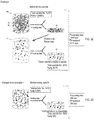
- the target particle-containing sample (81) obtained by the sorting operation also includes particles other than the target particles (91) flowing near the target particles (91) in the sorting region (12). Therefore, the target particles (91) can be sorted with high purity even if the sample flows at a higher speed than in the case where the sorting process is performed only once by performing the sorting operation a plurality of times. As a result, the time required to sort the target particles (91) with sufficient purity can be shortened in the overall sorting process.
- a particle sorting method is a method for sorting target particles (91) using a micro flow path cartridge (100) including a first flow path (10) comprising a detection region (11) for detecting target particles contained in a sample and a sorting region (12) for obtaining a target particle-containing sample (81) containing the detected target particles, and a second flow path (20) for returning the target particle-containing sample to upstream of the detection region, the particle sorting method comprising: obtaining (S1) the target particle-containing sample from the sample by feeding the sample to the first flow path of the micro flow path cartridge and performing a sorting operation in the sorting region based on a signal corresponding to the target particle passing through the detection region; returning (S2) the target particle-containing sample obtained by the obtaining to the first flow path via the second flow path; and feeding (S3) the returned target particle-containing sample to the detection region and the sorting region of the first flow path and performing the sorting operation based on the signal corresponding to the target particle passing through
- the first sorting step (S1) and the second sorting step (S3) can be performed a plurality of times by performing the above-mentioned return step (S2).
- the target particles (91) can be sorted with high purity even if the sample flows at a higher speed than compared to when the sorting process is performed only once, by performing the sorting operation a plurality of times. Therefore, the time required to sort the target particles (91) with sufficient purity can be shortened similar to the first invention.
- a micro flow path cartridge (100) according to a third invention, shown in FIG. 1 is the micro flow path cartridge (100) including a flow path forming body (40) in which a flow path (MC) for flowing a sample (91) containing target particles is formed; wherein the flow path comprises a first flow path (10) having a detection region (11) for detecting the target particles contained in the sample and a sorting region (12) for obtaining the detected target particles (81), and a second flow path (20) for returning the target particle-containing sample containing the target particles upstream of the detection region of the first flow path.
- MC flow path forming body
- the flow path comprises a first flow path (10) having a detection region (11) for detecting the target particles contained in the sample and a sorting region (12) for obtaining the detected target particles (81), and a second flow path (20) for returning the target particle-containing sample containing the target particles upstream of the detection region of the first flow path.
- the micro flow path cartridge (100) has, as described above, a flow path (MC) which includes a second flow path (20) for returning the target particle-containing sample (81) containing the sorted target particles (91) to upstream of the detection region (11) of the first flow path (10).
- the sorting operation can be repeated a plurality of times using the second flow path (20) similar to the first invention. Therefore, the target particles (91) can be sorted with high purity even if the sample flows at a higher speed compared to when the sorting process is performed only once, by performing the sorting operation a plurality of times. As a result, the time required to sort the target particles (91) with sufficient purity can be shortened.
- the particle sorter 200 is a device that uses the micro flow path cartridge 100 to perform a process of sorting target particles 91 in a sample 80 flowing in the flow path MC of the micro flow path cartridge 100.
- Sorting means separating the target substance from the sample solution.
- Sample 80 is a liquid containing a large number of particles.
- the sample 80 includes a target particle 91 and a non-target particle 92 in addition to the target particle 91.
- Particles are a general term for small objects, regardless of their constituent materials or structures. As used herein, particles are a broad concept that includes particulate matter of cells, macromolecules, inorganic or organic materials.
- the target particle 91 may be (1) cells, (2) granules such as exosomes, or (3) droplets containing a predetermined component.
- cells include rare cells (circulating tumor cells (CTC), circulating rare cells (CRC), endothelial cancer cells and the like, primary B cells, antibody-producing hybridoma, germ cells (sperm, egg, embryo), and each single cell in cell-cell interaction and the like.
- Predetermined components contained in droplets include, for example, drug molecules, viruses, nucleic acids (DNA, RNA and the like), proteins (antibodies, biomarkers, enzymes) and the like.
- the particle sorter 200 performs a process of separating and recovering the target particle-containing sample 81 containing the target particles 91 from the sample 80 flowing through the flow path MC.
- sorting does not mean that the collected sample contains only the target particles 91.
- the sorting process by the particle sorter 200 is to increase the ratio (purity) of the number of target particles to the total number of particles in the sample.
- the purity of the target particles 91 in the target particle-containing sample 81 is higher than the purity of the target particles 91 in the sample 80 before sorting. Therefore, the recovered target particle-containing sample 81 contains most of the target particles 91 and some non-target particles 92 among the sample 80 that was first introduced into the micro flow path cartridge 100.
- the number of target particles 91 in the recovered target particle-containing sample 81 is not necessarily larger than the number of non-target particles 92.
- the number of target particles 91 in the recovered sample may be less than the number of non-target particles 92 mixed in the recovered sample together with the target particles 91.
- the particle sorter 200 includes an installation unit 110, a liquid feeding unit 120, a detection unit 130, a sorting mechanism 140, and a control unit 150.
- the installation unit 110 provides an installation location for the micro flow path cartridge 100.
- the installation unit 110 contacts a part of the micro flow path cartridge 100 and holds the micro flow path cartridge 100.
- the installation unit 110 supports, for example, the lower surface of the micro flow path cartridge 100.
- the micro flow path cartridge 100 installed in the installation unit 110 is configured with a first flow path 10 having a detection region 11 for detecting the target particles 91 contained in the sample and a branched sorting region 12 for sorting a target particle-containing sample 81 containing the detected target particles 91, and a second flow path 20 for returning the target particle-containing sample 81 upstream of the detection region 11 of the first flow path 10.
- the detection region 11 and the sorting region 12 are arranged in order from the upstream side.
- the liquid feeding unit 120 is configured to feed a liquid in the micro flow path cartridge 100.
- the liquid feeding unit 120 can feed the sample 80 in the micro flow path cartridge 100 from the upstream to the downstream of the first flow path 10.
- the liquid feeding unit 120 can feed the target particle-containing sample 81 that has passed through the sorting region 12 from the upstream to the downstream of the second flow path 20.
- the target particle-containing sample 81 is returned to the first flow path 10 by the liquid transfer through the second flow path 20.
- the liquid feeding unit 120 can feed the target particle-containing sample 81 returned to the first flow path 10 from the upstream to the downstream of the first flow path 10.
- the liquid feeding unit 120 feeds the liquid in the micro flow path cartridge 100 by pressure, for example.
- the liquid feeding unit 120 pressurizes and feeds the liquid, for example, by applying a positive pressure to the upstream side of the flow path MC.
- the liquid feeding unit 120 also may send the liquid in a form of suctioning the liquid by applying a negative pressure to the downstream side of the flow path MC, for example.
- the liquid feeding unit 120 includes, for example, a pump and a valve.
- the detection unit 130 is configured to output a signal corresponding to the target particle 91 passing through the detection region 11. That is, the target particles 91 in the sample 80 flowing from the upstream to the downstream of the first flow path 10 by the liquid feeding unit 120 are detected by the detection unit 130 when passing through the detection region 11.
- the detection unit 130 outputs a signal reflecting the presence of the target particle 91 to the control unit 150.
- the method for detecting the target particles 91 by the detection unit 130 is not particularly limited.
- the target particle 91 may be labeled for detection.
- the target particle 91 can be labeled with a labeled antibody that specifically binds to the target particle 91.
- a method according to the detection method is selected from the known labeling methods.
- a method such as fluorescence detection, magnetic detection, image detection, or electric detection may be adopted.
- fluorescence detection the detection unit 130 detects the target particles 91 by detecting the fluorescence generated from the fluorescent label with a photodetector.
- magnetic detection the detection unit 130 detects the target particles 91 labeled with the magnetic particles by the magnetic detector.
- the detection unit 130 photographs the target particles 91 passing through the detection region 11 with an image sensor, and detects the target particles 91 by image recognition.
- the detection unit 130 detects the target particles 91 based on the change in electrical resistance and the change in impedance due to the passage of the target particles 91 between electrodes provided in the detection region 11.
- the sorting mechanism 140 is configured to perform a sorting operation for sorting the target particle-containing sample 81 in the sorting region 12 based on the signal from the detection unit 130.
- the first flow path 10 is branched.
- the number of branches is at least two .
- the sorting region 12 is bifurcated into a first guide path 12a and a second guide path 12b.
- the sorting mechanism 140 causes the target particles 91 detected by the detection unit 130 in the detection region 11 to flow into one specific flow path (first guide path 12a) in the sorting region 12.
- first guide path 12a specific flow path
- the sorting mechanism 140 causes the non-target particles 92 to flow into a flow path (second guide path 12b) that is different from that of the target particles 91. In this way the target particle-containing sample 81 is sorted in the sorting region 12.
- the method of sorting the target particles 91 by the sorting mechanism 140 is not particularly limited.
- the sorting mechanism 140 may apply some external force to the target particle 91 itself or a small volume sample 80 containing the target particle 91 in the first flow path 10 for sorting.
- a laser method, a pressure method, an electric method, a magnetic method, an acoustic wave method, a flow path switching method, or the like may be employed.
- the sorting mechanism 140 irradiates the sample 80 flowing through the sorting region 12 with laser light to generate minute bubbles to cause a pressure change, thereby pushing the target particles 91 into the first guide path 12a.
- the sorting mechanism 140 sends the target particles 91 to the first guide path 12a by applying pressure in a direction crossing the sorting region 12. The pressure is applied from the outside of the micro flow path cartridge 100 or via an actuator provided inside the micro flow path cartridge 100.
- the sorting mechanism 140 charges the target particles 91 and sends the target particles 91 to the first guide path 12a by the principle of dielectrophoresis.
- the sorting mechanism 140 sends the target particles 91 to the first guide path 12a by applying a magnetic force to the target particles 91 bonded to the magnetic particles.
- the sorting mechanism unit 140 sends the target particles 91 to the first guide path 12a by applying an acoustic wave to the sorting region 12 by a transducer and forming a pressure gradient in the flow path MC.
- the particles 91 are sent to the first guide path 12a and the non-target particles 92 are sent to the second guide path 12b by the sorting mechanism 140 driving a valve structure provided in the micro flow path cartridge 100 to open and close the first guide path 12a and the second guide path 12b from the outside.
- the control unit 150 is configured to control the liquid feeding unit 120, the detection unit 130, and the sorting mechanism 140.
- the control unit 150 controls the liquid feeding unit 120 to start, stop, open/close the valve, and the like.
- the control unit 150 controls the detection unit 130 and acquires a signal from the detection unit 130.
- the control unit 150 controls the sorting operation by the sorting mechanism 140 based on the signal corresponding to the target particle 91.
- the control unit 150 is configured by a computer and includes one or more processors and a storage unit including volatile memory and non-volatile memory.
- the target particle-containing sample 81 includes sorted target particles 91, and non-target particles 92 mixed with the target particles 91.
- the control unit 150 controls the liquid feeding unit 120 to return the target particle-containing sample 81 sorted by the sorting mechanism 140 to upstream of the detection region 11 of the first flow path 10 via the second flow path 20, and controls the sorting mechanism 140 to perform a sorting operation on the returned target particle-containing sample 81. That is, in the present embodiment, the first sorting operation is performed on the sample 80, and the second sorting operation is performed on the target particle-containing sample 81 collected as a result of the first sorting operation. The sorting operation also may be performed three or more times. The proportion of the non-target particles 92 decreases, and the purity of the target particles 91 increases by repeating the sorting operation.
- the control unit 150 controls the liquid feeding unit 120 to return the target particle-containing sample 81 sorted by the sorting mechanism 140 to upstream of the detection region 11 of the first flow path 10 via the second flow path 12, and controls the sorting mechanism 140 so as to perform a sorting operation on the returned target particle-containing sample 81.
- the sorting operation can be repeated a plurality of times inside the micro flow path cartridge 100 by returning the sample using the second flow path 20 formed in the micro flow path cartridge 100.
- the target particle-containing sample 81 obtained by the sorting operation also includes particles other than the target particles 91 flowing near the target particles 91 in the sorting region 12.
- the target particles 91 can be sorted with high purity even if the sample flows at a higher speed than in the case where the sorting process is performed only once by performing the sorting operation a plurality of times. As a result, the time required to sort the target particles 91 with sufficient purity in the entire sorting process can be shortened.
- the particle sorting method of the present embodiment is a method for sorting target particles 91 using a micro flow path cartridge 100 including a first flow path 10 having a detection region 11 for detecting the target particles 91 contained in the sample and a branched sorting region 12 for sorting the detected target particles 91, and a second flow path 20 for returning the target particle-containing sample 81 containing the sorted target particles 91 to upstream of the detection region 11 of the first flow path 10.
- the particle sorter 200 described above is a device that implements the particle sorting method according to the present embodiment by controlling the liquid feeding unit 120, the detecting unit 130, and the sorting mechanism 140 via the control unit 150.
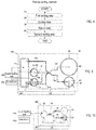
- the particle sorting method includes at least a first sorting step S1, a return step S2, and a second sorting step S3.
- the first sorting step S1 includes sending the sample 80 to the first flow path 10 of the micro flow path cartridge 100 and sorting the target particle-containing sample 81 from the sample 80 based on the signal corresponding to the target particles 91 passing through the detection region 11.
- the control unit 150 controls the liquid feeding unit 120 to feed the sample 80 from the upstream to the downstream of the first flow path 10.
- the detection unit 130 outputs a signal corresponding to the target particle 91 that has reached the detection region 11.
- the control unit 150 controls the sorting mechanism 140 so as to send the target particle-containing sample 81 that has reached the sorting region 12 to the first guide path 12a based on the signal from the detection unit 130.
- the control unit 150 controls the sorting mechanism 140 so as to send the sample that does not contain the target particles 91 that has reached the sorting region 12 to the second guide path 12b.
- the return step S2 includes returning the target particle-containing sample 81 sorted by the first sorting step to the first flow path 10 via the second flow path 20.
- the control unit 150 controls the liquid feeding unit 120 to send the target particle-containing sample 81 delivered to the first guide path 12a from the upstream to the downstream of the second flow path 20. In this way the target particle-containing sample 81 is returned upstream from the detection region 11 of the first flow path 10.
- the second sorting step S3 includes sending the returned target particle-containing sample 81 to the detection region 11 and the sorting region 12 and performing a sorting operation based on the signals corresponding to the target particles 91 passing through the detection region 11 .
- the control unit 150 controls the liquid feeding unit 120 to send the target particle-containing sample 81 from the upstream to the downstream of the first flow path 10.
- the detection unit 130 outputs a signal corresponding to the target particle 91 that has reached the detection region 11.
- the control unit 150 controls the sorting mechanism 140 so as to send the target particle-containing sample 81 that has reached the sorting region 12 to the first guide path 12a based on the signal from the detection unit 130.
- the control unit 150 controls the sorting mechanism 140 so as to send the sample that does not contain the target particles 91 that has reached the sorting region 12 to the second guide path 12b.
- the return step S2 and the second sorting step S3 may be further repeated.
- the first sorting step S1 and the second sorting step S3 can be repeated a plurality of times.
- the target particles 91 can be sorted with high purity even if the sample flows at a higher speed than compared to when the sorting process is performed only once, by performing the sorting operation a plurality of times. Therefore, the time required to sort the target particles 91 with sufficient purity can be shortened.
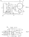
- micro flow path cartridge according to the present embodiment will be summarized with reference to FIG. 1 .
- the micro flow path cartridge 100 includes a flow path MC.
- the flow path MC is a tubular element through which a fluid can flow.
- the micro flow path cartridge 100 can sort the target particles 91 from the sample 80 containing a plurality of types of particles in the flow path MC.
- the micro flow path cartridge 100 includes a flow path forming body 40 in which the flow path MC for flowing a sample containing the target particles 91 is formed.
- the flow path forming body 40 is installed in the installation unit 110 of the particle sorter 200.
- Examples of the material of the flow path forming body 40 include glass, silicon, polydimethylsiloxane (PDMS), polymethylmethacrylate resin (PMMA), cyclic olefin resin (COC), cycloolefin polymer resin (COP), polyethylene terephthalate (PET), polycarbonate (PC), polytetrafluoroethylene (PTFE), metals and the like.
- PDMS polydimethylsiloxane
- PMMA polymethylmethacrylate resin
- COC cyclic olefin resin
- COP cycloolefin polymer resin
- PET polyethylene terephthalate
- PC polycarbonate
- PTFE polytetrafluoroethylene
- the flow path MC includes a first flow path 10 and a second flow path 20.
- the first flow path 10 has a detection region 11 for detecting the target particles 91 contained in the sample and a branched sorting region 12 for sorting the detected target particles 91.
- the detection region 11 is a part of the first flow path 10, and is located between the upstream end and the downstream end of the first flow path 10.
- the detection region 11 is arranged upstream of the sorting region 12.
- the detection region 11 is configured so that the target particles 91 can be externally detected by the detection unit 130 of the particle sorter 200.
- the detection region 11 has translucency and the target particles 91 in the flow path MC can be detected from outside the flow path MC.
- the sorting region 12 is a part of the first flow path 10, and is located between the upstream end and the downstream end of the first flow path 10.
- the sorting region 12 is arranged downstream of the detection region 11.
- the sorting region 12 is connected to the detection region 11 on the upstream side.
- the downstream side of the sorting region 12 branches into at least two flow paths.
- the sorting region 12 includes a first guide path 12a and a second guide path 12b extending downstream, respectively.
- the first guide path 12a and the second guide path 12b are connected to each other at the upstream end to form a branched path.
- the first guide path 12a directly or indirectly communicates with the second flow path 20.
- the first guide path 12a is a flow path through which the target particle-containing sample 81 flows.
- the second guide path 12b is not connected to the second flow path 20.
- the second guide path 12b is a flow path through which the non-target particles 92 flow.
- the second flow path 20 is provided to return the target particle-containing sample 81 containing the sorted target particles 91 to the upstream side of the detection region 11 of the first flow path 10.
- the liquid feeding direction in the second flow path 20 (from right to left in FIG. 1 ) is opposite to the liquid feeding direction in the first flow path 10 (from left to right in FIG. 1 ).
- the target particle-containing sample 81 containing the separated target particles 91 is sent to the upstream end of the second flow path 20.
- the upstream side of the second flow path 20 directly or indirectly communicates with the first guide path 12a.
- the downstream side of the second flow path 20 is directly or indirectly connected to the first flow path 10.
- the return position of the target particle-containing sample 81 from the second flow path 20 to the first flow path 10 is at least upstream of the detection region 11. In this way the target particle-containing sample 81 returned to the first flow path 10 is flowed again toward the downstream of the first flow path 10, so that the target particles 91 can be detected in the detection region 11 and and a sorting operation can be performed in the sorting region 12 based on the signal from the detection unit 130.
- the micro flow path cartridge 100 may also be provided with a valve structure for opening and closing the flow path MC in order to supply the liquid from the upstream to the downstream of the first flow path 10 and the liquid from the upstream to the downstream of the second flow path 20.
- a valve structure for opening and closing the flow path MC in order to supply the liquid from the upstream to the downstream of the first flow path 10 and the liquid from the upstream to the downstream of the second flow path 20.
- the valve structure may be an on/off valve that opens and closes (that is, communicates and shuts off) the flow path MC, or a check valve that prevents a flow (backflow) from downstream to upstream.
- the flow path MC also may be opened and closed by applying a pressing force from the outside to the portion of the flow path MC of the micro flow path cartridge 100 to deform the pressing portion. Therefore, the micro flow path cartridge 100 does not have to be provided with a valve structure.
- the micro flow path cartridge 100 includes the second flow path 20 so that the flow path MC returns the target particle-containing sample 81 containing the sorted target particles 91 upstream of the detection region 11 of the first flow path 10. In this way he sorting operation can be repeated a plurality of times using the second flow path 20. By performing the sorting operation a plurality of times, the target particles 91 can be sorted with high purity even if the sample flows at a higher speed than in the case where the sorting process is performed only once. As a result, the time required to sort the target particles 91 with sufficient purity can be shortened.
- the micro flow path cartridge 100 also may include a liquid reservoir for accommodating a liquid such as a sample 80 or a target particle-containing sample 81.
- the liquid reservoir can be, for example, a chamber, reservoir, well and the like.
- the flow path forming body 40 has a flat plate shape, and a tubular chamber is provided so as to rise from the main surface of the flat plate-shaped flow path forming body 40.
- the flow path forming body 40 is configured with a recovery chamber 51 for collecting the target particle-containing sample 81 sorted in the sorting region 12 of the first flow path 10.
- the recovery chamber 51 is connected to the downstream end of the first guide path 12a, which is one of the branched sorting regions 12.
- the target particle-containing sample 81 sent to the first guide path 12a is housed in the recovery chamber 51.
- the sorted target particle-containing sample 81 can be housed in the recovery chamber 51 and then sent to the second flow path 20 without being discharged to the outside. Since the target particle-containing sample 81 can be returned without being taken out to the outside, the sampling process can be performed without the risk of contamination even if the sampling operation is performed a plurality of times.
- the upstream end of the second flow path 20 communicates with the recovery chamber 51.
- the target particle-containing sample 81 can be directly sent from the recovery chamber 51 to the second flow path 20.
- the micro flow path cartridge 100 is formed with a sample chamber 52 for storing the sample 80 to be fed to the first flow path 10.
- the sample 80 previously injected and stored in the sample chamber 52 is supplied into the first flow path 10 by the liquid feeding unit 120 instead of supplying the sample 80 from the liquid feeding unit 120.
- the downstream end of the second flow path 20 communicates with the sample chamber 52.
- the control unit 150 controls the liquid feeding unit 120 so as to sort the target particle-containing sample 81 from the sample 80 (see FIG. 3 ) fed to the first flow path 10 from the sample chamber 52,and so that the sorted target particle-containing sample 81 is returned to the first flow path 10 via the second flow path 20 and the sample chamber 52.
- the sorted target particle-containing sample 81 can be housed in the sample chamber 52 that housed the original sample 80. That is, the liquid feeding of the original sample 80 in the first sorting operation and the liquid feeding of the target particle-containing sample 81 in the second and subsequent sorting operations can be performed with the same structure. Therefore, the structure and control of the particle sorter 200 can be simplified as compared with the case where the original sample 80 and the target particle-containing sample 81 are housed in separate chambers.
- the micro flow path cartridge 100 is formed with a waste chamber 55 for storing the sample 82 that has not been sorted as the target particle-containing sample 81 in the sorting region 12.
- the waste chamber 55 is connected to the downstream end of the second guide path 12b, which is the other end of the branched sorting region 12.
- the sample 80 sent to the second sorting 12b is housed in the waste chamber 55. In this way the sorting operation can be repeated a plurality of times without discharging the unsorted sample 82 to the outside.
- the particle sorter 200 does not come into contact with the sample, and a series of operations from injection of the sample 80 to multiple sorting and disposal can be completed in the micro flow path cartridge 100.
- the flow path forming body 40 includes a sample chamber 52 for storing a sample to be fed to the first flow path 10 , a reservoir 53 that communicates with the downstream end of the second flow path 20 (see FIG. 6 ), and a connecting flow path 53a connected to the first flow path 10 upstream of the detection region 11.
- the reservoir 53 is provided separately from the sample chamber 52.
- control unit 150 controls sorting mechanism 140 to sort the target particle-containing sample 81 from the sample 80 (see FIG. 6 ) sent from the sample chamber 52 to the first flow path 10 (see FIG. 1 ) and, as shown in FIG. 7 , controls the liquid feeding unit 120 to return the sorted target particle-containing sample 81 to the first flow path 10 via the second flow path 20, the reservoir 53, and the connecting flow path 53a. That is, in the first sorting step, the sample 80 is sent from the sample chamber 52 to the first flow path 10. The sorted target particle-containing sample 81 is accommodated in the reservoir 53 via the recovery chamber 51 and the second flow path 20. In the second sorting step, the target particle-containing sample 81 is sent from the reservoir 53 to the first flow path 10 via the connecting flow path 53a.
- the flow path forming body 40 includes a sheath liquid chamber 54 for storing sheath liquid and communicates with the sheath liquid chamber 54, and a sheath liquid flow path 54a connected upstream of the detection region 11 of the first flow path 10, that is, downstream of the confluence point with the connecting flow path 53a of the first flow path 10.
- the control unit 150 controls the liquid feeding unit 120 to send the sample 80 or the target particle-containing sample 81 to the first flow path 10, and send the sheath liquid from the sheath liquid chamber 54 to the first flow path via the sheath liquid flow path 54a.
- the sample flow is surrounded by the sheath liquid flow at the position of the detection region 11 of the first flow path 10.
- the particles in the sample can be aligned by the flow of the sheath liquid, so that the target particles 91 in the detection region 11 can be detected easily and with high accuracy.
- the sheath liquid flow path 54a is connected downstream from the confluence of the first flow path 10 and the connecting flow path 53a, the target particles can be aligned by the sheath liquid flow even when a sorting operation is performed on the target particle-containing sample 81 returned via the second flow path 20.
- the liquid amount of the target particle-containing sample 81 sent to the recovery chamber 51 by the first sorting step is smaller than the liquid amount of the initial sample 80 by the amount of the sample 82 sent to the waste chamber 55.
- the sorted target particle-containing sample 81 may be diluted.
- control unit 150 is configured to control the liquid feeding unit 120 so as to dilute the target particle-containing sample 81, and control the sorting mechanism 140 to perform a sorting operation with respect to the diluted target particle-containing sample 81.
- the liquid volume of the target particle-containing sample 81 can be increased by dilution, so that stable flow velocity control is possible even in the second and subsequent sorting operations. As a result, variations in sorting performance can be reduced.
- the control unit 150 controls the liquid feeding unit 120, detection unit 130, and sorting mechanism 140 to perform a dilution step S4 for diluting the target particle-containing sample 81 between the first sorting step S1 and the second sorting step S3. That is, in FIG. 8 , the particle sorting method of the present embodiment further includes a dilution step S4 for diluting the target particle-containing sample 81 between the first sorting step S1 and the second sorting step S3.
- the dilution step S4 may be performed before the return step S2 or after the return step S2.
- the control unit 150 controls the liquid feeding unit 120 so as to dilute the target particle-containing sample 81 in the recovery chamber 51. That is, after the first sorting step, the control unit 150 controls the liquid feeding unit 120 to send a predetermined amount of sheath liquid from the sheath liquid chamber 54 to the recovery chamber 51 via the sheath liquid flow path 54a, the first flow path 10, and the first guide path 12a. In this way uniform dilution is more easily accomplished, for example, compared to when diluting in the second flow path 20.
- the sheath liquid for dilution is stored in the recovery chamber 51 in advance before the first sorting step.
- the control unit 150 controls the liquid feeding unit 120 to dilute the target particle-containing sample 81 in the recovery chamber 51 by sending the target particle-containing sample 81 to the recovery chamber 51 that stores the diluting liquid.
- the target particle-containing sample 81 can be easily diluted simply by sending the sorted target particle-containing sample 81 to the recovery chamber 51. Since it is not necessary to transfer the dilution liquid between the sorting operation and the return operation of the target particle-containing sample 81 by the second flow path 20, the diluted target particles can be immediately sent after the initial sorting operation.
- the dilution liquid may be injected into the recovery chamber 51 by the user in advance when the micro flow path cartridge 100 is installed in the installation unit 110, or a step can be performed to send the dilution liquid from the sheath liquid chamber 54 (refer to FIG. 9 ) to the recovery chamber 51 before the first sorting step.
- control unit 150 also may control the liquid feeding unit 120 to send the dilution liquid from the sheath liquid chamber 54 to the reservoir 53 in FIG. 6 , to dilute the target particle-containing sample 81 stored in the reservoir 53.
- the sample 82 sent to the second guide path 12b may be returned to the upstream of the first flow path 10.
- the flow path forming body 40 is provided with a third flow path 30 configured to return the sample that was not sorted as the target particle-containing sample 81 in the sorting region 12 of the first flow path 10 to the upstream of the detection region 11 of the first flow path 10.
- the control unit 150 controls the liquid feeding unit 120 to return the sample 82 that was not sorted as the target particle-containing sample 81 in the sorting region 12 of the first flow path 10 to the upstream of the detection region 11 of the first flow path 10 to send the returned sample 82 to the detection region 11 of the first flow path 10, and controls the sorting mechanism 140 (refer to FIG. 1 ) to perform a sorting operation based on the signal from the detection unit 130 (refer to FIG. 1 ).
- the upstream end of the third flow path 30 is connected to the waste chamber 55.
- the flow path forming body 40 is provided with, in addition to the third flow path 30, a second reservoir 56 communicating with the downstream end of the third flow path 30, and a connection flow path 56a connecting the upstream of the detection region 11 of the first flow path 10 and the second reservoir 56.
- the downstream end of the third flow path 30 may be connected to the sample chamber 52 or the reservoir 53, or the downstream end of the third flow path 30 may be connected upstream of the detection region 11 of the first flow path 10.
- the flow path forming body 40 includes a plate-shaped substrate 41 and a sheet 42 bonded to the substrate 41.
- the flow path MC is formed by grooves formed on at least one of the sheet 42 side surface of the substrate 41 and the substrate 41 side surface of the sheet 42.
- a groove 42a is formed on the surface of the sheet 42 on the substrate 41 side, and the groove 42a is covered by the surface of the sheet 42 on the sheet 42 side to form a flow path MC having a tubular structure capable of flowing a liquid.
- the flow path forming body 40 can be configured with a simple structure in which the sheet 42 is simply attached to the substrate 41.
- the first flow path 10 and the second flow path 20 have, for example, a depth D of 1 ⁇ m or more and 1000 ⁇ m or less, and a width W of 1 ⁇ m or more and 1000 ⁇ m or less.
- the particle sorter 200 of the present embodiment is particularly suitable for a micro flow path cartridge 100 having such a micro flow path.
- liquid reservoirs such as the sample chamber 52, the recovery chamber 51, the sheath liquid chamber 54, and the reservoir 53 are formed on the main surface of the substrate 41 opposite to the sheet 42.
- the substrate 41 is formed with through holes 41a that penetrate the substrate 41 in the thickness direction from the main surface to the surface on the sheet 42 side.
- the through hole 41a connects the inner bottom portion of the liquid reservoir such as the sample chamber 52, the recovery chamber 51, the sheath liquid chamber 54, and the reservoir 53 with the flow path MC (groove portion 42a of the sheet 42).
- the liquid inside the liquid reservoir is allowed to flow through the through hole 41a to the flow path MC by applying pressure to the upper surface opening side of the liquid reservoir such as the sample chamber 52, the recovery chamber 51, the sheath liquid chamber 54, and the reservoir 53.
- the sheet 42 is made of a material that is more flexible than the substrate 41 and can be elastically deformed by pressing.
- the substrate 41 is a glass substrate and the sheet 42 is a PDMS sheet.
- the sorting region 12 of the first flow path 10 is configured so that the flow path MC can be blocked by pressing the sheet 42 from the outside.
- the sorting mechanism unit 140 has a pressing part 142a that can move in the direction of approaching and separating from the sheet 42. The sheet 42 is pressed by the pressing part 142a.
- the flow path can be easily opened and closed simply by applying a pressing force from the outside to the sheet 42 that covers the flow path portion of the sorting region 12. Then, the target particles 91 that have reached the sorting region 12 can be easily sorted by opening and closing the flow path.
- the sorting mechanism 140 includes a flow path opening/closing unit 141 that opens and closes at least one of the branched flow paths in the sorting region 12 of the first flow path 10. In this way the sorting mechanism 140 can be constructed with a compact configuration in which the flow path opening/closing unit 141 is provided, so that the structure of the particle sorter 200 can be simplified.
- the sorting region 12 of the first flow path 10 is bifurcated into a first guide path 12a that guides the sample to the collection chamber 51 and a second guide path 12b that is different from the first guide path.
- the flow path opening/closing unit 141 is provided one by one in the first guide path 12a and the second guide path 12b.
- the control unit 150 is configured to control the sorting mechanism 140 so as to distribute the sample 80 and the target particle-containing sample 81 sent to the sorting region 12 to the first guide path 12a based on the signal from the detection unit 130 (see FIG. 1 ).
- the sorting mechanism 140 is configured by a flow path switching mechanism that distributes the flow of the sample to either the first guide path 12a or the second guide path 12b. Since the sorting operation can be performed by just switching the flow path, the configuration of the sorting mechanism 140 can be simplified.
- the flow path opening/closing unit 141 is a pinch valve.
- the flow path opening/closing unit 141 is configured to close at least one of the branched flow paths by deforming the region in which at least one of the branched flow paths of the micro flow path cartridge 100 is formed by pressing from the outside.
- the flow path opening/closing unit 141 can be configured with a simple structure of simply pressing the micro flow path cartridge 100 from the outside. Since the flow path opening/closing unit 141 does not come into contact with the liquid inside the micro flow path cartridge 100, contamination can be prevented.
- FIGS. 16 to 22 show a structural example of the flow path opening/closing unit 141.
- the sheet 42 which is the lower surface of the flow path forming body 40, is shown upside down so as to be located on the upper side in the drawing.
- the flow path opening/closing unit 141 includes a displacement-enhancing type piezoelectric actuator.
- the flow path MC can be opened and closed at high speed by the highly responsive piezoelectric actuator, so that it is possible to prevent particles other than the target particles 91 from being mixed into the sorted sample.
- the piezoelectric actuator has a drawback in that the amount of displacement that can be generated is small, but since the amount of displacement can be increased by the displacement-enhancing type piezoelectric actuator, the flow path MC can be opened and closed reliably even when the flow path MC of the micro flow path cartridge 100 is pressed from the outside.
- the displacement-enhancing type piezoelectric actuator includes a movable member 142 having a pressing portion 142a facing the pressing position of the micro flow path cartridge 100, a piezoelectric element 143 that moves the movable member 142, and a fixing member 144 which holds the piezoelectric element 143 and the movable member 142.
- the movable member 142 is configured to displace the pressing portion 142a by a displacement amount larger than the displacement amount of the piezoelectric element 143.
- the displacement amount of the pressing portion 142a required to reliably open and close the flow path MC of the micro flow path cartridge 100 can be easily obtained by expanding the displacement of the piezoelectric element 143 via the movable member 142.
- one end of the piezoelectric element 143 extending vertically is fixed to the fixing member 144.
- a contact member 143a that comes into contact with the movable member 142.
- the piezoelectric element 143 is a so-called stack type piezoelectric actuator in which a plurality of piezoelectric bodies are laminated in the displacement generation direction.
- the piezoelectric element 143 expands and contracts in the vertical direction, which is the stacking direction, when a voltage is applied.
- the movable member 142 is arranged on the other end side of the piezoelectric element 143 so as to come into contact with the contact member 143a.
- the movable member 142 has a cantilever structure extending from the fixing member 144 along the sheet 42 of the flow path forming body 40.
- the movable member 142 has a straight plate-like shape.
- a pressing portion 142a is provided at the tip of the movable member 142 in a convex shape toward the sheet 42.
- the contact member 143a is arranged so as to come into contact with the movable member 142 at a position between the fixed end of the movable member 142 and the pressing portion 142a.
- the fixing member 144 is provided on the lower surface (upper surface in FIG. 17 ) of the installation unit 110.
- the pressing portion 142a closes the flow path MC by pushing up from beneath the sheet 42, which is the lower surface of the flow path forming body 40 exposed from the opening of the installation unit 110.
- a pressing portion 142a is formed at one end of the movable member 142, and the contact member 143a of the piezoelectric element 143 is arranged at the other end of the movable member 142.
- the fixing member 144 rotatably holds the movable member 142 at a position between the pressing portion 142a and the contact member 143a.
- the displacement of the piezoelectric element 143 is increased only by a ratio (L3/L4) of the length L3 from the contact member 143a to the holding position (fulcrum) and the length L4 from the holding position (fulcrum) to the pressing portion 142a. Note that L3 ⁇ L4.
- the piezoelectric actuator also may be provided with an energizing member 145 that energizes the movable member 142 in the direction in which the pressing portion 142a releases the pressing.
- an energizing member 145 that energizes the movable member 142 in the direction in which the pressing portion 142a releases the pressing.
- displacement-enhancing piezoelectric actuator structures There are various types of displacement-enhancing piezoelectric actuator structures, and the structure is not limited to a specific structure. In the following, variations of the displacement-enhancing type piezoelectric actuator will be illustrated.
- the movable member 142 has a pressing portion 142a at the tip and support portions 142b and 142c branched in a Y shape at the other end side.
- One support portion 142b is supported by the fixing member 144 via an elastic hinge 146.
- the other support portion 142c is connected to the piezoelectric element 143 via an elastic hinge 146. In this way the movable member 142 is pressed via the elastic hinge 146, and the pressing portion 142a is displaced toward the sheet 42 side when the piezoelectric element 143 is extended.
- the movable member 142 has a pressing portion 142a at the tip and Y-shaped support portions 142d and 142e at the other end side.
- the pair of support portions 142d and 142e are annularly connected via a plurality of elastic hinges 146.
- the piezoelectric element 143 is arranged inside the annular portion, and both ends are connected to separate elastic hinges 146. In this way the movable member 142 is pressed via the elastic hinges 146 at both ends, and the pressing portion 142a is displaced toward the sheet 42 side when the piezoelectric element 143 contracts.
- FIGS. 23 to 26 A more specific structural example of the particle sorter 200 of the present embodiment will be described with reference to FIGS. 23 to 26 .
- the micro flow path cartridge 100 installed in the particle sorter 200 will be described by taking the configurations shown in FIGS. 5 and 6 as an example.
- Sample 80 is, for example, diluted and fluorescently labeled blood
- the target particle 91 is, for example, fluorescently labeled blood cells.
- the micro flow path cartridge 100 sorts the target cells, which are the target particles 91, from cells other non-target cells, which are the non-target particles 92.
- Target cells are rare cells that circulate in the blood.
- the target cells are circulating cancer cells (CTCs) in the blood
- the non-target cells are red blood cells, white blood cells, platelets and the like.
- the installation unit 110 includes a cartridge holder 111 and a cover member 112.
- the installation unit 110 detachably supports the micro flow path cartridge 100.
- the micro flow path cartridge 100 is a disposable consumable part.
- the micro flow path cartridge 100 is installed in the installation unit 110 by the user and is used in a sorting process. When the sorting process is completed, the micro flow path cartridge is removed from the installation unit 110. When a sorting process is performed on another sample 80, a new micro flow path cartridge 100 is installed in the installation unit 110.
- the cartridge holder 111 has a bottom portion 111a that supports the peripheral edge portion of the micro flow path cartridge 100 from below.
- the bottom portion 111a has a frame-like shape with an opening (see FIG. 17 ) at the center so as to expose the formed portions of the flow path MC such as the detection region 11 and the sorting region 12 of the micro flow path cartridge 100 downward.
- the cartridge holder 111 has a wall-shaped side surface portion 111b that rises upward from the outer peripheral portion of the bottom portion 111a.
- the cover member 112 is detachably attached (or can be opened and closed) on the upper surface of the cartridge holder 111.
- the cover member 112 is provided so as to cover the upper surface opening of the liquid reservoir in the micro flow path cartridge 100 held by the cartridge holder 111. That is, the cover member 112 seals the upper surface openings of the sample chamber 52, the recovery chamber 51, the reservoir 53, the waste chamber 55, and the sheath liquid chamber 54 of the micro flow path cartridge 100.
- a seal member for air-tightly sealing the upper surface opening is provided on the lower surface of the cover member 112.
- the cover member 112 is formed with one communication hole 112a for each of the sample chamber 52, the recovery chamber 51, the reservoir 53, the waste chamber 55, and the sheath liquid chamber 54.
- the communication hole 112a penetrates the cover member 112 in the thickness direction.
- Each communication hole 112a is connected to the liquid feeding unit 120 one by one on the upper surface of the cover member 112 via a pipe member 121 (see FIG. 26 ) described later.
- a sorting mechanism 140 is provided below the installation unit 110.
- the sorting mechanism 140 includes a base member 147 attached to the lower surface of the cartridge holder 111, and a flow path opening/closing unit 141 provided on the base member 147.
- the liquid feeding unit 120 also includes a liquid feeding control valve 122 for switching the liquid flow path in the micro flow path cartridge 100 to control the liquid feeding path. These liquid feed control valves 122 are also provided on the base member 147.
- the flow path opening/closing unit 141 is composed of a pinch valve provided with a displacement-enhancing piezoelectric actuator (see FIG. 17 ).
- the flow path opening/closing unit 141 is provided so as to project downward from the base member 147.
- the flow path opening/closing unit 141 closes the flow path MC by pressing the sheet 42, which is the lower surface of the flow path forming body 40, upward so that the pressing portion 142a pushes up from below.
- the flow path opening/closing unit 141 is provided one by one corresponding to the first guide path 12a and the second guide path 12b (see FIG. 25 ) downstream of the sorting region 12.
- the two flow path opening/closing units 141 are provided so that the opening/closing position P1 of the first guide path 12a and the opening/closing position P2 of the second guide path 12b in FIG. 25 can be closed by pressing, respectively.
- the liquid feed control valve 122 provided on the base member 147 is also comprised of a pinch valve that closes the flow path MC by pressing and deforming the sheet 42 of the flow path forming body 40, similar to the flow path opening/closing unit 141. Therefore, the liquid feed control valve 122 is provided so as to face upward with respect to the lower surface of the micro flow path cartridge 100.
- the liquid feed control valve 122 is a cylinder valve of a type in which the pressing portion is operated by an air cylinder, unlike the flow path opening/closing unit 141.
- a plurality of liquid feed control valves 122 are provided on the flow path MC so that the flow path of the micro flow path cartridge 100 can be switched according to the processing step.
- each liquid feed control valve 122 is provided with a switching position P3 upstream of the connection position with the connection flow path 53a in the first flow path 10, switching position P4 on one sheath liquid flow path 54a and switching position P5 on the other sheath liquid flow path 54a, a switching position P6 on the second flow path 20 and a switching position P7 on the connection flow path 53a.
- the liquid feed control valve 122 at any position is turned on, the liquid feed control valve 122 presses the sheet 42 to close the corresponding flow path.
- the liquid feed control valve 122 is turned off, the pressing of the sheet 42 by the liquid feed control valve 122 is released, and the corresponding flow path is opened.
- the liquid feed control valve 122 is not provided on the first guide path 12a and the second guide path 12b. That is, the first guide path 12a at the opening/closing position P1 and the second guide path 12b at the opening/closing position P2 are opened and closed by the corresponding flow path opening/closing units 141, respectively.
- the flow path opening/closing unit 141 is configured to perform not only the sorting operation but also the opening/closing of the flow path for controlling the liquid feed.
- the liquid feeding unit 120 is individually connected to each liquid reservoir (collection chamber 51, sample chamber 52, reservoir 53, sheath liquid chamber 54, waste chamber 55) of the micro flow path cartridge 100 via the pipe member 121.
- the liquid feeding unit 120 includes the plurality of liquid feeding control valves 122 described above.
- the liquid feeding unit 120 is configured to supply liquid to the flow path MC of the micro flow path cartridge 100 by applying pressure under the control of the control unit 150.
- the liquid feeding unit 120 can individually apply positive pressure to the recovery chamber 51, the sample chamber 52, the reservoir 53, the sheath liquid chamber 54, and the waste chamber 55 to send the internal liquid to the flow path MC.
- the liquid feeding unit 120 can individually open the recovery chamber 51, the sample chamber 52, the reservoir 53, the sheath liquid chamber 54, and the waste chamber 55 to the atmosphere to accommodate the liquid sent from the flow path MC inside.
- the liquid feeding unit 120 may include an air pressure source 123 such as an air pump, a pressure regulator (regulator) 124, and a pressure supply unit 125.
- the liquid feeding unit 120 adjusts the liquid feeding speed from each chamber and reservoir by adjusting the pressure supplied from the air pressure source 123 by the pressure regulator 124 under the control of the control unit 150.
- the pressure supply unit 125 includes a multi-port valve terminal capable of individually controlling the on and off of the pressure supply to each liquid feed control valve 122. Under the control of the control unit 150, the liquid feed unit 120 individually switches the pressure supply from the air pressure source 123 on and off for each liquid feed control valve 122 by the pressure supply unit 125, so that each liquid feed control valve 122 operates individually.
- the detection unit 130 is provided below the installation unit 110.
- the detection unit 130 detects the target particles 91 from the lower surface side on which the sheet 42 is arranged in the flow path forming body 40.
- the detection unit 130 is configured to optically detect the target particles 91 passing through the detection region 11.
- the base member 147 is configured with a notch-shaped penetrating portion 147a over a range including the detection region 11 and the sorting region 12 in which the pressing portion 142a is arranged.
- the detection unit 130 detects the target particles 91 passing through the detection region 11 from below the base member 147 via the region LP of the penetration portion 147a.
- the detection unit 130 includes a light source 131, an optical system 132, and a photodetector 133.
- the light source 131 generates excitation light for the fluorescent label bound to the target particles 91.
- the light source 131 is composed of, for example, a semiconductor laser element.
- the optical system 132 includes an objective lens 132a and dichroic mirrors 132b and 132c.
- the photodetector 133 is configured to detect fluorescence generated from a fluorescent label excited by excitation light, and output a signal according to the fluorescence intensity.
- the photodetector 133 is a photon counter.
- a photomultiplier tube or an MPPC multi-pixel photon counter
- the excitation light emitted from the light source 131 is reflected by the dichroic mirror 132b, passes through the objective lens 132a, and irradiates the detection region 11.
- fluorescence is generated from the fluorescent label.
- the fluorescent light passes through the objective lens 132a and the dichroic mirror 132b, is reflected by the dichroic mirror 132c, and is detected by the photodetector 133.
- the detection unit 130 detects the fluorescence generated by irradiating the target particles 91 with the excitation light, the detection unit 130 outputs an electric signal corresponding to the detected fluorescence.
- the control unit 150 is composed of, for example, a CPU.
- the control unit 150 performs various processes based on a program stored in the storage unit 151.
- the storage unit 151 is composed of a RAM, a ROM, a hard disk and the like.
- the control unit 150 controls the liquid feeding unit 120 so that the sample chamber 52, the recovery chamber 51, the reservoir 53, the waste chamber 55, and the sheath liquid chamber 54 are individually pressurized or opened to the atmosphere.
- the control unit 150 switches the liquid feeding path of the liquid by controlling the liquid supply control valve 122 of the liquid supply unit 120 and the flow path opening/closing unit 141 to open and close each position on the flow path MC.
- the control unit 150 is individually connected to the two flow path opening/closing units 141 via the driver circuit 152.
- the control unit 150 applies a predetermined operating voltage from the driver circuit 152 to the piezoelectric element 143 of the flow path opening/closing unit 141. In this way the flow path MC is closed as a result of the displacement of the pressing portion 142a due to the expansion and contraction operation of the piezoelectric element 143.
- the control unit 150 stops the voltage application from the driver circuit 152 to the piezoelectric element 143 of the flow path opening/closing unit 141. In this way the pressing portion 142a releases the pressure on the sheet 42, and the flow path MC is opened.
- the control unit 150 individually controls each liquid supply control valve 122 arranged at the switching position P3 to the switching position P7 (see FIG. 25 ) via the pressure supply unit 125 of the liquid feeding unit 120.
- the control unit 150 performs controls for carrying out the particle sorting method of the present embodiment. That is, as shown in FIG. 2 , the control unit 150 controls the liquid feeding unit 120, the detection unit 130, and the sorting mechanism 140 to perform first sorting step S1, the return step S2, and the second sorting step S3.
- the first sorting step S1 is a step sorting the target particle-containing sample 81 by controlling the liquid feeding unit 120 so as to feed the sample 80 to the first flow path 10 of the micro flow path cartridge 100, and sorting the target particle-containing sample 81 by controlling the the sorting mechanism 140 to perform a sorting operation based on the signal from the detection unit 130.
- the return step S2 is a step of controlling the liquid feeding unit 120 so that the target particle-containing sample 81 sorted by the first sorting step S1 is returned to the first flow path 10 via the second flow path 20.
- the second sorting step S3 is a step of controlling the liquid feeding unit 120 to send the returned target particle-containing sample 81 to the detection region 11 and sorting region 12 of the first flow path 10, and controlling the sorting mechanism 140 to perform a sorting operation based based on the signal from the detection unit 130.
- the first sorting step S1 is performed on the sample 80 and the second sorting step S3 is successively performed on the target particle-containing sample 81 sorted by the first sorting step S1 within the micro flow path cartridge 100 by performing the return step S2.
- the control unit 150 controls the liquid feeding unit 120 and the sorting mechanism 140 so as to further perform the dilution step S4.
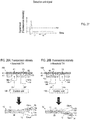
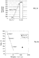
- the control unit 150 sends liquid by the liquid feeding unit 120 and acquires a signal from the detection unit 130. Even if the non-target particles 92 are irradiated with excitation light when the non-target particles 92 in the sample 80 pass through the detection region 11, the fluorescence of a specific wavelength due to the fluorescent label of the target particles 91 does not occur. When the target particles 91 in the sample 80 pass through the detection region 11, the fluorescent label is excited by the excitation light, and the generated fluorescence of a specific wavelength is detected by the detection unit 130. As a result, as shown in FIG. 27 , the signal of the detection unit 130 has a rise (peak) of the fluorescence intensity of a specific wavelength.
- the control unit 150 determines that the target particles 91 have been detected when the detected fluorescence intensity is equal to or higher than a preset threshold value TH. When the detected fluorescence intensity is less than the threshold value TH, the control unit 150 determines that the target particles 91 have not been detected.
- the control unit 150 closes the first guide path 12a (opening/closing position P1) by the flow path opening/closing unit 141 of the first guide path 12a, and the flow path opening/closing unit 141 of the second guide path 12b opens the second guide path12b (opening/closing position P2). In this way the non-target particles 92 are sent to the second guide path 12b.
- the control unit 150 causes the flow path opening/closing unit 141 of the first guide path 12a to open the first guide path 12a, and flow path opening/closing unity 141 of the second guide path 12b is closed by the flow path opening closing unit 141 of 12b. In this way the target particles 91 are sent to the first guide path 12a.
- the control unit 150 controls the flow path opening/closing unit 141 to open the first guide path 12a and close the second guide path 12b at the timing when the time t1 elapses after the fluorescence intensity equal to or higher than the threshold value TH is detected. Then, the control unit 150 keeps the state in which the first guide path 12a is open and the second guide path 12b is closed for a predetermined time t2.
- the predetermined time t2 is a margin time for the target particles 91 that have reached the sorting region 12 to reliably pass through the opening/closing position P1 by the flow path opening/closing unit 141 based on the flow velocity in the first flow path 10.
- the sample 81 containing target particles to be sorted contains sample components (that is, target particles 91, non-target particles 92, and liquid phase) that have passed through the opening/closing position P1 by the flow path opening/closing unit 141 during a predetermined time t2.
- sample components that is, target particles 91, non-target particles 92, and liquid phase
- the control unit 150 controls the flow path opening/closing unit 141 so as to close the first guide path 12a and open the second guide path 12b.
- FIGS. 29 and 30 the structures other than the micro flow path cartridge 100 shall be referred to with reference to FIGS. 23 to 26 .
- the user injects the sample 80 into the sample chamber 52 of the new micro flow path cartridge 100, and injects the sheath liquid into the sheath liquid chamber 54.
- the user installs the micro flow path cartridge 100 in the installation unit 110 and attaches the cover member 112. This prepares for the sorting process. Thereafter, the sorting process operation by the particle sorter 200 is started according to the operation input of the user.
- the control unit 150 starts the first sorting step S1 (see FIGS. 8 and 31A ).
- step S11 as shown in FIG. 31A , the control unit 150 executes a process of feeding the sample 80 of the sample chamber 52 and the sheath liquid of the sheath liquid chamber 54 to the first flow path 10.
- the control unit 150 causes each liquid feed control valve 122 to operate so as to open the flow paths of the switching position P3, the switching position P4, and the switching position P5, and close the flow paths of the switching position P6 and the switching position P7.
- the control unit 150 controls the liquid feeding unit 120 so as to apply positive pressure to the sample chamber 52 and the sheath liquid chamber 54 to open the recovery chamber 51, the waste chamber 55, and the reservoir 53 to the atmosphere.
- the sample 80 is sent from the sample chamber 52 to the first flow path 10
- the sheath liquid is sent from the sheath liquid chamber 54 to the first flow path 10 via the sheath liquid flow path 54a.
- the feeding of the sample and the sheath liquid is continued until the first sorting step S1 is completed.
- step S12 the control unit 150 detects the target particles 91 based on the signal of the detection unit 130. Since the liquid feeding is continued, the sample 80 flowing through the first flow path 10 passes through the detection region 11. When the target particle 91 is not detected in the detection region 11 (step S12: NO), the fluorescence intensity obtained from the signal of the detection unit 130 does not reach the threshold value TH, so that the control unit 150 closes the first guide path 12a and controls the flow path opening/closing unit 141 so as to maintain the state in which the second guide path 12b is open. The control unit 150 continues the detection process in step S12. The unsorted sample 82 is sent to the waste chamber 55 via the second guide path 12b.
- step S12 when the target particle 91 passes through the detection region 11, the fluorescence intensity obtained from the signal of the detection unit 130 becomes equal to or higher than the threshold value TH (see FIG. 27 ) (step S12: YES).
- the control unit 150 executes a process of sorting the target particle-containing sample 81 into the first guide path 12a in step S13. Specifically, the control unit 150 controls the flow path opening/closing unit 141 so as to open the first guide path 12a and close the second guide path 12b. In this way the target particle-containing sample 81 is sorted into the first guide path 12a.
- step S14 the control unit determines whether the entire amount of the sample 80 in the sample chamber 52 has been sent to the first flow path 10. If the entire amount of the sample 80 in the sample chamber 52 has been sent to the first flow path 10 (step S14: YES), the process proceeds to step S4 (see FIG. 8 ). If the entire amount of the sample 80 in the sample chamber 52 has not been sent to the first flow path 10 (step S14: NO), the process is returned to step S12.
- the time required for sending the entire amount of liquid is calculated from the volume of the sample and the liquid feeding speed can be determined beforehand, then determined whether the elapsed time from the start of liquid feeding of the sample has reached the calculated time.
- the first sorting step S1 is performed.
- the first sorting step S1 is carried out until the total amount of the sample 80 in the sample chamber 52 has been transferred. After the completion of the first sorting step S1, all the target particle-containing sample 81 sorted into the first guide path 12a is stored in the recovery chamber 51.
- control unit 150 performs a dilution step S4 (see FIG. 8 ) for diluting the target particle-containing sample 81 by sending the sheath liquid to the recovery chamber 51.
- control unit 150 causes each liquid feed control valve 122 to operate to open the flow paths of the switching position P4 and the switching position P5, and close the flow paths of the switching position P3, the switching position P6, and the switching position P7.
- the control unit 150 controls the flow path opening/closing unit 141 so as to maintain the state in which the first guide path 12a is open and the second guide path 12b is closed.
- the control unit 150 controls the liquid supply unit 120 so as to apply a positive pressure to the sheath liquid chamber 54 to open the sample chamber 52, the recovery chamber 51, the waste chamber 55, and the reservoir 53 to the atmosphere. In this way the sheath liquid from the sheath liquid chamber 54 is sent to the recovery chamber 51 through the sheath liquid flow path 54a, the detection region 11, and the first guide path 12a.
- the control unit 150 continues to send the sheath liquid at a predetermined flow rate for a predetermined time, so that a preset amount of the sheath liquid is accommodated in the recovery chamber 51 as a diluted liquid.
- the target particle-containing sample 81 is diluted to a predetermined concentration.
- the dilution step S4 may be executed before the first sorting step S1. In this way the target particle-containing sample 81 and the sheath liquid can be mixed more effectively in the recovery chamber 51.
- step S2 the control unit 150 controls the liquid feeding unit 120 so that the diluted target particle-containing sample 81 in the recovery chamber 51 is returned upstream of the detection region 11 of the first flow path 10.
- the control unit 150 causes each liquid feed control valve 122 to operate to open the flow path at the switching position P6 and close the flow paths at the switching position P3, the switching position P4, the switching position P5, and the switching position P7.
- the control unit 150 controls the flow path opening/closing unit 141 so as to close the first guide path 12a.
- the control unit 150 applies a positive pressure to the recovery chamber 51 to control the liquid supply unit 120 so as to open the sample chamber 52, the sheath liquid chamber 54, the waste chamber 55, and the reservoir 53 to the atmosphere. In this way the diluted target particle-containing sample 81 in the recovery chamber 51 is sent to the reservoir 53 through the second flow path 20.
- the control unit 150 causes the entire amount of the target particle-containing sample 81 in the recovery chamber 51 to be stored in the reservoir 53.
- the time required to feed all the liquid in the recovery chamber 51 can calculated beforehand from the storage capacity of the recovery chamber 51 and the liquid feed velocity, and the total amount of the liquid in the recovery chamber 51 may be sent from the recovery chamber 51 for a period longer than the calculated time in order to store the entire amount of the diluted target particle-containing sample 81 in the recovery chamber 51 to the reservoir 53.
- step S31 the control unit 150 executes a process of feeding the target particle-containing sample 81 of the reservoir 53 and the sheath liquid of the sheath liquid chamber 54 to the first flow path 10.
- the control unit 150 causes each liquid feed valve 122 to operate to open the flow paths of the switching position P4, the switching position P5, and the switching position P7, and close the flow paths of the switching position P3 and the switching position P6.
- the control unit 150 controls the liquid supply unit 120 so as to apply positive pressure to the reservoir 53 and the sheath liquid chamber 54 to open the sample chamber 52, the recovery chamber 51, and the waste chamber 55 to the atmosphere. In this way the target particle-containing sample 81 is sent from the reservoir 53 to the first flow path 10 via the connection flow path 53a, and the sheath liquid is sent from the sheath liquid chamber 54 to the first flow path 10 via the sheath liquid flow path 54a.
- the content of the detection and sorting operations in the second sorting step S3 are the same as those in the first sorting step S1. That is, as shown in FIG. 31B , the control unit 150 executes the detection process (step S32), the sorting process (step S33), and the total liquid feed determination process (step S34).
- the detection process (step S32), the sorting process (step S33), and the total liquid feed determination process (step S34) are the same processes of step S12, step S13, and step S14 in the first sorting step S1 of FIG. 31A , respectively, detailed description thereof will be omitted. As shown in FIG.
- the control unit 150 controls the flow path opening/closing unit 141 so as to open the first guide path 12a and close the second guide path 12b.
- the control unit 150 switches to a state in which the first guide path 12a is closed and the second guide path 12b is opened. In this way the target particle-containing sample 81 is again dispensed into the first guide path 12a.
- the second sorting step S3 is carried out until the total amount of the target particle-containing sample 81 in the reservoir 53 has been transferred. After the completion of the second sorting step S3, all the target particle-containing samples 81 re-sorted into the first guide path 12a are stored in the recovery chamber 51.
- the number of non-target particles 92 is significantly reduced as compared with the sample 80 in the first sorting step S1. Therefore, in the second sorting step S3, the non-target particles 92 mixed in the target particle-containing sample 81 are further removed, and the purity of the target particles 91 in the target particle-containing sample 81 is increased.
- the liquid feeding velocity in the second sorting step S3 may be the same as the liquid feeding velocity in the first sorting step S1, or may be different from the liquid feeding velocity in the first sorting step S1.
- the control unit 150 may control the liquid feeding unit 120 so that the flow velocity of the sample in the first sorting step S1 is greater than the flow velocity of the target particle-containing sample 81 in the second sorting step S3.
- the flow velocity of the target particle-containing sample 81 in the second sorting step S3 may be lower than the flow velocity of the sample in the first sorting step S1.
- the flow velocity of the target particle-containing sample 81 can be adjusted by controlling the pressure regulator 124 and changing the magnitude of the positive pressure supplied to the first flow path 10.
- the first sorting step S1 can be completed in a short time.
- the sorting accuracy can be improved by feeding the liquid at a relatively low flow velocity.
- the purity of the target particles can be effectively improved while shortening the time required for sorting.
- the target particle 91 is sorted by the particle sorter 200 of the present embodiment.
- the first sorting step S1 and the second sorting step S3 are performed a total of two sorting steps, but the sorting step may be performed three or more times.
- the third and subsequent sorting steps are a repetition of the dilution step S4, the return step S2, and the second sorting step S3.
- the purity of the target particles 91 and required time were measured when a first sorting process and a second sorting process (that is, a total of two sorting steps) were performed by the particle sorter of the embodiment using the micro flow path cartridge 100 shown in FIG. 25 .
- Target particles Green fluorescent beads (15 ⁇ m in diameter, manufactured by Thermo Scientific)
- Non-target particles Red fluorescent beads (3.2 ⁇ m in diameter, manufactured by Thermo Scientific)
- Sheath liquid Ultrapure water containing 2% surfactant
- the volume of the sample, the concentration and number of total particles (total of target particles and non-target particles), the number of target particles, and the purity of the target particles are shown in Table 1 below.
- Table 1 Example Before-sorting sample Volume [ ⁇ L] Total particles Target particles Purity [%] Concentration [particles/mL] Quantity [particles] Quantity [particles] 100 1.17 ⁇ 10 8 1.17 ⁇ 10 7 653 0.0056
- the purity of the target particles (number of target particles/total number of particles).
- the purity (0.0056%) of the target particles in the sample assumes a sorting process using rare particles having an extremely small content in the sample, such as CTC in the blood sample, as the target particles.
- the sorting process by the particle sorter 200 was carried out under the following conditions.
- Comparative Example 1 and Comparative Example 2 For comparison with the Example, in Comparative Example 1 and Comparative Example 2, only one sorting step was carried out using the same micro flow path cartridge as in Example. Therefore, in Comparative Example 1 and Comparative Example 2, the second flow path 20 and the reservoir 53 are not used.
- the particle sorter 200 used in Comparative Example 1 and Comparative Example 2 was also the same as in the above-mentioned Example.
- Table 3 shows the volume of the sample, the concentration and number of total particles (total of target particles and non-target particles), the number of target particles, and the purity of the target particles in Comparative Example 1 and Comparative Example 2.
- Table 3 Comparative Example Before-sowing sample Volume [ ⁇ L] Total particles Target particles Purity [%] Concentration [particles/mL] Quantity [particles] Quantity [particles] Comp. Ex. 1 100 1.0.51 ⁇ 10 6 1.051 ⁇ 10 5 613 0.58 Comp. Ex. 2
- Comparative Example 1 and Comparative Example 2 the concentration of the total particles was diluted to 1/100 as compared with the above-mentioned Example.
- the purity of the target particles in the before-sorting sample was 0.58%.
- Comparative Example 1 the purity of the target particles was 29.4%, and in Comparative Example 2, the purity of the target particles was 37.9%. Therefore, in Comparative Example 1 and Comparative Example 2, almost the same results as those in the above-mentioned Examples were obtained with respect to the purity of the sorted target particles.
- Comparative Example 1 the processing time was 343 seconds, and in Comparative Example 2, the processing time was 570 seconds.
- the throughput of Comparative Example 1 was 306 (event/sec), and the throughput of Comparative Example 2 was 185 (event/sec).
- Throughput is a simple example of this result. It can be seen that in the above embodiment, 8114 particles are processed per second, whereas in Comparative Example 1, only 306 particles are processed per second, and in Comparative Example 2, only 185 particles are processed per second. As shown in FIG. 34 , the throughput of the Example is about 27 times that of the Comparative Example 1. From the above, it was confirmed that the particle sorter 200, the particle sorting method, and the micro flow path cartridge 100 of the present embodiment can shorten the time required for sorting the target particles with sufficient purity.
- Comparative Example 3 As shown in Table 5 below, the sorting process was performed only once using three types of before-sorting samples (Sample 1, Sample 2, and Sample 3) in which the ratio of the target particles was adjusted to a constant value and the concentrations of the total particles were different were used. For each sample, the experimental conditions of the sorting step are the same as those of Comparative Example 1 and Comparative Example 2. Table 5: Comparative Example 3 Sample 1 Sample 2 Sample 3 Total particle concentration [particles/mL] 603310 301655 150827 Target particle ratio [%] 0.53% 0.53% 0.53% Volume [ ⁇ L] 200 400 800 Processing time [sec] 326 717 1221 Throughput [event/sec] 370 168 99 Purity [%] 26.8 57.6 80.3
- Sample 2 is a 2-fold dilution of Sample 1.
- Sample 3 is a 2-fold dilution of Sample 2. Since the samples diluted 2-fold are processed under the same experimental conditions, the throughput of sample 2 is about 1/2 that of sample 1 and that of sample 3 is about 1/2 that of sample 2. As can be seen from Table 5, the purity of Sample 1 was 26.8%, that of Sample 2 was 57.6%, and that of Sample 3 was 80.3%.
- FIG. 35 A graph plotting the relationship between the throughput and the obtained purity for Samples 1 to 3 is shown in FIG. 35 .
- the vertical axis is the purity of the target particles and the horizontal axis is the throughput.
- the trade-off relationship as shown in FIG. 35 is established between the throughput and the purity. It can be seen that it is difficult to increase the throughput (processing speed) beyond this relationship.
- FIG. 35 also plots the results of the above embodiment using the micro flow path cartridge 100 of this embodiment. From FIG. 35 , it was confirmed that in the present embodiment, processing with high throughput, which cannot be achieved by only one sorting process, is possible. In this way according to the present embodiment the particle sorter 200, the particle sorting method, and the micro flow path cartridge 100 of the present embodiment were confirmed to reduce the processing time that cannot be achieved by performing the sorting process only once.
- the present embodiment has the following advantages.
- FACS Fluorescence assisted cell sorting
- a flow cytometer is another method of particle sorting. While FACS can achieve high throughput, it has disadvantages in that the damage to particles in the sorting process is great and the process is performed in an open environment, so that there is a risk of contamination.
- the sorting mechanism unit 140 since the sorting mechanism unit 140 performs sorting by opening and closing the flow path, damage to the particles can be suppressed. Also, since the sorting process is executed only inside the micro flow path cartridge 100, the occurrence of contamination can be prevented.
- the liquid feeding unit 120, the detection unit 130, the sorting mechanism 140, the control unit 150, the storage unit 151, and the driver circuit 152 are provided separately from the micro flow path cartridge 100 in the above-described embodiment, at least part of these also may be incorporated in the micro flow path cartridge 100.
- the light source 131, the optical system 132, and the photodetector 133 that configure the detection unit 130 may be incorporated in the micro flow path cartridge 100, or the photodetector 133 may be incorporated.
- the sorting mechanism 140 may be incorporated in the micro flow path cartridge 100, the flow path opening/closing unit 141 configuring the sorting mechanism unit 140 may be incorporated, or the liquid feed control valve 122 may be incorporated.
Landscapes
- Chemical & Material Sciences (AREA)
- Health & Medical Sciences (AREA)
- Analytical Chemistry (AREA)
- General Health & Medical Sciences (AREA)
- Physics & Mathematics (AREA)
- Life Sciences & Earth Sciences (AREA)
- Dispersion Chemistry (AREA)
- Biochemistry (AREA)
- Immunology (AREA)
- General Physics & Mathematics (AREA)
- Pathology (AREA)
- Chemical Kinetics & Catalysis (AREA)
- Clinical Laboratory Science (AREA)
- Hematology (AREA)
- Organic Chemistry (AREA)
- Fluid Mechanics (AREA)
- Zoology (AREA)
- Proteomics, Peptides & Aminoacids (AREA)
- Engineering & Computer Science (AREA)
- Wood Science & Technology (AREA)
- Molecular Biology (AREA)
- Microbiology (AREA)
- Biotechnology (AREA)
- Biophysics (AREA)
- Bioinformatics & Cheminformatics (AREA)
- General Engineering & Computer Science (AREA)
- Genetics & Genomics (AREA)
- Automatic Analysis And Handling Materials Therefor (AREA)
- Separation Of Solids By Using Liquids Or Pneumatic Power (AREA)
- Physical Or Chemical Processes And Apparatus (AREA)
Abstract
Description
- This application claims priority from prior
Japanese Patent Application No. 2020-105774, filed on June 19, 2020 - The present invention relates to a particle sorter for separating target particles from a sample, a particle separation method, and a micro flow path cartridge.
- In republished International Patent No.
WO2016/182034 , as shown inFIG. 36 , discloses a replaceableflow path cartridge 900 including asample reservoir 901, awaste liquid reservoir 902, a sheathliquid reservoir 903, a sortingliquid reservoir 904, arecovery reservoir 905, amain flow path 906, asheath flow path 907, and asorting flow path 908. A sample flows from thesample reservoir 901 to themain flow path 906. The sheath liquid joins themain flow path 906 from thesheath liquid reservoir 903 through thesheath flow path 907. Specific particles flowing through themain flow path 906 are detected in thedetection region 909. A sorting pulse flow from the sortingliquid reservoir 904 to therecovery reservoir 905 is generated by pulsed air pressure with a timing such that the particles determined to be the sorting target particles pass through the intersection of themain flow path 906 and thesorting flow path 908 so as to separate the target particles. - In republished International Patent No.
WO2016/182034 , when the sample stored in thesample reservoir 901 is sent to thewaste liquid reservoir 902, the sorting target particles detected in thedetection region 909 are sorted into therecovery reservoir 905. When all the samples stored in thesample reservoir 901 are sent to thewaste liquid reservoir 902, the sorting process is completed. However, since the purity of the target particles by the sorting process (the ratio of the target particles to the total particles in the sample after the sorting process) and throughput (a number of processed particles in a unit time) are in trade-off relationship, it is necessary to slow down the flow velocity of the sample to sort target particles with sufficient purity, and, hence, it takes a long time to separate the particles. In particular, when target particles having an extremely low abundance are separated from a sample containing a large number of other non-target particles, it is difficult to separate the target particles with sufficient purity within a reasonable time. - The present invention provides a particle sorter, a particle sorting method, and a micro flow path cartridge that can reduce the time required to sort target particles with sufficient purity.
- A particle sorter according to a first invention, shown in
FIG. 1 , is a particle sorter (200) including a micro flow path cartridge (100) including a first flow path (10) comprising a detection region (11) for detecting target particles contained in a sample and a sorting region (12) for obtaining a target particle-containing sample (81) containing the detected target particles, and a second flow path (20) for returning the target particle-containing sample to upstream of the detection region; an installation part (110) where the micro flow path cartridge is installed; a liquid feeder (120) configured to feed liquid in the micro flow path cartridge; a detector (130) configured to output a signal corresponding to the target particle passing through the detection region; a sorting mechanism (140) configured to perform a sorting operation for obtaining the target particle-containing sample in the sorting region based on the signal from the detector; and a controller (150) configured to control the liquid feeder such that the target particle-containing sample obtained in the sorting region is returned to upstream of the detection region via the second flow path, and control the sorting mechanism so as to perform the sorting operation on the returned target particle-containing sample. - The sorting operation can be repeated a plurality of times inside the micro flow path cartridge (100) by returning the sample using the second flow path (20) formed in the micro flow path cartridge (100). Here, the target particle-containing sample (81) obtained by the sorting operation also includes particles other than the target particles (91) flowing near the target particles (91) in the sorting region (12). Therefore, the target particles (91) can be sorted with high purity even if the sample flows at a higher speed than in the case where the sorting process is performed only once by performing the sorting operation a plurality of times. As a result, the time required to sort the target particles (91) with sufficient purity can be shortened in the overall sorting process.
- A particle sorting method according to a second invention, shown in
FIG. 2 , is a method for sorting target particles (91) using a micro flow path cartridge (100) including a first flow path (10) comprising a detection region (11) for detecting target particles contained in a sample and a sorting region (12) for obtaining a target particle-containing sample (81) containing the detected target particles, and a second flow path (20) for returning the target particle-containing sample to upstream of the detection region, the particle sorting method comprising: obtaining (S1) the target particle-containing sample from the sample by feeding the sample to the first flow path of the micro flow path cartridge and performing a sorting operation in the sorting region based on a signal corresponding to the target particle passing through the detection region; returning (S2) the target particle-containing sample obtained by the obtaining to the first flow path via the second flow path; and feeding (S3) the returned target particle-containing sample to the detection region and the sorting region of the first flow path and performing the sorting operation based on the signal corresponding to the target particle passing through the detection region. - In the particle sorting method according to the second invention, the first sorting step (S1) and the second sorting step (S3) can be performed a plurality of times by performing the above-mentioned return step (S2). Hence, the target particles (91) can be sorted with high purity even if the sample flows at a higher speed than compared to when the sorting process is performed only once, by performing the sorting operation a plurality of times. Therefore, the time required to sort the target particles (91) with sufficient purity can be shortened similar to the first invention.
- A micro flow path cartridge (100) according to a third invention, shown in
FIG. 1 , is the micro flow path cartridge (100) including a flow path forming body (40) in which a flow path (MC) for flowing a sample (91) containing target particles is formed; wherein the flow path comprises a first flow path (10) having a detection region (11) for detecting the target particles contained in the sample and a sorting region (12) for obtaining the detected target particles (81), and a second flow path (20) for returning the target particle-containing sample containing the target particles upstream of the detection region of the first flow path. - The micro flow path cartridge (100) according to the third invention has, as described above, a flow path (MC) which includes a second flow path (20) for returning the target particle-containing sample (81) containing the sorted target particles (91) to upstream of the detection region (11) of the first flow path (10). In this way the sorting operation can be repeated a plurality of times using the second flow path (20) similar to the first invention. Therefore, the target particles (91) can be sorted with high purity even if the sample flows at a higher speed compared to when the sorting process is performed only once, by performing the sorting operation a plurality of times. As a result, the time required to sort the target particles (91) with sufficient purity can be shortened.
- According to the present invention, it is possible to provide a particle sorter, a particle sorting method, and a micro flow path cartridge that can reduce the time required to sort target particles with sufficient purity.
-
-
FIG. 1 is a diagram illustrating an outline of a micro flow path cartridge and a particle sorter; -
FIG. 2 is a flow chart showing a particle sorting method; -
FIG. 3 is a perspective view showing a structural example of a micro flow path cartridge; -
FIG. 4 is a schematic view showing an example of returning a target particle-containing sample from the second flow path to a sample chamber; -
FIG. 5 is a perspective view showing a structural example of a micro flow path cartridge provided with a reservoir; -
FIG. 6 is a schematic plan view ofFIG. 5 ; -
FIG. 7 is a schematic diagram illustrating the return of a target particle-containing sample via a reservoir; -
FIG. 8 is a flow chart showing an example of a particle sorting method including a dilution step; -
FIG. 9 is a schematic diagram describing a first example of a dilution step; -
FIG. 10 is a schematic diagram for describing a second example of the dilution step; -
FIG. 11 is a schematic plan view showing a micro flow path cartridge provided with a third flow path; -
FIG. 12 is a schematic vertical cross-section view showing the structure of a flow path forming body; -
FIG. 13 is a perspective view showing a substrate and a sheet of a flow path forming body; -
FIG. 14 is a schematic view showing an example of opening and closing a flow path by pressing a sheet; -
FIG. 15 is a schematic diagram describing a sorting mechanism; -
FIG. 16 is a schematic view showing a flow path opening/closing unit by a displacement-enhancing type piezoelectric actuator; -
FIG. 17 is a perspective view of the flow path opening/closing unit ofFIG. 16 ; -
FIG. 18 is a schematic view showing another example of a displacement-enhancing type piezoelectric actuator; -
FIG. 19 is a schematic view showing a modified example of the displacement-enhancing type piezoelectric actuator ofFIG. 16 ; -
FIG. 20 is a schematic view showing a modified example of the displacement-enhancing type piezoelectric actuator ofFIG. 18 ; -
FIG. 21 is a schematic view showing another structural example of a displacement-enhancing type piezoelectric actuator; -
FIG. 22 is a schematic view showing a structural example of a displacement-expansion type piezoelectric actuator different from that ofFIG. 21 ; -
FIG. 23 is a perspective view showing a specific structural example of an installation unit and a sorting mechanism; -
FIG. 24 is an exploded perspective view and a plan view of the installation unit and the sorting mechanism ofFIG. 23 ; -
FIG. 25 is a schematic view of a flow path for describing an opening/closing position by a sorting mechanism and a switching position by a liquid feed control valve; -
FIG. 26 is a block diagram illustrating a specific structural example of a particle sorter; -
FIG. 27 is a graph illustrating an output signal of a detection unit; -
FIG. 28 is a diagram (A) and (B) illustrating the sorting operation control of the sorting mechanism by the control unit; -
FIG. 29 is a schematic view (A) to (C) of a flow path illustrating the flow of operation of the particle sorter; -
FIG. 30 is a schematic view (D) to (F) of a flow path illustrating the flow of operation of the particle sorter; -
FIG. 31 is a flow chart (A) describing a first sorting step and a flow chart (B) describing a second sorting step; -
FIG. 32 is a diagram showing the result of the sorting process according to an embodiment; -
FIG. 33 is a diagram showing the result of the sorting process according to Comparative Example 1; -
FIG. 34 is a graph comparing the throughputs of the sorting process between Example and Comparative Example 1; -
FIG. 35 is a graph showing the relationship between throughput and purity in Example and Comparative Example 3; and -
FIG. 36 is a diagram showing a conventional art. - Hereinafter, embodiments will be described with reference to the drawings.
- An outline of the particle sorter according to the present embodiment will be described with reference to
FIG. 1 . - As shown in
FIG. 1 , theparticle sorter 200 is a device that uses the microflow path cartridge 100 to perform a process of sortingtarget particles 91 in asample 80 flowing in the flow path MC of the microflow path cartridge 100. - Sorting means separating the target substance from the sample solution.
Sample 80 is a liquid containing a large number of particles. Thesample 80 includes atarget particle 91 and anon-target particle 92 in addition to thetarget particle 91. - Particles are a general term for small objects, regardless of their constituent materials or structures. As used herein, particles are a broad concept that includes particulate matter of cells, macromolecules, inorganic or organic materials. Examples of the
target particle 91 may be (1) cells, (2) granules such as exosomes, or (3) droplets containing a predetermined component. Examples of cells include rare cells (circulating tumor cells (CTC), circulating rare cells (CRC), endothelial cancer cells and the like, primary B cells, antibody-producing hybridoma, germ cells (sperm, egg, embryo), and each single cell in cell-cell interaction and the like. Predetermined components contained in droplets include, for example, drug molecules, viruses, nucleic acids (DNA, RNA and the like), proteins (antibodies, biomarkers, enzymes) and the like. - The
particle sorter 200 performs a process of separating and recovering the target particle-containingsample 81 containing thetarget particles 91 from thesample 80 flowing through the flow path MC. Note that the term "sorting" as used herein does not mean that the collected sample contains only thetarget particles 91. The sorting process by theparticle sorter 200 is to increase the ratio (purity) of the number of target particles to the total number of particles in the sample. The purity of thetarget particles 91 in the target particle-containingsample 81 is higher than the purity of thetarget particles 91 in thesample 80 before sorting. Therefore, the recovered target particle-containingsample 81 contains most of thetarget particles 91 and somenon-target particles 92 among thesample 80 that was first introduced into the microflow path cartridge 100. However, the number oftarget particles 91 in the recovered target particle-containingsample 81 is not necessarily larger than the number ofnon-target particles 92. For example, when thetarget particles 91 are rare particles having an extremely small abundance in thesample 80, the number oftarget particles 91 in the recovered sample may be less than the number ofnon-target particles 92 mixed in the recovered sample together with thetarget particles 91. - The
particle sorter 200 includes aninstallation unit 110, aliquid feeding unit 120, adetection unit 130, asorting mechanism 140, and acontrol unit 150. - The
installation unit 110 provides an installation location for the microflow path cartridge 100. Theinstallation unit 110 contacts a part of the microflow path cartridge 100 and holds the microflow path cartridge 100. Theinstallation unit 110 supports, for example, the lower surface of the microflow path cartridge 100. - In the present embodiment, the micro
flow path cartridge 100 installed in theinstallation unit 110 is configured with afirst flow path 10 having adetection region 11 for detecting thetarget particles 91 contained in the sample and a branched sortingregion 12 for sorting a target particle-containingsample 81 containing the detectedtarget particles 91, and asecond flow path 20 for returning the target particle-containingsample 81 upstream of thedetection region 11 of thefirst flow path 10. In thefirst flow path 10, thedetection region 11 and the sortingregion 12 are arranged in order from the upstream side. - The
liquid feeding unit 120 is configured to feed a liquid in the microflow path cartridge 100. Theliquid feeding unit 120 can feed thesample 80 in the microflow path cartridge 100 from the upstream to the downstream of thefirst flow path 10. Theliquid feeding unit 120 can feed the target particle-containingsample 81 that has passed through the sortingregion 12 from the upstream to the downstream of thesecond flow path 20. The target particle-containingsample 81 is returned to thefirst flow path 10 by the liquid transfer through thesecond flow path 20. Theliquid feeding unit 120 can feed the target particle-containingsample 81 returned to thefirst flow path 10 from the upstream to the downstream of thefirst flow path 10. - The
liquid feeding unit 120 feeds the liquid in the microflow path cartridge 100 by pressure, for example. Theliquid feeding unit 120 pressurizes and feeds the liquid, for example, by applying a positive pressure to the upstream side of the flow path MC. Theliquid feeding unit 120 also may send the liquid in a form of suctioning the liquid by applying a negative pressure to the downstream side of the flow path MC, for example. Theliquid feeding unit 120 includes, for example, a pump and a valve. - The
detection unit 130 is configured to output a signal corresponding to thetarget particle 91 passing through thedetection region 11. That is, thetarget particles 91 in thesample 80 flowing from the upstream to the downstream of thefirst flow path 10 by theliquid feeding unit 120 are detected by thedetection unit 130 when passing through thedetection region 11. Thedetection unit 130 outputs a signal reflecting the presence of thetarget particle 91 to thecontrol unit 150. - The method for detecting the
target particles 91 by thedetection unit 130 is not particularly limited. Thetarget particle 91 may be labeled for detection. For example, thetarget particle 91 can be labeled with a labeled antibody that specifically binds to thetarget particle 91. As the labeling method, a method according to the detection method is selected from the known labeling methods. For the detection, for example, a method such as fluorescence detection, magnetic detection, image detection, or electric detection may be adopted. In fluorescence detection, thedetection unit 130 detects thetarget particles 91 by detecting the fluorescence generated from the fluorescent label with a photodetector. In magnetic detection, thedetection unit 130 detects thetarget particles 91 labeled with the magnetic particles by the magnetic detector. In image detection, thedetection unit 130 photographs thetarget particles 91 passing through thedetection region 11 with an image sensor, and detects thetarget particles 91 by image recognition. In electric detection, thedetection unit 130 detects thetarget particles 91 based on the change in electrical resistance and the change in impedance due to the passage of thetarget particles 91 between electrodes provided in thedetection region 11. - The
sorting mechanism 140 is configured to perform a sorting operation for sorting the target particle-containingsample 81 in the sortingregion 12 based on the signal from thedetection unit 130. In the sortingregion 12, thefirst flow path 10 is branched. The number of branches is at least two . In the example ofFIG. 1 , the sortingregion 12 is bifurcated into afirst guide path 12a and asecond guide path 12b. Thesorting mechanism 140 causes thetarget particles 91 detected by thedetection unit 130 in thedetection region 11 to flow into one specific flow path (first guidepath 12a) in the sortingregion 12. When thetarget particles 91 contained in thesample 80 reach the sortingregion 12 one after another, thesorting mechanism 140 causes thetarget particles 91 to flow into the samefirst guide path 12a. On the other hand, thesorting mechanism 140 causes thenon-target particles 92 to flow into a flow path (second guide path 12b) that is different from that of thetarget particles 91. In this way the target particle-containingsample 81 is sorted in the sortingregion 12. - The method of sorting the
target particles 91 by thesorting mechanism 140 is not particularly limited. Thesorting mechanism 140 may apply some external force to thetarget particle 91 itself or asmall volume sample 80 containing thetarget particle 91 in thefirst flow path 10 for sorting. As the sorting method, for example, a laser method, a pressure method, an electric method, a magnetic method, an acoustic wave method, a flow path switching method, or the like may be employed. - In the laser method, the
sorting mechanism 140 irradiates thesample 80 flowing through the sortingregion 12 with laser light to generate minute bubbles to cause a pressure change, thereby pushing thetarget particles 91 into thefirst guide path 12a. In the pressure system, thesorting mechanism 140 sends thetarget particles 91 to thefirst guide path 12a by applying pressure in a direction crossing the sortingregion 12. The pressure is applied from the outside of the microflow path cartridge 100 or via an actuator provided inside the microflow path cartridge 100. In the electric method, thesorting mechanism 140 charges thetarget particles 91 and sends thetarget particles 91 to thefirst guide path 12a by the principle of dielectrophoresis. In the magnetic method, thesorting mechanism 140 sends thetarget particles 91 to thefirst guide path 12a by applying a magnetic force to thetarget particles 91 bonded to the magnetic particles. In the acoustic wave method, thesorting mechanism unit 140 sends thetarget particles 91 to thefirst guide path 12a by applying an acoustic wave to the sortingregion 12 by a transducer and forming a pressure gradient in the flow path MC. In the flow path switching method, theparticles 91 are sent to thefirst guide path 12a and thenon-target particles 92 are sent to thesecond guide path 12b by thesorting mechanism 140 driving a valve structure provided in the microflow path cartridge 100 to open and close thefirst guide path 12a and thesecond guide path 12b from the outside. - The
control unit 150 is configured to control theliquid feeding unit 120, thedetection unit 130, and thesorting mechanism 140. Thecontrol unit 150 controls theliquid feeding unit 120 to start, stop, open/close the valve, and the like. Thecontrol unit 150 controls thedetection unit 130 and acquires a signal from thedetection unit 130. Thecontrol unit 150 controls the sorting operation by thesorting mechanism 140 based on the signal corresponding to thetarget particle 91. Thecontrol unit 150 is configured by a computer and includes one or more processors and a storage unit including volatile memory and non-volatile memory. - In the sorting operation, it is difficult to take out only the
target particles 91 without mixing thenon-target particles 92. Therefore, the target particle-containingsample 81 includes sortedtarget particles 91, andnon-target particles 92 mixed with thetarget particles 91. - The
control unit 150 controls theliquid feeding unit 120 to return the target particle-containingsample 81 sorted by thesorting mechanism 140 to upstream of thedetection region 11 of thefirst flow path 10 via thesecond flow path 20, and controls thesorting mechanism 140 to perform a sorting operation on the returned target particle-containingsample 81. That is, in the present embodiment, the first sorting operation is performed on thesample 80, and the second sorting operation is performed on the target particle-containingsample 81 collected as a result of the first sorting operation. The sorting operation also may be performed three or more times. The proportion of thenon-target particles 92 decreases, and the purity of thetarget particles 91 increases by repeating the sorting operation. - In the
particle sorter 200 of the present embodiment described above, thecontrol unit 150 controls theliquid feeding unit 120 to return the target particle-containingsample 81 sorted by thesorting mechanism 140 to upstream of thedetection region 11 of thefirst flow path 10 via thesecond flow path 12, and controls thesorting mechanism 140 so as to perform a sorting operation on the returned target particle-containingsample 81. In this way the sorting operation can be repeated a plurality of times inside the microflow path cartridge 100 by returning the sample using thesecond flow path 20 formed in the microflow path cartridge 100. Here, the target particle-containingsample 81 obtained by the sorting operation also includes particles other than thetarget particles 91 flowing near thetarget particles 91 in the sortingregion 12. Therefore, thetarget particles 91 can be sorted with high purity even if the sample flows at a higher speed than in the case where the sorting process is performed only once by performing the sorting operation a plurality of times. As a result, the time required to sort thetarget particles 91 with sufficient purity in the entire sorting process can be shortened. - Next, the particle sorting method according to the present embodiment will be summarized. The particle sorting method of the present embodiment is a method for sorting
target particles 91 using a microflow path cartridge 100 including afirst flow path 10 having adetection region 11 for detecting thetarget particles 91 contained in the sample and a branched sortingregion 12 for sorting the detectedtarget particles 91, and asecond flow path 20 for returning the target particle-containingsample 81 containing the sortedtarget particles 91 to upstream of thedetection region 11 of thefirst flow path 10. Theparticle sorter 200 described above is a device that implements the particle sorting method according to the present embodiment by controlling theliquid feeding unit 120, the detectingunit 130, and thesorting mechanism 140 via thecontrol unit 150. - As shown in
FIG. 2 , the particle sorting method includes at least a first sorting step S1, a return step S2, and a second sorting step S3. - The first sorting step S1 includes sending the
sample 80 to thefirst flow path 10 of the microflow path cartridge 100 and sorting the target particle-containingsample 81 from thesample 80 based on the signal corresponding to thetarget particles 91 passing through thedetection region 11. In the case of the structural example ofFIG. 1 , thecontrol unit 150 controls theliquid feeding unit 120 to feed thesample 80 from the upstream to the downstream of thefirst flow path 10. Thedetection unit 130 outputs a signal corresponding to thetarget particle 91 that has reached thedetection region 11. Thecontrol unit 150 controls thesorting mechanism 140 so as to send the target particle-containingsample 81 that has reached the sortingregion 12 to thefirst guide path 12a based on the signal from thedetection unit 130. Thecontrol unit 150 controls thesorting mechanism 140 so as to send the sample that does not contain thetarget particles 91 that has reached the sortingregion 12 to thesecond guide path 12b. - The return step S2 includes returning the target particle-containing
sample 81 sorted by the first sorting step to thefirst flow path 10 via thesecond flow path 20. In the case of the structural example ofFIG. 1 , after the first sorting step S1, thecontrol unit 150 controls theliquid feeding unit 120 to send the target particle-containingsample 81 delivered to thefirst guide path 12a from the upstream to the downstream of thesecond flow path 20. In this way the target particle-containingsample 81 is returned upstream from thedetection region 11 of thefirst flow path 10. - The second sorting step S3 includes sending the returned target particle-containing
sample 81 to thedetection region 11 and the sortingregion 12 and performing a sorting operation based on the signals corresponding to thetarget particles 91 passing through thedetection region 11 . In the case of the structural example ofFIG. 1 , after the return step S2, thecontrol unit 150 controls theliquid feeding unit 120 to send the target particle-containingsample 81 from the upstream to the downstream of thefirst flow path 10. Thedetection unit 130 outputs a signal corresponding to thetarget particle 91 that has reached thedetection region 11. Thecontrol unit 150 controls thesorting mechanism 140 so as to send the target particle-containingsample 81 that has reached the sortingregion 12 to thefirst guide path 12a based on the signal from thedetection unit 130. Thecontrol unit 150 controls thesorting mechanism 140 so as to send the sample that does not contain thetarget particles 91 that has reached the sortingregion 12 to thesecond guide path 12b. The return step S2 and the second sorting step S3 may be further repeated. - In the particle sorting method according to the present embodiment, by performing the above-mentioned return step S2, the first sorting step S1 and the second sorting step S3 can be repeated a plurality of times. Hence, the
target particles 91 can be sorted with high purity even if the sample flows at a higher speed than compared to when the sorting process is performed only once, by performing the sorting operation a plurality of times. Therefore, the time required to sort thetarget particles 91 with sufficient purity can be shortened. - The micro flow path cartridge according to the present embodiment will be summarized with reference to
FIG. 1 . - The micro
flow path cartridge 100 includes a flow path MC. The flow path MC is a tubular element through which a fluid can flow. The microflow path cartridge 100 can sort thetarget particles 91 from thesample 80 containing a plurality of types of particles in the flow path MC. - The micro
flow path cartridge 100 includes a flowpath forming body 40 in which the flow path MC for flowing a sample containing thetarget particles 91 is formed. The flowpath forming body 40 is installed in theinstallation unit 110 of theparticle sorter 200. - Examples of the material of the flow
path forming body 40 include glass, silicon, polydimethylsiloxane (PDMS), polymethylmethacrylate resin (PMMA), cyclic olefin resin (COC), cycloolefin polymer resin (COP), polyethylene terephthalate (PET), polycarbonate (PC), polytetrafluoroethylene (PTFE), metals and the like. - In the present embodiment, the flow path MC includes a
first flow path 10 and asecond flow path 20. - The
first flow path 10 has adetection region 11 for detecting thetarget particles 91 contained in the sample and a branched sortingregion 12 for sorting the detectedtarget particles 91. - The
detection region 11 is a part of thefirst flow path 10, and is located between the upstream end and the downstream end of thefirst flow path 10. Thedetection region 11 is arranged upstream of the sortingregion 12. Thedetection region 11 is configured so that thetarget particles 91 can be externally detected by thedetection unit 130 of theparticle sorter 200. For example, when optical detection is performed, thedetection region 11 has translucency and thetarget particles 91 in the flow path MC can be detected from outside the flow path MC. - The sorting
region 12 is a part of thefirst flow path 10, and is located between the upstream end and the downstream end of thefirst flow path 10. The sortingregion 12 is arranged downstream of thedetection region 11. The sortingregion 12 is connected to thedetection region 11 on the upstream side. The downstream side of the sortingregion 12 branches into at least two flow paths. InFIG. 1 , the sortingregion 12 includes afirst guide path 12a and asecond guide path 12b extending downstream, respectively. Thefirst guide path 12a and thesecond guide path 12b are connected to each other at the upstream end to form a branched path. Thefirst guide path 12a directly or indirectly communicates with thesecond flow path 20. Thefirst guide path 12a is a flow path through which the target particle-containingsample 81 flows. Thesecond guide path 12b is not connected to thesecond flow path 20. Thesecond guide path 12b is a flow path through which thenon-target particles 92 flow. - The
second flow path 20 is provided to return the target particle-containingsample 81 containing the sortedtarget particles 91 to the upstream side of thedetection region 11 of thefirst flow path 10. The liquid feeding direction in the second flow path 20 (from right to left inFIG. 1 ) is opposite to the liquid feeding direction in the first flow path 10 (from left to right inFIG. 1 ). The target particle-containingsample 81 containing the separatedtarget particles 91 is sent to the upstream end of thesecond flow path 20. The upstream side of thesecond flow path 20 directly or indirectly communicates with thefirst guide path 12a. The downstream side of thesecond flow path 20 is directly or indirectly connected to thefirst flow path 10. - The return position of the target particle-containing
sample 81 from thesecond flow path 20 to thefirst flow path 10 is at least upstream of thedetection region 11. In this way the target particle-containingsample 81 returned to thefirst flow path 10 is flowed again toward the downstream of thefirst flow path 10, so that thetarget particles 91 can be detected in thedetection region 11 and and a sorting operation can be performed in the sortingregion 12 based on the signal from thedetection unit 130. - The micro
flow path cartridge 100 may also be provided with a valve structure for opening and closing the flow path MC in order to supply the liquid from the upstream to the downstream of thefirst flow path 10 and the liquid from the upstream to the downstream of thesecond flow path 20. For example, one valve structure is provided in each of thefirst guide path 12a, thesecond guide path 12b, and thesecond flow path 20. The valve structure may be an on/off valve that opens and closes (that is, communicates and shuts off) the flow path MC, or a check valve that prevents a flow (backflow) from downstream to upstream. As will be described later, the flow path MC also may be opened and closed by applying a pressing force from the outside to the portion of the flow path MC of the microflow path cartridge 100 to deform the pressing portion. Therefore, the microflow path cartridge 100 does not have to be provided with a valve structure. - The micro
flow path cartridge 100 according to the present embodiment includes thesecond flow path 20 so that the flow path MC returns the target particle-containingsample 81 containing the sortedtarget particles 91 upstream of thedetection region 11 of thefirst flow path 10. In this way he sorting operation can be repeated a plurality of times using thesecond flow path 20. By performing the sorting operation a plurality of times, thetarget particles 91 can be sorted with high purity even if the sample flows at a higher speed than in the case where the sorting process is performed only once. As a result, the time required to sort thetarget particles 91 with sufficient purity can be shortened. - Next, the structure of the micro
flow path cartridge 100 will be illustrated. The microflow path cartridge 100 also may include a liquid reservoir for accommodating a liquid such as asample 80 or a target particle-containingsample 81. The liquid reservoir can be, for example, a chamber, reservoir, well and the like. - In the example shown in
FIG. 3 , the flowpath forming body 40 has a flat plate shape, and a tubular chamber is provided so as to rise from the main surface of the flat plate-shaped flowpath forming body 40. - As shown in
FIG. 3 , the flowpath forming body 40 is configured with arecovery chamber 51 for collecting the target particle-containingsample 81 sorted in the sortingregion 12 of thefirst flow path 10. Therecovery chamber 51 is connected to the downstream end of thefirst guide path 12a, which is one of the branched sortingregions 12. The target particle-containingsample 81 sent to thefirst guide path 12a is housed in therecovery chamber 51. In this way the sorted target particle-containingsample 81 can be housed in therecovery chamber 51 and then sent to thesecond flow path 20 without being discharged to the outside. Since the target particle-containingsample 81 can be returned without being taken out to the outside, the sampling process can be performed without the risk of contamination even if the sampling operation is performed a plurality of times. - In the example of
FIG. 3 , the upstream end of thesecond flow path 20 communicates with therecovery chamber 51. In this way the target particle-containingsample 81 can be directly sent from therecovery chamber 51 to thesecond flow path 20. For example, it is possible to prevent thetarget particles 91 from remaining in the liquid feeding path because since the liquid feeding path of the target particle-containingsample 81 does not become unnecessarily long, compared to when all of the target particle-containingsample 81 is accommodated in thesecond flow path 20. - In the example of
FIG. 3 , the microflow path cartridge 100 is formed with asample chamber 52 for storing thesample 80 to be fed to thefirst flow path 10. In this way thesample 80 previously injected and stored in thesample chamber 52 is supplied into thefirst flow path 10 by theliquid feeding unit 120 instead of supplying thesample 80 from theliquid feeding unit 120. The downstream end of thesecond flow path 20 communicates with thesample chamber 52. - In this case, as shown in
FIG. 4 , thecontrol unit 150 controls theliquid feeding unit 120 so as to sort the target particle-containingsample 81 from the sample 80 (seeFIG. 3 ) fed to thefirst flow path 10 from thesample chamber 52,and so that the sorted target particle-containingsample 81 is returned to thefirst flow path 10 via thesecond flow path 20 and thesample chamber 52. In this way the sorted target particle-containingsample 81 can be housed in thesample chamber 52 that housed theoriginal sample 80. That is, the liquid feeding of theoriginal sample 80 in the first sorting operation and the liquid feeding of the target particle-containingsample 81 in the second and subsequent sorting operations can be performed with the same structure. Therefore, the structure and control of theparticle sorter 200 can be simplified as compared with the case where theoriginal sample 80 and the target particle-containingsample 81 are housed in separate chambers. - In the examples of
FIGS. 3 and 4 , the microflow path cartridge 100 is formed with awaste chamber 55 for storing thesample 82 that has not been sorted as the target particle-containingsample 81 in the sortingregion 12. Thewaste chamber 55 is connected to the downstream end of thesecond guide path 12b, which is the other end of the branched sortingregion 12. Thesample 80 sent to thesecond sorting 12b is housed in thewaste chamber 55. In this way the sorting operation can be repeated a plurality of times without discharging theunsorted sample 82 to the outside. In particular, when the microflow path cartridge 100 provided with thesample chamber 52, therecovery chamber 51, and thewaste chamber 55 is made disposable, theparticle sorter 200 does not come into contact with the sample, and a series of operations from injection of thesample 80 to multiple sorting and disposal can be completed in the microflow path cartridge 100. - In the examples shown in
FIGS. 5 and6 , the flowpath forming body 40 includes asample chamber 52 for storing a sample to be fed to thefirst flow path 10 , areservoir 53 that communicates with the downstream end of the second flow path 20 (seeFIG. 6 ), and a connectingflow path 53a connected to thefirst flow path 10 upstream of thedetection region 11. Thereservoir 53 is provided separately from thesample chamber 52. - In this case, the
control unit 150controls sorting mechanism 140 to sort the target particle-containingsample 81 from the sample 80 (seeFIG. 6 ) sent from thesample chamber 52 to the first flow path 10 (seeFIG. 1 ) and, as shown inFIG. 7 , controls theliquid feeding unit 120 to return the sorted target particle-containingsample 81 to thefirst flow path 10 via thesecond flow path 20, thereservoir 53, and the connectingflow path 53a. That is, in the first sorting step, thesample 80 is sent from thesample chamber 52 to thefirst flow path 10. The sorted target particle-containingsample 81 is accommodated in thereservoir 53 via therecovery chamber 51 and thesecond flow path 20. In the second sorting step, the target particle-containingsample 81 is sent from thereservoir 53 to thefirst flow path 10 via the connectingflow path 53a. - In this way it is possible to prevent residual particles in the
sample chamber 52 from being mixed into the target particle-containingsample 81 by accommodating the target particle-containingsample 81 in thereservoir 53 separate from thesample chamber 52. Therefore, the purity of thetarget particles 91 in the target particle-containingsample 81 can be increased as compared with the case where the target particle-containingsample 81 is returned to thesample chamber 52. - In the examples shown in
FIGS. 6 and 7 , the flowpath forming body 40 includes asheath liquid chamber 54 for storing sheath liquid and communicates with thesheath liquid chamber 54, and a sheathliquid flow path 54a connected upstream of thedetection region 11 of thefirst flow path 10, that is, downstream of the confluence point with the connectingflow path 53a of thefirst flow path 10. In the sorting operation, thecontrol unit 150 controls theliquid feeding unit 120 to send thesample 80 or the target particle-containingsample 81 to thefirst flow path 10, and send the sheath liquid from thesheath liquid chamber 54 to the first flow path via the sheathliquid flow path 54a. As a result, the sample flow is surrounded by the sheath liquid flow at the position of thedetection region 11 of thefirst flow path 10. - In this way the particles in the sample can be aligned by the flow of the sheath liquid, so that the
target particles 91 in thedetection region 11 can be detected easily and with high accuracy. Then, since the sheathliquid flow path 54a is connected downstream from the confluence of thefirst flow path 10 and the connectingflow path 53a, the target particles can be aligned by the sheath liquid flow even when a sorting operation is performed on the target particle-containingsample 81 returned via thesecond flow path 20. - Here, the liquid amount of the target particle-containing
sample 81 sent to therecovery chamber 51 by the first sorting step is smaller than the liquid amount of theinitial sample 80 by the amount of thesample 82 sent to thewaste chamber 55. For the second sorting step, the sorted target particle-containingsample 81 may be diluted. - In
FIG. 7 , thecontrol unit 150 is configured to control theliquid feeding unit 120 so as to dilute the target particle-containingsample 81, and control thesorting mechanism 140 to perform a sorting operation with respect to the diluted target particle-containingsample 81. - In this way the liquid volume of the target particle-containing
sample 81 can be increased by dilution, so that stable flow velocity control is possible even in the second and subsequent sorting operations. As a result, variations in sorting performance can be reduced. - In this case, as shown in
FIG. 8 , thecontrol unit 150 controls theliquid feeding unit 120,detection unit 130, andsorting mechanism 140 to perform a dilution step S4 for diluting the target particle-containingsample 81 between the first sorting step S1 and the second sorting step S3. That is, inFIG. 8 , the particle sorting method of the present embodiment further includes a dilution step S4 for diluting the target particle-containingsample 81 between the first sorting step S1 and the second sorting step S3. The dilution step S4 may be performed before the return step S2 or after the return step S2. - Specifically, in the example of
FIG. 9 , thecontrol unit 150 controls theliquid feeding unit 120 so as to dilute the target particle-containingsample 81 in therecovery chamber 51. That is, after the first sorting step, thecontrol unit 150 controls theliquid feeding unit 120 to send a predetermined amount of sheath liquid from thesheath liquid chamber 54 to therecovery chamber 51 via the sheathliquid flow path 54a, thefirst flow path 10, and thefirst guide path 12a. In this way uniform dilution is more easily accomplished, for example, compared to when diluting in thesecond flow path 20. - In the example of
FIG. 10 , the sheath liquid for dilution is stored in therecovery chamber 51 in advance before the first sorting step. Thecontrol unit 150 controls theliquid feeding unit 120 to dilute the target particle-containingsample 81 in therecovery chamber 51 by sending the target particle-containingsample 81 to therecovery chamber 51 that stores the diluting liquid. - In this way the target particle-containing
sample 81 can be easily diluted simply by sending the sorted target particle-containingsample 81 to therecovery chamber 51. Since it is not necessary to transfer the dilution liquid between the sorting operation and the return operation of the target particle-containingsample 81 by thesecond flow path 20, the diluted target particles can be immediately sent after the initial sorting operation. - Note that the dilution liquid may be injected into the
recovery chamber 51 by the user in advance when the microflow path cartridge 100 is installed in theinstallation unit 110, or a step can be performed to send the dilution liquid from the sheath liquid chamber 54 (refer toFIG. 9 ) to therecovery chamber 51 before the first sorting step. - As another example, after the return step S2, the
control unit 150 also may control theliquid feeding unit 120 to send the dilution liquid from thesheath liquid chamber 54 to thereservoir 53 inFIG. 6 , to dilute the target particle-containingsample 81 stored in thereservoir 53. - In the first and second sorting steps, it is not easy to sort all the
target particles 91 flowing through thefirst flow path 10 into thefirst guide path 12a, and some of thetarget particles 91 cannot be sorted and are sent to thesecond guide path 12b. Therefore, thesample 82 sent to thesecond guide path 12b may be returned to the upstream of thefirst flow path 10. - That is, in the example of
FIG. 11 , the flowpath forming body 40 is provided with athird flow path 30 configured to return the sample that was not sorted as the target particle-containingsample 81 in the sortingregion 12 of thefirst flow path 10 to the upstream of thedetection region 11 of thefirst flow path 10. - The
control unit 150 controls theliquid feeding unit 120 to return thesample 82 that was not sorted as the target particle-containingsample 81 in the sortingregion 12 of thefirst flow path 10 to the upstream of thedetection region 11 of thefirst flow path 10 to send the returnedsample 82 to thedetection region 11 of thefirst flow path 10, and controls the sorting mechanism 140 (refer toFIG. 1 ) to perform a sorting operation based on the signal from the detection unit 130 (refer toFIG. 1 ). - In this way not only the sorting operation for the target particle-containing
sample 81 but also the sorting operation for theunsorted sample 82 can be performed to recover thetarget particles 91 returned from thethird flow path 30 due to the sorting leakage. As a result, the recovery rate of thetarget particles 91 in thesample 80 can be improved. - In
FIG. 11 , the upstream end of thethird flow path 30 is connected to thewaste chamber 55. The flowpath forming body 40 is provided with, in addition to thethird flow path 30, asecond reservoir 56 communicating with the downstream end of thethird flow path 30, and aconnection flow path 56a connecting the upstream of thedetection region 11 of thefirst flow path 10 and thesecond reservoir 56. Instead of providing thesecond reservoir 56 and theconnection flow path 56a, the downstream end of thethird flow path 30 may be connected to thesample chamber 52 or thereservoir 53, or the downstream end of thethird flow path 30 may be connected upstream of thedetection region 11 of thefirst flow path 10. - Next, a structural example of the flow
path forming body 40 will be shown. - As shown in
FIG. 12 , the flowpath forming body 40 includes a plate-shapedsubstrate 41 and asheet 42 bonded to thesubstrate 41. The flow path MC is formed by grooves formed on at least one of thesheet 42 side surface of thesubstrate 41 and thesubstrate 41 side surface of thesheet 42. In the example ofFIG. 13 , agroove 42a is formed on the surface of thesheet 42 on thesubstrate 41 side, and thegroove 42a is covered by the surface of thesheet 42 on thesheet 42 side to form a flow path MC having a tubular structure capable of flowing a liquid. In this way the flowpath forming body 40 can be configured with a simple structure in which thesheet 42 is simply attached to thesubstrate 41. - The
first flow path 10 and thesecond flow path 20 have, for example, a depth D of 1 µm or more and 1000 µm or less, and a width W of 1 µm or more and 1000 µm or less. Theparticle sorter 200 of the present embodiment is particularly suitable for a microflow path cartridge 100 having such a micro flow path. - In the case of
FIG. 12 , liquid reservoirs such as thesample chamber 52, therecovery chamber 51, thesheath liquid chamber 54, and thereservoir 53 are formed on the main surface of thesubstrate 41 opposite to thesheet 42. Thesubstrate 41 is formed with throughholes 41a that penetrate thesubstrate 41 in the thickness direction from the main surface to the surface on thesheet 42 side. The throughhole 41a connects the inner bottom portion of the liquid reservoir such as thesample chamber 52, therecovery chamber 51, thesheath liquid chamber 54, and thereservoir 53 with the flow path MC (groove portion 42a of the sheet 42). In this way the liquid inside the liquid reservoir is allowed to flow through the throughhole 41a to the flow path MC by applying pressure to the upper surface opening side of the liquid reservoir such as thesample chamber 52, therecovery chamber 51, thesheath liquid chamber 54, and thereservoir 53. - In the example shown in
FIG. 14 , thesheet 42 is made of a material that is more flexible than thesubstrate 41 and can be elastically deformed by pressing. For example, thesubstrate 41 is a glass substrate and thesheet 42 is a PDMS sheet. The sortingregion 12 of thefirst flow path 10 is configured so that the flow path MC can be blocked by pressing thesheet 42 from the outside. In the example ofFIG. 13 , thesorting mechanism unit 140 has apressing part 142a that can move in the direction of approaching and separating from thesheet 42. Thesheet 42 is pressed by thepressing part 142a. - In this way the flow path can be easily opened and closed simply by applying a pressing force from the outside to the
sheet 42 that covers the flow path portion of the sortingregion 12. Then, thetarget particles 91 that have reached the sortingregion 12 can be easily sorted by opening and closing the flow path. - Next, the structure of the
sorting mechanism 140 will be described. - In the example shown in
FIG. 15 , thesorting mechanism 140 includes a flow path opening/closing unit 141 that opens and closes at least one of the branched flow paths in the sortingregion 12 of thefirst flow path 10. In this way thesorting mechanism 140 can be constructed with a compact configuration in which the flow path opening/closing unit 141 is provided, so that the structure of theparticle sorter 200 can be simplified. - In the example of
FIG. 15 , the sortingregion 12 of thefirst flow path 10 is bifurcated into afirst guide path 12a that guides the sample to thecollection chamber 51 and asecond guide path 12b that is different from the first guide path. The flow path opening/closing unit 141 is provided one by one in thefirst guide path 12a and thesecond guide path 12b. - The
control unit 150 is configured to control thesorting mechanism 140 so as to distribute thesample 80 and the target particle-containingsample 81 sent to the sortingregion 12 to thefirst guide path 12a based on the signal from the detection unit 130 (seeFIG. 1 ). - In this way the
sorting mechanism 140 is configured by a flow path switching mechanism that distributes the flow of the sample to either thefirst guide path 12a or thesecond guide path 12b. Since the sorting operation can be performed by just switching the flow path, the configuration of thesorting mechanism 140 can be simplified. - The flow path opening/
closing unit 141 is a pinch valve. The flow path opening/closing unit 141 is configured to close at least one of the branched flow paths by deforming the region in which at least one of the branched flow paths of the microflow path cartridge 100 is formed by pressing from the outside. - In this way the flow path opening/
closing unit 141 can be configured with a simple structure of simply pressing the microflow path cartridge 100 from the outside. Since the flow path opening/closing unit 141 does not come into contact with the liquid inside the microflow path cartridge 100, contamination can be prevented. -
FIGS. 16 to 22 show a structural example of the flow path opening/closing unit 141. InFIGS. 16 to 22 , thesheet 42, which is the lower surface of the flowpath forming body 40, is shown upside down so as to be located on the upper side in the drawing. - In the example shown in
FIG. 16 , the flow path opening/closing unit 141 includes a displacement-enhancing type piezoelectric actuator. In this way the flow path MC can be opened and closed at high speed by the highly responsive piezoelectric actuator, so that it is possible to prevent particles other than thetarget particles 91 from being mixed into the sorted sample. On the other hand, the piezoelectric actuator has a drawback in that the amount of displacement that can be generated is small, but since the amount of displacement can be increased by the displacement-enhancing type piezoelectric actuator, the flow path MC can be opened and closed reliably even when the flow path MC of the microflow path cartridge 100 is pressed from the outside. - The displacement-enhancing type piezoelectric actuator includes a
movable member 142 having apressing portion 142a facing the pressing position of the microflow path cartridge 100, apiezoelectric element 143 that moves themovable member 142, and a fixingmember 144 which holds thepiezoelectric element 143 and themovable member 142. Themovable member 142 is configured to displace thepressing portion 142a by a displacement amount larger than the displacement amount of thepiezoelectric element 143. - In this way the displacement amount of the
pressing portion 142a required to reliably open and close the flow path MC of the microflow path cartridge 100 can be easily obtained by expanding the displacement of thepiezoelectric element 143 via themovable member 142. - In the example shown in
FIG. 16 , one end of thepiezoelectric element 143 extending vertically is fixed to the fixingmember 144. At the other end of thepiezoelectric element 143 is provided acontact member 143a that comes into contact with themovable member 142. Thepiezoelectric element 143 is a so-called stack type piezoelectric actuator in which a plurality of piezoelectric bodies are laminated in the displacement generation direction. Thepiezoelectric element 143 expands and contracts in the vertical direction, which is the stacking direction, when a voltage is applied. Themovable member 142 is arranged on the other end side of thepiezoelectric element 143 so as to come into contact with thecontact member 143a. Themovable member 142 has a cantilever structure extending from the fixingmember 144 along thesheet 42 of the flowpath forming body 40. Themovable member 142 has a straight plate-like shape. Apressing portion 142a is provided at the tip of themovable member 142 in a convex shape toward thesheet 42. Thecontact member 143a is arranged so as to come into contact with themovable member 142 at a position between the fixed end of themovable member 142 and thepressing portion 142a. In this way the displacement of thepiezoelectric element 143 is expanded by the ratio of the length L1 from the fixed end to thecontact member 143a and the length L2 from the fixed end to thepressing portion 142a. That is, the relationship of d2 = d1 × (L2 / L1) is established between the displacement d1 of thepiezoelectric element 143 and the displacement d2 of thepressing portion 142a. Note that L1<L2. - As shown in
FIG. 17 , the fixingmember 144 is provided on the lower surface (upper surface inFIG. 17 ) of theinstallation unit 110. Thepressing portion 142a closes the flow path MC by pushing up from beneath thesheet 42, which is the lower surface of the flowpath forming body 40 exposed from the opening of theinstallation unit 110. - In the example shown in
FIG. 18 , apressing portion 142a is formed at one end of themovable member 142, and thecontact member 143a of thepiezoelectric element 143 is arranged at the other end of themovable member 142. Then, the fixingmember 144 rotatably holds themovable member 142 at a position between thepressing portion 142a and thecontact member 143a. When thepiezoelectric element 143 pushes up the other end of themovable member 142, themovable member 142 rotates around the holding position via the fixingmember 144 as a fulcrum, and thepressing portion 142a is displaced toward thesheet 42. In this case, the displacement of thepiezoelectric element 143 is increased only by a ratio (L3/L4) of the length L3 from thecontact member 143a to the holding position (fulcrum) and the length L4 from the holding position (fulcrum) to thepressing portion 142a. Note that L3<L4. - As shown in
FIGS. 19 and 20 , the piezoelectric actuator also may be provided with an energizingmember 145 that energizes themovable member 142 in the direction in which thepressing portion 142a releases the pressing. When the flow path MC is opened again after the flow path MC is closed by the energizingmember 145, thepressing portion 142a can be returned to the original position, so that the flow path MC can be reliably opened. - There are various types of displacement-enhancing piezoelectric actuator structures, and the structure is not limited to a specific structure. In the following, variations of the displacement-enhancing type piezoelectric actuator will be illustrated.
- In
FIG. 21 , themovable member 142 has apressing portion 142a at the tip andsupport portions support portion 142b is supported by the fixingmember 144 via anelastic hinge 146. Theother support portion 142c is connected to thepiezoelectric element 143 via anelastic hinge 146. In this way themovable member 142 is pressed via theelastic hinge 146, and thepressing portion 142a is displaced toward thesheet 42 side when thepiezoelectric element 143 is extended. - In
FIG. 22 , themovable member 142 has apressing portion 142a at the tip and Y-shapedsupport portions support portions piezoelectric element 143 is arranged inside the annular portion, and both ends are connected to separate elastic hinges 146. In this way themovable member 142 is pressed via the elastic hinges 146 at both ends, and thepressing portion 142a is displaced toward thesheet 42 side when thepiezoelectric element 143 contracts. - A more specific structural example of the
particle sorter 200 of the present embodiment will be described with reference toFIGS. 23 to 26 . The microflow path cartridge 100 installed in theparticle sorter 200 will be described by taking the configurations shown inFIGS. 5 and6 as an example. -
Sample 80 is, for example, diluted and fluorescently labeled blood, and thetarget particle 91 is, for example, fluorescently labeled blood cells. The microflow path cartridge 100 sorts the target cells, which are thetarget particles 91, from cells other non-target cells, which are thenon-target particles 92. Target cells are rare cells that circulate in the blood. In the following embodiments, the target cells are circulating cancer cells (CTCs) in the blood, and the non-target cells are red blood cells, white blood cells, platelets and the like. - As shown in
FIGS. 23 and 24 , theinstallation unit 110 includes acartridge holder 111 and acover member 112. Theinstallation unit 110 detachably supports the microflow path cartridge 100. The microflow path cartridge 100 is a disposable consumable part. The microflow path cartridge 100 is installed in theinstallation unit 110 by the user and is used in a sorting process. When the sorting process is completed, the micro flow path cartridge is removed from theinstallation unit 110. When a sorting process is performed on anothersample 80, a new microflow path cartridge 100 is installed in theinstallation unit 110. - The
cartridge holder 111 has abottom portion 111a that supports the peripheral edge portion of the microflow path cartridge 100 from below. Thebottom portion 111a has a frame-like shape with an opening (seeFIG. 17 ) at the center so as to expose the formed portions of the flow path MC such as thedetection region 11 and the sortingregion 12 of the microflow path cartridge 100 downward. - The
cartridge holder 111 has a wall-shapedside surface portion 111b that rises upward from the outer peripheral portion of thebottom portion 111a. - The
cover member 112 is detachably attached (or can be opened and closed) on the upper surface of thecartridge holder 111. Thecover member 112 is provided so as to cover the upper surface opening of the liquid reservoir in the microflow path cartridge 100 held by thecartridge holder 111. That is, thecover member 112 seals the upper surface openings of thesample chamber 52, therecovery chamber 51, thereservoir 53, thewaste chamber 55, and thesheath liquid chamber 54 of the microflow path cartridge 100. Note that a seal member for air-tightly sealing the upper surface opening is provided on the lower surface of thecover member 112. - As shown in
FIG. 24 , thecover member 112 is formed with onecommunication hole 112a for each of thesample chamber 52, therecovery chamber 51, thereservoir 53, thewaste chamber 55, and thesheath liquid chamber 54. Thecommunication hole 112a penetrates thecover member 112 in the thickness direction. Eachcommunication hole 112a is connected to theliquid feeding unit 120 one by one on the upper surface of thecover member 112 via a pipe member 121 (seeFIG. 26 ) described later. - A
sorting mechanism 140 is provided below theinstallation unit 110. Thesorting mechanism 140 includes abase member 147 attached to the lower surface of thecartridge holder 111, and a flow path opening/closing unit 141 provided on thebase member 147. Theliquid feeding unit 120 also includes a liquidfeeding control valve 122 for switching the liquid flow path in the microflow path cartridge 100 to control the liquid feeding path. These liquidfeed control valves 122 are also provided on thebase member 147. - The flow path opening/
closing unit 141 is composed of a pinch valve provided with a displacement-enhancing piezoelectric actuator (seeFIG. 17 ). The flow path opening/closing unit 141 is provided so as to project downward from thebase member 147. The flow path opening/closing unit 141 closes the flow path MC by pressing thesheet 42, which is the lower surface of the flowpath forming body 40, upward so that thepressing portion 142a pushes up from below. The flow path opening/closing unit 141 is provided one by one corresponding to thefirst guide path 12a and thesecond guide path 12b (seeFIG. 25 ) downstream of the sortingregion 12. Specifically, the two flow path opening/closing units 141 are provided so that the opening/closing position P1 of thefirst guide path 12a and the opening/closing position P2 of thesecond guide path 12b inFIG. 25 can be closed by pressing, respectively. - The liquid
feed control valve 122 provided on thebase member 147 is also comprised of a pinch valve that closes the flow path MC by pressing and deforming thesheet 42 of the flowpath forming body 40, similar to the flow path opening/closing unit 141. Therefore, the liquidfeed control valve 122 is provided so as to face upward with respect to the lower surface of the microflow path cartridge 100. Note that the liquidfeed control valve 122 is a cylinder valve of a type in which the pressing portion is operated by an air cylinder, unlike the flow path opening/closing unit 141. - A plurality of liquid
feed control valves 122 are provided on the flow path MC so that the flow path of the microflow path cartridge 100 can be switched according to the processing step. - Specifically, as shown in
FIG. 25 , each liquidfeed control valve 122 is provided with a switching position P3 upstream of the connection position with theconnection flow path 53a in thefirst flow path 10, switching position P4 on one sheathliquid flow path 54a and switching position P5 on the other sheathliquid flow path 54a, a switching position P6 on thesecond flow path 20 and a switching position P7 on theconnection flow path 53a. When the liquidfeed control valve 122 at any position is turned on, the liquidfeed control valve 122 presses thesheet 42 to close the corresponding flow path. When the liquidfeed control valve 122 is turned off, the pressing of thesheet 42 by the liquidfeed control valve 122 is released, and the corresponding flow path is opened. - Note that the liquid
feed control valve 122 is not provided on thefirst guide path 12a and thesecond guide path 12b. That is, thefirst guide path 12a at the opening/closing position P1 and thesecond guide path 12b at the opening/closing position P2 are opened and closed by the corresponding flow path opening/closing units 141, respectively. The flow path opening/closing unit 141 is configured to perform not only the sorting operation but also the opening/closing of the flow path for controlling the liquid feed. - As shown in
FIG. 26 , theliquid feeding unit 120 is individually connected to each liquid reservoir (collection chamber 51,sample chamber 52,reservoir 53,sheath liquid chamber 54, waste chamber 55) of the microflow path cartridge 100 via thepipe member 121. Theliquid feeding unit 120 includes the plurality of liquidfeeding control valves 122 described above. - The
liquid feeding unit 120 is configured to supply liquid to the flow path MC of the microflow path cartridge 100 by applying pressure under the control of thecontrol unit 150. Theliquid feeding unit 120 can individually apply positive pressure to therecovery chamber 51, thesample chamber 52, thereservoir 53, thesheath liquid chamber 54, and thewaste chamber 55 to send the internal liquid to the flow path MC. Theliquid feeding unit 120 can individually open therecovery chamber 51, thesample chamber 52, thereservoir 53, thesheath liquid chamber 54, and thewaste chamber 55 to the atmosphere to accommodate the liquid sent from the flow path MC inside. Theliquid feeding unit 120 may include anair pressure source 123 such as an air pump, a pressure regulator (regulator) 124, and apressure supply unit 125. Theliquid feeding unit 120 adjusts the liquid feeding speed from each chamber and reservoir by adjusting the pressure supplied from theair pressure source 123 by thepressure regulator 124 under the control of thecontrol unit 150. Thepressure supply unit 125 includes a multi-port valve terminal capable of individually controlling the on and off of the pressure supply to each liquidfeed control valve 122. Under the control of thecontrol unit 150, theliquid feed unit 120 individually switches the pressure supply from theair pressure source 123 on and off for each liquidfeed control valve 122 by thepressure supply unit 125, so that each liquidfeed control valve 122 operates individually. - The
detection unit 130 is provided below theinstallation unit 110. Thedetection unit 130 detects thetarget particles 91 from the lower surface side on which thesheet 42 is arranged in the flowpath forming body 40. Thedetection unit 130 is configured to optically detect thetarget particles 91 passing through thedetection region 11. Note that, as shown inFIG. 24 , thebase member 147 is configured with a notch-shaped penetratingportion 147a over a range including thedetection region 11 and the sortingregion 12 in which thepressing portion 142a is arranged. Thedetection unit 130 detects thetarget particles 91 passing through thedetection region 11 from below thebase member 147 via the region LP of thepenetration portion 147a. InFIG. 26 , thedetection unit 130 includes alight source 131, anoptical system 132, and aphotodetector 133. - The
light source 131 generates excitation light for the fluorescent label bound to thetarget particles 91. Thelight source 131 is composed of, for example, a semiconductor laser element. - The
optical system 132 includes anobjective lens 132a anddichroic mirrors - The
photodetector 133 is configured to detect fluorescence generated from a fluorescent label excited by excitation light, and output a signal according to the fluorescence intensity. Thephotodetector 133 is a photon counter. For thephotodetector 133, for example, a photomultiplier tube or an MPPC (multi-pixel photon counter) is used. - The excitation light emitted from the
light source 131 is reflected by thedichroic mirror 132b, passes through theobjective lens 132a, and irradiates thedetection region 11. When thetarget particles 91 passing through thedetection region 11 are irradiated with excitation light, fluorescence is generated from the fluorescent label. The fluorescent light passes through theobjective lens 132a and thedichroic mirror 132b, is reflected by thedichroic mirror 132c, and is detected by thephotodetector 133. When thedetection unit 130 detects the fluorescence generated by irradiating thetarget particles 91 with the excitation light, thedetection unit 130 outputs an electric signal corresponding to the detected fluorescence. - The
control unit 150 is composed of, for example, a CPU. Thecontrol unit 150 performs various processes based on a program stored in thestorage unit 151. Thestorage unit 151 is composed of a RAM, a ROM, a hard disk and the like. - The
control unit 150 controls theliquid feeding unit 120 so that thesample chamber 52, therecovery chamber 51, thereservoir 53, thewaste chamber 55, and thesheath liquid chamber 54 are individually pressurized or opened to the atmosphere. Thecontrol unit 150 switches the liquid feeding path of the liquid by controlling the liquidsupply control valve 122 of theliquid supply unit 120 and the flow path opening/closing unit 141 to open and close each position on the flow path MC. - The
control unit 150 is individually connected to the two flow path opening/closing units 141 via thedriver circuit 152. When thepressing unit 142a is operated to close the flow path MC, thecontrol unit 150 applies a predetermined operating voltage from thedriver circuit 152 to thepiezoelectric element 143 of the flow path opening/closing unit 141. In this way the flow path MC is closed as a result of the displacement of thepressing portion 142a due to the expansion and contraction operation of thepiezoelectric element 143. - When the flow path MC is opened, the
control unit 150 stops the voltage application from thedriver circuit 152 to thepiezoelectric element 143 of the flow path opening/closing unit 141. In this way thepressing portion 142a releases the pressure on thesheet 42, and the flow path MC is opened. - The
control unit 150 individually controls each liquidsupply control valve 122 arranged at the switching position P3 to the switching position P7 (seeFIG. 25 ) via thepressure supply unit 125 of theliquid feeding unit 120. - The
control unit 150 performs controls for carrying out the particle sorting method of the present embodiment. That is, as shown inFIG. 2 , thecontrol unit 150 controls theliquid feeding unit 120, thedetection unit 130, and thesorting mechanism 140 to perform first sorting step S1, the return step S2, and the second sorting step S3. The first sorting step S1 is a step sorting the target particle-containingsample 81 by controlling theliquid feeding unit 120 so as to feed thesample 80 to thefirst flow path 10 of the microflow path cartridge 100, and sorting the target particle-containingsample 81 by controlling the thesorting mechanism 140 to perform a sorting operation based on the signal from thedetection unit 130. The return step S2 is a step of controlling theliquid feeding unit 120 so that the target particle-containingsample 81 sorted by the first sorting step S1 is returned to thefirst flow path 10 via thesecond flow path 20. The second sorting step S3 is a step of controlling theliquid feeding unit 120 to send the returned target particle-containingsample 81 to thedetection region 11 and sortingregion 12 of thefirst flow path 10, and controlling thesorting mechanism 140 to perform a sorting operation based based on the signal from thedetection unit 130. - In this way the first sorting step S1 is performed on the
sample 80 and the second sorting step S3 is successively performed on the target particle-containingsample 81 sorted by the first sorting step S1 within the microflow path cartridge 100 by performing the return step S2. Note that, as shown inFIG. 8 , thecontrol unit 150 controls theliquid feeding unit 120 and thesorting mechanism 140 so as to further perform the dilution step S4. - Next, the control of the sorting operation using the
sorting mechanism unit 140 will be described. - As shown in
FIG. 26 , thecontrol unit 150 sends liquid by theliquid feeding unit 120 and acquires a signal from thedetection unit 130. Even if thenon-target particles 92 are irradiated with excitation light when thenon-target particles 92 in thesample 80 pass through thedetection region 11, the fluorescence of a specific wavelength due to the fluorescent label of thetarget particles 91 does not occur. When thetarget particles 91 in thesample 80 pass through thedetection region 11, the fluorescent label is excited by the excitation light, and the generated fluorescence of a specific wavelength is detected by thedetection unit 130. As a result, as shown inFIG. 27 , the signal of thedetection unit 130 has a rise (peak) of the fluorescence intensity of a specific wavelength. Thecontrol unit 150 determines that thetarget particles 91 have been detected when the detected fluorescence intensity is equal to or higher than a preset threshold value TH. When the detected fluorescence intensity is less than the threshold value TH, thecontrol unit 150 determines that thetarget particles 91 have not been detected. - As shown in
FIG. 28A , when the fluorescence intensity is less than the threshold value TH, thecontrol unit 150 closes thefirst guide path 12a (opening/closing position P1) by the flow path opening/closing unit 141 of thefirst guide path 12a, and the flow path opening/closing unit 141 of thesecond guide path 12b opens the second guide path12b (opening/closing position P2). In this way thenon-target particles 92 are sent to thesecond guide path 12b. - As shown in
FIG. 28B , when the fluorescence intensity is equal to or higher than the threshold value TH, thecontrol unit 150 causes the flow path opening/closing unit 141 of thefirst guide path 12a to open thefirst guide path 12a, and flow path opening/closing unity 141 of thesecond guide path 12b is closed by the flow path openingclosing unit 141 of 12b. In this way thetarget particles 91 are sent to thefirst guide path 12a. - Here, the flow velocity of the sample in the
first flow path 10 is controlled to a predetermined value by theliquid feeding unit 120. Therefore, the time t1 required for thetarget particles 91 detected in thedetection region 11 to reach the sortingregion 12 is known. As shown inFIG. 27 , thecontrol unit 150 controls the flow path opening/closing unit 141 to open thefirst guide path 12a and close thesecond guide path 12b at the timing when the time t1 elapses after the fluorescence intensity equal to or higher than the threshold value TH is detected. Then, thecontrol unit 150 keeps the state in which thefirst guide path 12a is open and thesecond guide path 12b is closed for a predetermined time t2. The predetermined time t2 is a margin time for thetarget particles 91 that have reached the sortingregion 12 to reliably pass through the opening/closing position P1 by the flow path opening/closing unit 141 based on the flow velocity in thefirst flow path 10. - In this way the
target particles 91 are sorted into thefirst guide path 12a in the sortingregion 12. Thesample 81 containing target particles to be sorted contains sample components (that is,target particles 91,non-target particles 92, and liquid phase) that have passed through the opening/closing position P1 by the flow path opening/closing unit 141 during a predetermined time t2. When the predetermined time t2 elapses, thecontrol unit 150 controls the flow path opening/closing unit 141 so as to close thefirst guide path 12a and open thesecond guide path 12b. - Next, the flow of operation of the
particle sorter 200 will be described with reference toFIGS. 29 and30 . Note that inFIGS. 29 and30 the structures other than the microflow path cartridge 100 shall be referred to with reference toFIGS. 23 to 26 . - First, as a preliminary preparation, the user injects the
sample 80 into thesample chamber 52 of the new microflow path cartridge 100, and injects the sheath liquid into thesheath liquid chamber 54. The user installs the microflow path cartridge 100 in theinstallation unit 110 and attaches thecover member 112. This prepares for the sorting process. Thereafter, the sorting process operation by theparticle sorter 200 is started according to the operation input of the user. - The
control unit 150 starts the first sorting step S1 (seeFIGS. 8 and31A ). In step S11 as shown inFIG. 31A , thecontrol unit 150 executes a process of feeding thesample 80 of thesample chamber 52 and the sheath liquid of thesheath liquid chamber 54 to thefirst flow path 10. Specifically, as shown inFIG. 29A , thecontrol unit 150 causes each liquidfeed control valve 122 to operate so as to open the flow paths of the switching position P3, the switching position P4, and the switching position P5, and close the flow paths of the switching position P6 and the switching position P7. Thecontrol unit 150 controls theliquid feeding unit 120 so as to apply positive pressure to thesample chamber 52 and thesheath liquid chamber 54 to open therecovery chamber 51, thewaste chamber 55, and thereservoir 53 to the atmosphere. In this way thesample 80 is sent from thesample chamber 52 to thefirst flow path 10, and the sheath liquid is sent from thesheath liquid chamber 54 to thefirst flow path 10 via the sheathliquid flow path 54a. The feeding of the sample and the sheath liquid is continued until the first sorting step S1 is completed. - When the liquid feeding is started, in step S12, the
control unit 150 detects thetarget particles 91 based on the signal of thedetection unit 130. Since the liquid feeding is continued, thesample 80 flowing through thefirst flow path 10 passes through thedetection region 11. When thetarget particle 91 is not detected in the detection region 11 (step S12: NO), the fluorescence intensity obtained from the signal of thedetection unit 130 does not reach the threshold value TH, so that thecontrol unit 150 closes thefirst guide path 12a and controls the flow path opening/closing unit 141 so as to maintain the state in which thesecond guide path 12b is open. Thecontrol unit 150 continues the detection process in step S12. Theunsorted sample 82 is sent to thewaste chamber 55 via thesecond guide path 12b. - As shown in
FIG. 29B , when thetarget particle 91 passes through thedetection region 11, the fluorescence intensity obtained from the signal of thedetection unit 130 becomes equal to or higher than the threshold value TH (seeFIG. 27 ) (step S12: YES). In this case, thecontrol unit 150 executes a process of sorting the target particle-containingsample 81 into thefirst guide path 12a in step S13. Specifically, thecontrol unit 150 controls the flow path opening/closing unit 141 so as to open thefirst guide path 12a and close thesecond guide path 12b. In this way the target particle-containingsample 81 is sorted into thefirst guide path 12a. After the elapse of the predetermined time t2, thecontrol unit 150 closes thefirst guide path 12a and switches to a state in which thesecond guide path 12b is opened. Next, in step S14, the control unit determines whether the entire amount of thesample 80 in thesample chamber 52 has been sent to thefirst flow path 10. If the entire amount of thesample 80 in thesample chamber 52 has been sent to the first flow path 10 (step S14: YES), the process proceeds to step S4 (seeFIG. 8 ). If the entire amount of thesample 80 in thesample chamber 52 has not been sent to the first flow path 10 (step S14: NO), the process is returned to step S12. Note that to determine whether the entire amount of thesample 80 in thesample chamber 52 has been sent to thefirst flow path 10, the time required for sending the entire amount of liquid is calculated from the volume of the sample and the liquid feeding speed can be determined beforehand, then determined whether the elapsed time from the start of liquid feeding of the sample has reached the calculated time. - In this way the first sorting step S1 is performed. The first sorting step S1 is carried out until the total amount of the
sample 80 in thesample chamber 52 has been transferred. After the completion of the first sorting step S1, all the target particle-containingsample 81 sorted into thefirst guide path 12a is stored in therecovery chamber 51. - Next, the
control unit 150 performs a dilution step S4 (seeFIG. 8 ) for diluting the target particle-containingsample 81 by sending the sheath liquid to therecovery chamber 51. Specifically, as shown inFIG. 29C , thecontrol unit 150 causes each liquidfeed control valve 122 to operate to open the flow paths of the switching position P4 and the switching position P5, and close the flow paths of the switching position P3, the switching position P6, and the switching position P7. Thecontrol unit 150 controls the flow path opening/closing unit 141 so as to maintain the state in which thefirst guide path 12a is open and thesecond guide path 12b is closed. Thecontrol unit 150 controls theliquid supply unit 120 so as to apply a positive pressure to thesheath liquid chamber 54 to open thesample chamber 52, therecovery chamber 51, thewaste chamber 55, and thereservoir 53 to the atmosphere. In this way the sheath liquid from thesheath liquid chamber 54 is sent to therecovery chamber 51 through the sheathliquid flow path 54a, thedetection region 11, and thefirst guide path 12a. Thecontrol unit 150 continues to send the sheath liquid at a predetermined flow rate for a predetermined time, so that a preset amount of the sheath liquid is accommodated in therecovery chamber 51 as a diluted liquid. As a result, the target particle-containingsample 81 is diluted to a predetermined concentration. Note that the dilution step S4 may be executed before the first sorting step S1. In this way the target particle-containingsample 81 and the sheath liquid can be mixed more effectively in therecovery chamber 51. - Next, the
control unit 150 carries out the return step S2 (seeFIG. 8 ). In step S2, thecontrol unit 150 controls theliquid feeding unit 120 so that the diluted target particle-containingsample 81 in therecovery chamber 51 is returned upstream of thedetection region 11 of thefirst flow path 10. Specifically, as shown inFIG. 30D , thecontrol unit 150 causes each liquidfeed control valve 122 to operate to open the flow path at the switching position P6 and close the flow paths at the switching position P3, the switching position P4, the switching position P5, and the switching position P7. Thecontrol unit 150 controls the flow path opening/closing unit 141 so as to close thefirst guide path 12a. Thecontrol unit 150 applies a positive pressure to therecovery chamber 51 to control theliquid supply unit 120 so as to open thesample chamber 52, thesheath liquid chamber 54, thewaste chamber 55, and thereservoir 53 to the atmosphere. In this way the diluted target particle-containingsample 81 in therecovery chamber 51 is sent to thereservoir 53 through thesecond flow path 20. Thecontrol unit 150 causes the entire amount of the target particle-containingsample 81 in therecovery chamber 51 to be stored in thereservoir 53. Note that the time required to feed all the liquid in therecovery chamber 51 can calculated beforehand from the storage capacity of therecovery chamber 51 and the liquid feed velocity, and the the total amount of the liquid in therecovery chamber 51 may be sent from therecovery chamber 51 for a period longer than the calculated time in order to store the entire amount of the diluted target particle-containingsample 81 in therecovery chamber 51 to thereservoir 53. - Next, the
control unit 150 starts the second sorting step S3 (seeFIGS. 8 and31B ). In step S31 as shown inFIG. 31B , thecontrol unit 150 executes a process of feeding the target particle-containingsample 81 of thereservoir 53 and the sheath liquid of thesheath liquid chamber 54 to thefirst flow path 10. Specifically, as shown inFIG. 30E , thecontrol unit 150 causes eachliquid feed valve 122 to operate to open the flow paths of the switching position P4, the switching position P5, and the switching position P7, and close the flow paths of the switching position P3 and the switching position P6. Thecontrol unit 150 controls theliquid supply unit 120 so as to apply positive pressure to thereservoir 53 and thesheath liquid chamber 54 to open thesample chamber 52, therecovery chamber 51, and thewaste chamber 55 to the atmosphere. In this way the target particle-containingsample 81 is sent from thereservoir 53 to thefirst flow path 10 via theconnection flow path 53a, and the sheath liquid is sent from thesheath liquid chamber 54 to thefirst flow path 10 via the sheathliquid flow path 54a. - The content of the detection and sorting operations in the second sorting step S3 are the same as those in the first sorting step S1. That is, as shown in
FIG. 31B , thecontrol unit 150 executes the detection process (step S32), the sorting process (step S33), and the total liquid feed determination process (step S34). The detection process (step S32), the sorting process (step S33), and the total liquid feed determination process (step S34) are the same processes of step S12, step S13, and step S14 in the first sorting step S1 ofFIG. 31A , respectively, detailed description thereof will be omitted. As shown inFIG. 30F , when thetarget particle 91 is detected in thedetection region 11 and the fluorescence intensity obtained from the signal of thedetection unit 130 becomes equal to or higher than the threshold value TH, thecontrol unit 150 controls the flow path opening/closing unit 141 so as to open thefirst guide path 12a and close thesecond guide path 12b. When the fluorescence intensity is less than the threshold value TH, thecontrol unit 150 switches to a state in which thefirst guide path 12a is closed and thesecond guide path 12b is opened. In this way the target particle-containingsample 81 is again dispensed into thefirst guide path 12a. - The second sorting step S3 is carried out until the total amount of the target particle-containing
sample 81 in thereservoir 53 has been transferred. After the completion of the second sorting step S3, all the target particle-containingsamples 81 re-sorted into thefirst guide path 12a are stored in therecovery chamber 51. - Note that in the target particle-containing
sample 81 flowing through thefirst flow path 10, the number ofnon-target particles 92 is significantly reduced as compared with thesample 80 in the first sorting step S1. Therefore, in the second sorting step S3, thenon-target particles 92 mixed in the target particle-containingsample 81 are further removed, and the purity of thetarget particles 91 in the target particle-containingsample 81 is increased. - Here, the liquid feeding velocity in the second sorting step S3 may be the same as the liquid feeding velocity in the first sorting step S1, or may be different from the liquid feeding velocity in the first sorting step S1. For example, the
control unit 150 may control theliquid feeding unit 120 so that the flow velocity of the sample in the first sorting step S1 is greater than the flow velocity of the target particle-containingsample 81 in the second sorting step S3. In other words, the flow velocity of the target particle-containingsample 81 in the second sorting step S3 may be lower than the flow velocity of the sample in the first sorting step S1. The flow velocity of the target particle-containingsample 81 can be adjusted by controlling thepressure regulator 124 and changing the magnitude of the positive pressure supplied to thefirst flow path 10. - In this way the first sorting step S1 can be completed in a short time. Then, in the second sorting step S3 for the target particle-containing
sample 81 whose purity of thetarget particles 91 has been increased by the first sorting step S1, the sorting accuracy can be improved by feeding the liquid at a relatively low flow velocity. As a result, the purity of the target particles can be effectively improved while shortening the time required for sorting. - As described above, the
target particle 91 is sorted by theparticle sorter 200 of the present embodiment. In the above description, an example is shown in which the first sorting step S1 and the second sorting step S3 are performed a total of two sorting steps, but the sorting step may be performed three or more times. The third and subsequent sorting steps are a repetition of the dilution step S4, the return step S2, and the second sorting step S3. - Next, the results of various experiments performed for verification of the particle sorter of the present embodiment will be described.
- The purity of the
target particles 91 and required time were measured when a first sorting process and a second sorting process (that is, a total of two sorting steps) were performed by the particle sorter of the embodiment using the microflow path cartridge 100 shown inFIG. 25 . - As described below, samples were prepared by regarding different types of fluorescent beads as
target particles 91 andnon-target particles 92. Target particles: Green fluorescent beads (15 µm in diameter, manufactured by Thermo Scientific)
Non-target particles: Red fluorescent beads (3.2 µm in diameter, manufactured by Thermo Scientific) - The volume of the sample, the concentration and number of total particles (total of target particles and non-target particles), the number of target particles, and the purity of the target particles are shown in Table 1 below.
Table 1; Example Before-sorting sample Volume [µL] Total particles Target particles Purity [%] Concentration [particles/mL] Quantity [particles] Quantity [particles] 100 1.17×10⁸ 1.17×10⁷ 653 0.0056 - Note that the purity of the target particles = (number of target particles/total number of particles). The purity (0.0056%) of the target particles in the sample assumes a sorting process using rare particles having an extremely small content in the sample, such as CTC in the blood sample, as the target particles.
- After injecting the sample and the sheath liquid into the
sample chamber 52 and thesheath liquid chamber 54 of the microflow path cartridge 100, respectively, the sorting process by the particle sorter 200 (first sorting step, dilution step, return step, and second sorting step) was carried out under the following conditions. -
- Sample flow rate: 12.2 µL/min (set value)
- Sheath fluid flow velocity: 130 µL/min
- Sampling rate of detection unit: 100 kHz
- Switching speed of flow path opening/closing unit: 310 Hz
- Amount of sheath liquid added in the dilution step: 200 µL
- Note that the flow velocity was the same in the first sorting step and the second sorting step.
- The results of the sorting process (after the first sorting step and the second sorting step) according to the examples are shown in Table 2 below. Note that the number of particles is the result of measuring the recovered target particle-containing sample with a flow cytometer.

- As a result of the two sorting steps (first sorting step and second sorting step) according to the examples, the purity of the target particles was 25.7% and processing time was 1442 seconds. From Tables 1 and 2, it can be seen that the target particles were concentrated about 4600 times from the purity of the target particles (0.0056%) in the before-sorting sample to the purity of 25.7%. The recovery rate of the target particles was about 80%. In addition, throughput was calculated as an evaluation index for processing efficiency. Throughput = (total number of processed particles/processing time). The sorting for each particle is called an event. The throughput of the examples was 8114 (events/sec).
- Next, the time required to obtain a purity equivalent to the purity (25.7%) of the example was measured in a one-time sorting step as Comparative Example 1 and Comparative Example 2.
- For comparison with the Example, in Comparative Example 1 and Comparative Example 2, only one sorting step was carried out using the same micro flow path cartridge as in Example. Therefore, in Comparative Example 1 and Comparative Example 2, the
second flow path 20 and thereservoir 53 are not used. Theparticle sorter 200 used in Comparative Example 1 and Comparative Example 2 was also the same as in the above-mentioned Example. - The particles and sheath liquid used in Comparative Example 1 and Comparative Example 2 are the same as those in the above-mentioned Example.
-
- Sample flow rate: 10.5 µL/min (set value)
- Sheath fluid flow velocity: 130 µL/min
- Sampling rate of detection unit: 100 kHz
- Switching speed of flow path opening/closing unit: 310 Hz
- Table 3 below shows the volume of the sample, the concentration and number of total particles (total of target particles and non-target particles), the number of target particles, and the purity of the target particles in Comparative Example 1 and Comparative Example 2.
Table 3: Comparative Example Before-sowing sample Volume [µL] Total particles Target particles Purity [%] Concentration [particles/mL] Quantity [particles] Quantity [particles] Comp. Ex. 1 100 1.0.51×106 1.051×10⁵ 613 0.58 Comp. Ex. 2 - Here, in Comparative Example 1 and Comparative Example 2, the concentration of the total particles was diluted to 1/100 as compared with the above-mentioned Example. The purity of the target particles in the before-sorting sample was 0.58%.
- The results of the sorting process according to Comparative Example 1 and Comparative Example 2 are shown in Table 4 below.

- In Comparative Example 1, the purity of the target particles was 29.4%, and in Comparative Example 2, the purity of the target particles was 37.9%. Therefore, in Comparative Example 1 and Comparative Example 2, almost the same results as those in the above-mentioned Examples were obtained with respect to the purity of the sorted target particles.
- In Comparative Example 1, the processing time was 343 seconds, and in Comparative Example 2, the processing time was 570 seconds. The throughput of Comparative Example 1 was 306 (event/sec), and the throughput of Comparative Example 2 was 185 (event/sec).
- As shown in
FIG. 32 , in the above-mentioned example, it took 1442 seconds to obtain a target particle-containing sample having a purity of 25.7% from the sample having a before-sorting purity of 0.0056%. On the other hand, in Comparative Example 1 (seeFIG. 33 ), it took 343 seconds to obtain a target particle-containing sample having the same purity as that of the Example from a sample having a before-sorting purity of 0.58%, which was 100 times that of Example. In Comparative Example 2, it took 570 seconds. - As described above, in Comparative Example 1 and Comparative Example 2, it was necessary to increase the number of
non-target particles 100 times in order to make the purity of the target particles equivalent to that of the above-mentioned Example. In order to process the total amount of the sample (purity of 0.0056%) used in the above Example so that the same results can be obtained by the methods of Comparative Examples 1 and 2, the volume of the sample is 100 times as large as that of the simple calculation and, hence, the processing time required for this is 100 times longer. That is, in the case of Comparative Example 1, a processing time of 34,300 seconds is required. Hence, in the above-mentioned Example (1442 seconds), when the same before-sorting sorting is processed to the same degree of purity, the time required for the sort is reduced to about 1/24 as compared with Comparative Example 1 (34300 seconds). - Throughput is a simple example of this result. It can be seen that in the above embodiment, 8114 particles are processed per second, whereas in Comparative Example 1, only 306 particles are processed per second, and in Comparative Example 2, only 185 particles are processed per second. As shown in
FIG. 34 , the throughput of the Example is about 27 times that of the Comparative Example 1. From the above, it was confirmed that theparticle sorter 200, the particle sorting method, and the microflow path cartridge 100 of the present embodiment can shorten the time required for sorting the target particles with sufficient purity. - The result of investigating the relationship between the purity of the target particles and the throughput in the sorting process will be described.
- In Comparative Example 3, as shown in Table 5 below, the sorting process was performed only once using three types of before-sorting samples (
Sample 1,Sample 2, and Sample 3) in which the ratio of the target particles was adjusted to a constant value and the concentrations of the total particles were different were used. For each sample, the experimental conditions of the sorting step are the same as those of Comparative Example 1 and Comparative Example 2.Table 5: Comparative Example 3 Sample 1Sample 2Sample 3Total particle concentration [particles/mL] 603310 301655 150827 Target particle ratio [%] 0.53% 0.53% 0.53% Volume [µL] 200 400 800 Processing time [sec] 326 717 1221 Throughput [event/sec] 370 168 99 Purity [%] 26.8 57.6 80.3 -
Sample 2 is a 2-fold dilution ofSample 1.Sample 3 is a 2-fold dilution ofSample 2. Since the samples diluted 2-fold are processed under the same experimental conditions, the throughput ofsample 2 is about 1/2 that ofsample 1 and that ofsample 3 is about 1/2 that ofsample 2. As can be seen from Table 5, the purity ofSample 1 was 26.8%, that ofSample 2 was 57.6%, and that ofSample 3 was 80.3%. - A graph plotting the relationship between the throughput and the obtained purity for
Samples 1 to 3 is shown inFIG. 35 . InFIG. 35 , the vertical axis is the purity of the target particles and the horizontal axis is the throughput. FromFIG. 35 , it can be seen that there is a trade-off relationship between the throughput of the sorting process and the purity of the target particles. That is, in the micro flow path cartridge that performs the sorting process only once, such as the interchangeableflow path cartridge 900 ofFIG. 36 , the trade-off relationship as shown inFIG. 35 is established between the throughput and the purity. It can be seen that it is difficult to increase the throughput (processing speed) beyond this relationship. -
FIG. 35 also plots the results of the above embodiment using the microflow path cartridge 100 of this embodiment. FromFIG. 35 , it was confirmed that in the present embodiment, processing with high throughput, which cannot be achieved by only one sorting process, is possible. In this way according to the present embodiment theparticle sorter 200, the particle sorting method, and the microflow path cartridge 100 of the present embodiment were confirmed to reduce the processing time that cannot be achieved by performing the sorting process only once. - In addition to this, the present embodiment has the following advantages.
- Consider performing the sorting step a plurality of times similar to the Examples by the user collecting the target particle-containing sample obtained by using the replaceable flow path cartridge 900 (see
FIG. 36 ), which performs the sorting process only once, by a pipette or or the like, and injecting that sample again into the replaceableflow path cartridge 900. However, in this case, since it is necessary to take out the sample to the outside of the cartridge, contamination and human error may occur. In addition, the target particles may be damaged due to pipetting. On the other hand, in the present embodiment, since the plurality of sorting steps are completed only inside the microflow path cartridge 100, contamination and human error due to taking out the sample to the outside can be prevented. Moreover, since pipetting is not required, damage to the target particles is suppressed. This can be said to be a great merit especially when performing the sorting process using cells or the like as thetarget particles 91. - FACS (Fluorescence assisted cell sorting) using a flow cytometer is another method of particle sorting. While FACS can achieve high throughput, it has disadvantages in that the damage to particles in the sorting process is great and the process is performed in an open environment, so that there is a risk of contamination. On the other hand, in the present embodiment, since the
sorting mechanism unit 140 performs sorting by opening and closing the flow path, damage to the particles can be suppressed. Also, since the sorting process is executed only inside the microflow path cartridge 100, the occurrence of contamination can be prevented. - It should be noted that the embodiments disclosed herein are exemplary in all respects and are not considered to be restrictive. The scope of the present invention is indicated not by the description of the above embodiments but by the scope of the claims, and includes meanings equivalent to the claims and all changes within the scope thereof.
- For example, although the
liquid feeding unit 120, thedetection unit 130, thesorting mechanism 140, thecontrol unit 150, thestorage unit 151, and thedriver circuit 152 are provided separately from the microflow path cartridge 100 in the above-described embodiment, at least part of these also may be incorporated in the microflow path cartridge 100. For example, thelight source 131, theoptical system 132, and thephotodetector 133 that configure thedetection unit 130 may be incorporated in the microflow path cartridge 100, or thephotodetector 133 may be incorporated. Thesorting mechanism 140 may be incorporated in the microflow path cartridge 100, the flow path opening/closing unit 141 configuring thesorting mechanism unit 140 may be incorporated, or the liquidfeed control valve 122 may be incorporated.
Claims (24)
- A particle sorter comprising:a micro flow path cartridge including a first flow path comprising a detection region for detecting target particles contained in a sample and a sorting region for obtaining a target particle-containing sample containing the detected target particles, and a second flow path for returning the target particle-containing sample to upstream of the detection region;an installation part where the micro flow path cartridge is installed;a liquid feeder configured to feed liquid in the micro flow path cartridge;a detector configured to output a signal corresponding to the target particle passing through the detection region;a sorting mechanism configured to perform a sorting operation for obtaining the target particle-containing sample in the sorting region based on the signal from the detector; anda controller configured to control the liquid feeder such that the target particle-containing sample obtained in the sorting region is returned to upstream of the detection region via the second flow path, and control the sorting mechanism so as to perform the sorting operation on the returned target particle-containing sample.
- The particle sorter according to claim 1, whereinthe controller executesa first sorting process of controlling the liquid feeder so that the sample is fed to the first flow path of the micro flow path cartridge and of controlling the sorting mechanism to obtain the target particle-containing sample by performing the sorting operation based on the signal from the detector;a return process of controlling the liquid feeder so that the target particle-containing sample obtained by the first sorting process is returned to the first flow path via the second flow path; anda second sorting process of controlling the liquid feeder so that the returned target particle-containing sample is fed to the detection region and the sorting region of the first flow path, and of controlling the sorting mechanism to perform the sorting operation based on the signal from the detector
- The particle sorter according to claim 2, wherein
the controller controls the liquid feeder so that flow velocity of the sample in the first sorting process is greater than flow velocity of the target particle-containing sample in the second sorting process. - The particle sorter according to any one of claims 1 to 3, wherein
the controller controls the liquid feeder so as to dilute the target particle-containing sample and controls the sorting mechanism to perform the sorting operation on the diluted target particle-containing sample. - The particle sorter according to claim 4, whereinthe micro flow path cartridge further comprises a recovery chamber configured to collect the target particle-containing sample; andthe controller controls the liquid feeder so as to dilute the target particle-containing sample within the recovery chamber.
- The particle sorter according to claim 5, wherein
the controller controls the liquid feeder so as to dilute the target particle-containing sample within the recovery chamber by sending the target particle-containing sample to the recovery chamber that stores a diluting liquid. - The particle sorter according to any one of claims 1 to 6, whereinthe micro flow path cartridge further comprises a sample chamber for storing the sample to be sent to the first flow path, a reservoir communicating with the downstream end of the second flow path, and a connecting flow path connecting the reservoir upstream of the detection region of the first flow path; andthe controller controls the sorting mechanism so as to obtain the target particle-containing sample from the sample sent from the sample chamber to the first flow path, and controls the liquid feeder so that the target particle-containing sample is returned to the first flow path via the second flow path, the reservoir and the connecting flow path.
- The particle sorter according to any one of claims 1 to 6, whereinthe micro flow path cartridge further comprises a sample chamber for storing a sample to be fed to the first flow path; andthe controller controls the liquid feeder so as to obtain the target particle-containing sample from the sample sent from the sample chamber to the first flow path, and return the target particle-containing sample to the first flow path via the second flow path and the sample chamber.
- The particle sorter according to any one of claims 1 to 8, whereinthe micro flow path cartridge further comprises a third flow path to return the sample that was not obtained as the target particle-containing sample in the sorting region of the first flow path upstream of the detection region of the first flow path; andthe controller controls the liquid feeder so as to return the sample that was not obtained as the target particle-containing sample in the sorting region of the first flow path to upstream of the detection region of the first flow path via the third flow path and to feed the returned sample to the detection region of the first flow path, and controls the sorting mechanism to perform the sorting operation based on the signal from the detector.
- The particle sorter according to any one of claims 1 to 9, whereinthe micro flow path cartridge further comprises a recovery chamber for collecting the obtained target particle-containing sample, and wherein the sorting region of the first flow path is configured so as to branch the first flow path into a first guide path that guides the target particle-containing sample to the recovery chamber and a second guide path different from the first guide path; andthe controller controls the sorting mechanism so as to guide the target particle-containing sample to the first guide path.
- The particle sorter according to any one of claims 1 to 10, wherein
the sorting mechanism comprises a flow path opening/closing unit that opens and closes at least one of branched flow paths in the sorting region of the first flow path. - The particle sorter according to claim 11, wherein
the flow path opening/closing unit comprises a pinch valve, and is configured to close at least one of the branched flow paths via deformation by pressing a region of the micro flow path cartridge in which at least one of the branched flow paths is formed. - The particle sorter according to claim 12, wherein
the flow path opening/closing unit comprises a displacement-enhancing piezoelectric actuator. - The particle sorter according to claim 13, wherein
the displacement-enhancing piezoelectric actuator comprises a movable member having a pressing part facing a pressing position of the micro flow path cartridge, a piezoelectric element for moving the movable member, and a fixing member for holding the piezoelectric element and the movable member; and
the movable member is configured to displace the pressing part with a displacement amount larger than a displacement amount of the piezoelectric element. - The particle sorter according to any one of claims 1 to 14, wherein
the first flow path and the second flow path have a depth of 1 µm or more and 1000 µm or less and a width of 1 µm or more and 1000 µm or less. - A particle sorting method for sorting particles using a micro flow path cartridge including a first flow path comprising a detection region for detecting target particles contained in a sample and a sorting region for obtaining a target particle-containing sample containing the detected target particles, and a second flow path for returning the target particle-containing sample to upstream of the detection region, the particle sorting method comprising:obtaining the target particle-containing sample from the sample by feeding the sample to the first flow path of the micro flow path cartridge and performing a sorting operation in the sorting region based on a signal corresponding to the target particle passing through the detection region;returning the target particle-containing sample obtained by the obtaining to the first flow path via the second flow path; andfeeding the returned target particle-containing sample to the detection region and the sorting region of the first flow path and performing the sorting operation based on the signal corresponding to the target particle passing through the detection region.
- A micro flow path cartridge comprising:a flow path forming body in which a flow path for flowing a sample containing target particles is formed;wherein the flow path comprises a first flow path having a detection region for detecting the target particles contained in the sample and a sorting region for obtaining the detected target particles, and a second flow path for returning the target particle-containing sample containing the target particles upstream of the detection region of the first flow path.
- The micro flow path cartridge according to claim 17, wherein
the flow path forming body further comprises a recovery chamber for collecting the target particle-containing sample obtained in the sorting region of the first flow path. - The micro flow path cartridge according to claim 18, wherein
the upstream end of the second flow path communicates with the recovery chamber. - The micro flow path cartridge according to claim 17 or 18, wherein
the flow path forming body further comprises a sample chamber for storing the sample to be sent to the first flow path, a reservoir communicating with the downstream end of the second flow path, and a connecting flow path which connects the reservoir and the upstream side of the detection region. - The micro flow path cartridge according to claim 20, wherein
the flow path forming body further comprises a sheath liquid chamber for storing a sheath liquid, and a sheath fluid flow path that communicates with the sheath liquid chamber and a point between upstream of the detection region of the first flow path and downstream of a confluence point of the first flow path and the connecting flow path. - The micro flow path cartridge according to any one of claims 17 to 21, wherein
the flow path forming body comprises a plate-shaped substrate and a sheet bonded to the substrate. - The micro flow path cartridge according to any one of claims 17 to 23, whereinthe sheet is made of a material that is more flexible than the substrate and elastically deformable by pressing; andthe sorting region of the first flow path is configured so that the flow path can be blocked by pressing the sheet.
- The micro flow path cartridge according to any one of claims 17 to 23, wherein
the flow path forming body further comprises a third flow path configured to return the sample that was not obtained as the target particle-containing sample in the sorting region of the first flow path to upstream of the detection region of the first flow path.
Applications Claiming Priority (1)
| Application Number | Priority Date | Filing Date | Title |
|---|---|---|---|
| JP2020105774A JP7477378B2 (en) | 2020-06-19 | 2020-06-19 | PARTICLE SORTER, PARTICLE SORTION METHOD, AND MICROFLUID CHANNEL CARTRIDGE |
Publications (1)
| Publication Number | Publication Date |
|---|---|
| EP3926324A1 true EP3926324A1 (en) | 2021-12-22 |
Family
ID=76999553
Family Applications (1)
| Application Number | Title | Priority Date | Filing Date |
|---|---|---|---|
| EP21180003.2A Withdrawn EP3926324A1 (en) | 2020-06-19 | 2021-06-17 | Particle sorter, particle sorting method, and micro flow path cartridge |
Country Status (4)
| Country | Link |
|---|---|
| US (1) | US12403473B2 (en) |
| EP (1) | EP3926324A1 (en) |
| JP (1) | JP7477378B2 (en) |
| CN (1) | CN113820264A (en) |
Families Citing this family (3)
| Publication number | Priority date | Publication date | Assignee | Title |
|---|---|---|---|---|
| CN115400976B (en) * | 2022-08-24 | 2024-11-22 | 长春长光辰英生物科学仪器有限公司 | Optical tweezers microparticle sorting chip with anti-interference structure and sorting method thereof |
| KR102874554B1 (en) * | 2023-10-19 | 2025-10-22 | 주식회사 팍스웰 | Flow cytometer for analyzing cell characteristics |
| WO2026004332A1 (en) * | 2024-06-26 | 2026-01-02 | パナソニックIpマネジメント株式会社 | Polymer manufacturing device and manufacturing method |
Citations (5)
| Publication number | Priority date | Publication date | Assignee | Title |
|---|---|---|---|---|
| EP1065378A2 (en) * | 1999-06-28 | 2001-01-03 | California Institute of Technology | Microfabricated elastomeric valve and pump systems |
| EP2191895A1 (en) * | 2008-11-19 | 2010-06-02 | Sony Corporation | Microparticle analysis device, microfluidic chip for microparticle analysis, and microparticle analysis method |
| US20150064694A1 (en) * | 2013-09-05 | 2015-03-05 | Bio-Rad Laboratories, Inc. | Multidimensional hydrodynamic focusing chamber |
| WO2016182034A1 (en) | 2015-05-12 | 2016-11-17 | 株式会社オンチップ・バイオテクノロジーズ | Single-particle analysis method, and system for performing said analysis |
| WO2018067915A1 (en) * | 2016-10-07 | 2018-04-12 | Massachusetts Institute Of Technology | Particle isolation/enrichment using continuous closed-loop micro-fluidics |
Family Cites Families (15)
| Publication number | Priority date | Publication date | Assignee | Title |
|---|---|---|---|---|
| EP0177718B1 (en) | 1984-09-11 | 1989-12-06 | Partec AG | Method and device for sorting microscopic particles |
| US5587128A (en) * | 1992-05-01 | 1996-12-24 | The Trustees Of The University Of Pennsylvania | Mesoscale polynucleotide amplification devices |
| US5296375A (en) * | 1992-05-01 | 1994-03-22 | Trustees Of The University Of Pennsylvania | Mesoscale sperm handling devices |
| JPH07242003A (en) * | 1994-03-02 | 1995-09-19 | Pfu Ltd | Mechanism for expanding actuator displacement in print head |
| WO2005108963A1 (en) | 2004-05-06 | 2005-11-17 | Nanyang Technological University | Microfluidic cell sorter system |
| EP2363205A3 (en) | 2006-01-11 | 2014-06-04 | Raindance Technologies, Inc. | Microfluidic Devices And Methods Of Use In The Formation And Control Of Nanoreactors |
| JP5845533B2 (en) | 2010-10-12 | 2016-01-20 | 株式会社オンチップ・バイオテクノロジーズ | A method of purifying and concentrating specific cells from many types of cells using fluorescent dyes that are selectively taken up into specific cells |
| JP6172711B2 (en) * | 2012-07-05 | 2017-08-02 | 国立研究開発法人理化学研究所 | Fluid control device for microchip and use thereof |
| WO2016174230A1 (en) | 2015-04-30 | 2016-11-03 | Orphidia Limited | Microfluidic valves and devices |
| JP6713730B2 (en) * | 2015-05-20 | 2020-06-24 | シスメックス株式会社 | Cell detection device and cell detection method |
| GB201509640D0 (en) | 2015-06-03 | 2015-07-15 | Sphere Fluidics Ltd | Systems and methods |
| EP3351302B1 (en) | 2017-01-18 | 2021-05-05 | Biomillenia SAS | Microfluidic system and method with tightly controlled incubation time and conditions |
| US11579073B2 (en) | 2017-02-07 | 2023-02-14 | Nodexus Inc. | Microfluidic system with combined electrical and optical detection for high accuracy particle sorting and methods thereof |
| RU2656216C1 (en) | 2017-03-24 | 2018-06-01 | Федеральное государственное бюджетное учреждение науки Институт биоорганической химии им. М.М. Шемякина и Ю.А. Овчинникова Российской академии наук | Method for ultra-high-throughput screening of cells or microorganisms and means for ultra-high-throughput screening of cells or microorganisms |
| JP6871116B2 (en) | 2017-09-15 | 2021-05-12 | 株式会社東芝 | Cell sorter |
-
2020
- 2020-06-19 JP JP2020105774A patent/JP7477378B2/en active Active
-
2021
- 2021-06-16 US US17/349,656 patent/US12403473B2/en active Active
- 2021-06-17 EP EP21180003.2A patent/EP3926324A1/en not_active Withdrawn
- 2021-06-18 CN CN202110677280.XA patent/CN113820264A/en active Pending
Patent Citations (5)
| Publication number | Priority date | Publication date | Assignee | Title |
|---|---|---|---|---|
| EP1065378A2 (en) * | 1999-06-28 | 2001-01-03 | California Institute of Technology | Microfabricated elastomeric valve and pump systems |
| EP2191895A1 (en) * | 2008-11-19 | 2010-06-02 | Sony Corporation | Microparticle analysis device, microfluidic chip for microparticle analysis, and microparticle analysis method |
| US20150064694A1 (en) * | 2013-09-05 | 2015-03-05 | Bio-Rad Laboratories, Inc. | Multidimensional hydrodynamic focusing chamber |
| WO2016182034A1 (en) | 2015-05-12 | 2016-11-17 | 株式会社オンチップ・バイオテクノロジーズ | Single-particle analysis method, and system for performing said analysis |
| WO2018067915A1 (en) * | 2016-10-07 | 2018-04-12 | Massachusetts Institute Of Technology | Particle isolation/enrichment using continuous closed-loop micro-fluidics |
Non-Patent Citations (1)
| Title |
|---|
| ISOZAKI AKIHIRO ET AL: "A practical guide to intelligent image-activated cell sorting", NATURE PROTOCOLS, NATURE PUBLISHING GROUP, GB, vol. 14, no. 8, 5 July 2019 (2019-07-05), pages 2370 - 2415, XP036909467, ISSN: 1754-2189, [retrieved on 20190705], DOI: 10.1038/S41596-019-0183-1 * |
Also Published As
| Publication number | Publication date |
|---|---|
| JP2022000611A (en) | 2022-01-04 |
| US20210394184A1 (en) | 2021-12-23 |
| JP7477378B2 (en) | 2024-05-01 |
| CN113820264A (en) | 2021-12-21 |
| US12403473B2 (en) | 2025-09-02 |
Similar Documents
| Publication | Publication Date | Title |
|---|---|---|
| US12403473B2 (en) | Particle sorter, particle sorting method, and micro flow path cartridge | |
| US10794913B2 (en) | Unitary cartridge for particle processing | |
| US11686665B2 (en) | Microfluidic system with combined electrical and optical detection for high accuracy particle sorting and methods thereof | |
| EP3292911B1 (en) | Microchip and channel structure for the same | |
| US8487273B2 (en) | Microchip and particulate fractional collection apparatus | |
| JP5389782B2 (en) | Cell sorting system and method | |
| AU2004269406B2 (en) | Methods and apparatus for sorting cells using an optical switch in a microfluidic channel network | |
| US20160231223A1 (en) | Fluidic chip for flow cytometry and methods of use | |
| US8025853B2 (en) | Biochemical processing apparatus | |
| US20030027225A1 (en) | Microfluidic devices and systems for separating components of a mixture | |
| US11047776B2 (en) | Liquid sending method using sample processing chip and liquid sending device for sample processing chip | |
| WO2021084814A1 (en) | Minute particle collection method, microchip for aliquoting minute particles, minute particle collection device, production method for emulsion, and emulsion | |
| CN114631013A (en) | Sorting control device, particle sorting device and particle sorting system using the same, method for controlling sorting, and control program | |
| JP2019184337A (en) | Microchip, particulate measurement device, and particulate measurement method | |
| WO2022187608A1 (en) | Systems and methods for concentrating sorted cell populations | |
| JP4816906B2 (en) | Particulate collection device | |
| JP2011064706A (en) | Microchip and channel structure for the same | |
| CN115219491B (en) | Biological particle detection system and detection method | |
| KR102874554B1 (en) | Flow cytometer for analyzing cell characteristics | |
| WO2022185980A1 (en) | Particle fractionating kit |
Legal Events
| Date | Code | Title | Description |
|---|---|---|---|
| PUAI | Public reference made under article 153(3) epc to a published international application that has entered the european phase |
Free format text: ORIGINAL CODE: 0009012 |
|
| STAA | Information on the status of an ep patent application or granted ep patent |
Free format text: STATUS: THE APPLICATION HAS BEEN PUBLISHED |
|
| AK | Designated contracting states |
Kind code of ref document: A1 Designated state(s): AL AT BE BG CH CY CZ DE DK EE ES FI FR GB GR HR HU IE IS IT LI LT LU LV MC MK MT NL NO PL PT RO RS SE SI SK SM TR |
|
| B565 | Issuance of search results under rule 164(2) epc |
Effective date: 20211110 |
|
| STAA | Information on the status of an ep patent application or granted ep patent |
Free format text: STATUS: REQUEST FOR EXAMINATION WAS MADE |
|
| 17P | Request for examination filed |
Effective date: 20220608 |
|
| RBV | Designated contracting states (corrected) |
Designated state(s): AL AT BE BG CH CY CZ DE DK EE ES FI FR GB GR HR HU IE IS IT LI LT LU LV MC MK MT NL NO PL PT RO RS SE SI SK SM TR |
|
| STAA | Information on the status of an ep patent application or granted ep patent |
Free format text: STATUS: THE APPLICATION HAS BEEN WITHDRAWN |
|
| 18W | Application withdrawn |
Effective date: 20230705 |