EP3926119A1 - Support joint for universal coverings of ceilings and/or walls, covering system and method for making the covering system - Google Patents
Support joint for universal coverings of ceilings and/or walls, covering system and method for making the covering system Download PDFInfo
- Publication number
- EP3926119A1 EP3926119A1 EP21175092.2A EP21175092A EP3926119A1 EP 3926119 A1 EP3926119 A1 EP 3926119A1 EP 21175092 A EP21175092 A EP 21175092A EP 3926119 A1 EP3926119 A1 EP 3926119A1
- Authority
- EP
- European Patent Office
- Prior art keywords
- support
- joint
- elements
- coverings
- ceilings
- Prior art date
- Legal status (The legal status is an assumption and is not a legal conclusion. Google has not performed a legal analysis and makes no representation as to the accuracy of the status listed.)
- Withdrawn
Links
- 238000000034 method Methods 0.000 title claims description 8
- 239000000463 material Substances 0.000 claims description 11
- 238000000465 moulding Methods 0.000 claims description 4
- 239000004698 Polyethylene Substances 0.000 claims description 3
- 239000007769 metal material Substances 0.000 claims description 3
- -1 polyethylene Polymers 0.000 claims description 3
- 229920000573 polyethylene Polymers 0.000 claims description 3
- 230000002787 reinforcement Effects 0.000 claims description 2
- 238000003801 milling Methods 0.000 description 13
- 230000003014 reinforcing effect Effects 0.000 description 5
- 230000033228 biological regulation Effects 0.000 description 3
- 239000003063 flame retardant Substances 0.000 description 3
- 238000009434 installation Methods 0.000 description 3
- 229920003023 plastic Polymers 0.000 description 3
- 239000004033 plastic Substances 0.000 description 3
- 238000005452 bending Methods 0.000 description 2
- 238000010276 construction Methods 0.000 description 2
- 229910052751 metal Inorganic materials 0.000 description 2
- 241000309551 Arthraxon hispidus Species 0.000 description 1
- 230000008602 contraction Effects 0.000 description 1
- 239000002537 cosmetic Substances 0.000 description 1
- 238000006073 displacement reaction Methods 0.000 description 1
- 230000005489 elastic deformation Effects 0.000 description 1
- 238000012423 maintenance Methods 0.000 description 1
- 230000014759 maintenance of location Effects 0.000 description 1
- 239000002184 metal Substances 0.000 description 1
- 230000000717 retained effect Effects 0.000 description 1
- 230000001932 seasonal effect Effects 0.000 description 1
- 239000007787 solid Substances 0.000 description 1
Images

Classifications
-
- E—FIXED CONSTRUCTIONS
- E04—BUILDING
- E04B—GENERAL BUILDING CONSTRUCTIONS; WALLS, e.g. PARTITIONS; ROOFS; FLOORS; CEILINGS; INSULATION OR OTHER PROTECTION OF BUILDINGS
- E04B9/00—Ceilings; Construction of ceilings, e.g. false ceilings; Ceiling construction with regard to insulation
- E04B9/22—Connection of slabs, panels, sheets or the like to the supporting construction
- E04B9/225—Connection of slabs, panels, sheets or the like to the supporting construction with the slabs, panels, sheets or the like hanging at a distance below the supporting construction
-
- E—FIXED CONSTRUCTIONS
- E04—BUILDING
- E04B—GENERAL BUILDING CONSTRUCTIONS; WALLS, e.g. PARTITIONS; ROOFS; FLOORS; CEILINGS; INSULATION OR OTHER PROTECTION OF BUILDINGS
- E04B1/00—Constructions in general; Structures which are not restricted either to walls, e.g. partitions, or floors or ceilings or roofs
- E04B1/38—Connections for building structures in general
- E04B1/41—Connecting devices specially adapted for embedding in concrete or masonry
- E04B1/4107—Longitudinal elements having an open profile, with the opening parallel to the concrete or masonry surface, i.e. anchoring rails
-
- E—FIXED CONSTRUCTIONS
- E04—BUILDING
- E04B—GENERAL BUILDING CONSTRUCTIONS; WALLS, e.g. PARTITIONS; ROOFS; FLOORS; CEILINGS; INSULATION OR OTHER PROTECTION OF BUILDINGS
- E04B2/00—Walls, e.g. partitions, for buildings; Wall construction with regard to insulation; Connections specially adapted to walls
- E04B2/88—Curtain walls
- E04B2/90—Curtain walls comprising panels directly attached to the structure
-
- E—FIXED CONSTRUCTIONS
- E04—BUILDING
- E04B—GENERAL BUILDING CONSTRUCTIONS; WALLS, e.g. PARTITIONS; ROOFS; FLOORS; CEILINGS; INSULATION OR OTHER PROTECTION OF BUILDINGS
- E04B9/00—Ceilings; Construction of ceilings, e.g. false ceilings; Ceiling construction with regard to insulation
- E04B9/04—Ceilings; Construction of ceilings, e.g. false ceilings; Ceiling construction with regard to insulation comprising slabs, panels, sheets or the like
- E04B9/0464—Ceilings; Construction of ceilings, e.g. false ceilings; Ceiling construction with regard to insulation comprising slabs, panels, sheets or the like having irregularities on the faces, e.g. holes, grooves
-
- E—FIXED CONSTRUCTIONS
- E04—BUILDING
- E04B—GENERAL BUILDING CONSTRUCTIONS; WALLS, e.g. PARTITIONS; ROOFS; FLOORS; CEILINGS; INSULATION OR OTHER PROTECTION OF BUILDINGS
- E04B9/00—Ceilings; Construction of ceilings, e.g. false ceilings; Ceiling construction with regard to insulation
- E04B9/22—Connection of slabs, panels, sheets or the like to the supporting construction
- E04B9/24—Connection of slabs, panels, sheets or the like to the supporting construction with the slabs, panels, sheets or the like positioned on the upperside of, or held against the underside of the horizontal flanges of the supporting construction or accessory means connected thereto
- E04B9/245—Connection of slabs, panels, sheets or the like to the supporting construction with the slabs, panels, sheets or the like positioned on the upperside of, or held against the underside of the horizontal flanges of the supporting construction or accessory means connected thereto by means of screws, bolts or clamping strips held against the underside of the supporting construction
-
- E—FIXED CONSTRUCTIONS
- E04—BUILDING
- E04B—GENERAL BUILDING CONSTRUCTIONS; WALLS, e.g. PARTITIONS; ROOFS; FLOORS; CEILINGS; INSULATION OR OTHER PROTECTION OF BUILDINGS
- E04B9/00—Ceilings; Construction of ceilings, e.g. false ceilings; Ceiling construction with regard to insulation
- E04B9/22—Connection of slabs, panels, sheets or the like to the supporting construction
- E04B9/24—Connection of slabs, panels, sheets or the like to the supporting construction with the slabs, panels, sheets or the like positioned on the upperside of, or held against the underside of the horizontal flanges of the supporting construction or accessory means connected thereto
- E04B9/247—Connection of slabs, panels, sheets or the like to the supporting construction with the slabs, panels, sheets or the like positioned on the upperside of, or held against the underside of the horizontal flanges of the supporting construction or accessory means connected thereto by means of sliding or pivoting locking elements, held against the underside of the supporting construction
Definitions
- the present invention relates to a system and a support joint for universal coverings of ceilings and/or walls, the covering system, and the method for making the covering system.
- the invention relates to the realization of so-called suspended ceilings and wall coverings by means of covering elements, such as slats and/or panels and/or sheets, made of structurally advanced technical materials, such as, for example, sound-absorbing and/or fire-retardant and/or earthquake-proof materials approved in accordance with the applicable regulations, for use in both public and private environments.
- vertical or sub-vertical wall coverings are known, as well as ceiling coverings realized by means of a fastening operation to a supporting frame, firmly anchored to the wall and/or ceiling, of staves, panels and/or slabs realized by screwing and/or riveting.
- the operation of joining the slates and/or panels and/or slabs usually takes place between the supporting frame and the non-visible face of the covering element in such a way as not to compromise the aesthetic value of the visible face, or even worse, to require cosmetic finishing achieving the desired results.
- Known covering systems are generally fastened by fixed mechanical fixing means between the covering elements and the supporting frame already assembled and in place.
- This configuration requires laborious assembly of the coverings on its frame, particularly when the supporting frame is on the ceiling and a worker has to work from above to fasten the coverings by fixed mechanical means to the coverings below.
- an object of the present invention is to propose a support joint for coverings of ceilings and/or walls, the covering system and the method for making coverings comprising the support joint, in order to allow the realization of ceiling and/or wall coverings with coverings elements, such as slats and/or panels and/or slabs, made of structurally advanced technical materials, such as, for example, sound-absorbing and/or fire-retardant and/or anti-seismic materials, which can be easily and rapidly assembled or joined to the supporting frame, while preserving the overall structural and technical characteristics of the covering elements, without intervening and/or changing the characteristics of the visible face of the said covering elements.
- coverings elements such as slats and/or panels and/or slabs
- a further scope according to the present invention is to propose a new support joint, a system and a method which, by using the new particular support joint, are suitable for and capable of supporting and hold the covering elements.
- the support joint is in a condition to be quickly fastened with appropriate constraints to the common commercial elements with which the support frames of the ceiling and/or wall coverings are made.
- covering elements such as slats and/or panels and/or slabs, either specially made for the joint and the system according to the invention, or covering elements of common commercial availability on which it could be easily formed the engagement seat suitable to accommodate the engagement means provided on the joint according to the invention.
- a further object of the present invention is to enable easy assembling and/or disassembling of the covering system, avoiding time consuming operations of fastening and unfastening of the covering in particular those to be performed between the support frame and the non-visible face of the covering elements.
- the aim is achieved by fastening the covering elements to the supporting frame only from below.
- a further object of the present invention is to obtain coverings in which the covering elements are easily adjustable and spaced apart in their relative positions to compensate for dimensional expansion and/or contraction of the system elements due to seasonal temperature variations, in particular longitudinal dimensional variations.
- a first independent aspect provides a support joint for covering of ceilings and/or walls of the type suitable to be fixed on one side thereof to at least one support framework element and on the other side to be suitable to be engaged with and stably support a covering element provided with at least one respective engagement seat;
- the joint according to the invention has a central base portion from which, on one side, a pair of shaped arms is extended, such arms being spaced apart from each other and integral with said base portion; from the opposite side of said base portion, at the center line thereof and equidistant from said pair of arms, there is provided a support pin provided with an interlocking head suitable to be engaged with and to stably support the covering element by means of said engagement seat.
- a support joint for covering of ceiling and/or walls is provided in its central base portion with two cantilever elements laterally projected, having the function of structural reinforcement.
- a third aspect in accordance with the previous one provides that the shaped arms are extended in correspondence with the joining area between the central base portion and the two cantilever elements.
- the support joint for covering of ceilings and/or walls provides that the shaped arms have a free end with a substantially triangular cross-section defining a triangular tooth having a tilted wall and a horizontal abutment surface, the tooth and its defining surfaces being directed substantially inwards and towards the center of the joint cross-section.
- the structure of the joint is such that its elements define a substantially Y shaped section, in particular the central base portion, the said pair of arms and the pin provided with an interlocking head define the branches of the section of the joint.
- the support joint for covering of ceilings and/or walls involves that the triangular tooth defines a tilted wall and a horizontal abutment surface suitable for stably engaging with a seat of the supporting framework element.
- a seventh aspect in accordance with the preceding ones provides that the support joint for coverings of ceilings and/or walls can be engaged by means of the pin and its interlocking head with a track shaped engagement seat of the covering element.
- An eighth aspect in accordance with the preceding one provides that the width of the track shaped seat, in its upper mouth area, is substantially equal to the smaller dimension of said interlocking head and whose depth is substantially equal to the sum of the heights of the pin and the interlocking head.
- a ninth aspect in accordance with the preceding aspect requires that the sum of the height of the pin plus the height of the joint interlocking head is less than the overall thickness of the covering element and that this pin is only partially housed within the track-like seat of the covering element; preferably the height of the pin is between 7 and 14 mm, while the track-like seat may be between 5 and 10 mm deep. Further in accordance with this aspect, the width of the track-like seat 20 is equal to or greater than 15 mm. Furthermore in accordance with one or more of the above aspects, the joint arms have a preferred overall length of between 35 and 42 mm, the stiffening bracket elements are essentially T-shaped and project a preferred dimension of between 5 and 12 mm.
- the support joint according to the present invention is made by molding a plastic material, preferably polyethylene.
- the joint can be made of metallic material with thicknesses that allow to achieve the same elastic characteristics of a plastic material.
- the supporting joint for ceiling and/or wall covering has a Y-shaped section within which a supporting framework element, of section and dimensions less than and/or equal to the spacing between the arms extending from the base portion of the joint, is elastically snapped.
- the spacing between the arms of the joint is between 50 and 65 mm.
- the support joint for covering of ceiling and/or walls provides that the pin has a cross shaped section and the shaped interlocking head protrudes from the cross shaped section of the pin in correspondence of its sides of smaller dimension, both suitable to be engaged with the track-like seat of the covering element.
- the support joint has, on the base portion, in correspondence to the center line and on the side from which the arms extend, a reinforcing element suitable for compensating the bending stresses resulting from the displacement of the arms during assembly, from the loads the joint bears in operation, as well as from the assembly stresses during the fastening of the joint with the track-like seat of the covering elements.
- the covering elements are preferably chosen from slats and/or panels and/or slabs made of structurally advanced technical materials, such as, for example, sound-absorbing and/or fire-retardant and/or earthquake-proof materials approved in accordance with the regulations in force, which can be used for both public and private environments.
- the covering elements can be cut and shaped, as required, from panels and/or slabs.
- the supporting framework may be of common commercial use and dimensions.
- the covering elements may also preferably be selected from commonly available covering elements on which track milling is performed in accordance with one or more of the above aspects.
- a system for covering ceilings and/or walls comprises and includes:
- Another aspect of the invention in accordance with the second independent aspect, provides that the covering elements engage with a plurality of spaced joints to support their weight when assembled.
- these can be provided in an appropriate number to allow safety and stability of the covering system according to all applicable regulations.
- the covering elements are adjustable in their relative positions and with respect to the framework elements in order to compensate for any dimensional variations determined by the temperature changes to which the covering systems are normally subjected.
- the position adjustments are carried out by acting only on the visible face of the covering elements without having to disassemble and reassemble them from the framework elements.
- the joint 1 has an essentially Y-shaped section, comprising a central base portion 2 from which protrude laterally two cantilever structural reinforcing elements 3, in correspondence to the joining area 4 between the central base portion 2 and the two cantilever elements 3, two arms 5 extend upwards defining a first part of the Y-shaped section of the joint according to the invention.
- the two cantilever structural reinforcing elements 3, according to a preferred embodiment of the invention, are shaped and ribbed to ensure on the one hand the correct elasticity of the arms 5 and on the other hand the correct bending strength of the central base portion 2, when said arms 5 are pulled apart in the assembly steps as described in more detail below.
- Each of the two arms 5 is provided with a free end overall indicated in 6 having a substantially triangular cross-section, the triangular cross-section of the free end of the arms 5 defining a triangular tooth overall indicated in 7 facing inwards and towards the center of the joint according to the invention. More in detail, the triangular section tooth 7 defines an inclined wall 8 and a horizontal abutment surface 9.
- the central base portion 2 is provided in correspondence to its centerline with a reinforcing thickened portion 10 placed inside the upper arms of the Y-shaped section, while outside the Y-shaped section in correspondence to the reinforcing thickened portion 10, and therefore also to the centerline of the base portion 2, there is provided a support pin 11 having a cross-shaped section and provided at its free end, indicated overall in 12, with a protruding shaped interlocking head indicated in 13.
- the pin 11 and its head 13 therefore define the lower leg of the Y-shaped section.
- the protruding interlocking head has a major dimension defined by two long sides 14 having a curvilinear shape, arranged substantially perpendicularly with respect to the length of the central base portion 2 and flush with the cross-section of the support pin 11, and a minor dimension defined by a pair of short sides 15 arranged substantially parallel with respect to the length of the base portion 2.
- the pair of short sides also have a substantially curvilinear shape and are protruding with respect to the cross-section of the support pin 11, said protrusion however is contained within the width of the base portion 2.
- the pair of short portions 15 in addition to protruding with respect to the cross section of the support pin 11 are of a width equal to or less than the width of the base portion 2 of the joint 1.
- Figure 5 schematically depicts a portion of a covering element 16 for ceilings and/or walls, said element 16 as easily understood by the average expert, may be a portion of a slat and/or a panel and/or a sheet or slab suitable for the purpose.
- the covering element 16 is defined by a non-visible face 18 and a visible face 19.
- the joint 1 In order to implement the system according to the invention and to correctly perform the assembly of a covering element 16 with a joint 1, as illustrated in figures 6 and 7 , the joint 1 must provide, if not present, a rail or track-like milling 20 along the entire length of the major dimension of the covering element 16 on its non-visible face 18.
- the person skilled in the art will have no difficulty in recognizing the most suitable and appropriate means of performing the track-like milling 20, where this is not present on the covering elements.
- the track-like milling 20, in a position equidistant from the edges of the covering element 16, is in turn composed of a lower zone having rectangular cross-section 21 joined to an upper mouth zone 22, also having a rectangular cross-section but with an area smaller than the area of the lower zone 21, more precisely in order to define a sliding track.
- the smaller cross-section of the upper mouth area 22 is determined by longitudinal edges 23, which contribute to confer the track-like milling 20 a shape suitable to accommodate the shaped protruding interlocking head overall indicated in 13.
- the width of the track-like milling 20 in its upper mouth area 22 will be, with due tolerances, approximately equal to the interaxis between the long sides 14 of the head 13, the depth of the track milling 20 will be equal to the sum of the height of the pin 11 and the height of the head 13.
- the sum of the height of the pin with the height of the joint head is less than the overall thickness of the covering element, so that the pin is only partially accommodated within the track-like seat of the covering element; preferably the pin height is between 7 and 14 mm, while the track-like seat can be between 5 and 10 mm deep.
- the width of the track-like seat 20 is approximately equal to or greater than the largest dimension of the interlocking head 13, preferably the width of the track-like seat 20 will be 15 mm or greater.
- the engagement between one or more interlocking heads 13 of joints 1 and the rail milling 20 enables the covering elements 16 to be stably fastened according to the invention with one or more interlocking heads 13 and thus with one or more joints 1 according to the weight, dimensions and structural requirements of the covering elements 16.
- the joint 1 In order to correctly perform the assembly between the joint 1 and the covering element 16, the joint 1 should be placed perpendicular to the non-visible face 18 of the covering element 16 joint 1, such that the long portions 14 of the head 13 projecting from the pin 11 are aligned and parallel to the track-like milling 20. Given the dimensional relationships described above between the track-like milling 20, pin 11 and head 13, with the joint positioned perpendicular to the track-like milling 20 of the covering element 16, the head 13 will butt against the bottom of the lower area 21 of the milling.
- this first step of partial assembly of a covering system according to the present invention may be carried out downstream in proximity to the final installation, then the fastening between the supporting framework on both ceiling and wall may be carried out and finalized.
- the assembly comprising, by way of example, a covering element 16 and a joint 1, as described above and illustrated in figures 1 to 7 , is then ready to be fixed to a support frame shown in figure 8 .
- threaded metal elements 24 and generic elements and/or fastening means are provided in a known manner, these elements are conventionally attached and fixed to a ceiling and/or a wall schematically indicated by 25.
- a conventional support frame element indicated by reference 26 On the threaded metal element 25, it can be attached a conventional support frame element indicated by reference 26.
- Support frame 26 has generally an open C-shaped section, the correct positioning and fixing of the conventional support frame element 26 is also achieved in a conventional manner, and by way of pure example by means of at least one adjusting nut 27 which is tightened against the conventional support frame element 26.
- both sides 28 of the supporting warping element 26 define two slots 29, which therefore run along, or close to, the free ends of the section C of the supporting frame element 26.
- the longitudinal seats 29 are designed to house the triangular section tooth 7 provided at the free end of the arms 5 of the joint 1.
- the inclined wall 8 and the horizontal abutment surface 9 will engage respectively on the corresponding walls 31 and 30 defined by the seats 29.
- joint 1 is made from materials that allow elastic deformation, in particular, according to a preferred form of construction, joint 1 is made by molding polyethylene.
- the joint 1 may be elastically snapped to any conventional supporting frame element 26 having a section of a suitable size to be housed between the arms 5 extending from the base portion 2 of the joint 1. It is also understood from the description and the drawings that the proportions between the conventional supporting frame elements and the fastening joint can vary while maintaining the proportions suitable for housing the support frame between the arms 2 of the joint, in such a way that the respective engagement surfaces 31 and 30 (for the supporting frame element) and 8 and 9 (of the joint arms) can engage in abutment ensuring a solid retention of the elastic interlocking elements snapped in their respective seats. It is in this manner achieved the scope of the invention by realizing a universal joint 1 for many and various common commercial profiles used with the support frame of coverings for ceiling and/or wall.
- the joint according to the invention allows for the realization of a system in which, after fixing the framework to the ceiling or wall, the covering elements are fastened by a simple snap-fit operation performed without intervening with complex assembly operations between the non-visible face of the covering elements and the framework fixed in place.
- the relative mobility of the covering elements makes it possible to carry out maintenance work on installations, such as electrical and/or computer network installations and ducts, lighting systems, etc., which may be located between the covering elements and the supporting frame, or between the supporting elements and the ceiling or wall on which the frame is installed.
Abstract
Description
- The present invention relates to a system and a support joint for universal coverings of ceilings and/or walls, the covering system, and the method for making the covering system. The invention relates to the realization of so-called suspended ceilings and wall coverings by means of covering elements, such as slats and/or panels and/or sheets, made of structurally advanced technical materials, such as, for example, sound-absorbing and/or fire-retardant and/or earthquake-proof materials approved in accordance with the applicable regulations, for use in both public and private environments.
- In the field of ceiling and/or wall coverings with the above mentioned characteristics, vertical or sub-vertical wall coverings are known, as well as ceiling coverings realized by means of a fastening operation to a supporting frame, firmly anchored to the wall and/or ceiling, of staves, panels and/or slabs realized by screwing and/or riveting. The operation of joining the slates and/or panels and/or slabs usually takes place between the supporting frame and the non-visible face of the covering element in such a way as not to compromise the aesthetic value of the visible face, or even worse, to require cosmetic finishing achieving the desired results.
- Known covering systems are generally fastened by fixed mechanical fixing means between the covering elements and the supporting frame already assembled and in place. This configuration requires laborious assembly of the coverings on its frame, particularly when the supporting frame is on the ceiling and a worker has to work from above to fasten the coverings by fixed mechanical means to the coverings below.
- In this context, according to the Applicant, an object of the present invention is to propose a support joint for coverings of ceilings and/or walls, the covering system and the method for making coverings comprising the support joint, in order to allow the realization of ceiling and/or wall coverings with coverings elements, such as slats and/or panels and/or slabs, made of structurally advanced technical materials, such as, for example, sound-absorbing and/or fire-retardant and/or anti-seismic materials, which can be easily and rapidly assembled or joined to the supporting frame, while preserving the overall structural and technical characteristics of the covering elements, without intervening and/or changing the characteristics of the visible face of the said covering elements.
- A further scope according to the present invention is to propose a new support joint, a system and a method which, by using the new particular support joint, are suitable for and capable of supporting and hold the covering elements. At the same time the support joint is in a condition to be quickly fastened with appropriate constraints to the common commercial elements with which the support frames of the ceiling and/or wall coverings are made.
- It is also an object of the present invention the use of covering elements, such as slats and/or panels and/or slabs, either specially made for the joint and the system according to the invention, or covering elements of common commercial availability on which it could be easily formed the engagement seat suitable to accommodate the engagement means provided on the joint according to the invention.
- A further object of the present invention is to enable easy assembling and/or disassembling of the covering system, avoiding time consuming operations of fastening and unfastening of the covering in particular those to be performed between the support frame and the non-visible face of the covering elements. In other words, in particular for ceiling coverings, the aim is achieved by fastening the covering elements to the supporting frame only from below. A further object of the present invention is to obtain coverings in which the covering elements are easily adjustable and spaced apart in their relative positions to compensate for dimensional expansion and/or contraction of the system elements due to seasonal temperature variations, in particular longitudinal dimensional variations.
- The Applicant has found that one or more of the above mentioned objects and others can be achieved with a support joint for coverings of ceiling and/or walls and with the covering system and covering method comprising the support joint, all according to the invention, as specified according to one or more of the appended claims and/or according to one or more of the following aspects.
- A first independent aspect, according to the present invention, provides a support joint for covering of ceilings and/or walls of the type suitable to be fixed on one side thereof to at least one support framework element and on the other side to be suitable to be engaged with and stably support a covering element provided with at least one respective engagement seat; the joint according to the invention has a central base portion from which, on one side, a pair of shaped arms is extended, such arms being spaced apart from each other and integral with said base portion; from the opposite side of said base portion, at the center line thereof and equidistant from said pair of arms, there is provided a support pin provided with an interlocking head suitable to be engaged with and to stably support the covering element by means of said engagement seat.
- In a second aspect according with the first, a support joint for covering of ceiling and/or walls is provided in its central base portion with two cantilever elements laterally projected, having the function of structural reinforcement.
- A third aspect in accordance with the previous one provides that the shaped arms are extended in correspondence with the joining area between the central base portion and the two cantilever elements.
- In a fourth aspect in accordance with the preceding ones, the support joint for covering of ceilings and/or walls provides that the shaped arms have a free end with a substantially triangular cross-section defining a triangular tooth having a tilted wall and a horizontal abutment surface, the tooth and its defining surfaces being directed substantially inwards and towards the center of the joint cross-section.
- In a fifth aspect in accordance with the preceding aspects, the structure of the joint is such that its elements define a substantially Y shaped section, in particular the central base portion, the said pair of arms and the pin provided with an interlocking head define the branches of the section of the joint.
- In a sixth aspect in accordance with the previous ones, the support joint for covering of ceilings and/or walls involves that the triangular tooth defines a tilted wall and a horizontal abutment surface suitable for stably engaging with a seat of the supporting framework element.
- A seventh aspect in accordance with the preceding ones provides that the support joint for coverings of ceilings and/or walls can be engaged by means of the pin and its interlocking head with a track shaped engagement seat of the covering element.
- An eighth aspect in accordance with the preceding one, provides that the width of the track shaped seat, in its upper mouth area, is substantially equal to the smaller dimension of said interlocking head and whose depth is substantially equal to the sum of the heights of the pin and the interlocking head.
- A ninth aspect in accordance with the preceding aspect, requires that the sum of the height of the pin plus the height of the joint interlocking head is less than the overall thickness of the covering element and that this pin is only partially housed within the track-like seat of the covering element; preferably the height of the pin is between 7 and 14 mm, while the track-like seat may be between 5 and 10 mm deep. Further in accordance with this aspect, the width of the track-
like seat 20 is equal to or greater than 15 mm. Furthermore in accordance with one or more of the above aspects, the joint arms have a preferred overall length of between 35 and 42 mm, the stiffening bracket elements are essentially T-shaped and project a preferred dimension of between 5 and 12 mm. - According to a tenth aspect, which is in accordance with one or more of the preceding aspects, the support joint according to the present invention is made by molding a plastic material, preferably polyethylene. Furthermore, according to other embodiments the joint can be made of metallic material with thicknesses that allow to achieve the same elastic characteristics of a plastic material.
- In an eleventh aspect in accordance with one or more of the preceding aspects, the supporting joint for ceiling and/or wall covering has a Y-shaped section within which a supporting framework element, of section and dimensions less than and/or equal to the spacing between the arms extending from the base portion of the joint, is elastically snapped. Preferably, the spacing between the arms of the joint is between 50 and 65 mm.
- According to a twelfth aspect of the invention in accordance with one or more of the preceding aspects, the support joint for covering of ceiling and/or walls provides that the pin has a cross shaped section and the shaped interlocking head protrudes from the cross shaped section of the pin in correspondence of its sides of smaller dimension, both suitable to be engaged with the track-like seat of the covering element.
- Preferably according to a thirteenth aspect of the invention, the support joint has, on the base portion, in correspondence to the center line and on the side from which the arms extend, a reinforcing element suitable for compensating the bending stresses resulting from the displacement of the arms during assembly, from the loads the joint bears in operation, as well as from the assembly stresses during the fastening of the joint with the track-like seat of the covering elements.
- According to a fourteenth aspect in accordance with one or more of the preceding aspects, the covering elements are preferably chosen from slats and/or panels and/or slabs made of structurally advanced technical materials, such as, for example, sound-absorbing and/or fire-retardant and/or earthquake-proof materials approved in accordance with the regulations in force, which can be used for both public and private environments. According to alternative embodiments, the covering elements can be cut and shaped, as required, from panels and/or slabs.
- Preferably, in accordance with one or more of the above aspects, the supporting framework may be of common commercial use and dimensions.
- Furthermore, the covering elements may also preferably be selected from commonly available covering elements on which track milling is performed in accordance with one or more of the above aspects.
- In accordance with a second independent aspect of the present invention, a system for covering ceilings and/or walls comprises and includes:
- one or more support framework elements having an open C-shaped section, whose free ends longitudinally define engagement seats,
- a plurality of covering elements provided on the non-visible face of a track-like engagement seat,
- a plurality of elastic support joints engageable on one side with said one or more support framework elements and on the other side with the track-like engagement seat of said covering elements,
- said one or more framework elements provide support for said plurality of joints via elastic snap-lock,
- said plurality of covering elements are supported, by means of the face not visible from said plurality of joints, in a manner such that said covering elements are arranged perpendicular with respect to said support framework elements, and are spaced therefrom by means of the support joints interposed therebetween.
- Another aspect of the invention, in accordance with the second independent aspect, provides that the covering elements engage with a plurality of spaced joints to support their weight when assembled.
- Advantageously, given the structure of the joints according to the invention, these can be provided in an appropriate number to allow safety and stability of the covering system according to all applicable regulations.
- Preferably in accordance with the preceding aspect and the second independent aspect, the covering elements are adjustable in their relative positions and with respect to the framework elements in order to compensate for any dimensional variations determined by the temperature changes to which the covering systems are normally subjected. Advantageously, the position adjustments are carried out by acting only on the visible face of the covering elements without having to disassemble and reassemble them from the framework elements. A third independent aspect of the present invention provides a method for making ceiling and/or wall coverings, which comprises the steps of:
- making a framework of support elements with open C-shaped section having longitudinal fixing seats in proximity to the free ends thereof, said framework being stably fixed to a ceiling or to a wall,
- arranging a plurality of covering elements and making, on the non-visible face thereof, a track-like engagement seat,
- connecting said plurality of covering elements with joints provided on one side with support pin and interlocking head which can be stably housed in said track-like seat, and on the other side with elastic arms engageable with said framework of support elements stably fixed to a ceiling or to a wall,
- connecting said plurality of covering elements, previously assembled to the joints, by engaging the arms of the joints with the longitudinal fixing seats, provided in proximity to the free ends of the C-shaped section of the framework of the support elements, by only acting on the visible face of the covering elements.
- The description of the present invention and its elements is referred to the accompanying drawings, which are provided only for illustrative and not limiting purposes and with respect to a preferred embodiment of the invention in which:
- ▪
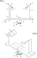
Figure 1 is a side elevation view of a joint according to a preferred embodiment of the present invention, - ▪
Figures 2 and3 are a top and bottom axonometric views of the joint inFig. 1 , - ▪
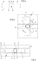
Figure 4 is a bottom plan view of the joint inFig. 1 , - ▪
Figure 5 illustrates a side elevation of a detail of the engagement seat for the joint ofFig. 1 made on a covering element such as to a slat and/or panel and/or slab according to the invention, - ▪
Figures 6 and 7 are top plan views of two fastening phases of the of the joint ofFig. 1 with a respective covering element, and - ▪
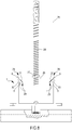
Fig. 8 is a side elevation view of the elements ofFigures 1 to 7 assembled on a support frame of a ceiling and/or wall covering system according to the present invention. - The following detailed description of the preferred embodiment must not be considered as a limitation to the scope of the invention and it refers to
Figures 1 to 8 , wherein terms such as horizontal and/or vertical, lateral, lower or upper specifically refer to them and to the position of the elements depicted therein. In practice, the elements of the preferred embodiment may be mounted to the ceiling and/or wall as necessary. - With reference to the annexed figures, in particular
figures 1-3 , with 1 it has been overall indicated a support joint according to a preferred embodiment of the present invention. As illustrated and reproduced in the figures, it can be seen that the joint 1 has an essentially Y-shaped section, comprising acentral base portion 2 from which protrude laterally two cantilever structural reinforcingelements 3, in correspondence to the joiningarea 4 between thecentral base portion 2 and the twocantilever elements 3, twoarms 5 extend upwards defining a first part of the Y-shaped section of the joint according to the invention. The two cantilever structural reinforcingelements 3, according to a preferred embodiment of the invention, are shaped and ribbed to ensure on the one hand the correct elasticity of thearms 5 and on the other hand the correct bending strength of thecentral base portion 2, when saidarms 5 are pulled apart in the assembly steps as described in more detail below. Each of the twoarms 5 is provided with a free end overall indicated in 6 having a substantially triangular cross-section, the triangular cross-section of the free end of thearms 5 defining a triangular tooth overall indicated in 7 facing inwards and towards the center of the joint according to the invention. More in detail, thetriangular section tooth 7 defines aninclined wall 8 and ahorizontal abutment surface 9. Thecentral base portion 2 is provided in correspondence to its centerline with a reinforcing thickenedportion 10 placed inside the upper arms of the Y-shaped section, while outside the Y-shaped section in correspondence to the reinforcing thickenedportion 10, and therefore also to the centerline of thebase portion 2, there is provided asupport pin 11 having a cross-shaped section and provided at its free end, indicated overall in 12, with a protruding shaped interlocking head indicated in 13. Thepin 11 and itshead 13 therefore define the lower leg of the Y-shaped section. - The protruding interlocking head has a major dimension defined by two
long sides 14 having a curvilinear shape, arranged substantially perpendicularly with respect to the length of thecentral base portion 2 and flush with the cross-section of thesupport pin 11, and a minor dimension defined by a pair ofshort sides 15 arranged substantially parallel with respect to the length of thebase portion 2. The pair of short sides also have a substantially curvilinear shape and are protruding with respect to the cross-section of thesupport pin 11, said protrusion however is contained within the width of thebase portion 2. In other words, the pair ofshort portions 15 in addition to protruding with respect to the cross section of thesupport pin 11 are of a width equal to or less than the width of thebase portion 2 of thejoint 1. -
Figure 5 schematically depicts a portion of a coveringelement 16 for ceilings and/or walls, saidelement 16 as easily understood by the average expert, may be a portion of a slat and/or a panel and/or a sheet or slab suitable for the purpose. - The covering
element 16 is defined by anon-visible face 18 and avisible face 19. - In order to implement the system according to the invention and to correctly perform the assembly of a covering
element 16 with a joint 1, as illustrated infigures 6 and 7 , the joint 1 must provide, if not present, a rail or track-like milling 20 along the entire length of the major dimension of the coveringelement 16 on itsnon-visible face 18. The person skilled in the art will have no difficulty in recognizing the most suitable and appropriate means of performing the track-like milling 20, where this is not present on the covering elements. - The track-
like milling 20, in a position equidistant from the edges of the coveringelement 16, is in turn composed of a lower zone havingrectangular cross-section 21 joined to anupper mouth zone 22, also having a rectangular cross-section but with an area smaller than the area of thelower zone 21, more precisely in order to define a sliding track. The smaller cross-section of theupper mouth area 22 is determined bylongitudinal edges 23, which contribute to confer the track-like milling 20 a shape suitable to accommodate the shaped protruding interlocking head overall indicated in 13. The width of the track-like milling 20 in itsupper mouth area 22 will be, with due tolerances, approximately equal to the interaxis between thelong sides 14 of thehead 13, the depth of the track milling 20 will be equal to the sum of the height of thepin 11 and the height of thehead 13. - In a preferred form of construction and by way of example, the sum of the height of the pin with the height of the joint head is less than the overall thickness of the covering element, so that the pin is only partially accommodated within the track-like seat of the covering element; preferably the pin height is between 7 and 14 mm, while the track-like seat can be between 5 and 10 mm deep.
- Furthermore, the width of the track-
like seat 20 is approximately equal to or greater than the largest dimension of the interlockinghead 13, preferably the width of the track-like seat 20 will be 15 mm or greater. - According to what will be illustrated even more in detail below, together with the assembly methods, the engagement between one or more interlocking heads 13 of
joints 1 and the rail milling 20 enables the coveringelements 16 to be stably fastened according to the invention with one or more interlocking heads 13 and thus with one ormore joints 1 according to the weight, dimensions and structural requirements of the coveringelements 16. - In order to correctly perform the assembly between the joint 1 and the covering
element 16, the joint 1 should be placed perpendicular to thenon-visible face 18 of the coveringelement 16 joint 1, such that thelong portions 14 of thehead 13 projecting from thepin 11 are aligned and parallel to the track-like milling 20. Given the dimensional relationships described above between the track-like milling 20,pin 11 andhead 13, with the joint positioned perpendicular to the track-like milling 20 of the coveringelement 16, thehead 13 will butt against the bottom of thelower area 21 of the milling. By turning the joint 1 by 90°, as shown for example infigure 6 , theshort sides 15 of thehead 13 which protrude from thepin 11 and which, by virtue of the dimensional relationships between the track-like milling 20,pin 11 andhead 13, are positioned below theupper mouth area 22 will lock in the position shown infigure 7 . - It will be clear to the person skilled in the art that this first step of partial assembly of a covering system according to the present invention may be carried out downstream in proximity to the final installation, then the fastening between the supporting framework on both ceiling and wall may be carried out and finalized.
- The assembly comprising, by way of example, a covering
element 16 and a joint 1, as described above and illustrated infigures 1 to 7 , is then ready to be fixed to a support frame shown infigure 8 . - In normal ceiling or wall coverings, threaded
metal elements 24 and generic elements and/or fastening means are provided in a known manner, these elements are conventionally attached and fixed to a ceiling and/or a wall schematically indicated by 25. On the threadedmetal element 25, it can be attached a conventional support frame element indicated byreference 26.Support frame 26 has generally an open C-shaped section, the correct positioning and fixing of the conventionalsupport frame element 26 is also achieved in a conventional manner, and by way of pure example by means of at least one adjustingnut 27 which is tightened against the conventionalsupport frame element 26. Longitudinally, bothsides 28 of the supportingwarping element 26 define twoslots 29, which therefore run along, or close to, the free ends of the section C of the supportingframe element 26. - The
longitudinal seats 29 are designed to house thetriangular section tooth 7 provided at the free end of thearms 5 of thejoint 1. In particular, theinclined wall 8 and thehorizontal abutment surface 9 will engage respectively on thecorresponding walls seats 29. - Given the elastic nature of the material(s) constituting the joint 1, this will be elastically engaged in the
seat 29 in such a way that thesurfaces arms 2 of the joint 1 are abutting and are retained by the correspondingwalls seats 29. - Advantageously, joint 1 is made from materials that allow elastic deformation, in particular, according to a preferred form of construction, joint 1 is made by molding polyethylene.
- Other plastic and/or metal materials with similar mechanical elasticity characteristics are also not excluded.
- Advantageously, the joint 1 may be elastically snapped to any conventional supporting
frame element 26 having a section of a suitable size to be housed between thearms 5 extending from thebase portion 2 of thejoint 1. It is also understood from the description and the drawings that the proportions between the conventional supporting frame elements and the fastening joint can vary while maintaining the proportions suitable for housing the support frame between thearms 2 of the joint, in such a way that the respective engagement surfaces 31 and 30 (for the supporting frame element) and 8 and 9 (of the joint arms) can engage in abutment ensuring a solid retention of the elastic interlocking elements snapped in their respective seats. It is in this manner achieved the scope of the invention by realizing auniversal joint 1 for many and various common commercial profiles used with the support frame of coverings for ceiling and/or wall. - Advantageously, the joint according to the invention allows for the realization of a system in which, after fixing the framework to the ceiling or wall, the covering elements are fastened by a simple snap-fit operation performed without intervening with complex assembly operations between the non-visible face of the covering elements and the framework fixed in place.
- Further advantages are obtained by the present invention due to the possibility of sliding of the covering elements with respect to the frame. In fact, since they are mounted by means of joints according to the invention, they are able to slide with respect to the housing seats of the frame, in order to compensate for any dimensional variations.
- The relative mobility of the covering elements makes it possible to carry out maintenance work on installations, such as electrical and/or computer network installations and ducts, lighting systems, etc., which may be located between the covering elements and the supporting frame, or between the supporting elements and the ceiling or wall on which the frame is installed.
- Further advantages may be found in the ease with which the covering elements can be removed from the supporting frame due to the presence of the joint according to the invention, which allows them to be just as easily detached from their supporting seats without the need for complicated disassembly operations.
Claims (13)
- Support joint (1) for coverings of ceilings and/or walls (25) of the type suitable to be fixed on one side thereof to at least one support framework element (26) and on the other side adapted to be engaged with and stably support a covering element (16) provided with at least one respective engagement seat (20), characterized in that said joint (1) has a central base portion (2) from which, on one side, a pair of shaped arms (5) is extended, such arms being spaced from each other and integral with said central base portion (2); from the opposite side of said base portion (2), at the center line thereof and equidistant from said pair of arms (5) being provided a support pin (11) having an interlocking head (13) adapted to be engaged with and to stably support said covering element (16) by means of said engagement seat (20).
- Support joint (1) for coverings of ceilings and/or walls according to claim 1, characterized in that from the central base portion (2), two cantilever elements laterally projected and in that the shaped arms (5) are extended in correspondence of the joining area (4) between the central base portion (2) and the two cantilever elements (3).
- Support joint (1) for coverings of ceilings and/or walls according to claim 1, characterized in that the shaped arms (5) are provided with a free end (6) having a substantially triangular section, defining a triangular tooth (7) directed towards the interior and towards the center of the Y-shaped section of the joint (1).
- Support joint (1) for coverings of ceilings and/or walls according to claim 1, characterized in that said central base portion (2), said pair of arms (5), said pin (11) and said interlocking head (13) define a substantially Y-shaped section for the joint.
- Support joint (1) for coverings of ceilings and/or walls according to claims 1-3, characterized in that said triangular tooth (7) defines a tilted wall (8) and a horizontal abutment surface (9) adapted to be stably engaged with a support framework element (26).
- Support joint (1) for coverings of ceilings and/or walls according to claim 1, characterized in that said covering element is provided with a track-like engagement seat (20) whose width, in the upper mouth zone (22) thereof, is substantially equal to the smaller dimension of said interlocking head (13), and whose depth is substantially equal to the sum of the heights of the pin (11) and of the interlocking head (13).
- Support joint (1) for coverings of ceilings and/or walls according to claim 1, characterized in that it is made by molding elastic polyethylene material.
- Support joint (1) for coverings of ceilings and/or walls according to claim 1, characterized in that it is made by molding of elastic metallic material.
- Support joint (1) for coverings of ceilings and/or walls according to one or more of the preceding claims, characterized in that the joint (1) has a Y-shaped section, within which it houses, with elastic snap-lock, a support framework element (26) with section and dimensions smaller than and/or equal to the center distance between said arms (5) which are extended from the base portion (2) of the joint (1).
- Support joint (1) for coverings of ceilings and/or walls according to claim 1, characterized in that said pin (11) has a cross-like section and that said shaped interlocking head (13) projects from said cross-like section of said pin (11) at its sides with smaller dimension.
- Support joint (1) for coverings of ceilings and/or walls according to claim 1, characterized in that a reinforcement element (10) is provided on said base portion (2) at the center line thereof and in correspondence to the side from which the arms (5) are extended.
- System for coverings of ceilings and/or walls constituted by and comprising:• one or more support framework elements (26) having an open C-shaped section, whose free ends longitudinally define engagement seats (29),• a plurality of covering elements (16) provided on the non-visible face of a track-like engagement seat (20),• a plurality of elastic support joints (1) engageable on one side with said one or more support framework elements (26) and on the other side with the track-like engagement seat (20) of said covering elements (16),• said one or more framework elements (26) supporting said plurality of joints (1) via elastic snap-lock,• said plurality of covering elements (16) being supported, by means of the face not visible from said plurality of joints (1), in a manner such that said covering elements (16) are arranged perpendicular with respect to said support framework elements (26), and are spaced therefrom by means of the support joints (1) interposed therebetween.
- Method for making coverings of ceilings and/or walls comprising the steps of:• making a framework of support elements with open C-shaped section having longitudinal fixing seats in proximity to the free ends thereof, said framework being stably fixed to a ceiling or to a wall,• arranging a plurality of covering elements and making, on the non-visible face thereof, a track-like engagement seat,• connecting said plurality of covering elements with joints provided on one side with support pin and interlocking head stably housable in said track-like seat, and on the other side with elastic arms engageable with said framework of support elements stably fixed to ceiling or to wall,• connecting said plurality of covering elements, previously assembled to the joints, by engaging the arms of the joints with the longitudinal fixing seats, provided in proximity to the free ends of the C-shaped section of the framework of the support elements, by only acting on the visible face of the covering elements.
Applications Claiming Priority (1)
| Application Number | Priority Date | Filing Date | Title |
|---|---|---|---|
| IT102020000014488A IT202000014488A1 (en) | 2020-06-17 | 2020-06-17 | SUPPORT JOINT FOR UNIVERSAL CLADDING OF CEILINGS AND/OR WALLS, CLADDING SYSTEM AND METHOD FOR REALIZING THE CLADDING SYSTEM |
Publications (1)
| Publication Number | Publication Date |
|---|---|
| EP3926119A1 true EP3926119A1 (en) | 2021-12-22 |
Family
ID=72356360
Family Applications (1)
| Application Number | Title | Priority Date | Filing Date |
|---|---|---|---|
| EP21175092.2A Withdrawn EP3926119A1 (en) | 2020-06-17 | 2021-05-20 | Support joint for universal coverings of ceilings and/or walls, covering system and method for making the covering system |
Country Status (2)
| Country | Link |
|---|---|
| EP (1) | EP3926119A1 (en) |
| IT (1) | IT202000014488A1 (en) |
Citations (3)
| Publication number | Priority date | Publication date | Assignee | Title |
|---|---|---|---|---|
| DE202007002282U1 (en) * | 2007-02-16 | 2008-06-19 | Möller GmbH & Co. KG | profile elements |
| US20170044773A1 (en) * | 2015-08-12 | 2017-02-16 | Michael Gernhart | Acoustic Leveling Clip |
| WO2017042521A1 (en) * | 2015-09-11 | 2017-03-16 | Stiplastics | Device for keeping a facing element at a spacing from a vapor barrier membrane, and dual-reinforcement construction system including such a device |
-
2020
- 2020-06-17 IT IT102020000014488A patent/IT202000014488A1/en unknown
-
2021
- 2021-05-20 EP EP21175092.2A patent/EP3926119A1/en not_active Withdrawn
Patent Citations (3)
| Publication number | Priority date | Publication date | Assignee | Title |
|---|---|---|---|---|
| DE202007002282U1 (en) * | 2007-02-16 | 2008-06-19 | Möller GmbH & Co. KG | profile elements |
| US20170044773A1 (en) * | 2015-08-12 | 2017-02-16 | Michael Gernhart | Acoustic Leveling Clip |
| WO2017042521A1 (en) * | 2015-09-11 | 2017-03-16 | Stiplastics | Device for keeping a facing element at a spacing from a vapor barrier membrane, and dual-reinforcement construction system including such a device |
Also Published As
| Publication number | Publication date |
|---|---|
| IT202000014488A1 (en) | 2021-12-17 |
Similar Documents
| Publication | Publication Date | Title |
|---|---|---|
| US6792727B2 (en) | Curved wall panel system | |
| US7966778B2 (en) | Device for the earthquake-resistant mounting of a partition | |
| US7640701B2 (en) | Deflection clip | |
| US20070209306A1 (en) | Fire rated wall structure | |
| US20100199594A1 (en) | Mounting clip | |
| EP1757751A1 (en) | Wall face exterior structure of outer wall face insulation building and its wall face exterior furring, lateral furring strip frame for installing wall face exterior material and wall face exterior froming method by lateral furring strip frame, and exterior furring material and outer wall employing | |
| CA3121820A1 (en) | Support bracket apparatus | |
| US20160273217A1 (en) | Ceiling system | |
| US9322167B2 (en) | Decking or flooring system, and components therefor | |
| US7832171B2 (en) | Construction framing system and track therefor | |
| US7578106B2 (en) | Wall molding for suspended ceiling | |
| CN114341445B (en) | Outer plate arrangement structure | |
| KR101463222B1 (en) | Structural panel assembly | |
| EP3926119A1 (en) | Support joint for universal coverings of ceilings and/or walls, covering system and method for making the covering system | |
| US20120144774A1 (en) | Fire rated wall structure | |
| US9103108B2 (en) | Drywall backing connector for steel studs | |
| US10253498B2 (en) | Building component | |
| RU2307906C2 (en) | Method for vented building face assemblage and enveloping structure for method realization | |
| DK202001195A1 (en) | Fire retarding and acoustic cladding system and method for arranging a fire retarding and acoustic cladding system | |
| KR101293688B1 (en) | Beam for exterior material of building | |
| JP6832637B2 (en) | Reinforcement method and structure of metal floor panel using anti-deflection metal fittings and anti-deflection metal fittings | |
| JP2023042259A (en) | Joint width adjustment metal fitting, and construction method of hanging wall structure | |
| JPH083562Y2 (en) | Mounting device for decorative wallboard | |
| AU2012100877B4 (en) | Decking or flooring system, and components therefor | |
| CN114687498A (en) | Fabricated ceiling cascade structure and mounting method thereof |
Legal Events
| Date | Code | Title | Description |
|---|---|---|---|
| PUAI | Public reference made under article 153(3) epc to a published international application that has entered the european phase |
Free format text: ORIGINAL CODE: 0009012 |
|
| STAA | Information on the status of an ep patent application or granted ep patent |
Free format text: STATUS: THE APPLICATION HAS BEEN PUBLISHED |
|
| AK | Designated contracting states |
Kind code of ref document: A1 Designated state(s): AL AT BE BG CH CY CZ DE DK EE ES FI FR GB GR HR HU IE IS IT LI LT LU LV MC MK MT NL NO PL PT RO RS SE SI SK SM TR |
|
| B565 | Issuance of search results under rule 164(2) epc |
Effective date: 20211110 |
|
| RIN1 | Information on inventor provided before grant (corrected) |
Inventor name: GALBIATI, VALERIA Inventor name: GIOLI, TOMMASO |
|
| STAA | Information on the status of an ep patent application or granted ep patent |
Free format text: STATUS: THE APPLICATION IS DEEMED TO BE WITHDRAWN |
|
| 18D | Application deemed to be withdrawn |
Effective date: 20220623 |