EP3926077A1 - Sliding member - Google Patents
Sliding member Download PDFInfo
- Publication number
- EP3926077A1 EP3926077A1 EP19915145.7A EP19915145A EP3926077A1 EP 3926077 A1 EP3926077 A1 EP 3926077A1 EP 19915145 A EP19915145 A EP 19915145A EP 3926077 A1 EP3926077 A1 EP 3926077A1
- Authority
- EP
- European Patent Office
- Prior art keywords
- intermediate layer
- overlay
- sliding member
- lining
- good
- Prior art date
- Legal status (The legal status is an assumption and is not a legal conclusion. Google has not performed a legal analysis and makes no representation as to the accuracy of the status listed.)
- Pending
Links
Images


Classifications
-
- F—MECHANICAL ENGINEERING; LIGHTING; HEATING; WEAPONS; BLASTING
- F16—ENGINEERING ELEMENTS AND UNITS; GENERAL MEASURES FOR PRODUCING AND MAINTAINING EFFECTIVE FUNCTIONING OF MACHINES OR INSTALLATIONS; THERMAL INSULATION IN GENERAL
- F16C—SHAFTS; FLEXIBLE SHAFTS; ELEMENTS OR CRANKSHAFT MECHANISMS; ROTARY BODIES OTHER THAN GEARING ELEMENTS; BEARINGS
- F16C33/00—Parts of bearings; Special methods for making bearings or parts thereof
- F16C33/02—Parts of sliding-contact bearings
- F16C33/04—Brasses; Bushes; Linings
- F16C33/06—Sliding surface mainly made of metal
- F16C33/12—Structural composition; Use of special materials or surface treatments, e.g. for rust-proofing
-
- F—MECHANICAL ENGINEERING; LIGHTING; HEATING; WEAPONS; BLASTING
- F16—ENGINEERING ELEMENTS AND UNITS; GENERAL MEASURES FOR PRODUCING AND MAINTAINING EFFECTIVE FUNCTIONING OF MACHINES OR INSTALLATIONS; THERMAL INSULATION IN GENERAL
- F16C—SHAFTS; FLEXIBLE SHAFTS; ELEMENTS OR CRANKSHAFT MECHANISMS; ROTARY BODIES OTHER THAN GEARING ELEMENTS; BEARINGS
- F16C33/00—Parts of bearings; Special methods for making bearings or parts thereof
- F16C33/02—Parts of sliding-contact bearings
- F16C33/04—Brasses; Bushes; Linings
- F16C33/06—Sliding surface mainly made of metal
- F16C33/12—Structural composition; Use of special materials or surface treatments, e.g. for rust-proofing
- F16C33/122—Multilayer structures of sleeves, washers or liners
- F16C33/124—Details of overlays
-
- B—PERFORMING OPERATIONS; TRANSPORTING
- B32—LAYERED PRODUCTS
- B32B—LAYERED PRODUCTS, i.e. PRODUCTS BUILT-UP OF STRATA OF FLAT OR NON-FLAT, e.g. CELLULAR OR HONEYCOMB, FORM
- B32B15/00—Layered products comprising a layer of metal
- B32B15/01—Layered products comprising a layer of metal all layers being exclusively metallic
- B32B15/017—Layered products comprising a layer of metal all layers being exclusively metallic one layer being formed of aluminium or an aluminium alloy, another layer being formed of an alloy based on a non ferrous metal other than aluminium
-
- C—CHEMISTRY; METALLURGY
- C25—ELECTROLYTIC OR ELECTROPHORETIC PROCESSES; APPARATUS THEREFOR
- C25D—PROCESSES FOR THE ELECTROLYTIC OR ELECTROPHORETIC PRODUCTION OF COATINGS; ELECTROFORMING; APPARATUS THEREFOR
- C25D5/00—Electroplating characterised by the process; Pretreatment or after-treatment of workpieces
- C25D5/10—Electroplating with more than one layer of the same or of different metals
-
- C—CHEMISTRY; METALLURGY
- C25—ELECTROLYTIC OR ELECTROPHORETIC PROCESSES; APPARATUS THEREFOR
- C25D—PROCESSES FOR THE ELECTROLYTIC OR ELECTROPHORETIC PRODUCTION OF COATINGS; ELECTROFORMING; APPARATUS THEREFOR
- C25D7/00—Electroplating characterised by the article coated
- C25D7/10—Bearings
-
- F—MECHANICAL ENGINEERING; LIGHTING; HEATING; WEAPONS; BLASTING
- F16—ENGINEERING ELEMENTS AND UNITS; GENERAL MEASURES FOR PRODUCING AND MAINTAINING EFFECTIVE FUNCTIONING OF MACHINES OR INSTALLATIONS; THERMAL INSULATION IN GENERAL
- F16C—SHAFTS; FLEXIBLE SHAFTS; ELEMENTS OR CRANKSHAFT MECHANISMS; ROTARY BODIES OTHER THAN GEARING ELEMENTS; BEARINGS
- F16C33/00—Parts of bearings; Special methods for making bearings or parts thereof
- F16C33/02—Parts of sliding-contact bearings
- F16C33/04—Brasses; Bushes; Linings
- F16C33/06—Sliding surface mainly made of metal
- F16C33/12—Structural composition; Use of special materials or surface treatments, e.g. for rust-proofing
- F16C33/121—Use of special materials
-
- F—MECHANICAL ENGINEERING; LIGHTING; HEATING; WEAPONS; BLASTING
- F16—ENGINEERING ELEMENTS AND UNITS; GENERAL MEASURES FOR PRODUCING AND MAINTAINING EFFECTIVE FUNCTIONING OF MACHINES OR INSTALLATIONS; THERMAL INSULATION IN GENERAL
- F16C—SHAFTS; FLEXIBLE SHAFTS; ELEMENTS OR CRANKSHAFT MECHANISMS; ROTARY BODIES OTHER THAN GEARING ELEMENTS; BEARINGS
- F16C33/00—Parts of bearings; Special methods for making bearings or parts thereof
- F16C33/02—Parts of sliding-contact bearings
- F16C33/04—Brasses; Bushes; Linings
- F16C33/06—Sliding surface mainly made of metal
- F16C33/12—Structural composition; Use of special materials or surface treatments, e.g. for rust-proofing
- F16C33/122—Multilayer structures of sleeves, washers or liners
-
- F—MECHANICAL ENGINEERING; LIGHTING; HEATING; WEAPONS; BLASTING
- F16—ENGINEERING ELEMENTS AND UNITS; GENERAL MEASURES FOR PRODUCING AND MAINTAINING EFFECTIVE FUNCTIONING OF MACHINES OR INSTALLATIONS; THERMAL INSULATION IN GENERAL
- F16C—SHAFTS; FLEXIBLE SHAFTS; ELEMENTS OR CRANKSHAFT MECHANISMS; ROTARY BODIES OTHER THAN GEARING ELEMENTS; BEARINGS
- F16C33/00—Parts of bearings; Special methods for making bearings or parts thereof
- F16C33/02—Parts of sliding-contact bearings
- F16C33/04—Brasses; Bushes; Linings
- F16C33/06—Sliding surface mainly made of metal
- F16C33/12—Structural composition; Use of special materials or surface treatments, e.g. for rust-proofing
- F16C33/122—Multilayer structures of sleeves, washers or liners
- F16C33/125—Details of bearing layers, i.e. the lining
-
- F—MECHANICAL ENGINEERING; LIGHTING; HEATING; WEAPONS; BLASTING
- F16—ENGINEERING ELEMENTS AND UNITS; GENERAL MEASURES FOR PRODUCING AND MAINTAINING EFFECTIVE FUNCTIONING OF MACHINES OR INSTALLATIONS; THERMAL INSULATION IN GENERAL
- F16C—SHAFTS; FLEXIBLE SHAFTS; ELEMENTS OR CRANKSHAFT MECHANISMS; ROTARY BODIES OTHER THAN GEARING ELEMENTS; BEARINGS
- F16C33/00—Parts of bearings; Special methods for making bearings or parts thereof
- F16C33/02—Parts of sliding-contact bearings
- F16C33/04—Brasses; Bushes; Linings
- F16C33/06—Sliding surface mainly made of metal
- F16C33/12—Structural composition; Use of special materials or surface treatments, e.g. for rust-proofing
- F16C33/122—Multilayer structures of sleeves, washers or liners
- F16C33/127—Details of intermediate layers, e.g. nickel dams
-
- C—CHEMISTRY; METALLURGY
- C25—ELECTROLYTIC OR ELECTROPHORETIC PROCESSES; APPARATUS THEREFOR
- C25D—PROCESSES FOR THE ELECTROLYTIC OR ELECTROPHORETIC PRODUCTION OF COATINGS; ELECTROFORMING; APPARATUS THEREFOR
- C25D3/00—Electroplating: Baths therefor
- C25D3/02—Electroplating: Baths therefor from solutions
- C25D3/56—Electroplating: Baths therefor from solutions of alloys
-
- C—CHEMISTRY; METALLURGY
- C25—ELECTROLYTIC OR ELECTROPHORETIC PROCESSES; APPARATUS THEREFOR
- C25D—PROCESSES FOR THE ELECTROLYTIC OR ELECTROPHORETIC PRODUCTION OF COATINGS; ELECTROFORMING; APPARATUS THEREFOR
- C25D3/00—Electroplating: Baths therefor
- C25D3/02—Electroplating: Baths therefor from solutions
- C25D3/56—Electroplating: Baths therefor from solutions of alloys
- C25D3/60—Electroplating: Baths therefor from solutions of alloys containing more than 50% by weight of tin
-
- F—MECHANICAL ENGINEERING; LIGHTING; HEATING; WEAPONS; BLASTING
- F16—ENGINEERING ELEMENTS AND UNITS; GENERAL MEASURES FOR PRODUCING AND MAINTAINING EFFECTIVE FUNCTIONING OF MACHINES OR INSTALLATIONS; THERMAL INSULATION IN GENERAL
- F16C—SHAFTS; FLEXIBLE SHAFTS; ELEMENTS OR CRANKSHAFT MECHANISMS; ROTARY BODIES OTHER THAN GEARING ELEMENTS; BEARINGS
- F16C2204/00—Metallic materials; Alloys
- F16C2204/02—Noble metals
- F16C2204/04—Noble metals based on silver
-
- F—MECHANICAL ENGINEERING; LIGHTING; HEATING; WEAPONS; BLASTING
- F16—ENGINEERING ELEMENTS AND UNITS; GENERAL MEASURES FOR PRODUCING AND MAINTAINING EFFECTIVE FUNCTIONING OF MACHINES OR INSTALLATIONS; THERMAL INSULATION IN GENERAL
- F16C—SHAFTS; FLEXIBLE SHAFTS; ELEMENTS OR CRANKSHAFT MECHANISMS; ROTARY BODIES OTHER THAN GEARING ELEMENTS; BEARINGS
- F16C2204/00—Metallic materials; Alloys
- F16C2204/10—Alloys based on copper
-
- F—MECHANICAL ENGINEERING; LIGHTING; HEATING; WEAPONS; BLASTING
- F16—ENGINEERING ELEMENTS AND UNITS; GENERAL MEASURES FOR PRODUCING AND MAINTAINING EFFECTIVE FUNCTIONING OF MACHINES OR INSTALLATIONS; THERMAL INSULATION IN GENERAL
- F16C—SHAFTS; FLEXIBLE SHAFTS; ELEMENTS OR CRANKSHAFT MECHANISMS; ROTARY BODIES OTHER THAN GEARING ELEMENTS; BEARINGS
- F16C2204/00—Metallic materials; Alloys
- F16C2204/20—Alloys based on aluminium
-
- Y—GENERAL TAGGING OF NEW TECHNOLOGICAL DEVELOPMENTS; GENERAL TAGGING OF CROSS-SECTIONAL TECHNOLOGIES SPANNING OVER SEVERAL SECTIONS OF THE IPC; TECHNICAL SUBJECTS COVERED BY FORMER USPC CROSS-REFERENCE ART COLLECTIONS [XRACs] AND DIGESTS
- Y10—TECHNICAL SUBJECTS COVERED BY FORMER USPC
- Y10T—TECHNICAL SUBJECTS COVERED BY FORMER US CLASSIFICATION
- Y10T428/00—Stock material or miscellaneous articles
- Y10T428/12—All metal or with adjacent metals
- Y10T428/12493—Composite; i.e., plural, adjacent, spatially distinct metal components [e.g., layers, joint, etc.]
- Y10T428/12681—Ga-, In-, Tl- or Group VA metal-base component
-
- Y—GENERAL TAGGING OF NEW TECHNOLOGICAL DEVELOPMENTS; GENERAL TAGGING OF CROSS-SECTIONAL TECHNOLOGIES SPANNING OVER SEVERAL SECTIONS OF THE IPC; TECHNICAL SUBJECTS COVERED BY FORMER USPC CROSS-REFERENCE ART COLLECTIONS [XRACs] AND DIGESTS
- Y10—TECHNICAL SUBJECTS COVERED BY FORMER USPC
- Y10T—TECHNICAL SUBJECTS COVERED BY FORMER US CLASSIFICATION
- Y10T428/00—Stock material or miscellaneous articles
- Y10T428/12—All metal or with adjacent metals
- Y10T428/12493—Composite; i.e., plural, adjacent, spatially distinct metal components [e.g., layers, joint, etc.]
- Y10T428/12708—Sn-base component
- Y10T428/12715—Next to Group IB metal-base component
-
- Y—GENERAL TAGGING OF NEW TECHNOLOGICAL DEVELOPMENTS; GENERAL TAGGING OF CROSS-SECTIONAL TECHNOLOGIES SPANNING OVER SEVERAL SECTIONS OF THE IPC; TECHNICAL SUBJECTS COVERED BY FORMER USPC CROSS-REFERENCE ART COLLECTIONS [XRACs] AND DIGESTS
- Y10—TECHNICAL SUBJECTS COVERED BY FORMER USPC
- Y10T—TECHNICAL SUBJECTS COVERED BY FORMER US CLASSIFICATION
- Y10T428/00—Stock material or miscellaneous articles
- Y10T428/12—All metal or with adjacent metals
- Y10T428/12493—Composite; i.e., plural, adjacent, spatially distinct metal components [e.g., layers, joint, etc.]
- Y10T428/12736—Al-base component
- Y10T428/1275—Next to Group VIII or IB metal-base component
-
- Y—GENERAL TAGGING OF NEW TECHNOLOGICAL DEVELOPMENTS; GENERAL TAGGING OF CROSS-SECTIONAL TECHNOLOGIES SPANNING OVER SEVERAL SECTIONS OF THE IPC; TECHNICAL SUBJECTS COVERED BY FORMER USPC CROSS-REFERENCE ART COLLECTIONS [XRACs] AND DIGESTS
- Y10—TECHNICAL SUBJECTS COVERED BY FORMER USPC
- Y10T—TECHNICAL SUBJECTS COVERED BY FORMER US CLASSIFICATION
- Y10T428/00—Stock material or miscellaneous articles
- Y10T428/12—All metal or with adjacent metals
- Y10T428/12493—Composite; i.e., plural, adjacent, spatially distinct metal components [e.g., layers, joint, etc.]
- Y10T428/12771—Transition metal-base component
- Y10T428/12861—Group VIII or IB metal-base component
- Y10T428/12882—Cu-base component alternative to Ag-, Au-, or Ni-base component
Definitions
- the present invention relates to a sliding member including an overlay of an alloy plating film of Bi and Sb.
- a sliding member that includes an overlay including a coating layer of Bi and an intermediate layer of Ag (see Patent Literature 1).
- Patent Literature 1 the size of a crystal grain of Ag in the intermediate layer is adjusted to improve the interlayer adhesion in the overlay.
- the size of a crystal grain of Bi in the coating layer is adjusted to improve the interlayer adhesion and the fatigue resistance in the overlay.
- Patent Literature 1 Japanese Patent No. 3693256
- Patent Literature 1 there has been a problem that in the case that an Al alloy is formed into a bearing alloy layer, delamination occurs between the bearing alloy layer of the Al alloy and the intermediate layer of Ag. This is because the adhesion between the Al alloy and the Ag plating film is poor.
- the present invention has been made in view of the above-described problems, and an object of the present invention is to provide a technique capable of reducing the possibility of generation of a Cu-Sb compound in an overlay and the possibility of delamination between layers.
- the sliding member of the present invention includes: an overlay including an alloy plating film of Bi and Sb; a lining including an Al alloy; a first intermediate layer including Cu as a main component, and laminated on the lining; and a second intermediate layer including Ag as a main component, and connecting the first intermediate layer and the overlay.
- the overlay includes not only soft Bi but also hard Sb, and as a result, the hard Sb can improve the fatigue resistance and the wear resistance.
- Cu has a property of diffusing into Sb more easily than into Bi. If the average concentration of Sb in the overlay is increased (for example, 3% by mass or more), Cu diffused from the first intermediate layer into the overlay may reduce the fatigue resistance.
- the second intermediate layer including Ag which serves as a diffusion barrier of Cu
- the first intermediate layer including Cu as a main component between the second intermediate layer including Ag as a main component and the lining
- the first intermediate layer including Cu as a main component between the second intermediate layer including Ag as a main component and the lining including an Al alloy
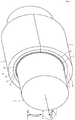
- Fig. 1 is a perspective view of sliding members 1 according to one embodiment of the present invention.
- the sliding member 1 includes a back metal 10, a lining 11, an intermediate layer 12, and an overlay 13.
- the sliding member 1 is a metal member having a halved cylindrical shape obtained by dividing a hollow cylinder into two equal parts in a diameter direction, and has a semicircular arc cross section. Two sliding members 1 are combined into a cylindrical shape to form a sliding bearing A.
- the sliding bearing A bears a cylindrical mating shaft 2 (crankshaft of an engine) in a hollow portion formed inside.
- the mating shaft 2 is formed to have an outer diameter slightly smaller than the inner diameter of the sliding bearing A.
- the gap formed between the outer peripheral surface of the mating shaft 2 and the inner peripheral surface of the sliding bearing A is supplied with a lubricating oil (engine oil). At that time, the outer peripheral surface of the mating shaft 2 slides on the inner peripheral surface of the sliding bearing A.
- a lubricating oil engine oil
- Fig. 2 is a schematic sectional view of the sliding member 1.
- the sliding member 1 has a structure in which the back metal 10, the lining 11, the intermediate layer 12, and the overlay 13 are stacked in this order from the side that is the farthest from the center of curvature. Therefore, the back metal 10 constitutes the outermost layer of the sliding member 1, and the overlay 13 constitutes the innermost layer of the sliding member 1.
- the back metal 10, the lining 11, the intermediate layer 12, and the overlay 13 each have a substantially constant thickness in the circumferential direction.
- the back metal 10 has a thickness of 1.8 mm
- the lining 11 has a thickness of 0.2 mm
- the intermediate layer 12 has a thickness of 6.0 ⁇ m
- the overlay 13 has a thickness of 15 ⁇ m.
- Twice the radius of a semicircle formed by the surface of the overlay 13 on the side closer to the center of curvature (the inner diameter of the sliding member 1) is 40 mm.
- the sliding bearing A has a width of 20 mm.
- the term “inner side” means the side closer to the center of curvature of the sliding member 1
- the term “outer side” means the side opposite from the center of curvature of the sliding member 1.
- the inner side surface of the overlay 13 constitutes a sliding surface for the mating shaft 2.
- the back metal 10 includes low-carbon steel containing 0.15% by mass of C, 0.06% by mass of Mn, and the rest including Fe.
- the back metal 10 is to include a material capable of supporting a load from the mating shaft 2 via the lining 11 and the overlay 13, and is not necessarily to include low-carbon steel.
- the lining 11 is a layer laminated on the inner side of the back metal 10.
- the lining 11 includes an Al alloy, and contains 7% by mass of Sn, 3% by mass of Si, and the rest including Al and an inevitable impurity.
- the inevitable impurity of the lining 11 is, for example, Mg, Ti, B, Pb, or Cr, and is mixed during refining or scrapping.
- the content of the inevitable impurity in the lining 11 is 0.5% by mass or less in total.
- the lining 11 is to include an Al alloy containing Al as a main component, and the composition of the Al alloy is not particularly limited.
- the intermediate layer 12 includes a first intermediate layer 12A and a second intermediate layer 12B.
- the first intermediate layer 12A includes Cu as a main component, and the first intermediate layer 12A is laminated on the lining 11.
- the second intermediate layer 12B includes Ag as a main component, and connects the first intermediate layer 12A and the overlay 13.
- the first intermediate layer 12A includes pure Ag
- the second intermediate layer 12B includes pure Cu.
- the content of the inevitable impurity in the intermediate layer 12 is 0.5% by mass or less in total.
- the first intermediate layer 12A has a thickness of 1 ⁇ m
- the second intermediate layer 12B has a thickness of 5 ⁇ m.
- the overlay 13 is a layer laminated on the inner side surface of the intermediate layer 12.
- the overlay 13 is an alloy plating film of Bi and Sb.
- the overlay 13 includes Bi, Sb, and an inevitable impurity.
- the overlay 13 includes Sb at a content of 5.5% by mass and the rest including Bi and the inevitable impurity.
- the concentration of Sb in the overlay 13 was measured with energy dispersive X-ray spectroscopy using an electron probe microanalyzer (JMS-6610A manufactured by JEOL Ltd.).
- the content of the inevitable impurity in the overlay 13 is 0.5% by mass or less in total.
- a fatigue test piece (connecting rod R) was prepared that was formed in the same manner as the sliding member 1 described above, and the fatigue area rate after the fatigue test was measured. As the result, the fatigue area rate was as good as 4%.
- the connecting rod R had an inner diameter of 40 mm and a width of 20 mm.
- FIG. 3 is an explanatory diagram of a sliding tester.
- a connecting rod R was prepared in which a cylindrical through hole was formed in each lengthwise end part, and a test shaft H (shown by hatching) was borne by the connecting rod R in the through hole at one end part.
- the connecting rod R bore the test shaft H in a state that the sliding member 1 (shown by black painting) was attached to the through hole.
- the test shaft H was borne at both outsides of the connecting rod R along the axis of the test shaft H, and was rotated so that the sliding speed was 7 m/sec.
- the sliding speed is a relative speed between the surface of the overlay 13 and the test shaft H.
- the end part of the connecting rod R on the opposite side from the test shaft H was connected to a moving body F that reciprocates in the length direction of the connecting rod R, and the reciprocating load of the moving body F was set to 90 MPa.
- an engine oil having a temperature of about 140°C was supplied between the sliding member 1 attached to the connecting rod R and the test shaft H.
- the above-described state was continued for 50 hours to perform the fatigue test of the overlay 13. Then, after the fatigue test, the inner side surface (sliding surface) of the overlay 13 was photographed from a position on a straight line orthogonal to the inner side surface so that the straight line was the main optical axis, and the photographed image was obtained as an evaluation image. Then, the damaged portion in the surface of the overlay 13 photographed in the evaluation image was observed with a binocular (magnifying glass) and identified, and the percentage value obtained by dividing the damaged portion area, the area of the damaged portion, by the area of the entire surface of the overlay 13 photographed in the evaluation image was measured as the fatigue area rate.
- a binocular magnifying glass
- a wear test piece (connecting rod R) was prepared that was formed in the same manner as the sliding member 1 of the present embodiment, and the wear amount after the wear test was measured. As the result, the wear amount was as good as 0.7 mm 3 .
- the wear test was also performed with the sliding tester shown in Fig. 3 . In the wear test, a state in which the sliding speed was kept at 3 m/s for 10 seconds and a state in which the sliding speed was kept at 0 m/s for 10 seconds were alternately repeated for 10 hours (1,800 cycles) continuously.
- the reciprocating load of the moving body F was set to 3 kPa.
- an engine oil having a temperature of about 100°C was supplied between the sliding member 1 attached to the connecting rod R and the test shaft H.
- the connecting rod R had an inner diameter of 50 mm and a width of 20 mm.
- the test pieces after the fatigue test and the wear test described above were observed to find that the plating adhesion between the lining 11, the first intermediate layer 12A, the second intermediate layer 12B, and the overlay 13 was good.
- the good plating adhesion means that delamination is not caused by the first intermediate layer 12A, the second intermediate layer 12B, and the overlay 13.
- the overlay 13 includes not only soft Bi but also hard Sb, and as a result, the hard Sb can improve the fatigue resistance and the wear resistance.
- Cu has a property of diffusing into Sb more easily than into Bi. If the average concentration of Sb in the overlay 13 is increased (for example, 3% by mass or more), Cu diffused from the first intermediate layer 12A into the overlay 13 may reduce the fatigue resistance.
- the second intermediate layer 12B including Ag which serves as a diffusion barrier of Cu, as a main component between the first intermediate layer 12A and the overlay 13, it is possible to reduce the amount of Cu diffused from the first intermediate layer 12A including Cu as a main component into the overlay 13 to reduce the possibility of deterioration in the fatigue resistance. Furthermore, by interposing the first intermediate layer 12A including Cu as a main component between the second intermediate layer 12B including Ag as a main component and the lining 11 including an Al alloy, it is possible to reduce the possibility of delamination between the second intermediate layer 12B and the lining 11.
- a molten material of a lining 11 was put into a mold, and the molten material of the lining 11 was drawn out from the opening of the mold in the casting direction to form a continuously cast sheet of the lining 11.
- the continuously cast sheet of the lining 11 was cold-rolled until the thickness of the continuously cast sheet reached the thickness of the lining 11.
- a low-carbon steel sheet (commercial product) of a back metal 10 was cold-rolled together to pressure-bond the low-carbon steel sheet of the back metal 10 to the Al alloy sheet side of an intermediate layer 12.
- a rolled sheet of a sliding member 1 was formed in which the continuously cast sheet of the lining 11 and the low-carbon steel sheet of the back metal 10 were pressure-bonded to each other.
- the predetermined size is a size in which the sliding member 1 can be formed through machining described below, and is a size determined by the shape of a connecting rod R to which the sliding member 1 is to be attached. Furthermore, the rolled sheet of the sliding member 1 after cutting was pressed to be formed into a halved cylindrical shape.
- Bi-Sb having a thickness of 15 ⁇ m was laminated on the surface of the second intermediate layer 12B through electroplating to form an overlay 13.
- the procedure of electroplating was as follows. First, the surface of the second intermediate layer 12B was washed with water. Furthermore, the surface of the second intermediate layer 12B was washed with an acid to remove an unnecessary oxide from the surface of the second intermediate layer 12B. Then, the surface of the second intermediate layer 12B was washed with water again.
- the lining 11 immersed in a plating bath was supplied with a current to perform electroplating.
- the bath composition of the plating bath included methanesulfonic acid: 150 g/L, a Bi ion: 30 g/L, a Sb ion: 1 g/L, and an organic surfactant: 25 g/L.
- the bath temperature of the plating bath was set to 30°C.
- the current supplied to the lining 11 was a direct current, and the current density was set to 3 A/dm 2 .
- the sliding member 1 was completed. Furthermore, two sliding members 1 were combined into a cylindrical shape to form a sliding bearing A, and the sliding bearing A was attached to an engine.
- Table 1 shows a comparison among the configurations in Examples 1 to 6 of the present invention and Comparative Examples 7 to 14.
- the test pieces in Examples 1 to 6 and Comparative Examples 7 to 14 are the sliding members 1 that are different in the content of Sb in the overlay 13, the thickness of the first intermediate layer 12A, or the thickness of the second intermediate layer 12B.
- Example 1 to 6 and Comparative Examples 7 to 14 the wear amount and the fatigue area rate were measured with the above-described methods.
- the first embodiment corresponds to Example 2.
- all of the wear resistance, the fatigue resistance, and the plating adhesion were good.
- any of the wear resistance, the fatigue resistance, and the plating adhesion were not good.
- the good wear resistance means that the wear amount is 1.0 mm 3 or less
- the good fatigue resistance means that the fatigue area rate is 10% or less.
- the plating adhesion was not good. This is because in Comparative Examples 13 and 14, the first intermediate layer 12A had a thickness of 0 ⁇ m and 0.1 ⁇ m respectively, and the thickness of the first intermediate layer 12A was insufficient. Meanwhile, in Example 6 in which the first intermediate layer 12A had a thickness of 0.3 ⁇ m, the plating adhesion was good. It has been confirmed that the plating adhesion is good in the case that the first intermediate layer 12A has a thickness of 0.3 ⁇ m or more.
- Table 2 shows the results of measuring the concentration of Cu diffused into the overlay 13 befor and after heat treatment.
- Example A a second intermediate layer 12B of pure Ag having a thickness of 2 ⁇ m was laminated on a Cu base.
- Example B a second intermediate layer 12B of Ag-Sn having a thickness of 2 ⁇ m was laminated on a Cu base.
- Comparative Example C a second intermediate layer 12B was omitted, and an overlay 13 was directly laminated on a Cu base.
- the content of Sn in the overlay 13 was set to 5% by mass. Furthermore, holding in the atmosphere at 150°C for 50 hours was performed as heat treatment.
- Example 4 in which the overlay 13 had a content of Sb of 10% by mass, both the wear resistance and the fatigue resistance were good. It has been confirmed that the quality of the plating film can be maintained in the overlay 13 having a content of Sb of 10% by mass or less, resulting in good wear resistance and good fatigue resistance.
- the sliding member 1 is exemplified that constitutes the sliding bearing A that bears a crankshaft of an engine, but the sliding member 1 of the present invention may be used for forming a sliding bearing A for another application.
- the sliding member 1 of the present invention may be used for forming a radial bearing such as a gear bush or a piston pin bush/boss bush for a transmission.
- the sliding member of the present invention may be a thrust bearing, various washers, or a swash plate for a car air conditioner compressor.
- the matrix of the lining 11 is not limited to a Cu alloy as long as the material of the matrix is selected according to the hardness of the mating shaft 2.
- the back metal 10 is not essential and may be omitted.
Landscapes
- Engineering & Computer Science (AREA)
- General Engineering & Computer Science (AREA)
- Chemical & Material Sciences (AREA)
- Mechanical Engineering (AREA)
- Chemical Kinetics & Catalysis (AREA)
- Electrochemistry (AREA)
- Materials Engineering (AREA)
- Metallurgy (AREA)
- Organic Chemistry (AREA)
- Sliding-Contact Bearings (AREA)
- Electroplating Methods And Accessories (AREA)
Abstract
Description
- The present invention relates to a sliding member including an overlay of an alloy plating film of Bi and Sb.
- A sliding member is known that includes an overlay including a coating layer of Bi and an intermediate layer of Ag (see Patent Literature 1). In
Patent Literature 1, the size of a crystal grain of Ag in the intermediate layer is adjusted to improve the interlayer adhesion in the overlay. Furthermore, the size of a crystal grain of Bi in the coating layer is adjusted to improve the interlayer adhesion and the fatigue resistance in the overlay. - Patent Literature 1:
Japanese Patent No. 3693256 - However, in
Patent Literature 1, there has been a problem that in the case that an Al alloy is formed into a bearing alloy layer, delamination occurs between the bearing alloy layer of the Al alloy and the intermediate layer of Ag. This is because the adhesion between the Al alloy and the Ag plating film is poor. - Furthermore, there has been a problem that use of a configuration in which Cu and Sb coexist in an overlay layer as in
Patent Literature 1 leads to formation of a Cu-Sb compound in the overlay layer, and the Cu-Sb compound causes deterioration of the fatigue resistance. - The present invention has been made in view of the above-described problems, and an object of the present invention is to provide a technique capable of reducing the possibility of generation of a Cu-Sb compound in an overlay and the possibility of delamination between layers.
- In order to achieve the above-described object, the sliding member of the present invention includes: an overlay including an alloy plating film of Bi and Sb; a lining including an Al alloy; a first intermediate layer including Cu as a main component, and laminated on the lining; and a second intermediate layer including Ag as a main component, and connecting the first intermediate layer and the overlay.
- In the above-described configuration, the overlay includes not only soft Bi but also hard Sb, and as a result, the hard Sb can improve the fatigue resistance and the wear resistance. Here, Cu has a property of diffusing into Sb more easily than into Bi. If the average concentration of Sb in the overlay is increased (for example, 3% by mass or more), Cu diffused from the first intermediate layer into the overlay may reduce the fatigue resistance.
- Meanwhile, by interposing the second intermediate layer including Ag, which serves as a diffusion barrier of Cu, as a main component between the first intermediate layer and the overlay, it is possible to reduce the amount of Cu diffused from the first intermediate layer including Cu as a main component into the overlay to reduce the possibility of deterioration in the fatigue resistance. Furthermore, by interposing the first intermediate layer including Cu as a main component between the second intermediate layer including Ag as a main component and the lining including an Al alloy, it is possible to reduce the possibility of delamination between the second intermediate layer and the lining.
-
-
Fig. 1 is a perspective view of sliding members according to an embodiment of the present invention. -
Fig. 2 is a schematic sectional view of a sliding member. -
FIG. 3 is an explanatory diagram of a fatigue test. - Here, embodiments of the present invention will be described in the following order.
- (1) First embodiment:
- (1-1) Configuration of sliding member:
- (1-2) Method for manufacturing sliding member:
- (2) Experimental results:
- (3) Other embodiments:
-
Fig. 1 is a perspective view of slidingmembers 1 according to one embodiment of the present invention. The slidingmember 1 includes aback metal 10, alining 11, anintermediate layer 12, and anoverlay 13. The slidingmember 1 is a metal member having a halved cylindrical shape obtained by dividing a hollow cylinder into two equal parts in a diameter direction, and has a semicircular arc cross section. Two slidingmembers 1 are combined into a cylindrical shape to form a sliding bearing A. The sliding bearing A bears a cylindrical mating shaft 2 (crankshaft of an engine) in a hollow portion formed inside. Themating shaft 2 is formed to have an outer diameter slightly smaller than the inner diameter of the sliding bearing A. The gap formed between the outer peripheral surface of themating shaft 2 and the inner peripheral surface of the sliding bearing A is supplied with a lubricating oil (engine oil). At that time, the outer peripheral surface of themating shaft 2 slides on the inner peripheral surface of the sliding bearing A. -
Fig. 2 is a schematic sectional view of the slidingmember 1. The slidingmember 1 has a structure in which theback metal 10, thelining 11, theintermediate layer 12, and theoverlay 13 are stacked in this order from the side that is the farthest from the center of curvature. Therefore, theback metal 10 constitutes the outermost layer of the slidingmember 1, and theoverlay 13 constitutes the innermost layer of the slidingmember 1. Theback metal 10, thelining 11, theintermediate layer 12, and theoverlay 13 each have a substantially constant thickness in the circumferential direction. Theback metal 10 has a thickness of 1.8 mm, thelining 11 has a thickness of 0.2 mm, theintermediate layer 12 has a thickness of 6.0 µm, and theoverlay 13 has a thickness of 15 µm. Twice the radius of a semicircle formed by the surface of theoverlay 13 on the side closer to the center of curvature (the inner diameter of the sliding member 1) is 40 mm. The sliding bearing A has a width of 20 mm. Hereinafter, the term "inner side" means the side closer to the center of curvature of the slidingmember 1, and the term "outer side" means the side opposite from the center of curvature of thesliding member 1. The inner side surface of theoverlay 13 constitutes a sliding surface for themating shaft 2. - The
back metal 10 includes low-carbon steel containing 0.15% by mass of C, 0.06% by mass of Mn, and the rest including Fe. Theback metal 10 is to include a material capable of supporting a load from themating shaft 2 via thelining 11 and theoverlay 13, and is not necessarily to include low-carbon steel. - The
lining 11 is a layer laminated on the inner side of theback metal 10. Thelining 11 includes an Al alloy, and contains 7% by mass of Sn, 3% by mass of Si, and the rest including Al and an inevitable impurity. The inevitable impurity of thelining 11 is, for example, Mg, Ti, B, Pb, or Cr, and is mixed during refining or scrapping. The content of the inevitable impurity in thelining 11 is 0.5% by mass or less in total. Thelining 11 is to include an Al alloy containing Al as a main component, and the composition of the Al alloy is not particularly limited. - The
intermediate layer 12 includes a firstintermediate layer 12A and a secondintermediate layer 12B. The firstintermediate layer 12A includes Cu as a main component, and the firstintermediate layer 12A is laminated on thelining 11. The secondintermediate layer 12B includes Ag as a main component, and connects the firstintermediate layer 12A and theoverlay 13. In the present embodiment, the firstintermediate layer 12A includes pure Ag, and the secondintermediate layer 12B includes pure Cu. The content of the inevitable impurity in theintermediate layer 12 is 0.5% by mass or less in total. The firstintermediate layer 12A has a thickness of 1 µm, and the secondintermediate layer 12B has a thickness of 5 µm. - The
overlay 13 is a layer laminated on the inner side surface of theintermediate layer 12. Theoverlay 13 is an alloy plating film of Bi and Sb. Theoverlay 13 includes Bi, Sb, and an inevitable impurity. Theoverlay 13 includes Sb at a content of 5.5% by mass and the rest including Bi and the inevitable impurity. The concentration of Sb in theoverlay 13 was measured with energy dispersive X-ray spectroscopy using an electron probe microanalyzer (JMS-6610A manufactured by JEOL Ltd.). The content of the inevitable impurity in theoverlay 13 is 0.5% by mass or less in total. - A fatigue test piece (connecting rod R) was prepared that was formed in the same manner as the sliding
member 1 described above, and the fatigue area rate after the fatigue test was measured. As the result, the fatigue area rate was as good as 4%. The connecting rod R had an inner diameter of 40 mm and a width of 20 mm. - The fatigue area rate was measured with the following procedure.
Fig. 3 is an explanatory diagram of a sliding tester. First, as shown inFig. 3 , a connecting rod R was prepared in which a cylindrical through hole was formed in each lengthwise end part, and a test shaft H (shown by hatching) was borne by the connecting rod R in the through hole at one end part. - Note that the connecting rod R bore the test shaft H in a state that the sliding member 1 (shown by black painting) was attached to the through hole. The test shaft H was borne at both outsides of the connecting rod R along the axis of the test shaft H, and was rotated so that the sliding speed was 7 m/sec. The sliding speed is a relative speed between the surface of the
overlay 13 and the test shaft H. The end part of the connecting rod R on the opposite side from the test shaft H was connected to a moving body F that reciprocates in the length direction of the connecting rod R, and the reciprocating load of the moving body F was set to 90 MPa. Furthermore, an engine oil having a temperature of about 140°C was supplied between the slidingmember 1 attached to the connecting rod R and the test shaft H. - The above-described state was continued for 50 hours to perform the fatigue test of the
overlay 13. Then, after the fatigue test, the inner side surface (sliding surface) of theoverlay 13 was photographed from a position on a straight line orthogonal to the inner side surface so that the straight line was the main optical axis, and the photographed image was obtained as an evaluation image. Then, the damaged portion in the surface of theoverlay 13 photographed in the evaluation image was observed with a binocular (magnifying glass) and identified, and the percentage value obtained by dividing the damaged portion area, the area of the damaged portion, by the area of the entire surface of theoverlay 13 photographed in the evaluation image was measured as the fatigue area rate. - Furthermore, a wear test piece (connecting rod R) was prepared that was formed in the same manner as the sliding
member 1 of the present embodiment, and the wear amount after the wear test was measured. As the result, the wear amount was as good as 0.7 mm3. The wear test was also performed with the sliding tester shown inFig. 3 . In the wear test, a state in which the sliding speed was kept at 3 m/s for 10 seconds and a state in which the sliding speed was kept at 0 m/s for 10 seconds were alternately repeated for 10 hours (1,800 cycles) continuously. The reciprocating load of the moving body F was set to 3 kPa. Furthermore, an engine oil having a temperature of about 100°C was supplied between the slidingmember 1 attached to the connecting rod R and the test shaft H. The connecting rod R had an inner diameter of 50 mm and a width of 20 mm. - The test pieces after the fatigue test and the wear test described above were observed to find that the plating adhesion between the lining 11, the first
intermediate layer 12A, the secondintermediate layer 12B, and theoverlay 13 was good. The good plating adhesion means that delamination is not caused by the firstintermediate layer 12A, the secondintermediate layer 12B, and theoverlay 13. - In the above-described embodiment, the
overlay 13 includes not only soft Bi but also hard Sb, and as a result, the hard Sb can improve the fatigue resistance and the wear resistance. Here, Cu has a property of diffusing into Sb more easily than into Bi. If the average concentration of Sb in theoverlay 13 is increased (for example, 3% by mass or more), Cu diffused from the firstintermediate layer 12A into theoverlay 13 may reduce the fatigue resistance. - Meanwhile, by interposing the second
intermediate layer 12B including Ag, which serves as a diffusion barrier of Cu, as a main component between the firstintermediate layer 12A and theoverlay 13, it is possible to reduce the amount of Cu diffused from the firstintermediate layer 12A including Cu as a main component into theoverlay 13 to reduce the possibility of deterioration in the fatigue resistance. Furthermore, by interposing the firstintermediate layer 12A including Cu as a main component between the secondintermediate layer 12B including Ag as a main component and the lining 11 including an Al alloy, it is possible to reduce the possibility of delamination between the secondintermediate layer 12B and thelining 11. - First, a molten material of a
lining 11 was put into a mold, and the molten material of thelining 11 was drawn out from the opening of the mold in the casting direction to form a continuously cast sheet of thelining 11. Next, the continuously cast sheet of thelining 11 was cold-rolled until the thickness of the continuously cast sheet reached the thickness of thelining 11. Furthermore, a low-carbon steel sheet (commercial product) of aback metal 10 was cold-rolled together to pressure-bond the low-carbon steel sheet of theback metal 10 to the Al alloy sheet side of anintermediate layer 12. As described above, a rolled sheet of a slidingmember 1 was formed in which the continuously cast sheet of thelining 11 and the low-carbon steel sheet of theback metal 10 were pressure-bonded to each other. - Next, the rolled sheet of the sliding
member 1 was cut into a predetermined size. The predetermined size is a size in which the slidingmember 1 can be formed through machining described below, and is a size determined by the shape of a connecting rod R to which the slidingmember 1 is to be attached. Furthermore, the rolled sheet of the slidingmember 1 after cutting was pressed to be formed into a halved cylindrical shape. - Next, Cu having a thickness of 1 µm was laminated on the surface of the lining 11 through electroplating to form a first
intermediate layer 12A. Next, Ag having a thickness of 5 µm was laminated on the surface of the firstintermediate layer 12A through electroplating to form a secondintermediate layer 12B. - Next, Bi-Sb having a thickness of 15 µm was laminated on the surface of the second
intermediate layer 12B through electroplating to form anoverlay 13. The procedure of electroplating was as follows. First, the surface of the secondintermediate layer 12B was washed with water. Furthermore, the surface of the secondintermediate layer 12B was washed with an acid to remove an unnecessary oxide from the surface of the secondintermediate layer 12B. Then, the surface of the secondintermediate layer 12B was washed with water again. - After completion of the above-described pretreatment, the lining 11 immersed in a plating bath was supplied with a current to perform electroplating. The bath composition of the plating bath included methanesulfonic acid: 150 g/L, a Bi ion: 30 g/L, a Sb ion: 1 g/L, and an organic surfactant: 25 g/L. The bath temperature of the plating bath was set to 30°C. Furthermore, the current supplied to the
lining 11 was a direct current, and the current density was set to 3 A/dm2. - After the above-described electroplating, water washing and drying were performed. Thus, the sliding
member 1 was completed. Furthermore, two slidingmembers 1 were combined into a cylindrical shape to form a sliding bearing A, and the sliding bearing A was attached to an engine. -
[Table 1] Overlay Thickness of first intermediate layer (Cu) [µm] Thickness of second intermediate layer (Ag) [µm] Wear amount [mm3] Fatigue area rate [%] Plating adhesion Content of Bi Content of Sb [% by mass] Example 1 Rest 3.0 1.0 5.0 0.9 7.0 Good Example 2 Rest 5.5 1.0 5.0 0.7 4.0 Good Example 3 Rest 7.2 1.0 5.0 0.6 2.0 Good Example 4 Rest 10.0 1.0 5.0 0.4 8.0 Good Example 5 Rest 5.5 1.0 3.0 0.7 4.0 Good Example 6 Rest 5.5 0.3 5.0 0.7 4.0 Good Comparative Example 7 Rest 0.0 1.0 5.0 2.4 38.0 Good Comparative Example 8 Rest 2.1 1.0 5.0 1.5 16.0 Good Comparative Example 9 Rest 8.5 1.0 0.0 0.5 14.0 Good Comparative Example 10 Rest 11.5 1.0 5.0 0.3 12.0 Good Comparative Example 11 Rest 13.7 1.0 5.0 0.2 24.0 Good Comparative Example 12 Rest 7.2 1.0 1.0 0.6 15.0 Good Comparative Example 13 Rest 8.5 0.0 5.0 - - Not good Comparative Example 14 Rest 8.5 0.1 5.0 - - Not good - Table 1 shows a comparison among the configurations in Examples 1 to 6 of the present invention and Comparative Examples 7 to 14. The test pieces in Examples 1 to 6 and Comparative Examples 7 to 14 are the sliding
members 1 that are different in the content of Sb in theoverlay 13, the thickness of the firstintermediate layer 12A, or the thickness of the secondintermediate layer 12B. - In Examples 1 to 6 and Comparative Examples 7 to 14, the wear amount and the fatigue area rate were measured with the above-described methods. The first embodiment corresponds to Example 2. In Examples 1 to 6, all of the wear resistance, the fatigue resistance, and the plating adhesion were good. In Comparative Examples 1 to 6, any of the wear resistance, the fatigue resistance, and the plating adhesion were not good. Note that the good wear resistance means that the wear amount is 1.0 mm3 or less, and the good fatigue resistance means that the fatigue area rate is 10% or less.
- As shown in Table 1, in Comparative Examples 13 and 14, the plating adhesion was not good. This is because in Comparative Examples 13 and 14, the first
intermediate layer 12A had a thickness of 0 µm and 0.1 µm respectively, and the thickness of the firstintermediate layer 12A was insufficient. Meanwhile, in Example 6 in which the firstintermediate layer 12A had a thickness of 0.3 µm, the plating adhesion was good. It has been confirmed that the plating adhesion is good in the case that the firstintermediate layer 12A has a thickness of 0.3 µm or more. - In Comparative Examples 9 and 12, the fatigue resistance was not good. This is because in Comparative Examples 9 and 12, the second
intermediate layer 12B had a thickness of 0 µm and 1 µm respectively, and the thickness of the secondintermediate layer 12B was insufficient. Meanwhile, in Example 5 in which the secondintermediate layer 12B had a thickness of 3 µm, the fatigue resistance was good.[Table 2] Second intermediate layer Time of measurement Concentration of Cu [% by mass] Measurement point (distance from Cu base in overlay) 1µm 2µm 4µm 6µm 9µm 14µm Example A Pure Ag (2 µm) Before heat treatment 0 0 0 0 0 0 After heat treatment 0 0 0 0 0 0 Example B Ag-Sn (2 µm) Before heat treatment 0 0 0 0 0 0 After heat treatment 0 0 0 0 0 0 Example C None Before heat treatment 0 0 0 0 0 0 After heat treatment 14.8 6.2 2.2 0.9 0.6 0.3 - Table 2 shows the results of measuring the concentration of Cu diffused into the
overlay 13 befor and after heat treatment. In Example A, a secondintermediate layer 12B of pure Ag having a thickness of 2 µm was laminated on a Cu base. In Example B, a secondintermediate layer 12B of Ag-Sn having a thickness of 2 µm was laminated on a Cu base. In Comparative Example C, a secondintermediate layer 12B was omitted, and anoverlay 13 was directly laminated on a Cu base. In Examples A and B and Comparative Example C, the content of Sn in theoverlay 13 was set to 5% by mass. Furthermore, holding in the atmosphere at 150°C for 50 hours was performed as heat treatment. - As shown in Table 2, in Comparative Example C in which the
overlay 13 was directly laminated on the Cu base, the measurement point that is less distant from the lower interface of theoverlay 13 has a larger concentration of Cu after the heat treatment. This is because Cu diffused from the base into theoverlay 13 in the heat treatment. Meanwhile, as in Examples A and B, it has been confirmed that the secondintermediate layer 12B including pure Ag or Ag-Sn having a thickness of 2 µm or more can sufficiently exhibit an effect of preventing diffusion of Cu into theoverlay 13. - In Comparative Examples 7 and 8 in Table 1, neither the wear resistance nor the fatigue resistance was good. This is because, in Comparative Examples 7 and 8, the
overlay 13 had a content of Sb of 0% by mass and 2.1% by mass respectively, and the content of hard Sb was insufficient. Meanwhile, in Example 1 in which theoverlay 13 had a content of Sb of 3% by mass, both the wear resistance and the fatigue resistance were good. It has been confirmed that theoverlay 13 having a content of Sb of 3% by mass or more can be strengthened, resulting in good wear resistance and good fatigue resistance. - Furthermore, in Comparative Examples 10 and 11, the fatigue resistance was not good. This is because the
overlay 13 had a content of Sb of 11.5% by mass and 13.7% by mass respectively, and the quality of the plating film of theoverlay 13 deteriorated due to excessive Sb. Meanwhile, in Example 4 in which theoverlay 13 had a content of Sb of 10% by mass, both the wear resistance and the fatigue resistance were good. It has been confirmed that the quality of the plating film can be maintained in theoverlay 13 having a content of Sb of 10% by mass or less, resulting in good wear resistance and good fatigue resistance. - In the above-described embodiment, the sliding
member 1 is exemplified that constitutes the sliding bearing A that bears a crankshaft of an engine, but the slidingmember 1 of the present invention may be used for forming a sliding bearing A for another application. For example, the slidingmember 1 of the present invention may be used for forming a radial bearing such as a gear bush or a piston pin bush/boss bush for a transmission. Furthermore, the sliding member of the present invention may be a thrust bearing, various washers, or a swash plate for a car air conditioner compressor. The matrix of the lining 11 is not limited to a Cu alloy as long as the material of the matrix is selected according to the hardness of themating shaft 2. Theback metal 10 is not essential and may be omitted. -
- 1
- Sliding member
- 2
- Mating shaft
- 10
- Back metal
- 11
- Lining
- 12
- Intermediate layer
- 12A
- First intermediate layer
- 12B
- Second intermediate layer
- 13
- Overlay
- A
- Sliding bearing
- F
- Moving body
- H
- Test shaft
- R
- Connecting rod
Claims (2)
- A sliding member comprising:an overlay including an alloy plating film of Bi and Sb;a lining including an Al alloy;a first intermediate layer including Cu as a main component, and laminated on the lining; anda second intermediate layer including Ag as a main component, and connecting the first intermediate layer and the overlay.
- The sliding member according to claim 1, wherein
the second intermediate layer includes pure Ag or Ag-Sn.
Applications Claiming Priority (2)
| Application Number | Priority Date | Filing Date | Title |
|---|---|---|---|
| JP2019025556A JP7195172B2 (en) | 2019-02-15 | 2019-02-15 | sliding member |
| PCT/JP2019/036772 WO2020166119A1 (en) | 2019-02-15 | 2019-09-19 | Sliding member |
Publications (2)
| Publication Number | Publication Date |
|---|---|
| EP3926077A1 true EP3926077A1 (en) | 2021-12-22 |
| EP3926077A4 EP3926077A4 (en) | 2022-11-23 |
Family
ID=72044606
Family Applications (1)
| Application Number | Title | Priority Date | Filing Date |
|---|---|---|---|
| EP19915145.7A Pending EP3926077A4 (en) | 2019-02-15 | 2019-09-19 | Sliding member |
Country Status (5)
| Country | Link |
|---|---|
| US (1) | US11959518B2 (en) |
| EP (1) | EP3926077A4 (en) |
| JP (1) | JP7195172B2 (en) |
| CN (1) | CN113302343B (en) |
| WO (1) | WO2020166119A1 (en) |
Families Citing this family (2)
| Publication number | Priority date | Publication date | Assignee | Title |
|---|---|---|---|---|
| CN115679319B (en) * | 2022-10-31 | 2025-04-11 | 河南起重机器有限公司 | A process for soft anti-friction coating by electric spark alloying on the surface of tin-bronze bearing |
| JP2024155308A (en) | 2023-04-21 | 2024-10-31 | 大同メタル工業株式会社 | Sliding member |
Family Cites Families (7)
| Publication number | Priority date | Publication date | Assignee | Title |
|---|---|---|---|---|
| JP3693256B2 (en) * | 2003-05-29 | 2005-09-07 | 大同メタル工業株式会社 | Sliding member |
| AT503735B1 (en) * | 2006-06-09 | 2008-05-15 | Miba Gleitlager Gmbh | COMPOSITE STOCK |
| JP5123240B2 (en) | 2009-03-24 | 2013-01-23 | 大同メタル工業株式会社 | Sliding member |
| JP4709294B2 (en) | 2009-04-15 | 2011-06-22 | 大同メタル工業株式会社 | Sliding member |
| AT509112B1 (en) | 2009-12-10 | 2011-09-15 | Miba Gleitlager Gmbh | SLIDING LAYER |
| AT509459B1 (en) * | 2010-04-15 | 2011-09-15 | Miba Gleitlager Gmbh | anti-fretting |
| WO2019017182A1 (en) * | 2017-07-21 | 2019-01-24 | 大豊工業株式会社 | Sliding member and sliding bearing |
-
2019
- 2019-02-15 JP JP2019025556A patent/JP7195172B2/en active Active
- 2019-09-19 EP EP19915145.7A patent/EP3926077A4/en active Pending
- 2019-09-19 US US17/422,316 patent/US11959518B2/en active Active
- 2019-09-19 WO PCT/JP2019/036772 patent/WO2020166119A1/en not_active Ceased
- 2019-09-19 CN CN201980089551.0A patent/CN113302343B/en active Active
Also Published As
| Publication number | Publication date |
|---|---|
| US11959518B2 (en) | 2024-04-16 |
| CN113302343B (en) | 2024-04-19 |
| JP7195172B2 (en) | 2022-12-23 |
| CN113302343A (en) | 2021-08-24 |
| US20220090631A1 (en) | 2022-03-24 |
| WO2020166119A1 (en) | 2020-08-20 |
| EP3926077A4 (en) | 2022-11-23 |
| JP2020132924A (en) | 2020-08-31 |
Similar Documents
| Publication | Publication Date | Title |
|---|---|---|
| EP2133580B1 (en) | Slide bearing | |
| US10982712B2 (en) | Sliding member | |
| US20210040988A1 (en) | Sliding member and sliding bearing | |
| EP3926077A1 (en) | Sliding member | |
| US11149791B2 (en) | Sliding member | |
| CN110582593B (en) | Sliding member | |
| JP6895338B2 (en) | Sliding members and plain bearings | |
| JPH07122158B2 (en) | Multilayer plain bearing with overlay | |
| EP3133306A1 (en) | Sliding member and sliding bearing | |
| US12209612B2 (en) | Sliding member | |
| JP6944019B2 (en) | Sliding members and plain bearings | |
| JP6762915B2 (en) | Sliding members and plain bearings |
Legal Events
| Date | Code | Title | Description |
|---|---|---|---|
| STAA | Information on the status of an ep patent application or granted ep patent |
Free format text: STATUS: THE INTERNATIONAL PUBLICATION HAS BEEN MADE |
|
| PUAI | Public reference made under article 153(3) epc to a published international application that has entered the european phase |
Free format text: ORIGINAL CODE: 0009012 |
|
| STAA | Information on the status of an ep patent application or granted ep patent |
Free format text: STATUS: REQUEST FOR EXAMINATION WAS MADE |
|
| 17P | Request for examination filed |
Effective date: 20210910 |
|
| AK | Designated contracting states |
Kind code of ref document: A1 Designated state(s): AL AT BE BG CH CY CZ DE DK EE ES FI FR GB GR HR HU IE IS IT LI LT LU LV MC MK MT NL NO PL PT RO RS SE SI SK SM TR |
|
| DAV | Request for validation of the european patent (deleted) | ||
| DAX | Request for extension of the european patent (deleted) | ||
| RIN1 | Information on inventor provided before grant (corrected) |
Inventor name: SUGA, SHIGEYUKI |
|
| A4 | Supplementary search report drawn up and despatched |
Effective date: 20221025 |
|
| RIC1 | Information provided on ipc code assigned before grant |
Ipc: C25D 3/60 20060101ALN20221019BHEP Ipc: C25D 3/56 20060101ALN20221019BHEP Ipc: F16C 33/12 20060101ALI20221019BHEP Ipc: C25D 5/10 20060101ALI20221019BHEP Ipc: C22C 12/00 20060101ALI20221019BHEP Ipc: C25D 7/10 20060101AFI20221019BHEP |
|
| STAA | Information on the status of an ep patent application or granted ep patent |
Free format text: STATUS: EXAMINATION IS IN PROGRESS |
|
| 17Q | First examination report despatched |
Effective date: 20230804 |