EP3925935A1 - Method of sintering glass preform with reduced helium consumption - Google Patents
Method of sintering glass preform with reduced helium consumption Download PDFInfo
- Publication number
- EP3925935A1 EP3925935A1 EP21171064.5A EP21171064A EP3925935A1 EP 3925935 A1 EP3925935 A1 EP 3925935A1 EP 21171064 A EP21171064 A EP 21171064A EP 3925935 A1 EP3925935 A1 EP 3925935A1
- Authority
- EP
- European Patent Office
- Prior art keywords
- glass preform
- present disclosure
- helium gas
- sintering
- time period
- Prior art date
- Legal status (The legal status is an assumption and is not a legal conclusion. Google has not performed a legal analysis and makes no representation as to the accuracy of the status listed.)
- Pending
Links
Images




Classifications
-
- C—CHEMISTRY; METALLURGY
- C03—GLASS; MINERAL OR SLAG WOOL
- C03B—MANUFACTURE, SHAPING, OR SUPPLEMENTARY PROCESSES
- C03B37/00—Manufacture or treatment of flakes, fibres, or filaments from softened glass, minerals, or slags
- C03B37/01—Manufacture of glass fibres or filaments
- C03B37/012—Manufacture of preforms for drawing fibres or filaments
- C03B37/014—Manufacture of preforms for drawing fibres or filaments made entirely or partially by chemical means, e.g. vapour phase deposition of bulk porous glass either by outside vapour deposition [OVD], or by outside vapour phase oxidation [OVPO] or by vapour axial deposition [VAD]
- C03B37/01446—Thermal after-treatment of preforms, e.g. dehydrating, consolidating, sintering
Definitions
- the present disclosure relates to the field of optical fibre and in particular, relates to a method of sintering glass preform with reduced helium consumption.
- optical fibre is a flexible, transparent fibre made by drawing glass (silica) or plastic to a diameter slightly thicker than that of a human hair.
- the glass optical fibre is made from glass "preform".
- This preform is sintered soot deposited on bait rod.
- the sintering of the soot preform produces a dense and non-porous glass preform.
- sintering of the preform is performed using high consumption of helium.
- high consumption of helium increases over all cost of the manufacturing process as helium is costlier than other inert gases like argon and nitrogen.
- helium consumption in sintering is 390 to 430 times volume of soot at existing level. Further, helium is non-renewable natural resource and is depleting with time. Furthermore, cost and supply of helium is controlled by foreign countries which makes us dependent.
- the present disclosure provides a method for sintering of a glass preform with reduced helium gas consumption.
- the method includes a first step to perform dehydration of the soot preform inside a dehydration module.
- the method includes a second step to perform down-feeding of the glass preform inside a sintering furnace.
- the method includes a third step to perform sintering of the glass preform inside the sintering furnace.
- the method includes a fourth step to move the glass preform in upward motion.
- the glass preform undergoes dehydration for time period in range of about 20 minutes to 120 minutes. Dehydration of the glass preform is performed in presence of chlorine gas or mixture of chlorine and other inert gases.
- down-feeding of the glass preform is done for about 10 minutes.
- sintering of the glass preform is done in one or more sintering stages.
- the one or more sintering stages include but may not be limited to first sintering stage, second sintering stage, and third sintering stage and so on.
- the glass preform undergoes upward motion for about 1 minute.
- the glass preform undergoes re-sintering for about 10 to 25 minutes.
- a primary object of the present disclosure is to provide a method for sintering of a glass preform with reduced helium gas consumption.
- Another object of the present disclosure is to provide the glass preform with reduced cost.
- Yet another object of the present disclosure is to provide the method to reduce helium gas consumption by 30 percent without affecting any optical or other parameter of the fiber obtained from glass preform processed in this way.
- the dehydration module is utilized to perform dehydration of the glass preform in presence of helium gas.
- the sintering furnace is utilized to perform sintering of the glass preform in presence of helium gas.
- rate of flow of helium gas during dehydration of the glass preform is about 5 to 40 standard liter per minute for time period in range of about 20 minutes to 120 minutes.
- the glass preform is kept inside the sintering furnace at temperature of about 1200° to 1400° Celsius for about 20 to 60 mins.
- the glass preform is moving in the sintering furnace for about 5 to 10 minutes.
- the glass preform undergoes first sintering stage for about 120 to 160 minutes.
- the glass preform is fed with helium gas during dehydration and sintering in semi-continuous way.
- the glass preform undergoes second sintering stage for about 100 to 150 minutes.
- the glass preform undergoes third sintering stage for about 80 to 100 minutes.
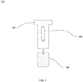
- FIG. 1 this is a general overview of a system 100 for sintering of a glass preform 102, in accordance with various embodiments of the present disclosure.
- the system 100 includes the glass preform 102, a dehydration module 104, and a sintering furnace 106.
- the system 100 includes the glass preform 102.
- glass preform is cylindrical body having core structure and cladding structure.
- glass preform is material used for fabrication of optical fibres.
- the glass preform 102 is manufactured using OVD process.
- OVD refers to outside vapor deposition.
- OTD outside vapor deposition
- glass preform is manufactured by depositing silica soot on surface of some target rod.
- the glass preform 102 is manufactured using VAD process.
- VAD process refers to as vapor axial deposition (VAD) process.
- vapor axial deposition process is used to manufacture porous glass preform.
- vapor axial deposition process facilitates fabrication of porous glass preform by depositing fine glass material onto end surface of starting material through flame hydrolysis. Furthermore, starting material is pulled upward in axial direction and porous glass preform is grown in the same direction.
- starting material is volatile organic compound that includes but may not be limited to SiCl 4 , GeCl 4 and O 2 .
- porous glass preform is heated to manufacture transparent fibre preform.
- the glass preform 102 is manufactured using ACVD process.
- ACVD process refers to atmospheric chemical vapor deposition process.
- the glass preform 102 is manufactured using PCVD process.
- PCVD process refers to plasma chemical vapor deposition process.
- the glass preform 102 is manufactured by depositing silica soot over glass body.
- silica soot is powdery or flaky substance consists largely of amorphous carbon and produced by incomplete burning of organic matter.
- glass body is mounted on lathe.
- lathe is machine tool that rotates glass body about axis of rotation to perform various operations. Further, various operations performed by lathe are cutting, drilling, knurling, deformation, and the like. Furthermore, glass body is placed on heat source and reacts with gases.
- the glass preform 102 is manufactured by depositing silica soot over glass body.
- silica soot deposited over glass body is densified above glass transition temperature.
- the glass preform 102 is manufactured in non-vacuum environment.
- non-vacuum environment consolidates silica soot over glass body in presence of inert gases with high thermal conductivity.
- inert gases include helium, argon and the like.
- inert gases are used for thermal diffusion inside porous soot surface.
- the system 100 includes the dehydration module 104.
- the dehydration module 104 is utilized to perform dehydration of the glass preform 102.
- dehydration corresponds to drying of glass preform.
- dehydration removes water and other impurities from glass preform.
- dehydration refers to removal of OH ion content from glass preform.
- dehydration of the glass preform 102 is performed inside the dehydration module 104 in presence of chlorine or mixture of chlorine and inert gas.
- dehydration of the glass preform 102 is performed inside the dehydration module 104 in presence of argon gas.
- dehydration of the glass preform 102 is performed inside the dehydration module 104 in presence of any suitable gaseous atmosphere.
- the system 100 includes the sintering furnace 106.
- the sintering furnace 106 is utilized to perform sintering of the glass preform 102. Further, sintering of the glass preform 102 causes shrinkage during glass transition temperature. Furthermore, sintering reduces porosity of the glass preform 102.
- the glass preform 102 undergoes down-feeding into the sintering furnace 106. In an embodiment of the present disclosure, the down-feeding of the glass preform 102 into the sintering furnace 106 is performed in presence of helium gas. The down-feeding of the glass preform 102 into the sintering furnace 106 facilitates sintering of the glass preform 102.
- the sintering furnace 106 receives helium gas at flow rate in range of about 20 standard litre per minute to 40 standard litre per minute during sintering of the glass preform 102. In another embodiment of the present disclosure, range of flow rate of helium gas in the sintering furnace 106 may vary. In another embodiment of the present disclosure, consumption of helium gas during sintering of the glass preform 102 may vary. In an embodiment of the present disclosure, flow of helium gas inside the sintering furnace 106 is done in semi-continuous way.
- the flow chart 200 initiates at step 202.
- dehydration of the glass preform 102 is performed inside the dehydration module 104.
- the glass preform 102 undergoes dehydration for time period in range of about 20 minutes to 120 minutes.
- time period for dehydration of the glass preform 102 may vary.
- rate of flow of helium gas during dehydration of the glass preform 102 is about 35 standard litre per minute for time period in range of about 20 minutes to 40 minutes.
- rate of flow of helium gas during dehydration of the glass preform 102 may vary.
- dehydration of the glass preform 102 is performed in presence of helium gas. In another embodiment of the present disclosure, dehydration of the glass preform 102 is performed in presence of any suitable inert gas.
- the glass preform 102 undergoes down-feeding into the sintering furnace 106.
- time taken by the glass preform 102 to reach the sintering furnace 106 is about 10 minutes.
- time taken by the glass preform 102 to reach the sintering furnace 106 may vary.
- the glass preform 102 undergoes down-feeding inside the sintering furnace 106.
- rate of flow of helium gas during down-feeding of the glass preform 102 is about 35 standard litre per minute. In another embodiment of the present disclosure, rate of flow of helium gas during down-feeding of the glass preform 102 may vary.
- the glass preform 102 is kept inside the sintering furnace 106 at temperature of about 1400° Celsius. In another embodiment of the present disclosure, temperature of the glass preform 102 inside sintering furnace 106 may vary. In an embodiment of the present disclosure, the glass preform 102 is kept at temperature 1400° Celsius for time period of about 40 minutes. In another embodiment of the present disclosure, time to maintain temperature of the glass preform 102 at 1400° Celsius may vary. In an embodiment of the present disclosure, the glass preform 102 is feed with helium gas at temperature 1400° Celsius. In an embodiment of the present disclosure, rate of flow of helium gas towards the glass preform 102 at temperature 1400° Celsius is about 25 to 40 standard liter per minute. In another embodiment of the present disclosure, rate of flow of helium gas towards the glass preform 102 may vary.
- the glass preform 102 is moving in the sintering furnace 106 for time period of about 5 to 10 minutes. In another embodiment of the present disclosure, time period to move the glass preform 102 in the sintering furnace 106 may vary. In an embodiment of the present disclosure, the glass preform 102 moves inside the sintering furnace 106 in presence of helium gas
- the glass preform 102 undergoes sintering inside the sintering furnace 106.
- sintering of the glass preform 102 is performed in one or more sintering stages.
- the one or more sintering stages include but may not be limited to first sintering stage, second sintering stage, and third sintering stage.
- the glass preform 102 undergoes first sintering stage.
- the glass preform 102 undergoes first sintering stage for time period of about 150 to 200 minutes.
- time period for sintering of the glass preform 102 at first sintering stage may vary.
- rate of flow of helium gas during first sintering stage is about 25 to 40 standard liter per minute. In another embodiment of the present disclosure, rate of flow of helium gas during first sintering stage may vary.
- the glass preform 102 undergoes second sintering stage. In an embodiment of the present disclosure, the glass preform 102 undergoes second sintering stage for time period of about 114.6 minutes. In another embodiment of the present disclosure, time period for sintering the glass preform 102 during second sintering stage for may vary. In an embodiment of the present disclosure, rate of flow of helium gas during second sintering stage is about 35 standard litre per minute. In another embodiment of the present disclosure, rate of flow of helium gas during second sintering stage may vary.
- the glass preform 102 undergoes third sintering stage. In an embodiment of the present disclosure, the glass preform 102 undergoes third sintering stage for time period of about 94.1 minutes. In another embodiment of the present disclosure, time period for sintering of the glass preform 102 during third sintering stage may vary. In an embodiment of the present disclosure, rate of flow of helium gas during third sintering stage is about 35 standard litre per minute. In another embodiment of the present disclosure, rate of flow of helium gas during third sintering stage may vary.
- the glass preform 102 undergoes upward motion after the one or more sintering stages.
- the glass preform 102 undergoes upward motion for time period of about 1 minute.
- time period for upward motion of the glass preform 102 may vary.
- the glass preform 102 is feed with helium gas during upward motion.
- rate of flow of helium during upward motion is about 35 standard litre per minute.
- rate of flow of helium gas during upward motion may vary.
- the glass preform 102 undergoes re-sintering.
- the glass preform 102 undergoes re-sintering for time period of about 22.7 minutes.
- time period for re-sintering of the glass preform 102 may vary.
- rate of flow of helium gas during re-sintering of the glass preform 102 is about 35 standard litre per minute.
- rate of flow of helium gas during re-sintering of the glass preform 102 may vary.
- the flow chart terminates at step 214.
- this is a graph 300 for flow pattern of helium gas consumption during dehydration and sintering of the glass preform 102, in accordance with an embodiment of the present disclosure.
- the graph 300 describes flow pattern of helium gas during dehydration and sintering of the glass preform 102.
- helium gas is introduced in continuous way.
- rate of flow of helium gas as shown in the graph 300 is about 25 standard litre per minute for any particular time. In another embodiment of the present disclosure, rate of flow of helium gas may vary for any particular time.
- this is a graph 400 for flow pattern of helium gas consumption during dehydration and sintering of the glass preform 102, in accordance with an embodiment of the present disclosure.
- the graph 400 describes flow pattern of helium gas during dehydration and sintering of the glass preform 102.
- helium gas is introduced in semi-continuous way.
- flow of helium gas for time in between 0 seconds to 55 seconds is 25 standard litre per minute.
- flow of helium gas is halt for time in between 55 seconds to 60 seconds as shown in the graph 400.
- flow of helium gas for time in between 60 seconds to 80 seconds is 25 standard litre per minute.
- helium gas consumption in semi-continuous way reduces overall consumption of helium gas during dehydration and sintering of the glass preform 102.
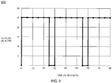
- this is a graph 500 for flow pattern of helium gas consumption during dehydration and sintering of the glass preform 102, in accordance with an embodiment of the present disclosure.
- the graph 500 describes flow pattern of helium gas during dehydration and sintering of the glass preform 102.
- helium gas is introduced in semi-continuous way.
- flow of helium gas for time in between 0 seconds to 25 seconds is 25 standard litre per minute.
- flow of helium gas is halt for time in between 25 seconds to 30 seconds as shown in the graph 400.
- helium gas is re-introduced with flow of about 25 standard litre per minute for time in between 30 seconds to 55 seconds. Furthermore, flow of helium gas is halt for time in between 55 seconds to 60 seconds. Moreover, helium gas is re-introduced for time in between 60 seconds to 80 seconds with flow of 25 standard litre per minute.
- this is a graph 600 for flow pattern of helium gas consumption during dehydration and sintering of the glass preform 102, in accordance with an embodiment of the present disclosure.
- the graph 600 describes flow pattern of helium gas during dehydration and sintering of the glass preform 102.
- helium gas is introduced in non-continuous way.
- flow of helium gas for time in between 0 seconds to 25 seconds is 25 standard litre per minute.
- flow of helium gas is reduced to 12.5 standard litre per minute for time in between 25 seconds to 30 seconds.
- helium gas is re-introduced with flow of about 25 standard litre per minute for time in between 30 seconds to 55 seconds. Furthermore, flow of helium gas is halt for time in between 55 seconds to 60 seconds. Moreover, helium gas is re-introduced for time in between 60 seconds to 80 seconds with flow of 25 standard litre per minute. In an embodiment of the present disclosure, helium gas consumption in non-continuous way reduces overall consumption of helium gas during dehydration and sintering of the glass preform 102.
- this is a graph 700 for flow pattern of helium gas consumption during dehydration and sintering of the glass preform 102, in accordance with an embodiment of the present disclosure.
- the graph 700 describes flow pattern of helium gas during dehydration and sintering of the glass preform 102.
- helium gas is introduced in non-continuous way.
- rate of flow of helium gas during dehydration and sintering of the glass preform 102 is defined by threshold value.
- threshold value for helium gas is 25 standard litre per minute.
- flow of helium gas for time in between 0 seconds to 5 seconds is 6.25 standard litre per minute.
- flow of helium gas for time in between 5 seconds to 10 seconds is 12.5 standard litre per minute. In an embodiment of the present disclosure, flow of helium gas for time in between 10 seconds to 15 seconds is 18.75 standard litre per minute. In an embodiment of the present disclosure, flow of helium gas for time in between 15 seconds to 20 seconds is 25 standard litre per minute.
- flow of helium gas for time in between 20 seconds to 25 seconds is 18.75 standard litre per minute. In an embodiment of the present disclosure, flow of helium gas for time in between 25 seconds to 30 seconds is 12.5 standard litre per minute. In an embodiment of the present disclosure, flow of helium gas for time in between 30 seconds to 35 seconds is 6.25 standard litre per minute. In an embodiment of the present disclosure, flow of helium gas for time in between 35 seconds to 40 seconds is 0 standard litre per minute.
- flow of helium gas for time in between 40 seconds to 45 seconds is 6.25 standard litre per minute. In an embodiment of the present disclosure, flow of helium gas for time in between 45 seconds to 50 seconds is 12.5 standard litre per minute. In an embodiment of the present disclosure, flow of helium gas for time in between 50 seconds to 55 seconds is 18.75 standard litre per minute. In an embodiment of the present disclosure, flow of helium gas for time in between 55 seconds to 60 seconds is 25 standard litre per minute.
- flow of helium gas for time in between 60 seconds to 65 seconds is 18.75 standard litre per minute. In an embodiment of the present disclosure, flow of helium gas for time in between 65 seconds to 70 seconds is 12.5 standard litre per minute. In an embodiment of the present disclosure, flow of helium gas for time in between 70 seconds to 75 seconds is 6.25 standard litre per minute. In an embodiment of the present disclosure, flow of helium gas for time in between 75 seconds to 80 seconds is 0 standard litre per minute.
- the graph 800 describes flow pattern of helium gas during dehydration and sintering of the glass preform 102.
- helium gas is introduced in non-continuous way.
- flow of helium gas for time in between 0 seconds to 5 seconds is 7 standard liter per minute.
- flow of helium gas for time in between 5 seconds to 10 seconds is 10 standard litre per minute.
- flow of helium gas for time in between 10 seconds to 15 seconds is 12 standard litre per minute.
- flow of helium gas for time in between 15 seconds to 20 seconds is 13 standard litre per minute.
- flow of helium gas for time in between 20 seconds to 25 seconds is 13 standard litre per minute. In an embodiment of the present disclosure, flow of helium gas for time in between 25 seconds to 30 seconds is 12 standard litre per minute. In an embodiment of the present disclosure, flow of helium gas for time in between 30 seconds to 35 seconds is 10 standard litre per minute. In an embodiment of the present disclosure, flow of helium gas for time in between 35 seconds to 40 seconds is 7 standard litre per minute. In an embodiment of the present disclosure, flow of helium gas for time in between 40 seconds to 45 seconds is 0 standard litre per minute.
- flow of helium gas for time in between 45 seconds to 50 seconds is 7 standard litre per minute. In an embodiment of the present disclosure, flow of helium gas for time in between 50 seconds to 55 seconds is 10 standard litre per minute. In an embodiment of the present disclosure, flow of helium gas for time in between 55 seconds to 60 seconds is 12 standard litre per minute. In an embodiment of the present disclosure, flow of helium gas for time in between 60 seconds to 65 seconds is 13 standard litre per minute.
- flow of helium gas for time in etween 65 seconds to 70 seconds is 13 standard litre per minute. In an embodiment of the present disclosure, flow of helium gas for time in between 70 seconds to 75 seconds is 12 standard litre per minute. In an embodiment of the present disclosure, flow of helium gas for time in between 75 seconds to 80 seconds is 10 standard litre per minute. In an embodiment of the present disclosure, flow of helium gas for time in between 80 seconds to 85 seconds is 7 standard litre per minute. In an embodiment of the present disclosure, flow of helium gas for time in between 85 seconds to 90 seconds is 0 standard litre per minute. In an embodiment of the present disclosure, helium gas consumption in non-continuous way reduces overall consumption of helium gas during dehydration and sintering of the glass preform 102.
- the present disclosure provides numerous advantages over the prior art.
- the present disclosure provides an improved method for sintering of the glass preform with reduced helium gas consumption.
- the method used to provide the glass preform with reduced cost Further, the method reduces helium gas consumption by 30 percent without affecting optical parameter of the glass preform.
Landscapes
- Chemical & Material Sciences (AREA)
- Engineering & Computer Science (AREA)
- Chemical Kinetics & Catalysis (AREA)
- Physics & Mathematics (AREA)
- General Chemical & Material Sciences (AREA)
- Life Sciences & Earth Sciences (AREA)
- Thermal Sciences (AREA)
- General Life Sciences & Earth Sciences (AREA)
- Geochemistry & Mineralogy (AREA)
- Manufacturing & Machinery (AREA)
- Materials Engineering (AREA)
- Organic Chemistry (AREA)
- Manufacture, Treatment Of Glass Fibers (AREA)
- Glass Compositions (AREA)
Abstract
Description
- The present disclosure relates to the field of optical fibre and in particular, relates to a method of sintering glass preform with reduced helium consumption.
- With the advancement of science and technology, various modern technologies are being employed for communication purposes. One of the most important modern communication technologies is optical fibre. In general, optical fibre is a flexible, transparent fibre made by drawing glass (silica) or plastic to a diameter slightly thicker than that of a human hair. The glass optical fibre is made from glass "preform". This preform is sintered soot deposited on bait rod. The sintering of the soot preform produces a dense and non-porous glass preform. Conventionally, sintering of the preform is performed using high consumption of helium. However, high consumption of helium increases over all cost of the manufacturing process as helium is costlier than other inert gases like argon and nitrogen. In addition, helium consumption in sintering is 390 to 430 times volume of soot at existing level. Further, helium is non-renewable natural resource and is depleting with time. Furthermore, cost and supply of helium is controlled by foreign countries which makes us dependent.
- In light of the above stated discussion, there is a need of an advanced method for sintering of a glass preform that overcomes the above stated drawbacks.
- In an aspect, the present disclosure provides a method for sintering of a glass preform with reduced helium gas consumption. The method includes a first step to perform dehydration of the soot preform inside a dehydration module. In addition, the method includes a second step to perform down-feeding of the glass preform inside a sintering furnace. Further, the method includes a third step to perform sintering of the glass preform inside the sintering furnace. Furthermore, the method includes a fourth step to move the glass preform in upward motion. Also, the glass preform undergoes dehydration for time period in range of about 20 minutes to 120 minutes. Dehydration of the glass preform is performed in presence of chlorine gas or mixture of chlorine and other inert gases. Also, down-feeding of the glass preform is done for about 10 minutes. Also, sintering of the glass preform is done in one or more sintering stages. The one or more sintering stages include but may not be limited to first sintering stage, second sintering stage, and third sintering stage and so on. Also, the glass preform undergoes upward motion for about 1 minute. Also, the glass preform undergoes re-sintering for about 10 to 25 minutes.
- A primary object of the present disclosure is to provide a method for sintering of a glass preform with reduced helium gas consumption.
- Another object of the present disclosure is to provide the glass preform with reduced cost.
- Yet another object of the present disclosure is to provide the method to reduce helium gas consumption by 30 percent without affecting any optical or other parameter of the fiber obtained from glass preform processed in this way.
- In an embodiment of the present disclosure, the dehydration module is utilized to perform dehydration of the glass preform in presence of helium gas.
- In an embodiment of the present disclosure, the sintering furnace is utilized to perform sintering of the glass preform in presence of helium gas.
- In an embodiment of the present disclosure, rate of flow of helium gas during dehydration of the glass preform is about 5 to 40 standard liter per minute for time period in range of about 20 minutes to 120 minutes.
- In an embodiment of the present disclosure, the glass preform is kept inside the sintering furnace at temperature of about 1200° to 1400° Celsius for about 20 to 60 mins.
- In an embodiment of the present disclosure, the glass preform is moving in the sintering furnace for about 5 to 10 minutes.
- In an embodiment of the present disclosure, the glass preform undergoes first sintering stage for about 120 to 160 minutes.
- In an embodiment of the present disclosure, the glass preform is fed with helium gas during dehydration and sintering in semi-continuous way.
- In an embodiment of the present disclosure, the glass preform undergoes second sintering stage for about 100 to 150 minutes.
- In an embodiment of the present disclosure, the glass preform undergoes third sintering stage for about 80 to 100 minutes.
- In order to best describe the manner in which the above-described embodiments are implemented, as well as define other advantages and features of the disclosure, a more particular description is provided below and is illustrated in the appended drawings. Understanding that these drawings depict only exemplary embodiments of the invention and are not therefore to be considered to be limiting in scope, the examples will be described and explained with additional specificity and detail through the use of the accompanying drawings in which:
-
FIG. 1 illustrates a general overview of a system for sintering of a glass preform, in accordance with various embodiments of the present disclosure; -
FIG. 2 illustrates a flowchart describing a method for sintering of the glass preform, in accordance with various embodiments of the present disclosure; -
FIG. 3 illustrates a graph for flow pattern of helium gas consumption during dehydration and sintering of the glass preform, in accordance with an embodiment of the present disclosure; -
FIG. 4 illustrates the graph for flow pattern of helium gas consumption during dehydration and sintering of the glass preform, in accordance with another embodiment of the present disclosure; -
FIG. 5 illustrates the graph for flow pattern of helium gas consumption during dehydration and sintering of the glass preform, in accordance with yet another embodiment of the present disclosure; -
FIG. 6 illustrates the graph for flow pattern of helium gas consumption during dehydration and sintering of the glass preform, in accordance with yet another embodiment of the present disclosure; -
FIG. 7 illustrates the graph for flow pattern of helium gas consumption during dehydration and sintering of the glass preform, in accordance with yet another embodiment of the present disclosure; and -
FIG. 8 illustrates the graph for flow pattern of helium gas consumption during dehydration and sintering of the glass preform, in accordance with yet another embodiment of the present disclosure. - It should be noted that the accompanying figures are intended to present illustrations of few exemplary embodiments of the present disclosure. These figures are not intended to limit the scope of the present disclosure. It should also be noted that accompanying figures are not necessarily drawn to scale.
- For a more complete understanding of the present invention parts, reference is now made to the following descriptions:
- 100.
- The system.
- 102.
- The glass preform.
- 104.
- The dehydration module.
- 106.
- The sintering furnace.
- 200.
- Flow chart.
- 202.
-
Step 202. - 204.
-
Step 204. - 206.
-
Step 206. - 208.
-
Step 208. - 210.
-
Step 210. - 212.
-
Step 212. - 214.
-
Step 214. - 300.
- Graph.
- 400.
- Graph.
- 500.
- Graph.
- 600.
- Graph.
- 700.
- Graph.
- 800.
- Graph.
- The following detailed description is of the best currently contemplated modes of carrying out exemplary embodiments of the invention. The description is not to be taken in a limiting sense, but is made merely for the purpose of illustrating the general principles of the invention.
- Reference in this specification to "one embodiment" or "an embodiment" means that a particular feature, structure, or characteristic described in connection with the embodiment is included in at least one embodiment of the present technology. The appearance of the phrase "in one embodiment" in various places in the specification are not necessarily all referring to the same embodiment, nor are separate or alternative embodiments mutually exclusive of other embodiments. Moreover, various features are described which may be exhibited by some embodiments and not by others. Similarly, various requirements are described which may be requirements for some embodiments but not other embodiments.
- Reference will now be made in detail to selected embodiments of the present disclosure in conjunction with accompanying figures. The embodiments described herein are not intended to limit the scope of the disclosure, and the present disclosure should not be construed as limited to the embodiments described. This disclosure may be embodied in different forms without departing from the scope and spirit of the disclosure. It should be understood that the accompanying figures are intended and provided to illustrate embodiments of the disclosure described below and are not necessarily drawn to scale. In the drawings, like numbers refer to like elements throughout, and thicknesses and dimensions of some components may be exaggerated for providing better clarity and ease of understanding.
- Moreover, although the following description contains many specifics for the purposes of illustration, anyone skilled in the art will appreciate that many variations and/or alterations to said details are within the scope of the present technology. Similarly, although many of the features of the present technology are described in terms of each other, or in conjunction with each other, one skilled in the art will appreciate that many of these features can be provided independently of other features. Accordingly, this description of the present technology is set forth without any loss of generality to, and without imposing limitations upon, the present technology.
- It should be noted that the terms "first", "second", and the like, herein do not denote any order, ranking, quantity, or importance, but rather are used to distinguish one element from another. Further, the terms "a" and "an" herein do not denote a limitation of quantity, but rather denote the presence of at least one of the referenced item.
- According to
FIG. 1 , this is a general overview of asystem 100 for sintering of aglass preform 102, in accordance with various embodiments of the present disclosure. Thesystem 100 includes theglass preform 102, adehydration module 104, and asintering furnace 106. - The
system 100 includes theglass preform 102. In general, glass preform is cylindrical body having core structure and cladding structure. In addition, glass preform is material used for fabrication of optical fibres. - In an embodiment of the present disclosure, the
glass preform 102 is manufactured using OVD process. In general, OVD refers to outside vapor deposition. In addition, outside vapor deposition (OVD) is process in which glass preform is manufactured by depositing silica soot on surface of some target rod. - In another embodiment of the present disclosure, the
glass preform 102 is manufactured using VAD process. In general, VAD process refers to as vapor axial deposition (VAD) process. In addition, vapor axial deposition process is used to manufacture porous glass preform. Further, vapor axial deposition process facilitates fabrication of porous glass preform by depositing fine glass material onto end surface of starting material through flame hydrolysis. Furthermore, starting material is pulled upward in axial direction and porous glass preform is grown in the same direction. Moreover, starting material is volatile organic compound that includes but may not be limited to SiCl4, GeCl4 and O2. Also, porous glass preform is heated to manufacture transparent fibre preform. - In yet another embodiment of the present disclosure, the
glass preform 102 is manufactured using ACVD process. In general, ACVD process refers to atmospheric chemical vapor deposition process. - In yet another embodiment of the present disclosure, the
glass preform 102 is manufactured using PCVD process. In general, PCVD process refers to plasma chemical vapor deposition process. - In an embodiment of the present disclosure, the
glass preform 102 is manufactured by depositing silica soot over glass body. In general, silica soot is powdery or flaky substance consists largely of amorphous carbon and produced by incomplete burning of organic matter. In an example, glass body is mounted on lathe. In addition, lathe is machine tool that rotates glass body about axis of rotation to perform various operations. Further, various operations performed by lathe are cutting, drilling, knurling, deformation, and the like. Furthermore, glass body is placed on heat source and reacts with gases. - In an example, the
glass preform 102 is manufactured by depositing silica soot over glass body. In addition, silica soot deposited over glass body is densified above glass transition temperature. In another example, theglass preform 102 is manufactured in non-vacuum environment. In addition, non-vacuum environment consolidates silica soot over glass body in presence of inert gases with high thermal conductivity. Further, inert gases include helium, argon and the like. Furthermore, inert gases are used for thermal diffusion inside porous soot surface. - The
system 100 includes thedehydration module 104. Thedehydration module 104 is utilized to perform dehydration of theglass preform 102. In general, dehydration corresponds to drying of glass preform. In addition, dehydration removes water and other impurities from glass preform. Further, dehydration refers to removal of OH ion content from glass preform. In an embodiment of the present disclosure, dehydration of theglass preform 102 is performed inside thedehydration module 104 in presence of chlorine or mixture of chlorine and inert gas. In another embodiment of the present disclosure, dehydration of theglass preform 102 is performed inside thedehydration module 104 in presence of argon gas. In yet another embodiment of the present disclosure, dehydration of theglass preform 102 is performed inside thedehydration module 104 in presence of any suitable gaseous atmosphere. - The
system 100 includes thesintering furnace 106. Thesintering furnace 106 is utilized to perform sintering of theglass preform 102. Further, sintering of theglass preform 102 causes shrinkage during glass transition temperature. Furthermore, sintering reduces porosity of theglass preform 102. In addition, theglass preform 102 undergoes down-feeding into thesintering furnace 106. In an embodiment of the present disclosure, the down-feeding of theglass preform 102 into thesintering furnace 106 is performed in presence of helium gas. The down-feeding of theglass preform 102 into thesintering furnace 106 facilitates sintering of theglass preform 102. In an embodiment of the present disclosure, thesintering furnace 106 receives helium gas at flow rate in range of about 20 standard litre per minute to 40 standard litre per minute during sintering of theglass preform 102. In another embodiment of the present disclosure, range of flow rate of helium gas in thesintering furnace 106 may vary. In another embodiment of the present disclosure, consumption of helium gas during sintering of theglass preform 102 may vary. In an embodiment of the present disclosure, flow of helium gas inside thesintering furnace 106 is done in semi-continuous way. - According to
FIG. 2 , this is aflow chart 200 describing steps to manufacture theglass preform 102, in accordance with various embodiments of the present disclosure. Theflow chart 200 initiates atstep 202. Followingstep 202, atstep 204, dehydration of theglass preform 102 is performed inside thedehydration module 104. In an embodiment of the present disclosure, theglass preform 102 undergoes dehydration for time period in range of about 20 minutes to 120 minutes. In another embodiment of the present disclosure, time period for dehydration of theglass preform 102 may vary. In an embodiment of the present disclosure, rate of flow of helium gas during dehydration of theglass preform 102 is about 35 standard litre per minute for time period in range of about 20 minutes to 40 minutes. In another embodiment of the present disclosure, rate of flow of helium gas during dehydration of theglass preform 102 may vary. - In an embodiment of the present disclosure, dehydration of the
glass preform 102 is performed in presence of helium gas. In another embodiment of the present disclosure, dehydration of theglass preform 102 is performed in presence of any suitable inert gas. - At
step 206, theglass preform 102 undergoes down-feeding into thesintering furnace 106. In an embodiment of the present disclosure, time taken by theglass preform 102 to reach thesintering furnace 106 is about 10 minutes. In another embodiment of the present disclosure, time taken by theglass preform 102 to reach thesintering furnace 106 may vary. In an embodiment of the present disclosure, theglass preform 102 undergoes down-feeding inside thesintering furnace 106. In an embodiment of the present disclosure, rate of flow of helium gas during down-feeding of theglass preform 102 is about 35 standard litre per minute. In another embodiment of the present disclosure, rate of flow of helium gas during down-feeding of theglass preform 102 may vary. - In an embodiment of the present disclosure, the
glass preform 102 is kept inside thesintering furnace 106 at temperature of about 1400° Celsius. In another embodiment of the present disclosure, temperature of theglass preform 102 insidesintering furnace 106 may vary. In an embodiment of the present disclosure, theglass preform 102 is kept at temperature 1400° Celsius for time period of about 40 minutes. In another embodiment of the present disclosure, time to maintain temperature of theglass preform 102 at 1400° Celsius may vary. In an embodiment of the present disclosure, theglass preform 102 is feed with helium gas at temperature 1400° Celsius. In an embodiment of the present disclosure, rate of flow of helium gas towards theglass preform 102 at temperature 1400° Celsius is about 25 to 40 standard liter per minute. In another embodiment of the present disclosure, rate of flow of helium gas towards theglass preform 102 may vary. - In an embodiment of the present disclosure, the
glass preform 102 is moving in thesintering furnace 106 for time period of about 5 to 10 minutes. In another embodiment of the present disclosure, time period to move theglass preform 102 in thesintering furnace 106 may vary. In an embodiment of the present disclosure, theglass preform 102 moves inside thesintering furnace 106 in presence of helium gas - At
step 208, theglass preform 102 undergoes sintering inside thesintering furnace 106. In an embodiment of the present disclosure, sintering of theglass preform 102 is performed in one or more sintering stages. In an embodiment of the present disclosure, the one or more sintering stages include but may not be limited to first sintering stage, second sintering stage, and third sintering stage. In an embodiment of the present disclosure, theglass preform 102 undergoes first sintering stage. In an embodiment of the present disclosure, theglass preform 102 undergoes first sintering stage for time period of about 150 to 200 minutes. In another embodiment of the present disclosure, time period for sintering of theglass preform 102 at first sintering stage may vary. In an embodiment of the present disclosure, rate of flow of helium gas during first sintering stage is about 25 to 40 standard liter per minute. In another embodiment of the present disclosure, rate of flow of helium gas during first sintering stage may vary. - In an embodiment of the present disclosure, the
glass preform 102 undergoes second sintering stage. In an embodiment of the present disclosure, theglass preform 102 undergoes second sintering stage for time period of about 114.6 minutes. In another embodiment of the present disclosure, time period for sintering theglass preform 102 during second sintering stage for may vary. In an embodiment of the present disclosure, rate of flow of helium gas during second sintering stage is about 35 standard litre per minute. In another embodiment of the present disclosure, rate of flow of helium gas during second sintering stage may vary. - In an embodiment of the present disclosure, the
glass preform 102 undergoes third sintering stage. In an embodiment of the present disclosure, theglass preform 102 undergoes third sintering stage for time period of about 94.1 minutes. In another embodiment of the present disclosure, time period for sintering of theglass preform 102 during third sintering stage may vary. In an embodiment of the present disclosure, rate of flow of helium gas during third sintering stage is about 35 standard litre per minute. In another embodiment of the present disclosure, rate of flow of helium gas during third sintering stage may vary. - At
step 210, theglass preform 102 undergoes upward motion after the one or more sintering stages. In an embodiment of the present disclosure, theglass preform 102 undergoes upward motion for time period of about 1 minute. In another embodiment of the present disclosure, time period for upward motion of theglass preform 102 may vary. In an embodiment of the present disclosure, theglass preform 102 is feed with helium gas during upward motion. In an embodiment of the present disclosure, rate of flow of helium during upward motion is about 35 standard litre per minute. In another embodiment of the present disclosure, rate of flow of helium gas during upward motion may vary. - At
step 212, theglass preform 102 undergoes re-sintering. In an embodiment of the present disclosure, theglass preform 102 undergoes re-sintering for time period of about 22.7 minutes. In another embodiment of the present disclosure, time period for re-sintering of theglass preform 102 may vary. In an embodiment of the present disclosure, rate of flow of helium gas during re-sintering of theglass preform 102 is about 35 standard litre per minute. In another embodiment of the present disclosure, rate of flow of helium gas during re-sintering of theglass preform 102 may vary. The flow chart terminates atstep 214. - According to
FIG. 3 , this is agraph 300 for flow pattern of helium gas consumption during dehydration and sintering of theglass preform 102, in accordance with an embodiment of the present disclosure. In an embodiment of the present disclosure, thegraph 300 describes flow pattern of helium gas during dehydration and sintering of theglass preform 102. In addition, helium gas is introduced in continuous way. In an embodiment of the present disclosure, rate of flow of helium gas as shown in thegraph 300 is about 25 standard litre per minute for any particular time. In another embodiment of the present disclosure, rate of flow of helium gas may vary for any particular time. - According to
FIG. 4 , this is agraph 400 for flow pattern of helium gas consumption during dehydration and sintering of theglass preform 102, in accordance with an embodiment of the present disclosure. In an embodiment of the present disclosure, thegraph 400 describes flow pattern of helium gas during dehydration and sintering of theglass preform 102. In addition, helium gas is introduced in semi-continuous way. In an embodiment of the present disclosure, flow of helium gas for time in between 0 seconds to 55 seconds is 25 standard litre per minute. In addition, flow of helium gas is halt for time in between 55 seconds to 60 seconds as shown in thegraph 400. Further, flow of helium gas for time in between 60 seconds to 80 seconds is 25 standard litre per minute. In an embodiment of the present disclosure, helium gas consumption in semi-continuous way reduces overall consumption of helium gas during dehydration and sintering of theglass preform 102. - According to
FIG. 5 , this is agraph 500 for flow pattern of helium gas consumption during dehydration and sintering of theglass preform 102, in accordance with an embodiment of the present disclosure. In an embodiment of the present disclosure, thegraph 500 describes flow pattern of helium gas during dehydration and sintering of theglass preform 102. In addition, helium gas is introduced in semi-continuous way. In an embodiment of the present disclosure, flow of helium gas for time in between 0 seconds to 25 seconds is 25 standard litre per minute. In addition, flow of helium gas is halt for time in between 25 seconds to 30 seconds as shown in thegraph 400. Further, helium gas is re-introduced with flow of about 25 standard litre per minute for time in between 30 seconds to 55 seconds. Furthermore, flow of helium gas is halt for time in between 55 seconds to 60 seconds. Moreover, helium gas is re-introduced for time in between 60 seconds to 80 seconds with flow of 25 standard litre per minute. - According to
FIG. 6 , this is agraph 600 for flow pattern of helium gas consumption during dehydration and sintering of theglass preform 102, in accordance with an embodiment of the present disclosure. In an embodiment of the present disclosure, thegraph 600 describes flow pattern of helium gas during dehydration and sintering of theglass preform 102. In addition, helium gas is introduced in non-continuous way. In an embodiment of the present disclosure, flow of helium gas for time in between 0 seconds to 25 seconds is 25 standard litre per minute. In addition, flow of helium gas is reduced to 12.5 standard litre per minute for time in between 25 seconds to 30 seconds. Further, helium gas is re-introduced with flow of about 25 standard litre per minute for time in between 30 seconds to 55 seconds. Furthermore, flow of helium gas is halt for time in between 55 seconds to 60 seconds. Moreover, helium gas is re-introduced for time in between 60 seconds to 80 seconds with flow of 25 standard litre per minute. In an embodiment of the present disclosure, helium gas consumption in non-continuous way reduces overall consumption of helium gas during dehydration and sintering of theglass preform 102. - According to
FIG. 7 , this is agraph 700 for flow pattern of helium gas consumption during dehydration and sintering of theglass preform 102, in accordance with an embodiment of the present disclosure. In an embodiment of the present disclosure, thegraph 700 describes flow pattern of helium gas during dehydration and sintering of theglass preform 102. In addition, helium gas is introduced in non-continuous way. In an embodiment of the present disclosure, rate of flow of helium gas during dehydration and sintering of theglass preform 102 is defined by threshold value. In addition, threshold value for helium gas is 25 standard litre per minute. In an embodiment of the present disclosure, flow of helium gas for time in between 0 seconds to 5 seconds is 6.25 standard litre per minute. In an embodiment of the present disclosure, flow of helium gas for time in between 5 seconds to 10 seconds is 12.5 standard litre per minute. In an embodiment of the present disclosure, flow of helium gas for time in between 10 seconds to 15 seconds is 18.75 standard litre per minute. In an embodiment of the present disclosure, flow of helium gas for time in between 15 seconds to 20 seconds is 25 standard litre per minute. - In an embodiment of the present disclosure, flow of helium gas for time in between 20 seconds to 25 seconds is 18.75 standard litre per minute. In an embodiment of the present disclosure, flow of helium gas for time in between 25 seconds to 30 seconds is 12.5 standard litre per minute. In an embodiment of the present disclosure, flow of helium gas for time in between 30 seconds to 35 seconds is 6.25 standard litre per minute. In an embodiment of the present disclosure, flow of helium gas for time in between 35 seconds to 40 seconds is 0 standard litre per minute.
- In an embodiment of the present disclosure, flow of helium gas for time in between 40 seconds to 45 seconds is 6.25 standard litre per minute. In an embodiment of the present disclosure, flow of helium gas for time in between 45 seconds to 50 seconds is 12.5 standard litre per minute. In an embodiment of the present disclosure, flow of helium gas for time in between 50 seconds to 55 seconds is 18.75 standard litre per minute. In an embodiment of the present disclosure, flow of helium gas for time in between 55 seconds to 60 seconds is 25 standard litre per minute.
- In an embodiment of the present disclosure, flow of helium gas for time in between 60 seconds to 65 seconds is 18.75 standard litre per minute. In an embodiment of the present disclosure, flow of helium gas for time in between 65 seconds to 70 seconds is 12.5 standard litre per minute. In an embodiment of the present disclosure, flow of helium gas for time in between 70 seconds to 75 seconds is 6.25 standard litre per minute. In an embodiment of the present disclosure, flow of helium gas for time in between 75 seconds to 80 seconds is 0 standard litre per minute.
- According to
FIG. 8 , this is agraph 800 for flow pattern of helium gas consumption during dehydration and sintering of theglass preform 102, in accordance with an embodiment of the present disclosure. In an embodiment of the present disclosure, thegraph 800 describes flow pattern of helium gas during dehydration and sintering of theglass preform 102. In addition, helium gas is introduced in non-continuous way. In an embodiment of the present disclosure, flow of helium gas for time in between 0 seconds to 5 seconds is 7 standard liter per minute. In an embodiment of the present disclosure, flow of helium gas for time in between 5 seconds to 10 seconds is 10 standard litre per minute. In an embodiment of the present disclosure, flow of helium gas for time in between 10 seconds to 15 seconds is 12 standard litre per minute. In an embodiment of the present disclosure, flow of helium gas for time in between 15 seconds to 20 seconds is 13 standard litre per minute. - In an embodiment of the present disclosure, flow of helium gas for time in between 20 seconds to 25 seconds is 13 standard litre per minute. In an embodiment of the present disclosure, flow of helium gas for time in between 25 seconds to 30 seconds is 12 standard litre per minute. In an embodiment of the present disclosure, flow of helium gas for time in between 30 seconds to 35 seconds is 10 standard litre per minute. In an embodiment of the present disclosure, flow of helium gas for time in between 35 seconds to 40 seconds is 7 standard litre per minute. In an embodiment of the present disclosure, flow of helium gas for time in between 40 seconds to 45 seconds is 0 standard litre per minute.
- In an embodiment of the present disclosure, flow of helium gas for time in between 45 seconds to 50 seconds is 7 standard litre per minute. In an embodiment of the present disclosure, flow of helium gas for time in between 50 seconds to 55 seconds is 10 standard litre per minute. In an embodiment of the present disclosure, flow of helium gas for time in between 55 seconds to 60 seconds is 12 standard litre per minute. In an embodiment of the present disclosure, flow of helium gas for time in between 60 seconds to 65 seconds is 13 standard litre per minute.
- In an embodiment of the present disclosure, flow of helium gas for time in etween 65 seconds to 70 seconds is 13 standard litre per minute. In an embodiment of the present disclosure, flow of helium gas for time in between 70 seconds to 75 seconds is 12 standard litre per minute. In an embodiment of the present disclosure, flow of helium gas for time in between 75 seconds to 80 seconds is 10 standard litre per minute. In an embodiment of the present disclosure, flow of helium gas for time in between 80 seconds to 85 seconds is 7 standard litre per minute. In an embodiment of the present disclosure, flow of helium gas for time in between 85 seconds to 90 seconds is 0 standard litre per minute. In an embodiment of the present disclosure, helium gas consumption in non-continuous way reduces overall consumption of helium gas during dehydration and sintering of the
glass preform 102. - The present disclosure provides numerous advantages over the prior art. The present disclosure provides an improved method for sintering of the glass preform with reduced helium gas consumption. In addition, the method used to provide the glass preform with reduced cost. Further, the method reduces helium gas consumption by 30 percent without affecting optical parameter of the glass preform.
- The foregoing descriptions of specific embodiments of the present technology have been presented for purposes of illustration and description. They are not intended to be exhaustive or to limit the present technology to the precise forms disclosed, and obviously many modifications and variations are possible in light of the above teaching. The embodiments were chosen and described in order to best explain the principles of the present technology and its practical application, to thereby enable others skilled in the art to best utilize the present technology and various embodiments with various modifications as are suited to the particular use contemplated. It is understood that various omissions and substitutions of equivalents are contemplated as circumstance may suggest or render expedient, but such are intended to cover the application or implementation without departing from the spirit or scope of the claims of the present technology.
- Although the present disclosure has been explained in relation to its preferred embodiment(s) as mentioned above, it is to be understood that many other possible modifications and variations can be made without departing from the spirit and scope of the inventive aspects of the present invention. It is, therefore, contemplated that the appended claim or claims will cover such modifications and variations that fall within the true scope of the invention.
Claims (15)
- A method of dehydrating a cylindrical body (102) in a furnace (106), the furnace (106) is defined by a first end and a second end, the method comprising:injecting a heat transfer media in the furnace (106) from the first end of the furnace (106), wherein the heat transfer media is injected discontinuously in the furnace (106); and,enabling the heat transfer media to dispense from the second end of the furnace (106).
- The method of dehydrating the cylindrical body (102) as claimed in claim 1, wherein the heat transfer media is an inert gas.
- The method of dehydrating the cylindrical body (102) as claimed in claim 1 or claim 2, wherein the cylindrical body (102) is a porous preform for use in manufacturing of an optical fibre.
- The method of dehydrating the cylindrical body (102) as claimed in any preceding claim, wherein the injecting comprises:inserting the heat transfer media from the first end of the furnace (106) for a first pre-defined time period, wherein the heat transfer media is inserted at one of a pre-defined flow rate and a dynamic flow rate; and,halting or reducing flow of the heat transfer media for a second pre-defined time period, wherein the second pre-defined time period is less than the first pre-defined time period.
- The method of dehydrating the cylindrical body (102) as claimed in any preceding claim, wherein the injecting comprises:inserting the heat transfer media from the first end of the furnace (106) for a first pre-defined time period, wherein the heat transfer media is inserted at one of a pre-defined flow rate and a dynamic flow rate; and,halting or reducing flow of the heat transfer media for a second pre-defined time period, wherein a ratio of the first pre-defined time period and the second pre-defined time period is between 8 to 12.
- The method of dehydrating the cylindrical body (102) as claimed in claim 1, wherein the injecting comprising:inserting the heat transfer media from the first end of the furnace (106) for a first pre-defined time period, wherein the heat transfer media is inserted at one of a pre-defined flow rate and a dynamic flow rate; and,halting or reducing flow of the heat transfer media for a second pre-defined time period, wherein a ratio of the first pre-defined time period is in a range of 25 - 60 seconds and the second predefined time period is between 1 to 10.
- The method of dehydrating the cylindrical body (102) as claimed in any preceding claim, wherein the furnace (106) is a sintering furnace (106).
- The method of dehydrating the cylindrical body (102) as claimed in any preceding claim, wherein the method enables reduction in heat transfer media consumption of more than 10%.
- A method of dehydrating a cylindrical body (102) in a furnace (106), the method comprising injecting a heat transfer media in the furnace (106), wherein the heat transfer media is injected discontinuously in the furnace (106).
- The method of dehydrating the cylindrical body (102) as claimed in claim 9, wherein the furnace (106) is defined by a first end and a second end, wherein the heat transfer media is injected from the first end, wherein the heat transfer media is dispensed from the second end of the furnace (106).
- The method of dehydrating the cylindrical body (102) as claimed in claim 9 or claim 10, wherein the heat transfer media is an inert gas.
- The method of dehydrating the cylindrical body (102) as claimed in claim 9 to claim 11, wherein the cylindrical body (102) is a porous preform for use in manufacturing of an optical fibre.
- The method of dehydrating the cylindrical body (102) as claimed in claim 9 to claim 12, wherein the injecting comprising:inserting the heat transfer media from the first end of the furnace (106) for a first pre-defined time period, wherein the heat transfer media is inserted at one of a pre-defined flow rate and a dynamic flow rate; and,halting or reducing flow of the heat transfer media for a second pre-defined time period, wherein the second pre-defined time period is less than the first pre-defined time period.
- The method of dehydrating the cylindrical body (102) as claimed in claim 11, wherein the injecting comprising:inserting the heat transfer media from the first end of the furnace (106) for a first pre-defined time period, wherein the heat transfer media is inserted at one of a pre-defined flow rate and a dynamic flow rate; and,halting or reducing flow of the heat transfer media for a second pre-defined time period, wherein a ratio of the first pre-defined time period and the second pre-defined time period is between 8 to 12.
- The method of dehydrating the cylindrical body (102) as claimed in claim 11, wherein the injecting comprising:inserting the heat transfer media from the first end of the furnace (106) for a first pre-defined time period, wherein the heat transfer media is inserted at one of a pre-defined flow rate and a dynamic flow rate; and,halting or reducing flow of the heat transfer media for a second pre-defined time period, wherein a ratio of the first pre-defined time period is in a range of 25 - 60 seconds and the second predefined time period is between 1 to 10.
Applications Claiming Priority (1)
| Application Number | Priority Date | Filing Date | Title |
|---|---|---|---|
| IN202011025329 | 2020-06-16 |
Publications (1)
| Publication Number | Publication Date |
|---|---|
| EP3925935A1 true EP3925935A1 (en) | 2021-12-22 |
Family
ID=75746162
Family Applications (1)
| Application Number | Title | Priority Date | Filing Date |
|---|---|---|---|
| EP21171064.5A Pending EP3925935A1 (en) | 2020-06-16 | 2021-04-28 | Method of sintering glass preform with reduced helium consumption |
Country Status (2)
| Country | Link |
|---|---|
| US (1) | US12129198B2 (en) |
| EP (1) | EP3925935A1 (en) |
Cited By (1)
| Publication number | Priority date | Publication date | Assignee | Title |
|---|---|---|---|---|
| JP2024064628A (en) * | 2022-10-28 | 2024-05-14 | 信越化学工業株式会社 | Method for manufacturing glass base material for optical fiber |
Citations (2)
| Publication number | Priority date | Publication date | Assignee | Title |
|---|---|---|---|---|
| US20030079502A1 (en) * | 2001-10-26 | 2003-05-01 | Dawes Steven B. | Methods and apparatus for pulsed doping or drying a soot preform |
| US20200048136A1 (en) * | 2018-08-08 | 2020-02-13 | Corning Incorporated | Halogen-doped silica preforms for optical fibers |
Family Cites Families (2)
| Publication number | Priority date | Publication date | Assignee | Title |
|---|---|---|---|---|
| GB9210327D0 (en) * | 1992-05-14 | 1992-07-01 | Tsl Group Plc | Heat treatment facility for synthetic vitreous silica bodies |
| JP2000034131A (en) * | 1998-07-16 | 2000-02-02 | Fujikura Ltd | Apparatus and method for producing porous glass body |
-
2021
- 2021-03-27 US US17/214,856 patent/US12129198B2/en active Active
- 2021-04-28 EP EP21171064.5A patent/EP3925935A1/en active Pending
Patent Citations (2)
| Publication number | Priority date | Publication date | Assignee | Title |
|---|---|---|---|---|
| US20030079502A1 (en) * | 2001-10-26 | 2003-05-01 | Dawes Steven B. | Methods and apparatus for pulsed doping or drying a soot preform |
| US20200048136A1 (en) * | 2018-08-08 | 2020-02-13 | Corning Incorporated | Halogen-doped silica preforms for optical fibers |
Cited By (2)
| Publication number | Priority date | Publication date | Assignee | Title |
|---|---|---|---|---|
| JP2024064628A (en) * | 2022-10-28 | 2024-05-14 | 信越化学工業株式会社 | Method for manufacturing glass base material for optical fiber |
| JP7764348B2 (en) | 2022-10-28 | 2025-11-05 | 信越化学工業株式会社 | Method for manufacturing glass base material for optical fiber |
Also Published As
| Publication number | Publication date |
|---|---|
| US20210387893A1 (en) | 2021-12-16 |
| US12129198B2 (en) | 2024-10-29 |
Similar Documents
| Publication | Publication Date | Title |
|---|---|---|
| JP2744695B2 (en) | Improved vitreous silica products | |
| JP2001512414A (en) | Method of manufacturing tubular member for manufacturing optical fiber using plasma outer deposition | |
| US4737179A (en) | Method for producing glass preform for optical fiber | |
| US4235616A (en) | Optical waveguide manufacturing process and article | |
| CN1186251A (en) | Optical amplifying fiber and process of producing the same | |
| KR20060132674A (en) | Manufacturing method of optical fiber preform | |
| EP3041801A2 (en) | Method of making updoped cladding by using silicon tertrachloride as the dopant | |
| EP3178793B1 (en) | Method for producing an optical fiber preform and an optical fiber | |
| US12129198B2 (en) | Method of sintering glass preform with reduced helium consumption | |
| US20130025326A1 (en) | Methods for manufacturing low water peak optical waveguide | |
| US7003984B2 (en) | Hybrid manufacturing process for optical fibers | |
| JP4879019B2 (en) | Method of manufacturing optical fiber and its preform | |
| CN113264670A (en) | Method for preparing large-size fluorine-doped quartz tube and fluorine-doped quartz tube | |
| CN107635936A (en) | Rotation conduction element, CVD lathes and the correlation method using CVD lathes for the installation rotation base tube in lathe | |
| US20210214266A1 (en) | Organic germania and silica sources for making optical fiber preforms | |
| US20050076680A1 (en) | Method and apparatus for manufacturing optical fiber preforms using the outside vapor deposition process | |
| US6813907B2 (en) | Fluorine doping a soot preform | |
| CN109399910B (en) | Large-core-diameter optical fiber preform and preparation method of optical fiber | |
| EP1444172A1 (en) | Method and apparatus for fabricating optical fiber preform using double torch in mcvd | |
| US11912604B2 (en) | Method for fabrication of glass preform | |
| JPH10203842A (en) | Optical fiber preform manufacturing method | |
| CN112805252A (en) | Method for manufacturing halogen-doped silica preform for optical fiber | |
| EP1044173A1 (en) | Method of making large scale optical fiber preforms with improved properties | |
| WO2004060822A1 (en) | Method for heat treating a glass article | |
| JP2005119899A (en) | Manufacturing method of glass base material |
Legal Events
| Date | Code | Title | Description |
|---|---|---|---|
| STAA | Information on the status of an ep patent application or granted ep patent |
Free format text: STATUS: UNKNOWN |
|
| PUAI | Public reference made under article 153(3) epc to a published international application that has entered the european phase |
Free format text: ORIGINAL CODE: 0009012 |
|
| STAA | Information on the status of an ep patent application or granted ep patent |
Free format text: STATUS: THE APPLICATION HAS BEEN PUBLISHED |
|
| AK | Designated contracting states |
Kind code of ref document: A1 Designated state(s): AL AT BE BG CH CY CZ DE DK EE ES FI FR GB GR HR HU IE IS IT LI LT LU LV MC MK MT NL NO PL PT RO RS SE SI SK SM TR |
|
| B565 | Issuance of search results under rule 164(2) epc |
Effective date: 20211021 |
|
| STAA | Information on the status of an ep patent application or granted ep patent |
Free format text: STATUS: REQUEST FOR EXAMINATION WAS MADE |
|
| 17P | Request for examination filed |
Effective date: 20220922 |
|
| RBV | Designated contracting states (corrected) |
Designated state(s): AL AT BE BG CH CY CZ DE DK EE ES FI FR GB GR HR HU IE IS IT LI LT LU LV MC MK MT NL NO PL PT RO RS SE SI SK SM TR |
|
| STAA | Information on the status of an ep patent application or granted ep patent |
Free format text: STATUS: EXAMINATION IS IN PROGRESS |
|
| 17Q | First examination report despatched |
Effective date: 20240508 |