EP3925882A1 - Apparatus and method for irradiating air in an air circulation system of a vehicle - Google Patents
Apparatus and method for irradiating air in an air circulation system of a vehicle Download PDFInfo
- Publication number
- EP3925882A1 EP3925882A1 EP21170882.1A EP21170882A EP3925882A1 EP 3925882 A1 EP3925882 A1 EP 3925882A1 EP 21170882 A EP21170882 A EP 21170882A EP 3925882 A1 EP3925882 A1 EP 3925882A1
- Authority
- EP
- European Patent Office
- Prior art keywords
- ultraviolet light
- filter
- air
- circulation system
- activated carbon
- Prior art date
- Legal status (The legal status is an assumption and is not a legal conclusion. Google has not performed a legal analysis and makes no representation as to the accuracy of the status listed.)
- Granted
Links
- LHFBKOLRCICWQD-FNFMMDBYSA-N CCCCCCCCC(CCCCC)CCC1CCCC(CC(CCN=O)CCP)C[C@H](C)CCCCCCCC1 Chemical compound CCCCCCCCC(CCCCC)CCC1CCCC(CC(CCN=O)CCP)C[C@H](C)CCCCCCCC1 LHFBKOLRCICWQD-FNFMMDBYSA-N 0.000 description 1
Images


Classifications
-
- B—PERFORMING OPERATIONS; TRANSPORTING
- B01—PHYSICAL OR CHEMICAL PROCESSES OR APPARATUS IN GENERAL
- B01D—SEPARATION
- B01D46/00—Filters or filtering processes specially modified for separating dispersed particles from gases or vapours
- B01D46/0027—Filters or filtering processes specially modified for separating dispersed particles from gases or vapours with additional separating or treating functions
- B01D46/0028—Filters or filtering processes specially modified for separating dispersed particles from gases or vapours with additional separating or treating functions provided with antibacterial or antifungal means
-
- B—PERFORMING OPERATIONS; TRANSPORTING
- B64—AIRCRAFT; AVIATION; COSMONAUTICS
- B64D—EQUIPMENT FOR FITTING IN OR TO AIRCRAFT; FLIGHT SUITS; PARACHUTES; ARRANGEMENT OR MOUNTING OF POWER PLANTS OR PROPULSION TRANSMISSIONS IN AIRCRAFT
- B64D13/00—Arrangements or adaptations of air-treatment apparatus for aircraft crew or passengers, or freight space
-
- A—HUMAN NECESSITIES
- A61—MEDICAL OR VETERINARY SCIENCE; HYGIENE
- A61L—METHODS OR APPARATUS FOR STERILISING MATERIALS OR OBJECTS IN GENERAL; DISINFECTION, STERILISATION OR DEODORISATION OF AIR; CHEMICAL ASPECTS OF BANDAGES, DRESSINGS, ABSORBENT PADS OR SURGICAL ARTICLES; MATERIALS FOR BANDAGES, DRESSINGS, ABSORBENT PADS OR SURGICAL ARTICLES
- A61L9/00—Disinfection, sterilisation or deodorisation of air
- A61L9/01—Deodorant compositions
- A61L9/014—Deodorant compositions containing sorbent material, e.g. activated carbon
-
- A—HUMAN NECESSITIES
- A61—MEDICAL OR VETERINARY SCIENCE; HYGIENE
- A61L—METHODS OR APPARATUS FOR STERILISING MATERIALS OR OBJECTS IN GENERAL; DISINFECTION, STERILISATION OR DEODORISATION OF AIR; CHEMICAL ASPECTS OF BANDAGES, DRESSINGS, ABSORBENT PADS OR SURGICAL ARTICLES; MATERIALS FOR BANDAGES, DRESSINGS, ABSORBENT PADS OR SURGICAL ARTICLES
- A61L9/00—Disinfection, sterilisation or deodorisation of air
- A61L9/16—Disinfection, sterilisation or deodorisation of air using physical phenomena
- A61L9/18—Radiation
- A61L9/20—Ultraviolet radiation
-
- B—PERFORMING OPERATIONS; TRANSPORTING
- B01—PHYSICAL OR CHEMICAL PROCESSES OR APPARATUS IN GENERAL
- B01D—SEPARATION
- B01D46/00—Filters or filtering processes specially modified for separating dispersed particles from gases or vapours
- B01D46/0027—Filters or filtering processes specially modified for separating dispersed particles from gases or vapours with additional separating or treating functions
- B01D46/0036—Filters or filtering processes specially modified for separating dispersed particles from gases or vapours with additional separating or treating functions by adsorption or absorption
-
- B—PERFORMING OPERATIONS; TRANSPORTING
- B01—PHYSICAL OR CHEMICAL PROCESSES OR APPARATUS IN GENERAL
- B01D—SEPARATION
- B01D46/00—Filters or filtering processes specially modified for separating dispersed particles from gases or vapours
- B01D46/24—Particle separators, e.g. dust precipitators, using rigid hollow filter bodies
- B01D46/2403—Particle separators, e.g. dust precipitators, using rigid hollow filter bodies characterised by the physical shape or structure of the filtering element
- B01D46/2411—Filter cartridges
-
- B—PERFORMING OPERATIONS; TRANSPORTING
- B01—PHYSICAL OR CHEMICAL PROCESSES OR APPARATUS IN GENERAL
- B01D—SEPARATION
- B01D46/00—Filters or filtering processes specially modified for separating dispersed particles from gases or vapours
- B01D46/52—Particle separators, e.g. dust precipitators, using filters embodying folded corrugated or wound sheet material
- B01D46/521—Particle separators, e.g. dust precipitators, using filters embodying folded corrugated or wound sheet material using folded, pleated material
-
- B—PERFORMING OPERATIONS; TRANSPORTING
- B60—VEHICLES IN GENERAL
- B60H—ARRANGEMENTS OF HEATING, COOLING, VENTILATING OR OTHER AIR-TREATING DEVICES SPECIALLY ADAPTED FOR PASSENGER OR GOODS SPACES OF VEHICLES
- B60H3/00—Other air-treating devices
- B60H3/0071—Electrically conditioning the air, e.g. by ionizing
- B60H3/0078—Electrically conditioning the air, e.g. by ionizing comprising electric purifying means
-
- B—PERFORMING OPERATIONS; TRANSPORTING
- B60—VEHICLES IN GENERAL
- B60H—ARRANGEMENTS OF HEATING, COOLING, VENTILATING OR OTHER AIR-TREATING DEVICES SPECIALLY ADAPTED FOR PASSENGER OR GOODS SPACES OF VEHICLES
- B60H3/00—Other air-treating devices
- B60H3/06—Filtering
- B60H3/0608—Filter arrangements in the air stream
-
- B—PERFORMING OPERATIONS; TRANSPORTING
- B60—VEHICLES IN GENERAL
- B60H—ARRANGEMENTS OF HEATING, COOLING, VENTILATING OR OTHER AIR-TREATING DEVICES SPECIALLY ADAPTED FOR PASSENGER OR GOODS SPACES OF VEHICLES
- B60H3/00—Other air-treating devices
- B60H3/06—Filtering
- B60H3/0658—Filter elements specially adapted for their arrangement in vehicles
-
- B—PERFORMING OPERATIONS; TRANSPORTING
- B64—AIRCRAFT; AVIATION; COSMONAUTICS
- B64D—EQUIPMENT FOR FITTING IN OR TO AIRCRAFT; FLIGHT SUITS; PARACHUTES; ARRANGEMENT OR MOUNTING OF POWER PLANTS OR PROPULSION TRANSMISSIONS IN AIRCRAFT
- B64D13/00—Arrangements or adaptations of air-treatment apparatus for aircraft crew or passengers, or freight space
- B64D13/06—Arrangements or adaptations of air-treatment apparatus for aircraft crew or passengers, or freight space the air being conditioned
-
- F—MECHANICAL ENGINEERING; LIGHTING; HEATING; WEAPONS; BLASTING
- F24—HEATING; RANGES; VENTILATING
- F24F—AIR-CONDITIONING; AIR-HUMIDIFICATION; VENTILATION; USE OF AIR CURRENTS FOR SCREENING
- F24F8/00—Treatment, e.g. purification, of air supplied to human living or working spaces otherwise than by heating, cooling, humidifying or drying
- F24F8/10—Treatment, e.g. purification, of air supplied to human living or working spaces otherwise than by heating, cooling, humidifying or drying by separation, e.g. by filtering
-
- F—MECHANICAL ENGINEERING; LIGHTING; HEATING; WEAPONS; BLASTING
- F24—HEATING; RANGES; VENTILATING
- F24F—AIR-CONDITIONING; AIR-HUMIDIFICATION; VENTILATION; USE OF AIR CURRENTS FOR SCREENING
- F24F8/00—Treatment, e.g. purification, of air supplied to human living or working spaces otherwise than by heating, cooling, humidifying or drying
- F24F8/20—Treatment, e.g. purification, of air supplied to human living or working spaces otherwise than by heating, cooling, humidifying or drying by sterilisation
- F24F8/22—Treatment, e.g. purification, of air supplied to human living or working spaces otherwise than by heating, cooling, humidifying or drying by sterilisation using UV light
-
- A—HUMAN NECESSITIES
- A61—MEDICAL OR VETERINARY SCIENCE; HYGIENE
- A61L—METHODS OR APPARATUS FOR STERILISING MATERIALS OR OBJECTS IN GENERAL; DISINFECTION, STERILISATION OR DEODORISATION OF AIR; CHEMICAL ASPECTS OF BANDAGES, DRESSINGS, ABSORBENT PADS OR SURGICAL ARTICLES; MATERIALS FOR BANDAGES, DRESSINGS, ABSORBENT PADS OR SURGICAL ARTICLES
- A61L2209/00—Aspects relating to disinfection, sterilisation or deodorisation of air
- A61L2209/10—Apparatus features
- A61L2209/12—Lighting means
-
- A—HUMAN NECESSITIES
- A61—MEDICAL OR VETERINARY SCIENCE; HYGIENE
- A61L—METHODS OR APPARATUS FOR STERILISING MATERIALS OR OBJECTS IN GENERAL; DISINFECTION, STERILISATION OR DEODORISATION OF AIR; CHEMICAL ASPECTS OF BANDAGES, DRESSINGS, ABSORBENT PADS OR SURGICAL ARTICLES; MATERIALS FOR BANDAGES, DRESSINGS, ABSORBENT PADS OR SURGICAL ARTICLES
- A61L2209/00—Aspects relating to disinfection, sterilisation or deodorisation of air
- A61L2209/10—Apparatus features
- A61L2209/14—Filtering means
-
- A—HUMAN NECESSITIES
- A61—MEDICAL OR VETERINARY SCIENCE; HYGIENE
- A61L—METHODS OR APPARATUS FOR STERILISING MATERIALS OR OBJECTS IN GENERAL; DISINFECTION, STERILISATION OR DEODORISATION OF AIR; CHEMICAL ASPECTS OF BANDAGES, DRESSINGS, ABSORBENT PADS OR SURGICAL ARTICLES; MATERIALS FOR BANDAGES, DRESSINGS, ABSORBENT PADS OR SURGICAL ARTICLES
- A61L2209/00—Aspects relating to disinfection, sterilisation or deodorisation of air
- A61L2209/10—Apparatus features
- A61L2209/16—Connections to a HVAC unit
-
- A—HUMAN NECESSITIES
- A61—MEDICAL OR VETERINARY SCIENCE; HYGIENE
- A61L—METHODS OR APPARATUS FOR STERILISING MATERIALS OR OBJECTS IN GENERAL; DISINFECTION, STERILISATION OR DEODORISATION OF AIR; CHEMICAL ASPECTS OF BANDAGES, DRESSINGS, ABSORBENT PADS OR SURGICAL ARTICLES; MATERIALS FOR BANDAGES, DRESSINGS, ABSORBENT PADS OR SURGICAL ARTICLES
- A61L2209/00—Aspects relating to disinfection, sterilisation or deodorisation of air
- A61L2209/20—Method-related aspects
- A61L2209/22—Treatment by sorption, e.g. absorption, adsorption, chemisorption, scrubbing, wet cleaning
-
- B—PERFORMING OPERATIONS; TRANSPORTING
- B60—VEHICLES IN GENERAL
- B60H—ARRANGEMENTS OF HEATING, COOLING, VENTILATING OR OTHER AIR-TREATING DEVICES SPECIALLY ADAPTED FOR PASSENGER OR GOODS SPACES OF VEHICLES
- B60H3/00—Other air-treating devices
- B60H3/06—Filtering
- B60H3/0658—Filter elements specially adapted for their arrangement in vehicles
- B60H2003/0666—Filter elements specially adapted for their arrangement in vehicles the filter element having non-rectangular shape
-
- B—PERFORMING OPERATIONS; TRANSPORTING
- B60—VEHICLES IN GENERAL
- B60H—ARRANGEMENTS OF HEATING, COOLING, VENTILATING OR OTHER AIR-TREATING DEVICES SPECIALLY ADAPTED FOR PASSENGER OR GOODS SPACES OF VEHICLES
- B60H3/00—Other air-treating devices
- B60H3/06—Filtering
- B60H2003/0691—Adsorption filters, e.g. activated carbon
-
- B—PERFORMING OPERATIONS; TRANSPORTING
- B64—AIRCRAFT; AVIATION; COSMONAUTICS
- B64D—EQUIPMENT FOR FITTING IN OR TO AIRCRAFT; FLIGHT SUITS; PARACHUTES; ARRANGEMENT OR MOUNTING OF POWER PLANTS OR PROPULSION TRANSMISSIONS IN AIRCRAFT
- B64D13/00—Arrangements or adaptations of air-treatment apparatus for aircraft crew or passengers, or freight space
- B64D13/06—Arrangements or adaptations of air-treatment apparatus for aircraft crew or passengers, or freight space the air being conditioned
- B64D2013/0603—Environmental Control Systems
-
- B—PERFORMING OPERATIONS; TRANSPORTING
- B64—AIRCRAFT; AVIATION; COSMONAUTICS
- B64D—EQUIPMENT FOR FITTING IN OR TO AIRCRAFT; FLIGHT SUITS; PARACHUTES; ARRANGEMENT OR MOUNTING OF POWER PLANTS OR PROPULSION TRANSMISSIONS IN AIRCRAFT
- B64D13/00—Arrangements or adaptations of air-treatment apparatus for aircraft crew or passengers, or freight space
- B64D13/06—Arrangements or adaptations of air-treatment apparatus for aircraft crew or passengers, or freight space the air being conditioned
- B64D2013/0603—Environmental Control Systems
- B64D2013/0651—Environmental Control Systems comprising filters, e.g. dust filters
-
- B—PERFORMING OPERATIONS; TRANSPORTING
- B64—AIRCRAFT; AVIATION; COSMONAUTICS
- B64D—EQUIPMENT FOR FITTING IN OR TO AIRCRAFT; FLIGHT SUITS; PARACHUTES; ARRANGEMENT OR MOUNTING OF POWER PLANTS OR PROPULSION TRANSMISSIONS IN AIRCRAFT
- B64D13/00—Arrangements or adaptations of air-treatment apparatus for aircraft crew or passengers, or freight space
- B64D13/06—Arrangements or adaptations of air-treatment apparatus for aircraft crew or passengers, or freight space the air being conditioned
- B64D2013/0603—Environmental Control Systems
- B64D2013/0688—Environmental Control Systems with means for recirculating cabin air
Definitions
- the apparatus 100 includes the filter unit 110 that is coupled to the recirculating air conduit 152, which is connected to the mix manifold 154 of the air circulation system 150.
- the filter 120 is disposed at the inlet end 112 of the filter unit 110, where the filter 120 may have a circular, rectangular, or triangular shape and an outer surface through which air is drawn, where the filter shape defines an interior volume through which air passes through the media of the filter 120 to the interior volume.
- the outer High Efficiency Particulate Air (HEPA) filter 120A may include an outer annular portion of the filter 120 forming a pleated cartridge made with a High Efficiency Particulate Air (HEPA) media
- the inner activated carbon filter 120B may include an inner annular portion of the filter 120 that includes activated carbon.
- the controller can monitor the sensor to determine if a measurement is indicative of the presence of more than an acceptable threshold of ozone or contaminant particulates are present in the cabin air, and thereafter deactivating the ultraviolet light emitter to discontinue ultraviolet light irradiation. Additionally, the controller may monitor the sensor to determine if the amount of recirculated irradiated air flow through the aircraft cabin is indicative of an insufficient level for removing airborne particulates and contaminates, and thereafter initiate the supply of power to the ultraviolet light to emit ultraviolet radiation at between 222 nm and 265 nm to irradiate the air flow through the filter 120 into the air circulation system 150.
- the method further includes securing the filter including the ultraviolet light transmissive strands relative to the filter unit, and connecting a proximal end of each of the plurality of ultraviolet light transmissive strands to an ultraviolet light emitting source such that ultraviolet light emitted by the source is transmitted by the transmissive strands into an interface region between the outer HEPA media filter and the inner activated carbon filter.
- the method further includes activating the ultraviolet light emitting source, to cause the ultraviolet light source to emit ultraviolet radiation at between 222 nm and 265 nm or substantially at between 222 nm and 265 nm that is transmitted by the transmissive strands for irradiating air passing through the filter into the air circulation system.
Landscapes
- Health & Medical Sciences (AREA)
- Engineering & Computer Science (AREA)
- General Health & Medical Sciences (AREA)
- Chemical & Material Sciences (AREA)
- Life Sciences & Earth Sciences (AREA)
- Animal Behavior & Ethology (AREA)
- Veterinary Medicine (AREA)
- Epidemiology (AREA)
- Public Health (AREA)
- Mechanical Engineering (AREA)
- Chemical Kinetics & Catalysis (AREA)
- Materials Engineering (AREA)
- Pulmonology (AREA)
- Aviation & Aerospace Engineering (AREA)
- Combustion & Propulsion (AREA)
- General Engineering & Computer Science (AREA)
- Geometry (AREA)
- Physics & Mathematics (AREA)
- Disinfection, Sterilisation Or Deodorisation Of Air (AREA)
- Filtering Of Dispersed Particles In Gases (AREA)
Abstract
Description
- The present disclosure relates to irradiation treatment of air within an air circulation system of a vehicle, and more particularly to air purification for use with cooling and environmental control systems onboard an aircraft.
- This section provides background information related to the present disclosure which is not necessarily prior art. Cabin air systems in example vehicles and aircraft are designed to provide a comfortable cabin environment. In some example aircraft, the aircraft cabin is pressurized to enable passengers and crew to breathe normally. Air enters a passenger area from overhead distribution outlets that run a length of the aircraft cabin and generate airflow within the cabin. Air supplied to the cabin contains a mixture of recirculated air from within the cabin and air from outside the aircraft. Air is exhausted through air returns located along the length of the cabin, such that air is supplied to and exhausted from the passenger area on a continuous basis.
- Other vehicles, such as trains and buses, have air circulation systems that circulate air for purposes of passenger comfort. In many vehicles, there is a centralized air unit that may circulate both external air introduced into the vehicle as well as air re-circulated inside the vehicle, where contaminants and airborne particulates may be present in the air. Airborne particulates include a complex mixture of organic and inorganic substances, including bacteria, germs, a variety of airborne viruses, and other substances that are small enough to become suspended in the air, where exposure of passengers to airborne particulates poses risks of infection and contagion.
- Those skilled in the art will readily appreciate that all of the above-mentioned issues may represent significant considerations with respect to the overall operations of an airline or other vehicle operator. Thus, there exists a continuing need for an improved, cost-effective approach for circulating air within a vehicle.
- This section is intended to introduce the reader to various features of art that may be related to various features of the present disclosure, which are described and/or claimed below. This discussion is believed to be helpful in providing the reader with background information to facilitate a better understanding of the various features of the present disclosure. Accordingly, it should be understood that these statements are to be read in this light, and not as admissions of prior art.
- This section provides a general summary of the disclosure, and is not a comprehensive disclosure of its full scope or all of its features.
- According to various examples, an apparatus for irradiating air within an air circulation system of a vehicle includes a filter unit to couple to a recirculating air conduit that is coupled to an air circulation system. A filter is disposed in an inlet end of the filter unit, and includes an outer High Efficiency Particulate Air (HEPA) media filter, and an inner activated carbon filter media defining an interior volume. The apparatus further includes a plurality of ultraviolet light transmissive strands that each have distal ends disposed in a spaced apart manner in an interface between the outer HEPA media filter and the inner activated carbon filter, and proximal ends connectable to an ultraviolet light emitting source such that ultraviolet light is transmitted by the transmissive strands into an interface region between the outer HEPA media filter and the inner activated carbon filter. The ultraviolet light transmissive strands can receive emitted ultraviolet light that is between 222 nm and 265 nm or substantially between 222 nm and 265 nm for irradiating air passing through the filter.
- According to other examples, a method for irradiating air in an air circulation system of a vehicle includes coupling a filter unit to a recirculating air conduit that is connected to an air circulation system. The method includes positioning the distal ends of a plurality of ultraviolet light transmissive strands in a spaced apart manner along an outer surface of an activated carbon filter, and positioning the activated carbon filter within a High Efficiency Particulate Air (HEPA) media filter, such that the distal ends of a plurality of ultraviolet light transmissive strands are disposed along an interface region between the outer HEPA media filter and the inner activated carbon filter. The method further includes securing the filter including the ultraviolet light transmissive strands relative to the filter unit, and connecting a proximal end of each of the plurality of ultraviolet light transmissive strands to an ultraviolet light emitting source such that ultraviolet light emitted by the source is transmitted by the transmissive strands into an interface region between the outer HEPA media filter and the inner activated carbon filter. The method further includes activating the ultraviolet light emitting source, to cause the ultraviolet light source to emit ultraviolet radiation at between 222 nm and 253 nm or substantially at between 222 nm and 253 nm that is transmitted by the transmissive strands for irradiating air passing through the filter into the air circulation system.
- Further areas of applicability will become apparent from the description herein. The description and specific examples in the summary are intended for purposes of illustration only and are not intended to limit the scope of the present disclosure.
- Various refinements exist of the features noted above in relation to the various examples of the present disclosure. Further features may also be incorporated in these various examples as well. These refinements and additional features may exist individually or in any combination. For instance, various features discussed below in relation to one or more of the illustrated examples may be incorporated into any of the above-described examples of the present disclosure alone or in any combination. Again, the brief summary presented above is intended only to familiarize the reader with certain examples and contexts of the present disclosure without limitation to the claimed subject matter.
- The drawings described herein are for illustrative purposes only of selected examples and not all possible examples, and are not intended to limit the scope of the present disclosure.
-
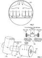
FIG.1 is an illustration of a vehicle including an aircraft, the vehicle having a passenger air distribution system that receives air from an air circulation system; -
FIG. 2 is an illustration of an air circulatory system of a vehicle including an example of an apparatus for irradiating air flow to the air circulation system; -
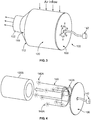
FIG. 3 is an illustration of an example of an apparatus for irradiating air flow in the air circulation system for a vehicle, such as that shown inFIGs. 1 and 2 ; -
FIG. 4 is an illustration of the apparatus inFIG. 3 depicting the ultraviolet light transmissive strands for a filter; -
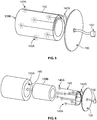
FIG. 5 is an illustration of the apparatus inFIG. 4 with the ultraviolet light transmissive strands on part of the filter; -
FIG. 6 is an assembly view of the apparatus inFIG. 5 depicting the ultraviolet light transmissive strands relative to an open end of the filter in the apparatus inFIG. 3 ; -
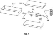
FIG. 7 is an assembly view of another example of a filter including ultraviolet light transmissive strands; -
FIG. 8 is an illustration of the example inFIG. 7 depicting the ultraviolet light transmissive strands disposed at an interface between a HEPA filter and an activated carbon filter; -
FIG. 9 is an assembly view of another example of a filter including ultraviolet light transmissive strands; and -
FIG. 10 is an illustration of a method for irradiating air within an air circulation system of a vehicle. - Corresponding reference numerals indicate corresponding parts throughout the several views of the drawings.
- Examples will now be described more fully with reference to the accompanying drawings. Examples are described of an apparatus for irradiation treatment of air within an air circulation system of a vehicle. The features, functions, and advantages discussed in the preceding section can be achieved independently in various examples or may be combined in yet other examples. Further examples of the present disclosure can be seen with reference to the drawings and the following description.
- In some examples, an apparatus for irradiation treatment of air within an air circulation system of a vehicle includes a filter unit configured to couple to a recirculating-air conduit coupled to an air circulation system, the filter unit having an inlet end. A filter is disposed in the inlet end of the filter unit, and includes an outer High Efficiency Particulate Air (HEPA) media filter, and an inner activated carbon filter media defining an interior volume. The apparatus further includes a plurality of ultraviolet light transmissive strands that each have distal ends disposed in a spaced apart manner in an interface between the outer HEPA media filter and the inner activated carbon filter, and proximal ends connectable to an ultraviolet light emitting source such that ultraviolet light is transmitted by the transmissive strands into an interface region between the outer HEPA media filter and the inner activated carbon filter. The ultraviolet light transmissive strands are configured to receive emitted ultraviolet light that is between 222 nm and 265 nm or substantially between 222 nm and 265 nm for irradiating air passing through the filter.
- Referring to
FIG. 1 , a vehicle including anaircraft 200 has a passenger air distribution system that receives air from an air circulation system. The air distribution system supplies air that enters a passenger area from overhead distribution outlets that run a length of the aircraft cabin and generate airflow in the cabin. Air supplied to the cabin contains a mixture of recirculated air from in the cabin and air from outside the aircraft. Air is drawn through air returns located near the floor along the length of the cabin, such that air is supplied to and removed from the cabin passenger area on a continuous basis. -
FIG. 2 is an illustration of anair circulation system 150 of a vehicle - such as theaircraft 200 shown inFIG. 1 - including an example of an apparatus for irradiating air flow to theair circulation system 150. Theair circulation system 150 includes a recirculating-air conduit 152 (in which a recirculating fan may be disposed) that is connected to amix manifold 154 of theair circulation system 150, where themix manifold 154 receives supply of outside air from outside theaircraft 200 from an Environmental Control System (ECS) and also receives recirculated air via filtered inputs. Themix manifold 154 also supplies two air distribution lines to supply circulated air to passengers in the cabin. -
FIG. 3 , depicts an example of anapparatus 100 for irradiation treatment of air within anair circulation system 150 such as that shown inFIG. 2 , for a vehicle such asaircraft 200 inFIG. 1 . Theapparatus 100 includes afilter unit 110 configured to couple to a recirculatingair conduit 152 connected to themix manifold 154 of theair circulation system 150, where thefilter unit 110 has aninlet end 112. Afilter 120 is disposed in theinlet end 112 of thefilter unit 110, and includes an outer High Efficiency Particulate Air (HEPA)media filter 120A and an inner activatedcarbon filter 120B (not shown inFIG. 3 ). Theapparatus 100 further includes a plurality of ultraviolet light transmissive strands that each have distal ends disposed in a spaced apart manner in an interface between the outerHEPA media filter 120A and the inner activatedcarbon filter 120B, and proximal ends connectable to an ultraviolet light emitting source such that ultraviolet light is transmitted by the transmissive strands into an interface region between the outerHEPA media filter 120A and the inner activatedcarbon filter 120B. Theapparatus 100 further comprises anend plate 130, configured to be mounted with theend plate 130 against an open end of thefilter 120, wherein the ultraviolet light transmissive strands are configured to transmit ultraviolet radiation at between 222 nm and 253 nm or substantially at between 222 nm and 253 nm for irradiating air passing through thefilter 120 into theair circulation system 150. - In an example, the
apparatus 100 includes thefilter unit 110 that is coupled to therecirculating air conduit 152, which is connected to themix manifold 154 of theair circulation system 150. Thefilter 120 is disposed at theinlet end 112 of thefilter unit 110, where thefilter 120 may have a circular, rectangular, or triangular shape and an outer surface through which air is drawn, where the filter shape defines an interior volume through which air passes through the media of thefilter 120 to the interior volume. The outer High Efficiency Particulate Air (HEPA)filter 120A may include an outer annular portion of thefilter 120 forming a pleated cartridge made with a High Efficiency Particulate Air (HEPA) media, and the inner activatedcarbon filter 120B may include an inner annular portion of thefilter 120 that includes activated carbon. Thefilter 120 may have a cylindrical shape, and may include the outer High Efficiency Particulate Air (HEPA)media 120A and the inner activatedcarbon filter media 120B defining an interior volume of thefilter 120. More specifically, in some examples, the outer pleated High Efficiency Particulate Air (HEPA)media 120A includes an outer annular portion of thefilter 120 forming a pleated cartridge made with a High Efficiency Particulate Air (HEPA) media, and the inner activatedcarbon filter media 120B includes an inner annular portion of thefilter 120 that includes activated carbon. - In an example shown in
FIG. 4 , theapparatus 100 includes a plurality of ultraviolet light transmissivestrands 140 that each havedistal ends 140A disposed in a spaced apart manner in an interface region 148 (seeFIG. 6 ) between the outerHEPA media filter 120A and the inner activatedcarbon filter 120B, and proximal ends connectable to an ultraviolet light emitting source such that ultraviolet light is transmitted by the transmissive strands into theinterface region 148 between the outerHEPA media filter 120A and the inner activatedcarbon filter 120B. The ultraviolet light transmissivestrands 140 may be overlaid on or disposed on an outer surface of the inner activatedcarbon filter 120B, such that the distal ends 140A of the plurality of ultraviolet light transmissivestrands 140 are positioned in a spaced apart manner along an outer surface of the activatedcarbon filter 120B, as shown inFIG. 5 . Thetransmissive strands 140 overlaid on the activatedcarbon filter 120B are then positioned within the outer High Efficiency Particulate Air (HEPA)media filter 120A, as shown inFIG. 6 , such that the distal ends 140A of the plurality of ultraviolet light transmissivestrands 140 are disposed along theinterface region 148 between the outerHEPA media filter 120A and the inner activatedcarbon filter 120B. In some examples, the distal ends 140A of the plurality of ultraviolet light transmissivestrands 140 are removably disposed between the outerHEPA media filter 120A and the inner activatedcarbon filter 120B, such that they can be removed and replaced. The proximal end of each of the plurality of ultraviolet light transmissivestrands 140 are connected to an ultraviolet light emitting source, such that ultraviolet light emitted by the source is transmitted by thetransmissive strands 140 into theinterface region 148 between the outerHEPA media filter 120A and the inner activatedcarbon filter 120B. Thefilter 120 including the ultraviolet light transmissivestrands 140 is positioned relative to thefilter unit 110, and theend plate 130 is positioned against the open end of thefilter 120. - The distal ends 140A of the plurality of ultraviolet light transmissive
strands 140 may each be of varying lengths, such that the distal ends 140A are positioned at different locations within theinterface region 148 between the outerHEPA media filter 120A and the inner activatedcarbon filter 120B. The distal ends 140A of the plurality of ultraviolet light transmissivestrands 140 may be positioned at various locations within theinterface region 148 between the outerHEPA media filter 120A and the inner activatedcarbon filter 120B, such that ultraviolet light is scattered throughout theinterface region 148. In some examples, the outerHEPA media filter 120A is made of woven fiberglass, where the transmitted ultraviolet light emitted at theinterface region 148 is reflected and scattered by the woven fiberglass to disperse UV light and irradiate theinterface region 148 between the outerHEPA media filter 120A and the inner activatedcarbon filter 120B. In some examples, the proximal ends of the plurality of ultraviolet light transmissivestrands 140 are joined into a single strand that is positioned relative to an ultraviolet light source, and may be connected to a connector proximate to theend plate 130. In some examples, the ultraviolet light source emits ultraviolet radiation at between 222 nm and 265 nm at a power flux or irradiation of at least 1,000 microwatts per square centimeter, such that the intensity of ultraviolet radiation is sufficient to kill and/or degrade microorganisms, viruses, bacteria, germs, mold, and other contaminants in the air flowing through the filter. In some examples, the plurality of ultraviolet light transmissivestrands 140 include optical fibers suitable for fiber-optic transmission of ultraviolet light. One such optical fiber is Molex® Silica Optical Fiber sold by Laser Components. In some examples, theapparatus 100 further includes, as an ultraviolet light source, an ultraviolet light emitting diode (LED) positioned relative to the proximal ends of the plurality of ultraviolet light transmissivestrands 140 including optical fibers, where the ultraviolet LED emits ultraviolet light into the proximal ends of the ultraviolet light transmissivestrands 140, which transmit the ultraviolet light to theinterface region 148 to irradiate the air passing through the outerHEPA media filter 120A, theinterface region 148, and the inner activatedcarbon filter 120B into theair circulation system 150. An example may be an ultraviolet LED part number VPS134 sold by Boston Scientific. In some examples, the ultraviolet light source is configured to emit a distribution of frequencies of ultraviolet radiation ranging at between 222 nm and 265 nm or substantially at between 222 nm and 265 nm, where the range is sufficient to result in generation of a minimal amount of ozone. An ultraviolet light source having a wavelength below 240 nm can generate ozone, while an ultraviolet light source having an emission frequency in the range of 240 nm to 265 nm (or about 240 nm to 265 nm) can potentially destroy ozone or reduce the level of ozone, where the emission of a range of ultraviolet radiation up to a frequency of 265 nm potentially reduces or limits the extent of ozone generated by emitted UV radiation at lower frequencies, such that the distribution of frequencies in the range of between 222 nm and 265 nm results in generation of a minimal amount of ozone within thefilter 120. Thefilter 120 including the ultraviolet light transmissivestrands 140 is positioned relative to thefilter unit 110, and anend plate 130 is positioned against the open end of thefilter 120. Theend plate 130 shown inFIG. 6 is, in some examples, configured to be mounted by attachment via rivets, adhesive, or bonding to the end of thefilter 120. - Referring to
FIG. 7 , another example is shown of a filter (e.g., the filter 120) including ultraviolet light transmissivestrands 140, which may be included in theapparatus 100 for irradiating air in an air circulation system (e.g., the air circulation system 150). The filter includes a filter unit 110 (or filter housing), a plurality of ultraviolet light transmissivestrands 140, aHEPA filter 120A, and an activatedcarbon filter 120B. As shown inFIG. 8 , the distal ends 140A of the plurality of ultraviolet light transmissivestrands 140 are positioned within aninterface region 148 between theHEPA filter 120A and an activatedcarbon filter 120B such that the plurality of ultraviolet light transmissivestrands 140 are disposed between theHEPA filter 120A and the activatedcarbon filter 120B. The proximal ends of the plurality of ultraviolet light transmissivestrands 140 pass through a sealed connection in thefilter unit 110, where an ultraviolet light source may be positioned relative to (or connected to) the plurality of ultraviolet light transmissivestrands 140 such that ultraviolet light emitted by the source is transmitted by the plurality of ultraviolet light transmissivestrands 140. - Additionally, the
apparatus 100 may be configured to include a controller (not shown) that monitors an air flow sensor, mass flow sensor, or air particulate sensor disposed within the cabin of the aircraft (e.g.,aircraft 200, shown inFIG. 1 ), to determine if the amount of recirculated irradiated air flow through the aircraft cabin is indicative of a minimum level for removing airborne particulates and contaminates, and thereafter discontinuing supply of power to the ultraviolet light source positioned relative to (or connected to) the plurality of ultraviolet light transmissivestrands 140. Similarly, the controller can monitor the sensor to determine if a measurement is indicative of the presence of more than an acceptable threshold of ozone or contaminant particulates are present in the cabin air, and thereafter deactivating the ultraviolet light emitter to discontinue ultraviolet light irradiation. Additionally, the controller may monitor the sensor to determine if the amount of recirculated irradiated air flow through the aircraft cabin is indicative of an insufficient level for removing airborne particulates and contaminates, and thereafter initiate the supply of power to the ultraviolet light to emit ultraviolet radiation at between 222 nm and 265 nm to irradiate the air flow through thefilter 120 into theair circulation system 150. - According to other examples, a method for irradiating air within an air circulation system of a vehicle includes coupling a filter unit to a recirculating-air conduit that is connected to a manifold of an air circulation system, the filter unit having an inlet end. The method further includes positioning the distal ends of a plurality of ultraviolet light transmissive strands in a spaced apart manner along an outer surface of an activated carbon filter, and positioning the activated carbon filter within a High Efficiency Particulate Air (HEPA) media filter, such that the distal ends of a plurality of ultraviolet light transmissive strands are disposed along an interface region between the outer HEPA media filter and the inner activated carbon filter. The method further includes securing the filter including the ultraviolet light transmissive strands relative to the filter unit, and connecting a proximal end of each of the plurality of ultraviolet light transmissive strands to an ultraviolet light emitting source such that ultraviolet light emitted by the source is transmitted by the transmissive strands into an interface region between the outer HEPA media filter and the inner activated carbon filter. The method further includes activating the ultraviolet light emitting source, to cause the ultraviolet light source to emit ultraviolet radiation at between 222 nm and 265 nm or substantially at between 222 nm and 265 nm that is transmitted by the transmissive strands for irradiating air passing through the filter into the air circulation system.
- As illustrated in
FIG. 10 , an example of a method is provided for irradiating air within an air circulation system of a vehicle. The method includes atstep 300 coupling a filter unit to a recirculating-air conduit that is connected to a manifold of an air circulation system, the filter unit having an inlet end. The method includes, atstep 302, positioning the distal ends of a plurality of ultraviolet light transmissive strands in a spaced apart manner along an outer surface of an activated carbon filter. The method further includes, atstep 304, positioning the activated carbon filter within a High Efficiency Particulate Air (HEPA) media filter, such that the distal ends of a plurality of ultraviolet light transmissive strands are disposed along an interface region between the outer HEPA media filter and the inner activated carbon filter. Atstep 306, the method includes securing the filter including the ultraviolet light transmissive strands relative to the filter unit, and an end plate positioned against an open end of the filter. The method may optionally include thestep 308 of providing an ultraviolet light source that emits ultraviolet radiation at between 222 nm and 265 nm and a predetermined power level such that an intensity of the ultraviolet radiation is sufficient to kill and/or degrade viruses, bacteria, and other airborne microorganisms. The method further includes, atstep 310, connecting a proximal end of each of the plurality of ultraviolet light transmissive strands to an ultraviolet light emitting source such that activation of the source causes ultraviolet light emitted by the source to be transmitted by the transmissive strands into an interface region between the outer HEPA media filter and the inner activated carbon filter, for irradiating air flow passing through the filter into an air circulation system. The method further includes, atstep 312, activating the ultraviolet light emitting source, to cause the ultraviolet light source to emit ultraviolet radiation at between 222 nm and 265 nm or substantially at between 222 nm and 265 nm that is transmitted by the transmissive strands for irradiating air passing through the filter into the air circulation system. The method may optionally include thestep 314 of activating the ultraviolet light source to emit ultraviolet radiation at a predetermined power level for a predetermined period of time, such that a sufficient amount of irradiate recirculating air flows through the air circulation system and aircraft cabin before further flight operation of the aircraft. - The examples fully convey the scope to those who are skilled in the art. Numerous specific details are set forth such as examples of specific components, devices, and methods, to provide a thorough understanding of examples of the present disclosure. It will be apparent to those skilled in the art that specific details need not be employed, that examples may be embodied in many different forms and that neither should be construed to limit the scope of the disclosure. In some examples, well-known processes, well-known device structures, and well-known technologies are not described in detail.
- Further, the disclosure comprises examples according to the following clauses:
- Clause 1. An apparatus (100) for irradiating air in an air circulation system (150) of a vehicle, the apparatus (100) comprising: a filter unit (110) configured to couple to a recirculating air conduit (152) connected to the air circulation system (150), the filter unit (110) having an inlet end (112); a filter (120) disposed in the inlet end (112) of the filter unit (110), comprising an outer High Efficiency Particulate Air (HEPA) media filter (120A), and an inner activated carbon filter (120B) defining an interior volume of the filter (120); a plurality of ultraviolet light transmissive strands (140) that each have distal ends (140A) disposed in a spaced apart manner in an interface between the outer HEPA media filter (120A) and the inner activated carbon filter (120B), and proximal ends connectable to an ultraviolet light emitting source such that ultraviolet light is transmitted by the plurality of ultraviolet light transmissive strands (140) into an interface region (148) between the outer HEPA media filter (120A) and the inner activated carbon filter (120B); and an end plate (130) disposed over an open end of the filter (120), having an aperture though which the plurality of ultraviolet light transmissive strands (140) extend, wherein the ultraviolet light transmissive strands (140) are configured to receive emitted ultraviolet light that is at between 222 nm and 265 nm or substantially at between 222 nm and 265 nm, and to transmit the ultraviolet light into the air passing through the interface between the outer HEPA media filter (120A) and the inner activated carbon filter (120B) and into the air circulation system (150).
-
Clause 2. The apparatus (100) of Clause 1, wherein the ultraviolet light is configured to emit a distribution of frequencies of ultraviolet radiation ranging between 222 nm and 265 nm or substantially between 222 nm and 265 nm, where the range is sufficient to result in generation of a minimal amount of ozone. - Clause 3. The apparatus (100) of either
Clause 1 or 2, wherein the distal ends (140A) of the plurality of ultraviolet light transmissive strands (140) are positioned at different locations within the interface between the outer HEPA media filter (120A) and the inner activated carbon filter (120B), such that the ultraviolet light is scattered throughout the interface, and wherein the proximal ends of the plurality of ultraviolet light transmissive strands (140) are joined into a single strand that is connected to a connector proximate to the end plate (130). - Clause 4. The apparatus (100) of Clause 3, wherein the ultraviolet light emitting source emits ultraviolet radiation at between 222nm and 265 nm at a power flux or irradiation of at least 1,000 microwatts per square centimeter, such that the intensity of ultraviolet radiation is sufficient to kill and/or degrade microorganisms, viruses, bacteria, germs, mold, and other contaminants in the air flowing through the interior volume of the filter (120).
- Clause 5. The apparatus (100) of any of Clauses 1 to 4, wherein each of the distal ends (140A) of the plurality of ultraviolet light transmissive strands (140) are of varying lengths, such that the distal ends (140A) are positioned at different locations within the interface between the outer HEPA media filter (120A) and the inner activated carbon filter (120B).
- Clause 6. The apparatus (100) of any of Clauses 1 to 5, wherein the plurality of ultraviolet light transmissive strands (140) comprise optical fibers suitable for fiber-optic transmission of ultraviolet light.
- Clause 7. The apparatus (100) of Clause 6, further comprising an ultraviolet light emitting diode (LED) positioned relative to the proximal ends of the plurality of ultraviolet light transmissive strands (140) comprising optical fibers, where the ultraviolet light emitting diode emits ultraviolet light into the proximal ends of the optical fibers that transmit the ultraviolet light to irradiate the air passing through the outer HEPA media filter (120A), the interface region (148) and the inner activated carbon filter (120B) into the air circulation system (150).
-
Clause 8. The apparatus (100) of any of Clauses 1 to 7, wherein the end plate (130) is configured to be mounted by attachment via rivets, adhesive, or bonding to an open end of the filter (120). - Clause 9. The apparatus (100) of any of Clauses 1 to 8, wherein the outer HEPA media (120A) comprises an outer annular portion of the filter (120) forming a pleated cartridge made with a HEPA media.
- Clause 10. The apparatus (100) of any of Clauses 1 to 9, wherein the inner activated carbon filter (120B) comprises an inner annular portion of the filter (120) that includes activated carbon.
- Clause 11. The apparatus (100) of Clause 10, wherein the filter unit (110) is configured to couple to a recirculating air conduit (152) that is connected to the manifold (154) of the air circulation system (150) of a vehicle, and wherein the filter unit (110) filters recirculating air supplied to the manifold (154).
- Clause 12. The apparatus (100) of Clause 11, wherein the manifold (154) is a mixing manifold of the air circulating system (150) on board an aircraft (200).
- Clause 13. A method for irradiating air in an air circulation system (150) of a vehicle, comprising the steps of: coupling (300) a filter unit (110) to a recirculating-air conduit (152) that is connected to a manifold (154) of the air circulation system (150), the filter unit (110) having an inlet end (112); positioning (302) distal ends (140A) of a plurality of ultraviolet light transmissive strands (140) in a spaced apart manner along an outer surface of an inner activated carbon filter (120B) of a filter (120); positioning (304) the inner activated carbon filter (120B) within an outer High Efficiency Particulate Air (HEPA) media filter (120A) of the filter (120), such that the distal ends (140A) of the plurality of ultraviolet light transmissive strands (140) are disposed along an interface region (148) between the outer HEPA media filter (120A) and the inner activated carbon filter (120B); securing (306) the filter (120) including the ultraviolet light transmissive strands (140) relative to the filter unit (110), and an end plate (130) positioned against an open end of the filter (120); connecting (310) a proximal end of each of the plurality of ultraviolet light transmissive strands (140) to an ultraviolet light emitting source such that ultraviolet light emitted by the source is transmitted by the plurality of ultraviolet light transmissive strands (140) into an interface region (148) between the outer HEPA media filter (120A) and the inner activated carbon filter (120B); and activating (312) the ultraviolet light emitting source, to cause the ultraviolet light emitting source to emit ultraviolet radiation at between 222 nm and 265 nm or substantially at between 222 nm and 265 nm that is transmitted by the plurality of ultraviolet light transmissive strands (140) for irradiating air passing through the filter (120) into the air circulation system (150).
- Clause 14. The method of Clause 13, wherein the step of positioning the distal ends (140A) comprises positioning the distal ends (140A) at different locations within the interface region (148) between the outer HEPA media filter (120A) and the inner activated carbon filter (120B), such that the ultraviolet light is scattered throughout the interface region (148), and wherein the method further comprises the step of positioning the proximal ends of the plurality of ultraviolet light transmissive strands (140), comprising joining the plurality of ultraviolet light transmissive strands (140) into a single bundled strand such that the ultraviolet light emitting source emits ultraviolet light into the plurality of ultraviolet light transmissive strands (140).
- Clause 15. The method of Clause 14, wherein the step of activating the ultraviolet light emitting source comprises operating an ultraviolet light emitting diode that emits ultraviolet radiation at between 222 nm and 265 nm, at a power flux or irradiation of at least 1,000 microwatts per square centimeter, such that an intensity of ultraviolet radiation irradiating the air passing through the filter (120) is sufficient to kill and/or degrade microorganisms, viruses, bacteria, germs, mold and other contaminants in the air flowing through the filter (120).
- Clause 16. The method of any of Clauses 13 to 15, wherein the method further comprises coupling the filter housing to a recirculating air conduit (152) that is connected to the manifold (154) of the air circulation system (150) of an aircraft (200), for enabling supply of irradiated recirculating air to the manifold (154) of the air circulation system (150) for the aircraft (200).
- Clause 17. The method of any of Clauses 13 to 16, further comprising the step of powering the ultraviolet light to power the ultraviolet light with a power flux or irradiation of at least 1,000 microwatts per square centimeter, for a predetermined period of time, such that a sufficient amount of irradiated recirculating air flows through the manifold (154) and is recirculated through a cabin of the vehicle before further operation of the vehicle.
- Clause 18. The method of Clause 17, further comprising the step of monitoring a sensor disposed within the cabin of the vehicle to determine if the amount of recirculated irradiated air flow through the cabin of the vehicle is indicative of a minimum level for removing airborne particulates and contaminates, and thereafter discontinuing supply of power to the ultraviolet light.
- Clause 19. The method of Clause 18, further comprising monitoring a sensor disposed within the cabin of the vehicle to determine if a measurement of recirculated irradiated air flow through the cabin of the vehicle is indicative of an insufficient level for removing airborne particulates and contaminates, and thereafter supplying power to the ultraviolet light to emit ultraviolet radiation at between 222 nm and 265 nm to irradiate the air flow through the filter (120) into the air circulation system (150).
- Clause 20. An apparatus (100) for irradiating air in an air circulation system (150) of a vehicle, the apparatus (100) comprising: a filter unit (110) for coupling to a recirculating air conduit (152) of the air circulation system (150), the filter unit (110) having an inlet end (112); a filter (120) disposed in the inlet end (112) of the filter unit (110), comprising an outer High Efficiency Particulate Air (HEPA) media filter (120A), and an inner activated carbon filter (120B) defining an interior volume of the filter (120); a plurality of ultraviolet light transmissive strands (140) that each have distal ends (140A) disposed in a spaced apart manner in an interface between the outer HEPA media filter (120A) and the inner activated carbon filter (120B), and proximal ends configured for connection to an ultraviolet light emitting source such that ultraviolet light is transmitted by the plurality of ultraviolet light transmissive strands (140) into an interface region (148) between the outer HEPA media filter (120A) and the inner activated carbon filter (120B); and an end plate (130) disposed over an open end of the filter (120), having an aperture though which the plurality of ultraviolet light transmissive strands (140) extend; and wherein the ultraviolet light transmissive strands (140) are configured to receive ultraviolet light emitted by the ultraviolet light emitting source that is substantially at between 222 nm and 265 nm, and to transmit the ultraviolet light into the air passing through the interface between the outer HEPA media filter (120A) and the inner activated carbon filter (120B) and into the air circulation system (150).
- Clause 21. The apparatus (100) of Clause 20, wherein: the ultraviolet light emitting source is configured to emit a distribution of frequencies of ultraviolet light ranging substantially between 222 nm and 265 nm; or the ultraviolet light emitting source is configured to emit a distribution of frequencies of ultraviolet light ranging substantially between 222 nm and 265 nm, where the range is sufficient to result in generation of a minimal amount of ozone.
- Clause 22. The apparatus (100) of either Clause 20 or 21, wherein: the distal ends (140A) of the plurality of ultraviolet light transmissive strands (140) are positioned at different locations within the interface between the outer HEPA media filter (120A) and the inner activated carbon filter (120B), such that, in use, the ultraviolet light is scattered throughout the interface; and the proximal ends of the plurality of ultraviolet light transmissive strands (140) are joined into a single strand that is connected to a connector proximate to the end plate (130).
- Clause 23. The apparatus (100) of any of Clauses 20 to 22, wherein: the ultraviolet light emitting source emits ultraviolet radiation at between 222 nm and 265 nm at a power flux or irradiation of at least 1,000 microwatts per square centimeter; or the ultraviolet light emitting source emits ultraviolet radiation at between 222 nm and 265 nm at a power flux or irradiation of at least 1,000 microwatts per square centimeter, such that the intensity of ultraviolet radiation is sufficient to kill and/or degrade microorganisms, viruses, bacteria, germs, mold, and other contaminants in the air flowing through the interior volume of the filter (120).
- Clause 24. The apparatus (100) of any of Clauses 20 to 23, wherein: each of the distal ends (140A) of the plurality of ultraviolet light transmissive strands (140) are of varying lengths, such that the distal ends (140A) are positioned at different locations within the interface between the outer HEPA media filter (120A) and the inner activated carbon filter (120B).
- Clause 25. The apparatus (100) of any of Clauses 20 to 24, wherein the plurality of ultraviolet light transmissive strands (140) comprise optical fibers suitable for fiber-optic transmission of ultraviolet light.
- Clause 26. The apparatus (100) of Clause 25, wherein the ultraviolet light emitting source comprises an ultraviolet light emitting diode (LED) positioned relative to the proximal ends of the optical fibers such that the ultraviolet light emitting diode emits ultraviolet light into the proximal ends of the optical fibers that transmit the ultraviolet light to irradiate the air passing through the outer HEPA media filter (120A), the interface region (148) and the inner activated carbon filter (120B) into the air circulation system (150)
- Clause 27. The apparatus (100) of any of Clauses 20 to 26, wherein the end plate (130) is configured to be mounted by attachment via rivets, adhesive, or bonding to an open end of the filter (120).
- Clause 28. The apparatus (100) of any of Clauses 20 to 27, wherein the outer HEPA media (120A) comprises an outer annular portion of the filter (120) forming a pleated cartridge made with a HEPA media.
- Clause 29. The apparatus (100) of any of Clauses 20 to 28, wherein the inner activated carbon filter (120B) comprises an inner annular portion of the filter (120) that includes activated carbon.
- Clause 30. A vehicle comprising: an air circulation system (150); and the apparatus (100) of any of Clauses 20 to 29 configured to irradiate air in the air circulation system (150); and wherein: the filter unit (110) is coupled to a recirculating air conduit (152) of the air circulation system (150).
- Clause 31. The vehicle of Clause 30, wherein: the recirculating air conduit (152) is connected to a mixing manifold (154) of the air circulation system (150); and the filter unit (110) is operable to filter recirculating air supplied to the manifold (154).
- Clause 32. The vehicle of Clause 30 or 31, wherein the vehicle is an aircraft (200), a train, a coach or a bus.
- Clause 33. A method for installing the apparatus of any of Clauses 1 to 12 or Clauses 20 to 29 in an air circulation system (150) of a vehicle, optionally an aircraft (200), the method comprising the steps of: coupling (300) the filter unit (110) to a recirculating-air conduit (152) that is connected to a manifold (154) of the air circulation system (150); positioning (302) the distal ends (140A) of the plurality of ultraviolet light transmissive strands (140) in a spaced apart manner along an outer surface of an inner activated carbon filter (120B) of a filter (120); positioning (304) the inner activated carbon filter (120B) within the outer High Efficiency Particulate Air (HEPA) media filter (120A) of the filter (120), such that the distal ends (140A) of the plurality of ultraviolet light transmissive strands (140) are disposed along the interface region (148) between the outer HEPA media filter (120A) and the inner activated carbon filter (120B); securing (306) the filter (120) including the ultraviolet light transmissive strands (140) relative to the filter unit (110), and the end plate (130) positioned against the open end of the filter (120); and connecting (310) the proximal end of each of the plurality of ultraviolet light transmissive strands (140) to the ultraviolet light emitting source such that ultraviolet light emitted by the ultraviolet light emitting source is transmitted by the plurality of ultraviolet light transmissive strands (140) into the interface region (148) between the outer HEPA media filter (120A) and the inner activated carbon filter (120B).
- Clause 34. The method of Clause 33, wherein the step of positioning the distal ends (140A) comprises positioning the distal ends (140A) at different locations within the interface region (148) between the outer HEPA media filter (120A) and the inner activated carbon filter (120B), such that the ultraviolet light is scattered throughout the interface region (148), and wherein the method further comprises the step of positioning the proximal ends of the plurality of ultraviolet light transmissive strands (140), comprising joining the plurality of ultraviolet light transmissive strands (140) into a single bundled strand such that the ultraviolet light emitting source emits ultraviolet light into the plurality of ultraviolet light transmissive strands (140).
- Clause 35. The method of Clause 33 or 34 wherein the method further comprises coupling the filter housing to a recirculating air conduit (152) that is connected to the manifold (154) of the air circulation system (150) of an aircraft (200), for enabling supply of irradiated recirculating air to the manifold (154) of the air circulation system (150) for the aircraft (200).
- Clause 36. A method for irradiating air in an air circulation system (150) of a vehicle using the apparatus of any of Clauses 1 to 12 or Clauses 20 to 29, the method comprising the steps of: coupling (300) the filter unit (110) to a recirculating-air conduit (152) that is connected to a manifold (154) of the air circulation system (150); and activating (312) the ultraviolet light emitting source, to cause the ultraviolet light emitting source to emit ultraviolet light substantially at between 222 nm and 265 nm that is transmitted by the plurality of ultraviolet light transmissive strands (140) for irradiating air passing through the filter (120) into the air circulation system (150).
- Clause 37. The method of Clause 36, wherein the step of activating the ultraviolet light emitting source comprises: operating an ultraviolet light emitting diode that emits the ultraviolet light at between 222 nm and 265 nm, at a power flux or irradiation of at least 1,000 microwatts per square centimeter; or operating an ultraviolet light emitting diode that emits the ultraviolet light at between 222 nm and 265 nm, at a power flux or irradiation of at least 1,000 microwatts per square centimeter, such that an intensity of the ultraviolet light irradiating the air passing through the filter (120) is sufficient to kill and/or degrade microorganisms, viruses, bacteria, germs, mold and other contaminants in the air flowing through the filter (120).
- Clause 38. The method of Clause 36 or 37, further comprising the step of powering the ultraviolet light to power the ultraviolet light emitting source with a power flux or irradiation of at least 1,000 microwatts per square centimeter, for a predetermined period of time, such that irradiated recirculating air flows through the manifold (154) and is recirculated through a cabin of the vehicle.
- Clause 39. The method of Clause 38, further comprising monitoring a sensor disposed within the cabin of the vehicle to determine if a measurement of recirculated irradiated air flow through the cabin of the vehicle is indicative of an insufficient level for removing airborne particulates and contaminates, and thereafter supplying power to the ultraviolet light emitting source to emit ultraviolet light at between 222 nm and 265 nm to irradiate the air flow through the filter (120) into the air circulation system (150).
- Clause 40. The method of Clause 39, further comprising monitoring the sensor to determine if the amount of recirculated irradiated air flow through the cabin of the vehicle is indicative of a minimum level for removing airborne particulates and contaminates, and thereafter discontinuing supply of power to the ultraviolet light.
- Clause 41. The method of any of claims 36 to 40, wherein the vehicle is an aircraft (200).
- The terminology used herein is for the purpose of describing particular example examples only and is not intended to be limiting. As used herein, the singular forms "a," "an," and "the" may be intended to include the plural forms as well, unless the context clearly indicates otherwise. The terms "comprises," "comprising," "including," and "having," are inclusive and therefore specify the presence of stated features, integers, steps, operations, elements, and/or components, but do not preclude the presence or addition of one or more other features, integers, steps, operations, elements, components, and/or groups thereof. The method steps, processes, and operations described herein are not to be construed as necessarily requiring their performance in the particular order discussed or illustrated, unless specifically identified as an order of performance. It is also to be understood that additional or alternative steps may be employed.
- The foregoing description of the examples has been provided for purposes of illustration and description. It is not intended to be exhaustive or to limit the present disclosure. Individual elements or features of a particular example are generally not limited to that particular example, but, where applicable, are interchangeable and can be used in a selected example, even if not specifically shown or described. The same may also be varied in many ways. Such variations are not to be regarded as a departure from the disclosure, and all such modifications are intended to be included within the scope of the disclosure.
Claims (15)
- An apparatus (100) for irradiating air in an air circulation system (150) of a vehicle, the apparatus (100) comprising:a filter unit (110) for coupling to a recirculating air conduit (152) of the air circulation system (150), the filter unit (110) having an inlet end (112);a filter (120) disposed in the inlet end (112) of the filter unit (110), comprising an outer High Efficiency Particulate Air (HEPA) media filter (120A), and an inner activated carbon filter (120B) defining an interior volume of the filter (120);a plurality of ultraviolet light transmissive strands (140) that each have distal ends (140A) disposed in a spaced apart manner in an interface between the outer HEPA media filter (120A) and the inner activated carbon filter (120B), and proximal ends configured for connection to an ultraviolet light emitting source such that ultraviolet light is transmitted by the plurality of ultraviolet light transmissive strands (140) into an interface region (148) between the outer HEPA media filter (120A) and the inner activated carbon filter (120B); andan end plate (130) disposed over an open end of the filter (120), having an aperture though which the plurality of ultraviolet light transmissive strands (140) extend; andwherein the ultraviolet light transmissive strands (140) are configured to receive ultraviolet light emitted by the ultraviolet light emitting source that is substantially at between 222 nm and 265 nm, and to transmit the ultraviolet light into the air passing through the interface between the outer HEPA media filter (120A) and the inner activated carbon filter (120B) and into the air circulation system (150).
- The apparatus (100) of claim 1, wherein the ultraviolet light emitting source is configured to emit a distribution of frequencies of ultraviolet light ranging substantially between 222 nm and 265 nm.
- The apparatus (100) of either claim 1 or 2, wherein:the distal ends (140A) of the plurality of ultraviolet light transmissive strands (140) are positioned at different locations within the interface between the outer HEPA media filter (120A) and the inner activated carbon filter (120B), such that, in use, the ultraviolet light is scattered throughout the interface; andthe proximal ends of the plurality of ultraviolet light transmissive strands (140) are joined into a single strand that is connected to a connector proximate to the end plate (130).
- The apparatus (100) of any of claims 1 to 3, wherein the ultraviolet light emitting source emits ultraviolet light at between 222 nm and 265 nm at a power flux or irradiation of at least 1,000 microwatts per square centimeter.
- The apparatus (100) of any of claims 1 to 4, wherein:
each of the distal ends (140A) of the plurality of ultraviolet light transmissive strands (140) are of varying lengths, such that the distal ends (140A) are positioned at different locations within the interface between the outer HEPA media filter (120A) and the inner activated carbon filter (120B). - The apparatus (100) of any of claims 1 to 5, wherein:the plurality of ultraviolet light transmissive strands (140) comprise optical fibers suitable for fiber-optic transmission of ultraviolet light; and, optionally,the ultraviolet light emitting source comprises an ultraviolet light emitting diode (LED) positioned relative to the proximal ends of the optical fibers such that the ultraviolet light emitting diode emits ultraviolet light into the proximal ends of the optical fibers that transmit the ultraviolet light to irradiate the air passing through the outer HEPA media filter (120A), the interface region (148) and the inner activated carbon filter (120B) into the air circulation system (150).
- The apparatus (100) of any of claims 1 to 6, wherein the outer HEPA media (120A) comprises an outer annular portion of the filter (120) forming a pleated cartridge made with a HEPA media and the inner activated carbon filter (120B) comprises an inner annular portion of the filter (120) that includes activated carbon.
- A vehicle, optionally an aircraft (200), comprising:an air circulation system (150); andthe apparatus (100) of any of claims 1 to 7 configured to irradiate air in the air circulation system (150); and wherein:
the filter unit (110) is coupled to a recirculating air conduit (152) of the air circulation system (150). - The vehicle of claim 8, wherein:the recirculating air conduit (152) is connected to a mixing manifold (154) of the air circulation system (150); andthe filter unit (110) is operable to filter recirculating air supplied to the mixing manifold (154).
- A method for irradiating air in an air circulation system (150) of a vehicle using the apparatus of any of claims 1 to 7, the method comprising the steps of:coupling (300) the filter unit (110) to a recirculating-air conduit (152) that is connected to a manifold (154) of the air circulation system (150); andactivating (312) the ultraviolet light emitting source, to cause the ultraviolet light emitting source to emit ultraviolet light substantially at between 222 nm and 265 nm that is transmitted by the plurality of ultraviolet light transmissive strands (140) for irradiating air passing through the filter (120) into the air circulation system (150).
- The method of claim 10, wherein the step of activating the ultraviolet light emitting source comprises operating an ultraviolet light emitting diode that emits the ultraviolet light at between 222 nm and 265 nm, at a power flux or irradiation of at least 1,000 microwatts per square centimeter.
- The method of claim 10 or 11, further comprising the step of powering the ultraviolet light to power the ultraviolet light emitting source with a power flux or irradiation of at least 1,000 microwatts per square centimeter, for a predetermined period of time, such that irradiated recirculating air flows through the manifold (154) and is recirculated through a cabin of the vehicle.
- The method of claim 12, further comprising monitoring a sensor disposed within the cabin of the vehicle to determine if a measurement of recirculated irradiated air flow through the cabin of the vehicle is indicative of an insufficient level for removing airborne particulates and contaminates, and thereafter supplying power to the ultraviolet light emitting source to emit ultraviolet light at between 222 nm and 265 nm to irradiate the air flow through the filter (120) into the air circulation system (150).
- The method of claim 13, further comprising monitoring the sensor to determine if the amount of recirculated irradiated air flow through the cabin of the vehicle is indicative of a minimum level for removing airborne particulates and contaminates, and thereafter discontinuing supply of power to the ultraviolet light.
- The method of any of claims 10 to 14, wherein the vehicle is an aircraft (200).
Applications Claiming Priority (2)
| Application Number | Priority Date | Filing Date | Title |
|---|---|---|---|
| US202063041717P | 2020-06-19 | 2020-06-19 | |
| US17/192,395 US12097310B2 (en) | 2020-06-19 | 2021-03-04 | Apparatus and method for irradiating air in an air circulation system of a vehicle |
Publications (2)
| Publication Number | Publication Date |
|---|---|
| EP3925882A1 true EP3925882A1 (en) | 2021-12-22 |
| EP3925882B1 EP3925882B1 (en) | 2024-11-13 |
Family
ID=75728679
Family Applications (1)
| Application Number | Title | Priority Date | Filing Date |
|---|---|---|---|
| EP21170882.1A Active EP3925882B1 (en) | 2020-06-19 | 2021-04-28 | Apparatus and method for irradiating air in an air circulation system of a vehicle |
Country Status (4)
| Country | Link |
|---|---|
| US (1) | US12097310B2 (en) |
| EP (1) | EP3925882B1 (en) |
| JP (1) | JP7851695B2 (en) |
| CN (1) | CN113813703B (en) |
Families Citing this family (5)
| Publication number | Priority date | Publication date | Assignee | Title |
|---|---|---|---|---|
| US11904267B2 (en) * | 2020-06-19 | 2024-02-20 | The Boeing Company | Apparatus and method for irradiating air in an air circulation system of a vehicle |
| US12097310B2 (en) | 2020-06-19 | 2024-09-24 | The Boeing Company | Apparatus and method for irradiating air in an air circulation system of a vehicle |
| US20230256269A1 (en) * | 2020-06-30 | 2023-08-17 | Jay Clarke Hanan | Anti-viral breathing and oxygen supplying apparatus |
| US12281974B2 (en) * | 2020-11-06 | 2025-04-22 | Carrier Corporation | Air quality and particulate detection system |
| JP7382665B1 (en) | 2022-05-17 | 2023-11-17 | 株式会社 リブレックス | air purifying filter |
Citations (5)
| Publication number | Priority date | Publication date | Assignee | Title |
|---|---|---|---|---|
| JPH10249128A (en) * | 1997-03-14 | 1998-09-22 | Fukuhara:Kk | Air compressor and sterilizer with sterilizer |
| KR20120047175A (en) * | 2010-11-03 | 2012-05-11 | 엘지이노텍 주식회사 | Air cleaner with ultra violet light emitting diode |
| CN103446879A (en) * | 2013-09-05 | 2013-12-18 | 天津大学 | Sleeve type photocatalysis air cleaning device based on dispersion optical fibers |
| US20180250430A1 (en) * | 2017-03-02 | 2018-09-06 | Hound Tech Llc | Air monitoring and filtration device for detecting and removing odors |
| US20190009912A1 (en) * | 2015-08-31 | 2019-01-10 | Tokuyama Corporation | Method for air conditioning of aircraft, and air conditioning system therefor |
Family Cites Families (16)
| Publication number | Priority date | Publication date | Assignee | Title |
|---|---|---|---|---|
| US5399319A (en) * | 1993-08-02 | 1995-03-21 | Vector Technologies Ltd. | Apparatus for filtering air and for creating a positive/negative pressure |
| JP3383932B2 (en) * | 1996-02-27 | 2003-03-10 | 飯村 惠次 | Photocatalyst device |
| US5997619A (en) * | 1997-09-04 | 1999-12-07 | Nq Environmental, Inc. | Air purification system |
| JPH11290695A (en) * | 1998-04-10 | 1999-10-26 | Sumitomo Electric Ind Ltd | Photocatalytic filter |
| US6783578B2 (en) | 2002-12-17 | 2004-08-31 | Isolate, Inc. | Air purification unit |
| JP2005297720A (en) * | 2004-04-09 | 2005-10-27 | Mayekawa Mfg Co Ltd | Air cleaner |
| US8417352B2 (en) * | 2004-10-19 | 2013-04-09 | Meagan Medical, Inc. | System and method for stimulating sensory nerves |
| JP2008086599A (en) * | 2006-10-03 | 2008-04-17 | H & C Gijutsu Kenkyusho:Kk | Air sterilizer |
| US20140020561A1 (en) * | 2012-07-18 | 2014-01-23 | Glen Aery | Segmented stackable filter assembly for filtering a gas and method of manufacturing same |
| US20150338336A1 (en) * | 2013-05-23 | 2015-11-26 | Sensor Electronic Technology, Inc. | Reflective Transparent Optical Chamber |
| US10226546B2 (en) * | 2015-05-01 | 2019-03-12 | Scientific Air Management, Llc | Air purification assembly and method of using same |
| CN105435290B (en) | 2015-12-18 | 2018-09-11 | 中国商用飞机有限责任公司 | Photocatalyst honeycomb assembly and photocatalyst purification device |
| JP2017074943A (en) | 2016-12-16 | 2017-04-20 | 株式会社トクヤマ | Air conditioning method for aircraft and air conditioning system used in the method |
| US20210010692A1 (en) | 2018-04-02 | 2021-01-14 | Lifeaire Systems, Llc | Medical residential and laboratory uses of purified air |
| FR3106062A1 (en) * | 2020-01-15 | 2021-07-16 | Centre National De La Recherche Scientifique | SYSTEM AND METHOD FOR TREATMENT OF MICROORGANISMS |
| US12097310B2 (en) | 2020-06-19 | 2024-09-24 | The Boeing Company | Apparatus and method for irradiating air in an air circulation system of a vehicle |
-
2021
- 2021-03-04 US US17/192,395 patent/US12097310B2/en active Active
- 2021-04-28 EP EP21170882.1A patent/EP3925882B1/en active Active
- 2021-06-17 CN CN202110673489.9A patent/CN113813703B/en active Active
- 2021-06-18 JP JP2021101369A patent/JP7851695B2/en active Active
Patent Citations (5)
| Publication number | Priority date | Publication date | Assignee | Title |
|---|---|---|---|---|
| JPH10249128A (en) * | 1997-03-14 | 1998-09-22 | Fukuhara:Kk | Air compressor and sterilizer with sterilizer |
| KR20120047175A (en) * | 2010-11-03 | 2012-05-11 | 엘지이노텍 주식회사 | Air cleaner with ultra violet light emitting diode |
| CN103446879A (en) * | 2013-09-05 | 2013-12-18 | 天津大学 | Sleeve type photocatalysis air cleaning device based on dispersion optical fibers |
| US20190009912A1 (en) * | 2015-08-31 | 2019-01-10 | Tokuyama Corporation | Method for air conditioning of aircraft, and air conditioning system therefor |
| US20180250430A1 (en) * | 2017-03-02 | 2018-09-06 | Hound Tech Llc | Air monitoring and filtration device for detecting and removing odors |
Also Published As
| Publication number | Publication date |
|---|---|
| CN113813703B (en) | 2026-04-28 |
| JP2022008188A (en) | 2022-01-13 |
| US20210393841A1 (en) | 2021-12-23 |
| CN113813703A (en) | 2021-12-21 |
| JP7851695B2 (en) | 2026-04-27 |
| US12097310B2 (en) | 2024-09-24 |
| EP3925882B1 (en) | 2024-11-13 |
Similar Documents
| Publication | Publication Date | Title |
|---|---|---|
| US12097310B2 (en) | Apparatus and method for irradiating air in an air circulation system of a vehicle | |
| US7300499B1 (en) | Airplane air purifier | |
| CN105268311A (en) | Photocatalyst air purification system with ultraviolet light emitting diodes operated with a duty cycle | |
| KR102903059B1 (en) | Duct module and car seat including the same | |
| US20210393843A1 (en) | Air purification system | |
| JP2017047715A (en) | Air conditioning method for aircraft and air conditioning system used for the method | |
| US11904267B2 (en) | Apparatus and method for irradiating air in an air circulation system of a vehicle | |
| DE102020007008A1 (en) | Vehicle ventilation system and method for operating such a vehicle ventilation system | |
| EP4036012B1 (en) | Gasper knob sanitization | |
| US20220001071A1 (en) | Sanitizing systems and methods for commercial passenger vehicles | |
| CN214647478U (en) | Air filter assembly and cabin air ventilation system of vehicle | |
| EP3945022A1 (en) | Multifunctional composite microwave air purifier | |
| DE102020204403A1 (en) | Device for disinfecting air and in / on a respirator or respirator | |
| EP3904211B1 (en) | Integration of uv light into aircraft air management systems | |
| CN111481726A (en) | Disinfection system, carriage, elevator car and cabin body | |
| CN219722261U (en) | Aircraft air cleaner and air purification equipment | |
| US20230201412A1 (en) | Proactive air/surface decontamination system and devices for building hvac ducts | |
| CN115989154A (en) | Vehicle occupant protection | |
| EP3988452B1 (en) | Headrest ventilation systems and methods for seating assemblies | |
| US12311304B2 (en) | Device for decontaminating a region and verifying decontamination of the region | |
| US20250001036A1 (en) | Air conditioning equipment | |
| CN212950057U (en) | Vehicle-mounted air sterilizing machine | |
| EP4444367A1 (en) | Proactive air/surface decontamination system and devices | |
| KR20250052131A (en) | Air purifier for guest rooms |
Legal Events
| Date | Code | Title | Description |
|---|---|---|---|
| PUAI | Public reference made under article 153(3) epc to a published international application that has entered the european phase |
Free format text: ORIGINAL CODE: 0009012 |
|
| STAA | Information on the status of an ep patent application or granted ep patent |
Free format text: STATUS: THE APPLICATION HAS BEEN PUBLISHED |
|
| AK | Designated contracting states |
Kind code of ref document: A1 Designated state(s): AL AT BE BG CH CY CZ DE DK EE ES FI FR GB GR HR HU IE IS IT LI LT LU LV MC MK MT NL NO PL PT RO RS SE SI SK SM TR |
|
| B565 | Issuance of search results under rule 164(2) epc |
Effective date: 20211004 |
|
| STAA | Information on the status of an ep patent application or granted ep patent |
Free format text: STATUS: REQUEST FOR EXAMINATION WAS MADE |
|
| 17P | Request for examination filed |
Effective date: 20220509 |
|
| RBV | Designated contracting states (corrected) |
Designated state(s): AL AT BE BG CH CY CZ DE DK EE ES FI FR GB GR HR HU IE IS IT LI LT LU LV MC MK MT NL NO PL PT RO RS SE SI SK SM TR |
|
| STAA | Information on the status of an ep patent application or granted ep patent |
Free format text: STATUS: EXAMINATION IS IN PROGRESS |
|
| RAP3 | Party data changed (applicant data changed or rights of an application transferred) |
Owner name: THE BOEING COMPANY |
|
| 17Q | First examination report despatched |
Effective date: 20230321 |
|
| GRAP | Despatch of communication of intention to grant a patent |
Free format text: ORIGINAL CODE: EPIDOSNIGR1 |
|
| STAA | Information on the status of an ep patent application or granted ep patent |
Free format text: STATUS: GRANT OF PATENT IS INTENDED |
|
| RIC1 | Information provided on ipc code assigned before grant |
Ipc: F24F 8/22 20210101ALI20240315BHEP Ipc: F24F 8/10 20210101ALI20240315BHEP Ipc: B60H 3/00 20060101ALI20240315BHEP Ipc: A61L 9/014 20060101ALI20240315BHEP Ipc: A61L 9/20 20060101ALI20240315BHEP Ipc: B64D 13/06 20060101ALI20240315BHEP Ipc: B60H 3/06 20060101ALI20240315BHEP Ipc: B64D 13/00 20060101AFI20240315BHEP |
|
| INTG | Intention to grant announced |
Effective date: 20240416 |
|
| P01 | Opt-out of the competence of the unified patent court (upc) registered |
Effective date: 20240501 |
|
| GRAJ | Information related to disapproval of communication of intention to grant by the applicant or resumption of examination proceedings by the epo deleted |
Free format text: ORIGINAL CODE: EPIDOSDIGR1 |
|
| STAA | Information on the status of an ep patent application or granted ep patent |
Free format text: STATUS: EXAMINATION IS IN PROGRESS |
|
| GRAP | Despatch of communication of intention to grant a patent |
Free format text: ORIGINAL CODE: EPIDOSNIGR1 |
|
| STAA | Information on the status of an ep patent application or granted ep patent |
Free format text: STATUS: GRANT OF PATENT IS INTENDED |
|
| INTC | Intention to grant announced (deleted) | ||
| INTG | Intention to grant announced |
Effective date: 20240705 |
|
| GRAS | Grant fee paid |
Free format text: ORIGINAL CODE: EPIDOSNIGR3 |
|
| GRAA | (expected) grant |
Free format text: ORIGINAL CODE: 0009210 |
|
| STAA | Information on the status of an ep patent application or granted ep patent |
Free format text: STATUS: THE PATENT HAS BEEN GRANTED |
|
| AK | Designated contracting states |
Kind code of ref document: B1 Designated state(s): AL AT BE BG CH CY CZ DE DK EE ES FI FR GB GR HR HU IE IS IT LI LT LU LV MC MK MT NL NO PL PT RO RS SE SI SK SM TR |
|
| REG | Reference to a national code |
Ref country code: GB Ref legal event code: FG4D |
|
| REG | Reference to a national code |
Ref country code: CH Ref legal event code: EP |
|
| REG | Reference to a national code |
Ref country code: IE Ref legal event code: FG4D |
|
| REG | Reference to a national code |
Ref country code: DE Ref legal event code: R096 Ref document number: 602021021668 Country of ref document: DE |
|
| REG | Reference to a national code |
Ref country code: LT Ref legal event code: MG9D |
|
| REG | Reference to a national code |
Ref country code: NL Ref legal event code: MP Effective date: 20241113 |
|
| PG25 | Lapsed in a contracting state [announced via postgrant information from national office to epo] |
Ref country code: PT Free format text: LAPSE BECAUSE OF FAILURE TO SUBMIT A TRANSLATION OF THE DESCRIPTION OR TO PAY THE FEE WITHIN THE PRESCRIBED TIME-LIMIT Effective date: 20250313 Ref country code: HR Free format text: LAPSE BECAUSE OF FAILURE TO SUBMIT A TRANSLATION OF THE DESCRIPTION OR TO PAY THE FEE WITHIN THE PRESCRIBED TIME-LIMIT Effective date: 20241113 Ref country code: IS Free format text: LAPSE BECAUSE OF FAILURE TO SUBMIT A TRANSLATION OF THE DESCRIPTION OR TO PAY THE FEE WITHIN THE PRESCRIBED TIME-LIMIT Effective date: 20250313 |
|
| PG25 | Lapsed in a contracting state [announced via postgrant information from national office to epo] |
Ref country code: FI Free format text: LAPSE BECAUSE OF FAILURE TO SUBMIT A TRANSLATION OF THE DESCRIPTION OR TO PAY THE FEE WITHIN THE PRESCRIBED TIME-LIMIT Effective date: 20241113 Ref country code: NL Free format text: LAPSE BECAUSE OF FAILURE TO SUBMIT A TRANSLATION OF THE DESCRIPTION OR TO PAY THE FEE WITHIN THE PRESCRIBED TIME-LIMIT Effective date: 20241113 |
|
| REG | Reference to a national code |
Ref country code: AT Ref legal event code: MK05 Ref document number: 1741512 Country of ref document: AT Kind code of ref document: T Effective date: 20241113 |
|
| PG25 | Lapsed in a contracting state [announced via postgrant information from national office to epo] |
Ref country code: BG Free format text: LAPSE BECAUSE OF FAILURE TO SUBMIT A TRANSLATION OF THE DESCRIPTION OR TO PAY THE FEE WITHIN THE PRESCRIBED TIME-LIMIT Effective date: 20241113 |
|
| PG25 | Lapsed in a contracting state [announced via postgrant information from national office to epo] |
Ref country code: ES Free format text: LAPSE BECAUSE OF FAILURE TO SUBMIT A TRANSLATION OF THE DESCRIPTION OR TO PAY THE FEE WITHIN THE PRESCRIBED TIME-LIMIT Effective date: 20241113 |
|
| PG25 | Lapsed in a contracting state [announced via postgrant information from national office to epo] |
Ref country code: NO Free format text: LAPSE BECAUSE OF FAILURE TO SUBMIT A TRANSLATION OF THE DESCRIPTION OR TO PAY THE FEE WITHIN THE PRESCRIBED TIME-LIMIT Effective date: 20250213 |
|
| PG25 | Lapsed in a contracting state [announced via postgrant information from national office to epo] |
Ref country code: LV Free format text: LAPSE BECAUSE OF FAILURE TO SUBMIT A TRANSLATION OF THE DESCRIPTION OR TO PAY THE FEE WITHIN THE PRESCRIBED TIME-LIMIT Effective date: 20241113 Ref country code: GR Free format text: LAPSE BECAUSE OF FAILURE TO SUBMIT A TRANSLATION OF THE DESCRIPTION OR TO PAY THE FEE WITHIN THE PRESCRIBED TIME-LIMIT Effective date: 20250214 Ref country code: AT Free format text: LAPSE BECAUSE OF FAILURE TO SUBMIT A TRANSLATION OF THE DESCRIPTION OR TO PAY THE FEE WITHIN THE PRESCRIBED TIME-LIMIT Effective date: 20241113 |
|
| PG25 | Lapsed in a contracting state [announced via postgrant information from national office to epo] |
Ref country code: PL Free format text: LAPSE BECAUSE OF FAILURE TO SUBMIT A TRANSLATION OF THE DESCRIPTION OR TO PAY THE FEE WITHIN THE PRESCRIBED TIME-LIMIT Effective date: 20241113 |
|
| PG25 | Lapsed in a contracting state [announced via postgrant information from national office to epo] |
Ref country code: RS Free format text: LAPSE BECAUSE OF FAILURE TO SUBMIT A TRANSLATION OF THE DESCRIPTION OR TO PAY THE FEE WITHIN THE PRESCRIBED TIME-LIMIT Effective date: 20250213 |
|
| PG25 | Lapsed in a contracting state [announced via postgrant information from national office to epo] |
Ref country code: SM Free format text: LAPSE BECAUSE OF FAILURE TO SUBMIT A TRANSLATION OF THE DESCRIPTION OR TO PAY THE FEE WITHIN THE PRESCRIBED TIME-LIMIT Effective date: 20241113 |
|
| PGFP | Annual fee paid to national office [announced via postgrant information from national office to epo] |
Ref country code: DE Payment date: 20250429 Year of fee payment: 5 |
|
| PG25 | Lapsed in a contracting state [announced via postgrant information from national office to epo] |
Ref country code: DK Free format text: LAPSE BECAUSE OF FAILURE TO SUBMIT A TRANSLATION OF THE DESCRIPTION OR TO PAY THE FEE WITHIN THE PRESCRIBED TIME-LIMIT Effective date: 20241113 |
|
| PGFP | Annual fee paid to national office [announced via postgrant information from national office to epo] |
Ref country code: GB Payment date: 20250428 Year of fee payment: 5 |
|
| PG25 | Lapsed in a contracting state [announced via postgrant information from national office to epo] |
Ref country code: EE Free format text: LAPSE BECAUSE OF FAILURE TO SUBMIT A TRANSLATION OF THE DESCRIPTION OR TO PAY THE FEE WITHIN THE PRESCRIBED TIME-LIMIT Effective date: 20241113 |
|
| PGFP | Annual fee paid to national office [announced via postgrant information from national office to epo] |
Ref country code: FR Payment date: 20250425 Year of fee payment: 5 |
|
| PG25 | Lapsed in a contracting state [announced via postgrant information from national office to epo] |
Ref country code: RO Free format text: LAPSE BECAUSE OF FAILURE TO SUBMIT A TRANSLATION OF THE DESCRIPTION OR TO PAY THE FEE WITHIN THE PRESCRIBED TIME-LIMIT Effective date: 20241113 |
|
| PG25 | Lapsed in a contracting state [announced via postgrant information from national office to epo] |
Ref country code: SK Free format text: LAPSE BECAUSE OF FAILURE TO SUBMIT A TRANSLATION OF THE DESCRIPTION OR TO PAY THE FEE WITHIN THE PRESCRIBED TIME-LIMIT Effective date: 20241113 |
|
| PG25 | Lapsed in a contracting state [announced via postgrant information from national office to epo] |
Ref country code: CZ Free format text: LAPSE BECAUSE OF FAILURE TO SUBMIT A TRANSLATION OF THE DESCRIPTION OR TO PAY THE FEE WITHIN THE PRESCRIBED TIME-LIMIT Effective date: 20241113 |
|
| PG25 | Lapsed in a contracting state [announced via postgrant information from national office to epo] |
Ref country code: IT Free format text: LAPSE BECAUSE OF FAILURE TO SUBMIT A TRANSLATION OF THE DESCRIPTION OR TO PAY THE FEE WITHIN THE PRESCRIBED TIME-LIMIT Effective date: 20241113 |
|
| REG | Reference to a national code |
Ref country code: DE Ref legal event code: R097 Ref document number: 602021021668 Country of ref document: DE |
|
| PG25 | Lapsed in a contracting state [announced via postgrant information from national office to epo] |
Ref country code: SE Free format text: LAPSE BECAUSE OF FAILURE TO SUBMIT A TRANSLATION OF THE DESCRIPTION OR TO PAY THE FEE WITHIN THE PRESCRIBED TIME-LIMIT Effective date: 20241113 |
|
| PLBE | No opposition filed within time limit |
Free format text: ORIGINAL CODE: 0009261 |
|
| STAA | Information on the status of an ep patent application or granted ep patent |
Free format text: STATUS: NO OPPOSITION FILED WITHIN TIME LIMIT |
|
| 26N | No opposition filed |
Effective date: 20250814 |
|
| REG | Reference to a national code |
Ref country code: CH Ref legal event code: H13 Free format text: ST27 STATUS EVENT CODE: U-0-0-H10-H13 (AS PROVIDED BY THE NATIONAL OFFICE) Effective date: 20251125 |
|
| PG25 | Lapsed in a contracting state [announced via postgrant information from national office to epo] |
Ref country code: LU Free format text: LAPSE BECAUSE OF NON-PAYMENT OF DUE FEES Effective date: 20250428 |
|
| PG25 | Lapsed in a contracting state [announced via postgrant information from national office to epo] |
Ref country code: MC Free format text: LAPSE BECAUSE OF FAILURE TO SUBMIT A TRANSLATION OF THE DESCRIPTION OR TO PAY THE FEE WITHIN THE PRESCRIBED TIME-LIMIT Effective date: 20241113 |
|
| REG | Reference to a national code |
Ref country code: BE Ref legal event code: MM Effective date: 20250430 |
|
| PG25 | Lapsed in a contracting state [announced via postgrant information from national office to epo] |
Ref country code: BE Free format text: LAPSE BECAUSE OF NON-PAYMENT OF DUE FEES Effective date: 20250430 |
|
| PG25 | Lapsed in a contracting state [announced via postgrant information from national office to epo] |
Ref country code: CH Free format text: LAPSE BECAUSE OF NON-PAYMENT OF DUE FEES Effective date: 20250430 |
|
| PG25 | Lapsed in a contracting state [announced via postgrant information from national office to epo] |
Ref country code: IE Free format text: LAPSE BECAUSE OF NON-PAYMENT OF DUE FEES Effective date: 20250428 |