EP3925825A1 - Vehicle for public transport comprising a health system for passengers - Google Patents
Vehicle for public transport comprising a health system for passengers Download PDFInfo
- Publication number
- EP3925825A1 EP3925825A1 EP21305820.9A EP21305820A EP3925825A1 EP 3925825 A1 EP3925825 A1 EP 3925825A1 EP 21305820 A EP21305820 A EP 21305820A EP 3925825 A1 EP3925825 A1 EP 3925825A1
- Authority
- EP
- European Patent Office
- Prior art keywords
- vehicle
- inflatable element
- configuration
- vehicle according
- passenger
- Prior art date
- Legal status (The legal status is an assumption and is not a legal conclusion. Google has not performed a legal analysis and makes no representation as to the accuracy of the status listed.)
- Granted
Links
Images

Classifications
-
- B—PERFORMING OPERATIONS; TRANSPORTING
- B60—VEHICLES IN GENERAL
- B60N—SEATS SPECIALLY ADAPTED FOR VEHICLES; VEHICLE PASSENGER ACCOMMODATION NOT OTHERWISE PROVIDED FOR
- B60N3/00—Arrangements or adaptations of other passenger fittings, not otherwise provided for
- B60N3/06—Arrangements or adaptations of other passenger fittings, not otherwise provided for of footrests
- B60N3/063—Arrangements or adaptations of other passenger fittings, not otherwise provided for of footrests with adjustment systems
-
- B—PERFORMING OPERATIONS; TRANSPORTING
- B60—VEHICLES IN GENERAL
- B60N—SEATS SPECIALLY ADAPTED FOR VEHICLES; VEHICLE PASSENGER ACCOMMODATION NOT OTHERWISE PROVIDED FOR
- B60N3/00—Arrangements or adaptations of other passenger fittings, not otherwise provided for
- B60N3/06—Arrangements or adaptations of other passenger fittings, not otherwise provided for of footrests
Definitions
- the present invention relates to a vehicle, in particular a health system for a road vehicle intended for the public transport of passengers.
- Vehicles for the public transport of passengers such as wheeled vehicles, for example coaches, are often used by passengers for long journeys that involve many hours of travel.
- This invention aims to solve the above-mentioned drawbacks in a simple and economical way.
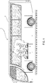
- Figure 1 illustrates a vehicle 1 for the public transport of passengers comprising a plurality of walls 2 connected to each other to define an internal volume 3 within which passengers of the vehicle 1 can be accommodated.
- This internal volume 3 is equipped with several supports for passengers such as seats 4.
- these seats 4 are arranged next to each other in rows 5 spaced apart at a predetermined distance from each other which allows the passenger to enter the respective row 5 and sit on the selected seat 4.
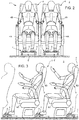
- Each seat 4 essentially comprises a support 4A and a column 4B configured to connect the support 4A to the floor of the vehicle 1.
- this column 4B may comprise a single support element or, as in the case described, a pair of support elements.
- each seat 4 may be equipped with a footrest 6 configured to allow a passenger seated on the seat 4 to rest their feet in an ergonomic position.
- a footrest 6 is placed in front of each seat 4 and may be attached to the floor of the vehicle 1 or to the seat 4 of the row 5 in front of the one where the passenger is sitting.
- the footrest 6 is borne by the preceding seat 4, in particular attached to its column 4B.
- the vehicle 1 comprises a health system 7 for each seat 4 configured to allow movement of the legs of a passenger seated in a seat 4, in the space between two rows 5.
- said health system 7 comprises an inflatable element 8 configured to dilate under the action of pressurized air so as to be deformable by the passenger under the action of a force imparted by the passenger's feet on the inflatable element 8.
- said health system 7 is integrated into the footrest 6 and is beneficially housed on its upper surface, i.e. the support surface for the passenger's feet.
- the inflatable element 8 essentially comprises an element of elastic material, for example rubber, of sufficient thickness to withstand the pressure imparted by the passenger's feet and to not be damaged as a result of contact with the passenger's shoes.
- This inflatable element 8 defines an enclosed space configured to selectively receive compressed air so as to inflate and deflate by occupying, or not occupying, a portion of space within the inside 3 of the vehicle 1.
- the health system 7 further comprises a pneumatic system 9 configured to selectively inflate and deflate the inflatable element 8.
- this pneumatic system 9 is thus configured to fluidly connect the inflatable element 8 to a source 10 of pressurized air such as a dedicated air pump or a compressed air reservoir shared with other systems of the vehicle 1.
- Figure 9 illustrates a first embodiment of the health system 7 according to the present invention wherein the inflatable element 8 comprises a single inflatable cushion 11 housed on the contact surface of the footrest 6 and connected to the pneumatic system by means of a duct 12.
- the pneumatic system 9 beneficially comprises valve means 13 configured to regulate fluid communication between the source 10 and the external environment so as to allow inflation and deflation of the cushion 11.
- said valve means 13 may essentially comprise a pressure relief valve 14 in fluid series with a control valve 15, beneficially a three-way two-position valve, configured to define a first position wherein it allows fluid communication between the source 10 of pressurized air and the cushion 11 and a second position wherein it allows fluid communication between the cushion 11 and the environment.
- Figure 10 illustrates a second embodiment of the health system 7 according to the present invention wherein the inflatable element 8 comprises a pair of inflatable cushions 11a, 11b fluidly separated from each other and connected by respective ducts 12a, 12b to the pneumatic system 9.
- the inflatable element 8 comprises a pair of inflatable cushions 11a, 11b fluidly separated from each other and connected by respective ducts 12a, 12b to the pneumatic system 9.
- the two inflatable cushions 11a, 11b are beneficially accommodated on the contact surface of the footrest 6 at two laterally opposite ends thereof, i.e. on the right and left sides of the footrest 6.
- the pneumatic system 9 beneficially comprises valve means 13 configured to regulate fluid communication between the source 10 and the external environment so as to allow independent inflation and deflation of each of the cushions 11a, 11b.
- valve means 13 may essentially comprise a relief valve 14 fluidly in series with a control valve 15, connected together as described above.
- the pneumatic system 9 further comprises pressure balancing means 16 to allow controlled fluid communication between the ducts 12a, 12b.
- Said pressure balancing means 16 essentially comprise non-return valves 17 respectively fluidly interposed in the ducts 12a, 12b between the cushions 11a, 11b and the pressure relief valve 14 as well as an equalizing valve 18 fluidly interposed in parallel between each duct 12a, 12b, between the cushions 11a, 11b and each non-return valve 17.
- control valve 15 is a four-way two-position valve, configured to define a first position in which it allows fluid communication between the source 10 of pressurized air and the cushion 11 via the pressure relief valve 14 and a second position wherein it allows direct fluid communication between the cushion 11a, 11b and the environment.
- the health system 7 may also comprise a control device (not shown) configured to control the operation of the pneumatic system 9, i.e. the actuation of the valves described below.
- This control device may be a remote control, a button, or an application that may be installed on a device in the vehicle 1 or on a passenger's smartphone.
- the operation of the health system 7 according to the present invention is as follows.
- the user when the user wishes to activate the health system 7, the user can activate the health system 7 using the control device.
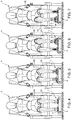
- the passenger allows the inflatable element 8 to be inflated so that the user can "walk” on it, as shown in Figures 4 to 8 , alternately with their right and left leg. In this way, it is possible to move the legs by simulating a kind of "walk", activating the muscles that may facilitate venous return.
- the user can deactivate the health system 7 allowing it to deflate and the inflatable element 8 returns to its position on the surface where it is housed, on the footrest 6 in the case described.
- control device controls the valve means 13 so as to allow the injection of air into the inflatable element 8, allowing air to pass from the source 10 to the pressure relief valve 14 via the control valve 15.
- the control valve 15 is therefore commanded to fluidly connect the inflatable element 8 with the environment.
- the operation of the pneumatic system 9 is the same as in the embodiment of Figure 9 described above except for the presence of the pressure balancing means 16.
- the non-return valves 17 allow passage of air solely in the fluid direction from the source 10 towards the cushions 11a, 11b.
- the control valve 15 prevents direct connection to the environment, the non-return valves 17 do not allow air to flow back towards the valve 15.
- fluid communication is allowed between the cushions 11a, 11b, damped by the valve 18, so that it is possible to allow the passage of air between one cushion 11a, 11b and the other depending on the action of passengers on the cushions.
- the health system 7 it is possible to provide a system that allows movement of the legs of the passengers sitting in the seats 4.
- the footrest 6 is particularly versatile since it can be used both as a known footrest, but also as a solution to improve blood circulation.
- the health system 7 may be attached to the footrest 6 or equally to the floor of the vehicle 1.
- pneumatic system 9 may be of any type and comprise other elements than those described.
- the inflatable element 8 may comprise more inflatable cushions 11, of different shapes and materials to those described.
Landscapes
- Engineering & Computer Science (AREA)
- Transportation (AREA)
- Mechanical Engineering (AREA)
- Seats For Vehicles (AREA)
- Vehicle Waterproofing, Decoration, And Sanitation Devices (AREA)
- Devices For Checking Fares Or Tickets At Control Points (AREA)
Abstract
Description
- This patent application claims priority from Italian patent application no.
102020000014359 filed on June 16, 2020 - The present invention relates to a vehicle, in particular a health system for a road vehicle intended for the public transport of passengers.
- Vehicles for the public transport of passengers, such as wheeled vehicles, for example coaches, are often used by passengers for long journeys that involve many hours of travel.
- During these long journeys, passengers sit continuously in their seats in a fixed position. This position is particularly uncomfortable for tall people. In addition, this fixed position increases the risk of phlebitis and embolism, especially for the elderly.
- Indeed, it is known that keeping the legs in a sitting position for too long damages the circulatory system by increasing the pressure in the venous return flow in the legs, normally helped by muscular movement of the legs.
- One solution to this problem could be to provide ample space in the vehicle for passengers to move around while the vehicle is in motion. However, this movement is obviously dangerous if the vehicle brakes suddenly. In fact, in some countries, it is forbidden to have standing passengers during journeys on tourist coaches.
- In addition, these large spaces would take away space for seats, reducing the number of passengers that could normally be carried.
- Therefore, there is a need to improve the health of seated passengers in the confined spaces of public passenger transport vehicles, such as coaches.
- This invention aims to solve the above-mentioned drawbacks in a simple and economical way.
- The above-mentioned objectives are achieved by a road vehicle for the public transport of passengers comprising a health system according to the attached claims.
- Other characteristics and benefits of the invention will become apparent from the following non-limiting description, provided for illustrative purposes, with reference to the attached drawings wherein:
-
Figure 1 is a schematic lateral view of a public passenger transport vehicle comprising a health system according to the present invention; -
Figure 2 is a schematic front view of an internal portion of the vehicle ofFigure 1 ; -
Figure 3 is a schematic lateral view of an internal portion of the vehicle ofFigure 1 ; -
Figures 4 to 7 are respective schematic front views of an internal portion of the vehicle ofFigure 1 in different operating conditions of the health system according to the present invention; -
Figure 8 is a schematic lateral view of an internal portion of the vehicle ofFigure 1 depicting an operating condition of the health system according to the present invention; and -
Figures 9 and 10 depict two different embodiments of the health system of the present invention. -
Figure 1 illustrates avehicle 1 for the public transport of passengers comprising a plurality ofwalls 2 connected to each other to define aninternal volume 3 within which passengers of thevehicle 1 can be accommodated. Thisinternal volume 3 is equipped with several supports for passengers such asseats 4. - As known, these
seats 4 are arranged next to each other inrows 5 spaced apart at a predetermined distance from each other which allows the passenger to enter therespective row 5 and sit on the selectedseat 4. - Each
seat 4 essentially comprises asupport 4A and acolumn 4B configured to connect thesupport 4A to the floor of thevehicle 1. Beneficially, thiscolumn 4B may comprise a single support element or, as in the case described, a pair of support elements. - Preferably, each
seat 4 may be equipped with afootrest 6 configured to allow a passenger seated on theseat 4 to rest their feet in an ergonomic position. As known, afootrest 6 is placed in front of eachseat 4 and may be attached to the floor of thevehicle 1 or to theseat 4 of therow 5 in front of the one where the passenger is sitting. In the example described, thefootrest 6 is borne by the precedingseat 4, in particular attached to itscolumn 4B. - According to the invention, the
vehicle 1 comprises ahealth system 7 for eachseat 4 configured to allow movement of the legs of a passenger seated in aseat 4, in the space between tworows 5. - In particular, said
health system 7 comprises aninflatable element 8 configured to dilate under the action of pressurized air so as to be deformable by the passenger under the action of a force imparted by the passenger's feet on theinflatable element 8. - Beneficially, said
health system 7 is integrated into thefootrest 6 and is beneficially housed on its upper surface, i.e. the support surface for the passenger's feet. - The
inflatable element 8 essentially comprises an element of elastic material, for example rubber, of sufficient thickness to withstand the pressure imparted by the passenger's feet and to not be damaged as a result of contact with the passenger's shoes. Thisinflatable element 8 defines an enclosed space configured to selectively receive compressed air so as to inflate and deflate by occupying, or not occupying, a portion of space within theinside 3 of thevehicle 1. - The
health system 7 further comprises apneumatic system 9 configured to selectively inflate and deflate theinflatable element 8. Beneficially, thispneumatic system 9 is thus configured to fluidly connect theinflatable element 8 to asource 10 of pressurized air such as a dedicated air pump or a compressed air reservoir shared with other systems of thevehicle 1. -
Figure 9 illustrates a first embodiment of thehealth system 7 according to the present invention wherein theinflatable element 8 comprises a singleinflatable cushion 11 housed on the contact surface of thefootrest 6 and connected to the pneumatic system by means of aduct 12. - In this embodiment, the
pneumatic system 9 beneficially comprises valve means 13 configured to regulate fluid communication between thesource 10 and the external environment so as to allow inflation and deflation of thecushion 11. - Beneficially, said valve means 13 may essentially comprise a
pressure relief valve 14 in fluid series with acontrol valve 15, beneficially a three-way two-position valve, configured to define a first position wherein it allows fluid communication between thesource 10 of pressurized air and thecushion 11 and a second position wherein it allows fluid communication between thecushion 11 and the environment. -
Figure 10 illustrates a second embodiment of thehealth system 7 according to the present invention wherein theinflatable element 8 comprises a pair ofinflatable cushions respective ducts pneumatic system 9. - The two
inflatable cushions footrest 6 at two laterally opposite ends thereof, i.e. on the right and left sides of thefootrest 6. - In this embodiment, the
pneumatic system 9 beneficially comprises valve means 13 configured to regulate fluid communication between thesource 10 and the external environment so as to allow independent inflation and deflation of each of thecushions - Beneficially, these valve means 13 may essentially comprise a
relief valve 14 fluidly in series with acontrol valve 15, connected together as described above. Furthermore, in this embodiment, thepneumatic system 9 further comprises pressure balancing means 16 to allow controlled fluid communication between theducts - Said pressure balancing means 16 essentially comprise
non-return valves 17 respectively fluidly interposed in theducts cushions pressure relief valve 14 as well as an equalizingvalve 18 fluidly interposed in parallel between eachduct cushions non-return valve 17. - In this case the
control valve 15 is a four-way two-position valve, configured to define a first position in which it allows fluid communication between thesource 10 of pressurized air and thecushion 11 via thepressure relief valve 14 and a second position wherein it allows direct fluid communication between thecushion - The
health system 7 may also comprise a control device (not shown) configured to control the operation of thepneumatic system 9, i.e. the actuation of the valves described below. This control device may be a remote control, a button, or an application that may be installed on a device in thevehicle 1 or on a passenger's smartphone. - The operation of the
health system 7 according to the present invention is as follows. - In general, when the user wishes to activate the
health system 7, the user can activate thehealth system 7 using the control device. Thus, the passenger allows theinflatable element 8 to be inflated so that the user can "walk" on it, as shown inFigures 4 to 8 , alternately with their right and left leg. In this way, it is possible to move the legs by simulating a kind of "walk", activating the muscles that may facilitate venous return. - When the user wishes, the user can deactivate the
health system 7 allowing it to deflate and theinflatable element 8 returns to its position on the surface where it is housed, on thefootrest 6 in the case described. - In the embodiment shown in
Figure 9 , the control device controls the valve means 13 so as to allow the injection of air into theinflatable element 8, allowing air to pass from thesource 10 to thepressure relief valve 14 via thecontrol valve 15. When theinflatable element 8 is to be deflated, thecontrol valve 15 is therefore commanded to fluidly connect theinflatable element 8 with the environment. - In the embodiment of
Figure 10 , the operation of thepneumatic system 9 is the same as in the embodiment ofFigure 9 described above except for the presence of the pressure balancing means 16. In effect, thenon-return valves 17 allow passage of air solely in the fluid direction from thesource 10 towards thecushions control valve 15 prevents direct connection to the environment, thenon-return valves 17 do not allow air to flow back towards thevalve 15. In this case, fluid communication is allowed between thecushions valve 18, so that it is possible to allow the passage of air between onecushion - From the foregoing, the benefits of a road vehicle comprising a health system according to the present invention are apparent.
- Thanks to the
health system 7, it is possible to provide a system that allows movement of the legs of the passengers sitting in theseats 4. - In particular, integration of the former in the
footrest 6, and its activation on a passenger's command, renders it particularly compact, not taking up any additional space between therows 5 of thevehicle 1. - In addition, it makes the
footrest 6 particularly versatile since it can be used both as a known footrest, but also as a solution to improve blood circulation. - Furthermore, the possibility of providing a single inflatable element comprising one or more inflatable elements allows for different types of
health systems 7 to be installed depending on the size and type ofvehicle 1. - Finally, it is apparent that the road vehicle comprising a health system according to the present invention may be subject to modifications and variations without thereby departing from the protective scope of the claims.
- In particular, as mentioned, the
health system 7 may be attached to thefootrest 6 or equally to the floor of thevehicle 1. - Furthermore, it is clear that the
pneumatic system 9 may be of any type and comprise other elements than those described. - In addition, the
inflatable element 8 may comprise moreinflatable cushions 11, of different shapes and materials to those described.
Claims (10)
- A road vehicle (1) comprising a plurality of walls (2) which delimit an interior space (3) suitable for transporting passengers, said vehicle (1) comprising a plurality of seats (4) configured to define a support (4A) suitable to accommodate a passenger of said vehicle (1), said vehicle (1) comprising a health system (7) for each seat (4), said health system (7) being fixed to said vehicle (1) in front of the respective seat (4) and comprising an inflatable element (8) configured to adopt a first configuration wherein it does not occupy space on the inside (3) of said vehicle (1) and a second configuration wherein it is inflated to occupy a space on the inside (3) of said vehicle (1), said inflatable element (8) being able to be compressed by said passenger when they are in said second configuration so as to allow movement of their legs.
- The vehicle (1) according to claim 1, wherein said inflatable element (8) is fixed to a floor of said vehicle (1) .
- The vehicle according to claim 1 comprising a footrest (6) fixed to said vehicle (1) and placed in front of said seat (4), said inflatable element (8) being fixed to an upper contact part of said footrest (6).
- The vehicle according to one of the preceding claims, comprising a pneumatic system (9) configured to introduce compressed air into said inflatable element (8) or to allow the escape of said compressed air from said inflatable element (8).
- The vehicle according to claim 4, wherein said pneumatic system (9) comprises a source (10) of pressurized fluid and valve means (13) fluidly interposed between said source (10) and said inflatable element (8) configured to regulate its inflation and deflation.
- The vehicle according to one of the preceding claims, wherein said inflatable element (8) comprises a single cushion (11).
- The vehicle according to one of the preceding claims, wherein said inflatable element (8) comprises at least two cushions (11a, 11b).
- The vehicle according to one of the preceding claims, wherein said inflatable element (8) is made of elastic material so as to adhere to the respective support when it is in the first configuration.
- The vehicle according to claim 7, wherein said pneumatic system (9) further comprises balancing means (16) fluidly interposed between said at least two cushions (11a, 11b) to allow fluid communication between them.
- The vehicle according to one of the preceding claims, comprising a control device configured to control the passage of compressed air in said inflatable element to allow passage between the first and the second configuration.
Applications Claiming Priority (1)
| Application Number | Priority Date | Filing Date | Title |
|---|---|---|---|
| IT102020000014359A IT202000014359A1 (en) | 2020-06-16 | 2020-06-16 | VEHICLE FOR PUBLIC TRANSPORT INCLUDING A SANITARY SYSTEM FOR PASSENGERS |
Publications (3)
| Publication Number | Publication Date |
|---|---|
| EP3925825A1 true EP3925825A1 (en) | 2021-12-22 |
| EP3925825C0 EP3925825C0 (en) | 2025-11-26 |
| EP3925825B1 EP3925825B1 (en) | 2025-11-26 |
Family
ID=72473670
Family Applications (1)
| Application Number | Title | Priority Date | Filing Date |
|---|---|---|---|
| EP21305820.9A Active EP3925825B1 (en) | 2020-06-16 | 2021-06-16 | Vehicle for public transport comprising a health system for passengers |
Country Status (2)
| Country | Link |
|---|---|
| EP (1) | EP3925825B1 (en) |
| IT (1) | IT202000014359A1 (en) |
Citations (5)
| Publication number | Priority date | Publication date | Assignee | Title |
|---|---|---|---|---|
| US3860284A (en) * | 1973-03-02 | 1975-01-14 | Sanford Lichtig | Safety device for automobiles |
| US4955658A (en) * | 1989-08-28 | 1990-09-11 | Wickes Manufacturing Company | Automobile foot rest |
| CN104057860A (en) * | 2013-03-22 | 2014-09-24 | 大众汽车有限公司 | Foot Placing Part And Vehicle With Same |
| DE102014222352A1 (en) * | 2014-11-03 | 2016-05-04 | Ford Global Technologies, Llc | Footrest for a motor vehicle |
| DE102017223085A1 (en) * | 2017-12-18 | 2019-06-19 | Bayerische Motoren Werke Aktiengesellschaft | motor vehicle |
-
2020
- 2020-06-16 IT IT102020000014359A patent/IT202000014359A1/en unknown
-
2021
- 2021-06-16 EP EP21305820.9A patent/EP3925825B1/en active Active
Patent Citations (5)
| Publication number | Priority date | Publication date | Assignee | Title |
|---|---|---|---|---|
| US3860284A (en) * | 1973-03-02 | 1975-01-14 | Sanford Lichtig | Safety device for automobiles |
| US4955658A (en) * | 1989-08-28 | 1990-09-11 | Wickes Manufacturing Company | Automobile foot rest |
| CN104057860A (en) * | 2013-03-22 | 2014-09-24 | 大众汽车有限公司 | Foot Placing Part And Vehicle With Same |
| DE102014222352A1 (en) * | 2014-11-03 | 2016-05-04 | Ford Global Technologies, Llc | Footrest for a motor vehicle |
| DE102017223085A1 (en) * | 2017-12-18 | 2019-06-19 | Bayerische Motoren Werke Aktiengesellschaft | motor vehicle |
Also Published As
| Publication number | Publication date |
|---|---|
| IT202000014359A1 (en) | 2021-12-16 |
| EP3925825C0 (en) | 2025-11-26 |
| EP3925825B1 (en) | 2025-11-26 |
Similar Documents
| Publication | Publication Date | Title |
|---|---|---|
| CN105857135B (en) | Vehicle seat with muscle massage system | |
| US4592588A (en) | Vehicle seat | |
| US5678891A (en) | Dynamic combination seating and backrest support system | |
| US9840171B2 (en) | Adjustable firmness vehicle seat | |
| US4698864A (en) | Cellular cushion | |
| US4890885A (en) | Seat for a vehicle, aircraft or the like | |
| US9802521B2 (en) | Multilayer seat | |
| US3326601A (en) | Inflatable back support for a seat | |
| EP1447070A1 (en) | Seat with massaging apparatus and process for performing a massage | |
| US6074006A (en) | Automotive seat with pneumatic pelvic stabilization | |
| US11612539B2 (en) | Chair-type massager | |
| US20170079872A1 (en) | Adjustable seat assembly | |
| US20090188045A1 (en) | Under-thigh support | |
| EP4234199A3 (en) | Seating apparatus | |
| CN110127060A (en) | Using the passenger seat of the pneumatic seat cushion of radial type | |
| JP2018095015A (en) | Vehicle seat | |
| US20070056112A1 (en) | Zoned cellular cushion with fail safe inflation zones | |
| US7455355B1 (en) | User adjustable motorcycle seat cushion with independently inflatable and deflatable ischial support cell and gluteous support cell | |
| EP3925825B1 (en) | Vehicle for public transport comprising a health system for passengers | |
| EP3526076B1 (en) | Adjustable seat | |
| US12337738B2 (en) | Fluid system for a vehicle seat assembly | |
| US20250153620A1 (en) | Fluid system for a vehicle seat assembly | |
| JPH0246203B2 (en) | ||
| US10004336B2 (en) | Method and apparatus for supporting normal functions of blood circulatory systems over long periods of sitting | |
| RU2620144C1 (en) | Adaptive transport seat of higher safety |
Legal Events
| Date | Code | Title | Description |
|---|---|---|---|
| PUAI | Public reference made under article 153(3) epc to a published international application that has entered the european phase |
Free format text: ORIGINAL CODE: 0009012 |
|
| STAA | Information on the status of an ep patent application or granted ep patent |
Free format text: STATUS: THE APPLICATION HAS BEEN PUBLISHED |
|
| AK | Designated contracting states |
Kind code of ref document: A1 Designated state(s): AL AT BE BG CH CY CZ DE DK EE ES FI FR GB GR HR HU IE IS IT LI LT LU LV MC MK MT NL NO PL PT RO RS SE SI SK SM TR |
|
| B565 | Issuance of search results under rule 164(2) epc |
Effective date: 20211110 |
|
| STAA | Information on the status of an ep patent application or granted ep patent |
Free format text: STATUS: REQUEST FOR EXAMINATION WAS MADE |
|
| 17P | Request for examination filed |
Effective date: 20220613 |
|
| RBV | Designated contracting states (corrected) |
Designated state(s): AL AT BE BG CH CY CZ DE DK EE ES FI FR GB GR HR HU IE IS IT LI LT LU LV MC MK MT NL NO PL PT RO RS SE SI SK SM TR |
|
| STAA | Information on the status of an ep patent application or granted ep patent |
Free format text: STATUS: EXAMINATION IS IN PROGRESS |
|
| 17Q | First examination report despatched |
Effective date: 20231024 |
|
| GRAP | Despatch of communication of intention to grant a patent |
Free format text: ORIGINAL CODE: EPIDOSNIGR1 |
|
| STAA | Information on the status of an ep patent application or granted ep patent |
Free format text: STATUS: GRANT OF PATENT IS INTENDED |
|
| INTG | Intention to grant announced |
Effective date: 20250627 |
|
| RIN1 | Information on inventor provided before grant (corrected) |
Inventor name: CODRON, STEPHANE |
|
| GRAS | Grant fee paid |
Free format text: ORIGINAL CODE: EPIDOSNIGR3 |
|
| GRAA | (expected) grant |
Free format text: ORIGINAL CODE: 0009210 |
|
| STAA | Information on the status of an ep patent application or granted ep patent |
Free format text: STATUS: THE PATENT HAS BEEN GRANTED |
|
| AK | Designated contracting states |
Kind code of ref document: B1 Designated state(s): AL AT BE BG CH CY CZ DE DK EE ES FI FR GB GR HR HU IE IS IT LI LT LU LV MC MK MT NL NO PL PT RO RS SE SI SK SM TR |
|
| REG | Reference to a national code |
Ref country code: CH Ref legal event code: F10 Free format text: ST27 STATUS EVENT CODE: U-0-0-F10-F00 (AS PROVIDED BY THE NATIONAL OFFICE) Effective date: 20251126 Ref country code: GB Ref legal event code: FG4D |
|
| REG | Reference to a national code |
Ref country code: IE Ref legal event code: FG4D |
|
| U01 | Request for unitary effect filed |
Effective date: 20251128 |
|
| U07 | Unitary effect registered |
Designated state(s): AT BE BG DE DK EE FI FR IT LT LU LV MT NL PT RO SE SI Effective date: 20251204 |
|
| PG25 | Lapsed in a contracting state [announced via postgrant information from national office to epo] |
Ref country code: ES Free format text: LAPSE BECAUSE OF FAILURE TO SUBMIT A TRANSLATION OF THE DESCRIPTION OR TO PAY THE FEE WITHIN THE PRESCRIBED TIME-LIMIT Effective date: 20251126 |
|
| PG25 | Lapsed in a contracting state [announced via postgrant information from national office to epo] |
Ref country code: NO Free format text: LAPSE BECAUSE OF FAILURE TO SUBMIT A TRANSLATION OF THE DESCRIPTION OR TO PAY THE FEE WITHIN THE PRESCRIBED TIME-LIMIT Effective date: 20260226 |
|
| PG25 | Lapsed in a contracting state [announced via postgrant information from national office to epo] |
Ref country code: HR Free format text: LAPSE BECAUSE OF FAILURE TO SUBMIT A TRANSLATION OF THE DESCRIPTION OR TO PAY THE FEE WITHIN THE PRESCRIBED TIME-LIMIT Effective date: 20251126 |
|
| PG25 | Lapsed in a contracting state [announced via postgrant information from national office to epo] |
Ref country code: RS Free format text: LAPSE BECAUSE OF FAILURE TO SUBMIT A TRANSLATION OF THE DESCRIPTION OR TO PAY THE FEE WITHIN THE PRESCRIBED TIME-LIMIT Effective date: 20260226 |
|
| PG25 | Lapsed in a contracting state [announced via postgrant information from national office to epo] |
Ref country code: IS Free format text: LAPSE BECAUSE OF FAILURE TO SUBMIT A TRANSLATION OF THE DESCRIPTION OR TO PAY THE FEE WITHIN THE PRESCRIBED TIME-LIMIT Effective date: 20260326 |
|
| PG25 | Lapsed in a contracting state [announced via postgrant information from national office to epo] |
Ref country code: PL Free format text: LAPSE BECAUSE OF FAILURE TO SUBMIT A TRANSLATION OF THE DESCRIPTION OR TO PAY THE FEE WITHIN THE PRESCRIBED TIME-LIMIT Effective date: 20251126 |