EP3925794A1 - Pneumatic tire - Google Patents
Pneumatic tire Download PDFInfo
- Publication number
- EP3925794A1 EP3925794A1 EP21173846.3A EP21173846A EP3925794A1 EP 3925794 A1 EP3925794 A1 EP 3925794A1 EP 21173846 A EP21173846 A EP 21173846A EP 3925794 A1 EP3925794 A1 EP 3925794A1
- Authority
- EP
- European Patent Office
- Prior art keywords
- edge
- carcass
- carcass ply
- ply
- tire
- Prior art date
- Legal status (The legal status is an assumption and is not a legal conclusion. Google has not performed a legal analysis and makes no representation as to the accuracy of the status listed.)
- Granted
Links
Images


Classifications
-
- B—PERFORMING OPERATIONS; TRANSPORTING
- B60—VEHICLES IN GENERAL
- B60C—VEHICLE TYRES; TYRE INFLATION; TYRE CHANGING; CONNECTING VALVES TO INFLATABLE ELASTIC BODIES IN GENERAL; DEVICES OR ARRANGEMENTS RELATED TO TYRES
- B60C15/00—Tyre beads, e.g. ply turn-up or overlap
- B60C15/0009—Tyre beads, e.g. ply turn-up or overlap features of the carcass terminal portion
-
- B—PERFORMING OPERATIONS; TRANSPORTING
- B60—VEHICLES IN GENERAL
- B60C—VEHICLE TYRES; TYRE INFLATION; TYRE CHANGING; CONNECTING VALVES TO INFLATABLE ELASTIC BODIES IN GENERAL; DEVICES OR ARRANGEMENTS RELATED TO TYRES
- B60C9/00—Reinforcements or ply arrangement of pneumatic tyres
- B60C9/02—Carcasses
-
- B—PERFORMING OPERATIONS; TRANSPORTING
- B60—VEHICLES IN GENERAL
- B60C—VEHICLE TYRES; TYRE INFLATION; TYRE CHANGING; CONNECTING VALVES TO INFLATABLE ELASTIC BODIES IN GENERAL; DEVICES OR ARRANGEMENTS RELATED TO TYRES
- B60C15/00—Tyre beads, e.g. ply turn-up or overlap
- B60C15/0009—Tyre beads, e.g. ply turn-up or overlap features of the carcass terminal portion
- B60C15/0018—Tyre beads, e.g. ply turn-up or overlap features of the carcass terminal portion not folded around the bead core, e.g. floating or down ply
-
- B—PERFORMING OPERATIONS; TRANSPORTING
- B60—VEHICLES IN GENERAL
- B60C—VEHICLE TYRES; TYRE INFLATION; TYRE CHANGING; CONNECTING VALVES TO INFLATABLE ELASTIC BODIES IN GENERAL; DEVICES OR ARRANGEMENTS RELATED TO TYRES
- B60C15/00—Tyre beads, e.g. ply turn-up or overlap
- B60C15/0009—Tyre beads, e.g. ply turn-up or overlap features of the carcass terminal portion
- B60C15/0027—Tyre beads, e.g. ply turn-up or overlap features of the carcass terminal portion with low ply turn-up, i.e. folded around the bead core and terminating at the bead core
-
- B—PERFORMING OPERATIONS; TRANSPORTING
- B60—VEHICLES IN GENERAL
- B60C—VEHICLE TYRES; TYRE INFLATION; TYRE CHANGING; CONNECTING VALVES TO INFLATABLE ELASTIC BODIES IN GENERAL; DEVICES OR ARRANGEMENTS RELATED TO TYRES
- B60C15/00—Tyre beads, e.g. ply turn-up or overlap
- B60C15/0009—Tyre beads, e.g. ply turn-up or overlap features of the carcass terminal portion
- B60C15/0054—Tyre beads, e.g. ply turn-up or overlap features of the carcass terminal portion with ply turn-up portion parallel and adjacent to carcass main portion
-
- B—PERFORMING OPERATIONS; TRANSPORTING
- B60—VEHICLES IN GENERAL
- B60C—VEHICLE TYRES; TYRE INFLATION; TYRE CHANGING; CONNECTING VALVES TO INFLATABLE ELASTIC BODIES IN GENERAL; DEVICES OR ARRANGEMENTS RELATED TO TYRES
- B60C9/00—Reinforcements or ply arrangement of pneumatic tyres
- B60C9/02—Carcasses
- B60C9/17—Carcasses asymmetric to the midcircumferential plane of the tyre
-
- B—PERFORMING OPERATIONS; TRANSPORTING
- B60—VEHICLES IN GENERAL
- B60C—VEHICLE TYRES; TYRE INFLATION; TYRE CHANGING; CONNECTING VALVES TO INFLATABLE ELASTIC BODIES IN GENERAL; DEVICES OR ARRANGEMENTS RELATED TO TYRES
- B60C9/00—Reinforcements or ply arrangement of pneumatic tyres
- B60C9/18—Structure or arrangement of belts or breakers, crown-reinforcing or cushioning layers
- B60C9/20—Structure or arrangement of belts or breakers, crown-reinforcing or cushioning layers built-up from rubberised plies each having all cords arranged substantially parallel
-
- B—PERFORMING OPERATIONS; TRANSPORTING
- B60—VEHICLES IN GENERAL
- B60C—VEHICLE TYRES; TYRE INFLATION; TYRE CHANGING; CONNECTING VALVES TO INFLATABLE ELASTIC BODIES IN GENERAL; DEVICES OR ARRANGEMENTS RELATED TO TYRES
- B60C9/00—Reinforcements or ply arrangement of pneumatic tyres
- B60C9/02—Carcasses
- B60C2009/0269—Physical properties or dimensions of the carcass coating rubber
- B60C2009/0276—Modulus; Hardness; Loss modulus or "tangens delta"
-
- B—PERFORMING OPERATIONS; TRANSPORTING
- B60—VEHICLES IN GENERAL
- B60C—VEHICLE TYRES; TYRE INFLATION; TYRE CHANGING; CONNECTING VALVES TO INFLATABLE ELASTIC BODIES IN GENERAL; DEVICES OR ARRANGEMENTS RELATED TO TYRES
- B60C9/00—Reinforcements or ply arrangement of pneumatic tyres
- B60C9/02—Carcasses
- B60C9/04—Carcasses the reinforcing cords of each carcass ply arranged in a substantially parallel relationship
- B60C2009/0416—Physical properties or dimensions of the carcass cords
- B60C2009/0441—Density in width direction
-
- B—PERFORMING OPERATIONS; TRANSPORTING
- B60—VEHICLES IN GENERAL
- B60C—VEHICLE TYRES; TYRE INFLATION; TYRE CHANGING; CONNECTING VALVES TO INFLATABLE ELASTIC BODIES IN GENERAL; DEVICES OR ARRANGEMENTS RELATED TO TYRES
- B60C9/00—Reinforcements or ply arrangement of pneumatic tyres
- B60C9/02—Carcasses
- B60C9/04—Carcasses the reinforcing cords of each carcass ply arranged in a substantially parallel relationship
- B60C2009/0416—Physical properties or dimensions of the carcass cords
- B60C2009/045—Tensile strength
Definitions
- the tire may have improved cut resistance and durability.
- the first carcass ply is folded back radially outwardly in the first bead portion so as to have a folded-back portion having a first edge, and the first carcass ply has a second edge positioned in the second bead portion and radially inside the first edge.
- the carcass further comprises a third carcass ply which is, in the tread portion, located radially inside the first carcass ply and the second carcass ply.
- the fifth edge and the sixth edge are located radially outside the first edge.
- the carcass plies include the first carcass ply and the second carcass ply which have the same ply length, it is possible to use the same ply material for at least the first and second carcass plies, and as a result, the manufacturing cost can be reduced. Further, since the pneumatic tire has at least two carcass plies, the tire is provided with excellent cut resistance. In the pneumatic tire according to the present invention, since the first carcass ply and the second carcass ply are each arranged asymmetrically with respect to the equator of the tire, there is no possibility that the edges of the first carcass ply 7A respectively overlap with the edges of the second carcass ply 7B. Therefore, stress can be dispersed, and durability can be improved.
- the complex elastic modulus E* is measured in accordance Japanese Industrial Standard (JIS) K6394 under the following conditions, using a dynamic viscoelasticity measuring device.
- the first carcass ply 7A is not folded back in the second bead portion 4B. Since such first carcass ply 7A is further decreased in the weight, it is possible to further improve the fuel efficiency of the tire 1. However, it is also possible that the first carcass ply 7A is folded back in the second bead portion 4B so as to have a folded-back portion having the above-said second edge 7b located radially inside the first edge 7a.
- the tire 10 in the second embodiment comprises a tread portion 2, a pair of sidewall portions 3, and a pair of bead portions 4 including a second bead portion 4B and a second bead portion 4B, similarly to the tire 1 described above.
- the carcass plies 12 include a first carcass ply 12A and a second carcass ply 12B which have the same ply length.
- the second carcass ply 12B is arranged radially inside the first carcass ply 12A.
- the two carcass plies 12 since the two carcass plies 12 have the same ply length, these can be formed from the same ply materials, and the manufacturing cost can be reduced.
- the fifth edge 12e and the sixth edge 12f are located radially outside the first edge 12a and the third edge 12c.
- the first edge 12a, the second edge 12b, the third edge 12c, and the fourth edge 12d are covered with the third carcass ply 12c, therefore, it is possible to further improve the durability of the tire 10.
- the distance d3 in the tire radial direction between the first edge 12a and the fourth edge 12d is not less than 10 mm.
- the distance d4 in the tire radial direction between the first edge 12a and the fifth edge 12e is not less than 10 mm.
- the distance d3 and the distance d4 are more preferably not less than 15 mm, and further preferably not less than 20 mm.
- the distance d5 in the tire radial direction between the second edge 12b and the third edge 12c is not less than 10 mm.
- the distance d6 in the tire radial direction between the third edge 12c and the sixth edge 12f is not less than 10 mm.
- the distance d5 and the distance d6 are more preferably not less than 15 mm, and more preferably not less than 20 mm.
- the carcass plies 22 include a first carcass ply 22A and a second carcass ply 22B which have the same ply length.
- the second carcass ply 22B is, in the tread portion, arranged radially inside the first carcass ply 22A.
- the two carcass plies 22 have the same ply length, these can be formed from the same ply materials, and the manufacturing cost can be reduced.
- the second carcass ply 22B is folded back radially outwardly in the second bead portion 4B so as to have a folded-back portion having a third edge 22c, and the second carcass ply 22B has a fourth edge 22d located in the first bead portion 4A and radially inside the third edge 22c. Since the ply length of the second carcass ply 22B can be reduced, the weight can be reduced, and the fuel efficiency of the tire 20 can be improved.
- the second carcass ply 22B is not folded back in the first bead portion 4A. Since such second carcass ply 22B can be reduced in the weight, the fuel efficiency of the tire 20 can be further improved.
- first edge 22a and the third edge 22c are located at the same radial height. It is desirable that the second edge 22b and the fourth edge 22d are located at the same radial height.
- the tire having such carcass plies 22 has a good balance in the tire axial direction as a whole, and can improve the steering stability of the tire 20.
- the carcass having such carcass plies 22 has a good balance in the tire axial direction as a whole, and can improve the steering stability of the tire 20.
- the distance d7 in the tire radial direction between the first edge 22a and the fourth edge 22d is not less than 10 mm.
- the distance d8 in the tire radial direction between the first edge 22a and the fifth edge 22e is not less than 10 mm.
- the distance d7 and the distance d8 are more preferably not less than 15 mm, still more preferably not less than 20 mm.
- the weight of each test tire was measured.
- pneumatic tires were experimentally manufactured as working example 3 and working example 4. And a pneumatic tire as Comparative Example 3 having a carcass composed of three types of carcass plies having different ply lengths was experimentally manufactured. These test tires were tested for the cut resistance, durability and fuel efficiency as explained above. Specifications of these test tires and test results are shown in Table 2.
Landscapes
- Engineering & Computer Science (AREA)
- Mechanical Engineering (AREA)
- Tires In General (AREA)
Abstract
Description
- The present invention relates to a pneumatic tire with a carcass.
- Conventionally, a pneumatic tire having a carcass composed of a plurality of carcass plies is known. The following Patent Document 1 discloses a pneumatic tire provided with a first carcass ply, and a second carcass ply disposed on the outer side of the first carcass ply, wherein turned-up portions of the first carcass ply are made higher than turned-up portions of the second carcass ply.
Patent Document 1:Japanese Patent Application Publication No. 2019-11205 - In the pneumatic tire according to Patent Document 1, owing to the turned-up portions of the two carcass plies having different heights, the tire may have improved cut resistance and durability. However, in the pneumatic tire according to Patent Document 1, it is necessary to prepare two types of carcass ply materials for the first carcass ply and second carcass ply, having different ply/material lengths in order to form the carcass. This increases the tire manufacturing cost including the management cost of the material.
- The present invention was made in view of the above circumstances, and a primary objective of the present invention is to provide a pneumatic tire capable of reducing manufacturing costs while maintaining good cut resistance and durability.
- According to the present invention, a pneumatic tire comprises: a tread portion, a pair of sidewall portions, a pair of axially spaced first and second bead portions, and a carcass extending between the first and second bead portions through the tread portion and the sidewall portions, wherein
the carcass is composed of a plurality of carcass plies including a first carcass ply having a ply length, and a second carcass ply having a ply length which is the same as the ply length of the first carcass ply, and
each of the first carcass ply and the second carcass ply is arranged asymmetrically with respect to a tire equator. - It is desirable that the first carcass ply is folded back radially outwardly in the first bead portion so as to have a folded-back portion having a first edge, and the first carcass ply has a second edge positioned in the second bead portion and radially inside the first edge.
- The first carcass ply may be not folded back in the second bead portion.
- The first carcass ply may be folded back in the second bead portion so as to have a folded-back portion having the above-said second edge which is positioned radially inside the first edge.
- It is desirable that the second carcass ply is folded back radially outwardly in the second bead portion so as to have a folded-back portion having a third edge, and
the second carcass ply has a fourth edge positioned in the first bead portion and radially inside the third edge. - It is desirable that a distance in the tire radial direction between the first edge and the fourth edge is not less than 10 mm.
- It is desirable that the carcass further comprises a third carcass ply which is, in the tread portion, located radially inside the first carcass ply and the second carcass ply.
- It is desirable that the third carcass ply is folded back radially outwardly in the first bead portion so as to have a folded-back portion having a fifth edge, and
the third carcass ply is folded back radially outwardly in the second bead portion so as to have a folded-back portion having a sixth edge. - It is desirable that the fifth edge and the sixth edge are located at the same radial height.
- It is desirable that the fifth edge and the sixth edge are located radially outside the first edge.
- Each of the carcass plies is composed of carcass cords rubberized with a topping rubber, wherein
the carcass cords each have a cord strength F (N),
the carcass cords are arranged side by side with a cord count N per 5 cm,
the topping rubber has a complex elastic modulus E* (MPa) at 70 degrees C, and
each of the carcass plies has a carcass ply strength defined by a product (F x N x E*), and
in a boundary portion between the tread portion and each sidewall portion, the sum of the carcass ply strengths of all the carcass plies is preferably not less than 200,000. - In the pneumatic tire according to the present invention, since the carcass plies include the first carcass ply and the second carcass ply which have the same ply length, it is possible to use the same ply material for at least the first and second carcass plies, and as a result, the manufacturing cost can be reduced. Further, since the pneumatic tire has at least two carcass plies, the tire is provided with excellent cut resistance.
In the pneumatic tire according to the present invention, since the first carcass ply and the second carcass ply are each arranged asymmetrically with respect to the equator of the tire, there is no possibility that the edges of thefirst carcass ply 7A respectively overlap with the edges of thesecond carcass ply 7B. Therefore, stress can be dispersed, and durability can be improved. - Thus, the pneumatic tire according to the present invention can be reduced in the manufacturing cost while maintaining good cut resistance and durability.
-
-
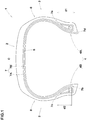
Fig. 1 is a schematic cross-sectional view of a pneumatic tire as a first embodiment of the present invention. -
Fig. 2 is a schematic cross-sectional view of a pneumatic tire as a second embodiment of the present invention. -
Fig. 3 is a schematic cross-sectional view of a pneumatic tire as a third embodiment of the present invention. - Hereinafter, embodiments of the present invention will be described in detail with reference to the drawings.
-
Fig. 1 is a schematic cross-sectional view including a tire rotational axis (not shown), of a pneumatic tire 1 as an embodiment of the present invention. - As shown in
Fig. 1 , the tire 1 has atread portion 2 which comes into contact with the ground, a pair of axially spacedbead portions 4, and a pair ofsidewall portions 3 extending from tread edges of thetread portion 2 to thebead portions 4. Thebead portions 4 include afirst bead portion 4A and asecond bead portion 4B. - The tire 1 is provided with a
carcass 6 extending between thefirst bead portion 4A and thesecond bead portion 4B through thetread portion 2 and thesidewall portions 3. In order to reinforce the tread portion, thetread portion 2 may be provided with, for example, a belt (not shown) arranged radially outside thecarcass 6 and a band (not shown) arranged radially outside the belt. - In the present embodiment, the
carcass 6 is composed of at least twocarcass plies 7. Since eachsidewall portion 3 of such tire 1 is reinforced by the at least twocarcass plies 7, the tire is provided with excellent cut resistance in thesidewall portions 3. - The carcass plies 7 in the present embodiment include a
first carcass ply 7A and asecond carcass ply 7B having the same ply length. - Here, the ply length of a carcass ply means the length measured from one of edges thereof to the other of the edges along the carcass ply in a cross section of the tire as shown in
Figs. 1-3 . - when considered in the tread portion, the
second carcass ply 7B is arranged radially inside thefirst carcass ply 7A. In such tire 1, since the at least two carcass plies have the same ply length,
these can be formed from the same ply materials, and the manufacturing cost can be reduced. - Each of the
first carcass ply 7A and thesecond carcass ply 7B of the present embodiment is arranged asymmetrically with respect to the tire equator C. Therefore, there is no possibility that the edges of thefirst carcass ply 7A respectively overlap with the edges of thesecond carcass ply 7B. Thus, stress can be dispersed, and durability can be improved. Therefore, the tire 1 of the present embodiment can be reduced in the manufacturing cost while maintaining good cut resistance and durability. - Incidentally, the tire equator C is the central position in the tire axial direction, of the ground contacting patch when the tire in a normal state contacts a flat plane at a camber angle of zero under a normal tire load.
- Here, the "normal state" is a state in which the tire is mounted on a normal rim and inflated to a normal pressure without tire load.
- The normal rim is a wheel rim officially approved or recommended for the tire by standards organizations, i.e. JATMA (Japan and Asia), T&RA (North America), ETRTO (Europe), TRAA (Australia), STRO (Scandinavia), ALAPA (Latin America), ITTAC (India) and the like which are effective in the area where the tire is manufactured, sold or used.
The normal pressure and the normal tire load are the maximum air pressure and the maximum tire load for the tire specified by the same organization in the Air-pressure/Maximum-load Table or similar list.
For example, the normal rim is the "standard rim" specified in JATMA, the "Measuring Rim" in ETRTO, the "Design Rim" in TRA or the like. The normal tire pressure is the "maximum air pressure" in JATMA, the "Inflation Pressure" in ETRTO, the maximum pressure given in the "Tire Load Limits at various cold Inflation Pressures" table in TRA or the like. The normal tire load is the "maximum load capacity" in JATMA, the "Load Capacity" in ETRTO, the maximum value given in the above-mentioned table in TRA or the like.
As to the normal rim, normal tire pressure and normal tire load, if there is no standard to be applied to the tire in the standards organization, those specified by the tire manufacturer should be adopted. - Each carcass ply 7 is composed of carcass cords (not shown) rubberized with a topping rubber (not shown).
- It is preferable that, in a buttress
portion 8 which is a boundary portion between thetread portion 2 and eachsidewall portion 3, thecarcass 6 has a carcass strength of not less than 200000, preferably not less than 250000, more preferably not less than 300000, wherein
the carcass strength is the sum of ply strengths of all the carcass plies 7 constituting the carcass, and
the ply strength of each carcass ply is a product (F x N x E) of a cord strength F (N) of a carcass cord, a cord count N of the carcass cords per 5 cm, and a complex elastic modulus E* (MPa) of the topping rubber at 70 degrees C. - By setting the carcass strength 200000 or more, cut resistance sufficient for running on rough roads can be provided.
- Here, the complex elastic modulus E* is measured in accordance Japanese Industrial Standard (JIS) K6394 under the following conditions, using a dynamic viscoelasticity measuring device.
- Initial strain: 10%
- Amplitude: +/-1%
- Frequency: 10HZ
- Measuring mode: tensile deformation
- Measurement temperature: 70 degrees C
- In the present embodiment, the
first carcass ply 7A is folded back radially outwardly in thefirst bead portion 4A so as to have a folded-back portion having afirst edge 7a, and thefirst carcass ply 7A has asecond edge 7b located in thesecond bead portion 4B and radially inside thefirst edge 7a. Since thefirst carcass ply 7A can be decreased in the ply length, the weight can be reduced, and the fuel efficiency performance of the tire 1 can be improved. - In the present embodiment, the
first carcass ply 7A is not folded back in thesecond bead portion 4B. Since suchfirst carcass ply 7A is further decreased in the weight, it is possible to further improve the fuel efficiency of the tire 1. However, it is also possible that thefirst carcass ply 7A is folded back in thesecond bead portion 4B so as to have a folded-back portion having the above-saidsecond edge 7b located radially inside thefirst edge 7a. - In the present embodiment, the
second carcass ply 7B is folded back in thesecond bead portion 4B so as to have a folded-back portion having athird edge 7c, and the second carcass ply 7B has afourth edge 7d located in thefirst bead portion 4A and radially inside thethird edge 7c. Since thesecond carcass ply 7B can be decreased in the ply length, the weight can be reduced, and the fuel efficiency of the tire 1 can be improved. - In the present embodiment, the
second carcass ply 7B is not folded back in thefirst bead portion 4A. Since suchsecond carcass ply 7B can be decreased in the weight, the fuel efficiency of the tire 1 can be further improved. However, it is also possible that thesecond carcass ply 7B is folded back in thefirst bead portion 4A so as to have a folded-back portion having the above-saidfourth edge 7d located radially inside thethird edge 7c. - The
first edge 7a and thethird edge 7c may be located at the same radial height. In this case, it is desirable that thesecond edge 7b and thefourth edge 7d are located at the same radial height.
The carcass having such carcass plies 7 has a good balance in the tire axial direction and can improve the steering stability of the tire 1. - Preferably, the distance d1 in the tire radial direction between the
first edge 7a and thefourth edge 7d is not less than 10 mm. when the distance d1 is not less than 10 mm, the stress at thefirst edge 7a and the stress at thefourth edge 7d can be dispersed, and thereby the durability of the tire 1 can be improved.
From this point of view, the distance d1 is more preferably not less than 15 mm, still more preferably not less than 20 mm. - Preferably, the distance d2 in the tire radial direction between the
second edge 7b and thethird edge 7c is not less than 10 mm. when the distance d2 is not less than 10 mm, the stress at thesecond edge 7b and the stress at thethird edge 7c can be dispersed, and thereby the durability of the tire 1 can be improved.
From this point of view, the distance d2 is more preferably not less than 15 mm, still more preferably not less than 20 mm. -
Fig. 2 is a schematic cross-sectional view including a tire rotational axis (not shown), of apneumatic tire 10 as a second embodiment of the present invention.
Elements or components having the same functions as those in the above-described first embodiment are designated by the same reference numerals, and the description thereof will be omitted. - As shown in
Fig. 2 , thetire 10 in the second embodiment comprises atread portion 2, a pair ofsidewall portions 3, and a pair ofbead portions 4 including asecond bead portion 4B and asecond bead portion 4B, similarly to the tire 1 described above. - The
tire 10 is provided with acarcass 11 extending between thefirst bead portion 4A and thesecond bead portion 4B through thetread portion 2 and thesidewall portions 3. Similar to the tire 1 described above, thetread portion 2 of thetire 10 may be provided with a belt (not shown) disposed radially outside thecarcass 11, and a band (not shown) disposed radially outside the belt. - The
carcass 11 of the second embodiment is composed of three carcass plies 12. Since eachsidewall portion 3 ofsuch tire 10 is reinforced by the at least threecarcass plies 7, thesidewall portions 3 can be provided with excellent cut resistance. - In the second embodiment, the carcass plies 12 include a first carcass ply 12A and a
second carcass ply 12B which have the same ply length. when considered in the tread portion, thesecond carcass ply 12B is arranged radially inside the first carcass ply 12A. Insuch tire 10, since the two carcass plies 12 have the same ply length, these can be formed from the same ply materials, and the manufacturing cost can be reduced. - In second embodiment, the carcass plies 12 further include a
third carcass ply 12c which is, in the tread portion, arranged radially inside the first carcass ply 12A and the second carcass ply 12B.such tire 10 can achieve both cut resistance due to the three carcass plies 12 and low fuel consumption due to the reduces weight. - Each of the first carcass ply 12A and the
second carcass ply 12B of the second embodiment are arranged asymmetrically with respect to the tire equator C. Therefore, there is no possibility that the edges of the first carcass ply 12A respectively overlap with the edges of the second carcass ply 12B. Thus, stress can be dispersed, and durability can be improved. Therefore, thetire 10 of the second embodiment can be reduced in the manufacturing cost while maintaining good cut resistance and durability, similarly to the tire 1 described above. - In the second embodiment, the first carcass ply 12A is folded back radially outwardly in the
first bead portion 4A so as to have a folded-back portion having afirst edge 12a, and the first carcass ply 12A has asecond edge 12b located in thesecond bead portion 4B and radially inside thefirst edge 12a. Since the ply length of thefirst carcass ply 12A is decreased, the weight can be reduced, and the fuel efficiency of thetire 10 can be improved. - In the second embodiment, the first carcass ply 12A is folded back radially outwardly in the
second bead portion 4B so as to have a folded-back portion having the above-saidsecond edge 12b located radially inside thefirst edge 12a. such first carcass ply 12A can achieve both good fuel efficiency due to the weight reduction and improved durability due to improvement in rigidity of thebead portions 4. - In the second embodiment, the
second carcass ply 12B is folded back radially outwardly in thesecond bead portion 4B so as to have a folded-back portion having athird edge 12c, and thesecond carcass ply 12B has afourth edge 12d located in thefirst bead portion 4A and radially inside thethird edge 12c. Since the ply length of thesecond carcass ply 12B is reduced, the weight can be reduced, and the fuel efficiency of thetire 10 can be improved. - In the second embodiment, the
second carcass ply 12B is folded back radially outwardly in thefirst bead portion 4A so as to have a folded-back portion having the above-saidfourth edge 12d located radially inside thethird edge 12c. suchsecond carcass ply 12B can achieve both good fuel efficiency due to the weight reduction and improved durability due to improvement in rigidity of thebead portions 4. - It is desirable that the
first edge 12a and thethird edge 12c are located at the same radial height. Further, it is desirable that thesecond edge 12b and thefourth edge 12d are located at the same radial height. The carcass having such carcass plies 12 has a good balance in the tire axial direction and can improve the steering stability of thetire 10. - In the second embodiment, the
third carcass ply 12c is folded back radially outwardly in thefirst bead portion 4A so as to have a folded-back portion having afifth edge 12e, and thethird carcass ply 12c is folded back radially outwardly in thesecond bead portion 4B so as to have a folded-back portion having asixth edge 12f. suchthird carcass ply 12c can improve the rigidity of thebead portion 4 and can improve the durability of thetire 10. - It is desirable that the
fifth edge 12e and thesixth edge 12f are located at the same radial height. The carcass having such carcass plies 12 has a good balance in the tire axial direction and can improve the steering stability of thetire 10. - In the second embodiment, the
fifth edge 12e and thesixth edge 12f are located radially outside thefirst edge 12a and thethird edge 12c. Insuch carcass 11, thefirst edge 12a, thesecond edge 12b, thethird edge 12c, and thefourth edge 12d are covered with thethird carcass ply 12c, therefore, it is possible to further improve the durability of thetire 10. - Preferably, the distance d3 in the tire radial direction between the
first edge 12a and thefourth edge 12d is not less than 10 mm.
Preferably, the distance d4 in the tire radial direction between thefirst edge 12a and thefifth edge 12e is not less than 10 mm. when the distance d3 and the distance d4 are not less than 10 mm, the stress at thefirst edge 12a, the stress at thefourth edge 12d, and the stress at thefifth edge 12e can be dispersed, and the durability of thetire 10 can be improved.
From such a viewpoint, the distance d3 and the distance d4 are more preferably not less than 15 mm, and further preferably not less than 20 mm. - Preferably, the distance d5 in the tire radial direction between the
second edge 12b and thethird edge 12c is not less than 10 mm.
Preferably, the distance d6 in the tire radial direction between thethird edge 12c and thesixth edge 12f is not less than 10 mm. when the distance d5 and the distance d6 are not less than 10 mm, the stress at thesecond edge 12b, the stress at thethird edge 12c, and the stress at thesixth edges 12f can be dispersed, and the durability of thetire 10 can be improved.
From such a viewpoint, the distance d5 and the distance d6 are more preferably not less than 15 mm, and more preferably not less than 20 mm. -
Fig. 3 is a schematic cross-sectional view including a tire rotational axis (not shown), of apneumatic tire 20 as a third embodiment of the present invention. - Elements or components having the same functions as those in the above-described first and second embodiments are designated by the same reference numerals, and the description thereof will be omitted.
- As shown in
Fig. 3 , thetire 20 has atread portion 2, a pair ofsidewall portions 3, and a pair ofbead portions 4 including asecond bead portion 4B and asecond bead portion 4B, similarly to the tire 1 described above. - The
tire 20 is provided with acarcass 21 extending between thefirst bead portion 4A and thesecond bead portion 4B through thetread portion 2 and thesidewall portions 3 similar to those of the tire 1 described above.
Similar to the tire 1 described above, thetread portion 2 of thetire 20 may be provided with a belt (not shown) disposed radially outside thecarcass 21, and a band (not shown) disposed radially outside the belt. - In the third embodiment, the
carcass 21 is composed of three carcass plies 22. Since eachsidewall portion 3 ofsuch tire 20 is reinforced by the three carcass plies 22, thesidewall portions 3 can be provided with excellent cut resistance. - The carcass plies 22 include a first carcass ply 22A and a
second carcass ply 22B which have the same ply length. Thesecond carcass ply 22B is, in the tread portion, arranged radially inside the first carcass ply 22A.
Insuch tire 20, since the two carcass plies 22 have the same ply length, these can be formed from the same ply materials, and the manufacturing cost can be reduced. - The carcass plies 22 of the third embodiment further include a
third carcass ply 22c.
Thethird carcass ply 22c is, in the tread portion, arranged radially inside the first carcass ply 22A and the second carcass ply 22B. Thetire 20 having such carcass plies 22 can achieve both cut resistance due to the three carcass plies 22 and low fuel consumption due to weight reduction. - Each of the first carcass ply 22A and the
second carcass ply 22B of the third embodiment is arranged asymmetrically with respect to the tire equator C. Insuch tire 20, there is no possibility that the edges of the first carcass ply 22A respectively overlap with the edges of the second carcass ply 22B. Thus, stress can be dispersed, and durability can be improved. Therefore, thetire 20 of the third embodiment can be reduced in the manufacturing cost while maintaining good cut resistance and durability, similarly to the tire 1 described above. - In the third embodiment, the first carcass ply 22A is folded back radially outwardly in the
first bead portion 4A so as to have a folded-back portion having a first edge 22a, and the first carcass ply 22A has asecond edge 22b located in thesecond bead portion 4B and radially inside the first edge 22a. Since the ply length of the first carcass ply 22A can be reduced, the weight can be reduced, and the fuel efficiency of thetire 20 can be improved. - In the third embodiment, the first carcass ply 22A is not folded back in the
second bead portion 4B. Since such first carcass ply 22A can be decreased in the weight, the fuel efficiency of thetire 20 can be further improved. - In the third embodiment, the
second carcass ply 22B is folded back radially outwardly in thesecond bead portion 4B so as to have a folded-back portion having athird edge 22c, and thesecond carcass ply 22B has afourth edge 22d located in thefirst bead portion 4A and radially inside thethird edge 22c. Since the ply length of thesecond carcass ply 22B can be reduced, the weight can be reduced, and the fuel efficiency of thetire 20 can be improved. - In the third embodiment, the
second carcass ply 22B is not folded back in thefirst bead portion 4A. Since suchsecond carcass ply 22B can be reduced in the weight, the fuel efficiency of thetire 20 can be further improved. - It is desirable that the first edge 22a and the
third edge 22c are located at the same radial height. It is desirable that thesecond edge 22b and thefourth edge 22d are located at the same radial height.
The tire having such carcass plies 22 has a good balance in the tire axial direction as a whole, and can improve the steering stability of thetire 20. - In the third embodiment, the
third carcass ply 22c is folded back radially outwardly in thefirst bead portion 4A so as to have a folded-back portion having afifth edge 22e, and thethird carcass ply 22c is folded back radially outwardly in thesecond bead portion 4B so as to have a folded-back portion having asixth edge 22f. suchthird carcass ply 22c can increase the rigidity of thebead portions 4 and can improve the durability of thetire 20. - It is desirable that the
fifth edge 22e and thesixth edges 22f are located at the same radial height. The carcass having such carcass plies 22 has a good balance in the tire axial direction as a whole, and can improve the steering stability of thetire 20. - In the third embodiment, the
fifth edge 22e and thesixth edges 22f are located radially outside the first edge 22a and thethird edge 22c. Insuch carcass 21, the first edge 22a, thesecond edge 22b, thethird edge 22c, and thefourth edge 22d are covered with thethird carcass ply 22c, therefore, the durability of thetire 20 can be further improved. - Preferably, the distance d7 in the tire radial direction between the first edge 22a and the
fourth edge 22d is not less than 10 mm.
Preferably, the distance d8 in the tire radial direction between the first edge 22a and thefifth edge 22e is not less than 10 mm. when the distance d7 and the distance d8 are not less than 10 mm, the stress at the first edge 22a, the stress at thefourth edge 22d, and the stress at thefifth edge 22e can be dispersed, and the durability of thetire 20 can be improved.
From this point of view, the distance d7 and the distance d8 are more preferably not less than 15 mm, still more preferably not less than 20 mm. - Preferably, the distance d9 in the tire radial direction between the
second edge 22b and thethird edge 22c is not less than 10 mm.
Preferably, the distance d10 in the tire radial direction between thethird edge 22c and thesixth edge 22f is not less than 10 mm.
when the distance d9 and the distance d10 are not less than 10 mm, the stress at thesecond edge 22b, the stress at thethird edge 22c, and the stress at thesixth edges 22f can be dispersed, and the durability of thetire 20 can be improved. From this point of view, the distance d9 and the distance d10 are more preferably not less than 15 mm, still more preferably not less than 20 mm. - while detailed description has been made of preferable embodiments of the present invention, the present invention can be embodied in various forms without being limited to the illustrated embodiments.
- Based on the structure shown in
Fig. 1 , pneumatic tires as working example 1 and working example 2 were experimentally manufactured.
Further, a pneumatic tire as a Comparative example 1 having a carcass composed of two types of carcass plies having different ply lengths, and
a pneumatic tire as a Comparative Example 2 having a carcass composed of two carcass plies having the same ply length and edges all located at the same radial height
were experimentally manufactured.
These test tires were tested for the cut resistance, durability and fuel efficiency.
Specifications of the test tires are shown in Table 1.
common specification and test methods are as follows. - Tire size: LT285/75R17
- Rim size: 17x7.5J
- Air pressure: 450kPa
- Each test tire was attached to all wheels of a test car (large-size four-wheel drive car), and the test car was traveled on a rocky terrain for 1000 km.
- Then, the cut resistance was comprehensively evaluated based on cut scratches caused in the buttress portions. The results are indicated in Table 1 by an index based on Comparative Example 1 being 100, wherein the larger the value, the better the cut resistance.
- using a drum type tire tester, a run-able distance until the test tire was broken was measured.
- The results are indicated in Table 1 by an index based on Comparative Example 1 being 100, wherein the larger the value, the better the durability.
- The weight of each test tire was measured.
- The results are indicated in Table 1 by an index based on Comparative Example 1 being 100, wherein the larger the value, the lighter the tire weight and the better the fuel efficiency.
Table 1 tire comparative example 1 comparative example 2 working example 1 working example 2 number of Carcass plies 2 2 2 2 first and second carcass plies symmetric symmetric asymmetric asymmetric locations of second and fourth edges *1 F F N F d1 (mm) 15 0 115 15 d2 (mm) 15 0 115 15 number of carcass ply types 2 1 1 1 Cut resistance 100 100 100 100 Durability 100 80 90 100 Fuel efficiency 100 100 110 100 *1)
F: the second and fourth edges were located at the radially outer ends of the respective folded-back portions.
N: the second and fourth edges were located at the respective not-folded carcass ply end portions. - Further, based on the structures shown in
FIGS. 2 and3 , pneumatic tires were experimentally manufactured as working example 3 and working example 4.
And a pneumatic tire as Comparative Example 3 having a carcass composed of three types of carcass plies having different ply lengths was experimentally manufactured.
These test tires were tested for the cut resistance, durability and fuel efficiency as explained above.
Specifications of these test tires and test results are shown in Table 2.Table 2 tire comparative example 3 working example 3 working example 4 number of Carcass plies 3 3 3 first and second carcass plies symmetric asymmetric asymmetric locations of second and fourth edges *1 F F N d3, d7 (mm) 80 80 20 d4, d8 (mm) 15 15 95 d5, d9 (mm) 80 80 20 d6, d10 (mm) 15 15 95 number of carcass ply types 3 2 2 Cut resistance 140 140 140 Durability 110 110 100 Fuel efficiency 80 80 90 *1)
F: the second and fourth edges were located at the radially outer ends of the respective folded-back portions.
N: the second and fourth edges were located at the respective not-folded carcass ply end portions. - From the test results, it was confirmed that as compared with the comparative example tires, the pneumatic tires according to the present invention were reduced in the manufacturing cost because the number of types of the carcass ply materials was reduced while maintaining comparable cut resistance, durability and fuel efficiency.
-
- 1
- pneumatic tire
- 2
- tread portion
- 3
- Sidewall portion
- 4A
- first bead portion
- 4B
- second bead portion
- 6
- carcass
- 7
- carcass ply
- 7A
- first carcass ply
- 7B
- second carcass ply
Claims (11)
- A pneumatic tire comprising:a tread portion,a pair of sidewall portions,a pair of axially spaced first and second bead portions, anda carcass extending between the first and second bead portions through the tread portion and the sidewall portions, whereinthe carcass is composed of a plurality of carcass plies including a first carcass ply having a ply length, and a second carcass ply having a ply length which is the same as the ply length of the first carcass ply, andeach of the first carcass ply and the second carcass ply is arranged asymmetrically with respect to a tire equator.
- The pneumatic tire according to claim 1, wherein
the first carcass ply is folded back radially outwardly in the first bead portion so as to have a folded-back portion having a first edge, and the first carcass ply has a second edge positioned in the second bead portion and radially inside the first edge. - The pneumatic tire according to claim 2, wherein
the first carcass ply is not folded back in the second bead portion. - The pneumatic tire according to claim 2, wherein
the first carcass ply is folded back in the second bead portion so as to have a folded-back portion having the above-said second edge which is positioned radially inside the first edge. - The pneumatic tire according to any one of claims 2 to 4, wherein
the second carcass ply is folded back radially outwardly in the second bead portion so as to have a folded-back portion having a third edge, and the second carcass ply has a fourth edge positioned in the first bead portion and radially inside the third edge. - The pneumatic tire according to claim 5, wherein
a distance in the tire radial direction between the first edge and the fourth edge is not less than 10 mm. - The pneumatic tire according to any one of claims 2 to 6, wherein
the carcass further comprises a third carcass ply which is, in the tread portion, located radially inside the first carcass ply and the second carcass ply. - The pneumatic tire according to claim 7, wherein
the third carcass ply is folded back radially outwardly in the first bead portion so as to have a folded-back portion having a fifth edge, and the third carcass ply is folded back radially outwardly in the second bead portion so as to have a folded-back portion having a sixth edge. - The pneumatic tire according to claim 8, wherein
the fifth edge and the sixth edge are located at the same radial height. - The pneumatic tire according to claim 8 or 9, wherein
the fifth edge and the sixth edge are located radially outside the first edge. - The pneumatic tire according to any one of claims 1 to 10, wherein
each of the carcass plies is composed of carcass cords rubberized with a topping rubber, wherein the carcass cords each have a cord strength F (N), the carcass cords are arranged side by side with a cord count N per 5 cm, the topping rubber has a complex elastic modulus E* (MPa) at 70 degrees C, and
each of the carcass plies has a carcass ply strength defined by a product (F x N x E*), and
in a boundary portion between the tread portion and each sidewall portion, the sum of the carcass ply strengths of all the carcass plies is not less than 200,000.
Applications Claiming Priority (1)
| Application Number | Priority Date | Filing Date | Title |
|---|---|---|---|
| JP2020105554A JP7505285B2 (en) | 2020-06-18 | 2020-06-18 | Pneumatic tires |
Publications (2)
| Publication Number | Publication Date |
|---|---|
| EP3925794A1 true EP3925794A1 (en) | 2021-12-22 |
| EP3925794B1 EP3925794B1 (en) | 2023-07-05 |
Family
ID=75936723
Family Applications (1)
| Application Number | Title | Priority Date | Filing Date |
|---|---|---|---|
| EP21173846.3A Active EP3925794B1 (en) | 2020-06-18 | 2021-05-14 | Pneumatic tire |
Country Status (4)
| Country | Link |
|---|---|
| US (1) | US20210394564A1 (en) |
| EP (1) | EP3925794B1 (en) |
| JP (1) | JP7505285B2 (en) |
| CN (1) | CN113815352A (en) |
Cited By (1)
| Publication number | Priority date | Publication date | Assignee | Title |
|---|---|---|---|---|
| US20250375985A1 (en) * | 2024-06-07 | 2025-12-11 | The Goodyear Tire & Rubber Company | Reduced weight tire |
Families Citing this family (1)
| Publication number | Priority date | Publication date | Assignee | Title |
|---|---|---|---|---|
| JP7608823B2 (en) * | 2020-12-24 | 2025-01-07 | 住友ゴム工業株式会社 | Pneumatic tires |
Citations (6)
| Publication number | Priority date | Publication date | Assignee | Title |
|---|---|---|---|---|
| JP2007111944A (en) * | 2005-10-19 | 2007-05-10 | Yokohama Rubber Co Ltd:The | Method for producing bias tire and bias tire |
| EP1792756A2 (en) * | 2005-12-05 | 2007-06-06 | The Goodyear Tire & Rubber Company | Pneumatic tire with an asymmetrical bead reinforcing ply |
| EP1985468A1 (en) * | 2007-04-26 | 2008-10-29 | Continental Aktiengesellschaft | Tire with two asymmetric half carcasses |
| EP2196330A1 (en) * | 2007-08-31 | 2010-06-16 | The Yokohama Rubber Co., Ltd. | Pneumatic radial tire |
| WO2014126701A1 (en) * | 2013-02-15 | 2014-08-21 | Bridgestone Americas Tire Operations, Llc | Tire having an asymmetric body ply construction |
| JP2019011205A (en) | 2018-10-25 | 2019-01-24 | デュプロ精工株式会社 | Sheet separation transport system |
Family Cites Families (8)
| Publication number | Priority date | Publication date | Assignee | Title |
|---|---|---|---|---|
| JP3124930B2 (en) * | 1996-07-17 | 2001-01-15 | 住友ゴム工業株式会社 | Pneumatic tire |
| JP2005225399A (en) | 2004-02-13 | 2005-08-25 | Sumitomo Rubber Ind Ltd | Pneumatic bias tire |
| JP2008149986A (en) * | 2006-12-20 | 2008-07-03 | Sumitomo Rubber Ind Ltd | Pneumatic tire |
| JP4769228B2 (en) * | 2007-06-01 | 2011-09-07 | 住友ゴム工業株式会社 | Run flat tire |
| JP5251249B2 (en) * | 2008-05-16 | 2013-07-31 | 横浜ゴム株式会社 | Pneumatic tire |
| JP2009292402A (en) | 2008-06-09 | 2009-12-17 | Yokohama Rubber Co Ltd:The | Pneumatic tire |
| US20140230987A1 (en) | 2013-02-21 | 2014-08-21 | Bridgestone Americas Tire Operations, Llc | Tire having an offset body ply construction |
| EP3074248A4 (en) | 2013-11-27 | 2017-07-12 | Bridgestone Americas Tire Operations, LLC | Tire construction having a continuous body ply turn up structure |
-
2020
- 2020-06-18 JP JP2020105554A patent/JP7505285B2/en active Active
-
2021
- 2021-05-04 US US17/307,077 patent/US20210394564A1/en not_active Abandoned
- 2021-05-14 EP EP21173846.3A patent/EP3925794B1/en active Active
- 2021-05-28 CN CN202110589385.XA patent/CN113815352A/en active Pending
Patent Citations (6)
| Publication number | Priority date | Publication date | Assignee | Title |
|---|---|---|---|---|
| JP2007111944A (en) * | 2005-10-19 | 2007-05-10 | Yokohama Rubber Co Ltd:The | Method for producing bias tire and bias tire |
| EP1792756A2 (en) * | 2005-12-05 | 2007-06-06 | The Goodyear Tire & Rubber Company | Pneumatic tire with an asymmetrical bead reinforcing ply |
| EP1985468A1 (en) * | 2007-04-26 | 2008-10-29 | Continental Aktiengesellschaft | Tire with two asymmetric half carcasses |
| EP2196330A1 (en) * | 2007-08-31 | 2010-06-16 | The Yokohama Rubber Co., Ltd. | Pneumatic radial tire |
| WO2014126701A1 (en) * | 2013-02-15 | 2014-08-21 | Bridgestone Americas Tire Operations, Llc | Tire having an asymmetric body ply construction |
| JP2019011205A (en) | 2018-10-25 | 2019-01-24 | デュプロ精工株式会社 | Sheet separation transport system |
Cited By (1)
| Publication number | Priority date | Publication date | Assignee | Title |
|---|---|---|---|---|
| US20250375985A1 (en) * | 2024-06-07 | 2025-12-11 | The Goodyear Tire & Rubber Company | Reduced weight tire |
Also Published As
| Publication number | Publication date |
|---|---|
| JP2021195104A (en) | 2021-12-27 |
| EP3925794B1 (en) | 2023-07-05 |
| US20210394564A1 (en) | 2021-12-23 |
| JP7505285B2 (en) | 2024-06-25 |
| CN113815352A (en) | 2021-12-21 |
Similar Documents
| Publication | Publication Date | Title |
|---|---|---|
| EP2724871B1 (en) | Passenger vehicle | |
| EP2774780B1 (en) | Pneumatic radial tire for passenger car | |
| US9815338B2 (en) | Tire for heavy loads | |
| CN1990277B (en) | Heavy duty tire | |
| US20070169870A1 (en) | Heavy load radial tire | |
| EP3196054A1 (en) | Pneumatic tire | |
| EP3127717A1 (en) | Pneumatic tire | |
| US11254167B2 (en) | Pneumatic tyre | |
| AU2014282221B2 (en) | Pneumatic tire | |
| EP2982518B1 (en) | Pneumatic tire | |
| US9061549B2 (en) | Pneumatic tire | |
| CN100532137C (en) | truck tire | |
| US20190084356A1 (en) | Pneumatic tire | |
| US11590802B2 (en) | Pneumatic tire | |
| EP3925794B1 (en) | Pneumatic tire | |
| EP3936352A1 (en) | Pneumatic tire | |
| EP3878667A1 (en) | Pneumatic tire | |
| EP4005824B1 (en) | Motorcycle tire | |
| EP0914973B1 (en) | Pneumatic tyre for passenger cars and method of manufacture thereof | |
| EP3895916B1 (en) | Pneumatic tire | |
| US11453249B2 (en) | Tire | |
| JP6984247B2 (en) | Pneumatic tires | |
| JP2768425B2 (en) | Pneumatic tire |
Legal Events
| Date | Code | Title | Description |
|---|---|---|---|
| PUAI | Public reference made under article 153(3) epc to a published international application that has entered the european phase |
Free format text: ORIGINAL CODE: 0009012 |
|
| STAA | Information on the status of an ep patent application or granted ep patent |
Free format text: STATUS: THE APPLICATION HAS BEEN PUBLISHED |
|
| AK | Designated contracting states |
Kind code of ref document: A1 Designated state(s): AL AT BE BG CH CY CZ DE DK EE ES FI FR GB GR HR HU IE IS IT LI LT LU LV MC MK MT NL NO PL PT RO RS SE SI SK SM TR |
|
| B565 | Issuance of search results under rule 164(2) epc |
Effective date: 20211103 |
|
| STAA | Information on the status of an ep patent application or granted ep patent |
Free format text: STATUS: REQUEST FOR EXAMINATION WAS MADE |
|
| STAA | Information on the status of an ep patent application or granted ep patent |
Free format text: STATUS: EXAMINATION IS IN PROGRESS |
|
| 17P | Request for examination filed |
Effective date: 20220304 |
|
| RBV | Designated contracting states (corrected) |
Designated state(s): AL AT BE BG CH CY CZ DE DK EE ES FI FR GB GR HR HU IE IS IT LI LT LU LV MC MK MT NL NO PL PT RO RS SE SI SK SM TR |
|
| 17Q | First examination report despatched |
Effective date: 20220408 |
|
| GRAP | Despatch of communication of intention to grant a patent |
Free format text: ORIGINAL CODE: EPIDOSNIGR1 |
|
| STAA | Information on the status of an ep patent application or granted ep patent |
Free format text: STATUS: GRANT OF PATENT IS INTENDED |
|
| GRAS | Grant fee paid |
Free format text: ORIGINAL CODE: EPIDOSNIGR3 |
|
| INTG | Intention to grant announced |
Effective date: 20230426 |
|
| GRAA | (expected) grant |
Free format text: ORIGINAL CODE: 0009210 |
|
| STAA | Information on the status of an ep patent application or granted ep patent |
Free format text: STATUS: THE PATENT HAS BEEN GRANTED |
|
| P01 | Opt-out of the competence of the unified patent court (upc) registered |
Effective date: 20230510 |
|
| AK | Designated contracting states |
Kind code of ref document: B1 Designated state(s): AL AT BE BG CH CY CZ DE DK EE ES FI FR GB GR HR HU IE IS IT LI LT LU LV MC MK MT NL NO PL PT RO RS SE SI SK SM TR |
|
| REG | Reference to a national code |
Ref country code: CH Ref legal event code: EP |
|
| REG | Reference to a national code |
Ref country code: AT Ref legal event code: REF Ref document number: 1584525 Country of ref document: AT Kind code of ref document: T Effective date: 20230715 |
|
| REG | Reference to a national code |
Ref country code: DE Ref legal event code: R096 Ref document number: 602021003222 Country of ref document: DE |
|
| REG | Reference to a national code |
Ref country code: IE Ref legal event code: FG4D |
|
| REG | Reference to a national code |
Ref country code: LT Ref legal event code: MG9D |
|
| REG | Reference to a national code |
Ref country code: NL Ref legal event code: MP Effective date: 20230705 |
|
| REG | Reference to a national code |
Ref country code: AT Ref legal event code: MK05 Ref document number: 1584525 Country of ref document: AT Kind code of ref document: T Effective date: 20230705 |
|
| PG25 | Lapsed in a contracting state [announced via postgrant information from national office to epo] |
Ref country code: NL Free format text: LAPSE BECAUSE OF FAILURE TO SUBMIT A TRANSLATION OF THE DESCRIPTION OR TO PAY THE FEE WITHIN THE PRESCRIBED TIME-LIMIT Effective date: 20230705 |
|
| PG25 | Lapsed in a contracting state [announced via postgrant information from national office to epo] |
Ref country code: GR Free format text: LAPSE BECAUSE OF FAILURE TO SUBMIT A TRANSLATION OF THE DESCRIPTION OR TO PAY THE FEE WITHIN THE PRESCRIBED TIME-LIMIT Effective date: 20231006 |
|
| PG25 | Lapsed in a contracting state [announced via postgrant information from national office to epo] |
Ref country code: ES Free format text: LAPSE BECAUSE OF FAILURE TO SUBMIT A TRANSLATION OF THE DESCRIPTION OR TO PAY THE FEE WITHIN THE PRESCRIBED TIME-LIMIT Effective date: 20230705 |
|
| PG25 | Lapsed in a contracting state [announced via postgrant information from national office to epo] |
Ref country code: IS Free format text: LAPSE BECAUSE OF FAILURE TO SUBMIT A TRANSLATION OF THE DESCRIPTION OR TO PAY THE FEE WITHIN THE PRESCRIBED TIME-LIMIT Effective date: 20231105 |
|
| PG25 | Lapsed in a contracting state [announced via postgrant information from national office to epo] |
Ref country code: SE Free format text: LAPSE BECAUSE OF FAILURE TO SUBMIT A TRANSLATION OF THE DESCRIPTION OR TO PAY THE FEE WITHIN THE PRESCRIBED TIME-LIMIT Effective date: 20230705 Ref country code: RS Free format text: LAPSE BECAUSE OF FAILURE TO SUBMIT A TRANSLATION OF THE DESCRIPTION OR TO PAY THE FEE WITHIN THE PRESCRIBED TIME-LIMIT Effective date: 20230705 Ref country code: PT Free format text: LAPSE BECAUSE OF FAILURE TO SUBMIT A TRANSLATION OF THE DESCRIPTION OR TO PAY THE FEE WITHIN THE PRESCRIBED TIME-LIMIT Effective date: 20231106 Ref country code: NO Free format text: LAPSE BECAUSE OF FAILURE TO SUBMIT A TRANSLATION OF THE DESCRIPTION OR TO PAY THE FEE WITHIN THE PRESCRIBED TIME-LIMIT Effective date: 20231005 Ref country code: LV Free format text: LAPSE BECAUSE OF FAILURE TO SUBMIT A TRANSLATION OF THE DESCRIPTION OR TO PAY THE FEE WITHIN THE PRESCRIBED TIME-LIMIT Effective date: 20230705 Ref country code: LT Free format text: LAPSE BECAUSE OF FAILURE TO SUBMIT A TRANSLATION OF THE DESCRIPTION OR TO PAY THE FEE WITHIN THE PRESCRIBED TIME-LIMIT Effective date: 20230705 Ref country code: IS Free format text: LAPSE BECAUSE OF FAILURE TO SUBMIT A TRANSLATION OF THE DESCRIPTION OR TO PAY THE FEE WITHIN THE PRESCRIBED TIME-LIMIT Effective date: 20231105 Ref country code: HR Free format text: LAPSE BECAUSE OF FAILURE TO SUBMIT A TRANSLATION OF THE DESCRIPTION OR TO PAY THE FEE WITHIN THE PRESCRIBED TIME-LIMIT Effective date: 20230705 Ref country code: GR Free format text: LAPSE BECAUSE OF FAILURE TO SUBMIT A TRANSLATION OF THE DESCRIPTION OR TO PAY THE FEE WITHIN THE PRESCRIBED TIME-LIMIT Effective date: 20231006 Ref country code: FI Free format text: LAPSE BECAUSE OF FAILURE TO SUBMIT A TRANSLATION OF THE DESCRIPTION OR TO PAY THE FEE WITHIN THE PRESCRIBED TIME-LIMIT Effective date: 20230705 Ref country code: ES Free format text: LAPSE BECAUSE OF FAILURE TO SUBMIT A TRANSLATION OF THE DESCRIPTION OR TO PAY THE FEE WITHIN THE PRESCRIBED TIME-LIMIT Effective date: 20230705 Ref country code: AT Free format text: LAPSE BECAUSE OF FAILURE TO SUBMIT A TRANSLATION OF THE DESCRIPTION OR TO PAY THE FEE WITHIN THE PRESCRIBED TIME-LIMIT Effective date: 20230705 |
|
| PG25 | Lapsed in a contracting state [announced via postgrant information from national office to epo] |
Ref country code: PL Free format text: LAPSE BECAUSE OF FAILURE TO SUBMIT A TRANSLATION OF THE DESCRIPTION OR TO PAY THE FEE WITHIN THE PRESCRIBED TIME-LIMIT Effective date: 20230705 |
|
| REG | Reference to a national code |
Ref country code: DE Ref legal event code: R097 Ref document number: 602021003222 Country of ref document: DE |
|
| PG25 | Lapsed in a contracting state [announced via postgrant information from national office to epo] |
Ref country code: SM Free format text: LAPSE BECAUSE OF FAILURE TO SUBMIT A TRANSLATION OF THE DESCRIPTION OR TO PAY THE FEE WITHIN THE PRESCRIBED TIME-LIMIT Effective date: 20230705 Ref country code: RO Free format text: LAPSE BECAUSE OF FAILURE TO SUBMIT A TRANSLATION OF THE DESCRIPTION OR TO PAY THE FEE WITHIN THE PRESCRIBED TIME-LIMIT Effective date: 20230705 Ref country code: EE Free format text: LAPSE BECAUSE OF FAILURE TO SUBMIT A TRANSLATION OF THE DESCRIPTION OR TO PAY THE FEE WITHIN THE PRESCRIBED TIME-LIMIT Effective date: 20230705 Ref country code: DK Free format text: LAPSE BECAUSE OF FAILURE TO SUBMIT A TRANSLATION OF THE DESCRIPTION OR TO PAY THE FEE WITHIN THE PRESCRIBED TIME-LIMIT Effective date: 20230705 Ref country code: CZ Free format text: LAPSE BECAUSE OF FAILURE TO SUBMIT A TRANSLATION OF THE DESCRIPTION OR TO PAY THE FEE WITHIN THE PRESCRIBED TIME-LIMIT Effective date: 20230705 Ref country code: SK Free format text: LAPSE BECAUSE OF FAILURE TO SUBMIT A TRANSLATION OF THE DESCRIPTION OR TO PAY THE FEE WITHIN THE PRESCRIBED TIME-LIMIT Effective date: 20230705 |
|
| PLBE | No opposition filed within time limit |
Free format text: ORIGINAL CODE: 0009261 |
|
| STAA | Information on the status of an ep patent application or granted ep patent |
Free format text: STATUS: NO OPPOSITION FILED WITHIN TIME LIMIT |
|
| PG25 | Lapsed in a contracting state [announced via postgrant information from national office to epo] |
Ref country code: IT Free format text: LAPSE BECAUSE OF FAILURE TO SUBMIT A TRANSLATION OF THE DESCRIPTION OR TO PAY THE FEE WITHIN THE PRESCRIBED TIME-LIMIT Effective date: 20230705 |
|
| 26N | No opposition filed |
Effective date: 20240408 |
|
| PG25 | Lapsed in a contracting state [announced via postgrant information from national office to epo] |
Ref country code: SI Free format text: LAPSE BECAUSE OF FAILURE TO SUBMIT A TRANSLATION OF THE DESCRIPTION OR TO PAY THE FEE WITHIN THE PRESCRIBED TIME-LIMIT Effective date: 20230705 |
|
| PG25 | Lapsed in a contracting state [announced via postgrant information from national office to epo] |
Ref country code: BG Free format text: LAPSE BECAUSE OF FAILURE TO SUBMIT A TRANSLATION OF THE DESCRIPTION OR TO PAY THE FEE WITHIN THE PRESCRIBED TIME-LIMIT Effective date: 20230705 |
|
| PG25 | Lapsed in a contracting state [announced via postgrant information from national office to epo] |
Ref country code: BG Free format text: LAPSE BECAUSE OF FAILURE TO SUBMIT A TRANSLATION OF THE DESCRIPTION OR TO PAY THE FEE WITHIN THE PRESCRIBED TIME-LIMIT Effective date: 20230705 |
|
| REG | Reference to a national code |
Ref country code: CH Ref legal event code: PL |
|
| PG25 | Lapsed in a contracting state [announced via postgrant information from national office to epo] |
Ref country code: MC Free format text: LAPSE BECAUSE OF FAILURE TO SUBMIT A TRANSLATION OF THE DESCRIPTION OR TO PAY THE FEE WITHIN THE PRESCRIBED TIME-LIMIT Effective date: 20230705 |
|
| PG25 | Lapsed in a contracting state [announced via postgrant information from national office to epo] |
Ref country code: LU Free format text: LAPSE BECAUSE OF NON-PAYMENT OF DUE FEES Effective date: 20240514 |
|
| PG25 | Lapsed in a contracting state [announced via postgrant information from national office to epo] |
Ref country code: MC Free format text: LAPSE BECAUSE OF FAILURE TO SUBMIT A TRANSLATION OF THE DESCRIPTION OR TO PAY THE FEE WITHIN THE PRESCRIBED TIME-LIMIT Effective date: 20230705 Ref country code: LU Free format text: LAPSE BECAUSE OF NON-PAYMENT OF DUE FEES Effective date: 20240514 Ref country code: CH Free format text: LAPSE BECAUSE OF NON-PAYMENT OF DUE FEES Effective date: 20240531 |
|
| REG | Reference to a national code |
Ref country code: BE Ref legal event code: MM Effective date: 20240531 |
|
| PG25 | Lapsed in a contracting state [announced via postgrant information from national office to epo] |
Ref country code: IE Free format text: LAPSE BECAUSE OF NON-PAYMENT OF DUE FEES Effective date: 20240514 |
|
| PG25 | Lapsed in a contracting state [announced via postgrant information from national office to epo] |
Ref country code: BE Free format text: LAPSE BECAUSE OF NON-PAYMENT OF DUE FEES Effective date: 20240531 |
|
| PGFP | Annual fee paid to national office [announced via postgrant information from national office to epo] |
Ref country code: DE Payment date: 20250402 Year of fee payment: 5 |
|
| PGFP | Annual fee paid to national office [announced via postgrant information from national office to epo] |
Ref country code: FR Payment date: 20250401 Year of fee payment: 5 |
|
| PG25 | Lapsed in a contracting state [announced via postgrant information from national office to epo] |
Ref country code: CY Free format text: LAPSE BECAUSE OF FAILURE TO SUBMIT A TRANSLATION OF THE DESCRIPTION OR TO PAY THE FEE WITHIN THE PRESCRIBED TIME-LIMIT; INVALID AB INITIO Effective date: 20210514 |
|
| PG25 | Lapsed in a contracting state [announced via postgrant information from national office to epo] |
Ref country code: HU Free format text: LAPSE BECAUSE OF FAILURE TO SUBMIT A TRANSLATION OF THE DESCRIPTION OR TO PAY THE FEE WITHIN THE PRESCRIBED TIME-LIMIT; INVALID AB INITIO Effective date: 20210514 |
|
| GBPC | Gb: european patent ceased through non-payment of renewal fee |
Effective date: 20250514 |
|
| PG25 | Lapsed in a contracting state [announced via postgrant information from national office to epo] |
Ref country code: GB Free format text: LAPSE BECAUSE OF NON-PAYMENT OF DUE FEES Effective date: 20250514 |