EP3925647A1 - Drug solution administration device - Google Patents
Drug solution administration device Download PDFInfo
- Publication number
- EP3925647A1 EP3925647A1 EP20784629.6A EP20784629A EP3925647A1 EP 3925647 A1 EP3925647 A1 EP 3925647A1 EP 20784629 A EP20784629 A EP 20784629A EP 3925647 A1 EP3925647 A1 EP 3925647A1
- Authority
- EP
- European Patent Office
- Prior art keywords
- liquid medicine
- plunger
- rotation
- gasket
- feed screw
- Prior art date
- Legal status (The legal status is an assumption and is not a legal conclusion. Google has not performed a legal analysis and makes no representation as to the accuracy of the status listed.)
- Granted
Links
Images




Classifications
-
- A—HUMAN NECESSITIES
- A61—MEDICAL OR VETERINARY SCIENCE; HYGIENE
- A61M—DEVICES FOR INTRODUCING MEDIA INTO, OR ONTO, THE BODY; DEVICES FOR TRANSDUCING BODY MEDIA OR FOR TAKING MEDIA FROM THE BODY; DEVICES FOR PRODUCING OR ENDING SLEEP OR STUPOR
- A61M5/00—Devices for bringing media into the body in a subcutaneous, intra-vascular or intramuscular way; Accessories therefor, e.g. filling or cleaning devices, arm-rests
- A61M5/14—Infusion devices, e.g. infusing by gravity; Blood infusion; Accessories therefor
- A61M5/142—Pressure infusion, e.g. using pumps
- A61M5/145—Pressure infusion, e.g. using pumps using pressurised reservoirs, e.g. pressurised by means of pistons
- A61M5/1452—Pressure infusion, e.g. using pumps using pressurised reservoirs, e.g. pressurised by means of pistons pressurised by means of pistons
-
- A—HUMAN NECESSITIES
- A61—MEDICAL OR VETERINARY SCIENCE; HYGIENE
- A61M—DEVICES FOR INTRODUCING MEDIA INTO, OR ONTO, THE BODY; DEVICES FOR TRANSDUCING BODY MEDIA OR FOR TAKING MEDIA FROM THE BODY; DEVICES FOR PRODUCING OR ENDING SLEEP OR STUPOR
- A61M5/00—Devices for bringing media into the body in a subcutaneous, intra-vascular or intramuscular way; Accessories therefor, e.g. filling or cleaning devices, arm-rests
- A61M5/14—Infusion devices, e.g. infusing by gravity; Blood infusion; Accessories therefor
- A61M5/142—Pressure infusion, e.g. using pumps
- A61M5/14212—Pumping with an aspiration and an expulsion action
- A61M5/14236—Screw, impeller or centrifugal type pumps
-
- A—HUMAN NECESSITIES
- A61—MEDICAL OR VETERINARY SCIENCE; HYGIENE
- A61M—DEVICES FOR INTRODUCING MEDIA INTO, OR ONTO, THE BODY; DEVICES FOR TRANSDUCING BODY MEDIA OR FOR TAKING MEDIA FROM THE BODY; DEVICES FOR PRODUCING OR ENDING SLEEP OR STUPOR
- A61M5/00—Devices for bringing media into the body in a subcutaneous, intra-vascular or intramuscular way; Accessories therefor, e.g. filling or cleaning devices, arm-rests
- A61M5/14—Infusion devices, e.g. infusing by gravity; Blood infusion; Accessories therefor
- A61M5/168—Means for controlling media flow to the body or for metering media to the body, e.g. drip meters, counters ; Monitoring media flow to the body
- A61M5/172—Means for controlling media flow to the body or for metering media to the body, e.g. drip meters, counters ; Monitoring media flow to the body electrical or electronic
-
- A—HUMAN NECESSITIES
- A61—MEDICAL OR VETERINARY SCIENCE; HYGIENE
- A61M—DEVICES FOR INTRODUCING MEDIA INTO, OR ONTO, THE BODY; DEVICES FOR TRANSDUCING BODY MEDIA OR FOR TAKING MEDIA FROM THE BODY; DEVICES FOR PRODUCING OR ENDING SLEEP OR STUPOR
- A61M5/00—Devices for bringing media into the body in a subcutaneous, intra-vascular or intramuscular way; Accessories therefor, e.g. filling or cleaning devices, arm-rests
- A61M5/14—Infusion devices, e.g. infusing by gravity; Blood infusion; Accessories therefor
- A61M5/142—Pressure infusion, e.g. using pumps
- A61M5/145—Pressure infusion, e.g. using pumps using pressurised reservoirs, e.g. pressurised by means of pistons
- A61M2005/14506—Pressure infusion, e.g. using pumps using pressurised reservoirs, e.g. pressurised by means of pistons mechanically driven, e.g. spring or clockwork
-
- A—HUMAN NECESSITIES
- A61—MEDICAL OR VETERINARY SCIENCE; HYGIENE
- A61M—DEVICES FOR INTRODUCING MEDIA INTO, OR ONTO, THE BODY; DEVICES FOR TRANSDUCING BODY MEDIA OR FOR TAKING MEDIA FROM THE BODY; DEVICES FOR PRODUCING OR ENDING SLEEP OR STUPOR
- A61M5/00—Devices for bringing media into the body in a subcutaneous, intra-vascular or intramuscular way; Accessories therefor, e.g. filling or cleaning devices, arm-rests
- A61M5/14—Infusion devices, e.g. infusing by gravity; Blood infusion; Accessories therefor
- A61M5/168—Means for controlling media flow to the body or for metering media to the body, e.g. drip meters, counters ; Monitoring media flow to the body
- A61M5/16831—Monitoring, detecting, signalling or eliminating infusion flow anomalies
- A61M2005/16863—Occlusion detection
-
- A—HUMAN NECESSITIES
- A61—MEDICAL OR VETERINARY SCIENCE; HYGIENE
- A61M—DEVICES FOR INTRODUCING MEDIA INTO, OR ONTO, THE BODY; DEVICES FOR TRANSDUCING BODY MEDIA OR FOR TAKING MEDIA FROM THE BODY; DEVICES FOR PRODUCING OR ENDING SLEEP OR STUPOR
- A61M2205/00—General characteristics of the apparatus
- A61M2205/33—Controlling, regulating or measuring
- A61M2205/3327—Measuring
-
- A—HUMAN NECESSITIES
- A61—MEDICAL OR VETERINARY SCIENCE; HYGIENE
- A61M—DEVICES FOR INTRODUCING MEDIA INTO, OR ONTO, THE BODY; DEVICES FOR TRANSDUCING BODY MEDIA OR FOR TAKING MEDIA FROM THE BODY; DEVICES FOR PRODUCING OR ENDING SLEEP OR STUPOR
- A61M2205/00—General characteristics of the apparatus
- A61M2205/33—Controlling, regulating or measuring
- A61M2205/3365—Rotational speed
-
- A—HUMAN NECESSITIES
- A61—MEDICAL OR VETERINARY SCIENCE; HYGIENE
- A61M—DEVICES FOR INTRODUCING MEDIA INTO, OR ONTO, THE BODY; DEVICES FOR TRANSDUCING BODY MEDIA OR FOR TAKING MEDIA FROM THE BODY; DEVICES FOR PRODUCING OR ENDING SLEEP OR STUPOR
- A61M2205/00—General characteristics of the apparatus
- A61M2205/58—Means for facilitating use, e.g. by people with impaired vision
- A61M2205/581—Means for facilitating use, e.g. by people with impaired vision by audible feedback
-
- A—HUMAN NECESSITIES
- A61—MEDICAL OR VETERINARY SCIENCE; HYGIENE
- A61M—DEVICES FOR INTRODUCING MEDIA INTO, OR ONTO, THE BODY; DEVICES FOR TRANSDUCING BODY MEDIA OR FOR TAKING MEDIA FROM THE BODY; DEVICES FOR PRODUCING OR ENDING SLEEP OR STUPOR
- A61M2205/00—General characteristics of the apparatus
- A61M2205/58—Means for facilitating use, e.g. by people with impaired vision
- A61M2205/583—Means for facilitating use, e.g. by people with impaired vision by visual feedback
-
- A—HUMAN NECESSITIES
- A61—MEDICAL OR VETERINARY SCIENCE; HYGIENE
- A61M—DEVICES FOR INTRODUCING MEDIA INTO, OR ONTO, THE BODY; DEVICES FOR TRANSDUCING BODY MEDIA OR FOR TAKING MEDIA FROM THE BODY; DEVICES FOR PRODUCING OR ENDING SLEEP OR STUPOR
- A61M5/00—Devices for bringing media into the body in a subcutaneous, intra-vascular or intramuscular way; Accessories therefor, e.g. filling or cleaning devices, arm-rests
- A61M5/14—Infusion devices, e.g. infusing by gravity; Blood infusion; Accessories therefor
- A61M5/142—Pressure infusion, e.g. using pumps
- A61M5/14244—Pressure infusion, e.g. using pumps adapted to be carried by the patient, e.g. portable on the body
- A61M5/14248—Pressure infusion, e.g. using pumps adapted to be carried by the patient, e.g. portable on the body of the skin patch type
Definitions
- the present invention relates to a liquid medicine administration device.
- a syringe pump type liquid medicine administration device which administers a liquid medicine with which a liquid medicine container is filled into a living body by a pressing action of a plunger.
- the plunger can be configured to, for example, discharge the liquid medicine from the liquid medicine container when pushed into the liquid medicine container by a rotational driving force of a drive mechanism.
- Patent Literature 1 discloses a drive mechanism including a motor that generates a rotational driving force, a gear reduction mechanism that decreases the speed of rotation of the motor, and a feed screw that rotates in response to a torque from the gear reduction mechanism.
- the plunger is configured as a bearing of the feed screw, and is also configured to advance by rotation of the feed screw.
- Patent Literature 1 JP 2015-181835 A
- liquid medicine administration device when blockage occurs in a liquid delivery path of the liquid medicine, a load is applied to a region on the upstream side of the blockage portion in the liquid delivery path by the plunger that is going to advance. As a result, the liquid medicine may leak out in the region upstream of the blockage portion in the liquid delivery path.
- the present invention has been accomplished in view of the above problems, and an object thereof is to provide a liquid medicine administration device capable of preventing leakage of a liquid medicine when blockage occurs in a liquid delivery path of the liquid medicine.
- a liquid medicine administration device includes: a liquid medicine container filled with a liquid medicine and having, at a tip, an opening through which the liquid medicine is discharged; a gasket for expelling the liquid medicine in the liquid medicine container, the gasket being slidable on an inner wall of the liquid medicine container; a plunger capable of pressing the gasket; a housing that holds the liquid medicine container and the plunger; a drive mechanism that advances the plunger toward the tip of the liquid medicine container; and a rotation restriction unit that restricts rotation of the plunger with respect to the housing.
- the drive mechanism includes a motor and a feed screw that rotates in response to rotation of the motor, and the plunger includes: a threaded portion threadedly engaged with the feed screw; and a plunger body that advances with the rotation of the feed screw and that presses the gasket, while the rotation of the plunger with respect to the housing is being restricted by the rotation restriction unit.
- the plunger is provided with a canceling mechanism that cancels transmission of a pressing force from the plunger body to the gasket when the plunger body receives an axial reaction force equal to or greater than a preset pressing force from the gasket during advancement with the rotation of the feed screw.
- liquid medicine administration device of the present invention it is possible to prevent leakage of the liquid medicine when blockage occurs in a liquid delivery path of the liquid medicine.
- Figs. 1 to 4 are diagrams for describing a liquid medicine administration system 1, a liquid medicine administration device 100, and an administration instrument 200 according to the present embodiment.
- Figs. 5 to 6B are diagrams for describing a canceling mechanism 10 according to the present embodiment.
- An arrow X in each drawing indicates the "longitudinal direction (longitudinal direction of a liquid medicine container 110)" of the liquid medicine administration device 100
- an arrow Y indicates the "width direction (depth direction)” of the liquid medicine administration device 100
- an arrow Z indicates the "height direction” of the liquid medicine administration device 100.
- the liquid medicine administration system 1 is used to administer a liquid medicine into a living body. As illustrated in Fig. 1 , the liquid medicine administration system 1 includes the liquid medicine administration device 100 and the administration instrument 200.
- the liquid medicine administration device 100 and the administration instrument 200 are of a patch type that is attached to the body surface (skin) H of a user when used.
- the body part of the user to which the liquid medicine administration device 100 and the administration instrument 200 are attached is not particularly limited, and examples thereof include the abdomen and the thigh.
- the liquid medicine administration system 1 can continuously administer a liquid medicine (not shown) with which the liquid medicine container 110 is filled included in the liquid medicine administration device 100 into a living body for relatively a long period of time (for example, several minutes to several hours) by a pressing action of a later-described plunger 130. Note that the liquid medicine administration system 1 may administer the liquid medicine at intervals into the living body.
- the liquid medicine administration device 100 includes: a liquid medicine container 110 filled with a liquid medicine; a plunger 130 that expels the liquid medicine in the liquid medicine container 110; a housing 120 that holds the liquid medicine container 110 and the plunger 130; a drive mechanism 140 that advances the plunger 130 toward a tip of the liquid medicine container 110; a rotation restriction unit 150 that restricts rotation of the plunger 130; a detector 160 that detects a position of the plunger 130; and a controller 170 that controls operations of the drive mechanism 140 and the detector 160.
- the housing 120 has a box-shaped housing body 121 having a housing space formed therein, a chassis 122 that is housed in the housing space of the housing body 121 and can be fixed to the housing body 121, and a lid member 123 attached to the housing body 121 with the chassis 122 being housed in the housing space.
- a window 124 is formed in an upper surface 121a of the housing body 121 to allow the inside of the housing space to be visible from the outside of the housing 120.
- the window 124 is formed by providing a transparent or semitransparent portion on a part of the housing body 121.
- a base end opening 125 through which the chassis 122 is inserted into the housing space of the housing body 121 is formed in the base end of the housing body 121 in the longitudinal direction.
- the base end opening 125 of the housing body 121 is closed by the lid member 123 with the chassis 122 housed in the housing space.
- a bottom surface 121b of the housing body 121 is provided with a sheet-shaped adhesive portion (not shown) that can adhere to the body surface H of the user.
- a releasable protective sheet is attached to an adhesive surface of the adhesive portion.
- the chassis 122 holds the liquid medicine container 110, the plunger 130, the drive mechanism 140, the rotation restriction unit 150, the detector 160, the controller 170, and a power supply unit 180.
- the liquid medicine container 110 is a so-called prefilled type liquid medicine container. Therefore, the liquid medicine is charged in advance in a lumen 111 of the liquid medicine container 110.
- the liquid medicine include protein preparations, narcotic analgesics, and diuretics.
- a sealing member (not shown) for preventing the liquid medicine from leaking is disposed at a tip opening (discharge port) formed at a tip 112 of the liquid medicine container 110.
- the tip 112 of the liquid medicine container 110 is disposed to protrude from the housing body 121 to the outside.
- a mounting portion 115 that is to be connected to a tube 240 (see Fig. 1 ) described later is attached to the tip of the liquid medicine container 110 that protrudes from the housing body 121.
- the plunger 130 is inserted into the lumen 111 of the liquid medicine container 110.
- a gasket 135 slidable on an inner wall of the liquid medicine container 110 is disposed at a tip of the plunger 130.
- the outer periphery of the gasket 135 is in liquid-tight contact with the inner peripheral surface of the liquid medicine container 110, whereby the base end side of the gasket 135 is liquid-tightly sealed.
- the plunger 130 is composed of a cylindrical member.
- the plunger 130 includes: a threaded portion 131 threadedly engaged with the feed screw 143; and a plunger body 132 that advances with the rotation of the feed screw 143 and presses the gasket 135, while rotation with respect to the housing 120 (chassis 122) is being restricted by the rotation restriction unit 150.
- the plunger body 132 has a notch (not illustrated) on a surface facing the chassis 122, and holds the rotation restriction unit 150 to be described later.
- the plunger 130 is provided with a canceling mechanism 10 that cancels the transmission of the pressing force from the plunger body 132 to the gasket 135 when receiving an axial reaction force equal to or greater than a preset pressing force from the gasket 135 during advancement with the rotation of the feed screw 143.
- the structure of the canceling mechanism 10 will be described later.
- the preset pressing force means a force required to expel the liquid medicine in the liquid medicine container 110 by the plunger body 132 pressing the gasket 135 in a case where blockage does not occur in the liquid delivery path of the liquid medicine.
- the axial reaction force means a drag force in a direction opposite to the direction in which the plunger body 132 is advanced in the longitudinal direction (X direction) to expel the liquid medicine in the liquid medicine container 110.
- the drive mechanism 140 includes: a motor 141 that receives a drive current from the power supply unit 180 to generate a rotational driving force; a speed reduction mechanism 142 including a gear that transmits the rotational driving force of the motor 141, and the like; and a feed screw 143 connected to the speed reduction mechanism 142.
- the feed screw 143 converts the rotary motion transmitted from the speed reduction mechanism 142 into a linear motion, and advances the plunger 130 in the longitudinal direction.
- the plunger 130 advances in the longitudinal direction with the rotation of the feed screw 143, while the rotation of the plunger 130 with respect to the housing 120 is being restricted by the rotation restriction unit 150.
- the plunger 130 advances toward the tip of the liquid medicine container 110, the liquid medicine in the lumen 111 of the liquid medicine container 110 is expelled to the tube 240 (see Fig. 1 ).
- the rotation restriction unit 150 restricts rotation of the plunger 130 with respect to the housing 120.
- the rotation restriction unit 150 has a bottom surface 151 fixed to the housing 120 and a guide wall 152 that restricts the rotation of the plunger 130 to urge the plunger 130 to advance in the longitudinal direction.
- the guide wall 152 is erected in the height direction (Z direction) from the bottom surface 151.
- the guide wall 152 is disposed so as to protrude into the internal space of the plunger 130 from a notch (not illustrated) formed in a surface of the plunger 130 facing the chassis 122.
- the plunger 130 advances in the longitudinal direction with the rotation of the feed screw 143, while the rotation of the plunger 130 with respect to the housing 120 is being restricted by the rotation restriction unit 150.
- the plunger 130 advances toward the tip of the liquid medicine container 110, the liquid medicine in the lumen 111 of the liquid medicine container 110 is expelled to the tube 240 (see Fig. 1 ).
- the detector 160 detects that the plunger 130 has advanced to a predetermined position L1.
- the predetermined position L1 can be set at any position in the longitudinal direction between a liquid delivery start position of the plunger 130 (the initial position of the plunger 130) to a liquid delivery end position (the position where the plunger 130 completely expels the liquid medicine in the liquid medicine container 110 to the tube 240).
- the detector 160 can be constituted by, for example, a known contact sensor that transmits a predetermined electric signal when a detected portion (not illustrated) provided at the base end of the plunger 130 comes into contact therewith.
- the controller 170 controls the operation of delivering the liquid medicine by the liquid medicine administration device 100 on the basis of the detection result by the detector 160.
- the controller 170 can be implemented by, for example, a known microcomputer (electronic circuit element) mounted with a CPU, a RAM, a ROM, and the like.
- the controller 170 centrally controls operation of the drive mechanism 140, the detector 160, and the power supply unit 180.
- the controller 170 determines that a predetermined amount of the liquid medicine is not expelled from the liquid medicine container 110 when a predetermined time has elapsed after a command to start the operation is given to the drive mechanism 140, and the detector 160 does not detect that the plunger 130 has advanced to the predetermined position L1.
- the predetermined time can be set to be longer than a time during which the plunger 130 can sufficiently move to the predetermined position L1 after the controller 170 gives a command to start the operation to the drive mechanism 140 in a case where blockage does not occur in the liquid delivery path of the liquid medicine.
- the controller 170 stops the motor 141 and notifies the user of the current situation.
- the power supply unit 180 can be composed of, for example, a known battery.
- the canceling mechanism 10 includes a threaded portion 131. Therefore, the canceling mechanism 10 according to the present embodiment is threadedly engaged with the feed screw 143.
- the plunger 130 including the canceling mechanism 10 receives an axial reaction force equal to or greater than a preset pressing force from the gasket 135 (see Fig. 5 ). Therefore, a larger axial reaction force than that when no blockage occurs acts on the canceling mechanism 10 (threaded portion 131) from the feed screw 143. Accordingly, when blockage occurs, the canceling mechanism 10 (threaded portion 131) is worn by the feed screw 143 that rotates by the drive mechanism 140 to advance the plunger body 132 in the longitudinal direction as illustrated in Fig. 6B .
- the canceling mechanism 10 When the canceling mechanism 10 is worn by the feed screw 143, the feed screw 143 turns free with respect to the threaded portion 131. Therefore, the feed screw 143 cannot transmit the rotational driving force of the motor 141 to the plunger body 132. Accordingly, when blockage occurs in the liquid delivery path of the liquid medicine, the canceling mechanism 10 can cancel the transmission of the pressing force from the plunger 130 including the plunger body 132 to the gasket 135.
- the material of the canceling mechanism 10 is not particularly limited, and a metal material or a resin material may be used as long as it is a soft material that is worn by the feed screw 143 when receiving an axial reaction force equal to or greater than a preset pressing force from the gasket 135.
- the height of the screw thread of the canceling mechanism 10 may be lower than the height of the screw thread of the feed screw 143.
- the canceling mechanism 10 and the feed screw 143 are threadedly engaged with each other with their screw threads being lightly engaged with each other. Therefore, when the canceling mechanism 10 is worn by the feed screw 143, the screw thread of the feed screw 143 turns free earlier with respect to the threaded portion 131. Accordingly, the canceling mechanism 10 can further shorten the time from when the blockage occurs in the liquid delivery path of the liquid medicine until the transmission of the pressing force from the plunger body 132 to the gasket 135 is canceled.
- the administration instrument 200 is connectable to the liquid medicine administration device 100.
- the administration instrument 200 includes a connector 210, a needle tube 220 that is inserted into a living body, a puncture portion (cannula housing) 230, the tube 240, and a puncture assistance tool 250 that assists the puncture of the living body with the needle tube 220.
- the connector 210 is connectable to the liquid medicine administration device 100 via a mounting portion 215 fixed to the connector 210.
- the mounting portion 215 can be connected to the liquid medicine administration device 100 by being externally fitted to the mounting portion 115 (see Fig. 4 ) which is provided at the tip 112 of the liquid medicine container 110 protruding to the outside of the housing 120.
- the mounting portion 215 has inside a connecting needle (not shown) capable of piercing a sealing member (not shown) provided at the tip of the liquid medicine container 110.
- the tube 240 communicates with the lumen 111 of the liquid medicine container 110 via the connecting needle.
- a flow path (not shown) that connects the tube 240 and the lumen of the needle tube 220 is formed inside the puncture portion 230.
- the liquid medicine delivered to the puncture portion 230 via the tube 240 is administered into the living body through the flow path formed inside the puncture portion 230 and the needle tube 220.
- the puncture assistance tool 250 When the liquid medicine is delivered to the user, the puncture assistance tool 250 is attached to the puncture portion 230.
- the puncture assistance tool 250 holds an introducer needle (inner needle) 251.
- the introducer needle 251 projects from the tip of the needle tube 220 when the puncture assistance tool 250 is attached to the puncture portion 230.
- the user can insert the needle tube 220 into the living body, while preventing the needle tube 220 from having any troubles such as breakage, by piercing the living body with the needle tube 220 with the introducer needle 251 inserted into the needle tube 220.
- the puncture assistance tool 250 is removed from the puncture portion 230 after the needle tube 220 is inserted into the living body.
- the introducer needle 251 is withdrawn from the lumen of the needle tube 220 when the puncture assistance tool 250 is removed from the puncture portion 230.
- the puncture assistance tool 250 is removed, and the puncture portion 230 is left on the body surface H of the user with the needle tube 220 left in the living body.
- the plunger 130 of the liquid medicine administration device 100 advances in the liquid medicine container 110, so that the liquid medicine with which the liquid medicine container 110 is filled is delivered to the lumen of the needle tube 220 through the tube 240 and the flow path of the puncture portion 230.
- the introducer needle 251 can be, for example, a metal needle.
- the needle tube 220 can be composed of, for example, a tubular member (cannula) made of resin.
- the administration instrument 200 is of a patch type that is attached to the body surface H of the user when used.
- the contact surface (bottom surface) 231 of the puncture portion 230 of the administration instrument 200 is provided with a sheet-shaped adhesive portion (not shown) that can adhere to the body surface.
- a releasable protective sheet is attached to an adhesive surface of the adhesive portion.
- the liquid medicine administration device 100 includes: the liquid medicine container 110 filled with a liquid medicine and having, at a tip, an opening through which the liquid medicine can be discharged; the gasket 135 for expelling the liquid medicine in the liquid medicine container 110, the gasket 135 being slidable on the inner wall of the liquid medicine container 110; the plunger 130 capable of pressing the gasket 135; the housing 120 that holds the liquid medicine container 110 and the plunger 130; the drive mechanism 140 that advances the plunger 130 toward the tip of the liquid medicine container 110; and the rotation restriction unit 150 that restricts the rotation of the plunger 130 with respect to the housing 120.
- the drive mechanism 140 includes the motor 141 and the feed screw 143 that rotates in response to the rotation of the motor 141.
- the plunger 130 includes: the threaded portion 131 threadedly engaged with the feed screw 143; and the plunger body 132 that advances with the rotation of the feed screw 143 and presses the gasket 135, while the rotation of the plunger 130 with respect to the housing 120 is being restricted by the rotation restriction unit 150.
- the plunger 130 is provided with the canceling mechanism 10 that cancels the transmission of the pressing force from the plunger body 132 to the gasket 135 when the plunger body 132 receives an axial reaction force equal to or greater than a preset pressing force from the gasket 135 during advancement with the rotation of the feed screw 143.
- the plunger 130 when blockage occurs in the liquid delivery path of the liquid medicine, the plunger 130 receives an axial reaction force equal to or greater than the preset pressing force from the gasket 135.
- the canceling mechanism 10 cancels the transmission of the pressing force from the plunger body 132 to the gasket 135 when the plunger 130 receives an axial reaction force equal to or greater than a preset pressing force from the gasket 135.
- the gasket 135 cannot obtain torque for advancement toward the tip of the liquid medicine container 110.
- the configuration described above can prevent leakage of the liquid medicine when blockage occurs in the liquid delivery path of the liquid medicine.
- the canceling mechanism 10 includes the threaded portion 131.
- the threaded portion 131 When receiving an axial reaction force from the gasket 135, the threaded portion 131 is worn by the feed screw 143, and the feed screw 143 turns free with respect to the threaded portion 131. Therefore, the feed screw 143 cannot transmit the rotational driving force of the motor 141 to the plunger body 132. Accordingly, when blockage occurs in the liquid delivery path of the liquid medicine, the canceling mechanism 10 can cancel the transmission of the pressing force from the plunger 130 including the plunger body 132 to the gasket 135.
- the configuration described above can prevent leakage of the liquid medicine when blockage occurs in the liquid delivery path of the liquid medicine.
- the liquid medicine administration device 100 further includes the detector 160 detecting that the plunger 130 has advanced to the predetermined position L1, and the controller 170 that controls the start and stop of the operation of the drive mechanism 140.
- the controller 170 determines that a predetermined amount of the liquid medicine is not expelled from the liquid medicine container 110, when a predetermined time has elapsed after a command to start the operation is given to the drive mechanism 140, and the detector 160 does not detect that the plunger 130 has advanced to the predetermined position L1. Therefore, when blockage occurs in the liquid delivery path of the liquid medicine, the controller 170 can give a command to stop the operation of the drive mechanism 140 on the basis of the detection result by the detector 160.
- the configuration described above can prevent leakage of the liquid medicine when blockage occurs in the liquid delivery path of the liquid medicine.
- liquid medicine administration device has been described above by way of the embodiment, the present invention is not limited to each of the described configurations, and can be appropriately modified on the basis of the description of the claims.
- a modification of the motor will be described.
- the description of the modification the description of the configuration and details of the liquid medicine administration system 1 described above will be appropriately omitted.
- a liquid medicine administration device 100 uses a DC motor as a motor 141A for the purpose of miniaturization and cost reduction in order to facilitate handling at the time of use and to save a storage space at the time of storage.
- the DC motor is a coreless motor which is easily downsized and has high torque efficiency with respect to electric power.
- the DC motor has a characteristic that a current supplied to the DC motor and the rotation speed of the DC motor are different depending on the magnitude of a load torque.
- the controller 170 detects an administration abnormality (a situation in which a predetermined amount of the liquid medicine is not expelled from the liquid medicine container 110) using the characteristics of the motor 141A. Therefore, a controller 170A controls the drive mechanism 140 as follows.
- Fig. 7A is a block diagram of a control system of the liquid medicine administration device 100 according to the first modification.
- Fig. 7B is a diagram schematically illustrating a rotation detector 161 and the like according to the first modification.
- Fig. 8 is a flowchart illustrating operation of the controller 170A according to the first modification.
- the controller 170A is electrically connected to the motor 141A.
- a rotation shaft of the motor 141A is mechanically connected to the speed reduction mechanism 142.
- an encoder 162 is provided as a rotation detector 161 that detects the rotation speed of the motor 141A.
- the encoder 162 includes a photointerrupter 144 including an optical sensor, and a slit plate 145 having a large number of slits which are radially formed.
- the rotation of the motor 141A is detected by detecting whether or not light passes through the slits of the slit plate 145 with the optical sensor of the photointerrupter 144.
- the photointerrupter 144 is electrically connected to the controller 170A.
- the encoder 162 using the photointerrupter 144 is described as an example of the rotation detector 161, but an encoder using a magnetic sensor may be used.
- the controller 170A rotates the motor 141A
- the speed reduction mechanism 142 is driven, so that the plunger 130 advances in the liquid medicine container 110 (see Fig. 4 ).
- the encoder 162 provided adjacent to the speed reduction mechanism 142 detects the rotation of the motor 141A
- the controller 170A calculates the rotation speed of the motor 141A on the basis of the rotation of the motor 141A detected by the encoder 162.
- the rotation of the motor 141A detected by the encoder 162 is fed back to the controller 170A, and the controller 170A calculates the rotation speed of the motor 141A or determines whether or not the motor 141A is rotating on the basis of the feedback result.
- the rotation detector 161 can also be provided as a part of the speed reduction mechanism 142 Specifically, the slit plate 145 is eliminated, and instead, a large number of slits are radially provided in the gear of the speed reduction mechanism 142.
- the optical sensor of the photointerrupter 144 detects whether or not light passes through the slits provided in the gear, whereby the rotation of the motor 141A is detected.
- the encoder 162 is constituted by the gear of the speed reduction mechanism 142 and the photointerrupter 144.
- the controller 170A activates the motor 141A at the time of administering the liquid medicine to the living body (S100), and determines whether or not the rotation speed of the motor 141A is higher than a predetermined rotation speed (S101).
- the rotation speed of the motor 141A at the time of administering the liquid medicine to the living body is set in advance according to the rate of administration of the liquid medicine.
- the predetermined rotation speed (S101: NO) it can be determined that the liquid medicine is normally administered, so that the administration of the liquid medicine is continued.
- the controller 170A detects an administration abnormality (S102). Next, the controller 170A stops the motor 141A (S103) and notifies the user of the administration abnormality (S104).
- the administration abnormality may be notified by lighting or blinking an LED provided on a case of the liquid medicine administration device 100, or by outputting a sound from a speaker provided inside the case of the liquid medicine administration device 100.
- the occurrence of the administration abnormality may be wirelessly reported to an external computer.
- the motor 141A is a DC motor.
- the liquid medicine administration device 100 further includes the rotation detector 161 that detects rotation of the DC motor and the controller 170A that controls rotation of the DC motor.
- the controller 170A stops the rotation of the motor 141A when the rotation speed of the motor 141A calculated based on the rotation of the motor 141A detected by the rotation detector 161 becomes equal to or higher than a predetermined speed. Therefore, in a case where blockage occurs in the liquid delivery path of the liquid medicine, the controller 170A can prevent the motor 141A from being continuously driven on the basis of the detection result of the detector 160.
- the configuration described above can prevent leakage of the liquid medicine when blockage occurs in the liquid delivery path of the liquid medicine.
- a liquid medicine administration device 100 according to the second modification includes a plunger 130A and a canceling mechanism 10A having structures different from those of the plunger 130 and the canceling mechanism 10 according to the above embodiment.
- Figs. 9A to 9C are diagrams for describing the plunger 130A and the canceling mechanism 10A according to the second modification.
- the plunger 130A includes a plunger body 132A.
- the plunger body 132A includes a base end portion 21 having a threaded portion 131, a tip portion 23 that is in contact with the gasket 135 (see Fig. 5 ), and an intermediate portion 22 formed between the base end portion 21 and the tip portion 23.
- the canceling mechanism 10A has a thin portion 31 formed in the intermediate portion 22 of the plunger body 132A.
- the plunger body 132A advances with the rotation of the feed screw 143 connected to the speed reduction mechanism 142, while rotation with respect to the housing 120 is being restricted by the rotation restriction unit 150.
- Fig. 9C illustrates an example in which the thin portion 31 is broken in a direction intersecting the direction in which the plunger body 132A advances.
- the state in which the thin portion 31 is bent means that, for example, when the plunger body 132A receives an axial reaction force equal to or greater than a preset pressing force from the gasket 135 (see Fig. 5 ), the plunger body 132A is bent at the thin portion 31 in a direction intersecting the axial direction, and the plunger body 132A is compressed and deformed in the axial direction, resulting in that the distance between the base end portion 21 and the tip portion 23 is decreased. In this case, the advancement of the tip portion 23 is stopped with respect to the base end portion 21 that continues to advance.
- the canceling mechanism 10A (thin portion 31) can prevent the transmission of the pressing force from the plunger body 132A to the gasket 135.
- the minimum thickness of the thin portion 31 is not particularly limited as long as it allows the thin portion 31 to be easily bent when blockage occurs in the liquid delivery path of the liquid medicine.
- the plunger body 132A of the liquid medicine administration device 100 includes the base end portion 21 having the threaded portion 131, the tip portion 23 that is in contact with the gasket 135, and the intermediate portion 22 formed between the base end portion 21 and the tip portion 23.
- the canceling mechanism 10A has a thin portion 31 formed in the intermediate portion 22 of the plunger body 132A. When receiving the axial reaction force from the gasket 135, the thin portion 31 is bent or broken in a direction intersecting the direction in which the plunger body 132A advances.
- the distance between the base end portion 21 and the tip portion 23 of the plunger body 132A is decreased due to the thin portion 31 being bent or broken, and the restriction of rotation of the plunger 130A with respect to the housing 120 by the rotation restriction unit 150 is removed.
- the advancement of the plunger body 132A with the rotation of the feed screw 143 is stopped.
- the plunger body 132A when the plunger body 132A receives an axial reaction force from the gasket 135, the plunger body 132A is bent at the thin portion 31 in a direction intersecting the axial direction, and the advancement of the tip portion 23 is stopped with respect to the base end portion 21 that continues to advance. Then, the base end portion 21 is freed from the restriction of rotation by the rotation restriction unit 150. Therefore, the plunger 130A rotates together with the feed screw 143 without advancing. Accordingly, the canceling mechanism 10A including the thin portion 31 can prevent the transmission of the pressing force from the plunger body 132A to the gasket 135.
- the configuration described above can prevent leakage of the liquid medicine when blockage occurs in the liquid delivery path of the liquid medicine.
- the liquid medicine administration device 100 according to the third modification includes a plunger 130B and a canceling mechanism 10B having structures different from those of the plunger 130 and the canceling mechanism 10 according to the above embodiment.
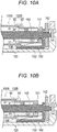
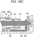
- Figs. 10A to 10C are diagrams for describing the plunger 130B and the canceling mechanism 10B according to the third modification.
- the plunger 130B includes a plunger body 132B. As illustrated in Figs. 10A to 10C , the plunger body 132B includes: an intermediate member 40 including the threaded portion 131 and a first protrusion 41; and a pressing member 50 including a second protrusion 51 and capable of pressing the gasket 135 (see Fig. 5 ).
- the canceling mechanism 10B has the first protrusion 41 and the second protrusion 51.
- the first protrusion 41 of the intermediate member 40 climbs over the second protrusion 51 of the pressing member 50 in the direction in which the pressing member 50 advances as illustrated in Fig. 10C .
- the state in which the first protrusion 41 climbs over the second protrusion 51 means that, for example, when the plunger body 132B receives an axial reaction force equal to or greater than a preset pressing force from the gasket 135 (see Fig. 5 ), the vicinity of the first protrusion 41 in the intermediate member 40 is bent in a radially inward direction intersecting the axial direction by the axial reaction force. In this case, the advancement of the pressing member 50 is stopped with respect to the intermediate member 40 that continues to advance. Then, when the intermediate member 40 of the plunger 130B continues to advance, the intermediate member 40 is disengaged from the guide wall 152 of the rotation restriction unit 150 and turns free with respect to the housing 120. Therefore, the plunger 130B rotates together with the feed screw 143 without advancing. Accordingly, the canceling mechanism 10B can prevent the transmission of the pressing force from the plunger body 132B to the gasket 135.
- the plunger body 132B of the liquid medicine administration device 100 includes: the intermediate member 40 including the threaded portion 131 and the first protrusion 41; and the pressing member 50 including the second protrusion 51 contactable to the first protrusion 41 of the intermediate member 40 and capable of pressing the gasket 135.
- the canceling mechanism 10B has the first protrusion 41 of the intermediate member 40 and the second protrusion 51 of the pressing member 50.
- the plunger body 132B advances with the rotation of the feed screw 143 due to the contact between the first protrusion 41 of the intermediate member 40 and the second protrusion 51 of the pressing member 50, while rotation with respect to the housing 120 is being restricted by the rotation restriction unit 150.
- the plunger body 132B When the plunger body 132B receives the axial reaction force from the gasket 135, the first protrusion 41 of the intermediate member 40 climbs over the second protrusion 51 of the pressing member 50 in the direction in which the pressing member 50 advances, so that the contact between the first protrusion 41 of the intermediate member 40 and the second protrusion 51 of the pressing member 50 is released, and the advancement of the plunger body 132B with the rotation of the feed screw 143 is stopped.
- the plunger body 132B when the plunger body 132B receives the axial reaction force from the gasket 135, the vicinity of the first protrusion 41 in the intermediate member 40 is bent in a radially inward direction intersecting the axial direction by the axial reaction force, and the advancement of the pressing member 50 is stopped with respect to the intermediate member 40 that continues to advance. Then, the intermediate member 40 is freed from the restriction of rotation by the rotation restriction unit 150. Therefore, the plunger 130B rotates together with the feed screw 143 without advancing. Accordingly, the canceling mechanism 10B can prevent the transmission of the pressing force from the plunger body 132B to the gasket 135.
- the configuration described above can prevent leakage of the liquid medicine when blockage occurs in the liquid delivery path of the liquid medicine.
- liquid medicine administration device according to the present invention has been described above by way of the modifications, the present invention is not limited to each of the described configurations, and can be appropriately modified on the basis of the description of the claims.
Landscapes
- Health & Medical Sciences (AREA)
- Heart & Thoracic Surgery (AREA)
- Vascular Medicine (AREA)
- Engineering & Computer Science (AREA)
- Anesthesiology (AREA)
- Biomedical Technology (AREA)
- Hematology (AREA)
- Life Sciences & Earth Sciences (AREA)
- Animal Behavior & Ethology (AREA)
- General Health & Medical Sciences (AREA)
- Public Health (AREA)
- Veterinary Medicine (AREA)
- Dermatology (AREA)
- Infusion, Injection, And Reservoir Apparatuses (AREA)
Abstract
Description
- The present invention relates to a liquid medicine administration device.
- Conventionally, a syringe pump type liquid medicine administration device has been known which administers a liquid medicine with which a liquid medicine container is filled into a living body by a pressing action of a plunger. The plunger can be configured to, for example, discharge the liquid medicine from the liquid medicine container when pushed into the liquid medicine container by a rotational driving force of a drive mechanism.
- For example,
Patent Literature 1 discloses a drive mechanism including a motor that generates a rotational driving force, a gear reduction mechanism that decreases the speed of rotation of the motor, and a feed screw that rotates in response to a torque from the gear reduction mechanism. The plunger is configured as a bearing of the feed screw, and is also configured to advance by rotation of the feed screw. - Patent Literature 1:
JP 2015-181835 A - However, in the liquid medicine administration device as described above, when blockage occurs in a liquid delivery path of the liquid medicine, a load is applied to a region on the upstream side of the blockage portion in the liquid delivery path by the plunger that is going to advance. As a result, the liquid medicine may leak out in the region upstream of the blockage portion in the liquid delivery path.
- The present invention has been accomplished in view of the above problems, and an object thereof is to provide a liquid medicine administration device capable of preventing leakage of a liquid medicine when blockage occurs in a liquid delivery path of the liquid medicine.
- A liquid medicine administration device according to the present invention includes: a liquid medicine container filled with a liquid medicine and having, at a tip, an opening through which the liquid medicine is discharged; a gasket for expelling the liquid medicine in the liquid medicine container, the gasket being slidable on an inner wall of the liquid medicine container; a plunger capable of pressing the gasket; a housing that holds the liquid medicine container and the plunger; a drive mechanism that advances the plunger toward the tip of the liquid medicine container; and a rotation restriction unit that restricts rotation of the plunger with respect to the housing. The drive mechanism includes a motor and a feed screw that rotates in response to rotation of the motor, and the plunger includes: a threaded portion threadedly engaged with the feed screw; and a plunger body that advances with the rotation of the feed screw and that presses the gasket, while the rotation of the plunger with respect to the housing is being restricted by the rotation restriction unit. The plunger is provided with a canceling mechanism that cancels transmission of a pressing force from the plunger body to the gasket when the plunger body receives an axial reaction force equal to or greater than a preset pressing force from the gasket during advancement with the rotation of the feed screw.
- According to the liquid medicine administration device of the present invention, it is possible to prevent leakage of the liquid medicine when blockage occurs in a liquid delivery path of the liquid medicine.
-
-
Fig. 1 is a side view of a liquid medicine administration system according to one embodiment of the present invention. -
Fig. 2 is a diagram schematically illustrating an example of use of the liquid medicine administration system illustrated inFig. 1 . -
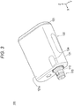
Fig. 3 is a schematic perspective view of a liquid medicine administration device constituting the liquid medicine administration system illustrated inFig. 1 . -
Fig. 4 is an exploded perspective view of the liquid medicine administration device illustrated inFig. 1 . -
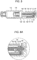
Fig. 5 is a sectional view illustrating a canceling mechanism of the liquid medicine administration device illustrated inFig. 1 and a periphery thereof. -
Fig. 6A is a partially enlarged view of the liquid medicine administration device illustrated inFig. 5 . -
Fig. 6B is a partially enlarged view of the liquid medicine administration device illustrated inFig. 5 . -
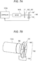
Fig. 7A is a block diagram of a control system of a liquid medicine administration device according to a first modification. -
Fig. 7B is a diagram schematically illustrating a rotation detector and the like according to the first modification. -
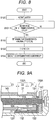
Fig. 8 is a flowchart illustrating operation of a controller according to the first modification. -
Fig. 9A is a partially enlarged sectional view illustrating a canceling mechanism and its periphery according to a second modification. -
Fig. 9B is a partially enlarged sectional view illustrating the canceling mechanism and its periphery according to the second modification. -
Fig. 9C is a partially enlarged sectional view illustrating the canceling mechanism and its periphery according to the second modification. -
Fig. 10A is a partially enlarged sectional view illustrating a canceling mechanism and its periphery according to a third modification. -
Fig. 10B is a partially enlarged sectional view illustrating the canceling mechanism and its periphery according to the third modification. -
Fig. 10C is a partially enlarged sectional view illustrating the canceling mechanism and its periphery according to the third modification. - Embodiments of the present invention will now be described with reference to the accompanying drawings. It should be noted that the following description is not intended to limit the technical scopes and meanings of terms set forth in the claims of the present application. Further, the dimensional ratios in the drawings are exaggerated for convenience of description, and may differ from the actual ratios.
-
Figs. 1 to 4 are diagrams for describing a liquidmedicine administration system 1, a liquidmedicine administration device 100, and anadministration instrument 200 according to the present embodiment.Figs. 5 to 6B are diagrams for describing acanceling mechanism 10 according to the present embodiment. An arrow X in each drawing indicates the "longitudinal direction (longitudinal direction of a liquid medicine container 110)" of the liquidmedicine administration device 100, an arrow Y indicates the "width direction (depth direction)" of the liquidmedicine administration device 100, and an arrow Z indicates the "height direction" of the liquidmedicine administration device 100. - The liquid
medicine administration system 1 is used to administer a liquid medicine into a living body. As illustrated inFig. 1 , the liquidmedicine administration system 1 includes the liquidmedicine administration device 100 and theadministration instrument 200. - As illustrated in
Fig. 2 , the liquidmedicine administration device 100 and theadministration instrument 200 are of a patch type that is attached to the body surface (skin) H of a user when used. The body part of the user to which the liquidmedicine administration device 100 and theadministration instrument 200 are attached is not particularly limited, and examples thereof include the abdomen and the thigh. - The liquid
medicine administration system 1 can continuously administer a liquid medicine (not shown) with which theliquid medicine container 110 is filled included in the liquidmedicine administration device 100 into a living body for relatively a long period of time (for example, several minutes to several hours) by a pressing action of a later-describedplunger 130. Note that the liquidmedicine administration system 1 may administer the liquid medicine at intervals into the living body. - As illustrated in
Figs. 3 to 5 , the liquidmedicine administration device 100 includes: aliquid medicine container 110 filled with a liquid medicine; aplunger 130 that expels the liquid medicine in theliquid medicine container 110; ahousing 120 that holds theliquid medicine container 110 and theplunger 130; adrive mechanism 140 that advances theplunger 130 toward a tip of theliquid medicine container 110; arotation restriction unit 150 that restricts rotation of theplunger 130; adetector 160 that detects a position of theplunger 130; and acontroller 170 that controls operations of thedrive mechanism 140 and thedetector 160. - As illustrated in
Figs. 3 and4 , thehousing 120 has a box-shaped housing body 121 having a housing space formed therein, achassis 122 that is housed in the housing space of thehousing body 121 and can be fixed to thehousing body 121, and alid member 123 attached to thehousing body 121 with thechassis 122 being housed in the housing space. - As illustrated in
Figs. 3 and4 , awindow 124 is formed in anupper surface 121a of thehousing body 121 to allow the inside of the housing space to be visible from the outside of thehousing 120. Thewindow 124 is formed by providing a transparent or semitransparent portion on a part of thehousing body 121. - As illustrated in
Figs. 3 and4 , a base end opening 125 through which thechassis 122 is inserted into the housing space of thehousing body 121 is formed in the base end of thehousing body 121 in the longitudinal direction. The base end opening 125 of thehousing body 121 is closed by thelid member 123 with thechassis 122 housed in the housing space. - A
bottom surface 121b of thehousing body 121 is provided with a sheet-shaped adhesive portion (not shown) that can adhere to the body surface H of the user. In an initial state before the liquidmedicine administration device 100 is attached to the user, a releasable protective sheet is attached to an adhesive surface of the adhesive portion. - As illustrated in
Fig. 4 , thechassis 122 holds theliquid medicine container 110, theplunger 130, thedrive mechanism 140, therotation restriction unit 150, thedetector 160, thecontroller 170, and apower supply unit 180. - The
liquid medicine container 110 is a so-called prefilled type liquid medicine container. Therefore, the liquid medicine is charged in advance in alumen 111 of theliquid medicine container 110. Examples of the liquid medicine include protein preparations, narcotic analgesics, and diuretics. - A sealing member (not shown) for preventing the liquid medicine from leaking is disposed at a tip opening (discharge port) formed at a
tip 112 of theliquid medicine container 110. As illustrated inFig. 3 , thetip 112 of theliquid medicine container 110 is disposed to protrude from thehousing body 121 to the outside. In addition, a mountingportion 115 that is to be connected to a tube 240 (seeFig. 1 ) described later is attached to the tip of theliquid medicine container 110 that protrudes from thehousing body 121. - As illustrated in
Fig. 4 , theplunger 130 is inserted into thelumen 111 of theliquid medicine container 110. Agasket 135 slidable on an inner wall of theliquid medicine container 110 is disposed at a tip of theplunger 130. The outer periphery of thegasket 135 is in liquid-tight contact with the inner peripheral surface of theliquid medicine container 110, whereby the base end side of thegasket 135 is liquid-tightly sealed. - The
plunger 130 is composed of a cylindrical member. - As illustrated in
Fig. 5 , theplunger 130 includes: a threadedportion 131 threadedly engaged with thefeed screw 143; and aplunger body 132 that advances with the rotation of thefeed screw 143 and presses thegasket 135, while rotation with respect to the housing 120 (chassis 122) is being restricted by therotation restriction unit 150. Theplunger body 132 has a notch (not illustrated) on a surface facing thechassis 122, and holds therotation restriction unit 150 to be described later. - The
plunger 130 is provided with a cancelingmechanism 10 that cancels the transmission of the pressing force from theplunger body 132 to thegasket 135 when receiving an axial reaction force equal to or greater than a preset pressing force from thegasket 135 during advancement with the rotation of thefeed screw 143. The structure of the cancelingmechanism 10 will be described later. In the present specification, the preset pressing force means a force required to expel the liquid medicine in theliquid medicine container 110 by theplunger body 132 pressing thegasket 135 in a case where blockage does not occur in the liquid delivery path of the liquid medicine. In addition, the axial reaction force means a drag force in a direction opposite to the direction in which theplunger body 132 is advanced in the longitudinal direction (X direction) to expel the liquid medicine in theliquid medicine container 110. - As illustrated in
Fig. 4 , thedrive mechanism 140 includes: amotor 141 that receives a drive current from thepower supply unit 180 to generate a rotational driving force; aspeed reduction mechanism 142 including a gear that transmits the rotational driving force of themotor 141, and the like; and afeed screw 143 connected to thespeed reduction mechanism 142. - The
feed screw 143 converts the rotary motion transmitted from thespeed reduction mechanism 142 into a linear motion, and advances theplunger 130 in the longitudinal direction. - In the present embodiment, the
plunger 130 advances in the longitudinal direction with the rotation of thefeed screw 143, while the rotation of theplunger 130 with respect to thehousing 120 is being restricted by therotation restriction unit 150. As theplunger 130 advances toward the tip of theliquid medicine container 110, the liquid medicine in thelumen 111 of theliquid medicine container 110 is expelled to the tube 240 (seeFig. 1 ). - The
rotation restriction unit 150 restricts rotation of theplunger 130 with respect to thehousing 120. As illustrated inFig. 5 , therotation restriction unit 150 has abottom surface 151 fixed to thehousing 120 and aguide wall 152 that restricts the rotation of theplunger 130 to urge theplunger 130 to advance in the longitudinal direction. Theguide wall 152 is erected in the height direction (Z direction) from thebottom surface 151. Theguide wall 152 is disposed so as to protrude into the internal space of theplunger 130 from a notch (not illustrated) formed in a surface of theplunger 130 facing thechassis 122. In the present embodiment, theplunger 130 advances in the longitudinal direction with the rotation of thefeed screw 143, while the rotation of theplunger 130 with respect to thehousing 120 is being restricted by therotation restriction unit 150. As theplunger 130 advances toward the tip of theliquid medicine container 110, the liquid medicine in thelumen 111 of theliquid medicine container 110 is expelled to the tube 240 (seeFig. 1 ). - As illustrated in
Fig. 4 , thedetector 160 detects that theplunger 130 has advanced to a predetermined position L1. The predetermined position L1 can be set at any position in the longitudinal direction between a liquid delivery start position of the plunger 130 (the initial position of the plunger 130) to a liquid delivery end position (the position where theplunger 130 completely expels the liquid medicine in theliquid medicine container 110 to the tube 240). - The
detector 160 can be constituted by, for example, a known contact sensor that transmits a predetermined electric signal when a detected portion (not illustrated) provided at the base end of theplunger 130 comes into contact therewith. - The
controller 170 controls the operation of delivering the liquid medicine by the liquidmedicine administration device 100 on the basis of the detection result by thedetector 160. Thecontroller 170 can be implemented by, for example, a known microcomputer (electronic circuit element) mounted with a CPU, a RAM, a ROM, and the like. Thecontroller 170 centrally controls operation of thedrive mechanism 140, thedetector 160, and thepower supply unit 180. - In the present embodiment, the
controller 170 determines that a predetermined amount of the liquid medicine is not expelled from theliquid medicine container 110 when a predetermined time has elapsed after a command to start the operation is given to thedrive mechanism 140, and thedetector 160 does not detect that theplunger 130 has advanced to the predetermined position L1. For example, the predetermined time can be set to be longer than a time during which theplunger 130 can sufficiently move to the predetermined position L1 after thecontroller 170 gives a command to start the operation to thedrive mechanism 140 in a case where blockage does not occur in the liquid delivery path of the liquid medicine. When determining that a predetermined amount of the liquid medicine is not expelled, thecontroller 170 stops themotor 141 and notifies the user of the current situation. - The
power supply unit 180 can be composed of, for example, a known battery. - Next, the structure of the canceling
mechanism 10 will be described with reference toFigs. 6A and6B . - As illustrated in
Fig. 6A , the cancelingmechanism 10 includes a threadedportion 131. Therefore, the cancelingmechanism 10 according to the present embodiment is threadedly engaged with thefeed screw 143. When blockage occurs in theadministration instrument 200 such as thetube 240 which is connectable to the liquidmedicine administration device 100, theplunger 130 including the cancelingmechanism 10 receives an axial reaction force equal to or greater than a preset pressing force from the gasket 135 (seeFig. 5 ). Therefore, a larger axial reaction force than that when no blockage occurs acts on the canceling mechanism 10 (threaded portion 131) from thefeed screw 143. Accordingly, when blockage occurs, the canceling mechanism 10 (threaded portion 131) is worn by thefeed screw 143 that rotates by thedrive mechanism 140 to advance theplunger body 132 in the longitudinal direction as illustrated inFig. 6B . - When the canceling
mechanism 10 is worn by thefeed screw 143, thefeed screw 143 turns free with respect to the threadedportion 131. Therefore, thefeed screw 143 cannot transmit the rotational driving force of themotor 141 to theplunger body 132. Accordingly, when blockage occurs in the liquid delivery path of the liquid medicine, the cancelingmechanism 10 can cancel the transmission of the pressing force from theplunger 130 including theplunger body 132 to thegasket 135. - Note that the material of the canceling
mechanism 10 is not particularly limited, and a metal material or a resin material may be used as long as it is a soft material that is worn by thefeed screw 143 when receiving an axial reaction force equal to or greater than a preset pressing force from thegasket 135. - The height of the screw thread of the canceling
mechanism 10 may be lower than the height of the screw thread of thefeed screw 143. With this configuration, the cancelingmechanism 10 and thefeed screw 143 are threadedly engaged with each other with their screw threads being lightly engaged with each other. Therefore, when the cancelingmechanism 10 is worn by thefeed screw 143, the screw thread of thefeed screw 143 turns free earlier with respect to the threadedportion 131. Accordingly, the cancelingmechanism 10 can further shorten the time from when the blockage occurs in the liquid delivery path of the liquid medicine until the transmission of the pressing force from theplunger body 132 to thegasket 135 is canceled. - As illustrated in
Figs. 1 and 2 , theadministration instrument 200 is connectable to the liquidmedicine administration device 100. - The
administration instrument 200 includes aconnector 210, aneedle tube 220 that is inserted into a living body, a puncture portion (cannula housing) 230, thetube 240, and apuncture assistance tool 250 that assists the puncture of the living body with theneedle tube 220. - The
connector 210 is connectable to the liquidmedicine administration device 100 via a mountingportion 215 fixed to theconnector 210. The mountingportion 215 can be connected to the liquidmedicine administration device 100 by being externally fitted to the mounting portion 115 (seeFig. 4 ) which is provided at thetip 112 of theliquid medicine container 110 protruding to the outside of thehousing 120. - The mounting
portion 215 has inside a connecting needle (not shown) capable of piercing a sealing member (not shown) provided at the tip of theliquid medicine container 110. - The
tube 240 communicates with thelumen 111 of theliquid medicine container 110 via the connecting needle. - A flow path (not shown) that connects the
tube 240 and the lumen of theneedle tube 220 is formed inside thepuncture portion 230. The liquid medicine delivered to thepuncture portion 230 via thetube 240 is administered into the living body through the flow path formed inside thepuncture portion 230 and theneedle tube 220. - When the liquid medicine is delivered to the user, the
puncture assistance tool 250 is attached to thepuncture portion 230. Thepuncture assistance tool 250 holds an introducer needle (inner needle) 251. Theintroducer needle 251 projects from the tip of theneedle tube 220 when thepuncture assistance tool 250 is attached to thepuncture portion 230. The user can insert theneedle tube 220 into the living body, while preventing theneedle tube 220 from having any troubles such as breakage, by piercing the living body with theneedle tube 220 with theintroducer needle 251 inserted into theneedle tube 220. - The
puncture assistance tool 250 is removed from thepuncture portion 230 after theneedle tube 220 is inserted into the living body. Theintroducer needle 251 is withdrawn from the lumen of theneedle tube 220 when thepuncture assistance tool 250 is removed from thepuncture portion 230. - After the
needle tube 220 is inserted into the living body, thepuncture assistance tool 250 is removed, and thepuncture portion 230 is left on the body surface H of the user with theneedle tube 220 left in the living body. In this state, theplunger 130 of the liquidmedicine administration device 100 advances in theliquid medicine container 110, so that the liquid medicine with which theliquid medicine container 110 is filled is delivered to the lumen of theneedle tube 220 through thetube 240 and the flow path of thepuncture portion 230. - The
introducer needle 251 can be, for example, a metal needle. Further, theneedle tube 220 can be composed of, for example, a tubular member (cannula) made of resin. - Similar to the liquid
medicine administration device 100, theadministration instrument 200 is of a patch type that is attached to the body surface H of the user when used. The contact surface (bottom surface) 231 of thepuncture portion 230 of theadministration instrument 200 is provided with a sheet-shaped adhesive portion (not shown) that can adhere to the body surface. In an initial state before theadministration instrument 200 is attached to the user, a releasable protective sheet is attached to an adhesive surface of the adhesive portion. - As described above, the liquid
medicine administration device 100 according to the present embodiment includes: theliquid medicine container 110 filled with a liquid medicine and having, at a tip, an opening through which the liquid medicine can be discharged; thegasket 135 for expelling the liquid medicine in theliquid medicine container 110, thegasket 135 being slidable on the inner wall of theliquid medicine container 110; theplunger 130 capable of pressing thegasket 135; thehousing 120 that holds theliquid medicine container 110 and theplunger 130; thedrive mechanism 140 that advances theplunger 130 toward the tip of theliquid medicine container 110; and therotation restriction unit 150 that restricts the rotation of theplunger 130 with respect to thehousing 120. Thedrive mechanism 140 includes themotor 141 and thefeed screw 143 that rotates in response to the rotation of themotor 141. Theplunger 130 includes: the threadedportion 131 threadedly engaged with thefeed screw 143; and theplunger body 132 that advances with the rotation of thefeed screw 143 and presses thegasket 135, while the rotation of theplunger 130 with respect to thehousing 120 is being restricted by therotation restriction unit 150. Theplunger 130 is provided with the cancelingmechanism 10 that cancels the transmission of the pressing force from theplunger body 132 to thegasket 135 when theplunger body 132 receives an axial reaction force equal to or greater than a preset pressing force from thegasket 135 during advancement with the rotation of thefeed screw 143. - According to the liquid
medicine administration device 100, when blockage occurs in the liquid delivery path of the liquid medicine, theplunger 130 receives an axial reaction force equal to or greater than the preset pressing force from thegasket 135. The cancelingmechanism 10 cancels the transmission of the pressing force from theplunger body 132 to thegasket 135 when theplunger 130 receives an axial reaction force equal to or greater than a preset pressing force from thegasket 135. As a result, thegasket 135 cannot obtain torque for advancement toward the tip of theliquid medicine container 110. Thus, the configuration described above can prevent leakage of the liquid medicine when blockage occurs in the liquid delivery path of the liquid medicine. - In addition, the canceling
mechanism 10 includes the threadedportion 131. When receiving an axial reaction force from thegasket 135, the threadedportion 131 is worn by thefeed screw 143, and thefeed screw 143 turns free with respect to the threadedportion 131. Therefore, thefeed screw 143 cannot transmit the rotational driving force of themotor 141 to theplunger body 132. Accordingly, when blockage occurs in the liquid delivery path of the liquid medicine, the cancelingmechanism 10 can cancel the transmission of the pressing force from theplunger 130 including theplunger body 132 to thegasket 135. Thus, the configuration described above can prevent leakage of the liquid medicine when blockage occurs in the liquid delivery path of the liquid medicine. - The liquid
medicine administration device 100 further includes thedetector 160 detecting that theplunger 130 has advanced to the predetermined position L1, and thecontroller 170 that controls the start and stop of the operation of thedrive mechanism 140. Thecontroller 170 determines that a predetermined amount of the liquid medicine is not expelled from theliquid medicine container 110, when a predetermined time has elapsed after a command to start the operation is given to thedrive mechanism 140, and thedetector 160 does not detect that theplunger 130 has advanced to the predetermined position L1. Therefore, when blockage occurs in the liquid delivery path of the liquid medicine, thecontroller 170 can give a command to stop the operation of thedrive mechanism 140 on the basis of the detection result by thedetector 160. Thus, the configuration described above can prevent leakage of the liquid medicine when blockage occurs in the liquid delivery path of the liquid medicine. - While the liquid medicine administration device according to the present invention has been described above by way of the embodiment, the present invention is not limited to each of the described configurations, and can be appropriately modified on the basis of the description of the claims. In the following, a modification of the motor will be described. In the description of the modification, the description of the configuration and details of the liquid
medicine administration system 1 described above will be appropriately omitted. - A liquid
medicine administration device 100 according to the first modification uses a DC motor as amotor 141A for the purpose of miniaturization and cost reduction in order to facilitate handling at the time of use and to save a storage space at the time of storage. The DC motor is a coreless motor which is easily downsized and has high torque efficiency with respect to electric power. The DC motor has a characteristic that a current supplied to the DC motor and the rotation speed of the DC motor are different depending on the magnitude of a load torque. Thecontroller 170 detects an administration abnormality (a situation in which a predetermined amount of the liquid medicine is not expelled from the liquid medicine container 110) using the characteristics of themotor 141A. Therefore, acontroller 170A controls thedrive mechanism 140 as follows. - A specific operation of the
controller 170A will be described with reference toFigs. 7A, 7B , and8 .Fig. 7A is a block diagram of a control system of the liquidmedicine administration device 100 according to the first modification.Fig. 7B is a diagram schematically illustrating arotation detector 161 and the like according to the first modification.Fig. 8 is a flowchart illustrating operation of thecontroller 170A according to the first modification. - As illustrated in
Fig. 7A , thecontroller 170A is electrically connected to themotor 141A. A rotation shaft of themotor 141A is mechanically connected to thespeed reduction mechanism 142. In thespeed reduction mechanism 142, anencoder 162 is provided as arotation detector 161 that detects the rotation speed of themotor 141A. - As illustrated in
Fig. 7B , theencoder 162 includes aphotointerrupter 144 including an optical sensor, and aslit plate 145 having a large number of slits which are radially formed. The rotation of themotor 141A is detected by detecting whether or not light passes through the slits of theslit plate 145 with the optical sensor of thephotointerrupter 144. Thephotointerrupter 144 is electrically connected to thecontroller 170A. In the present embodiment, theencoder 162 using thephotointerrupter 144 is described as an example of therotation detector 161, but an encoder using a magnetic sensor may be used. - When the
controller 170A rotates themotor 141A, thespeed reduction mechanism 142 is driven, so that theplunger 130 advances in the liquid medicine container 110 (seeFig. 4 ). At this time, theencoder 162 provided adjacent to thespeed reduction mechanism 142 detects the rotation of themotor 141A, and thecontroller 170A calculates the rotation speed of themotor 141A on the basis of the rotation of themotor 141A detected by theencoder 162. The rotation of themotor 141A detected by theencoder 162 is fed back to thecontroller 170A, and thecontroller 170A calculates the rotation speed of themotor 141A or determines whether or not themotor 141A is rotating on the basis of the feedback result. Note that therotation detector 161 can also be provided as a part of thespeed reduction mechanism 142 Specifically, theslit plate 145 is eliminated, and instead, a large number of slits are radially provided in the gear of thespeed reduction mechanism 142. The optical sensor of thephotointerrupter 144 detects whether or not light passes through the slits provided in the gear, whereby the rotation of themotor 141A is detected. In this case, theencoder 162 is constituted by the gear of thespeed reduction mechanism 142 and thephotointerrupter 144. With this configuration, the liquid medicine with which theliquid medicine container 110 is filled is delivered to the lumen of theneedle tube 220 via the liquid delivery path of the liquid medicine such as thetube 240 and thepuncture portion 230, and is administered to the living body. - As illustrated in
Fig. 8 , thecontroller 170A activates themotor 141A at the time of administering the liquid medicine to the living body (S100), and determines whether or not the rotation speed of themotor 141A is higher than a predetermined rotation speed (S101). The rotation speed of themotor 141A at the time of administering the liquid medicine to the living body is set in advance according to the rate of administration of the liquid medicine. When the rotation speed of themotor 141A is lower than (not higher than) the predetermined rotation speed (S101: NO), it can be determined that the liquid medicine is normally administered, so that the administration of the liquid medicine is continued. On the other hand, when the rotation speed of themotor 141A is higher than the predetermined rotation speed (exceeds the predetermined rotation speed), it is considered that theplunger body 132 receives an axial reaction force equal to or greater than the pressing force from thegasket 135 due to an occurrence of an abnormality such as blockage of the liquid delivery path of the liquid medicine, resulting in that the transmission of the pressing force from theplunger 130 including theplunger body 132 to thegasket 135 is canceled by the cancelingmechanism 10, and the load on themotor 141A is reduced (S101: YES). Therefore, thecontroller 170A detects an administration abnormality (S102). Next, thecontroller 170A stops themotor 141A (S103) and notifies the user of the administration abnormality (S104). The administration abnormality may be notified by lighting or blinking an LED provided on a case of the liquidmedicine administration device 100, or by outputting a sound from a speaker provided inside the case of the liquidmedicine administration device 100. In addition, the occurrence of the administration abnormality may be wirelessly reported to an external computer. - As described above, in the liquid
medicine administration device 100 according to the first modification, themotor 141A is a DC motor. The liquidmedicine administration device 100 further includes therotation detector 161 that detects rotation of the DC motor and thecontroller 170A that controls rotation of the DC motor. Thecontroller 170A stops the rotation of themotor 141A when the rotation speed of themotor 141A calculated based on the rotation of themotor 141A detected by therotation detector 161 becomes equal to or higher than a predetermined speed. Therefore, in a case where blockage occurs in the liquid delivery path of the liquid medicine, thecontroller 170A can prevent themotor 141A from being continuously driven on the basis of the detection result of thedetector 160. Thus, the configuration described above can prevent leakage of the liquid medicine when blockage occurs in the liquid delivery path of the liquid medicine. - While an example of the configuration of a medical device has been described above, the present invention is not limited to the description of the above embodiment, and various modifications are possible without departing from the gist of the present invention.
- Next, modifications of the plunger and the canceling mechanism will be described by way of a second modification and a third modification. A liquid
medicine administration device 100 according to the second modification includes aplunger 130A and a cancelingmechanism 10A having structures different from those of theplunger 130 and the cancelingmechanism 10 according to the above embodiment.Figs. 9A to 9C are diagrams for describing theplunger 130A and the cancelingmechanism 10A according to the second modification. - The
plunger 130A includes aplunger body 132A. - As illustrated in
Figs. 9A to 9C , theplunger body 132A includes abase end portion 21 having a threadedportion 131, atip portion 23 that is in contact with the gasket 135 (seeFig. 5 ), and anintermediate portion 22 formed between thebase end portion 21 and thetip portion 23. - The canceling
mechanism 10A has athin portion 31 formed in theintermediate portion 22 of theplunger body 132A. - As illustrated in
Figs. 9A and9B , theplunger body 132A advances with the rotation of thefeed screw 143 connected to thespeed reduction mechanism 142, while rotation with respect to thehousing 120 is being restricted by therotation restriction unit 150. - When blockage occurs in the liquid delivery path of the liquid medicine, the
thin portion 31 is bent or broken in a direction intersecting the direction in which theplunger body 132A advances. Note thatFig. 9C illustrates an example in which thethin portion 31 is broken in a direction intersecting the direction in which theplunger body 132A advances. - The state in which the
thin portion 31 is bent means that, for example, when theplunger body 132A receives an axial reaction force equal to or greater than a preset pressing force from the gasket 135 (seeFig. 5 ), theplunger body 132A is bent at thethin portion 31 in a direction intersecting the axial direction, and theplunger body 132A is compressed and deformed in the axial direction, resulting in that the distance between thebase end portion 21 and thetip portion 23 is decreased. In this case, the advancement of thetip portion 23 is stopped with respect to thebase end portion 21 that continues to advance. Then, when thebase end portion 21 of theplunger 130A continues to advance, thebase end portion 21 is disengaged from theguide wall 152 of therotation restriction unit 150 and turns free with respect to thehousing 120. Therefore, theplunger 130A rotates together with thefeed screw 143 without advancing. Accordingly, the cancelingmechanism 10A (thin portion 31) can prevent the transmission of the pressing force from theplunger body 132A to thegasket 135. - The minimum thickness of the
thin portion 31 is not particularly limited as long as it allows thethin portion 31 to be easily bent when blockage occurs in the liquid delivery path of the liquid medicine. - As described above, the
plunger body 132A of the liquidmedicine administration device 100 according to the second modification includes thebase end portion 21 having the threadedportion 131, thetip portion 23 that is in contact with thegasket 135, and theintermediate portion 22 formed between thebase end portion 21 and thetip portion 23. The cancelingmechanism 10A has athin portion 31 formed in theintermediate portion 22 of theplunger body 132A. When receiving the axial reaction force from thegasket 135, thethin portion 31 is bent or broken in a direction intersecting the direction in which theplunger body 132A advances. Therefore, the distance between thebase end portion 21 and thetip portion 23 of theplunger body 132A is decreased due to thethin portion 31 being bent or broken, and the restriction of rotation of theplunger 130A with respect to thehousing 120 by therotation restriction unit 150 is removed. Thus, the advancement of theplunger body 132A with the rotation of thefeed screw 143 is stopped. - According to the liquid
medicine administration device 100 described above, when theplunger body 132A receives an axial reaction force from thegasket 135, theplunger body 132A is bent at thethin portion 31 in a direction intersecting the axial direction, and the advancement of thetip portion 23 is stopped with respect to thebase end portion 21 that continues to advance. Then, thebase end portion 21 is freed from the restriction of rotation by therotation restriction unit 150. Therefore, theplunger 130A rotates together with thefeed screw 143 without advancing. Accordingly, the cancelingmechanism 10A including thethin portion 31 can prevent the transmission of the pressing force from theplunger body 132A to thegasket 135. Thus, the configuration described above can prevent leakage of the liquid medicine when blockage occurs in the liquid delivery path of the liquid medicine. - Next, a liquid
medicine administration device 100 according to the third modification will be described with reference toFigs. 10A to 10C . The liquidmedicine administration device 100 according to the third modification includes aplunger 130B and a cancelingmechanism 10B having structures different from those of theplunger 130 and the cancelingmechanism 10 according to the above embodiment.Figs. 10A to 10C are diagrams for describing theplunger 130B and the cancelingmechanism 10B according to the third modification. - The
plunger 130B includes aplunger body 132B. As illustrated inFigs. 10A to 10C , theplunger body 132B includes: anintermediate member 40 including the threadedportion 131 and afirst protrusion 41; and a pressingmember 50 including asecond protrusion 51 and capable of pressing the gasket 135 (seeFig. 5 ). - The canceling
mechanism 10B has thefirst protrusion 41 and thesecond protrusion 51. - As illustrated in
Figs. 10A and 10B , when thefirst protrusion 41 of theintermediate member 40 and thesecond protrusion 51 of the pressingmember 50 contact each other, theplunger body 132B advances with the rotation of thefeed screw 143 connected to thespeed reduction mechanism 142, while rotation with respect to thehousing 120 is being restricted by therotation restriction unit 150. - On the other hand, when blockage occurs in the liquid delivery path of the liquid medicine, the
first protrusion 41 of theintermediate member 40 climbs over thesecond protrusion 51 of the pressingmember 50 in the direction in which the pressingmember 50 advances as illustrated inFig. 10C . - The state in which the
first protrusion 41 climbs over thesecond protrusion 51 means that, for example, when theplunger body 132B receives an axial reaction force equal to or greater than a preset pressing force from the gasket 135 (seeFig. 5 ), the vicinity of thefirst protrusion 41 in theintermediate member 40 is bent in a radially inward direction intersecting the axial direction by the axial reaction force. In this case, the advancement of the pressingmember 50 is stopped with respect to theintermediate member 40 that continues to advance. Then, when theintermediate member 40 of theplunger 130B continues to advance, theintermediate member 40 is disengaged from theguide wall 152 of therotation restriction unit 150 and turns free with respect to thehousing 120. Therefore, theplunger 130B rotates together with thefeed screw 143 without advancing. Accordingly, the cancelingmechanism 10B can prevent the transmission of the pressing force from theplunger body 132B to thegasket 135. - As described above, the
plunger body 132B of the liquidmedicine administration device 100 according to the third modification includes: theintermediate member 40 including the threadedportion 131 and thefirst protrusion 41; and the pressingmember 50 including thesecond protrusion 51 contactable to thefirst protrusion 41 of theintermediate member 40 and capable of pressing thegasket 135. The cancelingmechanism 10B has thefirst protrusion 41 of theintermediate member 40 and thesecond protrusion 51 of the pressingmember 50. Theplunger body 132B advances with the rotation of thefeed screw 143 due to the contact between thefirst protrusion 41 of theintermediate member 40 and thesecond protrusion 51 of the pressingmember 50, while rotation with respect to thehousing 120 is being restricted by therotation restriction unit 150. When theplunger body 132B receives the axial reaction force from thegasket 135, thefirst protrusion 41 of theintermediate member 40 climbs over thesecond protrusion 51 of the pressingmember 50 in the direction in which the pressingmember 50 advances, so that the contact between thefirst protrusion 41 of theintermediate member 40 and thesecond protrusion 51 of the pressingmember 50 is released, and the advancement of theplunger body 132B with the rotation of thefeed screw 143 is stopped. - According to the liquid
medicine administration device 100, when theplunger body 132B receives the axial reaction force from thegasket 135, the vicinity of thefirst protrusion 41 in theintermediate member 40 is bent in a radially inward direction intersecting the axial direction by the axial reaction force, and the advancement of the pressingmember 50 is stopped with respect to theintermediate member 40 that continues to advance. Then, theintermediate member 40 is freed from the restriction of rotation by therotation restriction unit 150. Therefore, theplunger 130B rotates together with thefeed screw 143 without advancing. Accordingly, the cancelingmechanism 10B can prevent the transmission of the pressing force from theplunger body 132B to thegasket 135. Thus, the configuration described above can prevent leakage of the liquid medicine when blockage occurs in the liquid delivery path of the liquid medicine. - While the liquid medicine administration device according to the present invention has been described above by way of the modifications, the present invention is not limited to each of the described configurations, and can be appropriately modified on the basis of the description of the claims.
- This application is based on
Japanese Patent Application No. 2019-066307 filed on March 29, 2019 -
- 1
- liquid medicine administration system
- 10, 10A, 10B
- canceling mechanism
- 21
- base end portion
- 22
- intermediate portion
- 23
- tip portion
- 31
- thin portion
- 40
- intermediate member
- 41
- first protrusion
- 50
- pressing member
- 51
- second protrusion
- 100
- liquid medicine administration device
- 110
- liquid medicine container
- 120
- housing
- 122
- chassis
- 130, 130A, 130B
- plunger
- 131
- threaded portion
- 132, 132A, 132B
- plunger body
- 135
- gasket
- 140
- drive mechanism
- 141, 141A
- motor
- 142
- speed reduction mechanism
- 143
- feed screw
- 144
- photointerrupter
- 145
- slit plate
- 150
- rotation restriction unit
- 160
- detector
- 161
- rotation detector
- 162
- encoder
- 170, 170A
- controller
- 180
- power supply unit
- 200
- administration instrument
- X
- longitudinal direction
- L1
- predetermined position of plunger
Claims (6)
- A liquid medicine administration device comprising:a liquid medicine container filled with a liquid medicine and having, at a tip, an opening through which the liquid medicine is discharged;a gasket for expelling the liquid medicine in the liquid medicine container, the gasket being slidable on an inner wall of the liquid medicine container;a plunger capable of pressing the gasket;a housing that holds the liquid medicine container and the plunger;a drive mechanism that advances the plunger toward the tip of the liquid medicine container; anda rotation restriction unit that restricts rotation of the plunger with respect to the housing, whereinthe drive mechanism includes a motor, and a feed screw that rotates in response to the drive torque,the plunger has a threaded portion threadedly engaged with the feed screw, and a plunger body that advances with the rotation of the feed screw and presses the gasket, while the rotation of the plunger with respect to the housing is being restricted by the rotation restriction unit, andthe plunger is provided with a canceling mechanism that cancels transmission of a pressing force from the plunger body to the gasket when the plunger body receives an axial reaction force equal to or greater than a preset pressing force from the gasket during advancement with the rotation of the feed screw.
- The liquid medicine administration device according to claim 1, whereinthe canceling mechanism includes the threaded portion, andwhen the threaded portion receives the axial reaction force from the gasket, the threaded portion is worn by the feed screw, and the feed screw turns free with respect to the threaded portion.
- The liquid medicine administration device according to claim 1, whereinthe plunger body includes a base end portion having the threaded portion, a tip portion that is in contact with the gasket, and an intermediate portion formed between the base end portion and the tip portion,the canceling mechanism has a thin portion formed in the intermediate portion of the plunger body,when receiving the axial reaction force from the gasket, the thin portion is bent or broken in a direction intersecting a direction in which the plunger body advances, anddue to the thin portion being bent or broken, a distance between the base end portion and the tip portion of the plunger body decreases, the restriction of rotation of the plunger with respect to the housing by the rotation restriction unit is removed, and advancement of the plunger body with the rotation of the feed screw is stopped.
- The liquid medicine administration device according to claim 1, wherein
the plunger body includes:an intermediate member including the threaded portion and a first protrusion; anda pressing member that includes a second protrusion contactable to the first protrusion of the intermediate member and that is capable of pressing the gasket,the canceling mechanism includes the first protrusion of the intermediate member and the second protrusion of the pressing member,the plunger body advances with the rotation of the feed screw due to contact between the first protrusion of the intermediate member and the second protrusion of the pressing member, while the rotation of the plunger with respect to the housing is being restricted by the rotation restriction unit, andwhen the plunger body receives the axial reaction force from the gasket, the first protrusion of the intermediate member climbs over the second protrusion of the pressing member in a direction in which the pressing member advances, so that the contact between the first protrusion of the intermediate member and the second protrusion of the pressing member is released, and the advancement of the plunger body with the rotation of the feed screw is stopped. - The liquid medicine administration device according to any one of claims 1 to 4, further comprising:a detector configured to detect that the plunger has advanced to a predetermined position; anda controller configured to control start and end of operation of the drive mechanism, whereinthe controller determines that a predetermined amount of the liquid medicine has not been expelled from the liquid medicine container, when a predetermined time has elapsed after a command to start the operation is given to the drive mechanism and when the detector does not detect that the plunger has advanced to the predetermined position.
- The liquid medicine administration device according to any one of claims 1 to 4, whereinthe motor is a DC motor,the liquid medicine administration device further includes a rotation detector that detects rotation of the DC motor, and a controller that controls the rotation of the DC motor, andthe controller stops the rotation of the DC motor when a rotation speed of the DC motor calculated based on the rotation of the DC motor detected by the rotation detector becomes equal to or higher than a predetermined speed.
Applications Claiming Priority (2)
| Application Number | Priority Date | Filing Date | Title |
|---|---|---|---|
| JP2019066307 | 2019-03-29 | ||
| PCT/JP2020/006288 WO2020202853A1 (en) | 2019-03-29 | 2020-02-18 | Drug solution administration device |
Publications (3)
| Publication Number | Publication Date |
|---|---|
| EP3925647A1 true EP3925647A1 (en) | 2021-12-22 |
| EP3925647A4 EP3925647A4 (en) | 2022-04-13 |
| EP3925647B1 EP3925647B1 (en) | 2025-02-12 |
Family
ID=72668965
Family Applications (1)
| Application Number | Title | Priority Date | Filing Date |
|---|---|---|---|
| EP20784629.6A Active EP3925647B1 (en) | 2019-03-29 | 2020-02-18 | Drug solution administration device |
Country Status (4)
| Country | Link |
|---|---|
| US (1) | US12296143B2 (en) |
| EP (1) | EP3925647B1 (en) |
| JP (1) | JP7312816B2 (en) |
| WO (1) | WO2020202853A1 (en) |
Families Citing this family (2)
| Publication number | Priority date | Publication date | Assignee | Title |
|---|---|---|---|---|
| EP4210778A4 (en) * | 2020-09-14 | 2024-10-16 | Merit Medical Systems, Inc. | Vacuum drainage collection bottle |
| CN118767316B (en) * | 2024-08-21 | 2025-03-28 | 苏州邦伊医疗科技有限公司 | Drug delivery device based on automatic piston mechanism and application method thereof |
Family Cites Families (10)
| Publication number | Priority date | Publication date | Assignee | Title |
|---|---|---|---|---|
| JPS5997671A (en) * | 1982-11-26 | 1984-06-05 | テルモ株式会社 | Syringe injection apparatus |
| US5176646A (en) * | 1991-02-19 | 1993-01-05 | Takayuki Kuroda | Motorized syringe pump |
| US5236416A (en) * | 1991-05-23 | 1993-08-17 | Ivac Corporation | Syringe plunger position detection and alarm generation |
| US7193521B2 (en) * | 1998-10-29 | 2007-03-20 | Medtronic Minimed, Inc. | Method and apparatus for detecting errors, fluid pressure, and occlusions in an ambulatory infusion pump |
| TW480185B (en) * | 2000-10-27 | 2002-03-21 | Ching-Fu Liau | Automatic retraction-type safe injector |
| US7390314B2 (en) * | 2003-03-05 | 2008-06-24 | Medtronic Minimed, Inc. | Lead screw driven reservoir with integral plunger nut and method of using the same |
| ATE555822T1 (en) * | 2007-12-31 | 2012-05-15 | Novo Nordisk As | ELECTRONICALLY MONITORED INJECTION DEVICE |
| JP2015181835A (en) | 2014-03-25 | 2015-10-22 | テルモ株式会社 | Medical solution administration device |
| WO2017051619A1 (en) * | 2015-09-24 | 2017-03-30 | テルモ株式会社 | Drug administering device and drug administering unit |
| JP6731901B2 (en) | 2017-09-29 | 2020-07-29 | 株式会社日立ハイテク | Analysis equipment |
-
2020
- 2020-02-18 WO PCT/JP2020/006288 patent/WO2020202853A1/en not_active Ceased
- 2020-02-18 JP JP2021511202A patent/JP7312816B2/en active Active
- 2020-02-18 EP EP20784629.6A patent/EP3925647B1/en active Active
-
2021
- 2021-09-28 US US17/487,093 patent/US12296143B2/en active Active
Also Published As
| Publication number | Publication date |
|---|---|
| EP3925647A4 (en) | 2022-04-13 |
| WO2020202853A1 (en) | 2020-10-08 |
| JP7312816B2 (en) | 2023-07-21 |
| US20220008650A1 (en) | 2022-01-13 |
| JPWO2020202853A1 (en) | 2020-10-08 |
| EP3925647B1 (en) | 2025-02-12 |
| US12296143B2 (en) | 2025-05-13 |
Similar Documents
| Publication | Publication Date | Title |
|---|---|---|
| EP3925645A1 (en) | Liquid medicine administration apparatus | |
| CN107106765B (en) | Liquid medicine feeding device | |
| US20200086044A1 (en) | Patch Pump | |
| US11524109B2 (en) | Drug solution administration device and method for controlling drug solution administration device | |
| US12296143B2 (en) | Liquid medicine administration device | |
| EP3760249B1 (en) | Drug solution administration device | |
| JP2017136271A (en) | Protective member and medical liquid administration device | |
| JP7641269B2 (en) | Drug administration device | |
| EP3932450A1 (en) | Liquid medicine administration apparatus | |
| EP3760248A1 (en) | Drug solution administration device and control method of drug solution administration device | |
| JP7351904B2 (en) | Liquid drug administration device | |
| WO2017134921A1 (en) | Liquid medicine administration device | |
| JP2026003270A (en) | Protective Materials | |
| WO2026100573A1 (en) | Drug solution administration device, control method for same, and program | |
| JP2019176938A (en) | Medical fluid dispenser | |
| WO2025115282A1 (en) | Liquid medicine administration device and control method therefor, liquid medicine administration system, and program | |
| WO2026014109A1 (en) | Drug solution administration device, method for controlling same, and program | |
| WO2023132103A1 (en) | Medicinal solution administration device, control method thereof, and medicinal solution administration system | |
| HK1240870B (en) | Liquid drug administration device | |
| HK1240870A1 (en) | Liquid drug administration device |
Legal Events
| Date | Code | Title | Description |
|---|---|---|---|
| STAA | Information on the status of an ep patent application or granted ep patent |
Free format text: STATUS: THE INTERNATIONAL PUBLICATION HAS BEEN MADE |
|
| PUAI | Public reference made under article 153(3) epc to a published international application that has entered the european phase |
Free format text: ORIGINAL CODE: 0009012 |
|
| STAA | Information on the status of an ep patent application or granted ep patent |
Free format text: STATUS: REQUEST FOR EXAMINATION WAS MADE |
|
| 17P | Request for examination filed |
Effective date: 20210914 |
|
| AK | Designated contracting states |
Kind code of ref document: A1 Designated state(s): AL AT BE BG CH CY CZ DE DK EE ES FI FR GB GR HR HU IE IS IT LI LT LU LV MC MK MT NL NO PL PT RO RS SE SI SK SM TR |
|
| A4 | Supplementary search report drawn up and despatched |
Effective date: 20220314 |
|
| RIC1 | Information provided on ipc code assigned before grant |
Ipc: A61M 5/172 20060101ALI20220308BHEP Ipc: A61M 5/168 20060101ALI20220308BHEP Ipc: A61M 5/315 20060101ALI20220308BHEP Ipc: A61M 5/145 20060101ALI20220308BHEP Ipc: A61M 5/142 20060101AFI20220308BHEP |
|
| DAV | Request for validation of the european patent (deleted) | ||
| DAX | Request for extension of the european patent (deleted) | ||
| GRAP | Despatch of communication of intention to grant a patent |
Free format text: ORIGINAL CODE: EPIDOSNIGR1 |
|
| STAA | Information on the status of an ep patent application or granted ep patent |
Free format text: STATUS: GRANT OF PATENT IS INTENDED |
|
| INTG | Intention to grant announced |
Effective date: 20240909 |
|
| GRAS | Grant fee paid |
Free format text: ORIGINAL CODE: EPIDOSNIGR3 |
|
| GRAA | (expected) grant |
Free format text: ORIGINAL CODE: 0009210 |
|
| STAA | Information on the status of an ep patent application or granted ep patent |
Free format text: STATUS: THE PATENT HAS BEEN GRANTED |
|
| AK | Designated contracting states |
Kind code of ref document: B1 Designated state(s): AL AT BE BG CH CY CZ DE DK EE ES FI FR GB GR HR HU IE IS IT LI LT LU LV MC MK MT NL NO PL PT RO RS SE SI SK SM TR |
|
| REG | Reference to a national code |
Ref country code: GB Ref legal event code: FG4D |
|
| REG | Reference to a national code |
Ref country code: CH Ref legal event code: EP |
|
| REG | Reference to a national code |
Ref country code: DE Ref legal event code: R096 Ref document number: 602020045972 Country of ref document: DE |
|
| REG | Reference to a national code |
Ref country code: IE Ref legal event code: FG4D |
|
| REG | Reference to a national code |
Ref country code: NL Ref legal event code: MP Effective date: 20250212 |
|
| PG25 | Lapsed in a contracting state [announced via postgrant information from national office to epo] |
Ref country code: RS Free format text: LAPSE BECAUSE OF FAILURE TO SUBMIT A TRANSLATION OF THE DESCRIPTION OR TO PAY THE FEE WITHIN THE PRESCRIBED TIME-LIMIT Effective date: 20250512 |
|
| PG25 | Lapsed in a contracting state [announced via postgrant information from national office to epo] |
Ref country code: FI Free format text: LAPSE BECAUSE OF FAILURE TO SUBMIT A TRANSLATION OF THE DESCRIPTION OR TO PAY THE FEE WITHIN THE PRESCRIBED TIME-LIMIT Effective date: 20250212 |
|
| PG25 | Lapsed in a contracting state [announced via postgrant information from national office to epo] |
Ref country code: PL Free format text: LAPSE BECAUSE OF FAILURE TO SUBMIT A TRANSLATION OF THE DESCRIPTION OR TO PAY THE FEE WITHIN THE PRESCRIBED TIME-LIMIT Effective date: 20250212 |
|
| PG25 | Lapsed in a contracting state [announced via postgrant information from national office to epo] |
Ref country code: ES Free format text: LAPSE BECAUSE OF FAILURE TO SUBMIT A TRANSLATION OF THE DESCRIPTION OR TO PAY THE FEE WITHIN THE PRESCRIBED TIME-LIMIT Effective date: 20250212 |
|
| REG | Reference to a national code |
Ref country code: LT Ref legal event code: MG9D |
|
| PG25 | Lapsed in a contracting state [announced via postgrant information from national office to epo] |
Ref country code: IS Free format text: LAPSE BECAUSE OF FAILURE TO SUBMIT A TRANSLATION OF THE DESCRIPTION OR TO PAY THE FEE WITHIN THE PRESCRIBED TIME-LIMIT Effective date: 20250612 Ref country code: NO Free format text: LAPSE BECAUSE OF FAILURE TO SUBMIT A TRANSLATION OF THE DESCRIPTION OR TO PAY THE FEE WITHIN THE PRESCRIBED TIME-LIMIT Effective date: 20250512 |
|
| PG25 | Lapsed in a contracting state [announced via postgrant information from national office to epo] |
Ref country code: NL Free format text: LAPSE BECAUSE OF FAILURE TO SUBMIT A TRANSLATION OF THE DESCRIPTION OR TO PAY THE FEE WITHIN THE PRESCRIBED TIME-LIMIT Effective date: 20250212 |
|
| PG25 | Lapsed in a contracting state [announced via postgrant information from national office to epo] |
Ref country code: HR Free format text: LAPSE BECAUSE OF FAILURE TO SUBMIT A TRANSLATION OF THE DESCRIPTION OR TO PAY THE FEE WITHIN THE PRESCRIBED TIME-LIMIT Effective date: 20250212 |
|
| PG25 | Lapsed in a contracting state [announced via postgrant information from national office to epo] |
Ref country code: LV Free format text: LAPSE BECAUSE OF FAILURE TO SUBMIT A TRANSLATION OF THE DESCRIPTION OR TO PAY THE FEE WITHIN THE PRESCRIBED TIME-LIMIT Effective date: 20250212 Ref country code: PT Free format text: LAPSE BECAUSE OF FAILURE TO SUBMIT A TRANSLATION OF THE DESCRIPTION OR TO PAY THE FEE WITHIN THE PRESCRIBED TIME-LIMIT Effective date: 20250612 |
|
| PG25 | Lapsed in a contracting state [announced via postgrant information from national office to epo] |
Ref country code: BG Free format text: LAPSE BECAUSE OF FAILURE TO SUBMIT A TRANSLATION OF THE DESCRIPTION OR TO PAY THE FEE WITHIN THE PRESCRIBED TIME-LIMIT Effective date: 20250212 Ref country code: GR Free format text: LAPSE BECAUSE OF FAILURE TO SUBMIT A TRANSLATION OF THE DESCRIPTION OR TO PAY THE FEE WITHIN THE PRESCRIBED TIME-LIMIT Effective date: 20250513 |
|
| REG | Reference to a national code |
Ref country code: AT Ref legal event code: MK05 Ref document number: 1765490 Country of ref document: AT Kind code of ref document: T Effective date: 20250212 |
|
| PG25 | Lapsed in a contracting state [announced via postgrant information from national office to epo] |
Ref country code: SE Free format text: LAPSE BECAUSE OF FAILURE TO SUBMIT A TRANSLATION OF THE DESCRIPTION OR TO PAY THE FEE WITHIN THE PRESCRIBED TIME-LIMIT Effective date: 20250212 |
|
| REG | Reference to a national code |
Ref country code: CH Ref legal event code: PL |
|
| PG25 | Lapsed in a contracting state [announced via postgrant information from national office to epo] |
Ref country code: SM Free format text: LAPSE BECAUSE OF FAILURE TO SUBMIT A TRANSLATION OF THE DESCRIPTION OR TO PAY THE FEE WITHIN THE PRESCRIBED TIME-LIMIT Effective date: 20250212 |
|
| PG25 | Lapsed in a contracting state [announced via postgrant information from national office to epo] |
Ref country code: DK Free format text: LAPSE BECAUSE OF FAILURE TO SUBMIT A TRANSLATION OF THE DESCRIPTION OR TO PAY THE FEE WITHIN THE PRESCRIBED TIME-LIMIT Effective date: 20250212 |
|
| PG25 | Lapsed in a contracting state [announced via postgrant information from national office to epo] |
Ref country code: IT Free format text: LAPSE BECAUSE OF FAILURE TO SUBMIT A TRANSLATION OF THE DESCRIPTION OR TO PAY THE FEE WITHIN THE PRESCRIBED TIME-LIMIT Effective date: 20250212 Ref country code: LU Free format text: LAPSE BECAUSE OF NON-PAYMENT OF DUE FEES Effective date: 20250218 |
|
| PG25 | Lapsed in a contracting state [announced via postgrant information from national office to epo] |
Ref country code: AT Free format text: LAPSE BECAUSE OF FAILURE TO SUBMIT A TRANSLATION OF THE DESCRIPTION OR TO PAY THE FEE WITHIN THE PRESCRIBED TIME-LIMIT Effective date: 20250212 |
|
| PG25 | Lapsed in a contracting state [announced via postgrant information from national office to epo] |
Ref country code: CH Free format text: LAPSE BECAUSE OF NON-PAYMENT OF DUE FEES Effective date: 20250228 |
|
| PG25 | Lapsed in a contracting state [announced via postgrant information from national office to epo] |
Ref country code: EE Free format text: LAPSE BECAUSE OF FAILURE TO SUBMIT A TRANSLATION OF THE DESCRIPTION OR TO PAY THE FEE WITHIN THE PRESCRIBED TIME-LIMIT Effective date: 20250212 Ref country code: CZ Free format text: LAPSE BECAUSE OF FAILURE TO SUBMIT A TRANSLATION OF THE DESCRIPTION OR TO PAY THE FEE WITHIN THE PRESCRIBED TIME-LIMIT Effective date: 20250212 |
|
| PG25 | Lapsed in a contracting state [announced via postgrant information from national office to epo] |
Ref country code: RO Free format text: LAPSE BECAUSE OF FAILURE TO SUBMIT A TRANSLATION OF THE DESCRIPTION OR TO PAY THE FEE WITHIN THE PRESCRIBED TIME-LIMIT Effective date: 20250212 |
|
| PG25 | Lapsed in a contracting state [announced via postgrant information from national office to epo] |
Ref country code: SK Free format text: LAPSE BECAUSE OF FAILURE TO SUBMIT A TRANSLATION OF THE DESCRIPTION OR TO PAY THE FEE WITHIN THE PRESCRIBED TIME-LIMIT Effective date: 20250212 |
|
| REG | Reference to a national code |
Ref country code: DE Ref legal event code: R097 Ref document number: 602020045972 Country of ref document: DE |
|
| REG | Reference to a national code |
Ref country code: BE Ref legal event code: MM Effective date: 20250228 |
|
| PLBE | No opposition filed within time limit |
Free format text: ORIGINAL CODE: 0009261 |
|
| STAA | Information on the status of an ep patent application or granted ep patent |
Free format text: STATUS: NO OPPOSITION FILED WITHIN TIME LIMIT |
|
| PG25 | Lapsed in a contracting state [announced via postgrant information from national office to epo] |
Ref country code: MC Free format text: LAPSE BECAUSE OF FAILURE TO SUBMIT A TRANSLATION OF THE DESCRIPTION OR TO PAY THE FEE WITHIN THE PRESCRIBED TIME-LIMIT Effective date: 20250212 |
|
| PGFP | Annual fee paid to national office [announced via postgrant information from national office to epo] |
Ref country code: FR Payment date: 20251231 Year of fee payment: 7 |
|
| PG25 | Lapsed in a contracting state [announced via postgrant information from national office to epo] |
Ref country code: BE Free format text: LAPSE BECAUSE OF NON-PAYMENT OF DUE FEES Effective date: 20250228 |
|
| PG25 | Lapsed in a contracting state [announced via postgrant information from national office to epo] |
Ref country code: IE Free format text: LAPSE BECAUSE OF NON-PAYMENT OF DUE FEES Effective date: 20250218 |
|
| 26N | No opposition filed |
Effective date: 20251113 |
|
| PGFP | Annual fee paid to national office [announced via postgrant information from national office to epo] |
Ref country code: GB Payment date: 20260106 Year of fee payment: 7 |
|
| PGFP | Annual fee paid to national office [announced via postgrant information from national office to epo] |
Ref country code: DE Payment date: 20251230 Year of fee payment: 7 |