EP3925542A1 - Ultrasonic diagnostic device and ultrasonic diagnostic device control method - Google Patents
Ultrasonic diagnostic device and ultrasonic diagnostic device control method Download PDFInfo
- Publication number
- EP3925542A1 EP3925542A1 EP19915403.0A EP19915403A EP3925542A1 EP 3925542 A1 EP3925542 A1 EP 3925542A1 EP 19915403 A EP19915403 A EP 19915403A EP 3925542 A1 EP3925542 A1 EP 3925542A1
- Authority
- EP
- European Patent Office
- Prior art keywords
- subject
- unit
- measurement spot
- measurement
- ultrasound
- Prior art date
- Legal status (The legal status is an assumption and is not a legal conclusion. Google has not performed a legal analysis and makes no representation as to the accuracy of the status listed.)
- Granted
Links
Images






Classifications
-
- A—HUMAN NECESSITIES
- A61—MEDICAL OR VETERINARY SCIENCE; HYGIENE
- A61B—DIAGNOSIS; SURGERY; IDENTIFICATION
- A61B8/00—Diagnosis using ultrasonic, sonic or infrasonic waves
- A61B8/08—Clinical applications
- A61B8/0833—Clinical applications involving detecting or locating foreign bodies or organic structures
- A61B8/0841—Clinical applications involving detecting or locating foreign bodies or organic structures for locating instruments
-
- A—HUMAN NECESSITIES
- A61—MEDICAL OR VETERINARY SCIENCE; HYGIENE
- A61B—DIAGNOSIS; SURGERY; IDENTIFICATION
- A61B8/00—Diagnosis using ultrasonic, sonic or infrasonic waves
- A61B8/42—Details of probe positioning or probe attachment to the patient
-
- A—HUMAN NECESSITIES
- A61—MEDICAL OR VETERINARY SCIENCE; HYGIENE
- A61B—DIAGNOSIS; SURGERY; IDENTIFICATION
- A61B8/00—Diagnosis using ultrasonic, sonic or infrasonic waves
- A61B8/42—Details of probe positioning or probe attachment to the patient
- A61B8/4245—Details of probe positioning or probe attachment to the patient involving determining the position of the probe, e.g. with respect to an external reference frame or to the patient
-
- A—HUMAN NECESSITIES
- A61—MEDICAL OR VETERINARY SCIENCE; HYGIENE
- A61B—DIAGNOSIS; SURGERY; IDENTIFICATION
- A61B8/00—Diagnosis using ultrasonic, sonic or infrasonic waves
- A61B8/44—Constructional features of the ultrasonic, sonic or infrasonic diagnostic device
- A61B8/4416—Constructional features of the ultrasonic, sonic or infrasonic diagnostic device related to combined acquisition of different diagnostic modalities, e.g. combination of ultrasound and X-ray acquisitions
-
- A—HUMAN NECESSITIES
- A61—MEDICAL OR VETERINARY SCIENCE; HYGIENE
- A61B—DIAGNOSIS; SURGERY; IDENTIFICATION
- A61B8/00—Diagnosis using ultrasonic, sonic or infrasonic waves
- A61B8/44—Constructional features of the ultrasonic, sonic or infrasonic diagnostic device
- A61B8/4444—Constructional features of the ultrasonic, sonic or infrasonic diagnostic device related to the probe
- A61B8/4472—Wireless probes
-
- A—HUMAN NECESSITIES
- A61—MEDICAL OR VETERINARY SCIENCE; HYGIENE
- A61B—DIAGNOSIS; SURGERY; IDENTIFICATION
- A61B8/00—Diagnosis using ultrasonic, sonic or infrasonic waves
- A61B8/46—Ultrasonic, sonic or infrasonic diagnostic devices with special arrangements for interfacing with the operator or the patient
- A61B8/461—Displaying means of special interest
- A61B8/462—Displaying means of special interest characterised by constructional features of the display
-
- A—HUMAN NECESSITIES
- A61—MEDICAL OR VETERINARY SCIENCE; HYGIENE
- A61B—DIAGNOSIS; SURGERY; IDENTIFICATION
- A61B8/00—Diagnosis using ultrasonic, sonic or infrasonic waves
- A61B8/46—Ultrasonic, sonic or infrasonic diagnostic devices with special arrangements for interfacing with the operator or the patient
- A61B8/467—Ultrasonic, sonic or infrasonic diagnostic devices with special arrangements for interfacing with the operator or the patient characterised by special input means
-
- A—HUMAN NECESSITIES
- A61—MEDICAL OR VETERINARY SCIENCE; HYGIENE
- A61B—DIAGNOSIS; SURGERY; IDENTIFICATION
- A61B8/00—Diagnosis using ultrasonic, sonic or infrasonic waves
- A61B8/48—Diagnostic techniques
- A61B8/488—Diagnostic techniques involving Doppler signals
-
- A—HUMAN NECESSITIES
- A61—MEDICAL OR VETERINARY SCIENCE; HYGIENE
- A61B—DIAGNOSIS; SURGERY; IDENTIFICATION
- A61B8/00—Diagnosis using ultrasonic, sonic or infrasonic waves
- A61B8/52—Devices using data or image processing specially adapted for diagnosis using ultrasonic, sonic or infrasonic waves
- A61B8/5292—Devices using data or image processing specially adapted for diagnosis using ultrasonic, sonic or infrasonic waves using additional data, e.g. patient information, image labeling, acquisition parameters
-
- A—HUMAN NECESSITIES
- A61—MEDICAL OR VETERINARY SCIENCE; HYGIENE
- A61B—DIAGNOSIS; SURGERY; IDENTIFICATION
- A61B8/00—Diagnosis using ultrasonic, sonic or infrasonic waves
- A61B8/54—Control of the diagnostic device
-
- A—HUMAN NECESSITIES
- A61—MEDICAL OR VETERINARY SCIENCE; HYGIENE
- A61B—DIAGNOSIS; SURGERY; IDENTIFICATION
- A61B8/00—Diagnosis using ultrasonic, sonic or infrasonic waves
- A61B8/44—Constructional features of the ultrasonic, sonic or infrasonic diagnostic device
- A61B8/4444—Constructional features of the ultrasonic, sonic or infrasonic diagnostic device related to the probe
-
- A—HUMAN NECESSITIES
- A61—MEDICAL OR VETERINARY SCIENCE; HYGIENE
- A61B—DIAGNOSIS; SURGERY; IDENTIFICATION
- A61B8/00—Diagnosis using ultrasonic, sonic or infrasonic waves
- A61B8/44—Constructional features of the ultrasonic, sonic or infrasonic diagnostic device
- A61B8/4483—Constructional features of the ultrasonic, sonic or infrasonic diagnostic device characterised by features of the ultrasound transducer
Definitions
- the present invention relates to an ultrasound diagnostic apparatus and a method of controlling an ultrasound diagnostic apparatus, and in particular, to an ultrasound diagnostic apparatus comprising a head-mounted display and a method of controlling an ultrasound diagnostic apparatus.
- an ultrasound diagnostic apparatus using an ultrasound image has come into practical use.
- this kind of ultrasound diagnostic apparatus has an ultrasound probe that incorporates a transducer array.
- the ultrasound probe transmits ultrasonic waves toward a subject and receives ultrasound echoes from the subject, and reception signals are electrically processed to generate an ultrasound image.
- an ultrasound diagnostic apparatus usually, a monitor on which the ultrasound image is often disposed at a position away from the ultrasound probe, such as a bedside, and thus, a user needs to alternately move a line of sight between the ultrasound probe at hand and the monitor.
- an ultrasound diagnostic apparatus comprising a so-called head-mounted display as disclosed in JP2011-200533A has been developed.
- an ultrasound image is displayed on the head-mounted display.
- the invention has been accomplished to solve the problem in the related art, and an object of the invention is to provide an ultrasound diagnostic apparatus and a method of controlling an ultrasound diagnostic apparatus capable of allowing a user to easily perform ultrasonography on a subject regardless of user's proficiency.
- a first ultrasound diagnostic apparatus comprising an ultrasound probe that is positioned at a measurement spot of a subject to perform transmission and reception of an ultrasonic wave to and from the subject, a head-mounted display that is mounted on a head of a user and has a camera unit configured to acquire a camera image obtained by imaging a field of view in front of the user and a display unit, a measurement spot decision unit that, in a case where subject information including at least one of a symptom or a disease of the subject is input, decides at least one measurement spot where the transmission and reception of the ultrasonic wave by the ultrasound probe is desired, based on the input subject information, and a navigation image generation unit that recognizes the subject from the camera image acquired by the camera unit of the head-mounted display, generates a navigation image indicating a position of the measurement spot decided by the measurement spot decision unit with respect to the recognized subject, and displays the generated navigation image on the display unit of the head-mounted display.
- the subject information further includes at least one of a medical history, a status of treatment, a health status, or information regarding a body of the subject.
- the measurement spot decision unit may estimate a part in the subject related to at least one of the symptom or the disease of the subject from the subject information and a status of the part, and may decide the at least one measurement spot based on the estimated part in the subject and the estimated status of the part.
- the navigation image generation unit may include information representing the part in the subject and the status of the part used for the decision of the measurement spot by the measurement spot decision unit, in the navigation image.
- the ultrasound diagnostic apparatus may further comprise a measurement procedure association unit that associates a given measurement procedure with the part in the subject and the status of the part estimated by the measurement spot decision unit, and the navigation image generation unit may include information representing the measurement procedure associated by the measurement procedure association unit, in the navigation image.
- the measurement spot decision unit may decide the at least one measurement spot by giving a higher evaluation value to the plurality of candidates of the measurement spot as the number of related symptoms is greater and narrowing down the plurality of candidates based on the evaluation values.
- the ultrasound diagnostic apparatus may further comprise a ground derivation unit that derives a description to be a ground for the decision of the measurement spot by the measurement spot decision unit, from the subject information, and the navigation image generation unit may include information representing the description to be the ground derived by the ground derivation unit, in the navigation image.
- the ultrasound diagnostic apparatus may further comprise a probe detection unit that detects the ultrasound probe from the camera image acquired by the camera unit of the head-mounted display, and a position determination unit that determines whether or not a position of the ultrasound probe detected by the probe detection unit overlaps the position of the measurement spot indicated by the navigation image generated by the navigation image generation unit.
- the ultrasound diagnostic apparatus further comprises a transmission and reception controller that controls the transmission and reception of the ultrasonic wave by the ultrasound probe in a given observation mode and under a given transmission and reception condition.
- the transmission and reception controller may control the transmission and reception of the ultrasonic wave by the ultrasound probe under a transmission and reception condition corresponding to the measurement spot where the ultrasound probe is positioned.
- the transmission and reception controller may control the transmission and reception of the ultrasonic wave by the ultrasound probe in an observation mode corresponding to the measurement spot where the ultrasound probe is positioned.
- the ultrasound diagnostic apparatus may further comprise an ultrasound image generation unit that generates an ultrasound image based on a reception signal acquired through the transmission and reception of the ultrasonic wave to and from the subject by the ultrasound probe, and a part recognition unit that, in a case where the position determination unit determines that the position of the ultrasound probe overlaps the position of the measurement spot, recognizes a part in the subject from the ultrasound image generated by the ultrasound image generation unit, and the transmission and reception controller may control the transmission and reception of the ultrasonic wave by the ultrasound probe under a transmission and reception condition corresponding to the part in the subject recognized by the part recognition unit.
- the ultrasound diagnostic apparatus may further comprise a measurement unit that, in a case where the part in the subject is recognized by the part recognition unit, performs measurement regarding the part recognized by the part recognition unit based on the ultrasound image generated by the ultrasound image generation unit under a measurement condition corresponding to the part in the subject recognized by the part recognition unit.
- the navigation image generation unit may generate the navigation image in which the measurement spot closest to the position of the ultrasound probe detected by the probe detection unit among the plurality of measurement spots is highlighted.
- the measurement spot decision unit may estimate a plurality of parts in the subject and statuses of the plurality of parts based on the subject information, and may decide a plurality of the measurement spots based on the plurality of estimated parts in the subject and the estimated statuses of the plurality of parts
- the navigation image generation unit may include only information representing the part in the subject related to the measurement spot closest to the position of the ultrasound probe detected by the probe detection unit and the status of the part among the parts in the subject related to the plurality of measurement spots and the statuses of the parts, in the navigation image.
- the ultrasound diagnostic apparatus may further comprise a probe detection unit that detects the ultrasound probe from the camera image captured by the camera unit of the head-mounted display, a position determination unit that determines whether or not a position of the ultrasound probe detected by the probe detection unit overlaps the position of the measurement spot indicated by the navigation image generated by the navigation image generation unit, and a transmission and reception controller that controls the transmission and reception of the ultrasonic wave by the ultrasound probe in a given observation mode and under a given transmission and reception condition, and in a case where the position determination unit determines that the position of the ultrasound probe overlaps the position of the measurement spot, the transmission and reception controller may control the transmission and reception of the ultrasonic wave by the ultrasound probe in an observation mode and under a transmission and reception condition based on the measurement procedure associated with the part in the subject related to the measurement spot where the ultrasound probe is positioned and the status of the part by the measurement procedure association unit.
- the measurement spot decision unit may estimate a plurality of parts in the subject and statuses of the plurality of parts based on the subject information, may decide the measurement spot based on the plurality of estimated parts in the subject and the estimated statuses of the plurality of parts, and may store a given degree of urgency with respect to each of a plurality of estimatable parts in the subject and statuses of the plurality of parts, and the navigation image generation unit may include information representing the degree of urgency of a part in the subject and a status of the part related to the measurement spot, in the navigation image.
- the measurement spot decision unit may decide a plurality of the measurement spots based on the plurality of estimated parts in the subject and the estimated statuses of the plurality of parts, and may give priority to the plurality of measurement spots based on the degree of urgency of the plurality of estimated parts in the subject, and the navigation image generation unit may generate the navigation image with the plurality of measurement spots given the priority.
- the ultrasound diagnostic apparatus may further comprise an input device that is provided for the user to perform an input operation, and the subject information is input by the user through the input device.
- a method of controlling an ultrasound diagnostic apparatus comprises acquiring a camera image obtained by imaging a subject with a camera unit of a head-mounted display mounted on a head of a user, in a case where subject information including at least one of a symptom or a disease of the subject is input, deciding a measurement spot where transmission and reception of an ultrasonic wave by an ultrasound probe is desired, based on the input subject information, recognizing the subject from the acquired camera image and generating a navigation image indicating a position of the measurement spot with respect to the recognized subject, and displaying the generated navigation image on a display unit of the head-mounted display.
- a second ultrasound diagnostic apparatus comprises an ultrasound probe that is positioned at a measurement spot of a subject to perform transmission and reception of an ultrasonic wave to and from the subject, a head-mounted display that is mounted on a head of a user and has a camera unit configured to acquire a camera image obtained by imaging a field of view in front of the user and a display unit, and a processor that, in a case where subject information including at least one of a symptom or a disease of the subject is input, decides at least one measurement spot where the transmission and reception of the ultrasonic wave by the ultrasound probe is desired, based on the input subject information, recognizes the subject from the camera image acquired by the camera unit of the head-mounted display, generates a navigation image indicating a position of the decided measurement spot with respect to the recognized subject, and displays the generated navigation image on the display unit of the head-mounted display.
- the ultrasound diagnostic apparatus comprises the head-mounted display that is mounted on the head of the user and has the camera unit configured to acquire the camera image obtained by imaging the field of view in front of the user and the display unit, the measurement spot decision unit that, in a case where the subject information including at least one of the symptom and the disease of the subject is input, decides at least one measurement spot where the transmission and reception of the ultrasonic wave by the ultrasound probe is desired, based on the input subject information, and the navigation image generation unit recognizes the subject from the camera image acquired by the camera unit of the head-mounted display, generates the navigation image indicating the position of the measurement spot decided by the measurement spot decision unit with respect to the recognized subject, and displays the generated navigation image on the display unit of the head-mounted display. Therefore, it is possible to allow the user to easily perform ultrasonography on the subject regardless of user's proficiency.
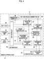
- Fig. 1 shows the configuration of an ultrasound diagnostic apparatus 1 according to Embodiment 1 of the invention.
- the ultrasound diagnostic apparatus 1 comprises a head-mounted display 2 and a diagnostic apparatus body 3, and the head-mounted display 2 and the diagnostic apparatus body 3 are connected in a wireless state.
- the head-mounted display 2 is a display device that is mounted on the head of the user and is viewed by the user who mounts the head-mounted display 2, and as shown in Fig. 2 , has a shape of so-called spectacles.
- the head-mounted display 2 comprises two display units 21A and 21B, and the two display units 21A and 21B are connected by a bridge portion B, and temple portions A are connected to end portions of the two display units 21A and 21B, respectively.
- the bridge portion B is placed and fixed on a nose of the user, and the two temple portions A are placed and fixed on both ears of the user, whereby the head-mounted display 2 is fixed to the head of the subject.
- the two display units 21A and 21B face right and left eyes of the user, respectively.
- a camera unit 22 that has an imaging lens F disposed on a front surface is attached to a connection portion of the left display unit 21B and the temple portion A as viewed from the user who mounts the head-mounted display 2.
- An accommodation portion D where various circuits necessary for the operation of the head-mounted display 2, a battery, and the like are accommodated is disposed in the temple portion A connected to the right display unit 21A.
- Fig. 3 shows the configuration of the head-mounted display 2.
- the head-mounted display 2 has a head-mounted display-side wireless communication unit 23, and the camera unit 22, a communication controller 24, and a display controller 25 are connected to the head-mounted display-side wireless communication unit 23.
- a display unit 21 is connected to the display controller 25.
- a head-mounted display controller 26 is connected to the camera unit 22, the head-mounted display-side wireless communication unit 23, the communication controller 24, and the display controller 25.
- the two display units 21A and 21B in Fig. 2 are collectively referred to as the display unit 21.
- the communication controller 24, the display controller 25, and the head-mounted display controller 26 configure a head-mounted display processor 27.
- a battery 28 is incorporated in the head-mounted display 2.
- the head-mounted display-side wireless communication unit 23, the head-mounted display processor 27, and the battery 28 are accommodated in the accommodation portion D of the head-mounted display 2.
- the camera unit 22 of the head-mounted display 2 generates a camera image obtained by imaging a field of view in front of the user through the imaging lens F.
- the camera unit 22 incorporates an image sensor that images the field of view in front of the user through the imaging lens F to acquire a camera image signal as an analog signal, an analog signal processing circuit that amplifies the camera image signal acquired by the image sensor to convert the camera image signal to a digital signal, and a digital signal processing circuit that performs various kinds of correction, such as gain correction, on the converted digital signal to generate a camera image.
- the analog signal processing circuit and the digital signal processing circuit can also be incorporated in the head-mounted display processor 27.
- the head-mounted display-side wireless communication unit 23 of the head-mounted display 2 includes an antenna that performs transmission and reception of radio waves, and transmits the camera image generated by the camera unit 22 to the diagnostic apparatus body 3.
- the head-mounted display-side wireless communication unit 23 modulates a carrier based on the camera image to generate a transmission signal representing the camera image and supplies the generated transmission signal to the antenna, and transmits the radio waves from the antenna, thereby transmitting the camera image to the diagnostic apparatus body 3 in a wireless manner.
- a modulation system of the carrier for example, amplitude shift keying (ASK), phase shift keying (PSK), quadrature phase shift keying (QPSK), or 16 quadrature amplitude modulation (16QAM) is used.
- the head-mounted display-side wireless communication unit 23 receives data, such as an ultrasound image transmitted from the diagnostic apparatus body 3, and transmits the received data to the display unit 21 through the display controller 25.
- the head-mounted display-side wireless communication unit 23 receives instruction information and the like for instructing the operation of the head-mounted display 2 from the diagnostic apparatus body 3 and outputs the received instruction information and the like to the head-mounted display controller 26.
- the display unit 21 of the head-mounted display 2 has transmittance to secure the field of view of the user in a state in which the user mounts the head-mounted display 2.
- the display unit 21 is a display that displays data, such as an ultrasound image transmitted from the diagnostic apparatus body 3.
- the display controller 25 of the head-mounted display processor 27 executes predetermined processing on data and the like transmitted from the diagnostic apparatus body 3 and displays the ultrasound image and the like on the display unit 21 under the control of the head-mounted display controller 26.
- the communication controller 24 of the head-mounted display processor 27 performs control such that the head-mounted display-side wireless communication unit 23 transmits the camera image and receives the ultrasound image and the like with transmission and reception field intensity set by the head-mounted display controller 26.
- the head-mounted display controller 26 of the head-mounted display processor 27 performs control of each unit of the head-mounted display 2 based on a program stored in advance, and the instruction information and the like transmitted from the diagnostic apparatus body 3 in a wireless manner.
- the battery 28 of the head-mounted display 2 is incorporated in the head-mounted display 2, and supplies electric power to each circuit of the head-mounted display 2.
- the head-mounted display processor 27 having the communication controller 24, the display controller 25, and the head-mounted display controller 26 is configured with a central processing unit (CPU) and a control program causing the CPU to execute various kinds of processing
- the head-mounted display processor 27 may be configured using a field programmable gate array (FPGA), a digital signal processor (DSP), an application specific integrated circuit (ASIC), a graphics processing unit (GPU), or other integrated circuits (ICs) or may be configured by combining the ICs.
- the communication controller 24, the display controller 25, and the head-mounted display controller 26 can also be configured to be partially or wholly integrated into one CPU or the like.
- the diagnostic apparatus body 3 comprises an ultrasound probe 31 having a transducer array 31A, and a transmission and reception unit 32 is connected to the transducer array 31A.
- a transmission and reception controller 33 and an ultrasound image generation unit 34 are connected to the transmission and reception unit 32, and a body-side wireless communication unit 35 is connected to the ultrasound image generation unit 34.
- a communication controller 36 and a navigation image generation unit 37 are connected to the body-side wireless communication unit 35.
- a measurement spot decision unit 38, a measurement procedure association unit 39, and a ground derivation unit 40 are connected to the navigation image generation unit 37.
- the measurement procedure association unit 39 and the ground derivation unit 40 are connected to the measurement spot decision unit 38.
- a body controller 41 is connected to the transmission and reception controller 33, the ultrasound image generation unit 34, the communication controller 36, the navigation image generation unit 37, the measurement spot decision unit 38, the measurement procedure association unit 39, and the ground derivation unit 40.
- An input device 42, a storage unit 43, and a data memory 44 are connected to the body controller 41.
- the body controller 41 and the storage unit 43, and the body controller 41 and the data memory 44 are connected to transfer information in two directions.
- the transmission and reception unit 32, the transmission and reception controller 33, the ultrasound image generation unit 34, the communication controller 36, the navigation image generation unit 37, the measurement spot decision unit 38, the measurement procedure association unit 39, the ground derivation unit 40, and the body controller 41 configure a body processor 45.
- the transducer array 31A of the ultrasound probe 31 has a plurality of transducers arranged in a one-dimensional or two-dimensional manner. Each transducer transmits an ultrasonic wave in response to a drive signal supplied from the transmission and reception unit 32, receives an ultrasound echo from a subject, and outputs a signal based on the ultrasound echo.
- Each transducer is configured by forming electrodes at both ends of a piezoelectric body made of, for example, piezoelectric ceramic represented by lead zirconatetitanate (PZT), a polymer piezoelectric element represented by poly vinylidene di fluoride (PVDF), piezoelectric single crystal represented by lead magnesium niobate-lead titanate (PMN-PT), or the like.
- PZT lead zirconatetitanate
- PVDF polymer piezoelectric element represented by poly vinylidene di fluoride
- PMN-PT piezoelectric single crystal represented by lead magnesium niobate-lea
- the transmission and reception controller 33 of the body processor 45 controls transmission and reception of ultrasonic waves by the transducer array 31A of the ultrasound probe 31 in a given observation mode and under a given transmission and reception condition.
- the observation mode indicates a mode for generating a so-called B mode (Brightness mode) image, a mode for generating a Doppler image, and the like.
- the transmission and reception condition includes a gain of a signal in the transmission and reception unit 32, a dynamic range, a transmission focus position of an ultrasonic wave in the ultrasound image generation unit 34, a reception focus position, a display depth of an ultrasound image, and the like described below.
- the transmission and reception unit 32 of the body processor 45 makes the transducer array 31A perform transmission and reception of ultrasonic waves under the control of the transmission and reception controller 33. As shown in Fig. 5 , the transmission and reception unit 32 is configured with a transmission unit 51 and a reception unit 52.
- the transmission unit 51 of the transmission and reception unit 32 includes, for example, a plurality of pulse generators, and adjusts a delay amount of each drive signal based on a transmission delay pattern selected in response to a control signal from the transmission and reception controller 33 such that the ultrasonic waves transmitted from a plurality of transducers of the transducer array 31A form an ultrasonic beam, and supplies the drive signals to a plurality of transducers.
- a pulsed or continuous-wave voltage is applied to the electrodes of each of a plurality of transducers of the transducer array 31A, the piezoelectric body expands and contracts, and a pulsed or continuous-wave ultrasonic wave is generated from each of the transducers.
- An ultrasonic beam is formed from a combined wave of the ultrasonic waves.
- the transmitted ultrasonic beam is reflected by, for example, a target, such as a part of the subject, and propagates toward the transducer array 31A of the ultrasound probe 31.
- the ultrasonic wave propagating toward the transducer array 31A is received by each transducer configuring the transducer array 31A.
- each transducer configuring the transducer array 31A expands and contracts with reception of the propagating ultrasound echo to generate an electrical signal, and outputs the electrical signal to the reception unit 52.
- the reception unit 52 of the transmission and reception unit 32 executes processing of the signal output from the transducer array 31A in response to a control signal from the transmission and reception controller 33. As shown in Fig. 5 , the reception unit 52 has an amplification unit 53 and an analog-digital (AD) conversion unit 54.
- AD analog-digital
- the amplification unit 53 amplifies the signal input from each transducer configuring the transducer array 31A and transmits the amplified signal to the AD conversion unit 54.
- the AD conversion unit 54 converts the signal transmitted from the amplification unit 53 into digital data, and transmits the converted data to the ultrasound image generation unit 34. In this case, for example, the amplification unit 53 amplifies the signal with a given gain, and the AD conversion unit 54 converts the signal into digital data with a given dynamic range.
- the ultrasound image generation unit 34 of the body processor 45 generates various ultrasound images based on the signal transmitted from the transmission and reception unit 32. As shown in Fig. 6 , the ultrasound image generation unit 34 includes a B mode image generation unit 56 and a Doppler image generation unit 57.
- the B mode image generation unit 56 executes so-called reception focus processing by giving a delay to each piece of data converted by the AD conversion unit 54 in compliance with a sound speed or a distribution of the sound speed set based on a reception delay pattern selected in response to a control signal from the transmission and reception controller 33 and performing additions.
- reception focus processing each piece of data converted by the AD conversion unit 54 is subjected to phasing addition, and a sound ray signal with a narrowed focus of the ultrasound echo is acquired.
- the B mode image generation unit 56 performs correction of attenuation due to a propagation distance depending on a depth of a reflection position of the ultrasonic wave on the acquired sound ray signal, and then, executes envelope detection processing to generate a B mode image that is tomographic image information regarding a tissue in the subject.
- the B mode image generation unit 56 converts (raster-converts) the generated B mode image to an image compliant with a normal television signal scanning system, executes various kinds of necessary image processing, such as gradation processing, on the converted B mode image, and then, sends the B mode image to the body-side wireless communication unit 35.
- the Doppler image generation unit 57 generates a Doppler image using a color Doppler method, for example.
- the Doppler image generation unit 57 performs frequency analysis on data converted by the AD conversion unit 54 to calculate a Doppler shift frequency and acquires information regarding a movement speed of a tissue in the subject as Doppler data.
- the Doppler image generation unit 57 converts each piece of Doppler data of each tissue in the subject into color information corresponding to the movement speed of the tissue and performs raster-conversion into an image compliant with a normal television signal scanning system, thereby generating a so-called color Doppler image (Doppler image).
- the Doppler image generation unit 57 executes various kinds of necessary image processing, such as gradation processing, on the generated Doppler image and superimposes the Doppler image on which the image processing is executed, on the corresponding B mode image.
- the body-side wireless communication unit 35 of the diagnostic apparatus body 3 includes an antenna that performs transmission and reception of radio waves, and modulates a carrier based on the ultrasound image generated in the ultrasound image generation unit 34 to generate a transmission signal representing the ultrasound image.
- the body-side wireless communication unit 35 supplies the transmission signal representing the ultrasound image generated in this manner to the antenna and transmits the radio waves from the antenna, thereby sequentially transmitting the ultrasound images to the head-mounted display 2 in a wireless manner.
- ASK, PSK, QPSK, 16QAM, or the like is used as a modulation system of the carrier.
- the body-side wireless communication unit 35 receives the camera image from the head-mounted display 2.
- the communication controller 36 of the body processor 45 performs control such that the body-side wireless communication unit 35 performs transmission and reception of various kinds of data with transmission field intensity and reception field intensity set by the body controller 41.
- the input device 42 of the diagnostic apparatus body 3 is provided for the user to perform an input operation, and can comprise a keyboard, a mouse, a trackball, a touch pad, a touch panel, a microphone, and the like.
- the data memory 44 is a memory that stores subject information as information regarding the subject on which ultrasonography is to be performed and data regarding ultrasonography, such as a result of ultrasonography on the subject. For example, data regarding ultrasonography can be saved in the data memory 44 by an input operation of the user through the input device 42. For example, data regarding ultrasonography can be extracted from the data memory 44 by an input operation of the user through the input device 42.
- a recording medium such as a flash memory, a hard disc drive (HDD), a solid state drive (SSD), a flexible disc (FD), a magneto-optical disc (MO disc), a magnetic tape (MT), a random access memory (RAM), a compact disc (CD), a digital versatile disc (DVD), a secure digital card (SD card), or a universal serial bus memory (USB memory), a server, or the like can be used.
- a flash memory such as a flash memory, a hard disc drive (HDD), a solid state drive (SSD), a flexible disc (FD), a magneto-optical disc (MO disc), a magnetic tape (MT), a random access memory (RAM), a compact disc (CD), a digital versatile disc (DVD), a secure digital card (SD card), or a universal serial bus memory (USB memory), a server, or the like
- HDD hard disc drive
- SSD solid state drive
- FD flexible disc
- MO disc magneto-optical disc
- MT magnetic
- the measurement spot decision unit 38 of the body processor 45 decides a measurement spot of the subject where transmission and reception of the ultrasonic wave by the ultrasound probe 31 is desired, that is, a measurement spot of the subject where the ultrasound probe 31 should be positioned at the time of ultrasonography, based on the input subject information.
- the measurement spot decision unit 38 sends information regarding the decided measurement spot to the navigation image generation unit 37.
- the subject information that is input by the user through the input device 42 can include at least one of a medical history of the subject, a status of treatment of the subject, such as follow-up and a status of adverse reaction of ingestion, a health status of the subject, such as whether or not the subject is confined to a bed and a risk factor by a blood test, or physical information, such as the sex, age, and weight of the subject, in addition to at least one of the symptom or the disease of the subject.
- Such subject information can be input, for example, text data, voice data, or the like input by the user through the input device 42.
- the subject information can also be input by the user selecting a previous diagnostic result and the like of the subject stored in the data memory 44 through the input device 42.
- the measurement spot decision unit 38 In deciding the measurement spot of the subject, the measurement spot decision unit 38 first estimates a part in the subject related to at least one of the symptom or the disease of the subject and a status of the part based on the input subject information, and decides the measurement spot of the subject based on the estimated part in the subject and the estimated status of the part.
- the status of the part estimated by the measurement spot decision unit 38 corresponds to a viewpoint in deciding the measurement spot of the subject, and includes, for example, a disease name of the estimated part, a status of the estimated part, such as bleeding, and a size and a shape of the estimated part.
- the measurement spot decision unit 38 stores, for example, a measurement spot correspondence table in which a symptom of the subject, a part in the subject, a status of the part in the subject, and candidates of a measurement spot of the subject correspond to one another.
- the measurement spot correspondence table may be stored at another place in the diagnostic apparatus body 3. Referring to the measurement spot correspondence table, the part in the subject and the status of the part can be estimated from the symptom or the disease of the subject to decide the measurement spot of the subject.
- the measurement spot decision unit 38 can estimate "right kidney” as a part in the subject related to "dull pain in right side” with reference to the measurement spot correspondence table and can estimate a disease name "renal calculus” as a status of "right kidney”.
- the measurement spot decision unit 38 can decide "right side” as a measurement spot of the subject based on information of estimated "right kidney” and "renal calculus” with reference to the measurement spot correspondence table.
- the measurement spot correspondence table for example, in addition to corresponding the symptom of the subject, the part in the subject, the status of the part in the subject, and the candidates of the measurement spot of the subject to one another, a medical history, a status of treatment, a health status, and physical information of the subject as information included in the subject information can also correspond to one another.
- the measurement spot decision unit 38 can estimate a more appropriate part in the subject and a status of the part and can decide a more appropriate measurement spot with respect to the symptom or the disease of the subject.
- the measurement procedure association unit 39 of the body processor 45 sends the measurement procedure to the navigation image generation unit 37 in association with the estimated part in the subject and the estimated status of the part.
- the measurement procedure association unit 39 stores a measurement procedure association table in which given measurement procedures are associated with a plurality of parts in the subject estimatable by the measurement spot decision unit 38 and statuses of a plurality of parts, and can associate a measurement procedure with a part in the subject and a status of the part referring to the measurement procedure association table.
- a measurement procedure that "a color Doppler image is acquired after a B mode image is acquired” can be associated with a combination of "right kidney” and "renal calculus”.
- the ground derivation unit 40 of the body processor 45 derives a description to be a ground for the decision of the measurement spot of the subject by the measurement spot decision unit 38 from the subject information received through the measurement spot decision unit 38 and sends the derived description to be the ground to the navigation image generation unit 37.
- the description to be the ground for the decision of the measurement spot includes, for example, symptoms, such as pain, discomfort, vomiting, eruption, swelling, and bleeding, diseases, such as cancer, tumor, inflammation, heart disease, calculus, and complication, a status of treatment, such as follow-up, post-operative confirmation, adverse reaction of ingestion, and recrudescence of symptoms, a possibility of a uterine disease in a case of female, description regarding physical information of the subject, such as a disease easily caused by aging and a disease easily caused by obesity, symptoms due to being confined to a bed, symptoms due to failure to dietary restriction, symptoms caused by fatigue, onset of a disease estimated by a risk factor from a blood test, and a possibility of internal bleeding by a traffic accident.
- symptoms such as pain, discomfort, vomiting, eruption, swelling, and bleeding
- diseases such as cancer, tumor, inflammation, heart disease, calculus, and complication
- a status of treatment such as follow-up, post-operative confirmation, adverse reaction of ingestion, and recrudescence of symptoms
- the ground derivation unit 40 can derive the description to be the ground for the decision of the measurement spot by extracting a keyword related to the measurement spot decided by the measurement spot decision unit 38, and the estimated part in the subject and the estimated status of the part from the subject information input by the user through the input device 42, for example.
- the ground derivation unit 40 can also derive the description to be the ground for the decision of the measurement spot by an inference based on the extracted keyword, for example.
- the navigation image generation unit 37 of the body processor 45 recognizes the subject shown in the camera image received from the head-mounted display 2 through the body-side wireless communication unit 35 and generates a navigation image indicating a position of the measurement spot decided by the measurement spot decision unit 38 with respect to the recognized subject.
- the navigation image generation unit 37 transmits the generated navigation image to the head-mounted display 2 through the body-side wireless communication unit 35 and displays the navigation image on the display unit 21 of the head-mounted display 2.
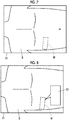
- a measurement spot mark M that is positioned in the right side as the measurement spot of the subject S and is represented by a rectangularly closed broken line is shown as an example of a navigation image.
- the rectangularly closed broken line representing the measurement spot mark M represents a position and a direction of the ultrasound probe 31 that should be brought into contact with the measurement spot.
- the user views the subject S through the transmissive display unit 21 of the head-mounted display 2, and the measurement spot mark M is displayed on the display unit 21 to overlap the right side of the subject S viewed by the user.
- the navigation image generation unit 37 can include, in the navigation image, the part of the subject and the status of the part used in the decision of the measurement spot by the measurement spot decision unit 38, information representing the measurement procedure associated with the part in the subject S and the status of the part by the measurement procedure association unit 39, and information representing the description of the ground derived by the ground derivation unit 40.
- the navigation image generation unit 37 can include, in the guide panel G1, the measurement spot mark M and a guide panel G1 connected to the measurement spot mark M in the navigation image, and can include text data representing a name of the part in the subject, text data representing the status of the part in the subject, text data (not shown) representing the measurement procedure, and text data (not shown) representing the description of the ground.
- the storage unit 43 of the diagnostic apparatus body 3 stores an operation program of the diagnostic apparatus body 3, and the like.
- a recording medium such as a flash memory, an HDD, an SSD, an FD, an MO disc, an MT, a RAM, a CD, a DVD, an SD card, or a USB memory, a server, or the like can be used.
- the body controller 41 of the body processor 45 performs control of each unit of the diagnostic apparatus body 3 based on a program stored in advance in the storage unit 43 or the like, and an input operation of the user through the input device 42.
- the body processor 45 having the transmission and reception unit 32, the transmission and reception controller 33, the ultrasound image generation unit 34, the communication controller 36, the navigation image generation unit 37, the measurement spot decision unit 38, the measurement procedure association unit 39, the ground derivation unit 40, and the body controller 41 is configured with a CPU and a control program causing the CPU to execute various kinds of processing
- the body processor 45 may be configured using an FPGA, a DSP, an ASIC, a GPU, or other ICs or may be configured by combining the ICs.
- the transmission and reception unit 32, the transmission and reception controller 33, the ultrasound image generation unit 34, the communication controller 36, the navigation image generation unit 37, the measurement spot decision unit 38, the measurement procedure association unit 39, the ground derivation unit 40, and the body controller 41 of the body processor 45 can also be configured to be partially or wholly integrated into one CPU or the like.
- subject information including at least one of a symptom or a disease of the subject S is input by the user through the input device 42 of the diagnostic apparatus body 3.
- the subject information can be input as text data, voice data, or the like input by the user through the input device 42, for example.
- the subject information can also be input by the user selecting a previous diagnostic result and the like of the subject S stored in the data memory 44 through the input device 42.
- the measurement spot decision unit 38 of the diagnostic apparatus body 3 estimates the part of the subject S and the status of the part related to any one of the symptom and the disease of the subject S from the input subject information and decides the measurement spot of the subject S based on the estimated part in the subject S and the estimated status of the part.
- the measurement spot decision unit 38 can store the measurement spot correspondence table in which, for example, the symptom of the subject S, the part in the subject S related to the symptom, the status of the part in the subject S, and the measurement spot of the subject S correspond to one another, can estimate the part in the subject S and the status of the part from the subject information referring to the measurement spot correspondence table, and can decide the measurement spot of the subject S based on the estimated part in the subject S and the estimated status of the part.
- the measurement spot of the subject S is automatically decided by the measurement spot decision unit 38 from the subject information input by the user through the input device 42, and thus, an appropriate measurement spot with respect to a symptom or a disease of the subject S is decided regardless of user's proficiency.
- the measurement procedure association unit 39 of the diagnostic apparatus body 3 sends the measurement procedure to the navigation image generation unit 37 in association with the estimated part in the subject and the estimated status of the part.
- the measurement procedure association unit 39 can store a measurement procedure association table in which, for example, a given measurement procedure is associated with each of a plurality of parts in the subject and the statuses of a plurality of parts estimatable by the measurement spot decision unit 38 and can associate the measurement procedure with the part in the subject and the status of the part referring to the measurement procedure association table.
- the ground derivation unit 40 of the diagnostic apparatus body 3 derives a description to be a ground for the decision of the measurement spot of the subject by the measurement spot decision unit 38 from the subject information received through the measurement spot decision unit 38 and sends the derived description to be the ground to the navigation image generation unit 37.
- the ground derivation unit 40 can derive the description to be the ground for the decision of the measurement spot by extracting a keyword related to the measurement spot decided by the measurement spot decision unit 38, and the estimated part in the subject and the estimated status of the part from the subject information input by the user through the input device 42, for example.
- the ground derivation unit 40 can also derive the description to be the ground for the decision of the measurement spot by an inference based on the extracted keyword, for example.
- a camera image obtained by imaging the subject S positioned within a field of view in front of the user is captured by the camera unit 22 of the head-mounted display 2 mounted on the head of the user.
- the camera image acquired in this manner is transmitted to the diagnostic apparatus body 3 through the head-mounted display-side wireless communication unit 23 in a wireless manner.
- the camera image transmitted from the head-mounted display 2 in a wireless manner is sent to the navigation image generation unit 37 of the diagnostic apparatus body 3 through the body-side wireless communication unit 35.
- the navigation image generation unit 37 recognizes the subject shown in the camera image received from the head-mounted display 2 through the body-side wireless communication unit 35 and generates a navigation image indicating a position of the measurement spot decided by the measurement spot decision unit 38 with respect to the recognized subject.
- the navigation image generation unit 37 can include information representing the measurement procedure associated with the part in the subject S and the status of the part by the measurement procedure association unit 39 and information representing the description of the ground derived by the ground derivation unit 40, in the navigation image as shown in Fig. 8 .
- the navigation image includes the measurement spot mark M positioned at the measurement spot of the subject S and the guide panel G1.
- text data (not shown) representing the measurement procedure and text data (not shown) representing the description of the ground are included.
- the navigation image generation unit 37 can recognize the subject by storing typical pattern data of the subject as a template in advance, calculating a degree of similarity to pattern data while searching the inside of the camera image with the template, and considering that the subject is present at a place where the degree of similarity is equal to or greater than a threshold value and is the maximum.
- a threshold value for example, a machine learning method described in Csurka et al.: Visual Categorization with Bags of Keypoints, Proc. of ECCV Workshop on Statistical Learning in Computer Vision, pp.
- the navigation image generated in this manner is transmitted to the head-mounted display 2 through the body-side wireless communication unit 35 in a wireless manner.
- the navigation image transmitted from the diagnostic apparatus body 3 in a wireless manner is sent to the display controller 25 through the head-mounted display-side wireless communication unit 23 and is displayed on the display unit 21 of the head-mounted display 2, for example, as shown in Fig. 8 under the control of the display controller 25.
- the navigation image including the measurement spot mark M and the guide panel G1 is displayed on the display unit 21 to overlap the subject S viewed by the user through the transmissive display unit 21.
- the user brings the ultrasound probe 31 into contact with a body surface of the subject S such that the position and the direction of the ultrasound probe 31 match the measurement spot of the subject S shown in the navigation image displayed on the display unit 21, and performs ultrasonography of the subject S.
- the measurement spot of the subject S where the transmission and reception of the ultrasonic wave by the ultrasound probe 31 is desired is displayed on the display unit 21 of the head-mounted display 2, and thus, the user can easily recognize the measurement spot of the subject S.
- the user can easily recognize the measurement procedure for measuring the part in the subject S and the status of the part related to the measurement spot and the description of the ground for the decision of the measurement spot, and thus, the user can easily perform ultrasonography of the subject S.
- the ultrasound diagnostic apparatus 1 ends the operation to display the measurement spot of the subject S on the display unit 21 of the head-mounted display 2.
- the measurement spot of the subject S is automatically decided based on the subject information input by the user through the input device 42 of the diagnostic apparatus body 3, and the decided measurement spot is displayed on the display unit 21 of the head-mounted display 2. Therefore, it is possible to allow the user to easily perform ultrasonography on the subject S regardless of user's proficiency.
- the measurement spot decision unit 38 decides the measurement spot of the subject S based on the subject information, such as text data or voice data input from the user through the input device 42 or a previous diagnostic result of the subject S stored in the data memory 44
- the measurement spot decision unit 38 can also extract a keyword related to at least one of the symptom or the disease of the subject from the subject information and decide a measurement spot of the subject S based on the extracted keyword. With this, even though information unrelated to the symptom or the disease of the subject S is included in the subject information, only information necessary for deciding the measurement spot of the subject S is extracted, and thus, the measurement spot decision unit 38 can decide a more appropriate measurement spot with respect to the symptom or the disease of the subject S.
- the measurement spot decision unit 38 estimates the part in the subject S and the status of the part related to at least one of the symptom or the disease of the subject S from the subject information including at least one of the symptom or the disease of the subject S referring to the measurement spot correspondence table.
- the part in the subject S and the status of the part can also be estimated using a method of so-called deep learning.
- the measurement spot decision unit 38 decides the measurement spot of the subject S based on the subject information including at least one of the symptom or the disease of the subject S
- the measurement spot decision unit 38 can also decide the measurement spot of the subject S, for example, based on at least one of a medical history, a status of treatment, a health status, or physical information of the subject S.
- the measurement spot decision unit 38 can decide a more accurate measurement spot, for example, in a case where a symptom with high urgency, such as bleeding, appears in the subject S.
- the measurement spot decision unit 38 can send, for example, text data representing the measurement spot, an image in which a mark representing the measurement spot, such as a body mark, is disposed on a general two-dimensional human model, or an image in which a mark representing the measurement spot is disposed on a general three-dimensional human model, as information representing the measurement spot of the subject S to the navigation image generation unit 37. Even though information representing the measurement spot is received in any format from the measurement spot decision unit 38, the navigation image generation unit 37 can generate a navigation image indicating the measurement spot.
- the measurement spot decision unit 38 can store a given degree of urgency with respect to each of a plurality of estimatable parts in the subject S and the statuses of a plurality of parts, and can send the degree of urgency corresponding to the part in the subject S and the status of the part estimated from the subject information to the navigation image generation unit 37.
- the degree of urgency of the part is set to be higher.
- a degree of urgency of a status in which the part in the subject S is calcified is set to be lower than a degree of urgency of a status in which the part in the subject S is bleeding.
- the navigation image generation unit 37 can include information representing the degree of urgency of the part in the subject S and the status of the part related to the decided measurement spot, in the navigation image.
- the navigation image can include a mark, text data, or the like representing the degree of urgency.
- the measurement spot mark M indicating the measurement spot, or the like may have a given color representing the degree of urgency.
- the navigation image includes the measurement spot mark M represented by the rectangularly closed broken line as indicating the measurement spot of the subject S
- the shape and the size of the measurement spot mark M are not limited thereto.
- the measurement spot mark M may have a circular shape or a polygonal shape or may be any closed curved shape.
- the measurement spot mark M is not limited as being formed with the broken line, and can also be formed with a solid line or can also be formed with a region colored with a given color.
- the navigation image can also include an arrow P shown in Fig. 9 instead of the measurement spot mark M.
- a navigation image includes a guide panel G2 that is connected to a based end of the arrow P and indicates "right side" as the name of the measurement spot.
- the measurement spot decision unit 38 estimates the part in the subject S and the status of the part from the input subject information, and decides the measurement spot of the subject S based on the estimated part in the subject S and the estimated status of the part
- the same measurement spot may be decided from a plurality of combinations of the part in the subject S and the status of the part.
- the measurement spot decision unit 38 may decide "below solar plexus" as the same measurement spot based on the combination of "gallbladder” and “gallbladder inflammation” and the combination of "pancreas” and “pancreatitis” as the combination of the part in the subject S and the status of the part.
- measurement procedures associated by the measurement procedure association unit 39 and descriptions to be grounds derived by the ground derivation unit 40 may be different.
- the navigation image generation unit 37 can include a plurality of guide panels G3 and G4 in the subject S with respect to one measurement spot in a navigation image.
- the navigation image includes two guide panels G3 and G4 extending from a measurement spot mark M positioned below the solar plexus of the subject S.
- the guide panel G3 includes, for example, text data representing "gallbladder” as a name of a part in the subject S, text data representing "gallbladder inflammation” as a status of "gallbladder”, text data representing a measurement procedure for measuring “gallbladder inflammation”, and text data representing a description to be a ground for the decision of "below solar plexus” as a measurement spot from "gallbladder” and "gallbladder inflammation”.
- the guide panel G4 includes, for example, text data representing "pancreas” as a name of the part in the subject S, text data representing "pancreatitis” as a status of "pancreas”, text data representing a measurement procedure for measuring "pancreatitis”, and text data representing a description to be a ground for the decision of "below solar plexus” as a measurement spot from "pancreas” and "pancreatitis”.
- the navigation image includes information related to a plurality of parts in the subject S and the statuses of a plurality of parts with respect to one measurement spot, whereby the user can easily recognize a plurality of parts in the subject S and the statuses of a plurality of parts related to the symptom or the disease of the subject S with respect to the one measurement spot and can perform appropriate measurement.
- the navigation image generation unit 37 can consider one measurement spot as a plurality of independent measurement spots related to a plurality of parts in the subject S and the statuses of a plurality of parts, such as "below solar plexus” related to "gallbladder” and “below solar plexus” related to "pancreas", for example, and can include the measurement spot marks M or the like indicating the measurement spots in the navigation image. For example, as shown in Fig.
- the navigation image generation unit 37 can include a measurement spot mark M3 indicating "below solar plexus” regarding "gallbladder” and a measurement spot mark M4 indicating "below solar plexus” regarding "pancreas” in the navigation image.
- the measurement spot mark M3 and the measurement spot mark M4 are disposed to partially overlap each other.
- the navigation image includes a guide panel G3 that is connected to the measurement spot mark M3 and includes text data representing "gallbladder”, and a guide panel G4 that is connected to the measurement spot mark M4 and includes text data representing "pancreas”.
- the guide panel G3 is disposed to partially overlap the guide panel G4, for example, the navigation image generation unit 37 can replace a vertical relationship between the guide panel G3 and the guide panel G4 based on an input operation of the user through the input device 42.
- the navigation image includes information representing the measurement procedures associated by the measurement procedure association unit 39 and information representing the descriptions to be the grounds for the decision of the measurement spots derived by the ground derivation unit 40 in the guide panels G1, G3, and G4, information representing the measurement procedures and information representing the descriptions to be the grounds for the decision of the measurement spots are not limited as being included in the guide panels G1, G3, and G4.
- the navigation image can position a list of information representing the measurement procedures and the descriptions to be the grounds for the decision of the measurement spots near the measurement spots instead of the guide panels G1, G3, and G4.
- the diagnostic apparatus body 3 has the data memory 44 that is connected to the body controller 41 and stores the subject information
- an external server that is connected to an external network, such as a network in a hospital, and stores an electronic medical chart and the like of a subject can also be connected to the body controller 41.
- the user can input the electronic medical chart and the like of the subject stored in the external server as subject information to the body controller 41 by an input operation through the input device 42.
- the display unit 21 of the head-mounted display 2 may not have transmittance.
- the camera unit 22 and the display controller 25 are connected, and the camera image acquired by the camera unit 22 is displayed on the display unit 21 of the head-mounted display 2, whereby the user can view the field of view in front of the user displayed on the display unit 21.
- the navigation image generation unit 37 can include the camera image in the navigation image, for example, by generating an image in which the measurement spot mark M shown in Fig. 7 is superimposed on the camera image, as a navigation image.
- the display unit 21 of the head-mounted display 2 does not have transmittance, similarly to a case where the display unit 21 has transmittance, the user can easily recognize the measurement spot of the subject S. Therefore, it is possible to allow the user to easily perform ultrasonography on the subject S regardless of proficiency.
- the ultrasound image generation unit 34 can further have an M mode image generation unit that generates a so-called M mode image, an elastic map image generation unit that generates a so-called elastic map image, a sound speed map image generation unit that generates a so-called sound speed map image, and the like.
- the ultrasound diagnostic apparatus 1 can have a mode where the M mode image is generated, a mode where the elastic map image is generated, a mode where the sound speed map image is generated, and the like, in addition to a mode where the B mode image is generated and a mode where the Doppler image is generated.
- the ultrasound diagnostic apparatus 1 has a plurality of observation modes, with the ultrasound diagnostic apparatus 1 of Embodiment 1 of the invention, an appropriate measurement spot is decided based on the subject information. Therefore, it is possible to allow the user to easily perform ultrasonography of the subject S regardless of user's proficiency.
- the diagnostic apparatus body 3 can be configured as a stationary apparatus, such as a so-called tower type, or can also be configured as a portable apparatus, such as a so-called tablet type or a laptop type. In this way, the form of the diagnostic apparatus body 3 is not particularly limited.
- the head-mounted display 2 and the diagnostic apparatus body 3 are connected in a wireless state, so-called wired connection may be made.
- the ultrasound probe 31 and the body processor 45 can also be connected in a wireless state.
- the body processor 45 of the diagnostic apparatus body 3 includes the transmission and reception unit 32, the transmission and reception controller 33, and the ultrasound image generation unit 34, the transmission and reception unit 32, the transmission and reception controller 33, and the ultrasound image generation unit 34 can be included in the ultrasound probe 31, instead of being included in the body processor 45.
- the transmission and reception unit 32, the transmission and reception controller 33, and the ultrasound image generation unit 34 included in the ultrasound probe 31 configure a probe processor (not shown).
- the ultrasound image generated by the ultrasound image generation unit 34 of the ultrasound probe 31 is transmitted to the head-mounted display 2, for example, through the body-side wireless communication unit 35 in a wireless manner.
- the body processor 45 of the diagnostic apparatus body 3 includes the navigation image generation unit 37, the measurement spot decision unit 38, the measurement procedure association unit 39, and the ground derivation unit 40
- the navigation image generation unit 37, the measurement spot decision unit 38, the measurement procedure association unit 39, and the ground derivation unit 40 can be included in the head-mounted display processor 27 of the head-mounted display 2, instead of being included in the body processor 45.
- the subject information input by the user through the input device 42 is transmitted to the head-mounted display 2 through the body-side wireless communication unit 35 in a wireless manner, and the subject information transmitted in a wireless manner is received by the measurement spot decision unit 38 of the head-mounted display processor 27 through the head-mounted display-side wireless communication unit 23.
- the measurement spot decision unit 38 decides a measurement spot of the subject S based on the received subject information, and information representing the decided measurement spot is sent to the navigation image generation unit 37.
- the navigation image generation unit 37 generates a navigation image indicating the measurement spot of the subject S based on information representing the measurement spot of the subject S received from the measurement spot decision unit 38 and the camera image acquired by the camera unit 22.
- the navigation image generated in this manner is displayed on the display unit 21 of the head-mounted display 2 through the display controller 25.
- the head-mounted display processor 27 of the head-mounted display 2 includes the navigation image generation unit 37, the measurement spot decision unit 38, the measurement procedure association unit 39, and the ground derivation unit 40, similarly to a case where the body processor 45 of the diagnostic apparatus body 3 includes the navigation image generation unit 37, the measurement spot decision unit 38, the measurement procedure association unit 39, and the ground derivation unit 40, the navigation image indicating the measurement spot of the subject S is generated, and the generated navigation image is displayed on the display unit 21 of the head-mounted display 2. Therefore, it is possible to allow the user to easily perform ultrasonography on the subject S regardless of user's proficiency.
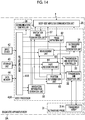
- the transmission and reception unit 32, the transmission and reception controller 33, the ultrasound image generation unit 34, the navigation image generation unit 37, the measurement spot decision unit 38, the measurement procedure association unit 39, the ground derivation unit 40, the input device 42, the storage unit 43, and the data memory 44 provided in the diagnostic apparatus body 3 can be provided in the head-mounted display 2, and the diagnostic apparatus body 3 can be omitted.
- the head-mounted display processor is configured with the communication controller 24, the display controller 25, the head-mounted display controller 26, the transmission and reception unit 32, the transmission and reception controller 33, the ultrasound image generation unit 34, the navigation image generation unit 37, the measurement spot decision unit 38, the measurement procedure association unit 39, and the ground derivation unit 40.
- the input device 42, the storage unit 43, and the data memory 44 are connected to the head-mounted display controller 26.
- a microphone is used as the input device 42.
- the head-mounted display 2 and the ultrasound probe 31 are connected by wireless communication.
- the transmission and reception unit 32, the transmission and reception controller 33, the ultrasound image generation unit 34, the navigation image generation unit 37, the measurement spot decision unit 38, the measurement procedure association unit 39, the ground derivation unit 40, the input device 42, the storage unit 43, and the data memory 44 are provided in the head-mounted display 2
- a measurement spot of the subject S is decided by the measurement spot decision unit 38 based on the subject information input by the user through the input device 42 of the head-mounted display 2
- information representing the decided measurement spot of the subject S is sent to the navigation image generation unit 37.
- the navigation image generation unit 37 generates a navigation image based on information representing the measurement spot of the subject S and the camera image acquired by the camera unit 22.
- the generated navigation image is displayed on the display unit 21 of the head-mounted display 2 through the display controller 25.
- the transmission and reception unit 32 of the head-mounted display 2 transmits a drive signal for driving the transducer array 31A of the ultrasound probe 31 to the ultrasound probe 31 through the head-mounted display-side wireless communication unit 23, and receives a reception signal acquired by the transmission and reception of the ultrasonic wave to and from the subject by the ultrasound probe, through the head-mounted display-side wireless communication unit 23.
- the transmission and reception unit 32 executes various kinds of processing on the received reception signal to generate digital data.
- the ultrasound image generation unit 34 generates an ultrasound image based on the digital data generated by the transmission and reception unit 32, and the generated ultrasound image is displayed on the display unit 21 of the head-mounted display 2 through the display controller 25.
- the head-mounted display 2 comprises the transmission and reception unit 32, the transmission and reception controller 33, the ultrasound image generation unit 34, the navigation image generation unit 37, the measurement spot decision unit 38, the measurement procedure association unit 39, the ground derivation unit 40, the input device 42, the storage unit 43, and the data memory 44, and the diagnostic apparatus body 3 is omitted, similarly to a case where the diagnostic apparatus body 3 comprises the transmission and reception unit 32, the transmission and reception controller 33, the ultrasound image generation unit 34, the navigation image generation unit 37, the measurement spot decision unit 38, the measurement procedure association unit 39, the ground derivation unit 40, the input device 42, the storage unit 43, and the data memory 44, the navigation image indicating the measurement spot of the subject S is generated, and the generated navigation image is displayed on the display unit 21 of the head-mounted display 2. Therefore, it is possible to allow the user to easily perform ultrasonography on the subject S regardless of user's proficiency.
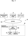
- the ultrasound probe 31 can comprise the transmission and reception unit 32, the transmission and reception controller 33, and the ultrasound image generation unit 34
- the head-mounted display 2 can comprise the navigation image generation unit 37, the measurement spot decision unit 38, the measurement procedure association unit 39, and the ground derivation unit 40
- the diagnostic apparatus body 3 can be omitted.
- the diagnostic apparatus body 3 comprises the transmission and reception unit 32, the transmission and reception controller 33, the ultrasound image generation unit 34, the navigation image generation unit 37, the measurement spot decision unit 38, the measurement procedure association unit 39, and the ground derivation unit 40
- the navigation image indicating the measurement spot of the subject S is generated, and the generated navigation image is displayed on the display unit 21 of the head-mounted display 2. Therefore, it is possible to allow the user to easily perform ultrasonography on the subject S regardless of user's proficiency.
- the measurement spot decision unit 38 decides one measurement spot based on the input subject information
- the measurement spot decision unit 38 can also decide a plurality of measurement spots.
- the measurement spot decision unit 38 stores a measurement spot correspondence table in which candidates of a plurality of parts in the subject S and candidates of the statuses of a plurality of parts relatable correspond to one symptom, and decides a plurality of measurement spots from the subject information referring to the stored measurement spot correspondence table.
- "right subcostal” can correspond to a combination of “gallbladder” and “gallbladder inflammation” and a combination of “gallbladder” and “gallstone”
- “below solar plexus” can correspond to a combination of “pancreas” and “pancreatitis” and a combination of “pancreas” and “pancreatic cancer”
- “below solar plexus to navel” can correspond to a combination of "abdominal aorta” and "abdominal aortic aneurysm” in the measurement spot correspondence table.
- the measurement spot decision unit 38 can decide each of three candidates of the measurement spot of "right subcostal”, “below solar plexus”, and “below solar plexus to navel” estimated from a plurality of parts in the subject S and the statues of the parts with respect to, for example, the symptoms "abdominal pain” and "back pain", as the measurement spot of the subject S.
- the navigation image generation unit 37 In a case where a plurality of measurement spots are decided by the measurement spot decision unit 38 in this manner, the navigation image generation unit 37 generates a navigation image indicating a plurality of measurement spots.
- the navigation image generation unit 37 can include a measurement spot mark M5 indicating "below solar plexus to navel", measurement spot mark M6 indicating "right subcostal", and a measurement spot mark M7 indicating "below solar plexus", in the navigation image.
- the navigation image generation unit 37 can position a guide panel that includes information representing the part in the subject S and the status of the part estimated by the measurement spot decision unit 38, information representing the measurement procedure associated by the measurement procedure association unit 39, and information representing the description to be the ground for the decision of the measurement spot derived by the ground derivation unit 40, near each of a plurality of measurement spot marks.
- the measurement spot decision unit 38 determines whether a plurality of measurement spots are decided by the measurement spot decision unit 38. If a plurality of measurement spots are decided by the measurement spot decision unit 38, similarly to a case where only one measurement spot is decided by the measurement spot decision unit 38, the user can easily recognize the measurement spot of the subject S to easily perform ultrasonography of the subject S.
- the measurement spot decision unit 38 can decide the measurement spot of the subject S by narrowing down a plurality of derived candidates of the measurement spot to leave candidates of the measurement spot having high relevance with the symptom or the disease of the subject S. For example, in a case where a plurality of symptoms of the subject S are input as subject information, the measurement spot decision unit 38 can give a higher evaluation value to a plurality of candidates of the measurement spot as the number of related symptoms is greater, and can narrow down a plurality of candidates of the measurement spot to leave candidates of the measurement spot where the evaluation value is equal to or greater than a given threshold value.
- the measurement spot decision unit 38 can give, as the evaluation value, three points to the candidates of the measurement spot related to the three symptoms of "abdominal pain", “back pain”, and “fever", two points to the candidates of the measurement spot related to two symptoms of "abdominal pain", “back pain”, and “fever”, and one point to the candidates of the measurement spot related to any one of "abdominal pain", "back pain", and "fever”.
- the measurement spot decision unit 38 can narrow down a plurality of candidates of the measurement spot to leave the candidates of the measurement spot related to two or more symptoms of "abdominal pain", "back pain”, and "fever".
- the measurement spot decision unit 38 narrows down a plurality of candidates of the measurement spot, whereby the user can easily recognize the measurement spot having higher relevance with the symptom or the disease of the subject.
- the measurement spot decision unit 38 can store a degree of urgency to each of a plurality of estimatable parts in the subject S and the estimatable statuses of a plurality of parts, and can give priority to a plurality of measurement spots of the subject S related to the part in the subject S and the status of the part based on the degree of urgency corresponding to the part in the subject S and the status of the part estimated from the subject information. For example, priority of a measurement spot related to a part being bleeding is set to be higher than priority of a measurement spot related to a part being calcified.
- the navigation image generation unit 37 In a case where the measurement spot decision unit 38 gives the priority to a plurality of measurement spots of the subject S, the navigation image generation unit 37 generates a navigation image with a plurality of measurement spots given priority. For example, as shown in Fig. 13 , the navigation image generation unit 37 can dispose numbers N1, N2, and N3 representing priority near respective measurement spots in the navigation image.
- the number N1 representing the first priority is disposed near the measurement spot mark M5 indicating "below solar plexus to navel”
- the number N2 representing the second priority is disposed near the measurement spot mark M6 indicating "right subcostal”
- the number N3 representing the third priority is disposed near the measurement spot mark M7 indicating "below solar plexus”.
- a plurality of measurement spot marks M5 to M7 can also be colored with given colors depending on the priority.
- the navigation image generation unit 37 generates the navigation image with a plurality of measurement spots given priority, whereby the user can easily recognize the priority of a plurality of measurement spots.
- Embodiment 1 although the subject S is recognized from the camera image, and the navigation image indicating the measurement spot with respect to the recognized subject S is generated, the ultrasound probe 31 can be further detected from the camera image, and guidance about ultrasonography can be performed for the user corresponding to the position of the detected ultrasound probe 31.
- a diagnostic apparatus body 3A in Embodiment 3 comprises a navigation information derivation unit 61, a probe detection unit 62, a position determination unit 63, a part recognition unit 64, and a measurement unit 65, and comprises a body controller 41A instead of the body controller 41, compared to the diagnostic apparatus body 3 in Embodiment 1 shown in Fig. 4 .
- the navigation information derivation unit 61 is configured with the measurement spot decision unit 38, the measurement procedure association unit 39, and the ground derivation unit 40, and for description, the measurement spot decision unit 38, the measurement procedure association unit 39, and the ground derivation unit 40 are put together into one unit.
- the navigation information derivation unit 61 is connected to the navigation image generation unit 37.
- the probe detection unit 62 is connected to the body-side wireless communication unit 35, and the navigation image generation unit 37 and the position determination unit 63 are connected to the probe detection unit 62.
- the transmission and reception controller 33, the navigation image generation unit 37, the part recognition unit 64, and the measurement unit 65 are connected to the position determination unit 63.
- the ultrasound image generation unit 34, the transmission and reception controller 33, and the navigation information derivation unit 61 are connected to the part recognition unit 64.
- the ultrasound image generation unit 34 is connected to the measurement unit 65.
- the body controller 41A is connected to the transmission and reception controller 33, the ultrasound image generation unit 34, the communication controller 36, the navigation image generation unit 37, the navigation information derivation unit 61, the probe detection unit 62, the position determination unit 63, the part recognition unit 64, and the measurement unit 65.
- the transmission and reception unit 32, the transmission and reception controller 33, the ultrasound image generation unit 34, the communication controller 36, the navigation image generation unit 37, the body controller 41A, the navigation information derivation unit 61, the probe detection unit 62, the position determination unit 63, the part recognition unit 64, and the measurement unit 65 configure a body processor 45A.
- the navigation information derivation unit 61 of the body processor 45A sends navigation information for guiding the user about ultrasonography of the subject S, such as the measurement spot of the subject S, the part in the subject S and the status of the part related to the measurement spot of the subject S, the measurement procedure related to the measurement spot, and the description to be the ground for the decision of the measurement spot, to the navigation image generation unit 37.
- the navigation information derivation unit 61 includes the measurement spot decision unit 38, the measurement procedure association unit 39, and the ground derivation unit 40.
- the measurement spot decision unit 38 is connected to the measurement procedure association unit 39 and the ground derivation unit 40.
- the probe detection unit 62 of the body processor 45A detects the ultrasound probe 31 from the camera image acquired by the camera unit 22 of the head-mounted display 2.
- the probe detection unit 62 can detect the ultrasound probe 31 from the camera image, for example, by performing so-called template matching or the like.
- the position determination unit 63 of the body processor 45A determines whether or not the position of the measurement spot of the subject S indicated by the navigation image generated by the navigation image generation unit 37 overlaps the position of the ultrasound probe 31 detected by the probe detection unit 62. For example, the position determination unit 63 determines that the position of the measurement spot of the subject S overlaps the position of the ultrasound probe 31 in a case where the measurement spot mark M shown in Fig.
- the probe detection unit 62 overlaps the position of the ultrasound probe 31 detected by the probe detection unit 62 by a given area or more, and determines that the position of the measurement spot of the subject S does not overlap the position of the ultrasound probe 31 in a case where the measurement spot mark M overlaps the position of the ultrasound probe 31 only by less than the given area and in a case where the measurement spot mark M does not completely overlap the position of the ultrasound probe 31.
- the part recognition unit 64 of the body processor 45A recognizes a part in the subject S from the ultrasound image generated by the ultrasound image generation unit 34.
- the part recognition unit 64 can recognize the part in the subject S from the ultrasound image, for example, by performing so-called template matching or the like.
- the position determination unit 63 determines that the position of the measurement spot of the subject S overlaps the position of the ultrasound probe 31, the part recognition unit 64 can automatically recognize a part in the subject S related to the measurement spot where the ultrasound probe 31 is positioned, from the ultrasound image generated by the ultrasound image generation unit 34 at that time.
- the measurement unit 65 of the body processor 45A performs measurement regarding the part in the subject S, for example, the length, the area, and the like of the part in the subject S in the B mode image based on the ultrasound image generated by the ultrasound image generation unit 34.
- the measurement unit 65 can perform measurement regarding the part in the subject S based on an input operation of the user through the input device 42.
- the measurement unit 65 can also automatically perform measurement of the part in the subject S recognized by the part recognition unit 64 under a measurement condition corresponding to the part in the subject S recognized by the part recognition unit 64.
- the measurement unit 65 can automatically measure the diameter of the inferior vena cava from the B mode image generated by the ultrasound image generation unit 34.
- the measurement unit 65 automatically performs measurement of the part in the subject S under the measurement condition corresponding to the part in the subject S recognized by the part recognition unit 64, whereby it is possible to reduce user's labor in ultrasonography.
- the transmission and reception controller 33 can control the transmission and reception of the ultrasonic wave by the transducer array 31A of the ultrasound probe 31 in compliance with the transmission and reception condition and the observation mode corresponding to the measurement spot where the ultrasound probe 31 is positioned.
- the transmission and reception controller 33 can control the transmission and reception of the ultrasonic wave in compliance with the transmission and reception condition and the observation mode corresponding to the measurement spot where the ultrasound probe 31 is positioned, for example, by storing the transmission and reception conditions and the observation modes corresponding to a plurality of measurement spots in advance.
- the transmission and reception controller 33 can also control the transmission and reception of the ultrasonic wave by the transducer array 31A of the ultrasound probe 31 in compliance with the transmission and reception condition and the observation mode corresponding to the part in the subject S recognized by the part recognition unit 64.
- the transmission and reception controller 33 can control the transmission and reception of the ultrasonic wave in compliance with the transmission and reception condition and the observation mode corresponding to the part in the subject S recognized by the part recognition unit 64, for example, by storing the transmission and reception conditions and the observation modes corresponding to a plurality of parts in the subject S estimatable by the measurement spot decision unit 38 in advance.
- the body controller 41A controls each unit of the diagnostic apparatus body 3A to perform the measurement of the subject S in compliance with the measurement procedure related to the measurement spot where the ultrasound probe 31 is positioned and associated with the measurement procedure association unit 39.
- the position determination unit 63 determines that a position of "apex" of the subject S in the navigation image overlaps the position of the ultrasound probe 31, a part in the subject S related to "apex” is “heart", a status of "heart” is "mitral regurgitation", and an associated measurement procedure is "a B mode image is acquired, a color Doppler image is acquired, pulmonary regurgitation area measurement by proximal isovelocity surface area (PISA) method is performed, a Doppler image is acquired by a pulse Doppler method, and a regurgitant flow rate is measured", first, to obtain the B mode image, the body controller 41A makes the transmission and reception controller 33 control the transmission and reception of the ultrasonic wave by the transducer array 31A in compliance with the observation mode for acquiring the B mode image.
- PISA proximal isovelocity surface area
- the B mode image displayed on the display unit 21 of the head-mounted display 2 is so-called freeze-displayed, for example, by the user through the input device 42, and in a case where the freeze-displayed B mode image is saved in the data memory 44 of the diagnostic apparatus body 3A, or the like, the body controller 41A makes the transmission and reception controller 33 control the transmission and reception of the ultrasonic wave by the transducer array 31A to execute the next procedure, that is, in compliance with the observation mode for acquiring the color Doppler image.
- the body controller 41A makes the measurement unit 65 perform measurement of the pulmonary regurgitation area by the so-called PISA method.
- the body controller 41A makes the transmission and reception controller 33 control the transmission and reception of the ultrasonic wave by the transducer array 31A in compliance with the observation mode for acquiring the Doppler image by the so-called pulse Doppler method.
- the body controller 41A makes the measurement unit 65 perform measurement of the regurgitant flow rate based on the freeze-displayed Doppler image.
- the body controller 41A controls each unit of the diagnostic apparatus body 3A to perform measurement of the subject S in compliance with the measurement procedure related to the measurement spot where the ultrasound probe 31 is positioned, whereby it is possible to allow the user to easily perform ultrasonography of the subject S regardless of user's proficiency.
- the navigation image generation unit 37 can generate a navigation image in which a state in which the ultrasound probe 31 is positioned at the measurement spot is highlighted. For example, though not shown, the navigation image generation unit 37 can highlight a state in which the ultrasound probe 31 is positioned at the measurement spot, by coloring the measurement spot mark indicating the measurement spot where the ultrasound probe 31 is positioned, with a given color, in a case where the measurement spot mark is formed with a broken line, changing the broken line to a solid line or the like, or disposing text data representing that the ultrasound probe 31 is positioned, near the measurement spot. With this, the user can more clearly recognize that the ultrasound probe 31 is positioned at the measurement spot.
- the navigation image generation unit 37 can include information representing that the series of measurement is completed at the measurement spot, in the navigation image.
- the navigation image generation unit 37 can include information representing that the series of measurement is completed, in the navigation image by coloring the measurement spot mark indicating the measurement spot where the series of measurement is completed, with a given color, in a case where the measurement spot mark is formed with one closed broken line, changing one close broken line to two closed broken lines, or disposing text data representing that the series of measurement is completed, near the measurement spot.
- the navigation image generation unit 37 can generate a navigation image in which the measurement spot closest to the ultrasound probe 31 detected by the probe detection unit 62 among a plurality of measurement spots is highlighted.
- the ultrasound probe 31 (not shown) is positioned at the measurement spot mark M6 indicating "right subcostal", and while the measurement spot mark M5 indicating "below solar plexus to navel" and the measurement spot mark M7 indicating "below solar plexus” are formed with a closed broken line, the measurement spot mark M6 is formed with a one-dot chain line. With this, the user can clearly recognize the measurement spot closest to the ultrasound probe 31 among a plurality of measurement spots.
- the navigation image generation unit 37 can include only information representing the part in the subject S and the status of the part related to the measurement spot closest to the ultrasound probe 31 detected by the probe detection unit 62 among a plurality of measurement spots, information representing the measurement procedure, and information representing the description to be the ground for the decision of the measurement spot, in the navigation image.
- information representing the part in the subject S and the status of the part related to the measurement spot closest to the ultrasound probe 31 detected by the probe detection unit 62 among a plurality of measurement spots information representing the measurement procedure, and information representing the description to be the ground for the decision of the measurement spot, in the navigation image.
- the navigation image includes a corresponding guide panel G6 only for the measurement spot mark M6 indicating "right subcostal" as the measurement spot closest to the ultrasound probe 31 detected by the probe detection unit 62 among the three measurement spot marks M5 to M7, but does not include guide panels corresponding to other measurement spot marks M5 and M7. For this reason, the field of view in front is prevented from being obstructed by a plurality of guide panels corresponding to a plurality of measurement spots in the navigation image.
- the ultrasound probe 31 shown in the camera image is detected by the probe detection unit 62 of the diagnostic apparatus body 3A, and various kinds of guidance related to the measurement spot of the subject S decided by the measurement spot decision unit 38 are provided to the user based on the detected position of the ultrasound probe 31 during ultrasonography of the subject S. Therefore, it is possible to allow the user to easily perform ultrasonography of the subject S.
- the ultrasound diagnostic apparatus 1 of Embodiment 1 has a configuration in which the head-mounted display 2 and the diagnostic apparatus body 3 are connected by wireless communication, and the ultrasound probe 31 and the input device 42 are connected directly to the body processor 45 in the diagnostic apparatus body 3, for example, the head-mounted display 2, the diagnostic apparatus body 3, the ultrasound probe 31, and the input device 42 can also be connected to each other indirectly through a network.
- an ultrasound diagnostic apparatus 1B has a configuration in which the head-mounted display 2, the ultrasound probe 31, and the input device 42 are connected to a diagnostic apparatus body 3B through a network NW
- the diagnostic apparatus body 3B has a configuration in which the ultrasound probe 31 and the input device 42 in the diagnostic apparatus body 3 in Embodiment 1 shown in Fig. 4 are removed, and is configured with the storage unit 43, the data memory 44, and a body processor 45B.
- the ultrasound diagnostic apparatus 1B has such a configuration, similarly to the ultrasound diagnostic apparatus 1 of Embodiment 1, the measurement spot of the subject S is automatically decided based on the subject information input by the user through the input device 42, and the decided measurement spot is displayed on the display unit 21 of the head-mounted display 2. Therefore, it is possible to allow the user to easily perform ultrasonography on the subject S regardless of user's proficiency.
- the head-mounted display 2, the ultrasound probe 31, and the input device 42 are connected to the diagnostic apparatus body 3B through the network NW, and thus, the diagnostic apparatus body 3B can be used as a so-called remote server.
- the user can perform ultrasonography of the subject S by mounting the head-mounted display 2 on the head and preparing the ultrasound probe 31 and the input device 42 at hand, and thus, it is possible to improve convenience in performing ultrasonography.
- the body processor 45B of the diagnostic apparatus body 3B comprises the transmission and reception unit 32, the transmission and reception controller 33, the ultrasound image generation unit 34, the navigation image generation unit 37, the measurement spot decision unit 38, the measurement procedure association unit 39, and the ground derivation unit 40
- the body processor 45B may not comprise the transmission and reception unit 32, the transmission and reception controller 33, the ultrasound image generation unit 34, and the navigation image generation unit 37
- the ultrasound probe 31 may comprise the transmission and reception unit 32
- the transmission and reception controller 33 and the ultrasound image generation unit 34
- the head-mounted display 2 may comprise the navigation image generation unit 37.
- the measurement spot of the subject S is decided by the measurement spot decision unit 38 of the body processor 45B based on the subject information input by the user through the input device 42, and the navigation image indicating the measurement spot of the subject S is generated by the navigation image generation unit 37 of the head-mounted display 2 based on information representing the measurement spot of the subject S decided by the measurement spot decision unit 38 of the body processor 45B and the camera image acquired by the camera unit 22 of the head-mounted display 2.
- the ultrasound probe 31 comprises the transmission and reception unit 32, the transmission and reception controller 33, and the ultrasound image generation unit 34
- the head-mounted display 2 comprises the navigation image generation unit 37
- the measurement spot of the subject S is automatically decided based on the subject information input by the user through the input device 42, and the decided measurement spot is displayed on the display unit 21 of the head-mounted display 2. Therefore, it is possible to allow the user to easily perform ultrasonography on the subject S regardless of user's proficiency.
- Embodiment 4 can be similarly applied to Embodiment 2 and Embodiment 3.
Landscapes
- Health & Medical Sciences (AREA)
- Life Sciences & Earth Sciences (AREA)
- Engineering & Computer Science (AREA)
- Medical Informatics (AREA)
- Surgery (AREA)
- Pathology (AREA)
- Radiology & Medical Imaging (AREA)
- Biophysics (AREA)
- Biomedical Technology (AREA)
- Heart & Thoracic Surgery (AREA)
- Physics & Mathematics (AREA)
- Molecular Biology (AREA)
- Nuclear Medicine, Radiotherapy & Molecular Imaging (AREA)
- Animal Behavior & Ethology (AREA)
- General Health & Medical Sciences (AREA)
- Public Health (AREA)
- Veterinary Medicine (AREA)
- Computer Vision & Pattern Recognition (AREA)
- Computer Networks & Wireless Communication (AREA)
- Ultra Sonic Daignosis Equipment (AREA)
Abstract
Description
- The present invention relates to an ultrasound diagnostic apparatus and a method of controlling an ultrasound diagnostic apparatus, and in particular, to an ultrasound diagnostic apparatus comprising a head-mounted display and a method of controlling an ultrasound diagnostic apparatus.
- Hitherto, in a medical field, an ultrasound diagnostic apparatus using an ultrasound image has come into practical use. In general, this kind of ultrasound diagnostic apparatus has an ultrasound probe that incorporates a transducer array. The ultrasound probe transmits ultrasonic waves toward a subject and receives ultrasound echoes from the subject, and reception signals are electrically processed to generate an ultrasound image.
- In such an ultrasound diagnostic apparatus, usually, a monitor on which the ultrasound image is often disposed at a position away from the ultrasound probe, such as a bedside, and thus, a user needs to alternately move a line of sight between the ultrasound probe at hand and the monitor. To reduce the movement of the line of sight of the user, for example, an ultrasound diagnostic apparatus comprising a so-called head-mounted display as disclosed in
JP2011-200533A JP2011-200533A - Even though the user uses the ultrasound diagnostic apparatus disclosed in
JP2011-200533A - The invention has been accomplished to solve the problem in the related art, and an object of the invention is to provide an ultrasound diagnostic apparatus and a method of controlling an ultrasound diagnostic apparatus capable of allowing a user to easily perform ultrasonography on a subject regardless of user's proficiency.
- To achieve the above-described object, there is provided a first ultrasound diagnostic apparatus according to the invention comprising an ultrasound probe that is positioned at a measurement spot of a subject to perform transmission and reception of an ultrasonic wave to and from the subject, a head-mounted display that is mounted on a head of a user and has a camera unit configured to acquire a camera image obtained by imaging a field of view in front of the user and a display unit, a measurement spot decision unit that, in a case where subject information including at least one of a symptom or a disease of the subject is input, decides at least one measurement spot where the transmission and reception of the ultrasonic wave by the ultrasound probe is desired, based on the input subject information, and a navigation image generation unit that recognizes the subject from the camera image acquired by the camera unit of the head-mounted display, generates a navigation image indicating a position of the measurement spot decided by the measurement spot decision unit with respect to the recognized subject, and displays the generated navigation image on the display unit of the head-mounted display.
- It is preferable that the subject information further includes at least one of a medical history, a status of treatment, a health status, or information regarding a body of the subject.
- The measurement spot decision unit may estimate a part in the subject related to at least one of the symptom or the disease of the subject from the subject information and a status of the part, and may decide the at least one measurement spot based on the estimated part in the subject and the estimated status of the part.
- In this case, the navigation image generation unit may include information representing the part in the subject and the status of the part used for the decision of the measurement spot by the measurement spot decision unit, in the navigation image.
- The ultrasound diagnostic apparatus may further comprise a measurement procedure association unit that associates a given measurement procedure with the part in the subject and the status of the part estimated by the measurement spot decision unit, and the navigation image generation unit may include information representing the measurement procedure associated by the measurement procedure association unit, in the navigation image.
- In a case where a plurality of symptoms are input as the subject information and a plurality of candidates of the measurement spot are derived, the measurement spot decision unit may decide the at least one measurement spot by giving a higher evaluation value to the plurality of candidates of the measurement spot as the number of related symptoms is greater and narrowing down the plurality of candidates based on the evaluation values.
- The ultrasound diagnostic apparatus may further comprise a ground derivation unit that derives a description to be a ground for the decision of the measurement spot by the measurement spot decision unit, from the subject information, and the navigation image generation unit may include information representing the description to be the ground derived by the ground derivation unit, in the navigation image.
- The ultrasound diagnostic apparatus may further comprise a probe detection unit that detects the ultrasound probe from the camera image acquired by the camera unit of the head-mounted display, and a position determination unit that determines whether or not a position of the ultrasound probe detected by the probe detection unit overlaps the position of the measurement spot indicated by the navigation image generated by the navigation image generation unit.
- It is preferable that the ultrasound diagnostic apparatus further comprises a transmission and reception controller that controls the transmission and reception of the ultrasonic wave by the ultrasound probe in a given observation mode and under a given transmission and reception condition.
- In this case, in a case where the position determination unit determines that the position of the ultrasound probe overlaps the position of the measurement spot, the transmission and reception controller may control the transmission and reception of the ultrasonic wave by the ultrasound probe under a transmission and reception condition corresponding to the measurement spot where the ultrasound probe is positioned.
- In a case where the position determination unit determines that the position of the ultrasound probe overlaps the position of the measurement spot, the transmission and reception controller may control the transmission and reception of the ultrasonic wave by the ultrasound probe in an observation mode corresponding to the measurement spot where the ultrasound probe is positioned.
- The ultrasound diagnostic apparatus may further comprise an ultrasound image generation unit that generates an ultrasound image based on a reception signal acquired through the transmission and reception of the ultrasonic wave to and from the subject by the ultrasound probe, and a part recognition unit that, in a case where the position determination unit determines that the position of the ultrasound probe overlaps the position of the measurement spot, recognizes a part in the subject from the ultrasound image generated by the ultrasound image generation unit, and the transmission and reception controller may control the transmission and reception of the ultrasonic wave by the ultrasound probe under a transmission and reception condition corresponding to the part in the subject recognized by the part recognition unit.
- In this case, the ultrasound diagnostic apparatus may further comprise a measurement unit that, in a case where the part in the subject is recognized by the part recognition unit, performs measurement regarding the part recognized by the part recognition unit based on the ultrasound image generated by the ultrasound image generation unit under a measurement condition corresponding to the part in the subject recognized by the part recognition unit.
- In a case where a plurality of the measurement spots are decided by the measurement spot decision unit, the navigation image generation unit may generate the navigation image in which the measurement spot closest to the position of the ultrasound probe detected by the probe detection unit among the plurality of measurement spots is highlighted.
- The measurement spot decision unit may estimate a plurality of parts in the subject and statuses of the plurality of parts based on the subject information, and may decide a plurality of the measurement spots based on the plurality of estimated parts in the subject and the estimated statuses of the plurality of parts, and the navigation image generation unit may include only information representing the part in the subject related to the measurement spot closest to the position of the ultrasound probe detected by the probe detection unit and the status of the part among the parts in the subject related to the plurality of measurement spots and the statuses of the parts, in the navigation image.
- The ultrasound diagnostic apparatus may further comprise a probe detection unit that detects the ultrasound probe from the camera image captured by the camera unit of the head-mounted display, a position determination unit that determines whether or not a position of the ultrasound probe detected by the probe detection unit overlaps the position of the measurement spot indicated by the navigation image generated by the navigation image generation unit, and a transmission and reception controller that controls the transmission and reception of the ultrasonic wave by the ultrasound probe in a given observation mode and under a given transmission and reception condition, and in a case where the position determination unit determines that the position of the ultrasound probe overlaps the position of the measurement spot, the transmission and reception controller may control the transmission and reception of the ultrasonic wave by the ultrasound probe in an observation mode and under a transmission and reception condition based on the measurement procedure associated with the part in the subject related to the measurement spot where the ultrasound probe is positioned and the status of the part by the measurement procedure association unit.
- The measurement spot decision unit may estimate a plurality of parts in the subject and statuses of the plurality of parts based on the subject information, may decide the measurement spot based on the plurality of estimated parts in the subject and the estimated statuses of the plurality of parts, and may store a given degree of urgency with respect to each of a plurality of estimatable parts in the subject and statuses of the plurality of parts, and the navigation image generation unit may include information representing the degree of urgency of a part in the subject and a status of the part related to the measurement spot, in the navigation image.
- In this case, the measurement spot decision unit may decide a plurality of the measurement spots based on the plurality of estimated parts in the subject and the estimated statuses of the plurality of parts, and may give priority to the plurality of measurement spots based on the degree of urgency of the plurality of estimated parts in the subject, and the navigation image generation unit may generate the navigation image with the plurality of measurement spots given the priority.
- The ultrasound diagnostic apparatus may further comprise an input device that is provided for the user to perform an input operation, and the subject information is input by the user through the input device.
- A method of controlling an ultrasound diagnostic apparatus according to the invention comprises acquiring a camera image obtained by imaging a subject with a camera unit of a head-mounted display mounted on a head of a user, in a case where subject information including at least one of a symptom or a disease of the subject is input, deciding a measurement spot where transmission and reception of an ultrasonic wave by an ultrasound probe is desired, based on the input subject information, recognizing the subject from the acquired camera image and generating a navigation image indicating a position of the measurement spot with respect to the recognized subject, and displaying the generated navigation image on a display unit of the head-mounted display.
- A second ultrasound diagnostic apparatus according to the invention comprises an ultrasound probe that is positioned at a measurement spot of a subject to perform transmission and reception of an ultrasonic wave to and from the subject, a head-mounted display that is mounted on a head of a user and has a camera unit configured to acquire a camera image obtained by imaging a field of view in front of the user and a display unit, and a processor that, in a case where subject information including at least one of a symptom or a disease of the subject is input, decides at least one measurement spot where the transmission and reception of the ultrasonic wave by the ultrasound probe is desired, based on the input subject information, recognizes the subject from the camera image acquired by the camera unit of the head-mounted display, generates a navigation image indicating a position of the decided measurement spot with respect to the recognized subject, and displays the generated navigation image on the display unit of the head-mounted display.
- According to the invention, the ultrasound diagnostic apparatus comprises the head-mounted display that is mounted on the head of the user and has the camera unit configured to acquire the camera image obtained by imaging the field of view in front of the user and the display unit, the measurement spot decision unit that, in a case where the subject information including at least one of the symptom and the disease of the subject is input, decides at least one measurement spot where the transmission and reception of the ultrasonic wave by the ultrasound probe is desired, based on the input subject information, and the navigation image generation unit recognizes the subject from the camera image acquired by the camera unit of the head-mounted display, generates the navigation image indicating the position of the measurement spot decided by the measurement spot decision unit with respect to the recognized subject, and displays the generated navigation image on the display unit of the head-mounted display. Therefore, it is possible to allow the user to easily perform ultrasonography on the subject regardless of user's proficiency.
-
-
Fig. 1 is a block diagram showing the configuration of an ultrasound diagnostic apparatus according toEmbodiment 1 of the invention. -
Fig. 2 is a diagram showing an example of a head-mounted display inEmbodiment 1 of the invention. -
Fig. 3 is a block diagram showing the configuration of the head-mounted display inEmbodiment 1 of the invention. -
Fig. 4 is a block diagram showing the configuration of a diagnostic apparatus body inEmbodiment 1 of the invention. -
Fig. 5 is a block diagram showing the configuration of a transmission and reception unit inEmbodiment 1 of the invention. -
Fig. 6 is a block diagram showing the configuration of an ultrasound image generation unit inEmbodiment 1 of the invention. -
Fig. 7 is a diagram showing an example of a navigation image that includes a measurement spot mark indicating a measurement spot of a subject inEmbodiment 1 of the invention. -
Fig. 8 is a diagram showing an example of a navigation image that includes a guide panel inEmbodiment 1 of the invention. -
Fig. 9 is a diagram showing an example of a navigation image that includes an arrow indicating a measurement spot of the subject inEmbodiment 1 of the invention. -
Fig. 10 is a diagram showing an example of a navigation image that includes a plurality of guide panels inEmbodiment 1 of the invention. -
Fig. 11 is a diagram showing an example of a navigation image that includes a plurality of measurement spot marks and a plurality of guide panels inEmbodiment 1 of the invention. -
Fig. 12 is a diagram showing an example of a navigation image that includes a plurality of measurement spot marks of the subject inEmbodiment 2 of the invention. -
Fig. 13 is a diagram showing an example of a navigation image in which a plurality of measurement spots of the subject are given priority inEmbodiment 2 of the invention. -
Fig. 14 is a block diagram showing the configuration of a diagnostic apparatus body inEmbodiment 3 of the invention. -
Fig. 15 is a block diagram showing the configuration of a navigation information derivation unit inEmbodiment 3 of the invention. -
Fig. 16 is a diagram showing an example of a navigation image that includes a plurality of measurement spot marks of the subject inEmbodiment 3 of the invention. -
Fig. 17 is a block diagram showing the configuration of an ultrasound diagnostic apparatus according to Embodiment 4 of the invention. - Hereinafter, embodiments of the invention will be described referring to the accompanying drawings.
- The description of components described below is provided based on a representative embodiment of the invention, but the invention is not limited to such an embodiment.
-
Fig. 1 shows the configuration of an ultrasounddiagnostic apparatus 1 according toEmbodiment 1 of the invention. The ultrasounddiagnostic apparatus 1 comprises a head-mounteddisplay 2 and adiagnostic apparatus body 3, and the head-mounteddisplay 2 and thediagnostic apparatus body 3 are connected in a wireless state. - The head-mounted
display 2 is a display device that is mounted on the head of the user and is viewed by the user who mounts the head-mounteddisplay 2, and as shown inFig. 2 , has a shape of so-called spectacles. The head-mounteddisplay 2 comprises twodisplay units display units display units display 2 is fixed to the head of the subject. In this case, the twodisplay units - A
camera unit 22 that has an imaging lens F disposed on a front surface is attached to a connection portion of theleft display unit 21B and the temple portion A as viewed from the user who mounts the head-mounteddisplay 2. An accommodation portion D where various circuits necessary for the operation of the head-mounteddisplay 2, a battery, and the like are accommodated is disposed in the temple portion A connected to theright display unit 21A. -
Fig. 3 shows the configuration of the head-mounteddisplay 2. The head-mounteddisplay 2 has a head-mounted display-sidewireless communication unit 23, and thecamera unit 22, acommunication controller 24, and adisplay controller 25 are connected to the head-mounted display-sidewireless communication unit 23. Adisplay unit 21 is connected to thedisplay controller 25. A head-mounteddisplay controller 26 is connected to thecamera unit 22, the head-mounted display-sidewireless communication unit 23, thecommunication controller 24, and thedisplay controller 25. - For description, the two
display units Fig. 2 are collectively referred to as thedisplay unit 21. - The
communication controller 24, thedisplay controller 25, and the head-mounteddisplay controller 26 configure a head-mounteddisplay processor 27. Abattery 28 is incorporated in the head-mounteddisplay 2. The head-mounted display-sidewireless communication unit 23, the head-mounteddisplay processor 27, and thebattery 28 are accommodated in the accommodation portion D of the head-mounteddisplay 2. - The
camera unit 22 of the head-mounteddisplay 2 generates a camera image obtained by imaging a field of view in front of the user through the imaging lens F. Though not shown, thecamera unit 22 incorporates an image sensor that images the field of view in front of the user through the imaging lens F to acquire a camera image signal as an analog signal, an analog signal processing circuit that amplifies the camera image signal acquired by the image sensor to convert the camera image signal to a digital signal, and a digital signal processing circuit that performs various kinds of correction, such as gain correction, on the converted digital signal to generate a camera image. - The analog signal processing circuit and the digital signal processing circuit can also be incorporated in the head-mounted
display processor 27. - The head-mounted display-side
wireless communication unit 23 of the head-mounteddisplay 2 includes an antenna that performs transmission and reception of radio waves, and transmits the camera image generated by thecamera unit 22 to thediagnostic apparatus body 3. In this case, for example, the head-mounted display-sidewireless communication unit 23 modulates a carrier based on the camera image to generate a transmission signal representing the camera image and supplies the generated transmission signal to the antenna, and transmits the radio waves from the antenna, thereby transmitting the camera image to thediagnostic apparatus body 3 in a wireless manner. As a modulation system of the carrier, for example, amplitude shift keying (ASK), phase shift keying (PSK), quadrature phase shift keying (QPSK), or 16 quadrature amplitude modulation (16QAM) is used. The head-mounted display-sidewireless communication unit 23 receives data, such as an ultrasound image transmitted from thediagnostic apparatus body 3, and transmits the received data to thedisplay unit 21 through thedisplay controller 25. The head-mounted display-sidewireless communication unit 23 receives instruction information and the like for instructing the operation of the head-mounteddisplay 2 from thediagnostic apparatus body 3 and outputs the received instruction information and the like to the head-mounteddisplay controller 26. - The
display unit 21 of the head-mounteddisplay 2 has transmittance to secure the field of view of the user in a state in which the user mounts the head-mounteddisplay 2. Thedisplay unit 21 is a display that displays data, such as an ultrasound image transmitted from thediagnostic apparatus body 3. - The
display controller 25 of the head-mounteddisplay processor 27 executes predetermined processing on data and the like transmitted from thediagnostic apparatus body 3 and displays the ultrasound image and the like on thedisplay unit 21 under the control of the head-mounteddisplay controller 26. - The
communication controller 24 of the head-mounteddisplay processor 27 performs control such that the head-mounted display-sidewireless communication unit 23 transmits the camera image and receives the ultrasound image and the like with transmission and reception field intensity set by the head-mounteddisplay controller 26. - The head-mounted
display controller 26 of the head-mounteddisplay processor 27 performs control of each unit of the head-mounteddisplay 2 based on a program stored in advance, and the instruction information and the like transmitted from thediagnostic apparatus body 3 in a wireless manner. - The
battery 28 of the head-mounteddisplay 2 is incorporated in the head-mounteddisplay 2, and supplies electric power to each circuit of the head-mounteddisplay 2. - Although the head-mounted
display processor 27 having thecommunication controller 24, thedisplay controller 25, and the head-mounteddisplay controller 26 is configured with a central processing unit (CPU) and a control program causing the CPU to execute various kinds of processing, the head-mounteddisplay processor 27 may be configured using a field programmable gate array (FPGA), a digital signal processor (DSP), an application specific integrated circuit (ASIC), a graphics processing unit (GPU), or other integrated circuits (ICs) or may be configured by combining the ICs. Thecommunication controller 24, thedisplay controller 25, and the head-mounteddisplay controller 26 can also be configured to be partially or wholly integrated into one CPU or the like. - As shown in
Fig. 4 , thediagnostic apparatus body 3 comprises anultrasound probe 31 having atransducer array 31A, and a transmission andreception unit 32 is connected to thetransducer array 31A. A transmission andreception controller 33 and an ultrasoundimage generation unit 34 are connected to the transmission andreception unit 32, and a body-sidewireless communication unit 35 is connected to the ultrasoundimage generation unit 34. Acommunication controller 36 and a navigationimage generation unit 37 are connected to the body-sidewireless communication unit 35. A measurementspot decision unit 38, a measurementprocedure association unit 39, and aground derivation unit 40 are connected to the navigationimage generation unit 37. The measurementprocedure association unit 39 and theground derivation unit 40 are connected to the measurementspot decision unit 38. - A
body controller 41 is connected to the transmission andreception controller 33, the ultrasoundimage generation unit 34, thecommunication controller 36, the navigationimage generation unit 37, the measurementspot decision unit 38, the measurementprocedure association unit 39, and theground derivation unit 40. Aninput device 42, astorage unit 43, and adata memory 44 are connected to thebody controller 41. Thebody controller 41 and thestorage unit 43, and thebody controller 41 and thedata memory 44 are connected to transfer information in two directions. - The transmission and
reception unit 32, the transmission andreception controller 33, the ultrasoundimage generation unit 34, thecommunication controller 36, the navigationimage generation unit 37, the measurementspot decision unit 38, the measurementprocedure association unit 39, theground derivation unit 40, and thebody controller 41 configure abody processor 45. - The
transducer array 31A of theultrasound probe 31 has a plurality of transducers arranged in a one-dimensional or two-dimensional manner. Each transducer transmits an ultrasonic wave in response to a drive signal supplied from the transmission andreception unit 32, receives an ultrasound echo from a subject, and outputs a signal based on the ultrasound echo. Each transducer is configured by forming electrodes at both ends of a piezoelectric body made of, for example, piezoelectric ceramic represented by lead zirconatetitanate (PZT), a polymer piezoelectric element represented by poly vinylidene di fluoride (PVDF), piezoelectric single crystal represented by lead magnesium niobate-lead titanate (PMN-PT), or the like. - The transmission and
reception controller 33 of thebody processor 45 controls transmission and reception of ultrasonic waves by thetransducer array 31A of theultrasound probe 31 in a given observation mode and under a given transmission and reception condition. Here, the observation mode indicates a mode for generating a so-called B mode (Brightness mode) image, a mode for generating a Doppler image, and the like. The transmission and reception condition includes a gain of a signal in the transmission andreception unit 32, a dynamic range, a transmission focus position of an ultrasonic wave in the ultrasoundimage generation unit 34, a reception focus position, a display depth of an ultrasound image, and the like described below. - The transmission and
reception unit 32 of thebody processor 45 makes thetransducer array 31A perform transmission and reception of ultrasonic waves under the control of the transmission andreception controller 33. As shown inFig. 5 , the transmission andreception unit 32 is configured with atransmission unit 51 and areception unit 52. - The
transmission unit 51 of the transmission andreception unit 32 includes, for example, a plurality of pulse generators, and adjusts a delay amount of each drive signal based on a transmission delay pattern selected in response to a control signal from the transmission andreception controller 33 such that the ultrasonic waves transmitted from a plurality of transducers of thetransducer array 31A form an ultrasonic beam, and supplies the drive signals to a plurality of transducers. In this way, in a case where a pulsed or continuous-wave voltage is applied to the electrodes of each of a plurality of transducers of thetransducer array 31A, the piezoelectric body expands and contracts, and a pulsed or continuous-wave ultrasonic wave is generated from each of the transducers. An ultrasonic beam is formed from a combined wave of the ultrasonic waves. - The transmitted ultrasonic beam is reflected by, for example, a target, such as a part of the subject, and propagates toward the
transducer array 31A of theultrasound probe 31. The ultrasonic wave propagating toward thetransducer array 31A is received by each transducer configuring thetransducer array 31A. In this case, each transducer configuring thetransducer array 31A expands and contracts with reception of the propagating ultrasound echo to generate an electrical signal, and outputs the electrical signal to thereception unit 52. - The
reception unit 52 of the transmission andreception unit 32 executes processing of the signal output from thetransducer array 31A in response to a control signal from the transmission andreception controller 33. As shown inFig. 5 , thereception unit 52 has anamplification unit 53 and an analog-digital (AD)conversion unit 54. - The
amplification unit 53 amplifies the signal input from each transducer configuring thetransducer array 31A and transmits the amplified signal to theAD conversion unit 54. TheAD conversion unit 54 converts the signal transmitted from theamplification unit 53 into digital data, and transmits the converted data to the ultrasoundimage generation unit 34. In this case, for example, theamplification unit 53 amplifies the signal with a given gain, and theAD conversion unit 54 converts the signal into digital data with a given dynamic range. - The ultrasound
image generation unit 34 of thebody processor 45 generates various ultrasound images based on the signal transmitted from the transmission andreception unit 32. As shown inFig. 6 , the ultrasoundimage generation unit 34 includes a B modeimage generation unit 56 and a Dopplerimage generation unit 57. - The B mode
image generation unit 56 executes so-called reception focus processing by giving a delay to each piece of data converted by theAD conversion unit 54 in compliance with a sound speed or a distribution of the sound speed set based on a reception delay pattern selected in response to a control signal from the transmission andreception controller 33 and performing additions. With the reception focus processing, each piece of data converted by theAD conversion unit 54 is subjected to phasing addition, and a sound ray signal with a narrowed focus of the ultrasound echo is acquired. The B modeimage generation unit 56 performs correction of attenuation due to a propagation distance depending on a depth of a reflection position of the ultrasonic wave on the acquired sound ray signal, and then, executes envelope detection processing to generate a B mode image that is tomographic image information regarding a tissue in the subject. The B modeimage generation unit 56 converts (raster-converts) the generated B mode image to an image compliant with a normal television signal scanning system, executes various kinds of necessary image processing, such as gradation processing, on the converted B mode image, and then, sends the B mode image to the body-sidewireless communication unit 35. - The Doppler
image generation unit 57 generates a Doppler image using a color Doppler method, for example. The Dopplerimage generation unit 57 performs frequency analysis on data converted by theAD conversion unit 54 to calculate a Doppler shift frequency and acquires information regarding a movement speed of a tissue in the subject as Doppler data. The Dopplerimage generation unit 57 converts each piece of Doppler data of each tissue in the subject into color information corresponding to the movement speed of the tissue and performs raster-conversion into an image compliant with a normal television signal scanning system, thereby generating a so-called color Doppler image (Doppler image). The Dopplerimage generation unit 57 executes various kinds of necessary image processing, such as gradation processing, on the generated Doppler image and superimposes the Doppler image on which the image processing is executed, on the corresponding B mode image. - The body-side
wireless communication unit 35 of thediagnostic apparatus body 3 includes an antenna that performs transmission and reception of radio waves, and modulates a carrier based on the ultrasound image generated in the ultrasoundimage generation unit 34 to generate a transmission signal representing the ultrasound image. The body-sidewireless communication unit 35 supplies the transmission signal representing the ultrasound image generated in this manner to the antenna and transmits the radio waves from the antenna, thereby sequentially transmitting the ultrasound images to the head-mounteddisplay 2 in a wireless manner. As a modulation system of the carrier, ASK, PSK, QPSK, 16QAM, or the like is used. The body-sidewireless communication unit 35 receives the camera image from the head-mounteddisplay 2. - The
communication controller 36 of thebody processor 45 performs control such that the body-sidewireless communication unit 35 performs transmission and reception of various kinds of data with transmission field intensity and reception field intensity set by thebody controller 41. - The
input device 42 of thediagnostic apparatus body 3 is provided for the user to perform an input operation, and can comprise a keyboard, a mouse, a trackball, a touch pad, a touch panel, a microphone, and the like. - The
data memory 44 is a memory that stores subject information as information regarding the subject on which ultrasonography is to be performed and data regarding ultrasonography, such as a result of ultrasonography on the subject. For example, data regarding ultrasonography can be saved in thedata memory 44 by an input operation of the user through theinput device 42. For example, data regarding ultrasonography can be extracted from thedata memory 44 by an input operation of the user through theinput device 42. As thedata memory 44, a recording medium, such as a flash memory, a hard disc drive (HDD), a solid state drive (SSD), a flexible disc (FD), a magneto-optical disc (MO disc), a magnetic tape (MT), a random access memory (RAM), a compact disc (CD), a digital versatile disc (DVD), a secure digital card (SD card), or a universal serial bus memory (USB memory), a server, or the like can be used. - In a case where subject information including at least one of a symptom or a disease of the subject is input by the user through the
input device 42 or the like, the measurementspot decision unit 38 of thebody processor 45 decides a measurement spot of the subject where transmission and reception of the ultrasonic wave by theultrasound probe 31 is desired, that is, a measurement spot of the subject where theultrasound probe 31 should be positioned at the time of ultrasonography, based on the input subject information. The measurementspot decision unit 38 sends information regarding the decided measurement spot to the navigationimage generation unit 37. - Here, the subject information that is input by the user through the
input device 42 can include at least one of a medical history of the subject, a status of treatment of the subject, such as follow-up and a status of adverse reaction of ingestion, a health status of the subject, such as whether or not the subject is confined to a bed and a risk factor by a blood test, or physical information, such as the sex, age, and weight of the subject, in addition to at least one of the symptom or the disease of the subject. - Such subject information can be input, for example, text data, voice data, or the like input by the user through the
input device 42. For example, the subject information can also be input by the user selecting a previous diagnostic result and the like of the subject stored in thedata memory 44 through theinput device 42. - In deciding the measurement spot of the subject, the measurement
spot decision unit 38 first estimates a part in the subject related to at least one of the symptom or the disease of the subject and a status of the part based on the input subject information, and decides the measurement spot of the subject based on the estimated part in the subject and the estimated status of the part. The status of the part estimated by the measurementspot decision unit 38 corresponds to a viewpoint in deciding the measurement spot of the subject, and includes, for example, a disease name of the estimated part, a status of the estimated part, such as bleeding, and a size and a shape of the estimated part. - Here, the measurement
spot decision unit 38 stores, for example, a measurement spot correspondence table in which a symptom of the subject, a part in the subject, a status of the part in the subject, and candidates of a measurement spot of the subject correspond to one another. The measurement spot correspondence table may be stored at another place in thediagnostic apparatus body 3. Referring to the measurement spot correspondence table, the part in the subject and the status of the part can be estimated from the symptom or the disease of the subject to decide the measurement spot of the subject. For example, in a case where a symptom "dull pain in right side" is included in the input subject information, the measurementspot decision unit 38 can estimate "right kidney" as a part in the subject related to "dull pain in right side" with reference to the measurement spot correspondence table and can estimate a disease name "renal calculus" as a status of "right kidney". The measurementspot decision unit 38 can decide "right side" as a measurement spot of the subject based on information of estimated "right kidney" and "renal calculus" with reference to the measurement spot correspondence table. - In the measurement spot correspondence table, for example, in addition to corresponding the symptom of the subject, the part in the subject, the status of the part in the subject, and the candidates of the measurement spot of the subject to one another, a medical history, a status of treatment, a health status, and physical information of the subject as information included in the subject information can also correspond to one another. With this, the measurement
spot decision unit 38 can estimate a more appropriate part in the subject and a status of the part and can decide a more appropriate measurement spot with respect to the symptom or the disease of the subject. - In a case where there is a given measurement procedure with respect to the part in the subject and the status of the part estimated by the measurement
spot decision unit 38 based on the subject information, the measurementprocedure association unit 39 of thebody processor 45 sends the measurement procedure to the navigationimage generation unit 37 in association with the estimated part in the subject and the estimated status of the part. For example, the measurementprocedure association unit 39 stores a measurement procedure association table in which given measurement procedures are associated with a plurality of parts in the subject estimatable by the measurementspot decision unit 38 and statuses of a plurality of parts, and can associate a measurement procedure with a part in the subject and a status of the part referring to the measurement procedure association table. For example, in a case where a symptom "dull pain in right side" is included in the input subject information, "right kidney" is estimated as a part in the subject by the measurementspot decision unit 38, and "renal calculus" is estimated as a status of "right kidney" by the measurementspot decision unit 38, a measurement procedure that "a color Doppler image is acquired after a B mode image is acquired" can be associated with a combination of "right kidney" and "renal calculus". - The
ground derivation unit 40 of thebody processor 45 derives a description to be a ground for the decision of the measurement spot of the subject by the measurementspot decision unit 38 from the subject information received through the measurementspot decision unit 38 and sends the derived description to be the ground to the navigationimage generation unit 37. Here, the description to be the ground for the decision of the measurement spot includes, for example, symptoms, such as pain, discomfort, vomiting, eruption, swelling, and bleeding, diseases, such as cancer, tumor, inflammation, heart disease, calculus, and complication, a status of treatment, such as follow-up, post-operative confirmation, adverse reaction of ingestion, and recrudescence of symptoms, a possibility of a uterine disease in a case of female, description regarding physical information of the subject, such as a disease easily caused by aging and a disease easily caused by obesity, symptoms due to being confined to a bed, symptoms due to failure to dietary restriction, symptoms caused by fatigue, onset of a disease estimated by a risk factor from a blood test, and a possibility of internal bleeding by a traffic accident. - The
ground derivation unit 40 can derive the description to be the ground for the decision of the measurement spot by extracting a keyword related to the measurement spot decided by the measurementspot decision unit 38, and the estimated part in the subject and the estimated status of the part from the subject information input by the user through theinput device 42, for example. Theground derivation unit 40 can also derive the description to be the ground for the decision of the measurement spot by an inference based on the extracted keyword, for example. - The navigation
image generation unit 37 of thebody processor 45 recognizes the subject shown in the camera image received from the head-mounteddisplay 2 through the body-sidewireless communication unit 35 and generates a navigation image indicating a position of the measurement spot decided by the measurementspot decision unit 38 with respect to the recognized subject. The navigationimage generation unit 37 transmits the generated navigation image to the head-mounteddisplay 2 through the body-sidewireless communication unit 35 and displays the navigation image on thedisplay unit 21 of the head-mounteddisplay 2. InFig. 7 , a measurement spot mark M that is positioned in the right side as the measurement spot of the subject S and is represented by a rectangularly closed broken line is shown as an example of a navigation image. The rectangularly closed broken line representing the measurement spot mark M represents a position and a direction of theultrasound probe 31 that should be brought into contact with the measurement spot. In the example shown inFig. 7 , the user views the subject S through thetransmissive display unit 21 of the head-mounteddisplay 2, and the measurement spot mark M is displayed on thedisplay unit 21 to overlap the right side of the subject S viewed by the user. - The navigation
image generation unit 37 can include, in the navigation image, the part of the subject and the status of the part used in the decision of the measurement spot by the measurementspot decision unit 38, information representing the measurement procedure associated with the part in the subject S and the status of the part by the measurementprocedure association unit 39, and information representing the description of the ground derived by theground derivation unit 40. For example, as shown inFig. 8 , the navigationimage generation unit 37 can include, in the guide panel G1, the measurement spot mark M and a guide panel G1 connected to the measurement spot mark M in the navigation image, and can include text data representing a name of the part in the subject, text data representing the status of the part in the subject, text data (not shown) representing the measurement procedure, and text data (not shown) representing the description of the ground. - The
storage unit 43 of thediagnostic apparatus body 3 stores an operation program of thediagnostic apparatus body 3, and the like. As thestorage unit 43, a recording medium, such as a flash memory, an HDD, an SSD, an FD, an MO disc, an MT, a RAM, a CD, a DVD, an SD card, or a USB memory, a server, or the like can be used. - The
body controller 41 of thebody processor 45 performs control of each unit of thediagnostic apparatus body 3 based on a program stored in advance in thestorage unit 43 or the like, and an input operation of the user through theinput device 42. - Although the
body processor 45 having the transmission andreception unit 32, the transmission andreception controller 33, the ultrasoundimage generation unit 34, thecommunication controller 36, the navigationimage generation unit 37, the measurementspot decision unit 38, the measurementprocedure association unit 39, theground derivation unit 40, and thebody controller 41 is configured with a CPU and a control program causing the CPU to execute various kinds of processing, thebody processor 45 may be configured using an FPGA, a DSP, an ASIC, a GPU, or other ICs or may be configured by combining the ICs. - The transmission and
reception unit 32, the transmission andreception controller 33, the ultrasoundimage generation unit 34, thecommunication controller 36, the navigationimage generation unit 37, the measurementspot decision unit 38, the measurementprocedure association unit 39, theground derivation unit 40, and thebody controller 41 of thebody processor 45 can also be configured to be partially or wholly integrated into one CPU or the like. - Next, an operation of the ultrasound
diagnostic apparatus 1 according toEmbodiment 1 of the invention to display a measurement spot of a subject S on thedisplay unit 21 of the head-mounteddisplay 2 will be described. - First, subject information including at least one of a symptom or a disease of the subject S is input by the user through the
input device 42 of thediagnostic apparatus body 3. In this case, the subject information can be input as text data, voice data, or the like input by the user through theinput device 42, for example. For example, the subject information can also be input by the user selecting a previous diagnostic result and the like of the subject S stored in thedata memory 44 through theinput device 42. - In a case where the subject information is input in this manner, the measurement
spot decision unit 38 of thediagnostic apparatus body 3 estimates the part of the subject S and the status of the part related to any one of the symptom and the disease of the subject S from the input subject information and decides the measurement spot of the subject S based on the estimated part in the subject S and the estimated status of the part. Here, the measurementspot decision unit 38 can store the measurement spot correspondence table in which, for example, the symptom of the subject S, the part in the subject S related to the symptom, the status of the part in the subject S, and the measurement spot of the subject S correspond to one another, can estimate the part in the subject S and the status of the part from the subject information referring to the measurement spot correspondence table, and can decide the measurement spot of the subject S based on the estimated part in the subject S and the estimated status of the part. - In this way, the measurement spot of the subject S is automatically decided by the measurement
spot decision unit 38 from the subject information input by the user through theinput device 42, and thus, an appropriate measurement spot with respect to a symptom or a disease of the subject S is decided regardless of user's proficiency. - In a case where there is a given measurement procedure with respect to the part in the subject S and the status of the part estimated by the measurement
spot decision unit 38 based on the input subject information, the measurementprocedure association unit 39 of thediagnostic apparatus body 3 sends the measurement procedure to the navigationimage generation unit 37 in association with the estimated part in the subject and the estimated status of the part. The measurementprocedure association unit 39 can store a measurement procedure association table in which, for example, a given measurement procedure is associated with each of a plurality of parts in the subject and the statuses of a plurality of parts estimatable by the measurementspot decision unit 38 and can associate the measurement procedure with the part in the subject and the status of the part referring to the measurement procedure association table. - The
ground derivation unit 40 of thediagnostic apparatus body 3 derives a description to be a ground for the decision of the measurement spot of the subject by the measurementspot decision unit 38 from the subject information received through the measurementspot decision unit 38 and sends the derived description to be the ground to the navigationimage generation unit 37. Theground derivation unit 40 can derive the description to be the ground for the decision of the measurement spot by extracting a keyword related to the measurement spot decided by the measurementspot decision unit 38, and the estimated part in the subject and the estimated status of the part from the subject information input by the user through theinput device 42, for example. Theground derivation unit 40 can also derive the description to be the ground for the decision of the measurement spot by an inference based on the extracted keyword, for example. - Next, a camera image obtained by imaging the subject S positioned within a field of view in front of the user is captured by the
camera unit 22 of the head-mounteddisplay 2 mounted on the head of the user. The camera image acquired in this manner is transmitted to thediagnostic apparatus body 3 through the head-mounted display-sidewireless communication unit 23 in a wireless manner. The camera image transmitted from the head-mounteddisplay 2 in a wireless manner is sent to the navigationimage generation unit 37 of thediagnostic apparatus body 3 through the body-sidewireless communication unit 35. - The navigation
image generation unit 37 recognizes the subject shown in the camera image received from the head-mounteddisplay 2 through the body-sidewireless communication unit 35 and generates a navigation image indicating a position of the measurement spot decided by the measurementspot decision unit 38 with respect to the recognized subject. In this case, the navigationimage generation unit 37 can include information representing the measurement procedure associated with the part in the subject S and the status of the part by the measurementprocedure association unit 39 and information representing the description of the ground derived by theground derivation unit 40, in the navigation image as shown inFig. 8 . In the example shown inFig. 8 , the navigation image includes the measurement spot mark M positioned at the measurement spot of the subject S and the guide panel G1. In the guide panel G1, text data (not shown) representing the measurement procedure and text data (not shown) representing the description of the ground are included. - Here, in recognizing the subject from the camera image, the navigation
image generation unit 37 can recognize the subject by storing typical pattern data of the subject as a template in advance, calculating a degree of similarity to pattern data while searching the inside of the camera image with the template, and considering that the subject is present at a place where the degree of similarity is equal to or greater than a threshold value and is the maximum. For the calculation of the degree of similarity, in addition to simple template matching, for example, a machine learning method described in Csurka et al.: Visual Categorization with Bags of Keypoints, Proc. of ECCV Workshop on Statistical Learning in Computer Vision, pp. 59-74 (2004) or a general image recognition method using deep learning described in Krizhevsk et al.: ImageNet Classification with Deep Convolutional Neural Networks, Advances in Neural ) can be used. - The navigation image generated in this manner is transmitted to the head-mounted
display 2 through the body-sidewireless communication unit 35 in a wireless manner. The navigation image transmitted from thediagnostic apparatus body 3 in a wireless manner is sent to thedisplay controller 25 through the head-mounted display-sidewireless communication unit 23 and is displayed on thedisplay unit 21 of the head-mounteddisplay 2, for example, as shown inFig. 8 under the control of thedisplay controller 25. In the example shown inFig. 8 , the navigation image including the measurement spot mark M and the guide panel G1 is displayed on thedisplay unit 21 to overlap the subject S viewed by the user through thetransmissive display unit 21. The user brings theultrasound probe 31 into contact with a body surface of the subject S such that the position and the direction of theultrasound probe 31 match the measurement spot of the subject S shown in the navigation image displayed on thedisplay unit 21, and performs ultrasonography of the subject S. - The measurement spot of the subject S where the transmission and reception of the ultrasonic wave by the
ultrasound probe 31 is desired is displayed on thedisplay unit 21 of the head-mounteddisplay 2, and thus, the user can easily recognize the measurement spot of the subject S. The user can easily recognize the measurement procedure for measuring the part in the subject S and the status of the part related to the measurement spot and the description of the ground for the decision of the measurement spot, and thus, the user can easily perform ultrasonography of the subject S. - In this manner, the ultrasound
diagnostic apparatus 1 ends the operation to display the measurement spot of the subject S on thedisplay unit 21 of the head-mounteddisplay 2. - From the above description, with the ultrasound
diagnostic apparatus 1 according toEmbodiment 1 of the invention, the measurement spot of the subject S is automatically decided based on the subject information input by the user through theinput device 42 of thediagnostic apparatus body 3, and the decided measurement spot is displayed on thedisplay unit 21 of the head-mounteddisplay 2. Therefore, it is possible to allow the user to easily perform ultrasonography on the subject S regardless of user's proficiency. - Although the measurement
spot decision unit 38 decides the measurement spot of the subject S based on the subject information, such as text data or voice data input from the user through theinput device 42 or a previous diagnostic result of the subject S stored in thedata memory 44, the measurementspot decision unit 38 can also extract a keyword related to at least one of the symptom or the disease of the subject from the subject information and decide a measurement spot of the subject S based on the extracted keyword. With this, even though information unrelated to the symptom or the disease of the subject S is included in the subject information, only information necessary for deciding the measurement spot of the subject S is extracted, and thus, the measurementspot decision unit 38 can decide a more appropriate measurement spot with respect to the symptom or the disease of the subject S. - The measurement
spot decision unit 38 estimates the part in the subject S and the status of the part related to at least one of the symptom or the disease of the subject S from the subject information including at least one of the symptom or the disease of the subject S referring to the measurement spot correspondence table. For example, the part in the subject S and the status of the part can also be estimated using a method of so-called deep learning. - Although the measurement
spot decision unit 38 decides the measurement spot of the subject S based on the subject information including at least one of the symptom or the disease of the subject S, the measurementspot decision unit 38 can also decide the measurement spot of the subject S, for example, based on at least one of a medical history, a status of treatment, a health status, or physical information of the subject S. With the use of the subject information including at least one of the symptom or the disease of the subject S, the measurementspot decision unit 38 can decide a more accurate measurement spot, for example, in a case where a symptom with high urgency, such as bleeding, appears in the subject S. - The measurement
spot decision unit 38 can send, for example, text data representing the measurement spot, an image in which a mark representing the measurement spot, such as a body mark, is disposed on a general two-dimensional human model, or an image in which a mark representing the measurement spot is disposed on a general three-dimensional human model, as information representing the measurement spot of the subject S to the navigationimage generation unit 37. Even though information representing the measurement spot is received in any format from the measurementspot decision unit 38, the navigationimage generation unit 37 can generate a navigation image indicating the measurement spot. - The measurement
spot decision unit 38 can store a given degree of urgency with respect to each of a plurality of estimatable parts in the subject S and the statuses of a plurality of parts, and can send the degree of urgency corresponding to the part in the subject S and the status of the part estimated from the subject information to the navigationimage generation unit 37. Here, for example, as the urgency of the status of the part in the subject S is higher, such as a case where a part in the subject S is bleeding, the degree of urgency of the part is set to be higher. For example, a degree of urgency of a status in which the part in the subject S is calcified is set to be lower than a degree of urgency of a status in which the part in the subject S is bleeding. - In this manner, in a case where the degree of urgency of the part in the subject S and the status of the part is sent from the measurement
spot decision unit 38 to the navigationimage generation unit 37, the navigationimage generation unit 37 can include information representing the degree of urgency of the part in the subject S and the status of the part related to the decided measurement spot, in the navigation image. In this case, for example, though not shown, the navigation image can include a mark, text data, or the like representing the degree of urgency. For example, in the navigation image, the measurement spot mark M indicating the measurement spot, or the like may have a given color representing the degree of urgency. - As shown in
Figs. 7 and 8 , although the navigation image includes the measurement spot mark M represented by the rectangularly closed broken line as indicating the measurement spot of the subject S, the shape and the size of the measurement spot mark M are not limited thereto. For example, the measurement spot mark M may have a circular shape or a polygonal shape or may be any closed curved shape. The measurement spot mark M is not limited as being formed with the broken line, and can also be formed with a solid line or can also be formed with a region colored with a given color. As indicating the measurement spot of the subject S, the navigation image can also include an arrow P shown inFig. 9 instead of the measurement spot mark M. In the example shown inFig. 9 , a navigation image includes a guide panel G2 that is connected to a based end of the arrow P and indicates "right side" as the name of the measurement spot. - Although the measurement
spot decision unit 38 estimates the part in the subject S and the status of the part from the input subject information, and decides the measurement spot of the subject S based on the estimated part in the subject S and the estimated status of the part, the same measurement spot may be decided from a plurality of combinations of the part in the subject S and the status of the part. For example, the measurementspot decision unit 38 may decide "below solar plexus" as the same measurement spot based on the combination of "gallbladder" and "gallbladder inflammation" and the combination of "pancreas" and "pancreatitis" as the combination of the part in the subject S and the status of the part. In such a case, for example, with respect to different combinations of the part in the subject S and the status of the part, such as the combination of "gallbladder" and "gallbladder inflammation" and the combination of "pancreas" and "pancreatitis", measurement procedures associated by the measurementprocedure association unit 39 and descriptions to be grounds derived by theground derivation unit 40 may be different. - For this reason, for example, as shown in
Fig. 10 , the navigationimage generation unit 37 can include a plurality of guide panels G3 and G4 in the subject S with respect to one measurement spot in a navigation image. In the example shown inFig. 10 , the navigation image includes two guide panels G3 and G4 extending from a measurement spot mark M positioned below the solar plexus of the subject S. Though not shown, the guide panel G3 includes, for example, text data representing "gallbladder" as a name of a part in the subject S, text data representing "gallbladder inflammation" as a status of "gallbladder", text data representing a measurement procedure for measuring "gallbladder inflammation", and text data representing a description to be a ground for the decision of "below solar plexus" as a measurement spot from "gallbladder" and "gallbladder inflammation". Though not shown, the guide panel G4 includes, for example, text data representing "pancreas" as a name of the part in the subject S, text data representing "pancreatitis" as a status of "pancreas", text data representing a measurement procedure for measuring "pancreatitis", and text data representing a description to be a ground for the decision of "below solar plexus" as a measurement spot from "pancreas" and "pancreatitis". - In this way, the navigation image includes information related to a plurality of parts in the subject S and the statuses of a plurality of parts with respect to one measurement spot, whereby the user can easily recognize a plurality of parts in the subject S and the statuses of a plurality of parts related to the symptom or the disease of the subject S with respect to the one measurement spot and can perform appropriate measurement.
- As in a case where two parts "gallbladder" and "pancreas" are related to "below solar plexus", a plurality of parts in the subject S and the statuses of a plurality of parts may be related to one measurement spot. In such a case, the navigation
image generation unit 37 can consider one measurement spot as a plurality of independent measurement spots related to a plurality of parts in the subject S and the statuses of a plurality of parts, such as "below solar plexus" related to "gallbladder" and "below solar plexus" related to "pancreas", for example, and can include the measurement spot marks M or the like indicating the measurement spots in the navigation image. For example, as shown inFig. 11 , the navigationimage generation unit 37 can include a measurement spot mark M3 indicating "below solar plexus" regarding "gallbladder" and a measurement spot mark M4 indicating "below solar plexus" regarding "pancreas" in the navigation image. The measurement spot mark M3 and the measurement spot mark M4 are disposed to partially overlap each other. - In the example shown in
Fig. 11 , the navigation image includes a guide panel G3 that is connected to the measurement spot mark M3 and includes text data representing "gallbladder", and a guide panel G4 that is connected to the measurement spot mark M4 and includes text data representing "pancreas". Although the guide panel G3 is disposed to partially overlap the guide panel G4, for example, the navigationimage generation unit 37 can replace a vertical relationship between the guide panel G3 and the guide panel G4 based on an input operation of the user through theinput device 42. - As shown in
Figs. 8 ,10 , and11 , although the navigation image includes information representing the measurement procedures associated by the measurementprocedure association unit 39 and information representing the descriptions to be the grounds for the decision of the measurement spots derived by theground derivation unit 40 in the guide panels G1, G3, and G4, information representing the measurement procedures and information representing the descriptions to be the grounds for the decision of the measurement spots are not limited as being included in the guide panels G1, G3, and G4. For example, though not shown, the navigation image can position a list of information representing the measurement procedures and the descriptions to be the grounds for the decision of the measurement spots near the measurement spots instead of the guide panels G1, G3, and G4. - Although the
diagnostic apparatus body 3 has thedata memory 44 that is connected to thebody controller 41 and stores the subject information, for example, an external server that is connected to an external network, such as a network in a hospital, and stores an electronic medical chart and the like of a subject can also be connected to thebody controller 41. In this case, the user can input the electronic medical chart and the like of the subject stored in the external server as subject information to thebody controller 41 by an input operation through theinput device 42. - Although a case where the
display unit 21 of the head-mounteddisplay 2 has transmittance has been exemplified, thedisplay unit 21 may not have transmittance. In this case, for example, though not shown, thecamera unit 22 and thedisplay controller 25 are connected, and the camera image acquired by thecamera unit 22 is displayed on thedisplay unit 21 of the head-mounteddisplay 2, whereby the user can view the field of view in front of the user displayed on thedisplay unit 21. In this case, the navigationimage generation unit 37 can include the camera image in the navigation image, for example, by generating an image in which the measurement spot mark M shown inFig. 7 is superimposed on the camera image, as a navigation image. With this, even though thedisplay unit 21 of the head-mounteddisplay 2 does not have transmittance, similarly to a case where thedisplay unit 21 has transmittance, the user can easily recognize the measurement spot of the subject S. Therefore, it is possible to allow the user to easily perform ultrasonography on the subject S regardless of proficiency. - As shown in
Fig. 6 , although the ultrasoundimage generation unit 34 has the B modeimage generation unit 56 and the Dopplerimage generation unit 57, the ultrasoundimage generation unit 34 can further have an M mode image generation unit that generates a so-called M mode image, an elastic map image generation unit that generates a so-called elastic map image, a sound speed map image generation unit that generates a so-called sound speed map image, and the like. In this case, the ultrasounddiagnostic apparatus 1 can have a mode where the M mode image is generated, a mode where the elastic map image is generated, a mode where the sound speed map image is generated, and the like, in addition to a mode where the B mode image is generated and a mode where the Doppler image is generated. In this way, even though the ultrasounddiagnostic apparatus 1 has a plurality of observation modes, with the ultrasounddiagnostic apparatus 1 ofEmbodiment 1 of the invention, an appropriate measurement spot is decided based on the subject information. Therefore, it is possible to allow the user to easily perform ultrasonography of the subject S regardless of user's proficiency. - The
diagnostic apparatus body 3 can be configured as a stationary apparatus, such as a so-called tower type, or can also be configured as a portable apparatus, such as a so-called tablet type or a laptop type. In this way, the form of thediagnostic apparatus body 3 is not particularly limited. - Although the head-mounted
display 2 and thediagnostic apparatus body 3 are connected in a wireless state, so-called wired connection may be made. In thediagnostic apparatus body 3, theultrasound probe 31 and thebody processor 45 can also be connected in a wireless state. - In this way, with the ultrasound
diagnostic apparatus 1 ofEmbodiment 1 of the invention, no matter which form thediagnostic apparatus body 3 has and no matter which connection aspect each unit of the ultrasounddiagnostic apparatus 1 has, the user can perform ultrasonography on the subject S regardless of user's proficiency. - Although the
body processor 45 of thediagnostic apparatus body 3 includes the transmission andreception unit 32, the transmission andreception controller 33, and the ultrasoundimage generation unit 34, the transmission andreception unit 32, the transmission andreception controller 33, and the ultrasoundimage generation unit 34 can be included in theultrasound probe 31, instead of being included in thebody processor 45. In this case, for example, the transmission andreception unit 32, the transmission andreception controller 33, and the ultrasoundimage generation unit 34 included in theultrasound probe 31 configure a probe processor (not shown). The ultrasound image generated by the ultrasoundimage generation unit 34 of theultrasound probe 31 is transmitted to the head-mounteddisplay 2, for example, through the body-sidewireless communication unit 35 in a wireless manner. - Although the
body processor 45 of thediagnostic apparatus body 3 includes the navigationimage generation unit 37, the measurementspot decision unit 38, the measurementprocedure association unit 39, and theground derivation unit 40, the navigationimage generation unit 37, the measurementspot decision unit 38, the measurementprocedure association unit 39, and theground derivation unit 40 can be included in the head-mounteddisplay processor 27 of the head-mounteddisplay 2, instead of being included in thebody processor 45. - In this case, the subject information input by the user through the
input device 42 is transmitted to the head-mounteddisplay 2 through the body-sidewireless communication unit 35 in a wireless manner, and the subject information transmitted in a wireless manner is received by the measurementspot decision unit 38 of the head-mounteddisplay processor 27 through the head-mounted display-sidewireless communication unit 23. The measurementspot decision unit 38 decides a measurement spot of the subject S based on the received subject information, and information representing the decided measurement spot is sent to the navigationimage generation unit 37. The navigationimage generation unit 37 generates a navigation image indicating the measurement spot of the subject S based on information representing the measurement spot of the subject S received from the measurementspot decision unit 38 and the camera image acquired by thecamera unit 22. The navigation image generated in this manner is displayed on thedisplay unit 21 of the head-mounteddisplay 2 through thedisplay controller 25. - In this way, even though the head-mounted
display processor 27 of the head-mounteddisplay 2 includes the navigationimage generation unit 37, the measurementspot decision unit 38, the measurementprocedure association unit 39, and theground derivation unit 40, similarly to a case where thebody processor 45 of thediagnostic apparatus body 3 includes the navigationimage generation unit 37, the measurementspot decision unit 38, the measurementprocedure association unit 39, and theground derivation unit 40, the navigation image indicating the measurement spot of the subject S is generated, and the generated navigation image is displayed on thedisplay unit 21 of the head-mounteddisplay 2. Therefore, it is possible to allow the user to easily perform ultrasonography on the subject S regardless of user's proficiency. - For example, the transmission and
reception unit 32, the transmission andreception controller 33, the ultrasoundimage generation unit 34, the navigationimage generation unit 37, the measurementspot decision unit 38, the measurementprocedure association unit 39, theground derivation unit 40, theinput device 42, thestorage unit 43, and thedata memory 44 provided in thediagnostic apparatus body 3 can be provided in the head-mounteddisplay 2, and thediagnostic apparatus body 3 can be omitted. In this case, though not shown, the head-mounted display processor is configured with thecommunication controller 24, thedisplay controller 25, the head-mounteddisplay controller 26, the transmission andreception unit 32, the transmission andreception controller 33, the ultrasoundimage generation unit 34, the navigationimage generation unit 37, the measurementspot decision unit 38, the measurementprocedure association unit 39, and theground derivation unit 40. Theinput device 42, thestorage unit 43, and thedata memory 44 are connected to the head-mounteddisplay controller 26. As theinput device 42, for example, a microphone is used. - In this case, for example, the head-mounted
display 2 and theultrasound probe 31 are connected by wireless communication. - In a case where the transmission and
reception unit 32, the transmission andreception controller 33, the ultrasoundimage generation unit 34, the navigationimage generation unit 37, the measurementspot decision unit 38, the measurementprocedure association unit 39, theground derivation unit 40, theinput device 42, thestorage unit 43, and thedata memory 44 are provided in the head-mounteddisplay 2, a measurement spot of the subject S is decided by the measurementspot decision unit 38 based on the subject information input by the user through theinput device 42 of the head-mounteddisplay 2, and information representing the decided measurement spot of the subject S is sent to the navigationimage generation unit 37. The navigationimage generation unit 37 generates a navigation image based on information representing the measurement spot of the subject S and the camera image acquired by thecamera unit 22. The generated navigation image is displayed on thedisplay unit 21 of the head-mounteddisplay 2 through thedisplay controller 25. - The transmission and
reception unit 32 of the head-mounteddisplay 2 transmits a drive signal for driving thetransducer array 31A of theultrasound probe 31 to theultrasound probe 31 through the head-mounted display-sidewireless communication unit 23, and receives a reception signal acquired by the transmission and reception of the ultrasonic wave to and from the subject by the ultrasound probe, through the head-mounted display-sidewireless communication unit 23. The transmission andreception unit 32 executes various kinds of processing on the received reception signal to generate digital data. The ultrasoundimage generation unit 34 generates an ultrasound image based on the digital data generated by the transmission andreception unit 32, and the generated ultrasound image is displayed on thedisplay unit 21 of the head-mounteddisplay 2 through thedisplay controller 25. - In this way, even though the head-mounted
display 2 comprises the transmission andreception unit 32, the transmission andreception controller 33, the ultrasoundimage generation unit 34, the navigationimage generation unit 37, the measurementspot decision unit 38, the measurementprocedure association unit 39, theground derivation unit 40, theinput device 42, thestorage unit 43, and thedata memory 44, and thediagnostic apparatus body 3 is omitted, similarly to a case where thediagnostic apparatus body 3 comprises the transmission andreception unit 32, the transmission andreception controller 33, the ultrasoundimage generation unit 34, the navigationimage generation unit 37, the measurementspot decision unit 38, the measurementprocedure association unit 39, theground derivation unit 40, theinput device 42, thestorage unit 43, and thedata memory 44, the navigation image indicating the measurement spot of the subject S is generated, and the generated navigation image is displayed on thedisplay unit 21 of the head-mounteddisplay 2. Therefore, it is possible to allow the user to easily perform ultrasonography on the subject S regardless of user's proficiency. - For example, while the
ultrasound probe 31 can comprise the transmission andreception unit 32, the transmission andreception controller 33, and the ultrasoundimage generation unit 34, and the head-mounteddisplay 2 can comprise the navigationimage generation unit 37, the measurementspot decision unit 38, the measurementprocedure association unit 39, and theground derivation unit 40, thediagnostic apparatus body 3 can be omitted. Even in this case, similarly to a case where thediagnostic apparatus body 3 comprises the transmission andreception unit 32, the transmission andreception controller 33, the ultrasoundimage generation unit 34, the navigationimage generation unit 37, the measurementspot decision unit 38, the measurementprocedure association unit 39, and theground derivation unit 40, the navigation image indicating the measurement spot of the subject S is generated, and the generated navigation image is displayed on thedisplay unit 21 of the head-mounteddisplay 2. Therefore, it is possible to allow the user to easily perform ultrasonography on the subject S regardless of user's proficiency. - In
Embodiment 1, although the measurementspot decision unit 38 decides one measurement spot based on the input subject information, the measurementspot decision unit 38 can also decide a plurality of measurement spots. In this case, for example, the measurementspot decision unit 38 stores a measurement spot correspondence table in which candidates of a plurality of parts in the subject S and candidates of the statuses of a plurality of parts relatable correspond to one symptom, and decides a plurality of measurement spots from the subject information referring to the stored measurement spot correspondence table. - For example, in a case where symptoms "abdominal pain" and "back pain" are included in the input subject information, "gallbladder", "pancreas", and "abdominal aorta" correspond as the candidates of the parts in the subject S related to "abdominal pain" and "back pain" in the measurement spot correspondence table. Then, "gallbladder inflammation" and "gallstone" can correspond as the candidates of the status of "gallbladder", "pancreatitis" and "pancreatic cancer" can correspond as the candidates of the status of "pancreas", and "abdominal aortic aneurysm" can correspond as the candidate of the status of "abdominal aorta" in the measurement spot correspondence table. As candidates of the measurement spot of the subject S, for example, "right subcostal" can correspond to a combination of "gallbladder" and "gallbladder inflammation" and a combination of "gallbladder" and "gallstone", "below solar plexus" can correspond to a combination of "pancreas" and "pancreatitis" and a combination of "pancreas" and "pancreatic cancer", and "below solar plexus to navel" can correspond to a combination of "abdominal aorta" and "abdominal aortic aneurysm" in the measurement spot correspondence table.
- In a case where such correspondence is made in the measurement spot correspondence table, the measurement
spot decision unit 38 can decide each of three candidates of the measurement spot of "right subcostal", "below solar plexus", and "below solar plexus to navel" estimated from a plurality of parts in the subject S and the statues of the parts with respect to, for example, the symptoms "abdominal pain" and "back pain", as the measurement spot of the subject S. - In a case where a plurality of measurement spots are decided by the measurement
spot decision unit 38 in this manner, the navigationimage generation unit 37 generates a navigation image indicating a plurality of measurement spots. - For example, as shown in
Fig. 12 , the navigationimage generation unit 37 can include a measurement spot mark M5 indicating "below solar plexus to navel", measurement spot mark M6 indicating "right subcostal", and a measurement spot mark M7 indicating "below solar plexus", in the navigation image. Though not shown, the navigationimage generation unit 37 can position a guide panel that includes information representing the part in the subject S and the status of the part estimated by the measurementspot decision unit 38, information representing the measurement procedure associated by the measurementprocedure association unit 39, and information representing the description to be the ground for the decision of the measurement spot derived by theground derivation unit 40, near each of a plurality of measurement spot marks. - As described above, even though a plurality of measurement spots are decided by the measurement
spot decision unit 38, similarly to a case where only one measurement spot is decided by the measurementspot decision unit 38, the user can easily recognize the measurement spot of the subject S to easily perform ultrasonography of the subject S. - In a case where a plurality of candidates of the measurement spot are derived from the input subject information, the measurement
spot decision unit 38 can decide the measurement spot of the subject S by narrowing down a plurality of derived candidates of the measurement spot to leave candidates of the measurement spot having high relevance with the symptom or the disease of the subject S. For example, in a case where a plurality of symptoms of the subject S are input as subject information, the measurementspot decision unit 38 can give a higher evaluation value to a plurality of candidates of the measurement spot as the number of related symptoms is greater, and can narrow down a plurality of candidates of the measurement spot to leave candidates of the measurement spot where the evaluation value is equal to or greater than a given threshold value. - For example, in a case where three symptoms "abdominal pain", "back pain", and "fever" are input as subject information, the measurement
spot decision unit 38 can give, as the evaluation value, three points to the candidates of the measurement spot related to the three symptoms of "abdominal pain", "back pain", and "fever", two points to the candidates of the measurement spot related to two symptoms of "abdominal pain", "back pain", and "fever", and one point to the candidates of the measurement spot related to any one of "abdominal pain", "back pain", and "fever". For example, in a case where the given threshold value of the evaluation value is two points, the measurementspot decision unit 38 can narrow down a plurality of candidates of the measurement spot to leave the candidates of the measurement spot related to two or more symptoms of "abdominal pain", "back pain", and "fever". - In this manner, the measurement
spot decision unit 38 narrows down a plurality of candidates of the measurement spot, whereby the user can easily recognize the measurement spot having higher relevance with the symptom or the disease of the subject. - The measurement
spot decision unit 38 can store a degree of urgency to each of a plurality of estimatable parts in the subject S and the estimatable statuses of a plurality of parts, and can give priority to a plurality of measurement spots of the subject S related to the part in the subject S and the status of the part based on the degree of urgency corresponding to the part in the subject S and the status of the part estimated from the subject information. For example, priority of a measurement spot related to a part being bleeding is set to be higher than priority of a measurement spot related to a part being calcified. - In a case where the measurement
spot decision unit 38 gives the priority to a plurality of measurement spots of the subject S, the navigationimage generation unit 37 generates a navigation image with a plurality of measurement spots given priority. For example, as shown inFig. 13 , the navigationimage generation unit 37 can dispose numbers N1, N2, and N3 representing priority near respective measurement spots in the navigation image. - In the example shown in
Fig. 13 , the number N1 representing the first priority is disposed near the measurement spot mark M5 indicating "below solar plexus to navel", the number N2 representing the second priority is disposed near the measurement spot mark M6 indicating "right subcostal", and the number N3 representing the third priority is disposed near the measurement spot mark M7 indicating "below solar plexus". Though not shown, for example, a plurality of measurement spot marks M5 to M7 can also be colored with given colors depending on the priority. - In this manner, the navigation
image generation unit 37 generates the navigation image with a plurality of measurement spots given priority, whereby the user can easily recognize the priority of a plurality of measurement spots. - In
Embodiment 1, although the subject S is recognized from the camera image, and the navigation image indicating the measurement spot with respect to the recognized subject S is generated, theultrasound probe 31 can be further detected from the camera image, and guidance about ultrasonography can be performed for the user corresponding to the position of the detectedultrasound probe 31. - As shown in
Fig. 14 , adiagnostic apparatus body 3A inEmbodiment 3 comprises a navigationinformation derivation unit 61, aprobe detection unit 62, aposition determination unit 63, apart recognition unit 64, and ameasurement unit 65, and comprises abody controller 41A instead of thebody controller 41, compared to thediagnostic apparatus body 3 inEmbodiment 1 shown inFig. 4 . Here, as shown inFig. 15 , the navigationinformation derivation unit 61 is configured with the measurementspot decision unit 38, the measurementprocedure association unit 39, and theground derivation unit 40, and for description, the measurementspot decision unit 38, the measurementprocedure association unit 39, and theground derivation unit 40 are put together into one unit. - As shown in
Fig. 14 , in thediagnostic apparatus body 3A, the navigationinformation derivation unit 61 is connected to the navigationimage generation unit 37. Theprobe detection unit 62 is connected to the body-sidewireless communication unit 35, and the navigationimage generation unit 37 and theposition determination unit 63 are connected to theprobe detection unit 62. The transmission andreception controller 33, the navigationimage generation unit 37, thepart recognition unit 64, and themeasurement unit 65 are connected to theposition determination unit 63. The ultrasoundimage generation unit 34, the transmission andreception controller 33, and the navigationinformation derivation unit 61 are connected to thepart recognition unit 64. The ultrasoundimage generation unit 34 is connected to themeasurement unit 65. - The
body controller 41A is connected to the transmission andreception controller 33, the ultrasoundimage generation unit 34, thecommunication controller 36, the navigationimage generation unit 37, the navigationinformation derivation unit 61, theprobe detection unit 62, theposition determination unit 63, thepart recognition unit 64, and themeasurement unit 65. The transmission andreception unit 32, the transmission andreception controller 33, the ultrasoundimage generation unit 34, thecommunication controller 36, the navigationimage generation unit 37, thebody controller 41A, the navigationinformation derivation unit 61, theprobe detection unit 62, theposition determination unit 63, thepart recognition unit 64, and themeasurement unit 65 configure abody processor 45A. - The navigation
information derivation unit 61 of thebody processor 45A sends navigation information for guiding the user about ultrasonography of the subject S, such as the measurement spot of the subject S, the part in the subject S and the status of the part related to the measurement spot of the subject S, the measurement procedure related to the measurement spot, and the description to be the ground for the decision of the measurement spot, to the navigationimage generation unit 37. As shown inFig. 15 , the navigationinformation derivation unit 61 includes the measurementspot decision unit 38, the measurementprocedure association unit 39, and theground derivation unit 40. The measurementspot decision unit 38 is connected to the measurementprocedure association unit 39 and theground derivation unit 40. - The
probe detection unit 62 of thebody processor 45A detects theultrasound probe 31 from the camera image acquired by thecamera unit 22 of the head-mounteddisplay 2. Theprobe detection unit 62 can detect theultrasound probe 31 from the camera image, for example, by performing so-called template matching or the like. - The
position determination unit 63 of thebody processor 45A determines whether or not the position of the measurement spot of the subject S indicated by the navigation image generated by the navigationimage generation unit 37 overlaps the position of theultrasound probe 31 detected by theprobe detection unit 62. For example, theposition determination unit 63 determines that the position of the measurement spot of the subject S overlaps the position of theultrasound probe 31 in a case where the measurement spot mark M shown inFig. 7 overlaps the position of theultrasound probe 31 detected by theprobe detection unit 62 by a given area or more, and determines that the position of the measurement spot of the subject S does not overlap the position of theultrasound probe 31 in a case where the measurement spot mark M overlaps the position of theultrasound probe 31 only by less than the given area and in a case where the measurement spot mark M does not completely overlap the position of theultrasound probe 31. - The
part recognition unit 64 of thebody processor 45A recognizes a part in the subject S from the ultrasound image generated by the ultrasoundimage generation unit 34. Thepart recognition unit 64 can recognize the part in the subject S from the ultrasound image, for example, by performing so-called template matching or the like. In a case where theposition determination unit 63 determines that the position of the measurement spot of the subject S overlaps the position of theultrasound probe 31, thepart recognition unit 64 can automatically recognize a part in the subject S related to the measurement spot where theultrasound probe 31 is positioned, from the ultrasound image generated by the ultrasoundimage generation unit 34 at that time. - The
measurement unit 65 of thebody processor 45A performs measurement regarding the part in the subject S, for example, the length, the area, and the like of the part in the subject S in the B mode image based on the ultrasound image generated by the ultrasoundimage generation unit 34. Themeasurement unit 65 can perform measurement regarding the part in the subject S based on an input operation of the user through theinput device 42. - In a case where the part in the subject S is recognized by the
part recognition unit 64, themeasurement unit 65 can also automatically perform measurement of the part in the subject S recognized by thepart recognition unit 64 under a measurement condition corresponding to the part in the subject S recognized by thepart recognition unit 64. - For example, in a case where the measurement spot decided by the measurement
spot decision unit 38 is "below solar plexus to navel", and a part in the subject S related to "below solar plexus to navel" is "inferior vena cava", themeasurement unit 65 can automatically measure the diameter of the inferior vena cava from the B mode image generated by the ultrasoundimage generation unit 34. - In this way, in a case where the part in the subject S is recognized by the
part recognition unit 64, themeasurement unit 65 automatically performs measurement of the part in the subject S under the measurement condition corresponding to the part in the subject S recognized by thepart recognition unit 64, whereby it is possible to reduce user's labor in ultrasonography. - For example, in a case where the
position determination unit 63 determines that the position of the measurement spot of the subject S overlaps the position of theultrasound probe 31, the transmission andreception controller 33 can control the transmission and reception of the ultrasonic wave by thetransducer array 31A of theultrasound probe 31 in compliance with the transmission and reception condition and the observation mode corresponding to the measurement spot where theultrasound probe 31 is positioned. Here, the transmission andreception controller 33 can control the transmission and reception of the ultrasonic wave in compliance with the transmission and reception condition and the observation mode corresponding to the measurement spot where theultrasound probe 31 is positioned, for example, by storing the transmission and reception conditions and the observation modes corresponding to a plurality of measurement spots in advance. - For example, in a case where the part in the subject S is recognized by the
part recognition unit 64, the transmission andreception controller 33 can also control the transmission and reception of the ultrasonic wave by thetransducer array 31A of theultrasound probe 31 in compliance with the transmission and reception condition and the observation mode corresponding to the part in the subject S recognized by thepart recognition unit 64. Here, the transmission andreception controller 33 can control the transmission and reception of the ultrasonic wave in compliance with the transmission and reception condition and the observation mode corresponding to the part in the subject S recognized by thepart recognition unit 64, for example, by storing the transmission and reception conditions and the observation modes corresponding to a plurality of parts in the subject S estimatable by the measurementspot decision unit 38 in advance. - In a case where the
position determination unit 63 determines that the position of the measurement spot of the subject S overlaps the position of theultrasound probe 31, thebody controller 41A controls each unit of thediagnostic apparatus body 3A to perform the measurement of the subject S in compliance with the measurement procedure related to the measurement spot where theultrasound probe 31 is positioned and associated with the measurementprocedure association unit 39. - For example, in a case where the
position determination unit 63 determines that a position of "apex" of the subject S in the navigation image overlaps the position of theultrasound probe 31, a part in the subject S related to "apex" is "heart", a status of "heart" is "mitral regurgitation", and an associated measurement procedure is "a B mode image is acquired, a color Doppler image is acquired, pulmonary regurgitation area measurement by proximal isovelocity surface area (PISA) method is performed, a Doppler image is acquired by a pulse Doppler method, and a regurgitant flow rate is measured", first, to obtain the B mode image, thebody controller 41A makes the transmission andreception controller 33 control the transmission and reception of the ultrasonic wave by thetransducer array 31A in compliance with the observation mode for acquiring the B mode image. - In this state, the B mode image displayed on the
display unit 21 of the head-mounteddisplay 2 is so-called freeze-displayed, for example, by the user through theinput device 42, and in a case where the freeze-displayed B mode image is saved in thedata memory 44 of thediagnostic apparatus body 3A, or the like, thebody controller 41A makes the transmission andreception controller 33 control the transmission and reception of the ultrasonic wave by thetransducer array 31A to execute the next procedure, that is, in compliance with the observation mode for acquiring the color Doppler image. - Next, in a case where the user freeze-displays the color Doppler image through the
input device 42, thebody controller 41A makes themeasurement unit 65 perform measurement of the pulmonary regurgitation area by the so-called PISA method. In a case where the freeze-display of the color Doppler image is released by an input operation of the user through theinput device 42, thebody controller 41A makes the transmission andreception controller 33 control the transmission and reception of the ultrasonic wave by thetransducer array 31A in compliance with the observation mode for acquiring the Doppler image by the so-called pulse Doppler method. Next, in a case where the acquired Doppler image is freeze-displayed by the user, thebody controller 41A makes themeasurement unit 65 perform measurement of the regurgitant flow rate based on the freeze-displayed Doppler image. - In this way, the
body controller 41A controls each unit of thediagnostic apparatus body 3A to perform measurement of the subject S in compliance with the measurement procedure related to the measurement spot where theultrasound probe 31 is positioned, whereby it is possible to allow the user to easily perform ultrasonography of the subject S regardless of user's proficiency. - In a case where the
position determination unit 63 determines that the position of the measurement spot of the subject S overlaps the position of theultrasound probe 31, the navigationimage generation unit 37 can generate a navigation image in which a state in which theultrasound probe 31 is positioned at the measurement spot is highlighted. For example, though not shown, the navigationimage generation unit 37 can highlight a state in which theultrasound probe 31 is positioned at the measurement spot, by coloring the measurement spot mark indicating the measurement spot where theultrasound probe 31 is positioned, with a given color, in a case where the measurement spot mark is formed with a broken line, changing the broken line to a solid line or the like, or disposing text data representing that theultrasound probe 31 is positioned, near the measurement spot. With this, the user can more clearly recognize that theultrasound probe 31 is positioned at the measurement spot. - In a case where a series of measurement compliant with the measurement procedure associated by the measurement
procedure association unit 39 is completed at the measurement spot of the subject S decided by the measurementspot decision unit 38, the navigationimage generation unit 37 can include information representing that the series of measurement is completed at the measurement spot, in the navigation image. For example, though not shown, the navigationimage generation unit 37 can include information representing that the series of measurement is completed, in the navigation image by coloring the measurement spot mark indicating the measurement spot where the series of measurement is completed, with a given color, in a case where the measurement spot mark is formed with one closed broken line, changing one close broken line to two closed broken lines, or disposing text data representing that the series of measurement is completed, near the measurement spot. With this, the user can clearly recognize the measurement spot where the series of measurement is completed, and can smoothly perform ultrasonography of the subject S. - In a case where a plurality of measurement spots of the subject S are decided by the measurement
spot decision unit 38, for example, as shown inFig. 16 , the navigationimage generation unit 37 can generate a navigation image in which the measurement spot closest to theultrasound probe 31 detected by theprobe detection unit 62 among a plurality of measurement spots is highlighted. In the example shown inFig. 16 , the ultrasound probe 31 (not shown) is positioned at the measurement spot mark M6 indicating "right subcostal", and while the measurement spot mark M5 indicating "below solar plexus to navel" and the measurement spot mark M7 indicating "below solar plexus" are formed with a closed broken line, the measurement spot mark M6 is formed with a one-dot chain line. With this, the user can clearly recognize the measurement spot closest to theultrasound probe 31 among a plurality of measurement spots. - In a case where a plurality of measurement spots of the subject S are decided by the measurement
spot decision unit 38, for example, as shown inFig. 16 , the navigationimage generation unit 37 can include only information representing the part in the subject S and the status of the part related to the measurement spot closest to theultrasound probe 31 detected by theprobe detection unit 62 among a plurality of measurement spots, information representing the measurement procedure, and information representing the description to be the ground for the decision of the measurement spot, in the navigation image. In the example shown inFig. 16 , the navigation image includes a corresponding guide panel G6 only for the measurement spot mark M6 indicating "right subcostal" as the measurement spot closest to theultrasound probe 31 detected by theprobe detection unit 62 among the three measurement spot marks M5 to M7, but does not include guide panels corresponding to other measurement spot marks M5 and M7. For this reason, the field of view in front is prevented from being obstructed by a plurality of guide panels corresponding to a plurality of measurement spots in the navigation image. - As described above, with the ultrasound diagnostic apparatus of
Embodiment 3, theultrasound probe 31 shown in the camera image is detected by theprobe detection unit 62 of thediagnostic apparatus body 3A, and various kinds of guidance related to the measurement spot of the subject S decided by the measurementspot decision unit 38 are provided to the user based on the detected position of theultrasound probe 31 during ultrasonography of the subject S. Therefore, it is possible to allow the user to easily perform ultrasonography of the subject S. - Although the ultrasound
diagnostic apparatus 1 ofEmbodiment 1 has a configuration in which the head-mounteddisplay 2 and thediagnostic apparatus body 3 are connected by wireless communication, and theultrasound probe 31 and theinput device 42 are connected directly to thebody processor 45 in thediagnostic apparatus body 3, for example, the head-mounteddisplay 2, thediagnostic apparatus body 3, theultrasound probe 31, and theinput device 42 can also be connected to each other indirectly through a network. - As shown in
Fig. 17 , an ultrasounddiagnostic apparatus 1B according to Embodiment 4 has a configuration in which the head-mounteddisplay 2, theultrasound probe 31, and theinput device 42 are connected to adiagnostic apparatus body 3B through a network NW Thediagnostic apparatus body 3B has a configuration in which theultrasound probe 31 and theinput device 42 in thediagnostic apparatus body 3 inEmbodiment 1 shown inFig. 4 are removed, and is configured with thestorage unit 43, thedata memory 44, and abody processor 45B. - Even though the ultrasound
diagnostic apparatus 1B has such a configuration, similarly to the ultrasounddiagnostic apparatus 1 ofEmbodiment 1, the measurement spot of the subject S is automatically decided based on the subject information input by the user through theinput device 42, and the decided measurement spot is displayed on thedisplay unit 21 of the head-mounteddisplay 2. Therefore, it is possible to allow the user to easily perform ultrasonography on the subject S regardless of user's proficiency. - The head-mounted
display 2, theultrasound probe 31, and theinput device 42 are connected to thediagnostic apparatus body 3B through the network NW, and thus, thediagnostic apparatus body 3B can be used as a so-called remote server. With this, for example, the user can perform ultrasonography of the subject S by mounting the head-mounteddisplay 2 on the head and preparing theultrasound probe 31 and theinput device 42 at hand, and thus, it is possible to improve convenience in performing ultrasonography. - Although the
body processor 45B of thediagnostic apparatus body 3B comprises the transmission andreception unit 32, the transmission andreception controller 33, the ultrasoundimage generation unit 34, the navigationimage generation unit 37, the measurementspot decision unit 38, the measurementprocedure association unit 39, and theground derivation unit 40, thebody processor 45B may not comprise the transmission andreception unit 32, the transmission andreception controller 33, the ultrasoundimage generation unit 34, and the navigationimage generation unit 37, theultrasound probe 31 may comprise the transmission andreception unit 32, the transmission andreception controller 33, and the ultrasoundimage generation unit 34, and the head-mounteddisplay 2 may comprise the navigationimage generation unit 37. In this case, the measurement spot of the subject S is decided by the measurementspot decision unit 38 of thebody processor 45B based on the subject information input by the user through theinput device 42, and the navigation image indicating the measurement spot of the subject S is generated by the navigationimage generation unit 37 of the head-mounteddisplay 2 based on information representing the measurement spot of the subject S decided by the measurementspot decision unit 38 of thebody processor 45B and the camera image acquired by thecamera unit 22 of the head-mounteddisplay 2. - For this reason, even in a case where the
body processor 45B does not comprise the transmission andreception unit 32, the transmission andreception controller 33, the ultrasoundimage generation unit 34, and the navigationimage generation unit 37, theultrasound probe 31 comprises the transmission andreception unit 32, the transmission andreception controller 33, and the ultrasoundimage generation unit 34, and the head-mounteddisplay 2 comprises the navigationimage generation unit 37, similarly to a case where thebody processor 45B comprises the transmission andreception unit 32, the transmission andreception controller 33, the ultrasoundimage generation unit 34, and the navigationimage generation unit 37, the measurement spot of the subject S is automatically decided based on the subject information input by the user through theinput device 42, and the decided measurement spot is displayed on thedisplay unit 21 of the head-mounteddisplay 2. Therefore, it is possible to allow the user to easily perform ultrasonography on the subject S regardless of user's proficiency. - Although application of the aspect of Embodiment 4 to
Embodiment 1 has been described, the aspect of Embodiment 4 can be similarly applied toEmbodiment 2 andEmbodiment 3. -
- 1, 1B: ultrasound diagnostic apparatus
- 2: head-mounted display
- 3, 3A, 3B: diagnostic apparatus body
- 21, 21A, 21B: display unit
- 22: camera unit
- 23: head-mounted display-side wireless communication unit
- 24, 36: communication controller
- 25: display controller
- 26: head-mounted display controller
- 27: head-mounted display processor
- 28: battery
- 31: ultrasound probe
- 31A: transducer array
- 32: transmission and reception unit
- 33: transmission and reception controller
- 34: ultrasound image generation unit
- 35: body-side wireless communication unit
- 37: navigation image generation unit
- 38: measurement spot decision unit
- 39: measurement procedure association unit
- 40: ground derivation unit
- 41, 41A: body controller
- 42: input device
- 43: storage unit
- 44: data memory
- 45, 45A, 45B: body processor
- 51: transmission unit
- 52: reception unit
- 53: amplification unit
- 54: AD conversion unit
- 56: B mode image generation unit
- 57: Doppler image generation unit
- 61: navigation information derivation unit
- 62: probe detection unit
- 63: position determination unit
- 64: part recognition unit
- 65: measurement unit,
- A: temple portion
- B: bridge portion
- D: accommodation portion
- G1, G2, G3, G4, G6: guide panel
- F: imaging lens
- M, M3, M4, M5, M6, M7: measurement spot mark
- N1, N2, N3: number
- NW: network
- P: arrow
- S: subject
Claims (21)
- An ultrasound diagnostic apparatus comprising:an ultrasound probe that is positioned at a measurement spot of a subject to perform transmission and reception of an ultrasonic wave to and from the subject;a head-mounted display that is mounted on a head of a user and has a camera unit configured to acquire a camera image obtained by imaging a field of view in front of the user and a display unit;a measurement spot decision unit that, in a case where subject information including at least one of a symptom or a disease of the subject is input, decides at least one measurement spot where the transmission and reception of the ultrasonic wave by the ultrasound probe is desired, based on the input subject information; anda navigation image generation unit that recognizes the subject from the camera image acquired by the camera unit of the head-mounted display, generates a navigation image indicating a position of the measurement spot decided by the measurement spot decision unit with respect to the recognized subject, and displays the generated navigation image on the display unit of the head-mounted display.
- The ultrasound diagnostic apparatus according to claim 1,
wherein the subject information further includes at least one of a medical history, a status of treatment, a health status, or information regarding a body of the subject. - The ultrasound diagnostic apparatus according to claim 1 or 2,
wherein the measurement spot decision unit estimates a part in the subject related to at least one of the symptom or the disease of the subject from the subject information and a status of the part, and decides the at least one measurement spot based on the estimated part in the subject and the estimated status of the part. - The ultrasound diagnostic apparatus according to claim 3,
wherein the navigation image generation unit includes information representing the part in the subject and the status of the part used for the decision of the measurement spot by the measurement spot decision unit, in the navigation image. - The ultrasound diagnostic apparatus according to claim 3 or 4, further comprising:a measurement procedure association unit that associates a given measurement procedure with the part in the subject and the status of the part estimated by the measurement spot decision unit,wherein the navigation image generation unit includes information representing the measurement procedure associated by the measurement procedure association unit, in the navigation image.
- The ultrasound diagnostic apparatus according to any one of claims 1 to 5,
wherein, in a case where a plurality of symptoms are input as the subject information and a plurality of candidates of the measurement spot are derived, the measurement spot decision unit decides the at least one measurement spot by giving a higher evaluation value to the plurality of candidates of the measurement spot as the number of related symptoms is greater and narrowing down the plurality of candidates based on the evaluation values. - The ultrasound diagnostic apparatus according to any one of claims 1 to 6, further comprising:a ground derivation unit that derives a description to be a ground for the decision of the measurement spot by the measurement spot decision unit, from the subject information,wherein the navigation image generation unit includes information representing the description to be the ground derived by the ground derivation unit, in the navigation image.
- The ultrasound diagnostic apparatus according to any one of claims 1 to 7, further comprising:a probe detection unit that detects the ultrasound probe from the camera image acquired by the camera unit of the head-mounted display; anda position determination unit that determines whether or not a position of the ultrasound probe detected by the probe detection unit overlaps the position of the measurement spot indicated by the navigation image generated by the navigation image generation unit.
- The ultrasound diagnostic apparatus according to claim 8, further comprising:a transmission and reception controller that controls the transmission and reception of the ultrasonic wave by the ultrasound probe in a given observation mode and under a given transmission and reception condition.
- The ultrasound diagnostic apparatus according to claim 9,
wherein, in a case where the position determination unit determines that the position of the ultrasound probe overlaps the position of the measurement spot, the transmission and reception controller controls the transmission and reception of the ultrasonic wave by the ultrasound probe under a transmission and reception condition corresponding to the measurement spot where the ultrasound probe is positioned. - The ultrasound diagnostic apparatus according to claim 9 or 10,
wherein, in a case where the position determination unit determines that the position of the ultrasound probe overlaps the position of the measurement spot, the transmission and reception controller controls the transmission and reception of the ultrasonic wave by the ultrasound probe in an observation mode corresponding to the measurement spot where the ultrasound probe is positioned. - The ultrasound diagnostic apparatus according to claim 9, further comprising:an ultrasound image generation unit that generates an ultrasound image based on a reception signal acquired through the transmission and reception of the ultrasonic wave to and from the subject by the ultrasound probe; anda part recognition unit that, in a case where the position determination unit determines that the position of the ultrasound probe overlaps the position of the measurement spot, recognizes a part in the subject from the ultrasound image generated by the ultrasound image generation unit,wherein the transmission and reception controller controls the transmission and reception of the ultrasonic wave by the ultrasound probe under a transmission and reception condition corresponding to the part in the subject recognized by the part recognition unit.
- The ultrasound diagnostic apparatus according to claim 12, further comprising:a measurement unit that, in a case where the part in the subject is recognized by the part recognition unit, performs measurement regarding the part recognized by the part recognition unit based on the ultrasound image generated by the ultrasound image generation unit under a measurement condition corresponding to the part in the subject recognized by the part recognition unit.
- The ultrasound diagnostic apparatus according to any one of claims 8 to 13,
wherein, in a case where a plurality of the measurement spots are decided by the measurement spot decision unit, the navigation image generation unit generates the navigation image in which the measurement spot closest to the position of the ultrasound probe detected by the probe detection unit among the plurality of measurement spots is highlighted. - The ultrasound diagnostic apparatus according to any one of claims 8 to 14,wherein the measurement spot decision unit estimates a plurality of parts in the subject and statuses of the plurality of parts based on the subject information, and decides a plurality of the measurement spots based on the plurality of estimated parts in the subject and the estimated statuses of the plurality of parts, andthe navigation image generation unit includes only information representing the part in the subject related to the measurement spot closest to the position of the ultrasound probe detected by the probe detection unit and the status of the part among the parts in the subject related to the plurality of measurement spots and the statuses of the parts, in the navigation image.
- The ultrasound diagnostic apparatus according to claim 5, further comprising:a probe detection unit that detects the ultrasound probe from the camera image captured by the camera unit of the head-mounted display;a position determination unit that determines whether or not a position of the ultrasound probe detected by the probe detection unit overlaps the position of the measurement spot indicated by the navigation image generated by the navigation image generation unit; anda transmission and reception controller that controls the transmission and reception of the ultrasonic wave by the ultrasound probe in a given observation mode and under a given transmission and reception condition,wherein, in a case where the position determination unit determines that the position of the ultrasound probe overlaps the position of the measurement spot, the transmission and reception controller controls the transmission and reception of the ultrasonic wave by the ultrasound probe in an observation mode and under a transmission and reception condition based on the measurement procedure associated with the part in the subject related to the measurement spot where the ultrasound probe is positioned and the status of the part by the measurement procedure association unit.
- The ultrasound diagnostic apparatus according to any one of claims 1 to 16,wherein the measurement spot decision unit estimates a plurality of parts in the subject and statuses of the plurality of parts based on the subject information, decides the measurement spot based on the plurality of estimated parts in the subject and the estimated statuses of the plurality of parts, and stores a given degree of urgency with respect to each of a plurality of estimatable parts in the subject and statuses of the plurality of parts, andthe navigation image generation unit includes information representing the degree of urgency of a part in the subject and a status of the part related to the measurement spot, in the navigation image.
- The ultrasound diagnostic apparatus according to claim 17,wherein the measurement spot decision unit decides a plurality of the measurement spots based on the plurality of estimated parts in the subject and the estimated statuses of the plurality of parts, and gives priority to the plurality of measurement spots based on the degree of urgency of the plurality of estimated parts in the subject, andthe navigation image generation unit generates the navigation image with the plurality of measurement spots given the priority.
- The ultrasound diagnostic apparatus according to any one of claims 1 to 18, further comprising:an input device that is provided for the user to perform an input operation,wherein the subject information is input by the user through the input device.
- A method of controlling an ultrasound diagnostic apparatus, the method comprising:acquiring a camera image obtained by imaging a subject with a camera unit of a head-mounted display mounted on a head of a user;in a case where subject information including at least one of a symptom or a disease of the subject is input, deciding a measurement spot where transmission and reception of an ultrasonic wave by an ultrasound probe is desired, based on the input subject information;recognizing the subject from the acquired camera image and generating a navigation image indicating a position of the measurement spot with respect to the recognized subject; anddisplaying the generated navigation image on a display unit of the head-mounted display.
- An ultrasound diagnostic apparatus comprising:an ultrasound probe that is positioned at a measurement spot of a subject to perform transmission and reception of an ultrasonic wave to and from the subject;a head-mounted display that is mounted on a head of a user and has a camera unit configured to acquire a camera image obtained by imaging a field of view in front of the user and a display unit; anda processor that, in a case where subject information including at least one of a symptom or a disease of the subject is input,decides at least one measurement spot where the transmission and reception of the ultrasonic wave by the ultrasound probe is desired, based on the input subject information, recognizes the subject from the camera image acquired by the camera unit of the head-mounted display, generates a navigation image indicating a position of the decided measurement spot with respect to the recognized subject, and displays the generated navigation image on the display unit of the head-mounted display.
Applications Claiming Priority (2)
| Application Number | Priority Date | Filing Date | Title |
|---|---|---|---|
| JP2019025967 | 2019-02-15 | ||
| PCT/JP2019/042934 WO2020166143A1 (en) | 2019-02-15 | 2019-10-31 | Ultrasonic diagnostic device and ultrasonic diagnostic device control method |
Publications (3)
| Publication Number | Publication Date |
|---|---|
| EP3925542A1 true EP3925542A1 (en) | 2021-12-22 |
| EP3925542A4 EP3925542A4 (en) | 2022-04-13 |
| EP3925542B1 EP3925542B1 (en) | 2023-04-05 |
Family
ID=72044062
Family Applications (1)
| Application Number | Title | Priority Date | Filing Date |
|---|---|---|---|
| EP19915403.0A Active EP3925542B1 (en) | 2019-02-15 | 2019-10-31 | Ultrasonic diagnostic device and ultrasonic diagnostic device control method |
Country Status (5)
| Country | Link |
|---|---|
| US (1) | US12115022B2 (en) |
| EP (1) | EP3925542B1 (en) |
| JP (1) | JP7142115B2 (en) |
| CN (1) | CN113423344B (en) |
| WO (1) | WO2020166143A1 (en) |
Families Citing this family (5)
| Publication number | Priority date | Publication date | Assignee | Title |
|---|---|---|---|---|
| KR102144671B1 (en) * | 2020-01-16 | 2020-08-14 | 성균관대학교산학협력단 | Position correction apparatus of ultrasound scanner for ai ultrasound self-diagnosis using ar glasses, and remote medical-diagnosis method using the same |
| EP4205664B1 (en) * | 2020-08-27 | 2026-01-07 | FUJIFILM Corporation | Ultrasonic diagnostic device and method for controlling ultrasonic diagnostic device |
| EP4256370B1 (en) * | 2020-12-01 | 2025-10-08 | Koninklijke Philips N.V. | Retrospective transmit focusing using a transmit speed systems, devices, and methods |
| EP4260811A1 (en) * | 2022-04-12 | 2023-10-18 | Koninklijke Philips N.V. | Graphical user interface for providing ultrasound imaging guidance |
| JP7828231B2 (en) * | 2022-05-16 | 2026-03-11 | 富士フイルム株式会社 | Ultrasonic time series data processing device and ultrasonic time series data processing program |
Family Cites Families (23)
| Publication number | Priority date | Publication date | Assignee | Title |
|---|---|---|---|---|
| US20070238981A1 (en) | 2006-03-13 | 2007-10-11 | Bracco Imaging Spa | Methods and apparatuses for recording and reviewing surgical navigation processes |
| JP4966051B2 (en) * | 2007-02-27 | 2012-07-04 | 株式会社東芝 | Ultrasound diagnosis support system, ultrasound diagnosis apparatus, and ultrasound diagnosis support program |
| JP5454875B2 (en) * | 2009-06-25 | 2014-03-26 | 株式会社東芝 | Diagnostic imaging support system |
| JP2011200533A (en) | 2010-03-26 | 2011-10-13 | Fujifilm Corp | Ultrasonic diagnostic apparatus |
| JP5394299B2 (en) * | 2010-03-30 | 2014-01-22 | 富士フイルム株式会社 | Ultrasonic diagnostic equipment |
| JP2012019804A (en) * | 2010-07-12 | 2012-02-02 | Konica Minolta Medical & Graphic Inc | Ultrasonic diagnostic apparatus |
| JP6104543B2 (en) * | 2011-09-16 | 2017-03-29 | 東芝メディカルシステムズ株式会社 | Ultrasonic diagnostic apparatus, ultrasonic image display apparatus, and ultrasonic image display method |
| US20130268203A1 (en) * | 2012-04-09 | 2013-10-10 | Vincent Thekkethala Pyloth | System and method for disease diagnosis through iterative discovery of symptoms using matrix based correlation engine |
| JP5410629B1 (en) | 2013-05-14 | 2014-02-05 | 健司 三木 | Ultrasonic diagnostic system, image processing apparatus, control method thereof, and control program |
| JP5879308B2 (en) * | 2013-07-11 | 2016-03-08 | 富士フイルム株式会社 | Medical information display control apparatus and method, and program |
| US20150327776A1 (en) * | 2014-05-15 | 2015-11-19 | Cardiac Pacemakers, Inc. | System and methods for automatic differential diagnosis of worsening heart failure |
| JP2016083022A (en) | 2014-10-23 | 2016-05-19 | セイコーエプソン株式会社 | Ultrasonic diagnostic apparatus and ultrasonic diagnostic method |
| JP2016083021A (en) * | 2014-10-23 | 2016-05-19 | セイコーエプソン株式会社 | Ultrasonic diagnostic apparatus and ultrasonic diagnostic method |
| CN105653859A (en) * | 2015-12-31 | 2016-06-08 | 遵义医学院 | Medical big data based disease automatic assistance diagnosis system and method |
| JP6112689B1 (en) | 2016-02-17 | 2017-04-12 | 株式会社菊池製作所 | Superimposed image display system |
| JP6738158B2 (en) | 2016-02-29 | 2020-08-12 | 東レ・メディカル株式会社 | Portable ultrasonic diagnostic imaging device |
| WO2017158998A1 (en) * | 2016-03-14 | 2017-09-21 | 富士フイルム株式会社 | Ultrasonic diagnosis device and method for controlling ultrasonic diagnosis device |
| KR20190021344A (en) * | 2016-06-20 | 2019-03-05 | 버터플라이 네트워크, 인크. | Automated image acquisition to assist users operating ultrasound devices |
| JP2018000339A (en) * | 2016-06-29 | 2018-01-11 | コニカミノルタ株式会社 | Ultrasonic image processor |
| US11194860B2 (en) * | 2016-07-11 | 2021-12-07 | Baidu Usa Llc | Question generation systems and methods for automating diagnosis |
| EP3574504A1 (en) | 2017-01-24 | 2019-12-04 | Tietronix Software, Inc. | System and method for three-dimensional augmented reality guidance for use of medical equipment |
| CN109674533B (en) * | 2017-10-18 | 2022-07-05 | 刘洋 | Operation navigation system and method based on portable color ultrasound equipment |
| CN108320798A (en) * | 2018-02-05 | 2018-07-24 | 南昌医软科技有限公司 | Illness result generation method and device |
-
2019
- 2019-10-31 CN CN201980092033.4A patent/CN113423344B/en active Active
- 2019-10-31 JP JP2020572082A patent/JP7142115B2/en active Active
- 2019-10-31 WO PCT/JP2019/042934 patent/WO2020166143A1/en not_active Ceased
- 2019-10-31 EP EP19915403.0A patent/EP3925542B1/en active Active
-
2021
- 2021-08-04 US US17/393,891 patent/US12115022B2/en active Active
Also Published As
| Publication number | Publication date |
|---|---|
| CN113423344A (en) | 2021-09-21 |
| US20210361261A1 (en) | 2021-11-25 |
| CN113423344B (en) | 2024-09-27 |
| EP3925542B1 (en) | 2023-04-05 |
| WO2020166143A1 (en) | 2020-08-20 |
| EP3925542A4 (en) | 2022-04-13 |
| JP7142115B2 (en) | 2022-09-26 |
| US12115022B2 (en) | 2024-10-15 |
| JPWO2020166143A1 (en) | 2021-12-09 |
Similar Documents
| Publication | Publication Date | Title |
|---|---|---|
| US12115022B2 (en) | Ultrasound diagnostic apparatus and method of controlling ultrasound diagnostic apparatus | |
| JP7125428B2 (en) | ULTRASOUND DIAGNOSTIC SYSTEM AND CONTROL METHOD OF ULTRASOUND DIAGNOSTIC SYSTEM | |
| JP7253560B2 (en) | Guided Transcranial Ultrasound Imaging Using Neural Networks and Related Apparatuses, Systems and Methods | |
| EP3075320B1 (en) | Ultrasound imaging apparatus and method of processing ultrasound image thereof | |
| EP3912561B1 (en) | Ultrasonic system and method for controlling ultrasonic system | |
| US20210128102A1 (en) | Ultrasound diagnostic apparatus and control method of ultrasound diagnostic apparatus | |
| EP3511940A1 (en) | Ultrasonic diagnostic system and method for controlling ultrasonic diagnostic system | |
| KR102862350B1 (en) | Ultrasound diagnostic apparatus, and control method for same | |
| JP6875541B2 (en) | Control method of acoustic wave diagnostic device and acoustic wave diagnostic device | |
| US11925504B2 (en) | Ultrasound diagnostic apparatus and method of controlling ultrasound diagnostic apparatus | |
| US11576648B2 (en) | Ultrasound diagnostic apparatus and method for controlling ultrasound diagnostic apparatus | |
| KR102840187B1 (en) | Ultrasonic imaging device and controlling method thereof | |
| US12608799B2 (en) | Information processing apparatus, information processing method, and program | |
| JP7822873B2 (en) | Ultrasound diagnostic device and method for controlling the ultrasound diagnostic device | |
| EP4248878B1 (en) | Information processing device, information processing method, and program |
Legal Events
| Date | Code | Title | Description |
|---|---|---|---|
| STAA | Information on the status of an ep patent application or granted ep patent |
Free format text: STATUS: THE INTERNATIONAL PUBLICATION HAS BEEN MADE |
|
| PUAI | Public reference made under article 153(3) epc to a published international application that has entered the european phase |
Free format text: ORIGINAL CODE: 0009012 |
|
| STAA | Information on the status of an ep patent application or granted ep patent |
Free format text: STATUS: REQUEST FOR EXAMINATION WAS MADE |
|
| 17P | Request for examination filed |
Effective date: 20210813 |
|
| AK | Designated contracting states |
Kind code of ref document: A1 Designated state(s): AL AT BE BG CH CY CZ DE DK EE ES FI FR GB GR HR HU IE IS IT LI LT LU LV MC MK MT NL NO PL PT RO RS SE SI SK SM TR |
|
| A4 | Supplementary search report drawn up and despatched |
Effective date: 20220311 |
|
| RIC1 | Information provided on ipc code assigned before grant |
Ipc: A61B 8/00 20060101ALI20220305BHEP Ipc: A61B 8/08 20060101ALI20220305BHEP Ipc: A61B 8/14 20060101AFI20220305BHEP |
|
| DAV | Request for validation of the european patent (deleted) | ||
| DAX | Request for extension of the european patent (deleted) | ||
| GRAP | Despatch of communication of intention to grant a patent |
Free format text: ORIGINAL CODE: EPIDOSNIGR1 |
|
| STAA | Information on the status of an ep patent application or granted ep patent |
Free format text: STATUS: GRANT OF PATENT IS INTENDED |
|
| INTG | Intention to grant announced |
Effective date: 20221202 |
|
| RIN1 | Information on inventor provided before grant (corrected) |
Inventor name: NOGUCHI, MASAFUMI |
|
| GRAS | Grant fee paid |
Free format text: ORIGINAL CODE: EPIDOSNIGR3 |
|
| GRAA | (expected) grant |
Free format text: ORIGINAL CODE: 0009210 |
|
| STAA | Information on the status of an ep patent application or granted ep patent |
Free format text: STATUS: THE PATENT HAS BEEN GRANTED |
|
| AK | Designated contracting states |
Kind code of ref document: B1 Designated state(s): AL AT BE BG CH CY CZ DE DK EE ES FI FR GB GR HR HU IE IS IT LI LT LU LV MC MK MT NL NO PL PT RO RS SE SI SK SM TR |
|
| REG | Reference to a national code |
Ref country code: GB Ref legal event code: FG4D |
|
| REG | Reference to a national code |
Ref country code: CH Ref legal event code: EP |
|
| REG | Reference to a national code |
Ref country code: AT Ref legal event code: REF Ref document number: 1557667 Country of ref document: AT Kind code of ref document: T Effective date: 20230415 |
|
| REG | Reference to a national code |
Ref country code: DE Ref legal event code: R096 Ref document number: 602019027345 Country of ref document: DE |
|
| REG | Reference to a national code |
Ref country code: IE Ref legal event code: FG4D |
|
| P01 | Opt-out of the competence of the unified patent court (upc) registered |
Effective date: 20230515 |
|
| REG | Reference to a national code |
Ref country code: LT Ref legal event code: MG9D |
|
| REG | Reference to a national code |
Ref country code: NL Ref legal event code: MP Effective date: 20230405 |
|
| REG | Reference to a national code |
Ref country code: AT Ref legal event code: MK05 Ref document number: 1557667 Country of ref document: AT Kind code of ref document: T Effective date: 20230405 |
|
| PG25 | Lapsed in a contracting state [announced via postgrant information from national office to epo] |
Ref country code: NL Free format text: LAPSE BECAUSE OF FAILURE TO SUBMIT A TRANSLATION OF THE DESCRIPTION OR TO PAY THE FEE WITHIN THE PRESCRIBED TIME-LIMIT Effective date: 20230405 |
|
| PG25 | Lapsed in a contracting state [announced via postgrant information from national office to epo] |
Ref country code: SE Free format text: LAPSE BECAUSE OF FAILURE TO SUBMIT A TRANSLATION OF THE DESCRIPTION OR TO PAY THE FEE WITHIN THE PRESCRIBED TIME-LIMIT Effective date: 20230405 Ref country code: PT Free format text: LAPSE BECAUSE OF FAILURE TO SUBMIT A TRANSLATION OF THE DESCRIPTION OR TO PAY THE FEE WITHIN THE PRESCRIBED TIME-LIMIT Effective date: 20230807 Ref country code: NO Free format text: LAPSE BECAUSE OF FAILURE TO SUBMIT A TRANSLATION OF THE DESCRIPTION OR TO PAY THE FEE WITHIN THE PRESCRIBED TIME-LIMIT Effective date: 20230705 Ref country code: ES Free format text: LAPSE BECAUSE OF FAILURE TO SUBMIT A TRANSLATION OF THE DESCRIPTION OR TO PAY THE FEE WITHIN THE PRESCRIBED TIME-LIMIT Effective date: 20230405 Ref country code: AT Free format text: LAPSE BECAUSE OF FAILURE TO SUBMIT A TRANSLATION OF THE DESCRIPTION OR TO PAY THE FEE WITHIN THE PRESCRIBED TIME-LIMIT Effective date: 20230405 |
|
| PG25 | Lapsed in a contracting state [announced via postgrant information from national office to epo] |
Ref country code: RS Free format text: LAPSE BECAUSE OF FAILURE TO SUBMIT A TRANSLATION OF THE DESCRIPTION OR TO PAY THE FEE WITHIN THE PRESCRIBED TIME-LIMIT Effective date: 20230405 Ref country code: PL Free format text: LAPSE BECAUSE OF FAILURE TO SUBMIT A TRANSLATION OF THE DESCRIPTION OR TO PAY THE FEE WITHIN THE PRESCRIBED TIME-LIMIT Effective date: 20230405 Ref country code: LV Free format text: LAPSE BECAUSE OF FAILURE TO SUBMIT A TRANSLATION OF THE DESCRIPTION OR TO PAY THE FEE WITHIN THE PRESCRIBED TIME-LIMIT Effective date: 20230405 Ref country code: LT Free format text: LAPSE BECAUSE OF FAILURE TO SUBMIT A TRANSLATION OF THE DESCRIPTION OR TO PAY THE FEE WITHIN THE PRESCRIBED TIME-LIMIT Effective date: 20230405 Ref country code: IS Free format text: LAPSE BECAUSE OF FAILURE TO SUBMIT A TRANSLATION OF THE DESCRIPTION OR TO PAY THE FEE WITHIN THE PRESCRIBED TIME-LIMIT Effective date: 20230805 Ref country code: HR Free format text: LAPSE BECAUSE OF FAILURE TO SUBMIT A TRANSLATION OF THE DESCRIPTION OR TO PAY THE FEE WITHIN THE PRESCRIBED TIME-LIMIT Effective date: 20230405 Ref country code: GR Free format text: LAPSE BECAUSE OF FAILURE TO SUBMIT A TRANSLATION OF THE DESCRIPTION OR TO PAY THE FEE WITHIN THE PRESCRIBED TIME-LIMIT Effective date: 20230706 Ref country code: AL Free format text: LAPSE BECAUSE OF FAILURE TO SUBMIT A TRANSLATION OF THE DESCRIPTION OR TO PAY THE FEE WITHIN THE PRESCRIBED TIME-LIMIT Effective date: 20230405 |
|
| PG25 | Lapsed in a contracting state [announced via postgrant information from national office to epo] |
Ref country code: FI Free format text: LAPSE BECAUSE OF FAILURE TO SUBMIT A TRANSLATION OF THE DESCRIPTION OR TO PAY THE FEE WITHIN THE PRESCRIBED TIME-LIMIT Effective date: 20230405 |
|
| REG | Reference to a national code |
Ref country code: DE Ref legal event code: R097 Ref document number: 602019027345 Country of ref document: DE |
|
| PG25 | Lapsed in a contracting state [announced via postgrant information from national office to epo] |
Ref country code: SK Free format text: LAPSE BECAUSE OF FAILURE TO SUBMIT A TRANSLATION OF THE DESCRIPTION OR TO PAY THE FEE WITHIN THE PRESCRIBED TIME-LIMIT Effective date: 20230405 |
|
| PG25 | Lapsed in a contracting state [announced via postgrant information from national office to epo] |
Ref country code: SM Free format text: LAPSE BECAUSE OF FAILURE TO SUBMIT A TRANSLATION OF THE DESCRIPTION OR TO PAY THE FEE WITHIN THE PRESCRIBED TIME-LIMIT Effective date: 20230405 Ref country code: SK Free format text: LAPSE BECAUSE OF FAILURE TO SUBMIT A TRANSLATION OF THE DESCRIPTION OR TO PAY THE FEE WITHIN THE PRESCRIBED TIME-LIMIT Effective date: 20230405 Ref country code: RO Free format text: LAPSE BECAUSE OF FAILURE TO SUBMIT A TRANSLATION OF THE DESCRIPTION OR TO PAY THE FEE WITHIN THE PRESCRIBED TIME-LIMIT Effective date: 20230405 Ref country code: EE Free format text: LAPSE BECAUSE OF FAILURE TO SUBMIT A TRANSLATION OF THE DESCRIPTION OR TO PAY THE FEE WITHIN THE PRESCRIBED TIME-LIMIT Effective date: 20230405 Ref country code: DK Free format text: LAPSE BECAUSE OF FAILURE TO SUBMIT A TRANSLATION OF THE DESCRIPTION OR TO PAY THE FEE WITHIN THE PRESCRIBED TIME-LIMIT Effective date: 20230405 Ref country code: CZ Free format text: LAPSE BECAUSE OF FAILURE TO SUBMIT A TRANSLATION OF THE DESCRIPTION OR TO PAY THE FEE WITHIN THE PRESCRIBED TIME-LIMIT Effective date: 20230405 |
|
| PLBE | No opposition filed within time limit |
Free format text: ORIGINAL CODE: 0009261 |
|
| STAA | Information on the status of an ep patent application or granted ep patent |
Free format text: STATUS: NO OPPOSITION FILED WITHIN TIME LIMIT |
|
| 26N | No opposition filed |
Effective date: 20240108 |
|
| PG25 | Lapsed in a contracting state [announced via postgrant information from national office to epo] |
Ref country code: SI Free format text: LAPSE BECAUSE OF FAILURE TO SUBMIT A TRANSLATION OF THE DESCRIPTION OR TO PAY THE FEE WITHIN THE PRESCRIBED TIME-LIMIT Effective date: 20230405 |
|
| PG25 | Lapsed in a contracting state [announced via postgrant information from national office to epo] |
Ref country code: SI Free format text: LAPSE BECAUSE OF FAILURE TO SUBMIT A TRANSLATION OF THE DESCRIPTION OR TO PAY THE FEE WITHIN THE PRESCRIBED TIME-LIMIT Effective date: 20230405 Ref country code: IT Free format text: LAPSE BECAUSE OF FAILURE TO SUBMIT A TRANSLATION OF THE DESCRIPTION OR TO PAY THE FEE WITHIN THE PRESCRIBED TIME-LIMIT Effective date: 20230405 Ref country code: MC Free format text: LAPSE BECAUSE OF FAILURE TO SUBMIT A TRANSLATION OF THE DESCRIPTION OR TO PAY THE FEE WITHIN THE PRESCRIBED TIME-LIMIT Effective date: 20230405 |
|
| REG | Reference to a national code |
Ref country code: CH Ref legal event code: PL |
|
| REG | Reference to a national code |
Ref country code: BE Ref legal event code: MM Effective date: 20231031 |
|
| PG25 | Lapsed in a contracting state [announced via postgrant information from national office to epo] |
Ref country code: LU Free format text: LAPSE BECAUSE OF NON-PAYMENT OF DUE FEES Effective date: 20231031 |
|
| PG25 | Lapsed in a contracting state [announced via postgrant information from national office to epo] |
Ref country code: LU Free format text: LAPSE BECAUSE OF NON-PAYMENT OF DUE FEES Effective date: 20231031 |
|
| PG25 | Lapsed in a contracting state [announced via postgrant information from national office to epo] |
Ref country code: CH Free format text: LAPSE BECAUSE OF NON-PAYMENT OF DUE FEES Effective date: 20231031 |
|
| PG25 | Lapsed in a contracting state [announced via postgrant information from national office to epo] |
Ref country code: CH Free format text: LAPSE BECAUSE OF NON-PAYMENT OF DUE FEES Effective date: 20231031 |
|
| PG25 | Lapsed in a contracting state [announced via postgrant information from national office to epo] |
Ref country code: BE Free format text: LAPSE BECAUSE OF NON-PAYMENT OF DUE FEES Effective date: 20231031 |
|
| PG25 | Lapsed in a contracting state [announced via postgrant information from national office to epo] |
Ref country code: IE Free format text: LAPSE BECAUSE OF NON-PAYMENT OF DUE FEES Effective date: 20231031 |
|
| PG25 | Lapsed in a contracting state [announced via postgrant information from national office to epo] |
Ref country code: IE Free format text: LAPSE BECAUSE OF NON-PAYMENT OF DUE FEES Effective date: 20231031 |
|
| PG25 | Lapsed in a contracting state [announced via postgrant information from national office to epo] |
Ref country code: BG Free format text: LAPSE BECAUSE OF FAILURE TO SUBMIT A TRANSLATION OF THE DESCRIPTION OR TO PAY THE FEE WITHIN THE PRESCRIBED TIME-LIMIT Effective date: 20230405 |
|
| PG25 | Lapsed in a contracting state [announced via postgrant information from national office to epo] |
Ref country code: BG Free format text: LAPSE BECAUSE OF FAILURE TO SUBMIT A TRANSLATION OF THE DESCRIPTION OR TO PAY THE FEE WITHIN THE PRESCRIBED TIME-LIMIT Effective date: 20230405 |
|
| PG25 | Lapsed in a contracting state [announced via postgrant information from national office to epo] |
Ref country code: CY Free format text: LAPSE BECAUSE OF FAILURE TO SUBMIT A TRANSLATION OF THE DESCRIPTION OR TO PAY THE FEE WITHIN THE PRESCRIBED TIME-LIMIT; INVALID AB INITIO Effective date: 20191031 |
|
| PG25 | Lapsed in a contracting state [announced via postgrant information from national office to epo] |
Ref country code: HU Free format text: LAPSE BECAUSE OF FAILURE TO SUBMIT A TRANSLATION OF THE DESCRIPTION OR TO PAY THE FEE WITHIN THE PRESCRIBED TIME-LIMIT; INVALID AB INITIO Effective date: 20191031 |
|
| PGFP | Annual fee paid to national office [announced via postgrant information from national office to epo] |
Ref country code: GB Payment date: 20250911 Year of fee payment: 7 |
|
| PGFP | Annual fee paid to national office [announced via postgrant information from national office to epo] |
Ref country code: FR Payment date: 20250908 Year of fee payment: 7 |
|
| PG25 | Lapsed in a contracting state [announced via postgrant information from national office to epo] |
Ref country code: TR Free format text: LAPSE BECAUSE OF FAILURE TO SUBMIT A TRANSLATION OF THE DESCRIPTION OR TO PAY THE FEE WITHIN THE PRESCRIBED TIME-LIMIT Effective date: 20230405 |
|
| PGFP | Annual fee paid to national office [announced via postgrant information from national office to epo] |
Ref country code: DE Payment date: 20250902 Year of fee payment: 7 |