EP3924690B1 - System and method for detecting a wave occurring in/on a membrane - Google Patents
System and method for detecting a wave occurring in/on a membrane Download PDFInfo
- Publication number
- EP3924690B1 EP3924690B1 EP20708531.7A EP20708531A EP3924690B1 EP 3924690 B1 EP3924690 B1 EP 3924690B1 EP 20708531 A EP20708531 A EP 20708531A EP 3924690 B1 EP3924690 B1 EP 3924690B1
- Authority
- EP
- European Patent Office
- Prior art keywords
- membrane
- signal
- source
- receiver
- wave
- Prior art date
- Legal status (The legal status is an assumption and is not a legal conclusion. Google has not performed a legal analysis and makes no representation as to the accuracy of the status listed.)
- Active
Links
Images


Classifications
-
- G—PHYSICS
- G01—MEASURING; TESTING
- G01B—MEASURING LENGTH, THICKNESS OR SIMILAR LINEAR DIMENSIONS; MEASURING ANGLES; MEASURING AREAS; MEASURING IRREGULARITIES OF SURFACES OR CONTOURS
- G01B11/00—Measuring arrangements characterised by the use of optical techniques
- G01B11/02—Measuring arrangements characterised by the use of optical techniques for measuring length, width or thickness
- G01B11/06—Measuring arrangements characterised by the use of optical techniques for measuring length, width or thickness for measuring thickness ; e.g. of sheet material
-
- A—HUMAN NECESSITIES
- A61—MEDICAL OR VETERINARY SCIENCE; HYGIENE
- A61B—DIAGNOSIS; SURGERY; IDENTIFICATION
- A61B3/00—Apparatus for testing the eyes; Instruments for examining the eyes
- A61B3/10—Objective types, i.e. instruments for examining the eyes independent of the patients' perceptions or reactions
- A61B3/16—Objective types, i.e. instruments for examining the eyes independent of the patients' perceptions or reactions for measuring intraocular pressure, e.g. tonometers
- A61B3/165—Non-contacting tonometers
-
- A—HUMAN NECESSITIES
- A61—MEDICAL OR VETERINARY SCIENCE; HYGIENE
- A61B—DIAGNOSIS; SURGERY; IDENTIFICATION
- A61B3/00—Apparatus for testing the eyes; Instruments for examining the eyes
- A61B3/10—Objective types, i.e. instruments for examining the eyes independent of the patients' perceptions or reactions
- A61B3/1005—Objective types, i.e. instruments for examining the eyes independent of the patients' perceptions or reactions for measuring distances inside the eye, e.g. thickness of the cornea
-
- A—HUMAN NECESSITIES
- A61—MEDICAL OR VETERINARY SCIENCE; HYGIENE
- A61B—DIAGNOSIS; SURGERY; IDENTIFICATION
- A61B8/00—Diagnosis using ultrasonic, sonic or infrasonic waves
- A61B8/10—Eye inspection
-
- G—PHYSICS
- G01—MEASURING; TESTING
- G01B—MEASURING LENGTH, THICKNESS OR SIMILAR LINEAR DIMENSIONS; MEASURING ANGLES; MEASURING AREAS; MEASURING IRREGULARITIES OF SURFACES OR CONTOURS
- G01B17/00—Measuring arrangements characterised by the use of infrasonic, sonic or ultrasonic vibrations
- G01B17/02—Measuring arrangements characterised by the use of infrasonic, sonic or ultrasonic vibrations for measuring thickness
-
- G—PHYSICS
- G01—MEASURING; TESTING
- G01B—MEASURING LENGTH, THICKNESS OR SIMILAR LINEAR DIMENSIONS; MEASURING ANGLES; MEASURING AREAS; MEASURING IRREGULARITIES OF SURFACES OR CONTOURS
- G01B9/00—Measuring instruments characterised by the use of optical techniques
- G01B9/02—Interferometers
-
- G—PHYSICS
- G01—MEASURING; TESTING
- G01H—MEASUREMENT OF MECHANICAL VIBRATIONS OR ULTRASONIC, SONIC OR INFRASONIC WAVES
- G01H9/00—Measuring mechanical vibrations or ultrasonic, sonic or infrasonic waves by using radiation-sensitive means, e.g. optical means
-
- A—HUMAN NECESSITIES
- A61—MEDICAL OR VETERINARY SCIENCE; HYGIENE
- A61B—DIAGNOSIS; SURGERY; IDENTIFICATION
- A61B5/00—Measuring for diagnostic purposes; Identification of persons
- A61B5/0093—Detecting, measuring or recording by applying one single type of energy and measuring its conversion into another type of energy
- A61B5/0095—Detecting, measuring or recording by applying one single type of energy and measuring its conversion into another type of energy by applying light and detecting acoustic waves, i.e. photoacoustic measurements
Definitions
- the disclosure relates to a system for detecting a wave occurring in/on a membrane, for example in/on the cornea of an eye. Furthermore, the disclosure relates to a method for detecting a wave occurring in/on a membrane.
- a wave such as e.g. a membrane wave or a Lamb wave, occurring in/on a membrane.
- the wave can be either a standing wave or a travelling wave.
- the word "membrane” is not limited to substantially 2-dimensional structures whose thickness is extremely small, but the word “membrane” can mean any material layer, a sheet, a plate, or another structure whose thickness is significantly smaller than the other dimensions. Detection of a wave occurring in/on a membrane can be utilized for example in eye pressure measurements where an excitation such as e.g.
- an air impulse, an ultrasonic tone burst, a shock wave, or some other suitable excitation is used to deform a cornea and thereafter an estimate of the eye pressure is obtained based on a wave caused by the excitation in/on the cornea.
- a wave occurring in/on a membrane can be detected for example using interferometry where radiation is directed to the membrane under consideration and to a reference reflector.
- the wave causes changes in the optical length of a propagation path of the radiation reflected off a surface of the membrane.
- the wave causes changes in the interference between the radiation reflected off the reference reflector and the radiation reflected off the surface of the membrane. Therefore, the wave can be detected based on the changes of the above-mentioned interference. This detection technique is described e.g. in US 2018/0193194 A1 .
- the above-described interferometry-based method for detecting a wave occurring in/on a membrane is however not free from challenges.
- there is a need for technical solutions for detecting a wave occurring in/on a membrane so that there is no need for a reference reflector or some other element that must be accurately stationary with respect to the membrane carrying the wave to be detected.
- geometric when used as a prefix means a geometric concept that is not necessarily a part of any physical object.
- the geometric concept can be for example a geometric point, a straight or curved geometric line, a geometric plane, a non-planar geometric surface, a geometric space, or any other geometric entity that is zero, one, two, or three dimensional.
- a system for detecting a wave occurring in/on a membrane e.g. in/on the cornea of an eye.
- the membrane can be any material layer, a sheet, a plate, or another structure whose thickness is significantly smaller than the other dimensions.
- a system according to the invention comprises:
- the source and the receiver are positioned obliquely with respect to each other so that the signal is directed obliquely to the membrane when the receiver receives the reflected first and second parts of the signal.
- the detection of the wave occurring on the membrane is based on changes caused by the wave in the length of a V-shaped part of a propagation path of the above-mentioned second part of the signal, wherein the V-shaped part of the propagation path is inside the membrane.
- the way how the wave changes the length of the above-mentioned V-shaped part is explained later in this document with reference to figures.
- the detection of the wave is based on the interference between the first part of the signal reflected off the front surface of the membrane and the second part of the signal reflected off the rear surface of the membrane, there is no need for a reference reflector and/or another element that must be accurately stationary with respect to the membrane carrying the wave to be detected.
- a method for detecting a wave occurring in/on a membrane e.g. in/on the cornea of an eye.
- a method according to the invention comprises:
- Figure 1a illustrates a system according to an exemplifying and non-limiting embodiment for detecting a wave occurring in/on a membrane 107.
- the membrane 107 is the cornea of an eye 106.
- the wave that travels along the membrane 107 is illustrated in figures 1b, 1c, and 1d which show a section view of the membrane 107 at different moments of time t 0 , t 1 , and t 2 , where t 2 > t 1 > t 0 .
- the system illustrated in figure 1a comprises a source 101 for directing a signal to the membrane 107.
- the source 101 may comprise for example a light source 104 that can be for example a laser source such as e.g.
- the signal is a light beam e.g. a laser beam.
- the source 101 may further comprise a lens system for focusing the light beam to the membrane 107.
- the light beam is advantageously focused on a front surface of the membrane 107 or behind the front surface.
- the front surface is the surface of the membrane 107 at which the signal arrives first.
- a diameter of a radiation spot, e.g. a laser spot, on the surface of the membrane 107 can be e.g. in the range from 0.5 mm to 6 mm. It is also possible that the signal is some other propagating wave-front e.g. an ultrasound wave-front.
- the system comprises a receiver 102 for measuring interference between a first part of the signal reflected off the front surface of the membrane 107 and a second part of the signal reflected off a rear surface of the membrane 107.
- the first part of the signal is depicted with a dashed line arrow and the second part of the signal is depicted with a dash-and-dot line arrow.
- the receiver 102 may comprise for example a lens system and a multipoint sensor comprising an array of sensor elements 105. Each sensor element can be for example a photodiode or a photo-transistor.
- the receiver 102 comprises a charge-coupled device "CCD".
- the system further comprises a processing device 103 for detecting the wave based on changes in the interference measured by the receiver 102.
- the receiver 102 comprises a dual photodiode or a photodiode array, where the differential sensing of the adjacent photodiodes is used to improve sensitivity.
- the source 101 and the receiver 102 are positioned obliquely with respect to each other so that the signal is directed obliquely to the membrane 107 when the receiver 102 receives the reflected first and second parts of the signal.
- the source 101 and the receiver 102 are positioned obliquely with respect to each other so that an angle ⁇ between a transmission direction of the source 101 and a reception direction of the receiver 102 is in the range from 15 degrees to 120 degrees.
- the angle ⁇ is in the range from 45 degrees to 90 degrees.
- the detection of the wave is explained below with reference to figures 1b-1d .
- the wave has not yet arrived at the radiated area of the membrane 107.
- the interference between the first and second parts of the signal is determined by the wavelength of the signal and the length of a V-shaped part A-B-C of the propagation path of the second part of the signal.
- the term "length" includes the effect of the refraction index of the material of the membrane 107.
- the V-shaped part of the propagation path is inside the membrane 107.
- the wave has arrived at the excited area of the membrane 107.
- the distance A-B is longer in the situation shown in figure 1c than in the situation shown in figure 1b and the distance B-C is substantially the same in the situations shown in figures 1b and 1c .
- the wave has moved further in the direction of propagation than in the situation shown in figure 1c .
- the distances A-B and B-C are shorter in the situation shown in figure 1d than in the situations shown in figures 1b and 1c .
- the variation in the length of the V-shaped part A-B-C of the propagation path of the second part of the signal causes changes in the interference between the first and second parts of the signal.
- the variation in the length of the V-shaped part A-B-C is strongest when a distance between the point A where the second part of the signal enters the membrane 107 and the point C where the second part of the signal exits the membrane 107 is substantially the length of the wave occurring in/on the membrane.
- a system comprises a support structure 108 arranged to mechanically support the source 101 and the receiver 102 so that the above-mentioned angle ⁇ shown in figure 1a is changeable. This enables a user of the system to select the angle ⁇ so that the distance between the point A where the second part of the signal enters the membrane 107 and the point C where the second part of the signal exits the membrane 107 is substantially the length of the wave occurring in/on the membrane.
- the processing device 103 is configured to estimate variation rate of the measured interference.
- the variation rate can be expressed e.g. in Hz. In some exemplifying cases, the variation rate can be for example above 1 kHz.
- the processing device 103 is configured to estimate travelling speed of the wave based on the variation rate of the measured interference and pre-stored data indicative of the length of the wave. It is also possible that there are two measurement spots simultaneously on the membrane a known distance apart from each other, and the travelling speed is estimated based on the known distance and a time difference between respective changes taking place in the interferences measured for the two measurement spots.
- the processing device 103 is configured to control the source 101 to vary the wavelength of the signal and to estimate the thickness of the membrane 107 based on the interference measured with different wavelengths of the signal.
- the thickness is denoted with T in figures 1b-1d .
- the source 101 may comprise for example a vertical-cavity surface-emitting laser "VCSEL" for implementing a wavelength sweep of the signal.
- the wavelength of the signal emitted by a VCSEL can be changed by changing electric current of the VCSEL.
- a VCSEL can be driven with ramped pulses of electric current in direct intensity modulation, and the intrinsic property of the VCSEL produces a wavelength-swept output through the self-heating effect.
- the signal emitted by a VCSEL has a long coherence length which makes it possible to measure thicknesses of membranes whose thicknesses are few millimeters, whereas a wavelength scan obtained by changing electric current of the VCSEL makes it possible to detect white light interference for coherence widths of few hundreds of micrometers.
- the system may comprise an airgap for acting as a reference for the thickness determination. Data indicative of the thickness being determined can be obtained with the aid of Fourier transformation of the measured interference signal.
- the reference model can be implemented with e.g. a two-dimensional lookup table.
- the effect of the refraction index of the material of the membrane can be included in the reference model.
- the thickness of the membrane can be estimated by finding a value for the thickness in the reference model so that the behavior of the interference indicated by the reference model as a function of the wavelength is as close as possible to the behavior of the measured interference as a function of the wavelength. It is also possible that the thickness of the membrane is estimated with a mathematical model based on the theory of wave optics. The mathematical model gives the thickness estimate when parameters indicative of the behavior of the measured interference as a function of the wavelength are given as input data.
- the processing device 103 can be implemented with one or more processor circuits, each of which can be a programmable processor circuit provided with appropriate software, a dedicated hardware processor such as for example an application specific integrated circuit "ASIC", or a configurable hardware processor such as for example a field programmable gate array "FPGA”. Furthermore, the processing device 103 may comprise one or more memory circuits each of which can be for example a random-access-memory "RAM" circuit.
- processor circuits each of which can be a programmable processor circuit provided with appropriate software, a dedicated hardware processor such as for example an application specific integrated circuit "ASIC”, or a configurable hardware processor such as for example a field programmable gate array "FPGA”.
- the processing device 103 may comprise one or more memory circuits each of which can be for example a random-access-memory "RAM" circuit.
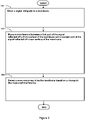
- Figure 2 shows a flowchart of a method according to an exemplifying and non-limiting embodiment for detecting a wave occurring in/on a membrane.
- the method comprises the following actions:
- the signal is directed obliquely to the membrane so that an angle ⁇ between the arrival direction of the signal at the membrane and a geometric perpendicular of the membrane is in the range from 7 degrees to 60 degrees.
- the angle ⁇ is illustrated in figures 1b-1d .
- the above-mentioned angle ⁇ is in the range from 22 degrees to 45 degrees.
- the above-mentioned angle ⁇ is selected so that a distance between a point where the second part of the signal enters the membrane and another point where the second part of the signal exits the membrane is substantially the length of the wave.
- a method according to an exemplifying and non-limiting embodiment comprises estimating variation rate of the measured interference.
- a method comprises estimating travelling speed of the wave based on the variation rate of the measured interference and pre-stored data indicative of the length of the wave.
- a method comprises varying a wavelength of the signal and estimating the thickness of the membrane based on the measured interference corresponding to different wavelengths of the signal.
- the signal is produced with a laser source, e.g. a vertical-cavity surface-emitting laser.
- the interference is measured with an array of sensor elements.
Landscapes
- Health & Medical Sciences (AREA)
- Life Sciences & Earth Sciences (AREA)
- Physics & Mathematics (AREA)
- General Physics & Mathematics (AREA)
- Biomedical Technology (AREA)
- Molecular Biology (AREA)
- Veterinary Medicine (AREA)
- Public Health (AREA)
- General Health & Medical Sciences (AREA)
- Engineering & Computer Science (AREA)
- Ophthalmology & Optometry (AREA)
- Heart & Thoracic Surgery (AREA)
- Medical Informatics (AREA)
- Biophysics (AREA)
- Surgery (AREA)
- Animal Behavior & Ethology (AREA)
- Radiology & Medical Imaging (AREA)
- Pathology (AREA)
- Nuclear Medicine, Radiotherapy & Molecular Imaging (AREA)
- Length Measuring Devices By Optical Means (AREA)
- Investigating Or Analysing Materials By Optical Means (AREA)
- Investigating Or Analyzing Materials By The Use Of Ultrasonic Waves (AREA)
Description
- The disclosure relates to a system for detecting a wave occurring in/on a membrane, for example in/on the cornea of an eye. Furthermore, the disclosure relates to a method for detecting a wave occurring in/on a membrane.
- In many cases, there is a need to detect a wave, such as e.g. a membrane wave or a Lamb wave, occurring in/on a membrane. The wave can be either a standing wave or a travelling wave. In this document the word "membrane" is not limited to substantially 2-dimensional structures whose thickness is extremely small, but the word "membrane" can mean any material layer, a sheet, a plate, or another structure whose thickness is significantly smaller than the other dimensions. Detection of a wave occurring in/on a membrane can be utilized for example in eye pressure measurements where an excitation such as e.g. an air impulse, an ultrasonic tone burst, a shock wave, or some other suitable excitation is used to deform a cornea and thereafter an estimate of the eye pressure is obtained based on a wave caused by the excitation in/on the cornea. A wave occurring in/on a membrane can be detected for example using interferometry where radiation is directed to the membrane under consideration and to a reference reflector. The wave causes changes in the optical length of a propagation path of the radiation reflected off a surface of the membrane. Thus, the wave causes changes in the interference between the radiation reflected off the reference reflector and the radiation reflected off the surface of the membrane. Therefore, the wave can be detected based on the changes of the above-mentioned interference. This detection technique is described e.g. in
US 2018/0193194 A1 . - In many applications, the above-described interferometry-based method for detecting a wave occurring in/on a membrane is however not free from challenges. For example, in conjunction with eye pressure measurements, it can be challenging to keep the reference reflector sufficiently stationary with respect to an eye being measured so that unintentional changes in the position and/or orientation of the reference reflector with respect to the eye do not disturb the eye pressure measurement too much. Thus, there is a need for technical solutions for detecting a wave occurring in/on a membrane so that there is no need for a reference reflector or some other element that must be accurately stationary with respect to the membrane carrying the wave to be detected.
- The following presents a simplified summary to provide basic understanding of some aspects of different invention embodiments. The summary is not an extensive overview of the invention. It is neither intended to identify key or critical elements of the invention nor to delineate the scope of the invention. The following summary merely presents some concepts of the invention in a simplified form as a prelude to a more detailed description of exemplifying and non-limiting embodiments of the invention.
- In this document, the word "geometric" when used as a prefix means a geometric concept that is not necessarily a part of any physical object. The geometric concept can be for example a geometric point, a straight or curved geometric line, a geometric plane, a non-planar geometric surface, a geometric space, or any other geometric entity that is zero, one, two, or three dimensional.
- In accordance with the invention, there is provided a new system for detecting a wave occurring in/on a membrane, e.g. in/on the cornea of an eye. The membrane can be any material layer, a sheet, a plate, or another structure whose thickness is significantly smaller than the other dimensions. A system according to the invention comprises:
- a source for directing a light or ultrasound signal to the membrane, and
- a receiver for measuring interference between a first part of the signal reflected off a front surface of the membrane and a second part of the signal reflected off a rear surface of the membrane, and
- a processing device for detecting the wave based on changes in the measured interference.
- The source and the receiver are positioned obliquely with respect to each other so that the signal is directed obliquely to the membrane when the receiver receives the reflected first and second parts of the signal.
- The detection of the wave occurring on the membrane is based on changes caused by the wave in the length of a V-shaped part of a propagation path of the above-mentioned second part of the signal, wherein the V-shaped part of the propagation path is inside the membrane. The way how the wave changes the length of the above-mentioned V-shaped part is explained later in this document with reference to figures.
- As the detection of the wave is based on the interference between the first part of the signal reflected off the front surface of the membrane and the second part of the signal reflected off the rear surface of the membrane, there is no need for a reference reflector and/or another element that must be accurately stationary with respect to the membrane carrying the wave to be detected.
- In accordance with the invention, there is provided also a new method for detecting a wave occurring in/on a membrane, e.g. in/on the cornea of an eye. A method according to the invention comprises:
- directing a light or ultrasound signal obliquely to the membrane, and
- measuring interference between a first part of the signal reflected off a front surface of the membrane and a second part of the signal reflected off a rear surface of the membrane, and
- detecting the wave based on a change in the measured interference.
- Various exemplifying and non-limiting embodiments are described in accompanied dependent claims.
- Exemplifying and non-limiting embodiments both as to constructions and to methods of operation, together with additional objects and advantages thereof, are best understood from the following description of specific exemplifying embodiments when read in conjunction with the accompanying drawings.
- The verbs "to comprise" and "to include" are used in this document as open limitations that neither exclude nor require the existence of un-recited features. The features recited in dependent claims are mutually freely combinable unless otherwise explicitly stated. Furthermore, it is to be understood that the use of "a" or "an", i.e. a singular form, throughout this document does not exclude a plurality.
- Exemplifying and non-limiting embodiments of the invention and their advantages are explained in greater detail below with reference to the accompanying drawings, in which:
-
figure 1a illustrates a system according to an exemplifying and non-limiting embodiment for detecting a wave occurring in/on a membrane, -
figures 1b-1d illustrate the operational principle of the system illustrated infigure 1a , and -
figure 2 shows a flowchart of a method according to an exemplifying and non-limiting embodiment for detecting a wave occurring in/on a membrane. - The specific examples provided in the description below should not be construed as limiting the scope and/or the applicability of the accompanied claims. Lists and groups of examples provided in the description below are not exhaustive unless otherwise explicitly stated.
-
Figure 1a illustrates a system according to an exemplifying and non-limiting embodiment for detecting a wave occurring in/on amembrane 107. In the exemplifying situation shown infigure 1a , themembrane 107 is the cornea of aneye 106. The wave that travels along themembrane 107 is illustrated infigures 1b, 1c, and 1d which show a section view of themembrane 107 at different moments of time t0, t1, and t2, where t2 > t1 > t0. The system illustrated infigure 1a comprises asource 101 for directing a signal to themembrane 107. Thesource 101 may comprise for example alight source 104 that can be for example a laser source such as e.g. a vertical-cavity surface-emitting laser "VCSEL" for emitting the signal. In this exemplifying case, the signal is a light beam e.g. a laser beam. Thesource 101 may further comprise a lens system for focusing the light beam to themembrane 107. The light beam is advantageously focused on a front surface of themembrane 107 or behind the front surface. The front surface is the surface of themembrane 107 at which the signal arrives first. A diameter of a radiation spot, e.g. a laser spot, on the surface of themembrane 107 can be e.g. in the range from 0.5 mm to 6 mm. It is also possible that the signal is some other propagating wave-front e.g. an ultrasound wave-front. The system comprises areceiver 102 for measuring interference between a first part of the signal reflected off the front surface of themembrane 107 and a second part of the signal reflected off a rear surface of themembrane 107. Infigures 1b-1d , the first part of the signal is depicted with a dashed line arrow and the second part of the signal is depicted with a dash-and-dot line arrow. In exemplifying cases where the signal is electromagnetic radiation e.g. a laser beam, thereceiver 102 may comprise for example a lens system and a multipoint sensor comprising an array ofsensor elements 105. Each sensor element can be for example a photodiode or a photo-transistor. It is also possible that thereceiver 102 comprises a charge-coupled device "CCD". The system further comprises aprocessing device 103 for detecting the wave based on changes in the interference measured by thereceiver 102. In a system according to an exemplifying and non-limiting embodiment, thereceiver 102 comprises a dual photodiode or a photodiode array, where the differential sensing of the adjacent photodiodes is used to improve sensitivity. - The
source 101 and thereceiver 102 are positioned obliquely with respect to each other so that the signal is directed obliquely to themembrane 107 when thereceiver 102 receives the reflected first and second parts of the signal. In a system according to an exemplifying and non-limiting embodiment, thesource 101 and thereceiver 102 are positioned obliquely with respect to each other so that an angle α between a transmission direction of thesource 101 and a reception direction of thereceiver 102 is in the range from 15 degrees to 120 degrees. In a system according to an exemplifying and non-limiting embodiment, the angle α is in the range from 45 degrees to 90 degrees. - The detection of the wave is explained below with reference to
figures 1b-1d . In the situation shown infigure 1b , the wave has not yet arrived at the radiated area of themembrane 107. The interference between the first and second parts of the signal is determined by the wavelength of the signal and the length of a V-shaped part A-B-C of the propagation path of the second part of the signal. In exemplifying cases where the signal is electromagnetic radiation e.g. a laser beam, it is assumed that the term "length" includes the effect of the refraction index of the material of themembrane 107. As shown byfigures 1b-1d , the V-shaped part of the propagation path is inside themembrane 107. In the situation shown infigure 1c , the wave has arrived at the excited area of themembrane 107. As illustrated infigures 1b and 1c , the distance A-B is longer in the situation shown infigure 1c than in the situation shown infigure 1b and the distance B-C is substantially the same in the situations shown infigures 1b and 1c . In the situation shown infigure 1d , the wave has moved further in the direction of propagation than in the situation shown infigure 1c . As illustrated infigures 1d-1d , the distances A-B and B-C are shorter in the situation shown infigure 1d than in the situations shown infigures 1b and 1c . The above-described variation in the length of the V-shaped part A-B-C of the propagation path of the second part of the signal causes changes in the interference between the first and second parts of the signal. As illustrated byfigures 1b-1d , the variation in the length of the V-shaped part A-B-C is strongest when a distance between the point A where the second part of the signal enters themembrane 107 and the point C where the second part of the signal exits themembrane 107 is substantially the length of the wave occurring in/on the membrane. - A system according to an exemplifying and non-limiting embodiment comprises a
support structure 108 arranged to mechanically support thesource 101 and thereceiver 102 so that the above-mentioned angle α shown infigure 1a is changeable. This enables a user of the system to select the angle α so that the distance between the point A where the second part of the signal enters themembrane 107 and the point C where the second part of the signal exits themembrane 107 is substantially the length of the wave occurring in/on the membrane. - In a system according to an exemplifying and non-limiting embodiment, the
processing device 103 is configured to estimate variation rate of the measured interference. The variation rate can be expressed e.g. in Hz. In some exemplifying cases, the variation rate can be for example above 1 kHz. - In a system according to an exemplifying and non-limiting embodiment, the
processing device 103 is configured to estimate travelling speed of the wave based on the variation rate of the measured interference and pre-stored data indicative of the length of the wave. It is also possible that there are two measurement spots simultaneously on the membrane a known distance apart from each other, and the travelling speed is estimated based on the known distance and a time difference between respective changes taking place in the interferences measured for the two measurement spots. - In a system according to an exemplifying and non-limiting embodiment, the
processing device 103 is configured to control thesource 101 to vary the wavelength of the signal and to estimate the thickness of themembrane 107 based on the interference measured with different wavelengths of the signal. The thickness is denoted with T infigures 1b-1d . In this exemplifying case, thesource 101 may comprise for example a vertical-cavity surface-emitting laser "VCSEL" for implementing a wavelength sweep of the signal. The wavelength of the signal emitted by a VCSEL can be changed by changing electric current of the VCSEL. Thus, a VCSEL can be driven with ramped pulses of electric current in direct intensity modulation, and the intrinsic property of the VCSEL produces a wavelength-swept output through the self-heating effect. The signal emitted by a VCSEL has a long coherence length which makes it possible to measure thicknesses of membranes whose thicknesses are few millimeters, whereas a wavelength scan obtained by changing electric current of the VCSEL makes it possible to detect white light interference for coherence widths of few hundreds of micrometers. The system may comprise an airgap for acting as a reference for the thickness determination. Data indicative of the thickness being determined can be obtained with the aid of Fourier transformation of the measured interference signal. As the measurement is carried out not perpendicularly but obliquely, the effect of the obliqueness i.e. a cosine-error is advantageously compensated for in the thickness estimation. For another example, the thickness estimation can be based on for example a pre-stored reference model obtained with experiments carried out with reference membranes having predetermined thicknesses, where the reference model is indicative of the behavior of the interference as a function of the wavelength of the signal and as a function of the thickness of the membrane, i.e. the interference = f(λ, T), λ being the wavelength of the signal and T being the thickness of the membrane. The reference model can be implemented with e.g. a two-dimensional lookup table. The effect of the refraction index of the material of the membrane can be included in the reference model. The thickness of the membrane can be estimated by finding a value for the thickness in the reference model so that the behavior of the interference indicated by the reference model as a function of the wavelength is as close as possible to the behavior of the measured interference as a function of the wavelength. It is also possible that the thickness of the membrane is estimated with a mathematical model based on the theory of wave optics. The mathematical model gives the thickness estimate when parameters indicative of the behavior of the measured interference as a function of the wavelength are given as input data. - The
processing device 103 can be implemented with one or more processor circuits, each of which can be a programmable processor circuit provided with appropriate software, a dedicated hardware processor such as for example an application specific integrated circuit "ASIC", or a configurable hardware processor such as for example a field programmable gate array "FPGA". Furthermore, theprocessing device 103 may comprise one or more memory circuits each of which can be for example a random-access-memory "RAM" circuit. -
Figure 2 shows a flowchart of a method according to an exemplifying and non-limiting embodiment for detecting a wave occurring in/on a membrane. The method comprises the following actions: - action 201: directing a signal obliquely to the membrane, and
- action 202: measuring interference between a first part of the signal reflected off a front surface of the membrane and a second part of the signal reflected off a rear surface of the membrane, and
- action 203: detecting the wave based on a change in the measured interference.
- In a method according to an exemplifying and non-limiting embodiment, the signal is directed obliquely to the membrane so that an angle β between the arrival direction of the signal at the membrane and a geometric perpendicular of the membrane is in the range from 7 degrees to 60 degrees. The angle β is illustrated in
figures 1b-1d . In a method according to an exemplifying and non-limiting embodiment, the above-mentioned angle β is in the range from 22 degrees to 45 degrees. - In a method according to an exemplifying and non-limiting embodiment, the above-mentioned angle β is selected so that a distance between a point where the second part of the signal enters the membrane and another point where the second part of the signal exits the membrane is substantially the length of the wave.
- A method according to an exemplifying and non-limiting embodiment comprises estimating variation rate of the measured interference.
- A method according to an exemplifying and non-limiting embodiment comprises estimating travelling speed of the wave based on the variation rate of the measured interference and pre-stored data indicative of the length of the wave.
- A method according to an exemplifying and non-limiting embodiment comprises varying a wavelength of the signal and estimating the thickness of the membrane based on the measured interference corresponding to different wavelengths of the signal.
- In a method according to an exemplifying and non-limiting embodiment, the signal is produced with a laser source, e.g. a vertical-cavity surface-emitting laser.
- In a method according to an exemplifying and non-limiting embodiment, the interference is measured with an array of sensor elements.
- The non-limiting, specific examples provided in the description given above should not be construed as limiting the scope and/or the applicability of the appended claims. Furthermore, any list or group of examples presented in this document is not exhaustive unless otherwise explicitly stated.
Claims (15)
- A system for detecting a wave occurring in/on a membrane, the system comprising:- a source (101) for directing a light or ultrasound signal to the membrane, and- a receiver (102) for measuring interference between a first part of the signal reflected off a front surface of the membrane and a second part of the signal reflected off a rear surface of the membrane, wherein the source and the receiver are positioned obliquely with respect to each other so that the signal is directed obliquely to the membrane when the receiver receives the reflected first and second parts of the signal, characterized in that the system comprises a processing device (103) for detecting the wave based on a change in the measured interference.
- A system according to claim 1, wherein the source and the receiver are positioned obliquely with respect to each other so that an angle (α) between a transmission direction of the source and a reception direction of the receiver is in a range from 15 degrees to 120 degrees.
- A system according to claim 2, wherein the source and the receiver are positioned obliquely with respect to each other so that the angle (α) is in a range from 45 degrees to 90 degrees.
- A system according to any of claims 1-3, wherein the system comprises a support structure (108) arranged to mechanically support the source (101) and the receiver (102) so that an angle (α) between a transmission direction of the source and a reception direction of the receiver is changeable.
- A system according to any of claims 1-4, wherein the processing device is configured to control the source to vary a wavelength of the signal and to estimate a thickness (T) of the membrane based on the interference measured with different wavelengths of the signal.
- A system according to any of claims 1-5, wherein the source (101) comprises a laser source.
- A system according to claim 6, wherein the laser source is a vertical-cavity surface-emitting laser.
- A system according to any of claims 1-7, wherein the receiver comprises an array of sensor elements (105).
- A method for detecting a wave occurring in/on a membrane (107), the method comprising:- directing (201) a light or ultrasound signal to the membrane, and- measuring (202) interference between a first part of the signal reflected off a front surface of the membrane and a second part of the signal reflected off a rear surface of the membrane, wherein the signal is directed (201) obliquely to the membrane, characterized in that the method comprises detecting (203) the wave based on a change in the measured interference.
- A method according to claim 9, wherein the signal is directed obliquely to the membrane so that an angle (β) between an arrival direction of the signal at the membrane and a geometric perpendicular of the membrane is in a range from 7 degrees to 60 degrees
- A method according to claim 10, wherein the angle (β) is in a range from 22 degrees to 45 degrees.
- A method according to any of claims 9-11, wherein the method comprises selecting an angle (β) between an arrival direction of the signal at the membrane and a geometric perpendicular of the membrane so that a distance between a point (A) where the second part of the signal enters the membrane and another point (C) where the second part of the signal exits the membrane is substantially a length of the wave.
- A method according to any of claims 9-12, wherein the method comprises varying a wavelength of the signal and estimating a thickness of the membrane based on the measured interference corresponding to different wavelengths of the signal.
- A method according to any of claims 9-13, wherein the signal is produced with a laser source.
- A method according to any of claims 9-14, wherein the interference is measured with an array of sensor elements.
Applications Claiming Priority (2)
| Application Number | Priority Date | Filing Date | Title |
|---|---|---|---|
| FI20195098A FI20195098A1 (en) | 2019-02-12 | 2019-02-12 | System and method for detecting a wave occurring in/on a membrane |
| PCT/FI2020/050069 WO2020165495A1 (en) | 2019-02-12 | 2020-02-05 | System and method for detecting a wave occurring in/on a membrane |
Publications (2)
| Publication Number | Publication Date |
|---|---|
| EP3924690A1 EP3924690A1 (en) | 2021-12-22 |
| EP3924690B1 true EP3924690B1 (en) | 2022-12-21 |
Family
ID=69740380
Family Applications (1)
| Application Number | Title | Priority Date | Filing Date |
|---|---|---|---|
| EP20708531.7A Active EP3924690B1 (en) | 2019-02-12 | 2020-02-05 | System and method for detecting a wave occurring in/on a membrane |
Country Status (6)
| Country | Link |
|---|---|
| US (1) | US12031809B2 (en) |
| EP (1) | EP3924690B1 (en) |
| CN (1) | CN113424015B (en) |
| ES (1) | ES2936798T3 (en) |
| FI (1) | FI20195098A1 (en) |
| WO (1) | WO2020165495A1 (en) |
Family Cites Families (12)
| Publication number | Priority date | Publication date | Assignee | Title |
|---|---|---|---|---|
| EP1446634A4 (en) * | 2001-10-26 | 2010-04-07 | Univ Rochester | BIOMOLECULAR DETECTION METHOD AND SYSTEM THEREFOR |
| US20040193033A1 (en) * | 2002-10-04 | 2004-09-30 | Badehi Avner Pierre | Noninvasive methods and apparatuses for measuring the intraocular pressure of a mammal eye |
| US7477571B2 (en) | 2003-04-03 | 2009-01-13 | Sri International | Method for detecting vibrations in a biological organism using real-time vibration imaging |
| US20050030473A1 (en) * | 2003-06-12 | 2005-02-10 | Welch Allyn, Inc. | Apparatus and method for determining intraocular pressure and corneal thickness |
| DE102008008732A1 (en) * | 2008-02-11 | 2009-08-13 | Carl Zeiss Meditec Ag | Method and device for determining corneal radii |
| FI20135401L (en) * | 2013-04-19 | 2014-10-20 | Garuda Oy | Measurement method and measurement arrangement for utilizing electromagnetic waves |
| FI20145205A7 (en) * | 2014-03-04 | 2015-09-05 | Photono Oy | Method and arrangement for eye pressure measurements |
| CN107072529B (en) * | 2014-07-17 | 2022-01-18 | 爱音医疗股份有限公司 | Measuring ocular parameters using vibrations induced in the eye |
| WO2017037330A1 (en) * | 2015-09-03 | 2017-03-09 | Photono Oy | Method and arrangement for eye measurements |
| CN107664476B (en) * | 2016-07-28 | 2020-06-05 | 中微半导体设备(上海)股份有限公司 | Optical detection device and detection method for semiconductor equipment |
| JP6550101B2 (en) * | 2017-07-13 | 2019-07-24 | Jfeテクノリサーチ株式会社 | Film thickness measuring method and film thickness measuring apparatus |
| CN107607051B (en) * | 2017-10-26 | 2019-07-30 | 京东方科技集团股份有限公司 | A film thickness detection device |
-
2019
- 2019-02-12 FI FI20195098A patent/FI20195098A1/en not_active Application Discontinuation
-
2020
- 2020-02-05 WO PCT/FI2020/050069 patent/WO2020165495A1/en not_active Ceased
- 2020-02-05 ES ES20708531T patent/ES2936798T3/en active Active
- 2020-02-05 CN CN202080013516.3A patent/CN113424015B/en active Active
- 2020-02-05 EP EP20708531.7A patent/EP3924690B1/en active Active
- 2020-02-25 US US17/430,046 patent/US12031809B2/en active Active
Also Published As
| Publication number | Publication date |
|---|---|
| WO2020165495A1 (en) | 2020-08-20 |
| CN113424015B (en) | 2023-06-20 |
| CN113424015A (en) | 2021-09-21 |
| ES2936798T3 (en) | 2023-03-22 |
| EP3924690A1 (en) | 2021-12-22 |
| FI20195098A1 (en) | 2020-08-13 |
| US12031809B2 (en) | 2024-07-09 |
| US20220113125A1 (en) | 2022-04-14 |
Similar Documents
| Publication | Publication Date | Title |
|---|---|---|
| RU2442107C2 (en) | Device for optical distance measurement | |
| KR102324620B1 (en) | Lidar system with non-uniform sensitivity response | |
| US20170199272A1 (en) | Optical reflection sensor and electronic device | |
| US9958546B2 (en) | Laser rangefinder and method of measuring distance and direction | |
| JP2018200927A (en) | Electromagnetic wave detection device and information acquisition system | |
| KR101912972B1 (en) | Ultrasonic inspection apparatus and ultrasonic inspection method | |
| KR20130064684A (en) | Terahertz continuous wave system and three dimension imaging abtainning method thereof | |
| EP3199946B1 (en) | Deformation detecting device | |
| EP2598909B1 (en) | Apparatus for measuring a distance | |
| EP3271749B1 (en) | Multiple-beam triangulation-based range finder and method | |
| US12031809B2 (en) | System and method for detecting a wave occurring in/on a membrane | |
| CN113063736B (en) | Femtosecond laser-based ultrasonic measurement apparatus for 3D printing process and 3D printing system having the same | |
| WO2006109298A3 (en) | An optical screen, systems and methods for producing and operating same | |
| KR20120069487A (en) | Active optical radar apparatus | |
| US9182281B1 (en) | Robust terahertz spectrometer configuration against scanner heads misalignment | |
| JP5098246B2 (en) | Object identification method and object identification apparatus | |
| WO2019044823A1 (en) | Optical device | |
| EP1016849A4 (en) | LENGTH MEASURING INSTRUMENT | |
| JP7687431B2 (en) | Distance measuring device and distance measuring method | |
| CN111750982A (en) | Laser Monitoring Module and Laser Monitoring System | |
| KR100733539B1 (en) | Ultrasonic Measurement Apparatus and Method of High Temperature Measurement Object Using Laser | |
| CN115280164B (en) | Equipment for determining the speed and/or length of a product | |
| RU2473046C1 (en) | Laser range finder (versions) | |
| KR102018961B1 (en) | TOF measurement system using selective aperture for improving thickness detect capability of scattering medium | |
| JP2008286595A (en) | Laser range finder |
Legal Events
| Date | Code | Title | Description |
|---|---|---|---|
| STAA | Information on the status of an ep patent application or granted ep patent |
Free format text: STATUS: UNKNOWN |
|
| STAA | Information on the status of an ep patent application or granted ep patent |
Free format text: STATUS: THE INTERNATIONAL PUBLICATION HAS BEEN MADE |
|
| PUAI | Public reference made under article 153(3) epc to a published international application that has entered the european phase |
Free format text: ORIGINAL CODE: 0009012 |
|
| STAA | Information on the status of an ep patent application or granted ep patent |
Free format text: STATUS: REQUEST FOR EXAMINATION WAS MADE |
|
| 17P | Request for examination filed |
Effective date: 20210715 |
|
| AK | Designated contracting states |
Kind code of ref document: A1 Designated state(s): AL AT BE BG CH CY CZ DE DK EE ES FI FR GB GR HR HU IE IS IT LI LT LU LV MC MK MT NL NO PL PT RO RS SE SI SK SM TR |
|
| DAV | Request for validation of the european patent (deleted) | ||
| DAX | Request for extension of the european patent (deleted) | ||
| GRAP | Despatch of communication of intention to grant a patent |
Free format text: ORIGINAL CODE: EPIDOSNIGR1 |
|
| STAA | Information on the status of an ep patent application or granted ep patent |
Free format text: STATUS: GRANT OF PATENT IS INTENDED |
|
| RIC1 | Information provided on ipc code assigned before grant |
Ipc: A61B 3/10 20060101ALI20220905BHEP Ipc: G01B 17/02 20060101ALI20220905BHEP Ipc: G01B 11/06 20060101AFI20220905BHEP |
|
| INTG | Intention to grant announced |
Effective date: 20220930 |
|
| GRAS | Grant fee paid |
Free format text: ORIGINAL CODE: EPIDOSNIGR3 |
|
| GRAA | (expected) grant |
Free format text: ORIGINAL CODE: 0009210 |
|
| STAA | Information on the status of an ep patent application or granted ep patent |
Free format text: STATUS: THE PATENT HAS BEEN GRANTED |
|
| AK | Designated contracting states |
Kind code of ref document: B1 Designated state(s): AL AT BE BG CH CY CZ DE DK EE ES FI FR GB GR HR HU IE IS IT LI LT LU LV MC MK MT NL NO PL PT RO RS SE SI SK SM TR |
|
| REG | Reference to a national code |
Ref country code: GB Ref legal event code: FG4D |
|
| REG | Reference to a national code |
Ref country code: CH Ref legal event code: EP |
|
| REG | Reference to a national code |
Ref country code: DE Ref legal event code: R096 Ref document number: 602020007084 Country of ref document: DE |
|
| REG | Reference to a national code |
Ref country code: AT Ref legal event code: REF Ref document number: 1539293 Country of ref document: AT Kind code of ref document: T Effective date: 20230115 |
|
| REG | Reference to a national code |
Ref country code: IE Ref legal event code: FG4D |
|
| REG | Reference to a national code |
Ref country code: ES Ref legal event code: FG2A Ref document number: 2936798 Country of ref document: ES Kind code of ref document: T3 Effective date: 20230322 |
|
| REG | Reference to a national code |
Ref country code: LT Ref legal event code: MG9D |
|
| REG | Reference to a national code |
Ref country code: NL Ref legal event code: MP Effective date: 20221221 |
|
| PG25 | Lapsed in a contracting state [announced via postgrant information from national office to epo] |
Ref country code: SE Free format text: LAPSE BECAUSE OF FAILURE TO SUBMIT A TRANSLATION OF THE DESCRIPTION OR TO PAY THE FEE WITHIN THE PRESCRIBED TIME-LIMIT Effective date: 20221221 Ref country code: NO Free format text: LAPSE BECAUSE OF FAILURE TO SUBMIT A TRANSLATION OF THE DESCRIPTION OR TO PAY THE FEE WITHIN THE PRESCRIBED TIME-LIMIT Effective date: 20230321 Ref country code: LT Free format text: LAPSE BECAUSE OF FAILURE TO SUBMIT A TRANSLATION OF THE DESCRIPTION OR TO PAY THE FEE WITHIN THE PRESCRIBED TIME-LIMIT Effective date: 20221221 Ref country code: FI Free format text: LAPSE BECAUSE OF FAILURE TO SUBMIT A TRANSLATION OF THE DESCRIPTION OR TO PAY THE FEE WITHIN THE PRESCRIBED TIME-LIMIT Effective date: 20221221 |
|
| REG | Reference to a national code |
Ref country code: AT Ref legal event code: MK05 Ref document number: 1539293 Country of ref document: AT Kind code of ref document: T Effective date: 20221221 |
|
| PG25 | Lapsed in a contracting state [announced via postgrant information from national office to epo] |
Ref country code: RS Free format text: LAPSE BECAUSE OF FAILURE TO SUBMIT A TRANSLATION OF THE DESCRIPTION OR TO PAY THE FEE WITHIN THE PRESCRIBED TIME-LIMIT Effective date: 20221221 Ref country code: LV Free format text: LAPSE BECAUSE OF FAILURE TO SUBMIT A TRANSLATION OF THE DESCRIPTION OR TO PAY THE FEE WITHIN THE PRESCRIBED TIME-LIMIT Effective date: 20221221 Ref country code: HR Free format text: LAPSE BECAUSE OF FAILURE TO SUBMIT A TRANSLATION OF THE DESCRIPTION OR TO PAY THE FEE WITHIN THE PRESCRIBED TIME-LIMIT Effective date: 20221221 Ref country code: GR Free format text: LAPSE BECAUSE OF FAILURE TO SUBMIT A TRANSLATION OF THE DESCRIPTION OR TO PAY THE FEE WITHIN THE PRESCRIBED TIME-LIMIT Effective date: 20230322 |
|
| PG25 | Lapsed in a contracting state [announced via postgrant information from national office to epo] |
Ref country code: NL Free format text: LAPSE BECAUSE OF FAILURE TO SUBMIT A TRANSLATION OF THE DESCRIPTION OR TO PAY THE FEE WITHIN THE PRESCRIBED TIME-LIMIT Effective date: 20221221 |
|
| PG25 | Lapsed in a contracting state [announced via postgrant information from national office to epo] |
Ref country code: SM Free format text: LAPSE BECAUSE OF FAILURE TO SUBMIT A TRANSLATION OF THE DESCRIPTION OR TO PAY THE FEE WITHIN THE PRESCRIBED TIME-LIMIT Effective date: 20221221 Ref country code: RO Free format text: LAPSE BECAUSE OF FAILURE TO SUBMIT A TRANSLATION OF THE DESCRIPTION OR TO PAY THE FEE WITHIN THE PRESCRIBED TIME-LIMIT Effective date: 20221221 Ref country code: PT Free format text: LAPSE BECAUSE OF FAILURE TO SUBMIT A TRANSLATION OF THE DESCRIPTION OR TO PAY THE FEE WITHIN THE PRESCRIBED TIME-LIMIT Effective date: 20230421 Ref country code: EE Free format text: LAPSE BECAUSE OF FAILURE TO SUBMIT A TRANSLATION OF THE DESCRIPTION OR TO PAY THE FEE WITHIN THE PRESCRIBED TIME-LIMIT Effective date: 20221221 Ref country code: CZ Free format text: LAPSE BECAUSE OF FAILURE TO SUBMIT A TRANSLATION OF THE DESCRIPTION OR TO PAY THE FEE WITHIN THE PRESCRIBED TIME-LIMIT Effective date: 20221221 Ref country code: AT Free format text: LAPSE BECAUSE OF FAILURE TO SUBMIT A TRANSLATION OF THE DESCRIPTION OR TO PAY THE FEE WITHIN THE PRESCRIBED TIME-LIMIT Effective date: 20221221 |
|
| PG25 | Lapsed in a contracting state [announced via postgrant information from national office to epo] |
Ref country code: SK Free format text: LAPSE BECAUSE OF FAILURE TO SUBMIT A TRANSLATION OF THE DESCRIPTION OR TO PAY THE FEE WITHIN THE PRESCRIBED TIME-LIMIT Effective date: 20221221 Ref country code: PL Free format text: LAPSE BECAUSE OF FAILURE TO SUBMIT A TRANSLATION OF THE DESCRIPTION OR TO PAY THE FEE WITHIN THE PRESCRIBED TIME-LIMIT Effective date: 20221221 Ref country code: IS Free format text: LAPSE BECAUSE OF FAILURE TO SUBMIT A TRANSLATION OF THE DESCRIPTION OR TO PAY THE FEE WITHIN THE PRESCRIBED TIME-LIMIT Effective date: 20230421 Ref country code: AL Free format text: LAPSE BECAUSE OF FAILURE TO SUBMIT A TRANSLATION OF THE DESCRIPTION OR TO PAY THE FEE WITHIN THE PRESCRIBED TIME-LIMIT Effective date: 20221221 |
|
| REG | Reference to a national code |
Ref country code: DE Ref legal event code: R097 Ref document number: 602020007084 Country of ref document: DE |
|
| PG25 | Lapsed in a contracting state [announced via postgrant information from national office to epo] |
Ref country code: MC Free format text: LAPSE BECAUSE OF FAILURE TO SUBMIT A TRANSLATION OF THE DESCRIPTION OR TO PAY THE FEE WITHIN THE PRESCRIBED TIME-LIMIT Effective date: 20221221 |
|
| REG | Reference to a national code |
Ref country code: CH Ref legal event code: PL |
|
| REG | Reference to a national code |
Ref country code: BE Ref legal event code: MM Effective date: 20230228 |
|
| PLBE | No opposition filed within time limit |
Free format text: ORIGINAL CODE: 0009261 |
|
| STAA | Information on the status of an ep patent application or granted ep patent |
Free format text: STATUS: NO OPPOSITION FILED WITHIN TIME LIMIT |
|
| PG25 | Lapsed in a contracting state [announced via postgrant information from national office to epo] |
Ref country code: LU Free format text: LAPSE BECAUSE OF NON-PAYMENT OF DUE FEES Effective date: 20230205 Ref country code: LI Free format text: LAPSE BECAUSE OF NON-PAYMENT OF DUE FEES Effective date: 20230228 Ref country code: DK Free format text: LAPSE BECAUSE OF FAILURE TO SUBMIT A TRANSLATION OF THE DESCRIPTION OR TO PAY THE FEE WITHIN THE PRESCRIBED TIME-LIMIT Effective date: 20221221 Ref country code: CH Free format text: LAPSE BECAUSE OF NON-PAYMENT OF DUE FEES Effective date: 20230228 |
|
| 26N | No opposition filed |
Effective date: 20230922 |
|
| REG | Reference to a national code |
Ref country code: IE Ref legal event code: MM4A |
|
| PG25 | Lapsed in a contracting state [announced via postgrant information from national office to epo] |
Ref country code: SI Free format text: LAPSE BECAUSE OF FAILURE TO SUBMIT A TRANSLATION OF THE DESCRIPTION OR TO PAY THE FEE WITHIN THE PRESCRIBED TIME-LIMIT Effective date: 20221221 Ref country code: IE Free format text: LAPSE BECAUSE OF NON-PAYMENT OF DUE FEES Effective date: 20230205 |
|
| PG25 | Lapsed in a contracting state [announced via postgrant information from national office to epo] |
Ref country code: BE Free format text: LAPSE BECAUSE OF NON-PAYMENT OF DUE FEES Effective date: 20230228 |
|
| PG25 | Lapsed in a contracting state [announced via postgrant information from national office to epo] |
Ref country code: BG Free format text: LAPSE BECAUSE OF FAILURE TO SUBMIT A TRANSLATION OF THE DESCRIPTION OR TO PAY THE FEE WITHIN THE PRESCRIBED TIME-LIMIT Effective date: 20221221 |
|
| PG25 | Lapsed in a contracting state [announced via postgrant information from national office to epo] |
Ref country code: BG Free format text: LAPSE BECAUSE OF FAILURE TO SUBMIT A TRANSLATION OF THE DESCRIPTION OR TO PAY THE FEE WITHIN THE PRESCRIBED TIME-LIMIT Effective date: 20221221 |
|
| PGFP | Annual fee paid to national office [announced via postgrant information from national office to epo] |
Ref country code: ES Payment date: 20250331 Year of fee payment: 6 |
|
| PG25 | Lapsed in a contracting state [announced via postgrant information from national office to epo] |
Ref country code: CY Free format text: LAPSE BECAUSE OF FAILURE TO SUBMIT A TRANSLATION OF THE DESCRIPTION OR TO PAY THE FEE WITHIN THE PRESCRIBED TIME-LIMIT; INVALID AB INITIO Effective date: 20200205 |
|
| PG25 | Lapsed in a contracting state [announced via postgrant information from national office to epo] |
Ref country code: HU Free format text: LAPSE BECAUSE OF FAILURE TO SUBMIT A TRANSLATION OF THE DESCRIPTION OR TO PAY THE FEE WITHIN THE PRESCRIBED TIME-LIMIT; INVALID AB INITIO Effective date: 20200205 |
|
| PG25 | Lapsed in a contracting state [announced via postgrant information from national office to epo] |
Ref country code: TR Free format text: LAPSE BECAUSE OF FAILURE TO SUBMIT A TRANSLATION OF THE DESCRIPTION OR TO PAY THE FEE WITHIN THE PRESCRIBED TIME-LIMIT Effective date: 20221221 |
|
| PGFP | Annual fee paid to national office [announced via postgrant information from national office to epo] |
Ref country code: GB Payment date: 20260220 Year of fee payment: 7 |
|
| PGFP | Annual fee paid to national office [announced via postgrant information from national office to epo] |
Ref country code: DE Payment date: 20260218 Year of fee payment: 7 |
|
| PGFP | Annual fee paid to national office [announced via postgrant information from national office to epo] |
Ref country code: IT Payment date: 20260219 Year of fee payment: 7 |
|
| PGFP | Annual fee paid to national office [announced via postgrant information from national office to epo] |
Ref country code: FR Payment date: 20260219 Year of fee payment: 7 |