EP3924210B1 - Desired departure temperature for a battery in a vehicle - Google Patents
Desired departure temperature for a battery in a vehicle Download PDFInfo
- Publication number
- EP3924210B1 EP3924210B1 EP19915157.2A EP19915157A EP3924210B1 EP 3924210 B1 EP3924210 B1 EP 3924210B1 EP 19915157 A EP19915157 A EP 19915157A EP 3924210 B1 EP3924210 B1 EP 3924210B1
- Authority
- EP
- European Patent Office
- Prior art keywords
- battery
- temperature
- trip
- departure
- ddt
- Prior art date
- Legal status (The legal status is an assumption and is not a legal conclusion. Google has not performed a legal analysis and makes no representation as to the accuracy of the status listed.)
- Active
Links
Images


Classifications
-
- B—PERFORMING OPERATIONS; TRANSPORTING
- B60—VEHICLES IN GENERAL
- B60L—PROPULSION OF ELECTRICALLY-PROPELLED VEHICLES; SUPPLYING ELECTRIC POWER FOR AUXILIARY EQUIPMENT OF ELECTRICALLY-PROPELLED VEHICLES; ELECTRODYNAMIC BRAKE SYSTEMS FOR VEHICLES IN GENERAL; MAGNETIC SUSPENSION OR LEVITATION FOR VEHICLES; MONITORING OPERATING VARIABLES OF ELECTRICALLY-PROPELLED VEHICLES; ELECTRIC SAFETY DEVICES FOR ELECTRICALLY-PROPELLED VEHICLES
- B60L58/00—Methods or circuit arrangements for monitoring or controlling batteries or fuel cells, specially adapted for electric vehicles
- B60L58/10—Methods or circuit arrangements for monitoring or controlling batteries or fuel cells, specially adapted for electric vehicles for monitoring or controlling batteries
- B60L58/24—Methods or circuit arrangements for monitoring or controlling batteries or fuel cells, specially adapted for electric vehicles for monitoring or controlling batteries for controlling the temperature of batteries
- B60L58/26—Methods or circuit arrangements for monitoring or controlling batteries or fuel cells, specially adapted for electric vehicles for monitoring or controlling batteries for controlling the temperature of batteries by cooling
-
- B—PERFORMING OPERATIONS; TRANSPORTING
- B60—VEHICLES IN GENERAL
- B60L—PROPULSION OF ELECTRICALLY-PROPELLED VEHICLES; SUPPLYING ELECTRIC POWER FOR AUXILIARY EQUIPMENT OF ELECTRICALLY-PROPELLED VEHICLES; ELECTRODYNAMIC BRAKE SYSTEMS FOR VEHICLES IN GENERAL; MAGNETIC SUSPENSION OR LEVITATION FOR VEHICLES; MONITORING OPERATING VARIABLES OF ELECTRICALLY-PROPELLED VEHICLES; ELECTRIC SAFETY DEVICES FOR ELECTRICALLY-PROPELLED VEHICLES
- B60L58/00—Methods or circuit arrangements for monitoring or controlling batteries or fuel cells, specially adapted for electric vehicles
- B60L58/10—Methods or circuit arrangements for monitoring or controlling batteries or fuel cells, specially adapted for electric vehicles for monitoring or controlling batteries
- B60L58/24—Methods or circuit arrangements for monitoring or controlling batteries or fuel cells, specially adapted for electric vehicles for monitoring or controlling batteries for controlling the temperature of batteries
-
- B—PERFORMING OPERATIONS; TRANSPORTING
- B60—VEHICLES IN GENERAL
- B60L—PROPULSION OF ELECTRICALLY-PROPELLED VEHICLES; SUPPLYING ELECTRIC POWER FOR AUXILIARY EQUIPMENT OF ELECTRICALLY-PROPELLED VEHICLES; ELECTRODYNAMIC BRAKE SYSTEMS FOR VEHICLES IN GENERAL; MAGNETIC SUSPENSION OR LEVITATION FOR VEHICLES; MONITORING OPERATING VARIABLES OF ELECTRICALLY-PROPELLED VEHICLES; ELECTRIC SAFETY DEVICES FOR ELECTRICALLY-PROPELLED VEHICLES
- B60L53/00—Methods of charging batteries, specially adapted for electric vehicles; Charging stations or on-board charging equipment therefor; Exchange of energy storage elements in electric vehicles
- B60L53/60—Monitoring or controlling charging stations
- B60L53/64—Optimising energy costs, e.g. responding to electricity rates
-
- B—PERFORMING OPERATIONS; TRANSPORTING
- B60—VEHICLES IN GENERAL
- B60L—PROPULSION OF ELECTRICALLY-PROPELLED VEHICLES; SUPPLYING ELECTRIC POWER FOR AUXILIARY EQUIPMENT OF ELECTRICALLY-PROPELLED VEHICLES; ELECTRODYNAMIC BRAKE SYSTEMS FOR VEHICLES IN GENERAL; MAGNETIC SUSPENSION OR LEVITATION FOR VEHICLES; MONITORING OPERATING VARIABLES OF ELECTRICALLY-PROPELLED VEHICLES; ELECTRIC SAFETY DEVICES FOR ELECTRICALLY-PROPELLED VEHICLES
- B60L53/00—Methods of charging batteries, specially adapted for electric vehicles; Charging stations or on-board charging equipment therefor; Exchange of energy storage elements in electric vehicles
- B60L53/60—Monitoring or controlling charging stations
- B60L53/66—Data transfer between charging stations and vehicles
- B60L53/665—Methods related to measuring, billing or payment
-
- B—PERFORMING OPERATIONS; TRANSPORTING
- B60—VEHICLES IN GENERAL
- B60L—PROPULSION OF ELECTRICALLY-PROPELLED VEHICLES; SUPPLYING ELECTRIC POWER FOR AUXILIARY EQUIPMENT OF ELECTRICALLY-PROPELLED VEHICLES; ELECTRODYNAMIC BRAKE SYSTEMS FOR VEHICLES IN GENERAL; MAGNETIC SUSPENSION OR LEVITATION FOR VEHICLES; MONITORING OPERATING VARIABLES OF ELECTRICALLY-PROPELLED VEHICLES; ELECTRIC SAFETY DEVICES FOR ELECTRICALLY-PROPELLED VEHICLES
- B60L58/00—Methods or circuit arrangements for monitoring or controlling batteries or fuel cells, specially adapted for electric vehicles
- B60L58/10—Methods or circuit arrangements for monitoring or controlling batteries or fuel cells, specially adapted for electric vehicles for monitoring or controlling batteries
- B60L58/16—Methods or circuit arrangements for monitoring or controlling batteries or fuel cells, specially adapted for electric vehicles for monitoring or controlling batteries responding to battery ageing, e.g. to the number of charging cycles or the state of health [SoH]
-
- B—PERFORMING OPERATIONS; TRANSPORTING
- B60—VEHICLES IN GENERAL
- B60L—PROPULSION OF ELECTRICALLY-PROPELLED VEHICLES; SUPPLYING ELECTRIC POWER FOR AUXILIARY EQUIPMENT OF ELECTRICALLY-PROPELLED VEHICLES; ELECTRODYNAMIC BRAKE SYSTEMS FOR VEHICLES IN GENERAL; MAGNETIC SUSPENSION OR LEVITATION FOR VEHICLES; MONITORING OPERATING VARIABLES OF ELECTRICALLY-PROPELLED VEHICLES; ELECTRIC SAFETY DEVICES FOR ELECTRICALLY-PROPELLED VEHICLES
- B60L58/00—Methods or circuit arrangements for monitoring or controlling batteries or fuel cells, specially adapted for electric vehicles
- B60L58/10—Methods or circuit arrangements for monitoring or controlling batteries or fuel cells, specially adapted for electric vehicles for monitoring or controlling batteries
- B60L58/24—Methods or circuit arrangements for monitoring or controlling batteries or fuel cells, specially adapted for electric vehicles for monitoring or controlling batteries for controlling the temperature of batteries
- B60L58/27—Methods or circuit arrangements for monitoring or controlling batteries or fuel cells, specially adapted for electric vehicles for monitoring or controlling batteries for controlling the temperature of batteries by heating
-
- H—ELECTRICITY
- H01—ELECTRIC ELEMENTS
- H01M—PROCESSES OR MEANS, e.g. BATTERIES, FOR THE DIRECT CONVERSION OF CHEMICAL ENERGY INTO ELECTRICAL ENERGY
- H01M10/00—Secondary cells; Manufacture thereof
- H01M10/60—Heating or cooling; Temperature control
- H01M10/61—Types of temperature control
- H01M10/617—Types of temperature control for achieving uniformity or desired distribution of temperature
-
- H—ELECTRICITY
- H01—ELECTRIC ELEMENTS
- H01M—PROCESSES OR MEANS, e.g. BATTERIES, FOR THE DIRECT CONVERSION OF CHEMICAL ENERGY INTO ELECTRICAL ENERGY
- H01M10/00—Secondary cells; Manufacture thereof
- H01M10/60—Heating or cooling; Temperature control
- H01M10/62—Heating or cooling; Temperature control specially adapted for specific applications
- H01M10/625—Vehicles
-
- H—ELECTRICITY
- H01—ELECTRIC ELEMENTS
- H01M—PROCESSES OR MEANS, e.g. BATTERIES, FOR THE DIRECT CONVERSION OF CHEMICAL ENERGY INTO ELECTRICAL ENERGY
- H01M10/00—Secondary cells; Manufacture thereof
- H01M10/60—Heating or cooling; Temperature control
- H01M10/63—Control systems
- H01M10/633—Control systems characterised by algorithms, flow charts, software details or the like
-
- H—ELECTRICITY
- H01—ELECTRIC ELEMENTS
- H01M—PROCESSES OR MEANS, e.g. BATTERIES, FOR THE DIRECT CONVERSION OF CHEMICAL ENERGY INTO ELECTRICAL ENERGY
- H01M10/00—Secondary cells; Manufacture thereof
- H01M10/60—Heating or cooling; Temperature control
- H01M10/63—Control systems
- H01M10/635—Control systems based on ambient temperature
-
- B—PERFORMING OPERATIONS; TRANSPORTING
- B60—VEHICLES IN GENERAL
- B60L—PROPULSION OF ELECTRICALLY-PROPELLED VEHICLES; SUPPLYING ELECTRIC POWER FOR AUXILIARY EQUIPMENT OF ELECTRICALLY-PROPELLED VEHICLES; ELECTRODYNAMIC BRAKE SYSTEMS FOR VEHICLES IN GENERAL; MAGNETIC SUSPENSION OR LEVITATION FOR VEHICLES; MONITORING OPERATING VARIABLES OF ELECTRICALLY-PROPELLED VEHICLES; ELECTRIC SAFETY DEVICES FOR ELECTRICALLY-PROPELLED VEHICLES
- B60L2200/00—Type of vehicles
- B60L2200/10—Air crafts
-
- B—PERFORMING OPERATIONS; TRANSPORTING
- B60—VEHICLES IN GENERAL
- B60L—PROPULSION OF ELECTRICALLY-PROPELLED VEHICLES; SUPPLYING ELECTRIC POWER FOR AUXILIARY EQUIPMENT OF ELECTRICALLY-PROPELLED VEHICLES; ELECTRODYNAMIC BRAKE SYSTEMS FOR VEHICLES IN GENERAL; MAGNETIC SUSPENSION OR LEVITATION FOR VEHICLES; MONITORING OPERATING VARIABLES OF ELECTRICALLY-PROPELLED VEHICLES; ELECTRIC SAFETY DEVICES FOR ELECTRICALLY-PROPELLED VEHICLES
- B60L2200/00—Type of vehicles
- B60L2200/22—Microcars, e.g. golf cars
-
- B—PERFORMING OPERATIONS; TRANSPORTING
- B60—VEHICLES IN GENERAL
- B60L—PROPULSION OF ELECTRICALLY-PROPELLED VEHICLES; SUPPLYING ELECTRIC POWER FOR AUXILIARY EQUIPMENT OF ELECTRICALLY-PROPELLED VEHICLES; ELECTRODYNAMIC BRAKE SYSTEMS FOR VEHICLES IN GENERAL; MAGNETIC SUSPENSION OR LEVITATION FOR VEHICLES; MONITORING OPERATING VARIABLES OF ELECTRICALLY-PROPELLED VEHICLES; ELECTRIC SAFETY DEVICES FOR ELECTRICALLY-PROPELLED VEHICLES
- B60L2240/00—Control parameters of input or output; Target parameters
- B60L2240/40—Drive Train control parameters
- B60L2240/54—Drive Train control parameters related to batteries
- B60L2240/545—Temperature
-
- B—PERFORMING OPERATIONS; TRANSPORTING
- B60—VEHICLES IN GENERAL
- B60L—PROPULSION OF ELECTRICALLY-PROPELLED VEHICLES; SUPPLYING ELECTRIC POWER FOR AUXILIARY EQUIPMENT OF ELECTRICALLY-PROPELLED VEHICLES; ELECTRODYNAMIC BRAKE SYSTEMS FOR VEHICLES IN GENERAL; MAGNETIC SUSPENSION OR LEVITATION FOR VEHICLES; MONITORING OPERATING VARIABLES OF ELECTRICALLY-PROPELLED VEHICLES; ELECTRIC SAFETY DEVICES FOR ELECTRICALLY-PROPELLED VEHICLES
- B60L2240/00—Control parameters of input or output; Target parameters
- B60L2240/60—Navigation input
- B60L2240/66—Ambient conditions
- B60L2240/662—Temperature
-
- B—PERFORMING OPERATIONS; TRANSPORTING
- B60—VEHICLES IN GENERAL
- B60L—PROPULSION OF ELECTRICALLY-PROPELLED VEHICLES; SUPPLYING ELECTRIC POWER FOR AUXILIARY EQUIPMENT OF ELECTRICALLY-PROPELLED VEHICLES; ELECTRODYNAMIC BRAKE SYSTEMS FOR VEHICLES IN GENERAL; MAGNETIC SUSPENSION OR LEVITATION FOR VEHICLES; MONITORING OPERATING VARIABLES OF ELECTRICALLY-PROPELLED VEHICLES; ELECTRIC SAFETY DEVICES FOR ELECTRICALLY-PROPELLED VEHICLES
- B60L2250/00—Driver interactions
- B60L2250/14—Driver interactions by input of vehicle departure time
-
- B—PERFORMING OPERATIONS; TRANSPORTING
- B60—VEHICLES IN GENERAL
- B60L—PROPULSION OF ELECTRICALLY-PROPELLED VEHICLES; SUPPLYING ELECTRIC POWER FOR AUXILIARY EQUIPMENT OF ELECTRICALLY-PROPELLED VEHICLES; ELECTRODYNAMIC BRAKE SYSTEMS FOR VEHICLES IN GENERAL; MAGNETIC SUSPENSION OR LEVITATION FOR VEHICLES; MONITORING OPERATING VARIABLES OF ELECTRICALLY-PROPELLED VEHICLES; ELECTRIC SAFETY DEVICES FOR ELECTRICALLY-PROPELLED VEHICLES
- B60L2260/00—Operating Modes
- B60L2260/40—Control modes
- B60L2260/50—Control modes by future state prediction
- B60L2260/56—Temperature prediction, e.g. for pre-cooling
-
- B—PERFORMING OPERATIONS; TRANSPORTING
- B60—VEHICLES IN GENERAL
- B60L—PROPULSION OF ELECTRICALLY-PROPELLED VEHICLES; SUPPLYING ELECTRIC POWER FOR AUXILIARY EQUIPMENT OF ELECTRICALLY-PROPELLED VEHICLES; ELECTRODYNAMIC BRAKE SYSTEMS FOR VEHICLES IN GENERAL; MAGNETIC SUSPENSION OR LEVITATION FOR VEHICLES; MONITORING OPERATING VARIABLES OF ELECTRICALLY-PROPELLED VEHICLES; ELECTRIC SAFETY DEVICES FOR ELECTRICALLY-PROPELLED VEHICLES
- B60L2260/00—Operating Modes
- B60L2260/40—Control modes
- B60L2260/50—Control modes by future state prediction
- B60L2260/58—Departure time prediction
-
- B—PERFORMING OPERATIONS; TRANSPORTING
- B60—VEHICLES IN GENERAL
- B60Y—INDEXING SCHEME RELATING TO ASPECTS CROSS-CUTTING VEHICLE TECHNOLOGY
- B60Y2200/00—Type of vehicle
- B60Y2200/10—Road Vehicles
- B60Y2200/11—Passenger cars; Automobiles
-
- B—PERFORMING OPERATIONS; TRANSPORTING
- B60—VEHICLES IN GENERAL
- B60Y—INDEXING SCHEME RELATING TO ASPECTS CROSS-CUTTING VEHICLE TECHNOLOGY
- B60Y2200/00—Type of vehicle
- B60Y2200/50—Aeroplanes, Helicopters
- B60Y2200/51—Aeroplanes
-
- H—ELECTRICITY
- H01—ELECTRIC ELEMENTS
- H01M—PROCESSES OR MEANS, e.g. BATTERIES, FOR THE DIRECT CONVERSION OF CHEMICAL ENERGY INTO ELECTRICAL ENERGY
- H01M2220/00—Batteries for particular applications
- H01M2220/20—Batteries in motive systems, e.g. vehicle, ship, plane
-
- Y—GENERAL TAGGING OF NEW TECHNOLOGICAL DEVELOPMENTS; GENERAL TAGGING OF CROSS-SECTIONAL TECHNOLOGIES SPANNING OVER SEVERAL SECTIONS OF THE IPC; TECHNICAL SUBJECTS COVERED BY FORMER USPC CROSS-REFERENCE ART COLLECTIONS [XRACs] AND DIGESTS
- Y02—TECHNOLOGIES OR APPLICATIONS FOR MITIGATION OR ADAPTATION AGAINST CLIMATE CHANGE
- Y02T—CLIMATE CHANGE MITIGATION TECHNOLOGIES RELATED TO TRANSPORTATION
- Y02T10/00—Road transport of goods or passengers
- Y02T10/60—Other road transportation technologies with climate change mitigation effect
- Y02T10/70—Energy storage systems for electromobility, e.g. batteries
-
- Y—GENERAL TAGGING OF NEW TECHNOLOGICAL DEVELOPMENTS; GENERAL TAGGING OF CROSS-SECTIONAL TECHNOLOGIES SPANNING OVER SEVERAL SECTIONS OF THE IPC; TECHNICAL SUBJECTS COVERED BY FORMER USPC CROSS-REFERENCE ART COLLECTIONS [XRACs] AND DIGESTS
- Y02—TECHNOLOGIES OR APPLICATIONS FOR MITIGATION OR ADAPTATION AGAINST CLIMATE CHANGE
- Y02T—CLIMATE CHANGE MITIGATION TECHNOLOGIES RELATED TO TRANSPORTATION
- Y02T10/00—Road transport of goods or passengers
- Y02T10/60—Other road transportation technologies with climate change mitigation effect
- Y02T10/7072—Electromobility specific charging systems or methods for batteries, ultracapacitors, supercapacitors or double-layer capacitors
-
- Y—GENERAL TAGGING OF NEW TECHNOLOGICAL DEVELOPMENTS; GENERAL TAGGING OF CROSS-SECTIONAL TECHNOLOGIES SPANNING OVER SEVERAL SECTIONS OF THE IPC; TECHNICAL SUBJECTS COVERED BY FORMER USPC CROSS-REFERENCE ART COLLECTIONS [XRACs] AND DIGESTS
- Y02—TECHNOLOGIES OR APPLICATIONS FOR MITIGATION OR ADAPTATION AGAINST CLIMATE CHANGE
- Y02T—CLIMATE CHANGE MITIGATION TECHNOLOGIES RELATED TO TRANSPORTATION
- Y02T10/00—Road transport of goods or passengers
- Y02T10/60—Other road transportation technologies with climate change mitigation effect
- Y02T10/72—Electric energy management in electromobility
-
- Y—GENERAL TAGGING OF NEW TECHNOLOGICAL DEVELOPMENTS; GENERAL TAGGING OF CROSS-SECTIONAL TECHNOLOGIES SPANNING OVER SEVERAL SECTIONS OF THE IPC; TECHNICAL SUBJECTS COVERED BY FORMER USPC CROSS-REFERENCE ART COLLECTIONS [XRACs] AND DIGESTS
- Y02—TECHNOLOGIES OR APPLICATIONS FOR MITIGATION OR ADAPTATION AGAINST CLIMATE CHANGE
- Y02T—CLIMATE CHANGE MITIGATION TECHNOLOGIES RELATED TO TRANSPORTATION
- Y02T90/00—Enabling technologies or technologies with a potential or indirect contribution to GHG emissions mitigation
- Y02T90/10—Technologies relating to charging of electric vehicles
- Y02T90/12—Electric charging stations
-
- Y—GENERAL TAGGING OF NEW TECHNOLOGICAL DEVELOPMENTS; GENERAL TAGGING OF CROSS-SECTIONAL TECHNOLOGIES SPANNING OVER SEVERAL SECTIONS OF THE IPC; TECHNICAL SUBJECTS COVERED BY FORMER USPC CROSS-REFERENCE ART COLLECTIONS [XRACs] AND DIGESTS
- Y02—TECHNOLOGIES OR APPLICATIONS FOR MITIGATION OR ADAPTATION AGAINST CLIMATE CHANGE
- Y02T—CLIMATE CHANGE MITIGATION TECHNOLOGIES RELATED TO TRANSPORTATION
- Y02T90/00—Enabling technologies or technologies with a potential or indirect contribution to GHG emissions mitigation
- Y02T90/10—Technologies relating to charging of electric vehicles
- Y02T90/16—Information or communication technologies improving the operation of electric vehicles
Definitions
- Vehicles such as cars and aircraft, are becoming increasingly powered by batteries.
- Techniques to better manage and/or utilize batteries in vehicles would be desirable. For example, it would be desirable if such techniques could prolong the lifetime of such batteries and/or produce better performing batteries.
- US 2017/217328 A1 describes a system, which includes an on-board charger that receives energy from an external power source and a battery having a state of charge (SOC) and a battery temperature.
- the system also includes a battery heater that converts electrical energy into thermal energy (heat) for increasing the battery temperature.
- the system also includes a battery management system (BMS) that determines or detects a current SOC of the battery and a current battery temperature.
- BMS battery management system
- the system also includes an electronic control unit (ECU) coupled to the on-board charger and to the BMS.
- the ECU controls the on-board charger to distribute energy to the battery and to the battery heater to cause the SOC to remain above a SOC threshold and to cause the battery temperature to remain above a battery temperature threshold based on the current SOC and the current battery temperature.
- US 2016/059733 A1 describes systems and methods for determining battery heating conditions and pre-heating lead times of at least a minute or more, based on input parameters and sets of input parameters, to predictively and dynamically heat a secondary battery so that the battery has a specific power output and performance level when used in an electric or hybrid vehicle application.
- US 2012/158228 A1 describes a method and system for conditioning an energy storage system (ESS) for a vehicle, like a high-voltage battery or a fuel cell used for vehicle propulsion. It may be detrimental for a high-voltage battery in a parked vehicle to be exposed to extreme temperatures for an extended period of time. Thus, the method and system may be used to condition such a battery - for example, by heating it up if it is too cold or by cooling it down if it is too hot - so that the performance, durability, lifespan and/or other aspects of the battery are improved. The method predicts if the battery will need conditioning the next time the vehicle is parked and, if such conditioning is needed, then the method predicts if the battery has sufficient charge to perform this conditioning. If the charge appears insufficient, then the method operates an energy generator that provides additional charge to the battery in anticipation of the needed conditioning.
- ESS energy storage system
- EP 2 662 949 A1 describes a charging control device, which includes: a remaining charge acquisition unit that obtains a remaining charge of a rechargeable battery for an electric vehicle; a lifespan information acquisition unit that obtains lifespan information expressing a degree of deterioration of the rechargeable battery; an environmental information acquisition unit that obtains information indicating a peripheral temperature of the electric vehicle; and a charging plan updating unit that creates a charging plan including a target remaining charge of the rechargeable battery and a charging process up to achievement of the target remaining charge.
- the charging plan updating unit determines whether or not to create the charging plan in consideration of the deterioration of the rechargeable battery on the basis of the lifespan information, and after determining to take the deterioration of the rechargeable battery into consideration, creates the charging plan such that when the temperature is equal to or higher than a predetermined value, the remaining charge of the rechargeable battery is maintained at or below a predetermined value for as long as possible during a charging period.
- JP 2017117614 A describes the provision of a battery warm-up device which can complete charging and warmup of a battery before beginning startup of a vehicle, while suppressing the electricity cost, in an electric car.
- US 2014180519 A1 describes a vehicle that incorporates an engine to which an engine-related component is attached, a battery charged with electric power supplied from an external power supply, and an electric motor as a driving source to which electric power is supplied from the battery.
- An ECU causes at least one of the engine-related component and the battery to be heated, using the electric power supplied from outside while the electric power is being supplied from outside, in accordance with a distance over which the vehicle can run by driving the electric motor alone and a distance to a destination.
- the invention can be implemented in numerous ways, including as a process; a system, a computer program product comprised on a computer readable storage medium; and/or a processor, such as a processor configured to execute instructions stored on and/or provided by a memory coupled to the processor.
- these implementations, or any other form that the invention may take, may be referred to as techniques.
- the order of the steps of disclosed processes may be altered within the scope of the invention.
- a component such as a processor or a memory described as being configured to perform a task may be implemented as a general component that is temporarily configured to perform the task at a given time or a specific component that is manufactured to perform the task.
- the term 'processor' refers to one or more devices, circuits, and/or processing cores configured to process data, such as computer program instructions.
- a desired departure temperature is calculated and the battery is set to (or at least closer to) that temperature at the time of the vehicle's departure (e.g., at the time of takeoff in the case of an aircraft). This can strike a balance between battery performance and degradation and/or ensure that the temperature of the battery remains within some desired temperature range during the entirety of a trip.
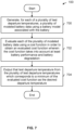
- Figure 1 is a flowchart illustrating an embodiment of a process to determine a desired departure temperature and get a battery in a vehicle to that desired departure temperature.
- the vehicle may be an electric car, an electric aircraft, etc.
- the process is performed while the vehicle is being charged at a charging station.
- a desired departure temperature for a battery, having a temperature, in a vehicle is determined based at least in part on trip information associated with a trip.
- the trip may be an upcoming or next trip for the vehicle (e.g., an electric car, electric aircraft, etc.) and the desired departure temperature is calculated or otherwise determined before that trip begins.
- the type(s) of information included in the trip information may vary from embodiment to embodiment.
- the trip information is relatively simple piece of information, such as a (e.g., expected or planned) trip duration, a destination (e.g., where the point of origin is known since the vehicle is at rest), a trip distance, etc.
- a pilot, driver, or passenger e.g., if the vehicle is an autonomous vehicle
- trip information which is used at step 100. Examples are "How long do you plan to fly/drive for your next flight/trip?" "Where are you flying/driving to?” and so on.
- it may be attractive to ask for relatively simple pieces of trip information because the pilot or driver should be able to answer those questions.
- the pilot or driver is asked for the trip information when the vehicle is connected to a charging station and/or at the end of a previous trip (e.g., the night before the next day's trip).
- the passenger In another example where the vehicle is part of a ride service scenario (e.g., where a vehicle is dispatched to pick up and drop off a passenger) and/or an autonomous vehicle scenario (e.g., where the person does not fly or drive the vehicle), the passenger already has to specify a pickup and/or drop off location and so the passenger is already providing the trip information.
- a ride service scenario e.g., where a vehicle is dispatched to pick up and drop off a passenger
- an autonomous vehicle scenario e.g., where the person does not fly or drive the vehicle
- the trip information may include a trip plan (including a flight plan for an aircraft), such as the path the vehicle will take from its current location to the destination.
- the flight or trip information includes speed and/or time information so it is known how fast the vehicle will be flying (e.g., on average or throughout the trip) which may affect battery usage and therefore battery temperature.
- a flight plan includes instances and/or durations where a VTOL aircraft will hover mid-air (e.g., where hovering consumes significantly more power and therefore generates significantly more heat compared to forward flight). More detailed and/or specific trip information may be desirable because it produces a more accurate and/or precise desired departure temperature.
- more detailed and/or specific trip information may enable the temperature controlling system to be used more efficiently. For example, with a more accurate and/or specific desired departure temperature (due to the more detailed and/or specific trip information), the temperature controlling system may have a smaller margin for error which reduces the amount of unnecessary and/or extraneous cooling or heating.
- the trip information includes a trip duration or a trip plan.
- a desired battery temperature range e.g., [- ⁇ , Tmax], [Tmin, ⁇ ], [Tmin, Tmax], etc.
- trip information is used to determine a desired departure temperature (which the battery will then be set to at the time of departure) which will ensure that the battery remains within some desired battery temperature range over the duration of the (upcoming) trip even as the battery warms up due to use during the trip.
- an optimizer in combination with a battery model is used to determine the desired departure temperature. For example, various and/or test desired departure temperatures can be input to the battery model which then models the behavior of the battery (e.g., given the trip information). An optimizer may then examine the outputs of the battery model and optimize some cost function so that the best or optimal desired departure temperature is selected.
- additional factors or inputs may be used at step 100 to calculate or otherwise determine the desired departure temperature.
- state of health information associated with the battery such as cell internal resistances (e.g., the voltage drop of the cell for a given current where this voltage drop represents the energy lost as heat within the battery) and cell capacities (e.g., the lowest charge capacity of any cell in the battery) may be used to determine the desired departure temperature.
- cell internal resistances e.g., the voltage drop of the cell for a given current where this voltage drop represents the energy lost as heat within the battery
- cell capacities e.g., the lowest charge capacity of any cell in the battery
- Unhealthy batteries tend to require higher temperatures to produce maximum power but also heat more quickly so depending upon mission or flight objectives and the specific state of health of a battery, an unhealthy battery may in some cases need a higher departure temperature or a lower departure temperature.
- the battery has one or more built-in and/or internal battery management systems which monitor and/or estimate such health metrics and output these health metrics (e.g., when the vehicle is plugged into a charging station the health metrics are passed to the charging station which in turn can provide them to the appropriate device for the departure and/or takeoff temperature calculation).
- a battery management system obtains all cell internal resistances and capacities so that an accurate simulation and/or optimization can be performed.
- the ambient (e.g., air) temperature and density is used at step 100 in order to better estimate battery temperature during the trip.
- Air density affects the power required for flight, and the ambient temperature affects any cooling or heating driven by a difference in temperature between the battery and the environment.
- a temperature controlling system is used to bring the temperature of the battery towards the desired departure temperature, wherein the vehicle begins the trip with the battery at the desired departure temperature.
- the temperature controlling system does not bring the temperature of the battery entirely or all the way to the desired departure temperature. For example due to time limitations (e.g., the vehicle is fully charged and/or it is time to depart), it may be undesirable to continue heating or cooling the vehicle and it would be preferable (at least in some cases) to stop heating or cooling so that the vehicle can depart.
- the temperature controlling system is part of some infrastructure (e.g., co-located and/or in communication with a charging station that charges the battery) which does not travel with the vehicle to keep weight down.
- the temperature controlling system is equipped with a heating element (e.g., it can blow hot air across the battery, causing the temperature of the battery to go up) and/or a cooling element (e.g., it can blow cold air across the battery, causing the temperature of the battery to go down) which is detachably coupled to the vehicle and/or the battery.
- the temperature controlling system then blows hot or cold air across the battery to bring the battery to (or at least closer to) the specified temperature so that the battery is at the desired departure temperature at the time of departure.
- the battery will be at (or at least closer to) the desired departure temperature and ideally remains within a desired battery temperature range throughout the trip.
- any appropriate temperature controlling system may be used, including ones with different types of thermal conductors such as a liquid thermal conductor, a solid thermal conductor, etc.
- FIG. 1 shows an example where the vehicle is a vertical takeoff and landing (VTOL) aircraft and the temperature controlling system is an external temperature controlling system.
- VTOL vertical takeoff and landing
- FIG. 2 is a diagram illustrating an example of a vertical takeoff and landing (VTOL) aircraft and an external temperature controlling system.
- aircraft 200 is a VTOL aircraft that is on the ground and is being charged (not shown).
- the vertical lift fans (202) would be turned on. The downward thrust produced by the vertical lift fans (202) permits the aircraft to take off and ascend vertically.
- the forward propeller (204) which is mounted or otherwise coupled to the back of the fuselage, is turned on so that the vehicle begins to move forwards. Once the vehicle is moving forwards fast enough, there will be sufficient aerodynamic lift force acting on the wings (206) to keep the aircraft airborne. At that point, the vertical lift fans (202) are turned off while the forward propeller (204) stays on.
- the vehicle can either land vertically using the vertical lift fans (202) or perform a traditional landing, rolling on its wheels (208) once the aircraft touches down.
- controller 210 receives or otherwise inputs the trip information and generates a desired departure temperature.
- controller 210 is also responsible for managing battery charging and/or gets battery state of health information directly from the battery management system.
- the controller or some other entity estimates the trip information based on historic information (e.g., without asking a driver, pilot, or passenger). For example, if the exemplary vehicle tends to make trips to a certain destination, then that historic information (i.e., the previously and frequently visited destination) is used to generate (or be) the trip information which is input to controller 210.
- the desired departure information is passed from controller 210 to temperature controlling system 212 (e.g., a ground or fixed temperature controlling system which stays on the ground and/or remains at some fixed location).
- temperature controlling system 212 e.g., a ground or fixed temperature controlling system which stays on the ground and/or remains at some fixed location.
- the temperature controlling system has hoses or other connectors which are detachably coupled to the vehicle.
- the temperature controlling system will either blow hot air (214) or cold air (216) over the battery to heat or cool the battery, respectively, to bring the battery to the desired departure temperature.
- a measured battery temperature is sent from the battery (220) to the temperature controlling system (212) so that the latter knows whether the battery's temperature needs to go up, down, or remain the same.
- the amount of heat produced by the battery (220) can vary. For example, if the aircraft is hovering or taking off or landing vertically (i.e., and is relying upon the vertical lift fans (202) to keep the aircraft airborne) then more heat may be produced by the batteries compared to when the vertical lift fans are off and the aircraft is moving forwards fast enough so that the aerodynamic lift force on the wings is keeping the aircraft airborne. Similarly, climbing to a higher altitude or flying at higher speeds will produce more heat in the battery. These are just some examples of how different types of maneuvers or flying can affect the amount of heat produced by the battery (and therefore can affect the desired departure temperature which is calculated or otherwise determined from the trip information).
- Figure 3 is a graph illustrating an example of the temperature of a battery in a vehicle before takeoff, during the drip, and after landing.
- the vehicle is an aircraft but naturally in some other embodiments the vehicle is some other type of vehicle (e.g., a car).
- the battery in the vehicle is set to the desired departure temperature (TDDT) prior to takeoff (i.e., during period 300).
- TDDT departure temperature
- the vehicle may be detachably coupled to a temperature controlling system, such as that shown in Figure 2 .
- the battery When the takeoff occurs at 302, the battery is (already) at the desired departure temperature (TDDT).
- TDDT desired departure temperature
- the temperature of the battery gradually increases but always remains between the desired battery temperature range (306), which in this example ranges from Tmin to Tmax, even at landing (308) when the battery temperature tends to be the hottest.
- the desired battery temperature range is open-ended at one extreme (e.g., there is only a Tmin or only a Tmax).
- the battery will operate during the entirety of the trip (i.e., period 304) within some safe and/or desirable battery temperature range (306).
- the battery may operate outside of some desirable battery temperature range during the flight which may be dangerous and force the aircraft to land early. This problem may be more noticeable and/or especially acute during extremely hot weather (e.g., at or above 100°F) when the battery is operating in a high ambient temperature environment.
- extremely cold weather e.g. at or below 0°F
- the battery temperature could decrease in flight outside of acceptable range if the takeoff battery temperature was not high enough.
- FIG 4 is a flowchart illustrating an embodiment of a process to determine a desired departure temperature using a trip duration and an estimation function. According to the invention, step 100 in Figure 1 is performed using the example process shown here.
- ⁇ T (310) in Figure 3 shows an example of a change in battery temperature (e.g., that is estimated or otherwise determined at step 400).
- the estimation function is a multivariable function and/or f ( t ) is selected based at least in part on one or more other inputs. For example, depending upon the ambient temperature, an appropriate f ( t ) may be selected. To put it another way, depending upon the ambient temperature, the change in battery temperature will vary even if the trip duration is the same.
- the desired departure temperature is determined using the change in battery temperature associated with the trip and a desired battery temperature range. Step 402 will attempt, where possible, to keep the battery temperature within the desired battery temperature range over the course of the entire trip.
- step 402 if the change in battery temperature (e.g., determined at step 400) is less than the desired battery temperature range (where in this example it is assumed there is a Tmin and a Tmax), then the desired departure temperature is determined so that the temperature margin at takeoff (e.g., TDDT - Tmin) equals the temperature margin at landing (e.g., Tmax - (TDDT + ⁇ T)).
- the temperature margin at takeoff e.g., TDDT - Tmin
- the temperature margin at landing e.g., Tmax - (TDDT + ⁇ T)
- this approach may leave some temperature margin at landing (and overheating may be more of a concern than operating at too cold of a temperature) while not requiring the temperature controlling system to cool the battery all the way down to Tmin.
- cooling the battery down to some temperature above Tmin consumes less power (at the temperature controlling system) than cooling the battery all the way down to Tmin while still providing some margin on the upper temperature range at landing.
- FIG. 5 is a flowchart illustrating an embodiment of a process to determine a desired departure temperature using a trip duration and an estimation function. According to the invention, step 100 in Figure 1 is performed using the example process shown here.
- a change in battery temperature associated with the trip is determined using a trip plan and an estimation function that inputs the trip plan, wherein the trip information includes the trip plan.
- the trip plan may be a flight plan.
- the flight plan includes speed(s) and/or time(s) so that some sense of how hard the battery is being drawn upon is obtained.
- a trip plan (e.g., a flight plan) is fed into a simulator (e.g., flight simulator which inputs desired forces and moments and outputs desired thrusts or other commands for the motors and/or propellers) and the outputs from the simulator are passed to the estimator which uses the simulator outputs to estimate the change in battery temperature. For example, by using a simulator of how the vehicle will respond, a more accurate desired departure temperature can be determined.
- a simulator e.g., flight simulator which inputs desired forces and moments and outputs desired thrusts or other commands for the motors and/or propellers
- the desired departure temperature is determined using the change in battery temperature associated with the trip and a desired battery temperature range. For example, some of the examples described above with respect to step 402 in Figure 4 may be used.
- a battery model and an optimizer are used to determine a desired departure temperature.
- the following figures describe one such example.
- FIG. 6A is a diagram illustrating an example of a battery model and an optimizer which are used to determine a desired departure temperature.
- a battery model models how a battery responds or behaves given certain input parameters.
- battery model 600 inputs battery state of health (SOH) information (e.g., describing or representing the age or wear of the battery, generally indicating how "healthy" the battery is, etc.), the ambient (e.g., air) temperature, and trip information.
- SOH battery state of health
- the battery state of health information may be reported by a built-in battery management system which monitors and/or estimates the current health of the battery. This information may be communicated from the built-in battery management system to a battery charger, and from the battery charger to the system shown here.
- the battery model (600) will model the state and/or behavior of the battery for a variety of test departure temperatures. For each test departure temperature, modeled battery state and/or behavior information is sent from the battery model (600) to the optimizer (602).
- the optimizer evaluates a cost function using the modeled information and selects the test departure temperature which has the lowest (evaluated) cost function value. For example, the cost function may weigh the benefits of a warmer battery (e.g., better performance) against the drawbacks of a warmer battery (e.g., tends to degrade faster) and the evaluated cost function is a representation of that pro-con assessment for a given test departure temperature.
- the cost function takes into account things like time to departure (e.g., which may be included in trip information), time to charge (e.g., which may be reported by the charging station), and/or time to heat/cool (e.g., estimated for a given desired departure temperature).
- the desired departure temperatures which have a time to heat/cool that is greater than the time to charge would be penalized (e.g., have a higher evaluated cost function) more than the desired departure temperatures which have a time to heat/cool that is less than the time to charge.
- the departure temperature selected attempts to satisfy the acceptable temperature window but not necessarily the desirable temperature range or window.
- the departure temperature selected or determines may be as hot as possible so as not to violate a constraint specified by acceptable temperature window (e.g., in cooling limited situations) or as cold as possible per the acceptable temperature window (e.g., heating limited situations).
- a cost function takes into account an amount of energy consumed by the temperature controlling system to bring a battery to a given desired departure temperature. For example, if the performance and/or degradation of a battery varies only slightly across a range of temperatures then it may not make sense to bring the battery to heat or cool the battery to a more extreme temperature from its current temperature.
- the battery state and/or behavior information generated by the battery model varies with and/or is a function of time.
- some battery model embodiments are able to model the behavior of the battery over the course of the trip. In some examples, this ability to generate battery state information which is a function of time (e.g., over the course of the trip) permits better quality desired departure temperatures to be generated.
- the following figure shows an example of a cost function generated by optimizer 602.
- Figure 6B is a graph illustrating an example of an evaluated cost function.
- cost function 650 is an example of an evaluated cost function which is generated by optimizer 602 in Figure 6A for the modeled battery state and/or behavior information generated from the various test departure temperatures.
- local minimum 652 has the lowest cost associated with it. As such, the test departure temperature corresponding to local minimum 652 is output as the desired departure temperature (TDDT).
- TDDT desired departure temperature
- Figure 7 is a flowchart illustrating an embodiment of a process to determine a desired departure temperature using a battery model and cost function.
- step 100 in Figure 1 is performed using the example process shown here.
- a plurality of modeled battery data is generated using a battery model associated with the battery. See, for example, battery model 600 in Figure 6A .
- corresponding modeled battery data e.g., battery state and/or behavior information output by the battery model
- each of the plurality of modeled battery data is evaluated using a cost function in order to obtain an evaluated cost function wherein the cost function takes into account at least battery performance and battery degradation.
- the cost function takes into account at least battery performance and battery degradation.
- warmer temperatures tend to be better for battery performance (which is good) but also tend to degrade the battery faster (which is bad).
- Evaluated cost function 650 in Figure 6B shows an example of an evaluated cost function.
- test departure temperature from the plurality of test departure temperatures which corresponds to a minimum of the evaluated cost function is output as the desired departure temperature. See, for example, Figure 6B where the test departure temperature which corresponds to local minimum 652 is output as the desired departure temperature.
- Figure 8 is a diagram illustrating an example of a vehicle where the departure time is known ahead of time and the temperature controlling system does not begin heating or cooling the battery until the departure is imminent.
- the vehicle is an aircraft but naturally the techniques described herein may be applied toward other types of vehicles (e.g., cars).
- the aircraft lands at 6:30 pm (800) with a battery temperature of Tland.
- a desired departure temperature in this example, a desired takeoff temperature, TDTOT
- TDTOT desired takeoff temperature
- the temperature controlling system could begin cooling the battery to the calculated TDTOT, the aircraft is not going to take off until 8:00 am the next morning (802). If the temperature controlling system began cooling immediately (e.g., soon after landing), the temperature controlling system will have to work from approximately 6:30 pm to 8:00 am. However, it may not take that long to bring the battery down to TDTOT and therefore starting the temperature controlling system may therefore be a waste of power.
- at higher temperature battery generally tends to degrade faster; therefore, in some scenarios it may be helpful to cool the battery down first so that it can spend more time at lower temperature to preserve battery life.
- the system will (e.g., based on the desired departure temperature and the known takeoff time) estimate or otherwise determine a time at which to start the temperature controlling system so that the battery will be at the desired departure temperature at the takeoff time but without unnecessarily starting the temperature controlling system too soon. In this example, that time is determined to be 7:30 am (804).
- the temperature controlling system is off (e.g., to conserve power).
- the temperature controlling system is on in order to bring the temperature of the battery to the desired departure temperature.
- Figure 9 is a flowchart illustrating an embodiment of a process to get a battery in a vehicle to a desired departure temperature, including by determining a start time for a temperature controlling system.
- Figure 9 is related to Figure 1 and for convenience related and/or similar steps are indicated using the same and/or similar reference numbers.
- a desired departure temperature for a battery, having a temperature, in a vehicle is determined based at least in part on trip information associated with a trip, wherein the trip information includes a departure time. For example, suppose a vehicle arrives at some destination and is plugged into a charging station. At that time, the charging station or some related interface (e.g., on the user's smartphone) may ask the driver or pilot when they plan to depart. In some embodiments, this departure time is also used to manage or otherwise perform charging.
- the departure time is not specified by a driver or pilot but rather is determined based on historic information. For example, if the driver or pilot has a regular commute or some routine, the departure time may be determined based on historic information (e.g., they tend to leave around the same time on weekdays). Any appropriate estimation technique may be used.
- a start time to start a temperature controlling system is determined based at least in part on the departure time and the desired departure temperature.
- the temperature controlling system may be able to heat or cool the battery at a rate of d degrees per minute and based on the current temperature of the battery and the departure time, the start time may be calculated.
- step 900 includes periodically and/or continually performing a check of "Should the temperature controlling system start now?" given the current temperature, the desired departure temperature, and the heating or cooling rate of the temperature controlling system (e.g., a rate of d degrees per minute). For example, this may better account for and/or be more adaptable to the temperature change of the battery (e.g., as the battery cools throughout the night, assuming it is hot at landing).
- the temperature controlling system is used to get the battery to the desired departure temperature, wherein the vehicle begins the trip with the battery at the desired departure temperature and the temperature controlling system is started at the start time. As described above, this saves power at the temperature controlling system since the temperature controlling system is not running unnecessarily.
- a battery charging time (e.g., how long it will take for the battery in the vehicle to be charged) is received from a charging station to which the vehicle is detachably coupled and the departure time is determined based at least in part on the battery charging time.
- a battery charging time is less than the amount of time it would take to bring the battery down (e.g., completely or entirely) to the desired departure temperature, even if the temperature controlling system started immediately.
- the start time determined at step 900 is "immediately" and because it is undesirable to hold a fully-charged vehicle simply to finish bringing the battery (e.g., completely or entirely) to the desired departure temperature
- step 102' includes stopping the temperature controlling system when a charging station finishes charging the battery (e.g., that is being heated or cooled) in the vehicle (e.g., assuming that the battery is sufficiently cooled or heated such that some acceptable battery temperature range is not violated).
- the battery charging time is greater than the amount of time it would take to bring the battery down (e.g., completely or entirely) to the desired departure temperature and a start time in the future is determined.
Landscapes
- Engineering & Computer Science (AREA)
- Power Engineering (AREA)
- Transportation (AREA)
- Mechanical Engineering (AREA)
- Life Sciences & Earth Sciences (AREA)
- Sustainable Development (AREA)
- Sustainable Energy (AREA)
- Chemical & Material Sciences (AREA)
- Manufacturing & Machinery (AREA)
- Chemical Kinetics & Catalysis (AREA)
- Electrochemistry (AREA)
- General Chemical & Material Sciences (AREA)
- Automation & Control Theory (AREA)
- Electric Propulsion And Braking For Vehicles (AREA)
- Secondary Cells (AREA)
- Charge And Discharge Circuits For Batteries Or The Like (AREA)
Description
- Vehicles, such as cars and aircraft, are becoming increasingly powered by batteries. Techniques to better manage and/or utilize batteries in vehicles would be desirable. For example, it would be desirable if such techniques could prolong the lifetime of such batteries and/or produce better performing batteries.
-
US 2017/217328 A1 describes a system, which includes an on-board charger that receives energy from an external power source and a battery having a state of charge (SOC) and a battery temperature. The system also includes a battery heater that converts electrical energy into thermal energy (heat) for increasing the battery temperature. The system also includes a battery management system (BMS) that determines or detects a current SOC of the battery and a current battery temperature. The system also includes an electronic control unit (ECU) coupled to the on-board charger and to the BMS. The ECU controls the on-board charger to distribute energy to the battery and to the battery heater to cause the SOC to remain above a SOC threshold and to cause the battery temperature to remain above a battery temperature threshold based on the current SOC and the current battery temperature. -
US 2016/059733 A1 describes systems and methods for determining battery heating conditions and pre-heating lead times of at least a minute or more, based on input parameters and sets of input parameters, to predictively and dynamically heat a secondary battery so that the battery has a specific power output and performance level when used in an electric or hybrid vehicle application. -
US 2012/158228 A1 describes a method and system for conditioning an energy storage system (ESS) for a vehicle, like a high-voltage battery or a fuel cell used for vehicle propulsion. It may be detrimental for a high-voltage battery in a parked vehicle to be exposed to extreme temperatures for an extended period of time. Thus, the method and system may be used to condition such a battery - for example, by heating it up if it is too cold or by cooling it down if it is too hot - so that the performance, durability, lifespan and/or other aspects of the battery are improved. The method predicts if the battery will need conditioning the next time the vehicle is parked and, if such conditioning is needed, then the method predicts if the battery has sufficient charge to perform this conditioning. If the charge appears insufficient, then the method operates an energy generator that provides additional charge to the battery in anticipation of the needed conditioning. -
EP 2 662 949 A1 describes a charging control device, which includes: a remaining charge acquisition unit that obtains a remaining charge of a rechargeable battery for an electric vehicle; a lifespan information acquisition unit that obtains lifespan information expressing a degree of deterioration of the rechargeable battery; an environmental information acquisition unit that obtains information indicating a peripheral temperature of the electric vehicle; and a charging plan updating unit that creates a charging plan including a target remaining charge of the rechargeable battery and a charging process up to achievement of the target remaining charge. The charging plan updating unit determines whether or not to create the charging plan in consideration of the deterioration of the rechargeable battery on the basis of the lifespan information, and after determining to take the deterioration of the rechargeable battery into consideration, creates the charging plan such that when the temperature is equal to or higher than a predetermined value, the remaining charge of the rechargeable battery is maintained at or below a predetermined value for as long as possible during a charging period. -
JP 2017117614 A -
US 2014180519 A1 describes a vehicle that incorporates an engine to which an engine-related component is attached, a battery charged with electric power supplied from an external power supply, and an electric motor as a driving source to which electric power is supplied from the battery. An ECU causes at least one of the engine-related component and the battery to be heated, using the electric power supplied from outside while the electric power is being supplied from outside, in accordance with a distance over which the vehicle can run by driving the electric motor alone and a distance to a destination. - According to an aspect of the present invention, there is provided a system according to any of claims 1 to 5.
- According to another aspect of the present invention, there is provided a method according to any of claims 6 to 10.
- According to a further aspect of the present invention, there is provided a computer program product according to any of claims 11 to 14.
- Various embodiments and examples of the invention are disclosed in the following detailed description and the accompanying drawings.
-
Figure 1 is a flowchart illustrating an embodiment of a process to determine a desired departure temperature and get a battery in a vehicle to that desired departure temperature. -
Figure 2 is a diagram illustrating an example of a vertical takeoff and landing (VTOL) aircraft and an external temperature controlling system. -
Figure 3 is a graph illustrating an example of the temperature of a battery in a vehicle before takeoff, during the trip, and after landing. -
Figure 4 is a flowchart illustrating an embodiment of a process to determine a desired departure temperature using a trip duration and an estimation function. -
Figure 5 is a flowchart illustrating an embodiment of a process to determine a desired departure temperature using a trip duration and an estimation function. -
Figure 6A is a diagram illustrating an example of a battery model and an optimizer which are used to determine a desired departure temperature. -
Figure 6B is a graph illustrating an example of an evaluated cost function. -
Figure 7 is a flowchart illustrating an embodiment of a process to determine a desired departure temperature using a battery model and cost function. -
Figure 8 is a diagram illustrating an example of a vehicle where the departure time is known ahead of time and the temperature controlling system does not begin heating or cooling the battery until the departure is imminent. -
Figure 9 is a flowchart illustrating an embodiment of a process to get a battery in a vehicle to a desired departure temperature, including by determining a start time for a temperature controlling system. - The invention can be implemented in numerous ways, including as a process; a system, a computer program product comprised on a computer readable storage medium; and/or a processor, such as a processor configured to execute instructions stored on and/or provided by a memory coupled to the processor. In this specification, these implementations, or any other form that the invention may take, may be referred to as techniques. In general, the order of the steps of disclosed processes may be altered within the scope of the invention. Unless stated otherwise, a component such as a processor or a memory described as being configured to perform a task may be implemented as a general component that is temporarily configured to perform the task at a given time or a specific component that is manufactured to perform the task. As used herein, the term 'processor' refers to one or more devices, circuits, and/or processing cores configured to process data, such as computer program instructions.
- A detailed description of one or more embodiments of the invention is provided below along with accompanying figures that illustrate the principles of the invention. The invention is described in connection with such embodiments, but the invention is not limited to any embodiment. The scope of the invention is limited only by the claims and the invention encompasses numerous modifications. Numerous specific details are set forth in the following description in order to provide a thorough understanding of the invention. These details are provided for the purpose of example and the invention may be practiced according to the claims without some or all of these specific details. For the purpose of clarity, technical material that is known in the technical fields related to the invention has not been described in detail so that the invention is not unnecessarily obscured.
- Various examples to determine a desired departure temperature and bring the temperature of the battery closer towards (and sometimes to) the desired departure temperature at a departure time are described herein. Batteries tend to have higher performance (e.g., higher power output, a longer range, etc.) when they are warm. However, the downside of a warmer battery is that batteries generally tend to degrade more quickly the warmer they are. In some embodiments, a desired departure temperature is calculated and the battery is set to (or at least closer to) that temperature at the time of the vehicle's departure (e.g., at the time of takeoff in the case of an aircraft). This can strike a balance between battery performance and degradation and/or ensure that the temperature of the battery remains within some desired temperature range during the entirety of a trip.
-
Figure 1 is a flowchart illustrating an embodiment of a process to determine a desired departure temperature and get a battery in a vehicle to that desired departure temperature. In various examples, the vehicle may be an electric car, an electric aircraft, etc. In some examples, the process is performed while the vehicle is being charged at a charging station. - At 100, a desired departure temperature for a battery, having a temperature, in a vehicle is determined based at least in part on trip information associated with a trip. For example, the trip may be an upcoming or next trip for the vehicle (e.g., an electric car, electric aircraft, etc.) and the desired departure temperature is calculated or otherwise determined before that trip begins.
- The type(s) of information included in the trip information may vary from embodiment to embodiment. In some embodiments, the trip information is relatively simple piece of information, such as a (e.g., expected or planned) trip duration, a destination (e.g., where the point of origin is known since the vehicle is at rest), a trip distance, etc.
- In some examples, a pilot, driver, or passenger (e.g., if the vehicle is an autonomous vehicle) is asked for trip information which is used at
step 100. Examples are "How long do you plan to fly/drive for your next flight/trip?" "Where are you flying/driving to?" and so on. In such embodiments, it may be attractive to ask for relatively simple pieces of trip information (such as those examples described above) because the pilot or driver should be able to answer those questions. For example, in one scenario where the pilot or driver owns and operates the vehicle, the pilot or driver is asked for the trip information when the vehicle is connected to a charging station and/or at the end of a previous trip (e.g., the night before the next day's trip). In another example where the vehicle is part of a ride service scenario (e.g., where a vehicle is dispatched to pick up and drop off a passenger) and/or an autonomous vehicle scenario (e.g., where the person does not fly or drive the vehicle), the passenger already has to specify a pickup and/or drop off location and so the passenger is already providing the trip information. - In some embodiments, more detailed and/or specific information is included in or otherwise comprises the trip information. For example, the trip information may include a trip plan (including a flight plan for an aircraft), such as the path the vehicle will take from its current location to the destination. In some examples, the flight or trip information includes speed and/or time information so it is known how fast the vehicle will be flying (e.g., on average or throughout the trip) which may affect battery usage and therefore battery temperature. In some examples, a flight plan includes instances and/or durations where a VTOL aircraft will hover mid-air (e.g., where hovering consumes significantly more power and therefore generates significantly more heat compared to forward flight). More detailed and/or specific trip information may be desirable because it produces a more accurate and/or precise desired departure temperature. In some cases, more detailed and/or specific trip information may enable the temperature controlling system to be used more efficiently. For example, with a more accurate and/or specific desired departure temperature (due to the more detailed and/or specific trip information), the temperature controlling system may have a smaller margin for error which reduces the amount of unnecessary and/or extraneous cooling or heating.
- According to the invention, the trip information includes a trip duration or a trip plan.
- According to the invention, it is desirable for batteries to operate within a desired battery temperature range (e.g., [-∞, Tmax], [Tmin, ∞], [Tmin, Tmax], etc.) over the course of a trip. For example, if a battery becomes too hot, it may be dangerous to use. To that end, according to the invention, trip information is used to determine a desired departure temperature (which the battery will then be set to at the time of departure) which will ensure that the battery remains within some desired battery temperature range over the duration of the (upcoming) trip even as the battery warms up due to use during the trip.
- In some examples, an optimizer in combination with a battery model is used to determine the desired departure temperature. For example, various and/or test desired departure temperatures can be input to the battery model which then models the behavior of the battery (e.g., given the trip information). An optimizer may then examine the outputs of the battery model and optimize some cost function so that the best or optimal desired departure temperature is selected.
- In some embodiments, additional factors or inputs may be used at
step 100 to calculate or otherwise determine the desired departure temperature. For example, state of health information associated with the battery (cell(s)) such as cell internal resistances (e.g., the voltage drop of the cell for a given current where this voltage drop represents the energy lost as heat within the battery) and cell capacities (e.g., the lowest charge capacity of any cell in the battery) may be used to determine the desired departure temperature. Generally speaking, the health of a battery (e.g., represented or otherwise measured by the health metrics) affects the temperature-dependent performance of the battery as well as the temperature-dependent degradation of the battery. Unhealthy batteries tend to require higher temperatures to produce maximum power but also heat more quickly so depending upon mission or flight objectives and the specific state of health of a battery, an unhealthy battery may in some cases need a higher departure temperature or a lower departure temperature. In some examples, the battery has one or more built-in and/or internal battery management systems which monitor and/or estimate such health metrics and output these health metrics (e.g., when the vehicle is plugged into a charging station the health metrics are passed to the charging station which in turn can provide them to the appropriate device for the departure and/or takeoff temperature calculation). In some examples, such a battery management system obtains all cell internal resistances and capacities so that an accurate simulation and/or optimization can be performed. - In some examples, the ambient (e.g., air) temperature and density is used at
step 100 in order to better estimate battery temperature during the trip. Air density affects the power required for flight, and the ambient temperature affects any cooling or heating driven by a difference in temperature between the battery and the environment. - At 102, a temperature controlling system is used to bring the temperature of the battery towards the desired departure temperature, wherein the vehicle begins the trip with the battery at the desired departure temperature. In some examples, the temperature controlling system does not bring the temperature of the battery entirely or all the way to the desired departure temperature. For example due to time limitations (e.g., the vehicle is fully charged and/or it is time to depart), it may be undesirable to continue heating or cooling the vehicle and it would be preferable (at least in some cases) to stop heating or cooling so that the vehicle can depart.
- In some examples, the temperature controlling system is part of some infrastructure (e.g., co-located and/or in communication with a charging station that charges the battery) which does not travel with the vehicle to keep weight down. In one example, the temperature controlling system is equipped with a heating element (e.g., it can blow hot air across the battery, causing the temperature of the battery to go up) and/or a cooling element (e.g., it can blow cold air across the battery, causing the temperature of the battery to go down) which is detachably coupled to the vehicle and/or the battery. The temperature controlling system then blows hot or cold air across the battery to bring the battery to (or at least closer to) the specified temperature so that the battery is at the desired departure temperature at the time of departure. Then, when the vehicle departs for the trip (e.g., takes off, drives off, etc.) the battery will be at (or at least closer to) the desired departure temperature and ideally remains within a desired battery temperature range throughout the trip. Naturally, any appropriate temperature controlling system may be used, including ones with different types of thermal conductors such as a liquid thermal conductor, a solid thermal conductor, etc.
- It may be helpful to show a system which performs the process of
Figure 1 . The following figure shows an example where the vehicle is a vertical takeoff and landing (VTOL) aircraft and the temperature controlling system is an external temperature controlling system. -
Figure 2 is a diagram illustrating an example of a vertical takeoff and landing (VTOL) aircraft and an external temperature controlling system. In the example shown,aircraft 200 is a VTOL aircraft that is on the ground and is being charged (not shown). To take off, the vertical lift fans (202) would be turned on. The downward thrust produced by the vertical lift fans (202) permits the aircraft to take off and ascend vertically. Once airborne, the forward propeller (204), which is mounted or otherwise coupled to the back of the fuselage, is turned on so that the vehicle begins to move forwards. Once the vehicle is moving forwards fast enough, there will be sufficient aerodynamic lift force acting on the wings (206) to keep the aircraft airborne. At that point, the vertical lift fans (202) are turned off while the forward propeller (204) stays on. To land, the vehicle can either land vertically using the vertical lift fans (202) or perform a traditional landing, rolling on its wheels (208) once the aircraft touches down. - In this example,
controller 210 receives or otherwise inputs the trip information and generates a desired departure temperature. In some embodiments,controller 210 is also responsible for managing battery charging and/or gets battery state of health information directly from the battery management system. In addition to the examples above where a driver, pilot, or passenger provides the trip information (which is input to and used by controller 210), in some examples the controller or some other entity estimates the trip information based on historic information (e.g., without asking a driver, pilot, or passenger). For example, if the exemplary vehicle tends to make trips to a certain destination, then that historic information (i.e., the previously and frequently visited destination) is used to generate (or be) the trip information which is input tocontroller 210. - The desired departure information is passed from
controller 210 to temperature controlling system 212 (e.g., a ground or fixed temperature controlling system which stays on the ground and/or remains at some fixed location). In this example, the temperature controlling system has hoses or other connectors which are detachably coupled to the vehicle. Depending upon whether the battery (220) needs to be heated or cooled, the temperature controlling system will either blow hot air (214) or cold air (216) over the battery to heat or cool the battery, respectively, to bring the battery to the desired departure temperature. A measured battery temperature is sent from the battery (220) to the temperature controlling system (212) so that the latter knows whether the battery's temperature needs to go up, down, or remain the same. - As will be described in more detail below, depending upon the type of maneuvers or flying the exemplary vehicle is performing, the amount of heat produced by the battery (220) can vary. For example, if the aircraft is hovering or taking off or landing vertically (i.e., and is relying upon the vertical lift fans (202) to keep the aircraft airborne) then more heat may be produced by the batteries compared to when the vertical lift fans are off and the aircraft is moving forwards fast enough so that the aerodynamic lift force on the wings is keeping the aircraft airborne. Similarly, climbing to a higher altitude or flying at higher speeds will produce more heat in the battery. These are just some examples of how different types of maneuvers or flying can affect the amount of heat produced by the battery (and therefore can affect the desired departure temperature which is calculated or otherwise determined from the trip information).
-
Figure 3 is a graph illustrating an example of the temperature of a battery in a vehicle before takeoff, during the drip, and after landing. In this example, the vehicle is an aircraft but naturally in some other embodiments the vehicle is some other type of vehicle (e.g., a car). In the example shown, the battery in the vehicle is set to the desired departure temperature (TDDT) prior to takeoff (i.e., during period 300). For example, the vehicle may be detachably coupled to a temperature controlling system, such as that shown inFigure 2 . - When the takeoff occurs at 302, the battery is (already) at the desired departure temperature (TDDT). During the flight (i.e., period 304), the temperature of the battery gradually increases but always remains between the desired battery temperature range (306), which in this example ranges from Tmin to Tmax, even at landing (308) when the battery temperature tends to be the hottest. In some other embodiments, the desired battery temperature range is open-ended at one extreme (e.g., there is only a Tmin or only a Tmax).
- As shown here, calculating a desired departure temperature and getting the battery to that temperature at the time of departure, the battery will operate during the entirety of the trip (i.e., period 304) within some safe and/or desirable battery temperature range (306). In contrast, if the techniques described herein are not applied and the battery is at some ambient or room temperature at the time of departure, the battery may operate outside of some desirable battery temperature range during the flight which may be dangerous and force the aircraft to land early. This problem may be more noticeable and/or especially acute during extremely hot weather (e.g., at or above 100°F) when the battery is operating in a high ambient temperature environment. Similarly, in extremely cold weather (e.g. at or below 0°F) the battery temperature could decrease in flight outside of acceptable range if the takeoff battery temperature was not high enough.
- The following figure describes this example more generally and/or formally in a flowchart.
-
Figure 4 is a flowchart illustrating an embodiment of a process to determine a desired departure temperature using a trip duration and an estimation function. According to the invention,step 100 inFigure 1 is performed using the example process shown here. - At 400, a change in battery temperature associated with the trip is determined using a trip duration and an estimation function that inputs the trip duration, wherein the trip information includes the trip duration. That is, ΔT =f(ttrip_duration) where ΔT is the change in battery temperature over the course of the trip, f(t) is the estimation function (e.g., which inputs a unit of time and outputs a unit of temperature such as °F, °C, etc.), and ttrip_duration is the trip duration (e.g., in minutes, hours, etc.). ΔT (310) in
Figure 3 shows an example of a change in battery temperature (e.g., that is estimated or otherwise determined at step 400). - In some examples, the estimation function is a multivariable function and/or f(t) is selected based at least in part on one or more other inputs. For example, depending upon the ambient temperature, an appropriate f(t) may be selected. To put it another way, depending upon the ambient temperature, the change in battery temperature will vary even if the trip duration is the same.
- At 402, the desired departure temperature is determined using the change in battery temperature associated with the trip and a desired battery temperature range. Step 402 will attempt, where possible, to keep the battery temperature within the desired battery temperature range over the course of the entire trip.
- In one example of
step 402, if the change in battery temperature (e.g., determined at step 400) is less than the desired battery temperature range (where in this example it is assumed there is a Tmin and a Tmax), then the desired departure temperature is determined so that the temperature margin at takeoff (e.g., TDDT - Tmin) equals the temperature margin at landing (e.g., Tmax - (TDDT + ΔT)). For example, this approach may leave some temperature margin at landing (and overheating may be more of a concern than operating at too cold of a temperature) while not requiring the temperature controlling system to cool the battery all the way down to Tmin. To put it another way, cooling the battery down to some temperature above Tmin consumes less power (at the temperature controlling system) than cooling the battery all the way down to Tmin while still providing some margin on the upper temperature range at landing. -
Figure 5 is a flowchart illustrating an embodiment of a process to determine a desired departure temperature using a trip duration and an estimation function. According to the invention,step 100 inFigure 1 is performed using the example process shown here. - At 500, a change in battery temperature associated with the trip is determined using a trip plan and an estimation function that inputs the trip plan, wherein the trip information includes the trip plan. For example, if the vehicle is an aircraft then the trip plan may be a flight plan. In some examples, the flight plan includes speed(s) and/or time(s) so that some sense of how hard the battery is being drawn upon is obtained.
- In some examples, a trip plan (e.g., a flight plan) is fed into a simulator (e.g., flight simulator which inputs desired forces and moments and outputs desired thrusts or other commands for the motors and/or propellers) and the outputs from the simulator are passed to the estimator which uses the simulator outputs to estimate the change in battery temperature. For example, by using a simulator of how the vehicle will respond, a more accurate desired departure temperature can be determined.
- At 502, the desired departure temperature is determined using the change in battery temperature associated with the trip and a desired battery temperature range. For example, some of the examples described above with respect to step 402 in
Figure 4 may be used. - In some examples, a battery model and an optimizer are used to determine a desired departure temperature. The following figures describe one such example.
-
Figure 6A is a diagram illustrating an example of a battery model and an optimizer which are used to determine a desired departure temperature. In the example shown, a battery model models how a battery responds or behaves given certain input parameters. In this example,battery model 600 inputs battery state of health (SOH) information (e.g., describing or representing the age or wear of the battery, generally indicating how "healthy" the battery is, etc.), the ambient (e.g., air) temperature, and trip information. For example, the battery state of health information may be reported by a built-in battery management system which monitors and/or estimates the current health of the battery. This information may be communicated from the built-in battery management system to a battery charger, and from the battery charger to the system shown here. - With the specified inputs or parameters described above, the battery model (600) will model the state and/or behavior of the battery for a variety of test departure temperatures. For each test departure temperature, modeled battery state and/or behavior information is sent from the battery model (600) to the optimizer (602). The optimizer evaluates a cost function using the modeled information and selects the test departure temperature which has the lowest (evaluated) cost function value. For example, the cost function may weigh the benefits of a warmer battery (e.g., better performance) against the drawbacks of a warmer battery (e.g., tends to degrade faster) and the evaluated cost function is a representation of that pro-con assessment for a given test departure temperature.
- In some applications it is undesirable for a vehicle to wait around simply for a temperature controlling system to bring the battery in the vehicle to the desired departure temperature (e.g., the battery is fully charged; the driver, pilot, or passenger wants to depart and is waiting; etc.). To account for this, in some examples, the cost function takes into account things like time to departure (e.g., which may be included in trip information), time to charge (e.g., which may be reported by the charging station), and/or time to heat/cool (e.g., estimated for a given desired departure temperature). For example, if the time to departure is "as soon as charging is done" (or is a time or duration earlier or shorter than the time to charge), then the desired departure temperatures which have a time to heat/cool that is greater than the time to charge would be penalized (e.g., have a higher evaluated cost function) more than the desired departure temperatures which have a time to heat/cool that is less than the time to charge.
- It some examples there is an acceptable temperature window or range that is different (e.g., wider) than the desirable temperature range or window. In one example where it is desirable to depart as soon as possible, the departure temperature selected attempts to satisfy the acceptable temperature window but not necessarily the desirable temperature range or window. For example, the departure temperature selected or determines may be as hot as possible so as not to violate a constraint specified by acceptable temperature window (e.g., in cooling limited situations) or as cold as possible per the acceptable temperature window (e.g., heating limited situations).
- In some embodiments, a cost function takes into account an amount of energy consumed by the temperature controlling system to bring a battery to a given desired departure temperature. For example, if the performance and/or degradation of a battery varies only slightly across a range of temperatures then it may not make sense to bring the battery to heat or cool the battery to a more extreme temperature from its current temperature.
- In some examples, the battery state and/or behavior information generated by the battery model varies with and/or is a function of time. For example, with more detailed and/or specific trip information, some battery model embodiments are able to model the behavior of the battery over the course of the trip. In some examples, this ability to generate battery state information which is a function of time (e.g., over the course of the trip) permits better quality desired departure temperatures to be generated.
- The following figure shows an example of a cost function generated by
optimizer 602. -
Figure 6B is a graph illustrating an example of an evaluated cost function. In the example shown,cost function 650 is an example of an evaluated cost function which is generated byoptimizer 602 inFigure 6A for the modeled battery state and/or behavior information generated from the various test departure temperatures. In this example,local minimum 652 has the lowest cost associated with it. As such, the test departure temperature corresponding tolocal minimum 652 is output as the desired departure temperature (TDDT). - The following figure describes this example more generally and/or formally in a flowchart.
-
Figure 7 is a flowchart illustrating an embodiment of a process to determine a desired departure temperature using a battery model and cost function. In some embodiments,step 100 inFigure 1 is performed using the example process shown here. - At 700, for each of a plurality of test departure temperatures, a plurality of modeled battery data is generated using a battery model associated with the battery. See, for example,
battery model 600 inFigure 6A . For each test departure temperature in the plurality of test departure temperatures (e.g., T0, T1, etc.), corresponding modeled battery data (e.g., battery state and/or behavior information output by the battery model) is produced. - At 702, each of the plurality of modeled battery data is evaluated using a cost function in order to obtain an evaluated cost function wherein the cost function takes into account at least battery performance and battery degradation. As described above, warmer temperatures tend to be better for battery performance (which is good) but also tend to degrade the battery faster (which is bad). Evaluated
cost function 650 inFigure 6B shows an example of an evaluated cost function. - At 704, that test departure temperature from the plurality of test departure temperatures which corresponds to a minimum of the evaluated cost function is output as the desired departure temperature. See, for example,
Figure 6B where the test departure temperature which corresponds tolocal minimum 652 is output as the desired departure temperature. - The following figure describes an example where the departure time is known ahead of time and this information is used to conserve power at the temperature controlling system. For brevity, the following examples are not shown in combination with the above examples but it is understood that any combination of the techniques described herein may be used.
-
Figure 8 is a diagram illustrating an example of a vehicle where the departure time is known ahead of time and the temperature controlling system does not begin heating or cooling the battery until the departure is imminent. In this example, the vehicle is an aircraft but naturally the techniques described herein may be applied toward other types of vehicles (e.g., cars). - In this example, the aircraft lands at 6:30 pm (800) with a battery temperature of Tland. A desired departure temperature (in this example, a desired takeoff temperature, TDTOT) is calculated or otherwise determined upon landing and the resulting TDTOT is (strictly) less than Tland. Although the temperature controlling system could begin cooling the battery to the calculated TDTOT, the aircraft is not going to take off until 8:00 am the next morning (802). If the temperature controlling system began cooling immediately (e.g., soon after landing), the temperature controlling system will have to work from approximately 6:30 pm to 8:00 am. However, it may not take that long to bring the battery down to TDTOT and therefore starting the temperature controlling system may therefore be a waste of power. (In an exception to the above example, at higher temperature battery generally tends to degrade faster; therefore, in some scenarios it may be helpful to cool the battery down first so that it can spend more time at lower temperature to preserve battery life.)
- As such, to save power at the temperature controlling system, the system will (e.g., based on the desired departure temperature and the known takeoff time) estimate or otherwise determine a time at which to start the temperature controlling system so that the battery will be at the desired departure temperature at the takeoff time but without unnecessarily starting the temperature controlling system too soon. In this example, that time is determined to be 7:30 am (804). During period 806 (between landing at 800 and when cooling begins at 804), the temperature controlling system is off (e.g., to conserve power). During period 808 (beginning when cooling begins at 804 and up to takeoff at 802), the temperature controlling system is on in order to bring the temperature of the battery to the desired departure temperature. Although this example shows the battery being cooled, the techniques described herein are applicable even if the battery needs to be heated (e.g., during the winter).
- This example is described more generally and/or formally in a flowchart below.
-
Figure 9 is a flowchart illustrating an embodiment of a process to get a battery in a vehicle to a desired departure temperature, including by determining a start time for a temperature controlling system.Figure 9 is related toFigure 1 and for convenience related and/or similar steps are indicated using the same and/or similar reference numbers. - At 100', a desired departure temperature for a battery, having a temperature, in a vehicle is determined based at least in part on trip information associated with a trip, wherein the trip information includes a departure time. For example, suppose a vehicle arrives at some destination and is plugged into a charging station. At that time, the charging station or some related interface (e.g., on the user's smartphone) may ask the driver or pilot when they plan to depart. In some embodiments, this departure time is also used to manage or otherwise perform charging.
- In some other examples, the departure time is not specified by a driver or pilot but rather is determined based on historic information. For example, if the driver or pilot has a regular commute or some routine, the departure time may be determined based on historic information (e.g., they tend to leave around the same time on weekdays). Any appropriate estimation technique may be used.
- At 900, a start time to start a temperature controlling system is determined based at least in part on the departure time and the desired departure temperature. For example, the temperature controlling system may be able to heat or cool the battery at a rate of d degrees per minute and based on the current temperature of the battery and the departure time, the start time may be calculated. In some examples,
step 900 includes periodically and/or continually performing a check of "Should the temperature controlling system start now?" given the current temperature, the desired departure temperature, and the heating or cooling rate of the temperature controlling system (e.g., a rate of d degrees per minute). For example, this may better account for and/or be more adaptable to the temperature change of the battery (e.g., as the battery cools throughout the night, assuming it is hot at landing). - At 102', the temperature controlling system is used to get the battery to the desired departure temperature, wherein the vehicle begins the trip with the battery at the desired departure temperature and the temperature controlling system is started at the start time. As described above, this saves power at the temperature controlling system since the temperature controlling system is not running unnecessarily.
- It is noted that the process above includes situations in which the vehicle is being charged and it is desirable for the vehicle to depart as soon as charging has completed. For example, if the vehicle is used in a ride service where it picks up and drops off people throughout the day, it is desirable for the vehicle to depart as soon as charging is completed. As such, in some embodiments, a battery charging time (e.g., how long it will take for the battery in the vehicle to be charged) is received from a charging station to which the vehicle is detachably coupled and the departure time is determined based at least in part on the battery charging time.
- In some cases, a battery charging time is less than the amount of time it would take to bring the battery down (e.g., completely or entirely) to the desired departure temperature, even if the temperature controlling system started immediately. In some such examples, the start time determined at
step 900 is "immediately" and because it is undesirable to hold a fully-charged vehicle simply to finish bringing the battery (e.g., completely or entirely) to the desired departure temperature, step 102' includes stopping the temperature controlling system when a charging station finishes charging the battery (e.g., that is being heated or cooled) in the vehicle (e.g., assuming that the battery is sufficiently cooled or heated such that some acceptable battery temperature range is not violated). - Naturally, in some cases the battery charging time is greater than the amount of time it would take to bring the battery down (e.g., completely or entirely) to the desired departure temperature and a start time in the future is determined.
Claims (14)
- A system, comprising:a processor; anda memory coupled with the processor, wherein the memory is configured to provide the processor with instructions which when executed cause the processor to:
determine (100; 100') a desired departure temperature (TDDT) for a battery (220), having a temperature, in a vehicle (200) based at least in part on trip information associated with a trip, wherein determining the desired departure temperature (TDDT) includes:determining a change in battery temperature associated with the trip using the trip information and an output of an estimation function that receives trip information associated with the trip as an input and outputs the change in battery temperature associated with the trip based on at least the trip information, wherein the trip information includes a trip duration or a trip plan; anddetermining the desired departure temperature (TDDT) using the change in battery temperature associated with the trip and a desired battery temperature range, wherein the battery will operate within the desired battery temperature range during the entirety of the trip; anduse (102; 102') a temperature controlling system (212) to bring the temperature of the battery towards the desired departure temperature, wherein the vehicle begins the trip with the battery at the desired departure temperature. - The system recited in claim 1, wherein the trip information further includes one or more of the following: a destination, or a trip distance.
- The system recited in claim 1, wherein determining (100; 100') the desired departure temperature (TDDT) is further based at least in part on one or more of the following: state of health information associated with the battery (220), an average cell internal resistance, a minimum cell capacity, or ambient temperature.
- The system recited in claim 1, wherein determining (100; 100') the desired departure temperature (TDDT) includes:generating (700), for each of a plurality of test departure temperatures, a plurality of modeled battery data using a battery model (600) associated with the battery (220);evaluating (702) each of the plurality of modeled battery data using a cost function (650) in order to obtain an evaluated cost function wherein the cost function takes into account at least battery performance and battery degradation; andoutputting (704) that test departure temperature from the plurality of test departure temperatures which corresponds to a minimum of the evaluated cost function as the desired departure temperature.
- The system recited in claim 1, wherein:the memory is further configured to provide the processor with instructions which when executed cause the processor to: determine (900) a start time to start the temperature controlling system (212) based at least in part on a departure time and the desired departure temperature (TDDT); andthe temperature controlling system is started at the start time.
- A method, comprising:
determining (100; 100'), by a controller (210), a desired departure temperature (TDDT) for a battery (220), having a temperature, in a vehicle (200) based at least in part on trip information associated with a trip, wherein determining the desired departure temperature (TDDT) includes:determining, by a battery management system, a change in battery temperature associated with the trip using the trip information and an output of an estimation function that receives trip information associated with the trip as an input and outputs the change in battery temperature associated with the trip based on at least the trip information, wherein the trip information includes a trip duration or a trip plan; anddetermining, by the controller (210), the desired departure temperature (TDDT) using the change in battery temperature associated with the trip and a desired battery temperature range, wherein the battery will operate within the desired battery temperature range during the entirety of the trip; andusing (102; 102') a temperature controlling system (212) to bring the temperature of the battery towards the desired departure temperature, wherein the vehicle begins the trip with the battery at the desired departure temperature. - The method recited in claim 6, wherein the trip information includes one or more of the following: a destination, or a trip distance.
- The method recited in claim 6, wherein determining (100; 100') the desired departure temperature (TDDT) is further based at least in part on one or more of the following: state of health information associated with the battery, an average cell internal resistance, a minimum cell capacity, or ambient temperature.
- The method recited in claim 6, wherein determining (100; 100') the desired departure temperature (TDDT) includes:
generating (700), for each of a plurality of test departure temperatures, a plurality of modeled battery data using a battery model (600) associated with the battery (220);evaluating (702) each of the plurality of modeled battery data using a cost function 650) in order to obtain an evaluated cost function wherein the cost function takes into account at least battery performance and battery degradation; andoutputting (704) that test departure temperature from the plurality of test departure temperatures which corresponds to a minimum of the evaluated cost function as the desired departure temperature (TDDT). - The method recited in claim 6, wherein:the method further includes: determining (900) a start time to start the temperature controlling system (212) based at least in part on a departure time and the desired departure temperature (TDDT); andthe temperature controlling system is started at the start time.
- A computer program product, the computer program product being comprised in a non-transitory computer readable storage medium and comprising computer instructions for:determining (100; 100') a desired departure temperature (TDDT) for a battery (220), having a temperature, in a vehicle (220) based at least in part on trip information associated with a trip, wherein determining the desired departure temperature (TDDT) includes:
determining a change in battery temperature associated with the trip using the trip information and an output of an estimation function that receives trip information associated with the trip as an input and outputs the change in battery temperature associated with the trip based on at least the trip information, wherein the trip information includes a trip duration or a trip plan, anddetermining the desired departure (TDDT) temperature using the change in battery temperature associated with the trip and a desired battery temperature range, wherein the battery will operate within the desired battery temperature range during the entirety of the trip; andusing (102; 102') a temperature controlling system (212) to bring the temperature of the battery towards the desired departure temperature, wherein the vehicle begins the trip with the battery at the desired departure temperature. - The computer program product recited in claim 11, wherein determining (100; 100') the desired departure temperature (TDDT) is further based at least in part on one or more of the following: state of health information associated with the battery, an average cell internal resistance, a minimum cell capacity, or ambient temperature.
- The computer program product recited in claim 11, wherein determining (100; 100') the desired departure temperature (TDDT) includes:
generating (700), for each of a plurality of test departure temperatures, a plurality of modeled battery data using a battery model (600) associated with the battery (220);evaluating (702) each of the plurality of modeled battery data using a cost function (650) in order to obtain an evaluated cost function wherein the cost function takes into account at least battery performance and battery degradation; andoutputting (704) that test departure temperature from the plurality of test departure temperatures which corresponds to a minimum of the evaluated cost function as the desired departure temperature (TDDT). - The computer program product recited in claim 11, wherein:the computer program product further includes computer instructions for: determining (900) a start time to start the temperature controlling system (212) based at least in part on a departure time and the desired departure temperature (TDDT); andthe temperature controlling system is started at the start time.
Priority Applications (1)
| Application Number | Priority Date | Filing Date | Title |
|---|---|---|---|
| EP24207558.8A EP4470830A3 (en) | 2019-02-15 | 2019-02-21 | Desired departure temperature for a battery in a vehicle |
Applications Claiming Priority (2)
| Application Number | Priority Date | Filing Date | Title |
|---|---|---|---|
| US16/277,812 US10604028B1 (en) | 2019-02-15 | 2019-02-15 | Desired departure temperature for a battery in a vehicle |
| PCT/US2019/018896 WO2020167324A1 (en) | 2019-02-15 | 2019-02-21 | Desired departure temperature for a battery in a vehicle |
Related Child Applications (2)
| Application Number | Title | Priority Date | Filing Date |
|---|---|---|---|
| EP24207558.8A Division EP4470830A3 (en) | 2019-02-15 | 2019-02-21 | Desired departure temperature for a battery in a vehicle |
| EP24207558.8A Division-Into EP4470830A3 (en) | 2019-02-15 | 2019-02-21 | Desired departure temperature for a battery in a vehicle |
Publications (3)
| Publication Number | Publication Date |
|---|---|
| EP3924210A1 EP3924210A1 (en) | 2021-12-22 |
| EP3924210A4 EP3924210A4 (en) | 2022-11-09 |
| EP3924210B1 true EP3924210B1 (en) | 2025-03-12 |
Family
ID=69951805
Family Applications (2)
| Application Number | Title | Priority Date | Filing Date |
|---|---|---|---|
| EP24207558.8A Pending EP4470830A3 (en) | 2019-02-15 | 2019-02-21 | Desired departure temperature for a battery in a vehicle |
| EP19915157.2A Active EP3924210B1 (en) | 2019-02-15 | 2019-02-21 | Desired departure temperature for a battery in a vehicle |
Family Applications Before (1)
| Application Number | Title | Priority Date | Filing Date |
|---|---|---|---|
| EP24207558.8A Pending EP4470830A3 (en) | 2019-02-15 | 2019-02-21 | Desired departure temperature for a battery in a vehicle |
Country Status (9)
| Country | Link |
|---|---|
| US (2) | US10604028B1 (en) |
| EP (2) | EP4470830A3 (en) |
| JP (2) | JP7343599B2 (en) |
| KR (1) | KR102448525B1 (en) |
| CN (1) | CN113396082B (en) |
| AU (1) | AU2019429134B2 (en) |
| CA (1) | CA3127570C (en) |
| NZ (1) | NZ778500A (en) |
| WO (1) | WO2020167324A1 (en) |
Families Citing this family (18)
| Publication number | Priority date | Publication date | Assignee | Title |
|---|---|---|---|---|
| WO2020084964A1 (en) * | 2018-10-22 | 2020-04-30 | パナソニックIpマネジメント株式会社 | Control device for temperature adjustment device |
| KR102806907B1 (en) * | 2019-04-23 | 2025-05-13 | 조비 에어로, 인크. | Battery thermal management system and method |
| US11034245B1 (en) * | 2020-04-08 | 2021-06-15 | Aurora Flight Sciences Corporation, a subsidiary of The Boeing Company | System and method for generating power |
| CN112937370B (en) * | 2021-02-22 | 2024-05-14 | 北京车和家信息技术有限公司 | Vehicle power battery heat preservation control method and device |
| US20220363404A1 (en) * | 2021-05-14 | 2022-11-17 | Beta Air, Llc | Systems and methods for monitoring health of an electric vertical take-off and landing vehicle |
| CN113232553B (en) * | 2021-05-24 | 2022-11-11 | 东软睿驰汽车技术(沈阳)有限公司 | Method, device and equipment for heating battery pack of electric automobile and storable medium |
| CN113386629B (en) * | 2021-06-11 | 2023-03-10 | 北京车和家信息技术有限公司 | Battery thermal management control method, device, medium and equipment |
| US20230023619A1 (en) * | 2021-07-21 | 2023-01-26 | Bell Textron Inc. | Predictive preconditioning of an electric aircraft battery system |
| US11872869B2 (en) * | 2021-08-26 | 2024-01-16 | Fca Us Llc | Systems and methods for ensuring drivability for battery electric vehicles during extreme cold weather conditions |
| US11708000B2 (en) | 2021-10-31 | 2023-07-25 | Beta Air, Llc | System and method for recharging an electric vehicle |
| US11804138B2 (en) * | 2021-11-17 | 2023-10-31 | Beta Air, Llc | Systems and methods for automated fleet management for aerial vehicles |
| US11562653B1 (en) | 2021-11-17 | 2023-01-24 | Beta Air, Llc | Systems and methods for in-flight re-routing of an electric aircraft |
| JP7505477B2 (en) * | 2021-11-30 | 2024-06-25 | 株式会社デンソー | Control device and control program for electric flying object |
| US11694560B1 (en) * | 2021-12-28 | 2023-07-04 | Beta Air, Llc | Computing device and method for predicting battery temperature in an electric aircraft |
| US11817567B2 (en) * | 2021-12-28 | 2023-11-14 | Beta Air, Llc | System for battery temperature management in an electric aircraft |
| JP7768112B2 (en) * | 2022-12-16 | 2025-11-12 | トヨタ自動車株式会社 | Battery temperature regulator |
| US12311800B2 (en) * | 2022-12-21 | 2025-05-27 | Rockwell Collins, Inc. | System and method for performance prediction of electric aircraft |
| US12522105B2 (en) * | 2023-04-21 | 2026-01-13 | Garrett Transportation I Inc. | Battery thermal controls for batteries used in electric vehicles and power wall applications |
Citations (2)
| Publication number | Priority date | Publication date | Assignee | Title |
|---|---|---|---|---|
| US20140180519A1 (en) * | 2011-09-13 | 2014-06-26 | Toyota Jidosha Kabushiki Kaisha | Apparatus and method for controlling vehicle |
| JP2017117614A (en) * | 2015-12-24 | 2017-06-29 | ダイムラー・アクチェンゲゼルシャフトDaimler AG | Battery warm-up device |
Family Cites Families (31)
| Publication number | Priority date | Publication date | Assignee | Title |
|---|---|---|---|---|
| JP5051170B2 (en) * | 2009-04-06 | 2012-10-17 | 株式会社デンソー | Navigation device and route calculation method for navigation device |
| JP4816780B2 (en) * | 2009-09-11 | 2011-11-16 | 株式会社デンソー | On-vehicle charge / discharge control device and partial control device included therein |
| DE102009046991A1 (en) * | 2009-11-23 | 2011-05-26 | Robert Bosch Gmbh | Method and device for improving the performance of electrically powered vehicles |
| JP5649918B2 (en) | 2010-11-15 | 2015-01-07 | 本田技研工業株式会社 | Battery cooling system and cooling method |
| US8914173B2 (en) * | 2010-12-21 | 2014-12-16 | GM Global Technology Operations LLC | Method and system for conditioning an energy storage system (ESS) for a vehicle |
| WO2012093638A1 (en) | 2011-01-06 | 2012-07-12 | 日本電気株式会社 | Charging control device, charging control method, and program |
| JP5720322B2 (en) * | 2011-03-11 | 2015-05-20 | 日産自動車株式会社 | Battery temperature control device |
| JP5699702B2 (en) * | 2011-03-11 | 2015-04-15 | 日産自動車株式会社 | Vehicle charging control device |
| JP2014066542A (en) * | 2012-09-25 | 2014-04-17 | Nissan Motor Co Ltd | Battery temperature estimation device and method |
| KR101428262B1 (en) * | 2012-12-10 | 2014-08-07 | 현대자동차주식회사 | Power control system for vehicle battery |
| CN103395375B (en) * | 2013-08-09 | 2015-08-12 | 清华大学 | Based on the electronlmobil continual mileage optimization method of battery pack heating |
| JP2015076897A (en) * | 2013-10-04 | 2015-04-20 | 三菱自動車工業株式会社 | Battery temperature adjustment device |
| US9878631B2 (en) * | 2014-02-25 | 2018-01-30 | Elwha Llc | System and method for predictive control of an energy storage system for a vehicle |
| US9056556B1 (en) * | 2014-02-25 | 2015-06-16 | Elwha Llc | System and method for configuration and management of an energy storage system for a vehicle |
| US9834114B2 (en) * | 2014-08-27 | 2017-12-05 | Quantumscape Corporation | Battery thermal management system and methods of use |
| JP2016082677A (en) * | 2014-10-15 | 2016-05-16 | トヨタ自動車株式会社 | Vehicle power supply |
| US9463700B2 (en) | 2014-11-25 | 2016-10-11 | Atieva, Inc. | Method of selecting a battery pack charging protocol |
| US20160207417A1 (en) * | 2015-01-20 | 2016-07-21 | Atieva, Inc. | Preemptive EV Battery Pack Temperature Control System |
| US9446682B2 (en) * | 2015-01-20 | 2016-09-20 | Atieva, Inc. | Method of operating a preemptive EV battery pack temperature control system |
| US9702718B2 (en) | 2015-05-08 | 2017-07-11 | Toyota Motor Engineering & Manufacturing North America, Inc. | Systems and methods for improving energy efficiency of a vehicle based on route prediction |
| US10640004B2 (en) | 2016-01-29 | 2020-05-05 | Toyota Motor Engineering & Manufacturing North America, Inc. | Systems and methods for charging and warming vehicle components |
| JP6493344B2 (en) * | 2016-09-12 | 2019-04-03 | トヨタ自動車株式会社 | Automobile |
| KR102768966B1 (en) * | 2016-12-19 | 2025-02-18 | 현대자동차주식회사 | Vehicle and control method thereof |
| JP2018107923A (en) * | 2016-12-27 | 2018-07-05 | ダイムラー・アクチェンゲゼルシャフトDaimler AG | Battery cooling device |
| US11215156B2 (en) * | 2017-03-03 | 2022-01-04 | Gentherm Incorporated | Dual voltage battery system for a vehicle |
| JP2018152221A (en) * | 2017-03-13 | 2018-09-27 | 株式会社東芝 | Battery heater control device and heater control method |
| AT519890B1 (en) * | 2017-04-26 | 2019-10-15 | Avl List Gmbh | METHOD FOR TEMPERING A BATTERY OF A VEHICLE |
| JP2018207683A (en) * | 2017-06-05 | 2018-12-27 | 本田技研工業株式会社 | Electric vehicle and notification system of the same |
| DE102017210303B3 (en) * | 2017-06-20 | 2018-11-22 | Audi Ag | Method and battery management system for operating a traction battery in a motor vehicle and motor vehicle with such a battery management system |
| DE102017210747A1 (en) | 2017-06-27 | 2018-12-27 | Bayerische Motoren Werke Aktiengesellschaft | A method for preheating a battery of an electrically operated motor vehicle and charging device |
| US11691518B2 (en) * | 2017-07-21 | 2023-07-04 | Quantumscape Battery, Inc. | Predictive model for estimating battery states |
-
2019
- 2019-02-15 US US16/277,812 patent/US10604028B1/en active Active
- 2019-02-21 JP JP2021547371A patent/JP7343599B2/en active Active
- 2019-02-21 WO PCT/US2019/018896 patent/WO2020167324A1/en not_active Ceased
- 2019-02-21 CA CA3127570A patent/CA3127570C/en active Active
- 2019-02-21 EP EP24207558.8A patent/EP4470830A3/en active Pending
- 2019-02-21 CN CN201980092011.8A patent/CN113396082B/en active Active
- 2019-02-21 EP EP19915157.2A patent/EP3924210B1/en active Active
- 2019-02-21 AU AU2019429134A patent/AU2019429134B2/en active Active
- 2019-02-21 NZ NZ778500A patent/NZ778500A/en unknown
- 2019-02-21 KR KR1020217029712A patent/KR102448525B1/en active Active
-
2020
- 2020-02-28 US US16/805,659 patent/US10981469B2/en active Active
-
2023
- 2023-01-04 JP JP2023000187A patent/JP2023041685A/en not_active Abandoned
Patent Citations (2)
| Publication number | Priority date | Publication date | Assignee | Title |
|---|---|---|---|---|
| US20140180519A1 (en) * | 2011-09-13 | 2014-06-26 | Toyota Jidosha Kabushiki Kaisha | Apparatus and method for controlling vehicle |
| JP2017117614A (en) * | 2015-12-24 | 2017-06-29 | ダイムラー・アクチェンゲゼルシャフトDaimler AG | Battery warm-up device |
Also Published As
| Publication number | Publication date |
|---|---|
| JP2023041685A (en) | 2023-03-24 |
| EP4470830A2 (en) | 2024-12-04 |
| US10981469B2 (en) | 2021-04-20 |
| CN113396082A (en) | 2021-09-14 |
| EP4470830A3 (en) | 2025-02-26 |
| US20200262313A1 (en) | 2020-08-20 |
| KR20210121259A (en) | 2021-10-07 |
| AU2019429134A1 (en) | 2021-08-19 |
| JP2022516577A (en) | 2022-02-28 |
| CA3127570C (en) | 2022-03-29 |
| KR102448525B1 (en) | 2022-09-29 |
| US10604028B1 (en) | 2020-03-31 |
| JP7343599B2 (en) | 2023-09-12 |
| EP3924210A4 (en) | 2022-11-09 |
| EP3924210A1 (en) | 2021-12-22 |
| NZ778500A (en) | 2022-11-25 |
| WO2020167324A1 (en) | 2020-08-20 |
| AU2019429134B2 (en) | 2021-12-16 |
| CA3127570A1 (en) | 2020-08-20 |
| CN113396082B (en) | 2022-12-13 |
Similar Documents
| Publication | Publication Date | Title |
|---|---|---|
| EP3924210B1 (en) | Desired departure temperature for a battery in a vehicle | |
| US10759303B2 (en) | Autonomous vehicle route planning | |
| US11400818B2 (en) | Drive control apparatus for controlling vehicle drive system | |
| WO2022006333A1 (en) | Method and system for safely landing a battery powered electric vtol aircraft in a low charge condition | |
| CN110722995A (en) | Control device for electric vehicle | |
| CN111542982B (en) | Control unit and method for regulating an energy accumulator of a vehicle | |
| WO2014109887A2 (en) | Vehicle accessory load controller and method | |
| CN114103640A (en) | Method and system for controlling voltage power of vehicle | |
| EP3835156A1 (en) | Travel control device, travel control method, non-transitory storage medium, and vehicle | |
| US9321366B1 (en) | Electric vehicle charging by adjusting charger current | |
| CN108933303A (en) | When the method for the on-demand regulating cell not when charging | |
| US20230234418A1 (en) | Route optimized thermal management | |
| US20250191427A1 (en) | Abnormality sign diagnosis device, navigation management system, and computer readable medium | |
| US20240017583A1 (en) | Automatic interior protection | |
| US20240413424A1 (en) | Thermal management system and method for dc fast charge | |
| CN116101077A (en) | Energy management system for an energy storage system of a vehicle | |
| CN107379985A (en) | A kind of battery management system (bms) and method | |
| CN114616127A (en) | Method and control device for controlling the temperature of a traction battery of an electric motor vehicle | |
| US20250238031A1 (en) | Control device, operation management system, and non-transitory computer readable medium | |
| US20250191476A1 (en) | Cruising distance calculation device, navigation management system, and computer readable medium | |
| EP4685888A1 (en) | Managing operation of a fuel cell system in a fuel cell vehicle | |
| EP4620761A1 (en) | A system for setting a vehicle speed trajectory in response to energy consumption | |
| JP2024162433A (en) | Control device, control method, and control program | |
| CN118358441A (en) | Automatic optimized battery thermal management strategy applied to electric automobile |
Legal Events
| Date | Code | Title | Description |
|---|---|---|---|
| STAA | Information on the status of an ep patent application or granted ep patent |
Free format text: STATUS: THE INTERNATIONAL PUBLICATION HAS BEEN MADE |
|
| PUAI | Public reference made under article 153(3) epc to a published international application that has entered the european phase |
Free format text: ORIGINAL CODE: 0009012 |
|
| STAA | Information on the status of an ep patent application or granted ep patent |
Free format text: STATUS: REQUEST FOR EXAMINATION WAS MADE |
|
| 17P | Request for examination filed |
Effective date: 20210728 |
|
| AK | Designated contracting states |
Kind code of ref document: A1 Designated state(s): AL AT BE BG CH CY CZ DE DK EE ES FI FR GB GR HR HU IE IS IT LI LT LU LV MC MK MT NL NO PL PT RO RS SE SI SK SM TR |
|
| DAV | Request for validation of the european patent (deleted) | ||
| DAX | Request for extension of the european patent (deleted) | ||
| REG | Reference to a national code |
Ref country code: DE Ref legal event code: R079 Free format text: PREVIOUS MAIN CLASS: B60L0009000000 Ipc: B60L0058160000 Ref document number: 602019067341 Country of ref document: DE |
|
| A4 | Supplementary search report drawn up and despatched |
Effective date: 20221011 |
|
| RIC1 | Information provided on ipc code assigned before grant |
Ipc: B60L 58/26 20190101ALI20221005BHEP Ipc: B60L 58/16 20190101AFI20221005BHEP |
|
| P01 | Opt-out of the competence of the unified patent court (upc) registered |
Effective date: 20230507 |
|
| STAA | Information on the status of an ep patent application or granted ep patent |
Free format text: STATUS: EXAMINATION IS IN PROGRESS |
|
| 17Q | First examination report despatched |
Effective date: 20231031 |
|
| GRAP | Despatch of communication of intention to grant a patent |
Free format text: ORIGINAL CODE: EPIDOSNIGR1 |
|
| STAA | Information on the status of an ep patent application or granted ep patent |
Free format text: STATUS: GRANT OF PATENT IS INTENDED |
|
| INTG | Intention to grant announced |
Effective date: 20240607 |
|
| GRAJ | Information related to disapproval of communication of intention to grant by the applicant or resumption of examination proceedings by the epo deleted |
Free format text: ORIGINAL CODE: EPIDOSDIGR1 |
|
| STAA | Information on the status of an ep patent application or granted ep patent |
Free format text: STATUS: EXAMINATION IS IN PROGRESS |
|
| GRAP | Despatch of communication of intention to grant a patent |
Free format text: ORIGINAL CODE: EPIDOSNIGR1 |
|
| STAA | Information on the status of an ep patent application or granted ep patent |
Free format text: STATUS: GRANT OF PATENT IS INTENDED |
|
| INTC | Intention to grant announced (deleted) | ||
| INTG | Intention to grant announced |
Effective date: 20241011 |
|
| GRAS | Grant fee paid |
Free format text: ORIGINAL CODE: EPIDOSNIGR3 |
|
| GRAA | (expected) grant |
Free format text: ORIGINAL CODE: 0009210 |
|
| STAA | Information on the status of an ep patent application or granted ep patent |
Free format text: STATUS: THE PATENT HAS BEEN GRANTED |
|
| AK | Designated contracting states |
Kind code of ref document: B1 Designated state(s): AL AT BE BG CH CY CZ DE DK EE ES FI FR GB GR HR HU IE IS IT LI LT LU LV MC MK MT NL NO PL PT RO RS SE SI SK SM TR |
|
| REG | Reference to a national code |
Ref country code: GB Ref legal event code: FG4D |
|
| REG | Reference to a national code |
Ref country code: CH Ref legal event code: EP |
|
| REG | Reference to a national code |
Ref country code: DE Ref legal event code: R096 Ref document number: 602019067341 Country of ref document: DE |
|
| REG | Reference to a national code |
Ref country code: IE Ref legal event code: FG4D |
|
| PG25 | Lapsed in a contracting state [announced via postgrant information from national office to epo] |
Ref country code: RS Free format text: LAPSE BECAUSE OF FAILURE TO SUBMIT A TRANSLATION OF THE DESCRIPTION OR TO PAY THE FEE WITHIN THE PRESCRIBED TIME-LIMIT Effective date: 20250612 |
|
| PG25 | Lapsed in a contracting state [announced via postgrant information from national office to epo] |
Ref country code: FI Free format text: LAPSE BECAUSE OF FAILURE TO SUBMIT A TRANSLATION OF THE DESCRIPTION OR TO PAY THE FEE WITHIN THE PRESCRIBED TIME-LIMIT Effective date: 20250312 |
|
| PG25 | Lapsed in a contracting state [announced via postgrant information from national office to epo] |
Ref country code: ES Free format text: LAPSE BECAUSE OF FAILURE TO SUBMIT A TRANSLATION OF THE DESCRIPTION OR TO PAY THE FEE WITHIN THE PRESCRIBED TIME-LIMIT Effective date: 20250312 |
|
| REG | Reference to a national code |
Ref country code: LT Ref legal event code: MG9D |
|
| PG25 | Lapsed in a contracting state [announced via postgrant information from national office to epo] |
Ref country code: NO Free format text: LAPSE BECAUSE OF FAILURE TO SUBMIT A TRANSLATION OF THE DESCRIPTION OR TO PAY THE FEE WITHIN THE PRESCRIBED TIME-LIMIT Effective date: 20250612 |
|
| PG25 | Lapsed in a contracting state [announced via postgrant information from national office to epo] |
Ref country code: HR Free format text: LAPSE BECAUSE OF FAILURE TO SUBMIT A TRANSLATION OF THE DESCRIPTION OR TO PAY THE FEE WITHIN THE PRESCRIBED TIME-LIMIT Effective date: 20250312 |
|
| REG | Reference to a national code |
Ref country code: NL Ref legal event code: MP Effective date: 20250312 |
|
| PG25 | Lapsed in a contracting state [announced via postgrant information from national office to epo] |
Ref country code: LV Free format text: LAPSE BECAUSE OF FAILURE TO SUBMIT A TRANSLATION OF THE DESCRIPTION OR TO PAY THE FEE WITHIN THE PRESCRIBED TIME-LIMIT Effective date: 20250312 |
|
| PG25 | Lapsed in a contracting state [announced via postgrant information from national office to epo] |
Ref country code: BG Free format text: LAPSE BECAUSE OF FAILURE TO SUBMIT A TRANSLATION OF THE DESCRIPTION OR TO PAY THE FEE WITHIN THE PRESCRIBED TIME-LIMIT Effective date: 20250312 Ref country code: GR Free format text: LAPSE BECAUSE OF FAILURE TO SUBMIT A TRANSLATION OF THE DESCRIPTION OR TO PAY THE FEE WITHIN THE PRESCRIBED TIME-LIMIT Effective date: 20250613 |
|
| REG | Reference to a national code |
Ref country code: AT Ref legal event code: MK05 Ref document number: 1774760 Country of ref document: AT Kind code of ref document: T Effective date: 20250312 |
|
| PG25 | Lapsed in a contracting state [announced via postgrant information from national office to epo] |
Ref country code: NL Free format text: LAPSE BECAUSE OF FAILURE TO SUBMIT A TRANSLATION OF THE DESCRIPTION OR TO PAY THE FEE WITHIN THE PRESCRIBED TIME-LIMIT Effective date: 20250312 |
|
| PG25 | Lapsed in a contracting state [announced via postgrant information from national office to epo] |
Ref country code: SE Free format text: LAPSE BECAUSE OF FAILURE TO SUBMIT A TRANSLATION OF THE DESCRIPTION OR TO PAY THE FEE WITHIN THE PRESCRIBED TIME-LIMIT Effective date: 20250312 |
|
| PG25 | Lapsed in a contracting state [announced via postgrant information from national office to epo] |
Ref country code: SM Free format text: LAPSE BECAUSE OF FAILURE TO SUBMIT A TRANSLATION OF THE DESCRIPTION OR TO PAY THE FEE WITHIN THE PRESCRIBED TIME-LIMIT Effective date: 20250312 |
|
| PG25 | Lapsed in a contracting state [announced via postgrant information from national office to epo] |
Ref country code: PT Free format text: LAPSE BECAUSE OF FAILURE TO SUBMIT A TRANSLATION OF THE DESCRIPTION OR TO PAY THE FEE WITHIN THE PRESCRIBED TIME-LIMIT Effective date: 20250714 |
|
| PG25 | Lapsed in a contracting state [announced via postgrant information from national office to epo] |
Ref country code: IT Free format text: LAPSE BECAUSE OF FAILURE TO SUBMIT A TRANSLATION OF THE DESCRIPTION OR TO PAY THE FEE WITHIN THE PRESCRIBED TIME-LIMIT Effective date: 20250312 Ref country code: PL Free format text: LAPSE BECAUSE OF FAILURE TO SUBMIT A TRANSLATION OF THE DESCRIPTION OR TO PAY THE FEE WITHIN THE PRESCRIBED TIME-LIMIT Effective date: 20250312 |
|
| PG25 | Lapsed in a contracting state [announced via postgrant information from national office to epo] |
Ref country code: AT Free format text: LAPSE BECAUSE OF FAILURE TO SUBMIT A TRANSLATION OF THE DESCRIPTION OR TO PAY THE FEE WITHIN THE PRESCRIBED TIME-LIMIT Effective date: 20250312 |
|
| PG25 | Lapsed in a contracting state [announced via postgrant information from national office to epo] |
Ref country code: CZ Free format text: LAPSE BECAUSE OF FAILURE TO SUBMIT A TRANSLATION OF THE DESCRIPTION OR TO PAY THE FEE WITHIN THE PRESCRIBED TIME-LIMIT Effective date: 20250312 Ref country code: EE Free format text: LAPSE BECAUSE OF FAILURE TO SUBMIT A TRANSLATION OF THE DESCRIPTION OR TO PAY THE FEE WITHIN THE PRESCRIBED TIME-LIMIT Effective date: 20250312 |
|
| PG25 | Lapsed in a contracting state [announced via postgrant information from national office to epo] |
Ref country code: RO Free format text: LAPSE BECAUSE OF FAILURE TO SUBMIT A TRANSLATION OF THE DESCRIPTION OR TO PAY THE FEE WITHIN THE PRESCRIBED TIME-LIMIT Effective date: 20250312 |
|
| PG25 | Lapsed in a contracting state [announced via postgrant information from national office to epo] |
Ref country code: SK Free format text: LAPSE BECAUSE OF FAILURE TO SUBMIT A TRANSLATION OF THE DESCRIPTION OR TO PAY THE FEE WITHIN THE PRESCRIBED TIME-LIMIT Effective date: 20250312 |
|
| PG25 | Lapsed in a contracting state [announced via postgrant information from national office to epo] |
Ref country code: IS Free format text: LAPSE BECAUSE OF FAILURE TO SUBMIT A TRANSLATION OF THE DESCRIPTION OR TO PAY THE FEE WITHIN THE PRESCRIBED TIME-LIMIT Effective date: 20250712 |
|
| REG | Reference to a national code |
Ref country code: DE Ref legal event code: R097 Ref document number: 602019067341 Country of ref document: DE |
|
| PG25 | Lapsed in a contracting state [announced via postgrant information from national office to epo] |
Ref country code: DK Free format text: LAPSE BECAUSE OF FAILURE TO SUBMIT A TRANSLATION OF THE DESCRIPTION OR TO PAY THE FEE WITHIN THE PRESCRIBED TIME-LIMIT Effective date: 20250312 |
|
| PGFP | Annual fee paid to national office [announced via postgrant information from national office to epo] |
Ref country code: FR Payment date: 20251208 Year of fee payment: 8 |
|
| PLBE | No opposition filed within time limit |
Free format text: ORIGINAL CODE: 0009261 |
|
| STAA | Information on the status of an ep patent application or granted ep patent |
Free format text: STATUS: NO OPPOSITION FILED WITHIN TIME LIMIT |
|
| REG | Reference to a national code |
Ref country code: CH Ref legal event code: L10 Free format text: ST27 STATUS EVENT CODE: U-0-0-L10-L00 (AS PROVIDED BY THE NATIONAL OFFICE) Effective date: 20260121 |
|
| 26N | No opposition filed |
Effective date: 20251215 |
|
| PGFP | Annual fee paid to national office [announced via postgrant information from national office to epo] |
Ref country code: GB Payment date: 20260106 Year of fee payment: 8 |
|
| PGFP | Annual fee paid to national office [announced via postgrant information from national office to epo] |
Ref country code: DE Payment date: 20251230 Year of fee payment: 8 |