EP3923824B1 - Tissue traction bands - Google Patents
Tissue traction bands Download PDFInfo
- Publication number
- EP3923824B1 EP3923824B1 EP20729508.0A EP20729508A EP3923824B1 EP 3923824 B1 EP3923824 B1 EP 3923824B1 EP 20729508 A EP20729508 A EP 20729508A EP 3923824 B1 EP3923824 B1 EP 3923824B1
- Authority
- EP
- European Patent Office
- Prior art keywords
- tissue
- traction
- clip
- traction device
- band
- Prior art date
- Legal status (The legal status is an assumption and is not a legal conclusion. Google has not performed a legal analysis and makes no representation as to the accuracy of the status listed.)
- Active
Links
Images



Classifications
-
- A—HUMAN NECESSITIES
- A61—MEDICAL OR VETERINARY SCIENCE; HYGIENE
- A61B—DIAGNOSIS; SURGERY; IDENTIFICATION
- A61B17/00—Surgical instruments, devices or methods
- A61B17/02—Surgical instruments, devices or methods for holding wounds open, e.g. retractors; Tractors
- A61B17/0293—Surgical instruments, devices or methods for holding wounds open, e.g. retractors; Tractors with ring member to support retractor elements
-
- A—HUMAN NECESSITIES
- A61—MEDICAL OR VETERINARY SCIENCE; HYGIENE
- A61B—DIAGNOSIS; SURGERY; IDENTIFICATION
- A61B17/00—Surgical instruments, devices or methods
- A61B17/02—Surgical instruments, devices or methods for holding wounds open, e.g. retractors; Tractors
- A61B17/0218—Surgical instruments, devices or methods for holding wounds open, e.g. retractors; Tractors for minimally invasive surgery
-
- A—HUMAN NECESSITIES
- A61—MEDICAL OR VETERINARY SCIENCE; HYGIENE
- A61B—DIAGNOSIS; SURGERY; IDENTIFICATION
- A61B1/00—Instruments for performing medical examinations of the interior of cavities or tubes of the body by visual or photographical inspection, e.g. endoscopes; Illuminating arrangements therefor
- A61B1/00131—Accessories for endoscopes
- A61B1/00135—Oversleeves mounted on the endoscope prior to insertion
-
- A—HUMAN NECESSITIES
- A61—MEDICAL OR VETERINARY SCIENCE; HYGIENE
- A61B—DIAGNOSIS; SURGERY; IDENTIFICATION
- A61B1/00—Instruments for performing medical examinations of the interior of cavities or tubes of the body by visual or photographical inspection, e.g. endoscopes; Illuminating arrangements therefor
- A61B1/00131—Accessories for endoscopes
- A61B1/0014—Fastening element for attaching accessories to the outside of an endoscope, e.g. clips, clamps or bands
-
- A—HUMAN NECESSITIES
- A61—MEDICAL OR VETERINARY SCIENCE; HYGIENE
- A61B—DIAGNOSIS; SURGERY; IDENTIFICATION
- A61B17/00—Surgical instruments, devices or methods
- A61B17/28—Surgical forceps
- A61B17/29—Forceps for use in minimally invasive surgery
-
- A—HUMAN NECESSITIES
- A61—MEDICAL OR VETERINARY SCIENCE; HYGIENE
- A61B—DIAGNOSIS; SURGERY; IDENTIFICATION
- A61B17/00—Surgical instruments, devices or methods
- A61B17/08—Wound clamps or clips, i.e. not or only partly penetrating the tissue ; Devices for bringing together the edges of a wound
- A61B17/083—Clips, e.g. resilient
-
- A—HUMAN NECESSITIES
- A61—MEDICAL OR VETERINARY SCIENCE; HYGIENE
- A61B—DIAGNOSIS; SURGERY; IDENTIFICATION
- A61B17/00—Surgical instruments, devices or methods
- A61B17/00234—Surgical instruments, devices or methods for minimally invasive surgery
- A61B2017/00238—Type of minimally invasive operation
- A61B2017/00269—Type of minimally invasive operation endoscopic mucosal resection EMR
-
- A—HUMAN NECESSITIES
- A61—MEDICAL OR VETERINARY SCIENCE; HYGIENE
- A61B—DIAGNOSIS; SURGERY; IDENTIFICATION
- A61B17/00—Surgical instruments, devices or methods
- A61B17/00234—Surgical instruments, devices or methods for minimally invasive surgery
- A61B2017/00292—Surgical instruments, devices or methods for minimally invasive surgery mounted on or guided by flexible, e.g. catheter-like, means
-
- A—HUMAN NECESSITIES
- A61—MEDICAL OR VETERINARY SCIENCE; HYGIENE
- A61B—DIAGNOSIS; SURGERY; IDENTIFICATION
- A61B17/00—Surgical instruments, devices or methods
- A61B17/00234—Surgical instruments, devices or methods for minimally invasive surgery
- A61B2017/00292—Surgical instruments, devices or methods for minimally invasive surgery mounted on or guided by flexible, e.g. catheter-like, means
- A61B2017/0034—Surgical instruments, devices or methods for minimally invasive surgery mounted on or guided by flexible, e.g. catheter-like, means adapted to be inserted through a working channel of an endoscope
-
- A—HUMAN NECESSITIES
- A61—MEDICAL OR VETERINARY SCIENCE; HYGIENE
- A61B—DIAGNOSIS; SURGERY; IDENTIFICATION
- A61B17/00—Surgical instruments, devices or methods
- A61B2017/00743—Type of operation; Specification of treatment sites
- A61B2017/00818—Treatment of the gastro-intestinal system
-
- A—HUMAN NECESSITIES
- A61—MEDICAL OR VETERINARY SCIENCE; HYGIENE
- A61B—DIAGNOSIS; SURGERY; IDENTIFICATION
- A61B17/00—Surgical instruments, devices or methods
- A61B17/02—Surgical instruments, devices or methods for holding wounds open, e.g. retractors; Tractors
- A61B17/0218—Surgical instruments, devices or methods for holding wounds open, e.g. retractors; Tractors for minimally invasive surgery
- A61B2017/0225—Surgical instruments, devices or methods for holding wounds open, e.g. retractors; Tractors for minimally invasive surgery flexible, e.g. fabrics, meshes, or membranes
-
- A—HUMAN NECESSITIES
- A61—MEDICAL OR VETERINARY SCIENCE; HYGIENE
- A61B—DIAGNOSIS; SURGERY; IDENTIFICATION
- A61B17/00—Surgical instruments, devices or methods
- A61B17/02—Surgical instruments, devices or methods for holding wounds open, e.g. retractors; Tractors
- A61B2017/0287—Surgical instruments, devices or methods for holding wounds open, e.g. retractors; Tractors with elastic retracting members connectable to a frame, e.g. hooked elastic wires
-
- A—HUMAN NECESSITIES
- A61—MEDICAL OR VETERINARY SCIENCE; HYGIENE
- A61B—DIAGNOSIS; SURGERY; IDENTIFICATION
- A61B17/00—Surgical instruments, devices or methods
- A61B17/28—Surgical forceps
- A61B2017/2808—Clamp, e.g. towel clamp
-
- A—HUMAN NECESSITIES
- A61—MEDICAL OR VETERINARY SCIENCE; HYGIENE
- A61B—DIAGNOSIS; SURGERY; IDENTIFICATION
- A61B90/00—Instruments, implements or accessories specially adapted for surgery or diagnosis and not covered by any of the groups A61B1/00 - A61B50/00, e.g. for luxation treatment or for protecting wound edges
- A61B90/08—Accessories or related features not otherwise provided for
- A61B2090/0807—Indication means
Definitions
- the present disclosure relates generally to the field of medical devices.
- the present disclosure relates to tissue traction devices for endoscopic procedures such as tissue dissection.
- a component of accurately and efficiently performing an endoscopic tissue resection/dissection procedure is the ability to maintain traction as the boundaries of the target tissue are dissected. Traction systems that are associated with and/or provided by an endoscopic cap tend to obstruct a physician's view of the target tissue and/or interfere with accessory tools extending alongside or through the endoscope. These complications may directly contribute to increased procedure time, complexity and risk of perforation or bleeding.
- tissue retraction devices and related methods of use of the present disclosure may therefore be realized by the tissue retraction devices and related methods of use of the present disclosure.
- US 2018/035997 A1 relates to a tissue retraction system including a first anchor, a second anchor, and an elongate coupling member extending between the first anchor and the second anchor.
- the system also may include a holder for receiving the first anchor, the second anchor, and the elongate coupling element.
- the holder may include a proximal portion and a distal portion. The distal portion may have a smaller width than the proximal portion such that the distal portion exerts a force on a proximal end of the first anchor during deployment of the first anchor from the holder. The force may move the first anchor into an open configuration for receiving tissue.
- a tissue approximator-retractor elastic device comprises an elastic portion having a contracted length and adapted to expand to a different length to exert a contractile force, and at least three coupling rings spaced along the elastic portion for an operator to choose between the rings and couple at least two rings to at least two tissue portions to adjust a contractile force on the two tissue portions. Also disclosed is providing the device near the tissue portions, coupling a first coupling ring to a first tissue portion, choosing between the remaining coupling rings to select a second coupling ring, engaging the second coupling ring and elastically pulling the elastic portion to the second tissue portion to attach to the second tissue portion.
- the present disclosure relates to a tissue retraction / traction device comprising a traction band comprising a compliant or semi-compliant material.
- a first attachment member may be pivotably attached to a first end of the traction band by a first swivel.
- a second attachment member may be pivotably attached to a second end of the traction band by a second swivel.
- the compliant or semi-compliant material include rubbers, latex, elastics, thermoplastic elastomer (TPE), or combinations thereof.
- the first and second attachment members may include a compressible material such as polymers, plastics, shape memory metals, shape memory alloys, or combinations thereof.
- the first and second swivels may pivot around a longitudinal axis of the traction band.
- the traction band may be configured to move between a first configuration having a length of approximately 2.5 to 4.5 cm and a second configuration having a maximum length of approximately 15.00 cm.
- a filament is disposed along a length of the traction band.
- the filament may include a substantially non-compliant material configured to limit a maximum extended length of the traction band or may include a substantially compliant or semi-compliant material configured to increase a retraction force of the traction band.
- the present disclosure relates to a tissue retraction system comprising a flexible elongate tubular member defining a working channel therethrough.
- a first endoscopic instrument may be disposed within the working channel.
- the first endoscopic instrument may include a first tissue clip attached to a distal end of the instrument.
- a tissue retraction device may be disposed within the working channel.
- a first attachment member of the tissue retraction device may be engaged with the first tissue clip.
- the first tissue clip may be releasably attachable to the first attachment member of the tissue retraction device.
- the first tissue clip at a first end of the tissue retraction / traction device may be positionable in a body lumen.
- a second tissue clip may be positionable in the body lumen and attachable to a second end of the tissue retraction / traction device opposite the first end of the tissue retraction / traction device.
- a third tissue clip may be positionable in the body lumen and attachable to a portion of the tissue retraction / traction device.
- the tissue retraction / traction device may include a traction band comprising a compliant or semi-compliant material.
- a first attachment member may be pivotably attached to a first end of the traction band via a first swivel.
- a second attachment member may be pivotably attached to a second end of the traction band via a second swivel.
- the first and second swivels may allow the respective first and second attachment members to pivot around a longitudinal axis of, or otherwise move with respect to, the traction band.
- more than one attachment member may be provided on the second end of the tissue retraction / traction device.
- a first tissue clip may be releasably attachable to a first attachment member provided on the first end of the tissue retraction / traction device.
- the first tissue clip and the first attachment member may be engaged with a target tissue in a body lumen.
- a second tissue clip may be positionable in the body lumen and attachable to an attachment member provided on the second end of the tissue retraction / traction device.
- the second tissue clip and accompanying attachment member may be engaged with a first portion of anchoring tissue opposite the target tissue.
- a third tissue clip may be positionable in the body lumen and attachable to a different attachment member provided on the second end of the tissue retraction / traction device.
- the third tissue clip and accompanying attachment member may be engaged with a second portion of anchoring tissue opposite the target tissue and spaced apart from the first portion of anchoring tissue. If desired, any attachment member at the second end of the tissue retraction / traction device may be cut to release the clips associated therewith.
- the present disclosure relates to an unclaimed method comprising inserting in a body lumen a tissue retraction / traction device loaded onto a first tissue clip of a first endoscopic instrument, advancing the first endoscopic instrument through a working channel of an elongate tubular member and beyond a distal end of the elongate tubular member, and engaging a target tissue of the body lumen with the first tissue clip to secure a first end of the tissue retraction / traction device to a wall of the body lumen.
- the method may further include releasing the first tissue clip from the first endoscopic instrument.
- the method may further include withdrawing the first endoscopic instrument from within the working channel of the elongate tubular member and attaching a second tissue clip to the distal end of the first endoscopic instrument.
- the method may further include advancing the first endoscopic instrument through the working channel of the elongate tubular member and beyond a distal end of the elongate tubular member and engaging the wall of the body lumen with the second tissue clip to secure a second end of the tissue retraction / traction device to the wall of the body lumen.
- the first and second tissue clips may be engaged with opposite sides of the body lumen.
- the method may further include releasing the second tissue clip from the first endoscopic instrument.
- the method may further include manipulating the target tissue with a medical device attached to a distal end of a second endoscopic instrument.
- tissue retraction / traction devices systems and methods designed to provide traction within the gastrointestinal tract during a tissue dissection/resection procedure
- tissue dissection/resection procedure it should be appreciated that such systems and methods may be used to manipulate a variety of tissues within a variety of different body lumens and/or body passages.
- distal refers to the end farthest away from the medical professional when introducing a device into a patient
- proximal refers to the end closest to the medical professional when introducing a device into a patient
- the present disclosure relates generally to devices and systems configured to provide tissue retraction and cutting plane visualization independent of an endoscope during an endoscopic submucosal dissection (ESD) procedure.
- ESD endoscopic submucosal dissection
- a tissue retraction / traction (such terms being used in the alternative, or simply referenced as "traction” for the sake of simplicity and without intent to limit) device 100 of the present disclosure may include a traction band 110 (e.g ., elastic band, tether, stretchable elongate member, etc.) formed from or otherwise comprising a variety of compliant or semi-compliant materials.
- the traction band 110 may be an elongate cylindrical tube and may be formed hollow or solid.
- such materials may include flexible/stretchable rubbers, thermoplastic elastomer (TPE), plastics, polyethylene terephthalate (PET), and the like.
- a first attachment member 112 (e.g., loop, hook, ring, mini-snare, etc.) may be pivotably attached to a first end of the traction band 110 and a second attachment member 114 ( e.g., loop, hook, ring, mini-snare, etc.) may be pivotably attached to a second end of the traction band 110.
- the first and second attachment members 112, 114 may comprise a variety of flexible and/or compressible materials configured to compress or fold when disposed, e.g ., within the working channel of an endoscopic instrument.
- Non-limiting examples of such flexible/compressible materials may include flexible plastics, hard rubbers, shape memory metals and/or alloys, and the like.
- first attachment member 112 may be pivotably attached to the first end of the traction band 110 by a first swivel 116 and the second attachment member 114 may be pivotably attached to the second end of the traction band 110 by a second swivel 118.
- first and second attachment members 112, 114 may swivel or pivot or rotate about or otherwise move with respect to a longitudinal axis of the traction band 110.
- first and second attachment members 112, 114 may swivel or pivot about an axis perpendicular to the traction band 110, an axis parallel to the traction band 110 and/or any plane or angle of orientation between a perpendicular axis and a longitudinal axis to the traction band 110.
- first and second swivels 116, 118 may be configured to alleviate and/or prevent torsional strain exerted on a target tissue or opposing wall of a body lumen as the margins of the target tissue are dissected.
- an end of the first and second swivels may be attached to the respective ends of the traction band using a suitable glue, adhesive or resin, as are commonly known in the art.
- the first and second swivels 116, 118 may be fixedly attached to opposite ends of the traction band 110 by an interference fit.
- a portion of the respective first and second swivels 116, 118 may be disposed in a hollow end portion of the traction band 110.
- the first and second swivels 116, 118 may be integrally formed with the traction band 110.
- the first and second swivels 116, 118 may be fixedly attached to opposite ends of the traction band 110 by an internal coupling component, disposed within and extending along the traction band 110.
- the traction band 110 may be configured to move ( e.g., stretch) from a first position (e.g., relaxed or non-tensioned) to a second position (e.g., extended, tensioned).
- a first position e.g., relaxed or non-tensioned
- a second position e.g., extended, tensioned
- the traction band 110 may have a length of approximately 2.5 to 4.5 cm when in the first position and may move a second position with maximum length of approximately 15.00 cm.
- a filament 120 (e.g., wire, connector, band, etc.) is disposed along all or a portion of a length of the traction band 110 (e.g., along a longitudinal axis of the traction band between the first and second swivels 116, 118).
- the filament 120 may be attached to an outer surface of the traction band 110 using a suitable glue, resin, or adhesive.
- the filament may be embedded within or integrally formed with the material(s) comprising the traction band 110.
- the filament 120 may be fixedly coupled to the first and/or second swivels 116, 118.
- the filament 120 may comprise a substantially non-compliant (e.g., rigid or non-stretchable) material configured to limit the maximum length to which the traction band 110 may stretch.
- the filament 120 may prevent over-stretching of the traction band 110 beyond a predetermined breaking point.
- non-compliant materials may include hard plastics, non-compliant rubber or polymers, metals, and the like.
- the filament 120 may comprise a substantially compliant or semi-compliant material configured to increase ( e.g ., supplement) the traction force exerted by the traction band 110 when stretched.
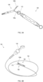
- FIGS. 2A-2B depict a single filament 120 disposed in a linear configuration ( e.g., when stretched) along the length of the traction band 110
- multiple filaments may be disposed along the traction band in a variety of patterns and/or configuration (e.g., zig-zag patterns, knitted patterns, wrapped helically around the traction band, etc.).
- a tissue traction device 100 of the present disclosure may be configured for use with a first endoscopic instrument 130.
- the first endoscopic instrument 130 may include a handle 132 operatively attached to a proximal end of a flexible elongate sheath 134 ( e.g., catheter, etc.) and a first tissue clip 136 releasably attached to a distal end of the flexible elongate sheath 134.
- the instrument 130 may be configured for use with an endoscope, bronchoscope, colonoscope, duodenoscope, ureteroscope, catheters, diagnostic or therapeutic tools or devices, or other types of medical devices.
- the first tissue clip 136 may include first and second arms or jaws 136a, 136b configured to move upon actuation of the handle 132 between a first position (e.g., closed) and a second position (e.g., open). In various embodiments, in the closed position the arms or jaws 136a, 136b of the first tissue clip 136 may engage a target tissue 160 within a body lumen, e.g., a target tissue of the gastrointestinal (GI) tract.
- GI gastrointestinal
- the handle 132 may be further actuated to disengage (e.g., release) the first tissue clip 136 from the distal end of the sheath 134 such that the first tissue clip 136 remains engaged with the target tissue 160 after the first endoscopic instrument 130 has been removed from within the patient.
- a tissue traction system 200 of the present disclosure may include a first endoscopic instrument 130 slidably disposed within a working channel of a flexible elongate tubular member 140 (e.g., endoscope; FIG. 4A-4B ).
- the sheath 134 may extend through the working channel of an endoscope for deploying a clip 136 in a patient.
- the first endoscopic instrument 130 may include a first tissue clip 136 attached to a distal end of a flexible elongate sheath 134.
- a tissue traction device 100 of the present disclosure may be attached to the first tissue clip 136 within the working channel of the flexible elongate member 140.
- a tissue traction system 200 of the present disclosure may be assembled by advancing the first endoscopic instrument 130 through the working channel of the flexible elongate tubular member 140 such that the first tissue clip 136 attached to the distal end of the sheath 134 of the first endoscopic instrument 130 extends distally beyond a distal end of the flexible elongate tubular member 140.
- the handle 132 of the first endoscopic instrument 130 may be actuated to move the first tissue clip 136 from the first position to the second position, e.g. , such that the first and second arms 136a, 136b are open/separated in a Y-shape.
- first or second arms 136a or 136b may then be advanced through an opening of the first attachment member 112 of the tissue traction device 100.
- the handle 132 may then be actuated to move the first tissue clip 136 from the second position to the first position and the first endoscopic instrument 130 may be proximally retracted to load the tissue clip and tissue traction device within the working channel of the elongate tubular member, e.g ., such that the first tissue clip 136 and tissue traction device 100 are disposed ( e.g., protected, shielded, hidden, etc.) within the working channel of the elongate tubular member 140.
- the tissue traction system 200 may then be advanced through a body lumen of a patient and the distal end of the flexible elongate tubular member 140 positioned adjacent to a target tissue 160.
- the first endoscopic instrument 130 may then be distally advanced through the working channel to position the tissue retraction device 100 and first tissue clip 136 attached thereto beyond the distal end of the elongate tubular member 140.
- the handle 132 may then be actuated to move the first tissue clip 136 from the first position to the second position and the open arms 136a, 136b placed in contact with a surface of the target tissue 160 ( e.g., with either one of the first or second arms 136a or 136b extending through an opening of the first attachment member 112 of the tissue traction device 100, as discussed above).
- the handle 132 may then be actuated to move the first tissue clip 136 from the second position to the first position to engage ( e.g., clamp) the first tissue clip 136, and the first attachment member 112 of the tissue traction device 100 attached thereto, with the target tissue 160.
- the first tissue clip 136 may be directly engaged with the portion of the target tissue 160 on which a procedure is to be performed (e.g., tissue to be dissected). Alternatively, the first tissue clip 136 may be engaged with the target tissue 160 adjacent to the portion on which a procedure is to be performed (e.g., the portion being dissected). The handle 132 may then be actuated to disengage the first tissue clip from the sheath 134 of the first endoscopic instrument 130.
- the first endoscopic instrument 130 may then be withdrawn from within the working channel of the flexible elongate tubular member 140 and a second tissue clip 137 attached to the distal end of the sheath 134.
- the first endoscopic instrument 130 may then be advanced back through the working channel to position the second tissue clip 137 beyond the distal end of the flexible elongate tubular member 140.
- the handle 132 of the first endoscopic instrument 130 may then be actuated to move the second tissue clip 137 from the first position to the second position, e.g ., such that the first and second arms 137a, 137b are open/separated in a Y-shape.
- first or second arms 137a or 137b may then be advanced through an opening of the second attachment member 114 of the tissue traction device 100 within the body lumen.
- the first endoscopic instrument 130 may then be distally advanced through the working channel such that the traction band 110 of the tissue traction device 100 engaged with the first or second arms 137a, 137b of the second tissue clip 137 moves ( e.g., stretches) from the first position to an extended/stretched second position.
- the arms 137a, 137b of the second tissue clip 137 may then be placed in contact with a wall of the body lumen opposite the target tissue 160.
- the handle 132 may then be actuated to move the second tissue clip 137 from the second position to the first position to engage ( e.g., clamp) the second tissue clip 137, and the second attachment member 114 of the tissue traction device 100 attached thereto, with the wall of the body lumen opposite the target tissue 160.
- the handle 132 may then be actuated to disengage the second tissue clip 137 from the sheath 134 of the first endoscopic instrument 130, thereby placing the target tissue 160 under tension/traction by the stretched traction band 110 of the tissue traction device 100.
- the traction band 110 may have a maximum second (e.g., stretched) length of approximately 15.00 cm, in various embodiments sufficient traction force may be provided by a traction band having a second length of approximately 8.0 to 9.0 cm.
- the first endoscopic instrument 130 may then be removed (e.g ., withdrawn) from the working channel of the elongate tubular member 140 and a second endoscopic instrument 170 advanced through the working channel to position a second medical device 175 (e.g., an electrocautery knife, resection tool, etc.) attached to a distal end of the second endoscopic instrument adjacent to the target tissue 160.
- a procedure may then be performed on the target tissue 160 (e.g ., the target tissue may then be dissected) using the second medical device 175 while the tissue traction device 100 provides tension/traction on the target tissue 160.
- the tissue traction device 100 may provide tension/traction away from the cutting plane and without impeding/blocking visualization from the distal end of the flexible elongate tubular member 140.
- the direction or angle or amount of traction may be adjusted during the procedure using a third tissue clip 138.
- a third tissue clip 138 may be attached to the distal end of the sheath 134 of the first endoscopic instrument 130 and the first endoscopic instrument advanced through a second working channel of the elongate tubular member 140 to position the third tissue clip 138 beyond the distal end of the elongate tubular member 140.
- the handle 132 of the first endoscopic instrument 130 may then be actuated to move the third tissue clip 138 from the first position to the second position, e.g., such that the first and second arms 138a, 138b are open/separated in a Y-shape.
- the first endoscopic instrument 130 may then be maneuvered to position the stretched traction band (e.g., engaged with the wall of the body lumen by the first and second tissue clips 136, 137) between the first and second arms 138a, 138b of the third tissue clip 138.
- the arms 138a, 138b of the third tissue clip 138 may then be placed in contact with another/second portion of the wall of the body lumen opposite the target tissue 160, drawing a portion of the traction band 110 towards the other/second portion of the wall of the body lumen to apply traction to the target tissue 160.
- the handle 132 may then be actuated to move the third tissue clip 138 from the second position to the first position to engage ( e.g., clamp) the third tissue clip 138 (along with the traction band 110) with the other/second portion of the wall of the body lumen opposite the target tissue 160.
- the handle 132 may then be actuated to disengage the third tissue clip 138 from the sheath 134 of the first endoscopic instrument 130, thereby providing traction to the target tissue in a different direction or plane.
- the direction or angle or amount of traction may be adjusted during the procedure using a third tissue clip and moving the position of the second end of the traction band (opposite the first end which is coupled to the target tissue).
- a first attachment member 212 shown in cross-section with a jaw of a first tissue clip 236 extending therethrough
- the second end of the traction band 210 is extended to couple a second attachment member 214 at the second end of the traction band 210 to another/second portion of the wall of the body lumen opposite the target tissue 160 to apply traction to the target tissue 160.
- more than one second attachment members 214 may be coupled directly or indirectly to the second end of the traction band.
- a traction device 200 is shown with at least two attachment members 214a, 214b, such as in the form of hoops or loops, may be coupled to the second end of the traction band 210.
- each attachment member 214a', 214b' may be coupled to the traction band 210 via a respective stem 215a, 215b. Additional attachment members with or without stems may be provided, and are not shown only for the sake of simplifying the illustrations of the embodiments and not with intent to limit the disclosure.
- a first attachment member 214a, 214a' may be initially coupled to a first anchoring tissue position (similar to as shown in FIG. 4A ). If and when it is desired to modify traction, a third clip is used (such as the third clip 138 described with reference to FIG. 4B ) to engage a different attachment member (such as attachment member 214b, 214b') at the second end of the traction band, such as attachment member 215b, 215b'. The first attachment member at the second end of the traction band may then be cut, either through the loop of the attachment member 214a (such as in the embodiment illustrated in FIG. 5A ) or through the stem element 215a coupling the attachment member 214a' to the traction band 210 (such as in the embodiment illustrated in FIG. 5B ). The third clip and next attachment member may then be engaged with another/second portion of the wall of the body lumen to apply traction to the target tissue 160 from a different direction/angle or with increased tension or otherwise.
- a third clip is used (such as
- the multiple-attachment members coupled to the second end of the traction device are coupled independent of each other, and/or separately coupled to the traction device. As such, each attachment member may function independently of the others. In some embodiments, one or more of the multiple attachment members may be coupled to the traction device via a swivel connection allowing the attachment member to pivot or rotate about or otherwise move with respect to the longitudinal of the traction device.
- an overtube such as, for example, the alignment member described in United States Patent Application Publication US2018/0263614, filed March 19, 2018 , and titled “Tissue Retraction Device and Delivery System", may be provided over at least a portion of the traction band of a traction device formed in accordance with the present disclosure.
- an overtube 380 is provided over the traction band 310 (shown in an extended configuration to apply traction) of a traction device 300.
- the overtube 380 may be provided to facilitate delivery of the traction device 300 through the working channel of the flexible elongate member 140, such as by inhibiting or preventing folding or wrapping of the traction band 310 upon itself (e.g., folding back on itself) while the traction device 300 is advanced and/or manipulated through the working channel.
- the overtube 380 may cover the majority or all of the traction band 310 during advancement of the traction device 310.
- the traction band 310 may extend beyond the end of the overtube 380, as illustrated in FIG. 6 .
- the overtube may be fixed adjacent to the first end of the traction device 300 (e.g., adjacent to the first attachment member 312, to which a first clip 336 may be pre-loaded, or later coupled, to attach the first attachment member to target tissue), such as by crimping (to the traction band or a swivel coupling the attachment member to the traction band or to another end element of the traction device), adhesive, or other connection known to those of ordinary skill in the art.
- Such fixing may be helpful in reliably positioning the overtube, such as if the target tissue is positioned above the endoscope.
- the second tissue clip 137 may be detached from the opposing wall of the body lumen.
- the clips arms may be separated by applying a sufficient amount of force (e.g., using forceps, etc.) to either the jaws and/or a proximal end to disengage the arms of the tissue clip.
- Excised target tissue 160 and attached tissue clips may then be removed from the patient through a working channel of the elongate tubular member 140.
- the traction band 110, 210, 310 or swivels 116, 118 may be cut ( e.g., using the second medical device 175) and the second tissue clip (or second and third tissue clips 137, 138) left behind in the body lumen and expelled from the patient by the body's natural course.
- the second attachment member 114, 214a, 214b, 214a', 214b', 314, or a stem 215a, 215b thereof, can be cut, releasing the traction device 200, 300 therefrom.
- the present disclosure is not limited to a tissue traction device 100, 200, 300 attached to a first tissue clip 136, 236, 336 of a first endoscopic instrument 130 and loaded/pre-loaded within a working channel of an elongate tubular member 140.
- some of steps involved in assembling the tissue retraction device and tissue clip(s) may occur outside of the patient's body, while some other steps involved in assembling the tissue retraction device and tissue clips(s) may occur inside the patient.
- the specific order and/or timing of any or all of these steps is not limited to the description of the present disclosure, but may be performed in a variety of different steps before, during or after a medical procedure.
- a tissue traction device 100, 200, 300 of the present disclosure may be loaded within the flexible elongate sheath 134 of the first endoscopic instrument 130, advanced through the working channel of an elongate tubular member 140 and ejected into the body lumen by distally advancing the first tissue clip 136 , 236, 336 within the sheath 134.
- the first and second attachment members 112, 114, 214a, 214,b, 214a', 214b', 314 of the tissue traction device 100, 200, 300 may then be engaged by respective first and second tissue clips 136, 137, 236, 336 within the body lumen and engaged ( e.g., clamped) to the target tissue and opposing wall of the body lumen as discussed above.
- a tissue traction device 100, 200, 300 of the present disclosure may be pre-loaded within a biopsy cap.
- the pre-loaded biopsy cap may be secured to a proximal end of the elongate tubular member 140 and then distally advanced over/along an outer surface of the elongate tubular member to seal a working channel at a distal end of the elongate tubular member 140.
- the biopsy port and the tissue traction device 100, 200, 300 may then be removed from the biopsy cap within the body lumen using the first tissue clip 136, 236, 336.
- the second medical instrument of the present disclosure is not limited to a tissue resection element (e.g ., electrocautery knife, etc.), but may include a variety of medical instruments configured to manipulate a target tissue under traction (e.g., ablative elements, biopsy needles, injection needles, scissors, graspers, etc.
- a target tissue under traction e.g., ablative elements, biopsy needles, injection needles, scissors, graspers, etc.
- a traction band of the present disclosure is not limited to an elongate (e.g., rectangular) and/or planar (e.g., flat) configuration, but may include a variety of different shapes and/or configurations.
- a traction band of the present disclosure may include a coiled or helical shape; a round, oblong or spherical shape; a square shape; a triangular shape, etc.
- first and second attachment members 112, 114, 212, 214, 312, 314 may be engaged with a variety of different hemostasis (e.g ., Resolution TM Clip, Boston Scientific Corp., Marlborough MA.) and non-hemostasis tissue clips configured to secure/engage the disclosed tissue traction device to the wall of a body lumen.
- a tissue clip contemplated for use with the disclosed tissue traction device may include a naturally open/biased configuration configured to move to a closed/clamped configuration upon actuation by a handle assembly.
- a tissue clip contemplated for use with the disclosed tissue traction device may include a naturally closed/biased configuration configured to move an open configuration upon actuation by a handle assembly.
- fasteners other than the described tissue clips may be used to secure/engage the first and second attachment members of the disclosed tissue traction device to the wall of a body lumen. Examples of fasteners may include, but are not limited to, those described in U.S. Patent Application Publication No. US2018/0263614, filed March 19, 2018 , and titled "Tissue Retraction Device and Delivery System", along with its priority applications U.S. Provisional Patent Application No.
- Patent Application No. 2020/0360006, filed on May 13, 2020 , and titled “Tissue Traction Bands And Methods For Tissue Traction”; and U.S. Patent Application No. 2020/0390446 , filed on May 13, 2020 , and titled “Tether Traction Systems And Methods Of Use Thereof', may complement devices and methods of the present disclosure and may be used therewith.
Landscapes
- Health & Medical Sciences (AREA)
- Life Sciences & Earth Sciences (AREA)
- Surgery (AREA)
- Animal Behavior & Ethology (AREA)
- Public Health (AREA)
- Engineering & Computer Science (AREA)
- Biomedical Technology (AREA)
- Heart & Thoracic Surgery (AREA)
- Medical Informatics (AREA)
- Molecular Biology (AREA)
- Veterinary Medicine (AREA)
- General Health & Medical Sciences (AREA)
- Nuclear Medicine, Radiotherapy & Molecular Imaging (AREA)
- Physics & Mathematics (AREA)
- Biophysics (AREA)
- Optics & Photonics (AREA)
- Pathology (AREA)
- Radiology & Medical Imaging (AREA)
- Ophthalmology & Optometry (AREA)
- Surgical Instruments (AREA)
- Endoscopes (AREA)
Description
- The present disclosure relates generally to the field of medical devices. In particular, the present disclosure relates to tissue traction devices for endoscopic procedures such as tissue dissection.
- A component of accurately and efficiently performing an endoscopic tissue resection/dissection procedure is the ability to maintain traction as the boundaries of the target tissue are dissected. Traction systems that are associated with and/or provided by an endoscopic cap tend to obstruct a physician's view of the target tissue and/or interfere with accessory tools extending alongside or through the endoscope. These complications may directly contribute to increased procedure time, complexity and risk of perforation or bleeding.
- A variety of advantageous medical outcomes may therefore be realized by the tissue retraction devices and related methods of use of the present disclosure.
-
US 2018/035997 A1 relates to a tissue retraction system including a first anchor, a second anchor, and an elongate coupling member extending between the first anchor and the second anchor. The system also may include a holder for receiving the first anchor, the second anchor, and the elongate coupling element. The holder may include a proximal portion and a distal portion. The distal portion may have a smaller width than the proximal portion such that the distal portion exerts a force on a proximal end of the first anchor during deployment of the first anchor from the holder. The force may move the first anchor into an open configuration for receiving tissue. -
US 2007/250116 A1 relates to a method and device for approximation and retraction of tissue portions during a medical procedure. A tissue approximator-retractor elastic device comprises an elastic portion having a contracted length and adapted to expand to a different length to exert a contractile force, and at least three coupling rings spaced along the elastic portion for an operator to choose between the rings and couple at least two rings to at least two tissue portions to adjust a contractile force on the two tissue portions. Also disclosed is providing the device near the tissue portions, coupling a first coupling ring to a first tissue portion, choosing between the remaining coupling rings to select a second coupling ring, engaging the second coupling ring and elastically pulling the elastic portion to the second tissue portion to attach to the second tissue portion. - The invention for which protection is sought is defined by the independent claim. The dependent claims concern particular embodiments.
- In one aspect, the present disclosure relates to a tissue retraction / traction device comprising a traction band comprising a compliant or semi-compliant material. A first attachment member may be pivotably attached to a first end of the traction band by a first swivel. A second attachment member may be pivotably attached to a second end of the traction band by a second swivel.
- In the described and other embodiments, the compliant or semi-compliant material include rubbers, latex, elastics, thermoplastic elastomer (TPE), or combinations thereof. The first and second attachment members may include a compressible material such as polymers, plastics, shape memory metals, shape memory alloys, or combinations thereof. The first and second swivels may pivot around a longitudinal axis of the traction band. The traction band may be configured to move between a first configuration having a length of approximately 2.5 to 4.5 cm and a second configuration having a maximum length of approximately 15.00 cm. A filament is disposed along a length of the traction band. The filament may include a substantially non-compliant material configured to limit a maximum extended length of the traction band or may include a substantially compliant or semi-compliant material configured to increase a retraction force of the traction band.
- In another aspect, the present disclosure relates to a tissue retraction system comprising a flexible elongate tubular member defining a working channel therethrough. A first endoscopic instrument may be disposed within the working channel. The first endoscopic instrument may include a first tissue clip attached to a distal end of the instrument. A tissue retraction device may be disposed within the working channel. A first attachment member of the tissue retraction device may be engaged with the first tissue clip.
- In the described and other embodiments, the first tissue clip may be releasably attachable to the first attachment member of the tissue retraction device. The first tissue clip at a first end of the tissue retraction / traction device may be positionable in a body lumen. A second tissue clip may be positionable in the body lumen and attachable to a second end of the tissue retraction / traction device opposite the first end of the tissue retraction / traction device. A third tissue clip may be positionable in the body lumen and attachable to a portion of the tissue retraction / traction device. The tissue retraction / traction device may include a traction band comprising a compliant or semi-compliant material. A first attachment member may be pivotably attached to a first end of the traction band via a first swivel. A second attachment member may be pivotably attached to a second end of the traction band via a second swivel. The first and second swivels may allow the respective first and second attachment members to pivot around a longitudinal axis of, or otherwise move with respect to, the traction band.
- In various embodiments, more than one attachment member may be provided on the second end of the tissue retraction / traction device. A first tissue clip may be releasably attachable to a first attachment member provided on the first end of the tissue retraction / traction device. The first tissue clip and the first attachment member may be engaged with a target tissue in a body lumen. A second tissue clip may be positionable in the body lumen and attachable to an attachment member provided on the second end of the tissue retraction / traction device. The second tissue clip and accompanying attachment member may be engaged with a first portion of anchoring tissue opposite the target tissue. If it is desired to adjust traction on the tissue retraction / traction device, a third tissue clip may be positionable in the body lumen and attachable to a different attachment member provided on the second end of the tissue retraction / traction device. The third tissue clip and accompanying attachment member may be engaged with a second portion of anchoring tissue opposite the target tissue and spaced apart from the first portion of anchoring tissue. If desired, any attachment member at the second end of the tissue retraction / traction device may be cut to release the clips associated therewith.
- In yet another aspect, the present disclosure relates to an unclaimed method comprising inserting in a body lumen a tissue retraction / traction device loaded onto a first tissue clip of a first endoscopic instrument, advancing the first endoscopic instrument through a working channel of an elongate tubular member and beyond a distal end of the elongate tubular member, and engaging a target tissue of the body lumen with the first tissue clip to secure a first end of the tissue retraction / traction device to a wall of the body lumen.
- In the described and other embodiments, the method may further include releasing the first tissue clip from the first endoscopic instrument. The method may further include withdrawing the first endoscopic instrument from within the working channel of the elongate tubular member and attaching a second tissue clip to the distal end of the first endoscopic instrument. The method may further include advancing the first endoscopic instrument through the working channel of the elongate tubular member and beyond a distal end of the elongate tubular member and engaging the wall of the body lumen with the second tissue clip to secure a second end of the tissue retraction / traction device to the wall of the body lumen. The first and second tissue clips may be engaged with opposite sides of the body lumen. The method may further include releasing the second tissue clip from the first endoscopic instrument. The method may further include manipulating the target tissue with a medical device attached to a distal end of a second endoscopic instrument.
- Non-limiting embodiments of the present disclosure are described by way of example with reference to the accompanying figures, which are schematic and not intended to be drawn to scale. In the figures, each identical or nearly identical component illustrated is typically represented by a single numeral. For purposes of clarity, not every component is labeled in every figure, nor is every component of each embodiment shown where illustration is not necessary to allow those of ordinary skill in the art to understand the disclosure. In the figures:
-
FIG. 1 provides a perspective view of a tissue traction device, according to one embodiment of the present disclosure. -
FIGS. 2A-2B provide perspective views of a tissue traction device, according to one embodiment of the present disclosure. -
FIGS. 3A-3B provide perspective views of a tissue traction system, according to one embodiment of the present disclosure. -
FIGS. 4A-4B provide a schematic illustration of a tissue resection procedure using a tissue traction device, according to one embodiment of the present disclosure. -
FIGS. 5A and 5B provide a perspective view of a tissue traction device according to another embodiment of the present disclosure. -
FIG. 6 provides a perspective view of an embodiment of a tissue traction device illustrating an aspect of the present disclosure. - The present disclosure is not limited to the particular embodiments described herein. The terminology used herein is for the purpose of describing particular embodiments only, and is not intended to be limiting beyond the scope of the appended claims. Unless otherwise defined, all technical terms used herein have the same meaning as commonly understood by one of ordinary skill in the art to which the disclosure belongs.
- Although embodiments of the present disclosure are described with specific reference to tissue retraction / traction devices, systems and methods designed to provide traction within the gastrointestinal tract during a tissue dissection/resection procedure, it should be appreciated that such systems and methods may be used to manipulate a variety of tissues within a variety of different body lumens and/or body passages.
- As used herein, the singular forms "a," "an," and "the" are intended to include the plural forms as well, unless the context clearly indicates otherwise. It will be further understood that the terms "comprises" and/or "comprising," or "includes" and/or "including" when used herein, specify the presence of stated features, regions, steps elements and/or components, but do not preclude the presence or addition of one or more other features, regions, integers, steps, operations, elements, components and/or groups thereof.
- As used herein, the term "distal" refers to the end farthest away from the medical professional when introducing a device into a patient, while the term "proximal" refers to the end closest to the medical professional when introducing a device into a patient.
- In various embodiments, the present disclosure relates generally to devices and systems configured to provide tissue retraction and cutting plane visualization independent of an endoscope during an endoscopic submucosal dissection (ESD) procedure.
- Referring to
FIG. 1 , in one embodiment, a tissue retraction / traction (such terms being used in the alternative, or simply referenced as "traction" for the sake of simplicity and without intent to limit)device 100 of the present disclosure may include a traction band 110 (e.g., elastic band, tether, stretchable elongate member, etc.) formed from or otherwise comprising a variety of compliant or semi-compliant materials. Thetraction band 110 may be an elongate cylindrical tube and may be formed hollow or solid. By way of non-limiting example, such materials may include flexible/stretchable rubbers, thermoplastic elastomer (TPE), plastics, polyethylene terephthalate (PET), and the like. A first attachment member 112 (e.g., loop, hook, ring, mini-snare, etc.) may be pivotably attached to a first end of thetraction band 110 and a second attachment member 114 (e.g., loop, hook, ring, mini-snare, etc.) may be pivotably attached to a second end of thetraction band 110. In various embodiments, the first andsecond attachment members first attachment member 112 may be pivotably attached to the first end of thetraction band 110 by afirst swivel 116 and thesecond attachment member 114 may be pivotably attached to the second end of thetraction band 110 by asecond swivel 118. In various embodiments, the first andsecond attachment members traction band 110. In addition, or alternatively, the first andsecond attachment members traction band 110, an axis parallel to thetraction band 110 and/or any plane or angle of orientation between a perpendicular axis and a longitudinal axis to thetraction band 110. As discussed below, the first andsecond swivels second swivels traction band 110 by an interference fit. For example, a portion of the respective first andsecond swivels traction band 110. In some embodiments, the first andsecond swivels traction band 110. In other embodiments, the first andsecond swivels traction band 110 by an internal coupling component, disposed within and extending along thetraction band 110. - In one embodiment, the
traction band 110 may be configured to move (e.g., stretch) from a first position (e.g., relaxed or non-tensioned) to a second position (e.g., extended, tensioned). By way of non-limiting example, thetraction band 110 may have a length of approximately 2.5 to 4.5 cm when in the first position and may move a second position with maximum length of approximately 15.00 cm. - Referring to
FIGS. 2A-2B , according to the invention, a filament 120 (e.g., wire, connector, band, etc.) is disposed along all or a portion of a length of the traction band 110 (e.g., along a longitudinal axis of the traction band between the first andsecond swivels 116, 118). In various embodiments, thefilament 120 may be attached to an outer surface of thetraction band 110 using a suitable glue, resin, or adhesive. In addition, or alternatively, the filament may be embedded within or integrally formed with the material(s) comprising thetraction band 110. In some embodiments, thefilament 120 may be fixedly coupled to the first and/orsecond swivels - In one embodiment, the
filament 120 may comprise a substantially non-compliant (e.g., rigid or non-stretchable) material configured to limit the maximum length to which thetraction band 110 may stretch. Thefilament 120 may prevent over-stretching of thetraction band 110 beyond a predetermined breaking point. Non-limiting examples of such non-compliant materials may include hard plastics, non-compliant rubber or polymers, metals, and the like. In another embodiment, thefilament 120 may comprise a substantially compliant or semi-compliant material configured to increase (e.g., supplement) the traction force exerted by thetraction band 110 when stretched. - Although
FIGS. 2A-2B depict asingle filament 120 disposed in a linear configuration (e.g., when stretched) along the length of thetraction band 110, in various embodiments, multiple filaments may be disposed along the traction band in a variety of patterns and/or configuration (e.g., zig-zag patterns, knitted patterns, wrapped helically around the traction band, etc.). - Referring to
FIGS. 3A-3B , in one embodiment, atissue traction device 100 of the present disclosure may be configured for use with a firstendoscopic instrument 130. In various embodiments, the firstendoscopic instrument 130 may include ahandle 132 operatively attached to a proximal end of a flexible elongate sheath 134 (e.g., catheter, etc.) and afirst tissue clip 136 releasably attached to a distal end of the flexibleelongate sheath 134. Theinstrument 130 may be configured for use with an endoscope, bronchoscope, colonoscope, duodenoscope, ureteroscope, catheters, diagnostic or therapeutic tools or devices, or other types of medical devices. In one embodiment, thefirst tissue clip 136 may include first and second arms orjaws handle 132 between a first position (e.g., closed) and a second position (e.g., open). In various embodiments, in the closed position the arms orjaws first tissue clip 136 may engage atarget tissue 160 within a body lumen, e.g., a target tissue of the gastrointestinal (GI) tract. In various additional embodiments, thehandle 132 may be further actuated to disengage (e.g., release) thefirst tissue clip 136 from the distal end of thesheath 134 such that thefirst tissue clip 136 remains engaged with thetarget tissue 160 after the firstendoscopic instrument 130 has been removed from within the patient. - In one embodiment, a
tissue traction system 200 of the present disclosure may include a firstendoscopic instrument 130 slidably disposed within a working channel of a flexible elongate tubular member 140 (e.g., endoscope;FIG. 4A-4B ). For example, thesheath 134 may extend through the working channel of an endoscope for deploying aclip 136 in a patient. As discussed above, the firstendoscopic instrument 130 may include afirst tissue clip 136 attached to a distal end of a flexibleelongate sheath 134. In one embodiment, atissue traction device 100 of the present disclosure may be attached to thefirst tissue clip 136 within the working channel of the flexibleelongate member 140. For example, atissue traction system 200 of the present disclosure may be assembled by advancing the firstendoscopic instrument 130 through the working channel of the flexible elongatetubular member 140 such that thefirst tissue clip 136 attached to the distal end of thesheath 134 of the firstendoscopic instrument 130 extends distally beyond a distal end of the flexible elongatetubular member 140. Thehandle 132 of the firstendoscopic instrument 130 may be actuated to move thefirst tissue clip 136 from the first position to the second position, e.g., such that the first andsecond arms second arms first attachment member 112 of thetissue traction device 100. Thehandle 132 may then be actuated to move thefirst tissue clip 136 from the second position to the first position and the firstendoscopic instrument 130 may be proximally retracted to load the tissue clip and tissue traction device within the working channel of the elongate tubular member, e.g., such that thefirst tissue clip 136 andtissue traction device 100 are disposed (e.g., protected, shielded, hidden, etc.) within the working channel of the elongatetubular member 140. - Referring to
FIG. 4A , thetissue traction system 200 may then be advanced through a body lumen of a patient and the distal end of the flexible elongatetubular member 140 positioned adjacent to atarget tissue 160. The firstendoscopic instrument 130 may then be distally advanced through the working channel to position thetissue retraction device 100 andfirst tissue clip 136 attached thereto beyond the distal end of the elongatetubular member 140. Thehandle 132 may then be actuated to move thefirst tissue clip 136 from the first position to the second position and theopen arms second arms first attachment member 112 of thetissue traction device 100, as discussed above). Thehandle 132 may then be actuated to move thefirst tissue clip 136 from the second position to the first position to engage (e.g., clamp) thefirst tissue clip 136, and thefirst attachment member 112 of thetissue traction device 100 attached thereto, with thetarget tissue 160. In one embodiment, thefirst tissue clip 136 may be directly engaged with the portion of thetarget tissue 160 on which a procedure is to be performed (e.g., tissue to be dissected). Alternatively, thefirst tissue clip 136 may be engaged with thetarget tissue 160 adjacent to the portion on which a procedure is to be performed (e.g., the portion being dissected). Thehandle 132 may then be actuated to disengage the first tissue clip from thesheath 134 of the firstendoscopic instrument 130. - In one embodiment, the first
endoscopic instrument 130 may then be withdrawn from within the working channel of the flexible elongatetubular member 140 and asecond tissue clip 137 attached to the distal end of thesheath 134. The firstendoscopic instrument 130 may then be advanced back through the working channel to position thesecond tissue clip 137 beyond the distal end of the flexible elongatetubular member 140. Thehandle 132 of the firstendoscopic instrument 130 may then be actuated to move thesecond tissue clip 137 from the first position to the second position, e.g., such that the first andsecond arms second arms second attachment member 114 of thetissue traction device 100 within the body lumen. The firstendoscopic instrument 130 may then be distally advanced through the working channel such that thetraction band 110 of thetissue traction device 100 engaged with the first orsecond arms second tissue clip 137 moves (e.g., stretches) from the first position to an extended/stretched second position. Thearms second tissue clip 137 may then be placed in contact with a wall of the body lumen opposite thetarget tissue 160. Thehandle 132 may then be actuated to move thesecond tissue clip 137 from the second position to the first position to engage (e.g., clamp) thesecond tissue clip 137, and thesecond attachment member 114 of thetissue traction device 100 attached thereto, with the wall of the body lumen opposite thetarget tissue 160. Thehandle 132 may then be actuated to disengage thesecond tissue clip 137 from thesheath 134 of the firstendoscopic instrument 130, thereby placing thetarget tissue 160 under tension/traction by the stretchedtraction band 110 of thetissue traction device 100. Although thetraction band 110 may have a maximum second (e.g., stretched) length of approximately 15.00 cm, in various embodiments sufficient traction force may be provided by a traction band having a second length of approximately 8.0 to 9.0 cm. - In various embodiments, the first
endoscopic instrument 130 may then be removed (e.g., withdrawn) from the working channel of the elongatetubular member 140 and a second endoscopic instrument 170 advanced through the working channel to position a second medical device 175 (e.g., an electrocautery knife, resection tool, etc.) attached to a distal end of the second endoscopic instrument adjacent to thetarget tissue 160. A procedure may then be performed on the target tissue 160 (e.g., the target tissue may then be dissected) using the second medical device 175 while thetissue traction device 100 provides tension/traction on thetarget tissue 160. For instance, thetissue traction device 100 may provide tension/traction away from the cutting plane and without impeding/blocking visualization from the distal end of the flexible elongatetubular member 140. - Referring to
FIG. 4B , in one embodiment, the direction or angle or amount of traction may be adjusted during the procedure using athird tissue clip 138. For example, athird tissue clip 138 may be attached to the distal end of thesheath 134 of the firstendoscopic instrument 130 and the first endoscopic instrument advanced through a second working channel of the elongatetubular member 140 to position thethird tissue clip 138 beyond the distal end of the elongatetubular member 140. Thehandle 132 of the firstendoscopic instrument 130 may then be actuated to move thethird tissue clip 138 from the first position to the second position, e.g., such that the first and second arms 138a, 138b are open/separated in a Y-shape. The firstendoscopic instrument 130 may then be maneuvered to position the stretched traction band (e.g., engaged with the wall of the body lumen by the first and second tissue clips 136, 137) between the first and second arms 138a, 138b of thethird tissue clip 138. The arms 138a, 138b of thethird tissue clip 138 may then be placed in contact with another/second portion of the wall of the body lumen opposite thetarget tissue 160, drawing a portion of thetraction band 110 towards the other/second portion of the wall of the body lumen to apply traction to thetarget tissue 160. Thehandle 132 may then be actuated to move thethird tissue clip 138 from the second position to the first position to engage (e.g., clamp) the third tissue clip 138 (along with the traction band 110) with the other/second portion of the wall of the body lumen opposite thetarget tissue 160. Thehandle 132 may then be actuated to disengage thethird tissue clip 138 from thesheath 134 of the firstendoscopic instrument 130, thereby providing traction to the target tissue in a different direction or plane. - Referring to
FIGS. 5A and 5B , in another embodiment, the direction or angle or amount of traction may be adjusted during the procedure using a third tissue clip and moving the position of the second end of the traction band (opposite the first end which is coupled to the target tissue). In various embodiments, once a first attachment member 212 (shown in cross-section with a jaw of afirst tissue clip 236 extending therethrough) is coupled to targettissue 160, such as via afirst tissue clip 236, the second end of thetraction band 210 is extended to couple asecond attachment member 214 at the second end of thetraction band 210 to another/second portion of the wall of the body lumen opposite thetarget tissue 160 to apply traction to thetarget tissue 160. As illustrated inFIGS. 5A and 5B , more than onesecond attachment members 214 may be coupled directly or indirectly to the second end of the traction band. Referring toFIG. 5A , atraction device 200 is shown with at least twoattachment members traction band 210. Referring toFIG. 5B , eachattachment member 214a', 214b' may be coupled to thetraction band 210 via arespective stem first attachment member FIG. 4A ). If and when it is desired to modify traction, a third clip is used (such as thethird clip 138 described with reference toFIG. 4B ) to engage a different attachment member (such asattachment member attachment member attachment member 214a (such as in the embodiment illustrated inFIG. 5A ) or through thestem element 215a coupling theattachment member 214a' to the traction band 210 (such as in the embodiment illustrated inFIG. 5B ). The third clip and next attachment member may then be engaged with another/second portion of the wall of the body lumen to apply traction to thetarget tissue 160 from a different direction/angle or with increased tension or otherwise. - In various embodiments, the multiple-attachment members coupled to the second end of the traction device are coupled independent of each other, and/or separately coupled to the traction device. As such, each attachment member may function independently of the others. In some embodiments, one or more of the multiple attachment members may be coupled to the traction device via a swivel connection allowing the attachment member to pivot or rotate about or otherwise move with respect to the longitudinal of the traction device.
- In various embodiments, an overtube, such as, for example, the alignment member described in United States Patent Application Publication
US2018/0263614, filed March 19, 2018 , and titled "Tissue Retraction Device and Delivery System", may be provided over at least a portion of the traction band of a traction device formed in accordance with the present disclosure. Referring toFIG. 6 , anovertube 380 is provided over the traction band 310 (shown in an extended configuration to apply traction) of atraction device 300. Theovertube 380 may be provided to facilitate delivery of thetraction device 300 through the working channel of the flexibleelongate member 140, such as by inhibiting or preventing folding or wrapping of thetraction band 310 upon itself (e.g., folding back on itself) while thetraction device 300 is advanced and/or manipulated through the working channel. Theovertube 380 may cover the majority or all of thetraction band 310 during advancement of thetraction device 310. However, once the first attachment member 312 (shown in cross-section with a jaw of afirst tissue clip 336 extending therethrough) is coupled to targettissue 160, such as via afirst tissue clip 336, and the second end of thetraction band 310 is extended to couple thesecond attachment member 314 to another/second portion of the wall of the body lumen opposite thetarget tissue 160 to apply traction to thetarget tissue 160, thetraction band 310 may extend beyond the end of theovertube 380, as illustrated inFIG. 6 . In various embodiments, the overtube may be fixed adjacent to the first end of the traction device 300 (e.g., adjacent to thefirst attachment member 312, to which afirst clip 336 may be pre-loaded, or later coupled, to attach the first attachment member to target tissue), such as by crimping (to the traction band or a swivel coupling the attachment member to the traction band or to another end element of the traction device), adhesive, or other connection known to those of ordinary skill in the art. Such fixing may be helpful in reliably positioning the overtube, such as if the target tissue is positioned above the endoscope. - In various embodiments, with the
first tissue clip target tissue 160 on which a procedure is to be performed (e.g., tissue being dissected), after the procedure has been completed (e.g., the target tissue has been fully dissected), the second tissue clip 137 (or second and third tissue clips 137, 138) may be detached from the opposing wall of the body lumen. In some embodiments, the clips arms may be separated by applying a sufficient amount of force (e.g., using forceps, etc.) to either the jaws and/or a proximal end to disengage the arms of the tissue clip.Excised target tissue 160 and attached tissue clips may then be removed from the patient through a working channel of the elongatetubular member 140. Alternatively, thetraction band second attachment member stem traction device - The present disclosure is not limited to a
tissue traction device first tissue clip endoscopic instrument 130 and loaded/pre-loaded within a working channel of an elongatetubular member 140. In various embodiments, some of steps involved in assembling the tissue retraction device and tissue clip(s) may occur outside of the patient's body, while some other steps involved in assembling the tissue retraction device and tissue clips(s) may occur inside the patient. The specific order and/or timing of any or all of these steps is not limited to the description of the present disclosure, but may be performed in a variety of different steps before, during or after a medical procedure. For example, in one embodiment, atissue traction device elongate sheath 134 of the firstendoscopic instrument 130, advanced through the working channel of an elongatetubular member 140 and ejected into the body lumen by distally advancing thefirst tissue clip sheath 134. The first andsecond attachment members tissue traction device tissue traction device tubular member 140 and then distally advanced over/along an outer surface of the elongate tubular member to seal a working channel at a distal end of the elongatetubular member 140. The biopsy port and thetissue traction device first tissue clip - In various embodiments, the second medical instrument of the present disclosure is not limited to a tissue resection element (e.g., electrocautery knife, etc.), but may include a variety of medical instruments configured to manipulate a target tissue under traction (e.g., ablative elements, biopsy needles, injection needles, scissors, graspers, etc.
- In various additional embodiments, a traction band of the present disclosure is not limited to an elongate (e.g., rectangular) and/or planar (e.g., flat) configuration, but may include a variety of different shapes and/or configurations. For example, a traction band of the present disclosure may include a coiled or helical shape; a round, oblong or spherical shape; a square shape; a triangular shape, etc.
- In various additional embodiments, the first and
second attachment members US2018/0263614, filed March 19, 2018 , and titled "Tissue Retraction Device and Delivery System", along with its priority applicationsU.S. Provisional Patent Application No. 62/506,780 filed May 16, 2017 U.S. Provisional Application No. 62/473,957, filed March 20, 2017 U.S. Patent Application No. 15/925,110, filed March 19, 2018 U.S. Patent Application Publication No. 2020/0129181, filed October 30, 2019 , and titled "Clip Devices, Systems, and Methods for Engaging Tissue"; andU.S. Patent No. 8,062,311, issued November 22, 2011 , and titled "Endoscopic Hemostatic Clipping Apparatus". Other features and aspects of these patents and patent applications, as well asU.S. Patent Application No. 2020/0360006, filed on May 13, 2020 , and titled "Tissue Traction Bands And Methods For Tissue Traction"; andU.S. Patent Application No. 2020/0390446 , filed on May 13, 2020 , and titled "Tether Traction Systems And Methods Of Use Thereof', may complement devices and methods of the present disclosure and may be used therewith. - All of the devices disclosed and claimed herein can be made and executed without undue experimentation in light of the present disclosure. While the devices and methods of this disclosure have been described in terms of preferred embodiments, it may be apparent to those of skill in the art that variations can be applied to the devices and/or methods and in the steps or in the sequence of steps of the method described herein without departing from the concept and scope of the disclosure. All such similar substitutes and modifications apparent to those skilled in the art are deemed to be within the scope and concept of the disclosure as defined by the appended claims.
Claims (9)
- A tissue traction device (100, 300), comprising:a traction band (110, 210, 310) comprising a compliant or semi-compliant material;a first attachment member (112, 212, 312) pivotably attached to a first end of the traction band (110, 210, 310) by a first swivel (116); anda second attachment member (114, 214, 314) pivotably attached to a second end of the traction band (110, 210, 310) by a second swivel (118), anda filament (120) disposed along a length of the traction band (110, 210, 310),wherein the filament (120) comprises a substantially non-compliant material configured to limit a maximum extended length of the traction band (110, 210, 310), or wherein the filament (120) comprises a substantially compliant or semi-compliant material configured to increase a retraction force of the traction band (110, 210, 310).
- The tissue traction device of claim 1, wherein the compliant or semi-compliant material is selected from the group consisting of rubbers, latex, elastics and TPE, or combinations thereof.
- The tissue traction device of any of claims 1 or 2, wherein the first and second attachment members (112, 212, 312, 114, 214, 314) comprise a compressible material selected from the group consisting of polymers, plastics, shape memory metals, shape memory alloys, or combinations thereof.
- The tissue traction device of any of claims 1-3, wherein the first and second attachment members (112, 212, 312, 114, 214, 314) pivot around a longitudinal axis of the traction band (110, 210, 310) via the first and second swivels (116, 118), respectively.
- The tissue traction device of any of claims 1-4, wherein the traction band (110, 210, 310) is configured to move from between a configuration having a length of approximately 2.5 to 4.5 cm and a second configuration having a maximum length of approximately 15.00 cm.
- A tissue traction system (200), comprising:a flexible elongate tubular member (140) defining a working channel therethrough;a first endoscopic instrument (130) disposed within the working channel, wherein the first endoscopic instrument (130) includes a first tissue clip (136, 236, 336) attached to a distal end of the instrument; anda tissue traction device (100, 300) of any of claims 1-5, disposed within the working channel, wherein the first attachment member (112, 212, 312) of the tissue traction device (100, 300) is engaged with the first tissue clip (136, 236, 336).
- The tissue traction system of claim 6, wherein the first tissue clip (136, 236, 336) is releasably attachable to the first attachment member (112, 212, 312) of the tissue traction device (100, 300).
- The tissue retraction system of any of claims 6-7, wherein the first tissue clip (136, 236, 336) at a first end of the tissue traction device (100, 300) is positionable in a body lumen, and wherein a second tissue clip (137) is positionable in the body lumen and attachable to a second end opposite of the first end of the tissue traction device (100, 300).
- The tissue retraction system of any of claims 6-8, wherein a third tissue clip (138) is positionable in the body lumen and attachable to a portion of the tissue traction device (100, 300).
Priority Applications (1)
| Application Number | Priority Date | Filing Date | Title |
|---|---|---|---|
| EP24203645.7A EP4473915A3 (en) | 2019-05-16 | 2020-05-13 | Tissue traction bands |
Applications Claiming Priority (3)
| Application Number | Priority Date | Filing Date | Title |
|---|---|---|---|
| US201962848815P | 2019-05-16 | 2019-05-16 | |
| US201962908972P | 2019-10-01 | 2019-10-01 | |
| PCT/US2020/032581 WO2020232057A1 (en) | 2019-05-16 | 2020-05-13 | Tissue traction bands |
Related Child Applications (1)
| Application Number | Title | Priority Date | Filing Date |
|---|---|---|---|
| EP24203645.7A Division EP4473915A3 (en) | 2019-05-16 | 2020-05-13 | Tissue traction bands |
Publications (2)
| Publication Number | Publication Date |
|---|---|
| EP3923824A1 EP3923824A1 (en) | 2021-12-22 |
| EP3923824B1 true EP3923824B1 (en) | 2024-10-16 |
Family
ID=70919198
Family Applications (3)
| Application Number | Title | Priority Date | Filing Date |
|---|---|---|---|
| EP24203645.7A Pending EP4473915A3 (en) | 2019-05-16 | 2020-05-13 | Tissue traction bands |
| EP20729508.0A Active EP3923824B1 (en) | 2019-05-16 | 2020-05-13 | Tissue traction bands |
| EP20729509.8A Pending EP3968866A1 (en) | 2019-05-16 | 2020-05-13 | Tissue traction bands and methods for tissue traction |
Family Applications Before (1)
| Application Number | Title | Priority Date | Filing Date |
|---|---|---|---|
| EP24203645.7A Pending EP4473915A3 (en) | 2019-05-16 | 2020-05-13 | Tissue traction bands |
Family Applications After (1)
| Application Number | Title | Priority Date | Filing Date |
|---|---|---|---|
| EP20729509.8A Pending EP3968866A1 (en) | 2019-05-16 | 2020-05-13 | Tissue traction bands and methods for tissue traction |
Country Status (5)
| Country | Link |
|---|---|
| US (6) | US10952717B2 (en) |
| EP (3) | EP4473915A3 (en) |
| JP (4) | JP7234407B2 (en) |
| CN (3) | CN119606453A (en) |
| WO (2) | WO2020232057A1 (en) |
Families Citing this family (10)
| Publication number | Priority date | Publication date | Assignee | Title |
|---|---|---|---|---|
| CN110731802A (en) * | 2018-07-20 | 2020-01-31 | 南微医学科技股份有限公司 | traction device |
| CN119606453A (en) * | 2019-05-16 | 2025-03-14 | 波士顿科学国际有限公司 | Tissue traction belt and method of tissue traction |
| EP4736735A2 (en) | 2019-06-14 | 2026-05-06 | Boston Scientific Scimed, Inc. | Tether traction systems and methods of use thereof |
| CN114980818B (en) * | 2019-12-05 | 2025-12-02 | 波士顿科学国际有限公司 | Traction devices, systems and methods |
| US12268380B2 (en) | 2020-12-22 | 2025-04-08 | Boston Scientific Medical Device Limited | Scaffold devices, systems, and methods for tissue traction |
| CN118678922A (en) * | 2022-02-09 | 2024-09-20 | 波士顿科学国际有限公司 | Devices, systems, and methods for tissue distraction |
| JPWO2024024931A1 (en) * | 2022-07-29 | 2024-02-01 | ||
| US11850356B1 (en) | 2023-06-08 | 2023-12-26 | Microneb Tech Holdings, Inc. | Apparatus, methods, and systems for administering a medication to a patient from a capsule using an atomizer |
| US12096922B1 (en) | 2023-10-25 | 2024-09-24 | Krueze Innovations LLC | Apparatus, methods, and systems for improving surgical control with a medical torquing device |
| WO2025147611A1 (en) * | 2024-01-05 | 2025-07-10 | Boston Scientific Medical Device Limited | Devices, systems, and methods for tissue traction |
Family Cites Families (52)
| Publication number | Priority date | Publication date | Assignee | Title |
|---|---|---|---|---|
| US5366459A (en) * | 1987-05-14 | 1994-11-22 | Inbae Yoon | Surgical clip and clip application procedures |
| US5749879A (en) * | 1989-08-16 | 1998-05-12 | Medtronic, Inc. | Device or apparatus for manipulating matter |
| US5379759A (en) * | 1991-02-04 | 1995-01-10 | Sewell, Jr.; Frank K. | Retractor for endoscopic surgery |
| US5582577A (en) * | 1995-02-13 | 1996-12-10 | Vance Products Incorporated | Surgical retractor including central elastic member |
| US5803903A (en) * | 1997-08-15 | 1998-09-08 | Mist, Inc. | Surgical retractor and method of use with balloon dissection |
| US6090043A (en) * | 1999-05-17 | 2000-07-18 | Applied Medical Technology, Inc. | Tissue retractor retention band |
| US7022069B1 (en) * | 2001-07-30 | 2006-04-04 | Si-1, Inc. | Circumferential retractor apparatus with locking slots |
| US7101395B2 (en) * | 2002-06-12 | 2006-09-05 | Mitral Interventions, Inc. | Method and apparatus for tissue connection |
| JP4147315B2 (en) * | 2002-09-13 | 2008-09-10 | Hoya株式会社 | Magnetic anchor remote guidance system |
| JP4320205B2 (en) * | 2003-04-22 | 2009-08-26 | Hoya株式会社 | Endoscope guidance means guidance system and endoscope guidance device |
| JP2005103107A (en) | 2003-09-30 | 2005-04-21 | Shinshu Tlo:Kk | Medical gripping tool and mounting method for mounting the medical gripping tool in the body |
| EP1684641B1 (en) | 2003-11-07 | 2012-02-15 | Scimed Life Systems, Inc. | Endoscopic hemoscopic clipping apparatus |
| US20050250988A1 (en) * | 2004-05-07 | 2005-11-10 | Usgi Medical Inc. | Removable apparatus for manipulating and securing tissue within a treatment space |
| JP4746348B2 (en) | 2004-05-20 | 2011-08-10 | パンカジュ・ジャイ・パスリチャ | Therapeutic treatment device |
| JP4484153B2 (en) * | 2005-09-02 | 2010-06-16 | Hoya株式会社 | Endoscope gripping device |
| US8758375B2 (en) * | 2005-09-28 | 2014-06-24 | Olympus Medical Systems Corp | Method for suturing perforation |
| US20070250116A1 (en) * | 2006-04-25 | 2007-10-25 | Board Of Regents, The University Of Texas System | Tissue Approximator and Retractor Assistive Device |
| JP4472680B2 (en) | 2006-09-09 | 2010-06-02 | 太一 坂本 | Medical gripper and medical clip |
| US8114018B2 (en) * | 2006-10-10 | 2012-02-14 | Park Adrian E | Adjustable line and net retractors |
| JP5192771B2 (en) * | 2006-11-28 | 2013-05-08 | 信行 櫻澤 | Mucosal traction tool |
| EP2282664A4 (en) * | 2008-06-03 | 2013-07-31 | Virtual Ports Ltd | MULTI-COMPONENT DEVICE, SYSTEM AND METHOD FOR FACILITATING MINIMAL EFFRACTION PROCEDURES |
| US8251889B2 (en) * | 2009-02-25 | 2012-08-28 | Mis Solutions, Inc. | Apparatus and method for intra-abdominally moving a first internal organ to a position away from a second internal organ and then holding the first internal organ in the position without manual input |
| US8403837B2 (en) * | 2009-08-13 | 2013-03-26 | Covidien Lp | Deployable jaws retraction device |
| US8551078B2 (en) * | 2009-12-04 | 2013-10-08 | Covidien Lp | Laparoscopic scaffold assembly |
| WO2018156768A1 (en) | 2017-02-22 | 2018-08-30 | Cornell University | Method and apparatus for providing increased visualization and manipulation of a body side wall |
| WO2012004787A1 (en) * | 2010-07-05 | 2012-01-12 | Virtual Ports Ltd. | An internal retractor |
| US9072517B2 (en) * | 2010-11-15 | 2015-07-07 | Wake Forest University Health Sciences | Natural orifice transluminal endoscopic devices for closure of luminal perforations and associated methods |
| US8979746B2 (en) * | 2011-06-13 | 2015-03-17 | Jae-Hwang Kim | Retraction device for laparoscopy |
| EP2750613B1 (en) * | 2011-08-25 | 2017-11-01 | FreeHold Surgical, Inc. | Apparatus for intra-abdominally moving a first internal organ to a position away from a second internal organ and then holding the first internal organ in the position without manual input |
| CN104114105B (en) * | 2011-09-23 | 2017-06-30 | 外科透视有限公司 | The folder that organ is retracted is carried out during for Minimally Invasive Surgery |
| CA2877865C (en) * | 2012-06-29 | 2020-09-01 | Jeffrey Smith | Apparatus and method for delivering surgical tissue connectors into an abdominal cavity and removing the surgical tissue connectors from the abdominal cavity |
| KR101293282B1 (en) * | 2013-01-11 | 2013-08-09 | 아주대학교산학협력단 | Surgical retractor |
| ES2703574T3 (en) * | 2014-06-20 | 2019-03-11 | Endo Tools Therapeutics S A | Set to fix gastrointestinal tissue folds |
| CN204839606U (en) | 2015-06-25 | 2015-12-09 | 周征兵 | Multi -functional skin elasticity drag hook |
| US10973506B2 (en) * | 2016-08-05 | 2021-04-13 | Boston Scientific Scimed, Inc. | Systems, devices, and related methods for retracting tissue |
| CN109788949B (en) * | 2016-09-30 | 2021-11-30 | 波士顿科学国际有限公司 | Tissue retraction device |
| US10543073B2 (en) * | 2016-11-02 | 2020-01-28 | Tas Medical Inc. | System and methods for closing a fascial opening |
| CN207152620U (en) * | 2017-01-17 | 2018-03-30 | 南通市中医院 | A kind of anal fistula dragging line |
| US10524771B2 (en) * | 2017-03-15 | 2020-01-07 | Baxter International Inc. | Organ retraction device |
| EP3544522B1 (en) * | 2017-03-20 | 2021-09-01 | Boston Scientific Scimed, Inc. | Tissue retraction device and delivery system |
| EP3554334A2 (en) * | 2017-03-29 | 2019-10-23 | Boston Scientific Scimed, Inc. | Devices and methods for tissue retraction |
| KR102870215B1 (en) * | 2017-10-02 | 2025-10-14 | 보스톤 싸이엔티픽 싸이메드 인코포레이티드 | Devices and methods for tissue retraction |
| CN111343929B (en) * | 2017-11-08 | 2024-03-19 | 梅奥医学教育及研究基金会 | Systems and methods for endoscopic submucosal dissection using magnetically attachable vascular clips |
| US11350946B2 (en) * | 2017-11-08 | 2022-06-07 | Mayo Foundation For Medical Education And Research | Systems and methods for endoscopic submucosal dissection using magnetically attachable clips |
| CN107928721A (en) * | 2017-11-24 | 2018-04-20 | 杭州市第人民医院 | Abdominal operation hangs liver device |
| CN110731802A (en) | 2018-07-20 | 2020-01-31 | 南微医学科技股份有限公司 | traction device |
| CN209611212U (en) | 2018-07-20 | 2019-11-12 | 南京微创医学科技股份有限公司 | A traction device and a traction ring for the traction device |
| EP4473917A3 (en) | 2018-10-31 | 2025-02-12 | Boston Scientific Scimed, Inc. | Clip device for engaging tissue |
| CN109350147A (en) * | 2018-12-21 | 2019-02-19 | 遵义医学院附属医院 | A kind of laparoscopic surgery retractor hook |
| US11147564B2 (en) | 2019-05-14 | 2021-10-19 | Boston Scientific Scimed, Inc. | Tissue clip devices, systems, and traction methods |
| CN119606453A (en) | 2019-05-16 | 2025-03-14 | 波士顿科学国际有限公司 | Tissue traction belt and method of tissue traction |
| EP4736735A2 (en) | 2019-06-14 | 2026-05-06 | Boston Scientific Scimed, Inc. | Tether traction systems and methods of use thereof |
-
2020
- 2020-05-13 CN CN202510009305.7A patent/CN119606453A/en active Pending
- 2020-05-13 EP EP24203645.7A patent/EP4473915A3/en active Pending
- 2020-05-13 WO PCT/US2020/032581 patent/WO2020232057A1/en not_active Ceased
- 2020-05-13 US US15/930,613 patent/US10952717B2/en active Active
- 2020-05-13 EP EP20729508.0A patent/EP3923824B1/en active Active
- 2020-05-13 EP EP20729509.8A patent/EP3968866A1/en active Pending
- 2020-05-13 CN CN202080035361.3A patent/CN113853166A/en active Pending
- 2020-05-13 US US15/930,620 patent/US11980355B2/en active Active
- 2020-05-13 WO PCT/US2020/032583 patent/WO2020232059A1/en not_active Ceased
- 2020-05-13 CN CN202080051421.0A patent/CN114364328B/en active Active
- 2020-05-13 JP JP2021557103A patent/JP7234407B2/en active Active
-
2021
- 2021-02-12 US US17/174,952 patent/US11890001B2/en active Active
-
2023
- 2023-02-22 JP JP2023025705A patent/JP7543463B2/en active Active
- 2023-12-19 US US18/545,167 patent/US12290255B2/en active Active
-
2024
- 2024-04-09 US US18/630,543 patent/US20240252160A1/en active Pending
- 2024-08-21 JP JP2024139441A patent/JP7757481B2/en active Active
-
2025
- 2025-04-04 US US19/170,773 patent/US20250228545A1/en active Pending
- 2025-10-08 JP JP2025169828A patent/JP2025182113A/en active Pending
Also Published As
| Publication number | Publication date |
|---|---|
| US20200360006A1 (en) | 2020-11-19 |
| EP4473915A2 (en) | 2024-12-11 |
| US11980355B2 (en) | 2024-05-14 |
| JP2024152891A (en) | 2024-10-25 |
| JP7543463B2 (en) | 2024-09-02 |
| US20240115251A1 (en) | 2024-04-11 |
| US20240252160A1 (en) | 2024-08-01 |
| CN114364328B (en) | 2025-01-14 |
| CN119606453A (en) | 2025-03-14 |
| US10952717B2 (en) | 2021-03-23 |
| CN114364328A (en) | 2022-04-15 |
| WO2020232057A1 (en) | 2020-11-19 |
| JP2022525979A (en) | 2022-05-20 |
| JP7234407B2 (en) | 2023-03-07 |
| JP2025182113A (en) | 2025-12-11 |
| US20210186480A1 (en) | 2021-06-24 |
| JP2023059943A (en) | 2023-04-27 |
| WO2020232059A1 (en) | 2020-11-19 |
| CN113853166A (en) | 2021-12-28 |
| EP3923824A1 (en) | 2021-12-22 |
| JP7757481B2 (en) | 2025-10-21 |
| US12290255B2 (en) | 2025-05-06 |
| US11890001B2 (en) | 2024-02-06 |
| EP3968866A1 (en) | 2022-03-23 |
| EP4473915A3 (en) | 2025-02-19 |
| US20250228545A1 (en) | 2025-07-17 |
| US20200360005A1 (en) | 2020-11-19 |
Similar Documents
| Publication | Publication Date | Title |
|---|---|---|
| US12290255B2 (en) | Tissue retraction bands and methods of use thereof | |
| JP7536961B2 (en) | Traction system for endoscopic procedures and method of use thereof | |
| AU2020398163B2 (en) | Tissue traction devices, systems, and methods |
Legal Events
| Date | Code | Title | Description |
|---|---|---|---|
| STAA | Information on the status of an ep patent application or granted ep patent |
Free format text: STATUS: UNKNOWN |
|
| STAA | Information on the status of an ep patent application or granted ep patent |
Free format text: STATUS: THE INTERNATIONAL PUBLICATION HAS BEEN MADE |
|
| PUAI | Public reference made under article 153(3) epc to a published international application that has entered the european phase |
Free format text: ORIGINAL CODE: 0009012 |
|
| STAA | Information on the status of an ep patent application or granted ep patent |
Free format text: STATUS: REQUEST FOR EXAMINATION WAS MADE |
|
| 17P | Request for examination filed |
Effective date: 20210913 |
|
| AK | Designated contracting states |
Kind code of ref document: A1 Designated state(s): AL AT BE BG CH CY CZ DE DK EE ES FI FR GB GR HR HU IE IS IT LI LT LU LV MC MK MT NL NO PL PT RO RS SE SI SK SM TR |
|
| DAV | Request for validation of the european patent (deleted) | ||
| DAX | Request for extension of the european patent (deleted) | ||
| GRAP | Despatch of communication of intention to grant a patent |
Free format text: ORIGINAL CODE: EPIDOSNIGR1 |
|
| STAA | Information on the status of an ep patent application or granted ep patent |
Free format text: STATUS: GRANT OF PATENT IS INTENDED |
|
| INTG | Intention to grant announced |
Effective date: 20240516 |
|
| GRAS | Grant fee paid |
Free format text: ORIGINAL CODE: EPIDOSNIGR3 |
|
| GRAA | (expected) grant |
Free format text: ORIGINAL CODE: 0009210 |
|
| STAA | Information on the status of an ep patent application or granted ep patent |
Free format text: STATUS: THE PATENT HAS BEEN GRANTED |
|
| AK | Designated contracting states |
Kind code of ref document: B1 Designated state(s): AL AT BE BG CH CY CZ DE DK EE ES FI FR GB GR HR HU IE IS IT LI LT LU LV MC MK MT NL NO PL PT RO RS SE SI SK SM TR |
|
| REG | Reference to a national code |
Ref country code: GB Ref legal event code: FG4D |
|
| REG | Reference to a national code |
Ref country code: CH Ref legal event code: EP Ref country code: DE Ref legal event code: R096 Ref document number: 602020039545 Country of ref document: DE |
|
| REG | Reference to a national code |
Ref country code: IE Ref legal event code: FG4D |
|
| REG | Reference to a national code |
Ref country code: NL Ref legal event code: FP |
|
| REG | Reference to a national code |
Ref country code: LT Ref legal event code: MG9D |
|
| REG | Reference to a national code |
Ref country code: AT Ref legal event code: MK05 Ref document number: 1732267 Country of ref document: AT Kind code of ref document: T Effective date: 20241016 |
|
| PG25 | Lapsed in a contracting state [announced via postgrant information from national office to epo] |
Ref country code: PT Free format text: LAPSE BECAUSE OF FAILURE TO SUBMIT A TRANSLATION OF THE DESCRIPTION OR TO PAY THE FEE WITHIN THE PRESCRIBED TIME-LIMIT Effective date: 20250217 Ref country code: IS Free format text: LAPSE BECAUSE OF FAILURE TO SUBMIT A TRANSLATION OF THE DESCRIPTION OR TO PAY THE FEE WITHIN THE PRESCRIBED TIME-LIMIT Effective date: 20250216 Ref country code: HR Free format text: LAPSE BECAUSE OF FAILURE TO SUBMIT A TRANSLATION OF THE DESCRIPTION OR TO PAY THE FEE WITHIN THE PRESCRIBED TIME-LIMIT Effective date: 20241016 |
|
| PG25 | Lapsed in a contracting state [announced via postgrant information from national office to epo] |
Ref country code: FI Free format text: LAPSE BECAUSE OF FAILURE TO SUBMIT A TRANSLATION OF THE DESCRIPTION OR TO PAY THE FEE WITHIN THE PRESCRIBED TIME-LIMIT Effective date: 20241016 |
|
| PG25 | Lapsed in a contracting state [announced via postgrant information from national office to epo] |
Ref country code: BG Free format text: LAPSE BECAUSE OF FAILURE TO SUBMIT A TRANSLATION OF THE DESCRIPTION OR TO PAY THE FEE WITHIN THE PRESCRIBED TIME-LIMIT Effective date: 20241016 |
|
| PG25 | Lapsed in a contracting state [announced via postgrant information from national office to epo] |
Ref country code: ES Free format text: LAPSE BECAUSE OF FAILURE TO SUBMIT A TRANSLATION OF THE DESCRIPTION OR TO PAY THE FEE WITHIN THE PRESCRIBED TIME-LIMIT Effective date: 20241016 |
|
| PG25 | Lapsed in a contracting state [announced via postgrant information from national office to epo] |
Ref country code: NO Free format text: LAPSE BECAUSE OF FAILURE TO SUBMIT A TRANSLATION OF THE DESCRIPTION OR TO PAY THE FEE WITHIN THE PRESCRIBED TIME-LIMIT Effective date: 20250116 |
|
| PG25 | Lapsed in a contracting state [announced via postgrant information from national office to epo] |
Ref country code: LV Free format text: LAPSE BECAUSE OF FAILURE TO SUBMIT A TRANSLATION OF THE DESCRIPTION OR TO PAY THE FEE WITHIN THE PRESCRIBED TIME-LIMIT Effective date: 20241016 Ref country code: AT Free format text: LAPSE BECAUSE OF FAILURE TO SUBMIT A TRANSLATION OF THE DESCRIPTION OR TO PAY THE FEE WITHIN THE PRESCRIBED TIME-LIMIT Effective date: 20241016 Ref country code: GR Free format text: LAPSE BECAUSE OF FAILURE TO SUBMIT A TRANSLATION OF THE DESCRIPTION OR TO PAY THE FEE WITHIN THE PRESCRIBED TIME-LIMIT Effective date: 20250117 |
|
| PG25 | Lapsed in a contracting state [announced via postgrant information from national office to epo] |
Ref country code: PL Free format text: LAPSE BECAUSE OF FAILURE TO SUBMIT A TRANSLATION OF THE DESCRIPTION OR TO PAY THE FEE WITHIN THE PRESCRIBED TIME-LIMIT Effective date: 20241016 |
|
| PG25 | Lapsed in a contracting state [announced via postgrant information from national office to epo] |
Ref country code: RS Free format text: LAPSE BECAUSE OF FAILURE TO SUBMIT A TRANSLATION OF THE DESCRIPTION OR TO PAY THE FEE WITHIN THE PRESCRIBED TIME-LIMIT Effective date: 20250116 |
|
| PGFP | Annual fee paid to national office [announced via postgrant information from national office to epo] |
Ref country code: NL Payment date: 20250423 Year of fee payment: 6 |
|
| PG25 | Lapsed in a contracting state [announced via postgrant information from national office to epo] |
Ref country code: SM Free format text: LAPSE BECAUSE OF FAILURE TO SUBMIT A TRANSLATION OF THE DESCRIPTION OR TO PAY THE FEE WITHIN THE PRESCRIBED TIME-LIMIT Effective date: 20241016 |
|
| PGFP | Annual fee paid to national office [announced via postgrant information from national office to epo] |
Ref country code: DE Payment date: 20250423 Year of fee payment: 6 |
|
| PG25 | Lapsed in a contracting state [announced via postgrant information from national office to epo] |
Ref country code: DK Free format text: LAPSE BECAUSE OF FAILURE TO SUBMIT A TRANSLATION OF THE DESCRIPTION OR TO PAY THE FEE WITHIN THE PRESCRIBED TIME-LIMIT Effective date: 20241016 |
|
| REG | Reference to a national code |
Ref country code: DE Ref legal event code: R097 Ref document number: 602020039545 Country of ref document: DE |
|
| PG25 | Lapsed in a contracting state [announced via postgrant information from national office to epo] |
Ref country code: EE Free format text: LAPSE BECAUSE OF FAILURE TO SUBMIT A TRANSLATION OF THE DESCRIPTION OR TO PAY THE FEE WITHIN THE PRESCRIBED TIME-LIMIT Effective date: 20241016 |
|
| PG25 | Lapsed in a contracting state [announced via postgrant information from national office to epo] |
Ref country code: RO Free format text: LAPSE BECAUSE OF FAILURE TO SUBMIT A TRANSLATION OF THE DESCRIPTION OR TO PAY THE FEE WITHIN THE PRESCRIBED TIME-LIMIT Effective date: 20241016 |
|
| PG25 | Lapsed in a contracting state [announced via postgrant information from national office to epo] |
Ref country code: SK Free format text: LAPSE BECAUSE OF FAILURE TO SUBMIT A TRANSLATION OF THE DESCRIPTION OR TO PAY THE FEE WITHIN THE PRESCRIBED TIME-LIMIT Effective date: 20241016 |
|
| PG25 | Lapsed in a contracting state [announced via postgrant information from national office to epo] |
Ref country code: CZ Free format text: LAPSE BECAUSE OF FAILURE TO SUBMIT A TRANSLATION OF THE DESCRIPTION OR TO PAY THE FEE WITHIN THE PRESCRIBED TIME-LIMIT Effective date: 20241016 |
|
| PG25 | Lapsed in a contracting state [announced via postgrant information from national office to epo] |
Ref country code: IT Free format text: LAPSE BECAUSE OF FAILURE TO SUBMIT A TRANSLATION OF THE DESCRIPTION OR TO PAY THE FEE WITHIN THE PRESCRIBED TIME-LIMIT Effective date: 20241016 |
|
| PGFP | Annual fee paid to national office [announced via postgrant information from national office to epo] |
Ref country code: IE Payment date: 20250424 Year of fee payment: 6 |
|
| PLBE | No opposition filed within time limit |
Free format text: ORIGINAL CODE: 0009261 |
|
| STAA | Information on the status of an ep patent application or granted ep patent |
Free format text: STATUS: NO OPPOSITION FILED WITHIN TIME LIMIT |
|
| PG25 | Lapsed in a contracting state [announced via postgrant information from national office to epo] |
Ref country code: SE Free format text: LAPSE BECAUSE OF FAILURE TO SUBMIT A TRANSLATION OF THE DESCRIPTION OR TO PAY THE FEE WITHIN THE PRESCRIBED TIME-LIMIT Effective date: 20241016 |
|
| 26N | No opposition filed |
Effective date: 20250717 |
|
| REG | Reference to a national code |
Ref country code: CH Ref legal event code: H13 Free format text: ST27 STATUS EVENT CODE: U-0-0-H10-H13 (AS PROVIDED BY THE NATIONAL OFFICE) Effective date: 20251223 |
|
| PG25 | Lapsed in a contracting state [announced via postgrant information from national office to epo] |
Ref country code: LU Free format text: LAPSE BECAUSE OF NON-PAYMENT OF DUE FEES Effective date: 20250513 |
|
| PG25 | Lapsed in a contracting state [announced via postgrant information from national office to epo] |
Ref country code: CH Free format text: LAPSE BECAUSE OF NON-PAYMENT OF DUE FEES Effective date: 20250531 |
|
| REG | Reference to a national code |
Ref country code: BE Ref legal event code: MM Effective date: 20250531 |
|
| PG25 | Lapsed in a contracting state [announced via postgrant information from national office to epo] |
Ref country code: MC Free format text: LAPSE BECAUSE OF FAILURE TO SUBMIT A TRANSLATION OF THE DESCRIPTION OR TO PAY THE FEE WITHIN THE PRESCRIBED TIME-LIMIT Effective date: 20241016 |
|
| PGFP | Annual fee paid to national office [announced via postgrant information from national office to epo] |
Ref country code: GB Payment date: 20260317 Year of fee payment: 7 |
|
| PG25 | Lapsed in a contracting state [announced via postgrant information from national office to epo] |
Ref country code: BE Free format text: LAPSE BECAUSE OF NON-PAYMENT OF DUE FEES Effective date: 20250531 |
|
| PG25 | Lapsed in a contracting state [announced via postgrant information from national office to epo] |
Ref country code: FR Free format text: LAPSE BECAUSE OF NON-PAYMENT OF DUE FEES Effective date: 20250531 |