EP3923633A1 - Procédé et dispositif de transfert intercellulaire dans un système de communication mobile de prochaine génération - Google Patents
Procédé et dispositif de transfert intercellulaire dans un système de communication mobile de prochaine génération Download PDFInfo
- Publication number
- EP3923633A1 EP3923633A1 EP20778722.7A EP20778722A EP3923633A1 EP 3923633 A1 EP3923633 A1 EP 3923633A1 EP 20778722 A EP20778722 A EP 20778722A EP 3923633 A1 EP3923633 A1 EP 3923633A1
- Authority
- EP
- European Patent Office
- Prior art keywords
- handover
- target cell
- cell
- terminal
- target
- Prior art date
- Legal status (The legal status is an assumption and is not a legal conclusion. Google has not performed a legal analysis and makes no representation as to the accuracy of the status listed.)
- Pending
Links
- 238000000034 method Methods 0.000 title claims abstract description 58
- 238000010295 mobile communication Methods 0.000 title description 17
- 238000004891 communication Methods 0.000 claims abstract description 50
- 230000004044 response Effects 0.000 claims abstract description 19
- 238000005259 measurement Methods 0.000 claims description 59
- 238000005516 engineering process Methods 0.000 abstract description 24
- 230000036541 health Effects 0.000 abstract description 2
- 230000006870 function Effects 0.000 description 122
- 238000012546 transfer Methods 0.000 description 39
- 238000010586 diagram Methods 0.000 description 32
- 238000011156 evaluation Methods 0.000 description 32
- 238000002360 preparation method Methods 0.000 description 28
- 230000005540 biological transmission Effects 0.000 description 26
- 238000003860 storage Methods 0.000 description 20
- 238000012384 transportation and delivery Methods 0.000 description 20
- 238000001514 detection method Methods 0.000 description 12
- 238000013507 mapping Methods 0.000 description 9
- 102100022734 Acyl carrier protein, mitochondrial Human genes 0.000 description 8
- 101000678845 Homo sapiens Acyl carrier protein, mitochondrial Proteins 0.000 description 8
- 230000015654 memory Effects 0.000 description 8
- 230000011664 signaling Effects 0.000 description 8
- 238000012545 processing Methods 0.000 description 7
- 230000006835 compression Effects 0.000 description 5
- 238000007906 compression Methods 0.000 description 5
- 230000008569 process Effects 0.000 description 5
- 239000000969 carrier Substances 0.000 description 4
- 238000004590 computer program Methods 0.000 description 4
- 238000012937 correction Methods 0.000 description 4
- 230000006837 decompression Effects 0.000 description 4
- 230000011218 segmentation Effects 0.000 description 4
- 238000007596 consolidation process Methods 0.000 description 3
- 238000007726 management method Methods 0.000 description 3
- 230000003044 adaptive effect Effects 0.000 description 2
- 230000003321 amplification Effects 0.000 description 2
- 238000006243 chemical reaction Methods 0.000 description 2
- 238000011161 development Methods 0.000 description 2
- 230000018109 developmental process Effects 0.000 description 2
- 238000003780 insertion Methods 0.000 description 2
- 230000037431 insertion Effects 0.000 description 2
- 238000003199 nucleic acid amplification method Methods 0.000 description 2
- 101100243401 Caenorhabditis elegans pept-3 gene Proteins 0.000 description 1
- 241000282412 Homo Species 0.000 description 1
- MJSPPDCIDJQLRE-YUMQZZPRSA-N S-methionyl-L-thiocitrulline Chemical compound CSCC[C@@H](C(S/C(\N)=N/CCC[C@@H](C(O)=O)N)=O)N MJSPPDCIDJQLRE-YUMQZZPRSA-N 0.000 description 1
- 230000004913 activation Effects 0.000 description 1
- 230000006978 adaptation Effects 0.000 description 1
- 238000003491 array Methods 0.000 description 1
- 230000001413 cellular effect Effects 0.000 description 1
- 125000004122 cyclic group Chemical group 0.000 description 1
- 230000006378 damage Effects 0.000 description 1
- 230000000694 effects Effects 0.000 description 1
- 230000006872 improvement Effects 0.000 description 1
- 230000007774 longterm Effects 0.000 description 1
- 238000004519 manufacturing process Methods 0.000 description 1
- 238000012986 modification Methods 0.000 description 1
- 230000004048 modification Effects 0.000 description 1
- 238000012544 monitoring process Methods 0.000 description 1
- 230000003287 optical effect Effects 0.000 description 1
- 238000011084 recovery Methods 0.000 description 1
- 238000013468 resource allocation Methods 0.000 description 1
Images


Classifications
-
- H—ELECTRICITY
- H04—ELECTRIC COMMUNICATION TECHNIQUE
- H04W—WIRELESS COMMUNICATION NETWORKS
- H04W16/00—Network planning, e.g. coverage or traffic planning tools; Network deployment, e.g. resource partitioning or cells structures
- H04W16/24—Cell structures
- H04W16/28—Cell structures using beam steering
-
- H—ELECTRICITY
- H04—ELECTRIC COMMUNICATION TECHNIQUE
- H04W—WIRELESS COMMUNICATION NETWORKS
- H04W36/00—Hand-off or reselection arrangements
- H04W36/0005—Control or signalling for completing the hand-off
- H04W36/0011—Control or signalling for completing the hand-off for data sessions of end-to-end connection
- H04W36/0016—Hand-off preparation specially adapted for end-to-end data sessions
-
- H—ELECTRICITY
- H04—ELECTRIC COMMUNICATION TECHNIQUE
- H04W—WIRELESS COMMUNICATION NETWORKS
- H04W36/00—Hand-off or reselection arrangements
- H04W36/0005—Control or signalling for completing the hand-off
- H04W36/0055—Transmission or use of information for re-establishing the radio link
- H04W36/0058—Transmission of hand-off measurement information, e.g. measurement reports
-
- H—ELECTRICITY
- H04—ELECTRIC COMMUNICATION TECHNIQUE
- H04W—WIRELESS COMMUNICATION NETWORKS
- H04W36/00—Hand-off or reselection arrangements
- H04W36/0005—Control or signalling for completing the hand-off
- H04W36/0055—Transmission or use of information for re-establishing the radio link
- H04W36/0061—Transmission or use of information for re-establishing the radio link of neighbour cell information
-
- H—ELECTRICITY
- H04—ELECTRIC COMMUNICATION TECHNIQUE
- H04W—WIRELESS COMMUNICATION NETWORKS
- H04W36/00—Hand-off or reselection arrangements
- H04W36/0005—Control or signalling for completing the hand-off
- H04W36/0055—Transmission or use of information for re-establishing the radio link
- H04W36/0064—Transmission or use of information for re-establishing the radio link of control information between different access points
-
- H—ELECTRICITY
- H04—ELECTRIC COMMUNICATION TECHNIQUE
- H04W—WIRELESS COMMUNICATION NETWORKS
- H04W36/00—Hand-off or reselection arrangements
- H04W36/0005—Control or signalling for completing the hand-off
- H04W36/0083—Determination of parameters used for hand-off, e.g. generation or modification of neighbour cell lists
- H04W36/00838—Resource reservation for handover
-
- H—ELECTRICITY
- H04—ELECTRIC COMMUNICATION TECHNIQUE
- H04W—WIRELESS COMMUNICATION NETWORKS
- H04W36/00—Hand-off or reselection arrangements
- H04W36/08—Reselecting an access point
-
- H—ELECTRICITY
- H04—ELECTRIC COMMUNICATION TECHNIQUE
- H04W—WIRELESS COMMUNICATION NETWORKS
- H04W36/00—Hand-off or reselection arrangements
- H04W36/24—Reselection being triggered by specific parameters
- H04W36/26—Reselection being triggered by specific parameters by agreed or negotiated communication parameters
-
- H—ELECTRICITY
- H04—ELECTRIC COMMUNICATION TECHNIQUE
- H04W—WIRELESS COMMUNICATION NETWORKS
- H04W36/00—Hand-off or reselection arrangements
- H04W36/24—Reselection being triggered by specific parameters
- H04W36/30—Reselection being triggered by specific parameters by measured or perceived connection quality data
- H04W36/302—Reselection being triggered by specific parameters by measured or perceived connection quality data due to low signal strength
-
- H—ELECTRICITY
- H04—ELECTRIC COMMUNICATION TECHNIQUE
- H04W—WIRELESS COMMUNICATION NETWORKS
- H04W36/00—Hand-off or reselection arrangements
- H04W36/34—Reselection control
- H04W36/36—Reselection control by user or terminal equipment
- H04W36/362—Conditional handover
-
- H—ELECTRICITY
- H04—ELECTRIC COMMUNICATION TECHNIQUE
- H04W—WIRELESS COMMUNICATION NETWORKS
- H04W76/00—Connection management
- H04W76/20—Manipulation of established connections
Definitions
- the disclosure relates to operations of a terminal and a base station in a mobile communication system.
- the disclosure relates to a method and device for handover in a next-generation mobile communication system.
- the disclosure relates to a handover command signal method and device for conditional handover in a next-generation mobile communication system.
- the disclosure relates to a method and device for performing beam-based handover in a wireless communication system.
- the 5G or pre-5G communication system is also called a "Beyond 4G Network" or a "Post LTE System”.
- the 5G communication system is considered to be implemented in higher frequency (mmWave) bands, e.g., 60GHz bands, so as to accomplish higher data rates.
- mmWave e.g., 60GHz bands
- MIMO massive multiple-input multiple-output
- FD-MIMO full dimensional MIMO
- array antenna an analog beam forming, large scale antenna techniques are discussed in 5G communication systems.
- RANs cloud radio access networks
- D2D device-to-device
- SWSC sliding window superposition coding
- ACM advanced coding modulation
- FBMC filter bank multi carrier
- NOMA non-orthogonal multiple access
- SCMA sparse code multiple access
- the Internet which is a human centered connectivity network where humans generate and consume information
- IoT Internet of things
- IoE Internet of everything
- sensing technology “wired/wireless communication and network infrastructure”, “service interface technology”, and “security technology”
- M2M machine-to-machine
- MTC machine type communication
- IoT Internet technology services
- IoT may be applied to a variety of fields including smart home, smart building, smart city, smart car or connected cars, smart grid, health care, smart appliances and advanced medical services through convergence and combination between existing information technology (IT) and various industrial applications.
- IT information technology
- 5G communication systems to IoT networks.
- technologies such as a sensor network, machine type communication (MTC), and machine-to-machine (M2M) communication may be implemented by beamforming, MIMO, and array antennas.
- Application of a cloud radio access network (RAN) as the above-described big data processing technology may also be considered an example of convergence of the 5G technology with the IoT technology.
- RAN cloud radio access network
- An embodiment of the disclosure is to provide a method and device for handover in a next-generation mobile communication system.
- An embodiment of the disclosure is to propose a method for generating a conditional handover command transferred by a network in order to perform conditional handover, and signaling between a terminal and a network, and a source base station and a target base station, thereby proposing an inter-node signaling system capable of preventing destruction of node dependency that may occur when a source node directly transfers a handover condition to a terminal, and for signaling a success and a failure of each cell during multi-target cell handover.
- An embodiment of the disclosure is to provide a method and device for performing beam-based terminal autonomous handover in a wireless communication system.
- An embodiment of the disclosure is to solve a problem of performing contention-based random access without performing contention-free random access if beam configuration information of a contention-free random access resource, which may be configured while a terminal is performing conditional handover, is highly likely to be changed from a moment of receiving a conditional handover command to a time point of performing the conditional handover.
- An embodiment of the disclosure may provide a method performed by a source node in a wireless communication system, the method comprising: transmitting, to a target node, a handover request message including a conditional handover-related target cell identifier; receiving, from the target node, a handover request response message which includes a handover command message including configuration information of a target cell for conditional handover; and transmitting, to a terminal, a radio resource control (RRC) reconfiguration message including the handover command message and condition information for the conditional handover.
- RRC radio resource control
- An embodiment of the disclosure may provide a source node in a wireless communication system, the source node comprising a transceiver, wherein the source node is configured to transmit a handover request message including a conditional handover-related target cell identifier to a target node via the transceiver, receive, from the target node via the transceiver, a handover request response message which includes a handover command message including configuration information of a target cell for conditional handover, and control to transmit, to a terminal via the transceiver, a radio resource control (RRC) reconfiguration message including the handover command message and condition information for the conditional handover.
- RRC radio resource control
- An embodiment of the disclosure may provide a method performed by a target node in a wireless communication system, the method comprising: receiving, from a source node, a handover request message including a conditional handover-related target cell identifier; and transmitting, to the source node, a handover request response message which includes a handover command message including configuration information of a target cell for conditional handover, wherein a radio resource control (RRC) reconfiguration message including the handover command message and condition information for the conditional handover is transmitted to a terminal from the source node.
- RRC radio resource control
- An embodiment of the disclosure may provide a target node in a wireless communication system, the target node comprising: a transceiver; and a controller configured to receive, from a source node via the transceiver, a handover request message including a conditional handover-related target cell identifier, and control to transmit, to the source node via the transceiver, a handover request response message which includes a handover command message including configuration information of a target cell for conditional handover, wherein a radio resource control (RRC) reconfiguration message including the handover command message and condition information for the conditional handover are transmitted to a terminal from the source node.
- RRC radio resource control
- An embodiment of the disclosure proposes a method of adding a conditional handover condition to a handover command, thereby improving performance or maintaining node dependency.
- An embodiment of the disclosure proposes an inter node message for signaling a handover configuration result value for target cells selected in a target node and a handover preparation request to a multi-target cell, thereby eliminating time and resource inefficiency caused by a repeated signal due to an existing signal system for a single target cell.
- a condition is generated based on beam-based intensity information that has not been considered in existing handover from among conditions of conditional handover, and is used with existing cell-based handover so as to cause conditional handover to be performed to a target cell which is capable of performing contention-free random access.
- An embodiment of the disclosure can provide a method and device for handover in a next-generation mobile communication system.
- An embodiment of the disclosure can provide a handover command signal method and device for conditional handover in a next-generation mobile communication system.
- a source base station when a conditional handover command is transferred to a terminal, can transfer, without decoding, a handover command message received from a target base station, thereby achieving time efficiency or reducing inter node signaling instead of destroying node dependency.
- conditional handover is performed to a multi-target cell, time and resource efficiency is improved, via displaying of a cell capable of performing handover between a target node and a source node, in preparation for exchanging handover inter node message signaling to a single target cell.
- beam-based handover can be efficiently performed in a wireless communication system.
- handover when conditional handover in a next-generation mobile communication system is performed, handover can be performed to a target cell, which is capable of using contention-free random access that can be configured from a target base station when the conditional handover is performed, by adding or separately operating a beam intensity-based condition in addition to a cell intensity-based condition.
- a handover success probability can be increased by performing contention-free random access, and an additional procedure due to contention-based random access can be reduced.
- each block of the flowchart illustrations, and combinations of blocks in the flowchart illustrations can be implemented by computer program instructions.
- These computer program instructions can be provided to a processor of a general-purpose computer, special purpose computer, or other programmable data processing apparatus to produce a machine, such that the instructions, which execute via the processor of the computer or other programmable data processing apparatus, create means for implementing the functions specified in the flowchart block or blocks.
- These computer program instructions may also be stored in a computer usable or computer-readable memory that can direct a computer or other programmable data processing apparatus to function in a particular manner, such that the instructions stored in the computer usable or computer-readable memory produce an article of manufacture including instruction means that implement the function specified in the flowchart block or blocks.
- the computer program instructions may also be loaded onto a computer or other programmable data processing apparatus to cause a series of operational steps to be performed on the computer or other programmable apparatus to produce a computer implemented process such that the instructions that execute on the computer or other programmable apparatus provide steps for implementing the functions specified in the flowchart block or blocks.
- each block of the flowchart illustrations may represent a module, segment, or portion of code, which includes one or more executable instructions for implementing the specified logical function(s). It should also be noted that in some alternative implementations, the functions noted in the blocks may occur out of the order. For example, two blocks shown in succession may in fact be executed substantially concurrently or the blocks may sometimes be executed in the reverse order, depending upon the functionality involved.
- the "unit” refers to a software element or a hardware element, such as a Field Programmable Gate Array (FPGA) or an Application Specific Integrated Circuit (ASIC), which performs a predetermined function.
- FPGA Field Programmable Gate Array
- ASIC Application Specific Integrated Circuit
- the "unit” does not always have a meaning limited to software or hardware.
- the “unit” may be constructed either to be stored in an addressable storage medium or to execute one or more processors. Therefore, the “unit” includes, for example, software elements, object-oriented software elements, class elements or task elements, processes, functions, properties, procedures, sub-routines, segments of a program code, drivers, firmware, micro-codes, circuits, data, database, data structures, tables, arrays, and parameters.
- the elements and functions provided by the "unit” may be either combined into a smaller number of elements, or a “unit”, or divided into a larger number of elements, or a “unit”. Moreover, the elements and “units” or may be implemented to reproduce one or more CPUs within a device or a security multimedia card. Further, the "unit” in the embodiments may include one or more processors.
- the disclosure uses terms and names defined in 3rd generation partnership project long term evolution (3GPP LTE) standards for the convenience of description.
- 3GPP LTE 3rd generation partnership project long term evolution
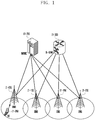
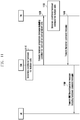
- FIG. 1 is a diagram illustrating a structure of an LTE system according to an embodiment of the disclosure.
- a radio access network in an LTE system may include a next generation base station (evolved node B, hereinafter, ENB, Node B, or base station) 1-05, 1-10, 1-15, and 1-20, a mobility management entity (MME) 1-25, and a serving-gateway (S-GW) 1-30.
- ENB next generation base station
- MME mobility management entity
- S-GW serving-gateway
- a user terminal (user equipment, hereinafter, UE or terminal) 1-35 may access an external network via the ENBs 1-05 to 1-20 and the S-GW 1-30.
- the ENBs 1-05 to 1-20 may correspond to existing Node Bs of an UMTS system.
- the ENBs are connected to a UE 1-35 via a radio channel and may perform more complex roles compared to the existing Node Bs.
- all user traffic including a real-time service such as a voice over Internet protocol (VoIP) via the Internet protocol, may be serviced through a shared channel. Therefore, there is a need for a device which collects state information, such as buffer states, available transmission power states, and channel states of UEs, to perform scheduling, and the ENBs 1-05 to 1-20 may be in charge of this.
- a single ENB may typically control multiple cells.
- the LTE system may use, for example, orthogonal frequency division multiplexing (OFDM) as a radio access technology in a 20 MHz bandwidth.
- OFDM orthogonal frequency division multiplexing
- AMC adaptive modulation & coding
- the S-GW 1-30 is a device that provides a data bearer, and may generate or eliminate a data bearer under control of the MME 1-25.
- the MME is a device in charge of various control functions as well as a mobility management function for a terminal, and may be connected to multiple base stations.
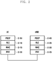
- FIG. 2 is a diagram illustrating a radio protocol structure of the LTE system according to an embodiment of the disclosure.
- the radio protocol of the LTE system may include, in a terminal and an ENB, packet data convergence protocols (PDCPs) 2-05 and 2-40, radio link controls (RLCs) 2-10 and 2-35, and medium access controls (MACs) 2-15 and 2-30, respectively.
- the PDCP may be in charge of an operation, such as IP header compression/restore. Main functions of the PDCPs may be summarized as follows.
- the radio link control (RLC) 2-10 and 2-35 may reconfigure a PDCP packet data unit (PDU) to an appropriate size so as to perform an ARQ operation or the like.
- PDU packet data unit
- the MACs 2-15 and 2-30 may be connected to multiple RLC layer devices configured in one terminal, may multiplex RLC PDUs to MAC PDUs, and may demultiplex RLC PDUs from MAC PDUs.
- Main functions of the MACs are summarized as follows.
- the NR PHY layers 2-20 and 2- 25 may perform channel-coding and modulation of upper layer data, make the channel-coded and modulated upper layer data into OFDM symbols, and transmit the OFDM symbols via a radio channel, or may perform demodulation and channel-decoding of the OFDM symbols received via the radio channel and transfer the same to an upper layer.
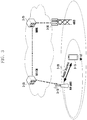
- FIG. 3 is a diagram illustrating a structure of a next-generation mobile communication system according to an embodiment of the disclosure.
- a radio access network of the next-generation mobile communication system may include a next-generation base station (new radio node B, hereinafter, NR gNB or NR base station) 3-10 and a next-generation radio core network (new radio core network, NR CN) 3-05.
- a next-generation radio user terminal (new radio user equipment, NR UE or terminal) 3-15 may access an external network via an NR gNB 3-10 and an NR CN 3-05.
- the NR gNB 3-10 may correspond to an evolved node B (eNB) of an existing LTE system.
- the NR gNB may be connected to the NR UE 3-15 via a radio channel and may provide a service superior to that of an existing Node B.
- all user traffic may be serviced via a shared channel. Therefore, there is a need for a device which collects state information, such as buffer states, available transmission power states, and channel states of UEs, to perform scheduling, and the NR NB 3-10 may be in charge of this.
- a single NR gNB may control multiple cells.
- next-generation mobile communication system in order to implement ultra-fast data transmission compared to the current LTE, a bandwidth greater than or equal to a current maximum bandwidth may be applied.
- a beam-forming technology may be additionally incorporated using orthogonal frequency division multiplexing (OFDM) as a radio access technology.
- OFDM orthogonal frequency division multiplexing
- AMC adaptive modulation & coding
- the NR CN 3-05 may perform functions, such as mobility support, bearer configuration, and QoS configuration.
- the NR CN 3c-05 is a device in charge of various control functions as well as a mobility management function for the terminal, and may be connected to multiple base stations.
- the next generation mobile communication system may be linked to the existing LTE system, and the NR CN 3c-05 may be connected to an MME 3-25 via a network interface.
- the MME 3-25 may be connected to an eNB 3-30 that is an existing base station.
- FIG. 4 is a diagram illustrating a radio protocol structure of the next-generation mobile communication system according to an embodiment of the disclosure.
- a radio protocol of the next generation mobile communication system may include NR service data adaptation protocols (SDAPs) 4-01 and 4-45, NR PDCPs 4-05 and 4-40, NR RLCs 4-10 and 4-35, and NR MACs 4-15 and 4-30 in a terminal and an NR base station, respectively.
- SDAPs NR service data adaptation protocols
- NR PDCPs 4-05 and 4-40 NR RLCs 4-10 and 4-35
- NR MACs 4-15 and 4-30 in a terminal and an NR base station, respectively.
- Main functions of the NR SDAPs 4-01 and 4-45 may include some of the following functions.
- the terminal may be configured, via a radio resource control (RRC) message, whether to use a header of the SDAP layer device or use a function of the SDAP layer device for each PDCP layer device, for each bearer, or for each logical channel.
- RRC radio resource control
- the terminal may perform indication using an access stratum (AS) QoS reflection configuration 1-bit indicator (AS reflective QoS) and a non-access stratum (NAS) quality of service (QoS) reflection configuration 1-bit indicator (NAS reflective QoS) of the SDAP header, so that the terminal updates or reconfigures mapping information on a QoS flow and a data bearer of uplink and downlink.
- the SDAP header may include QoS flow ID information indicating QoS. QoS information may be used as a data processing priority, scheduling information, etc. for supporting a smooth service.
- Main functions of the NR PDCPs 4-05 and 4-40 may include some of the following functions.
- the reordering function of an NR PDCP device may refer to a function of reordering PDCP PDUs received from a lower layer in order based on a PDCP sequence number (SN).
- the reordering function of the NR PDCP device may include a function of transferring data to an upper layer in a reordered order or include a function of directly transferring data without considering the order, and may include a function of performing reordering and recording lost PDCP PDUs, include a function of reporting states of the lost PDCP PDUs to a transmission side, and include a function of requesting retransmission of the lost PDCP PDUs.
- Main functions of the NR RLCs 4-10 and 4-35 may include some of the following functions.
- the in-sequence delivery function of an NR RLC device may refer to a function of sequentially transferring, to an upper layer, RLC SDUs received from a lower layer.
- the in-sequence delivery function of the NR RLC device may include a function of reassembling and then transferring the RLC SDUs.
- the in-sequence delivery function of the NR RLC device may include a function of reordering the received RLC PDUs according to an RLC sequence number (SN) or a PDCP sequence number (SN), may include a function of reordering and recording lost RLC PDUs, may include a function of reporting states of the lost RLC PDUs to a transmission side, and may include a function of requesting retransmission for the lost RLC PDUs.
- SN RLC sequence number
- SN PDCP sequence number
- the in-sequence delivery function of the NR RLC device may include a function of, when a lost RLC SDU exists, sequentially transferring, to the upper layer, only RLC SDUs before the lost RLC SDU.
- the in-sequence delivery function of the NR RLC device may include a function of, if a predetermined timer expires, sequentially transferring all RLC SDUs, which are received before the timer starts, to the upper layer even if a lost RLC SDU exists.
- the in-sequence delivery function of the NR RLC device may include a function of, if the predetermined timer expires, sequentially transferring all RLC SDUs, which have been received so far, to the upper layer even if a lost RLC SDU exists.
- the NR RLC device may process RLC PDUs in the order of receiving the RLC PDUs regardless of the order of sequence numbers (out-of-sequence delivery) and may transfer the processed RLC PDUs to the NR PDCP device.
- the NR RLC device may receive segments which are stored in a buffer or will be received at a later time, may perform reconfiguration into one complete RLC PDU, and then may transmit the same to the NR PDCP device.
- An NR RLC layer may not include a concatenation function, and the function may be performed in an NR MAC layer or may be replaced with a multiplexing function of the NR MAC layer.
- the out-of-sequence delivery function of the NR RLC device may refer to a function of directly transferring RLC SDUs received from a lower layer, to the upper layer regardless of order.
- the out-of-sequence delivery function of the NR RLC device may include a function of, when an original one RLC SDU is divided into multiple RLC SDUs and then received, reassembling and then transferring the RLC SDUs.
- the out-of-sequence delivery function of the NR RLC device may include a function of storing an RLC SN or PDCP SN of the received RLC PDUs, performing reordering, and recording lost RLC PDUs.
- the NR MACs 4-15 and 4-30 may be connected to multiple NR RLC layer devices included in one terminal, and main functions of the NR MACs may include some of the following functions. ⁇
- the NR PHY layers 4-20 and 4-25 may perform channel-coding and modulation of upper layer data, make the channel-coded and modulated upper layer data into OFDM symbols, and transmit the OFDM symbols via a radio channel, or may perform demodulation and channel-decoding of the OFDM symbols received via a radio channel and transfer the same to the upper layer.
- FIG. 5 is a diagram illustrating a configuration of a terminal according to an embodiment of the disclosure.
- the terminal may include a radio frequency (RF) processor 5-10, a baseband processor 5-20, a storage unit 5-30, and a controller 5-40.
- the controller 5-40 may further include a multi-connection processor 5-42.
- the RF processor 5-10 may perform a function for transmitting or receiving a signal via a radio channel, such as signal band transform and signal amplification. That is, the RF processor 5-10 may up-convert a baseband signal provided from the baseband processor 5-20 into an RF band signal, may transmit the up-converted RF band signal via an antenna, and then may down-convert the RF band signal received via the antenna into a baseband signal.
- the RF processor 5-10 may include a transmission filter, a reception filter, an amplifier, a mixer, an oscillator, a digital-to-analog convertor (DAC), an analog-to-digital convertor (ADC), and the like. In the drawing, only one antenna is illustrated, but the terminal may have multiple antennas.
- the RF processor 5-10 may include multiple RF chains. Furthermore, the RF processor 5-10 may perform beamforming. For the beamforming, the RF processor 5-10 may adjust a phase and a magnitude of each of signals transmitted or received via multiple antennas or antenna elements. The RF processor may perform MIMO, and may receive multiple layers when performing MIMO operations.
- the baseband processor 5-20 performs conversion between a baseband signal and a bitstream according to a physical layer specification of the system. For example, during data transmission, the baseband processor 5-20 generates complex symbols by encoding and modulating a transmission bitstream. When data is received, the baseband processor 5-20 reconstructs a reception bitstream via demodulation and decoding of the baseband signal provided from the RF processor 5-10.
- the baseband processor 5-20 during data transmission, the baseband processor 5-20 generates complex symbols by encoding and modulating a transmission bitstream, maps the complex symbols to sub-carriers, and then configures OFDM symbols via an inverse fast Fourier transform (IFFT) operation and cyclic prefix (CP) insertion. Further, during data reception, the baseband processor 5-20 divides the baseband signal provided from the RF processor 5-10 in units of OFDM symbols, reconstructs the signals mapped to the sub-carriers via fast Fourier transform (FFT), and then reconstructs the reception bitstream via demodulation and decoding.
- OFDM orthogonal frequency division multiplexing
- the baseband processor 5-20 and the RF processor 5-10 transmit and receive signals as described above. Accordingly, the baseband processor 5-20 and the RF processor 5-10 may be referred to as a transmitter, a receiver, a transceiver, a transceiving device, or a communication unit. Moreover, at least one of the baseband processor 5-20 and the RF processor 5-10 may include multiple communication modules to support multiple different radio access technologies. At least one of the baseband processor 5-20 and the RF processor 5-10 may include different communication modules to process signals in different frequency bands.
- the different radio access technologies may include a wireless LAN (e.g., IEEE 802.11), a cellular network (e.g., LTE), and the like.
- the different frequency bands may include a super high frequency (SHF) (e.g., 2NRHz, NRhz) band and a millimeter wave (e.g., 60 GHz) band.
- SHF super high frequency
- the storage unit 5-30 stores data, such as a default program, an application program, and configuration information, for operation of the terminal. Particularly, the storage unit 5-30 may store information related to a second access node that performs radio communication by using a second radio access technology. The storage unit 5-30 provides stored data in response to a request of the controller 5-40.
- the controller 5-40 controls overall operations of the terminal. For example, the controller 5-40 transmits or receives a signal via the baseband processor 5-20 and the RF processor 5-10. The controller 5-40 records and reads data in the storage unit 5-30. To this end, the controller 5-40 may include at least one processor. For example, the controller 5-40 may include a communication processor (CP) configured to perform control for communication and an application processor (AP) configured to control an upper layer, such as an application program.
- CP communication processor
- AP application processor
- the controller 5-40 may transmit a handover request message including a conditional handover-related target cell identifier to a target node via the transceiver, may receive, from the target node via the transceiver, a handover request response message which includes a handover command message including configuration information of a target cell for conditional handover, and may control to transmit, to the terminal via the transceiver, a radio resource control (RRC) reconfiguration message including the handover command message and condition information for the conditional handover.
- RRC radio resource control
- the condition information may be determined by the source node.
- the handover command message may be transferred via an RRC container, and the source may not modify the configuration information of the target cell included in the handover command message.
- the handover request response message may include cell identification information of the target cell for the conditional handover, and the handover command message may include a delta configuration based on source configuration information.
- the RRC reconfiguration message may include information for one or multiple cells for the conditional handover, and the condition information may be configured based on a measurement identifier (measurement identity) including a measurement object and a report configuration.
- FIG. 6 is a diagram illustrating a configuration of a base station according to an embodiment of the disclosure.
- the base station may include an RF processor 6-10, a baseband processor 6-20, a backhaul communication unit 6-30, a storage unit 6-40, and a controller 6-50.
- the controller 6-50 may further include a multi-connection processor 6-52.
- the base station may be an NR base station.
- the RF processor 6-10 may perform a function for transmitting or receiving a signal via a radio channel, such as signal band transform and signal amplification. That is, the RF processor 6-10 may up-convert a baseband signal provided from the baseband processor 6-20 into an RF band signal, may transmit the up-converted RF band signal via an antenna, and then may down-convert the RF band signal received via the antenna into a baseband signal.
- the RF processor 6-10 may include a transmission filter, a reception filter, an amplifier, a mixer, an oscillator, a DAC, an ADC, and the like. In the drawing, only one antenna is illustrated, but a first access node may include multiple antennas.
- the RF processor 6-10 may include multiple RF chains.
- the RF processor 6-10 may perform beamforming.
- the RF processor 6-10 may adjust a phase and a magnitude of each of signals transmitted or received via the multiple antennas or antenna elements.
- the RF processor may perform downlink MIMO by transmitting one or more layers.
- the baseband processor 6-20 performs a function of conversion between a baseband signal and a bitstream according to a physical layer specification of a first radio access technology. For example, during data transmission, the baseband processor 6-20 generates complex symbols by encoding and modulating a transmission bitstream. When data is received, the baseband processor 6-20 reconstructs a reception bitstream via demodulation and decoding of the baseband signal provided from the RF processor 6-10. For example, in a case of conforming to an OFDM scheme, during data transmission, the baseband processor 6-20 generates complex symbols by encoding and modulating a transmission bitstream, maps the complex symbols to sub-carriers, and then configures OFDM symbols via an IFFT operation and CP insertion.
- the baseband processor 6-20 divides the baseband signal provided from the RF processor 6-10 in units of OFDM symbols, reconstructs the signals mapped to the sub-carriers via an FFT operation, and then reconstructs the reception bitstream via demodulation and decoding.
- the baseband processor 6-20 and the RF processor 6-10 transmit and receive signals as described above. Accordingly, the baseband processor 6-20 and the RF processor 6-10 may be referred to as a transmitter, a receiver, a transceiver, a transceiving device, a communication unit, or a radio communication unit.
- the backhaul communication unit 6-30 provides an interface to perform communication with other nodes within a network. That is, the backhaul communication unit 6-30 converts, into a physical signal, a bitstream transmitted from the main base station to another node, for example, an auxiliary base station and a core network, and converts a physical signal received from the another node into a bitstream.
- the storage unit 6-40 stores data, such as a default program, an application program, and configuration information, for operation of the main base station.
- the storage unit 6-40 may store information on a bearer assigned to a connected terminal, a measurement result reported from the connected terminal, and the like.
- the storage unit 6-40 may store information serving as a criterion for determining whether to provide the terminal with multi-connectivity or to suspend multi-connectivity.
- the storage unit 6-40 provides stored data in response to a request of the controller 6-50.
- the controller 6-50 controls overall operations of the main base station. For example, the controller 6-50 transmits or receives a signal via the baseband processor 6-20 and the RF processor 6-10 or via the backhaul communication unit 6-30. The controller 6-50 records and reads data in the storage unit 6-40. To this end, the controller 6-50 may include at least one processor.
- the controller 6-50 may control to receive a handover request message including a conditional handover-related target cell identifier from a source node via the transceiver, and to transmit a handover request response message, which includes a handover command message including configuration information of a target cell for conditional handover, to the source node via the transceiver.
- a radio resource control (RRC) reconfiguration message including the handover command message and condition information for the conditional handover may be transmitted from the source node to the terminal.
- the condition information may be determined by the source node.
- the handover command message may be transferred via an RRC container, and the configuration information of the target cell included in the handover command message may not be modified in the source node.
- the handover request response message may include cell identification information of the target cell for the conditional handover, and the handover command message may include a delta configuration based on source configuration information.
- the RRC reconfiguration message may include information for one or multiple cells for the conditional handover, and the condition information may be configured based on a measurement identifier (measurement identity) including a measurement object and a report configuration.
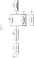
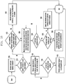
- FIG. 7 is a diagram illustrating a procedure of determining conditional handover and then transferring a condition to a corresponding target node by a source node, and generating a handover command by the target node, according to an embodiment of the disclosure.
- a resource configuration effective time may also be transferred to a corresponding target cell, and may be added to a conditional handover command so as to be transmitted to a terminal.
- a communication system may include a terminal (UE), a source node (SN), and a target node (TN).
- the source node may determine conditional handover (CHO) in 710. After the source node determines conditional handover, the source node determines a corresponding target cell and transfers an HO preparation inter node message to a target node operating the target cell, in 720.
- the source node may transfer condition information, which is to be applied to each target cell, included in the message.
- the HO preparation inter node message may be a handover request message.
- the target node finally determines a candidate target cell in consideration of handover applicability with respect to target cells given from the source node, and generates a handover command message with a configuration value to be applied during handover in the corresponding cells, in 730.
- handover execution condition information that has been transferred to the source base station may be added. Alternatively, if necessary, information that modifies this condition may be added.
- This handover command message may be transferred via a handover request ack message that is an Xn message, in 740.
- the handover command message is one RRC message and may be included in the Xn message in a form of octet string so as to be transferred to the source node.
- Configuration information in the target cell may include CFRA resources (e.g., for all wide/cell specific beams, and given delay between CHO configuration and execution), PCell (dedicated and common) configuration, T304 (to guard actual CHO execution phase i.e., started after condition is met), radioBearerConfig, RLC bearerConfig, MAC config, measConfig, etc., and these may be included as a container for each target cell within one conditional handover, or a conditional handover command may be generated for each target cell and corresponding information may be included therein. This information is applicable to all cases of FIG. 7 , FIG. 8 , FIG. 9 , FIG. 10 , and FIG. 11 .
- This (conditional) handover command message is a delta signal based on source configuration information of the terminal at the moment when the command message is transferred to the terminal. Therefore, at a point in time when the terminal receives the handover command, newly added information may be used in the target cell, wherein the newly added information is obtained by overwriting, erasing, or changing contents contained in a conditional handover command message in comparison to current configuration information of the terminal itself.
- the handover command message may be a delta signal based on the conditional handover configuration information of the target cell, which has been previously transferred to the terminal.
- the terminal always updates the configuration information for the target cell by overwriting newly received configuration information on the basis of previously received configuration information, or by erasing or replacing the previous configuration information.
- This operation is also applicable to all cases of FIG. 7 , FIG. 8 , FIG. 9 , FIG. 10 , and FIG. 11 .
- a specific factor in each octet string may have the same value for each cell, and in this case, for the convenience of a signal, a specific factor may have an indication that the specific factor is the same as another factor in an octet string list entry.
- a specific factor of a specific target cell, which has this indication, may refer to a value of a corresponding factor of another cell in an octet string list.
- the source node may transfer, as it is without separate decoding, a handover command message of the octet string, which is received from the target node, as an RRC reconfiguration message to the terminal, in 750.
- the RRC reconfiguration message may include dedicated resource configuration information of each candidate target cell and condition information that is a basis for determining execution of the conditional handover.
- the terminal having received the message starts measurement according to an added condition, and determines whether the condition is satisfied. If this condition is satisfied, the terminal performs conditional handover to a target cell that satisfies the condition.
- FIG. 8 is a diagram illustrating a procedure of directly transferring a condition for conditional handover, to a terminal by a source node, according to an embodiment of the disclosure.
- a resource configuration effective time may be also transferred to a corresponding target cell, and may be directly transferred to a terminal.
- a communication system may include a terminal (UE), a source node (SN), and a target node (TN).
- the source node may determine conditional handover (CHO) in 810. After the source node determines conditional handover, the source node determines a corresponding target cell and transfers an HO preparation inter node message to a target node operating the target cell, in 820. The source node does not transfer condition information, which is to be applied to each target cell, included in the message.
- the target node finally determines a candidate target cell in consideration of handover applicability with respect to target cells given from the source node, and generates a handover command message with a configuration value to be applied during handover in the corresponding cells, in 830.
- This handover command message may be transferred via a handover request ack message that is an Xn message, in 840.
- the handover command message is one RRC message and may be included in the Xn message in a form of an octet string so as to be transferred to the source node.
- the source node may decode the handover command message of the octet string received from the target node, to check each target cell, and may add a condition for conditional handover to the corresponding target cell for each cell, in 850.
- the source node adds the condition for conditional handover for each cell, and then, via performing encoding, transfers the condition in an RRC Reconfiguration message back to the terminal, in 860.
- the RRC reconfiguration message may include dedicated resource configuration information of each candidate target cell and condition information that is a basis for determining execution of the conditional handover.
- the terminal having received the RRC reconfiguration message starts measurement according to an added condition, and determines whether the condition is satisfied. If this condition is satisfied, the terminal may perform conditional handover to a target cell that satisfies the condition.
- the source node transmits an RRC reconfiguration message to the terminal, but this corresponds to an example of an RRC message, and other RRC messages may be used.
- a radio access technology (RAT) of a source node of the disclosure is LTE
- the RRC message may be an RRC connection reconfiguration message.
- FIG. 9 is a diagram illustrating an operation of additionally adding, by a source node, control information for the source node to a conditional handover command generated from a target node, according to an embodiment of the disclosure.
- a resource configuration effective time may also be transferred to a corresponding target cell, and may be added to a conditional handover command, or may be added to a separate field by the source node so as to be transmitted to a terminal.
- a communication system may include a terminal (UE), a source node (SN), and a target node (TN).
- the source node may determine conditional handover (CHO) in 910. After the source node determines conditional handover, the source node determines a corresponding target cell and transfers an HO preparation inter node message to a target node operating the target cell, in 920.
- the HO preparation inter node message may be a handover request message.
- the source node does not transfer condition information, which is to be applied to each target cell, included in this message.
- the target node finally determines, with respect to target cells given from the source node, a candidate target cell in consideration of handover applicability, and generates a handover command message with a configuration value to be applied during handover in the corresponding cells, in 930.
- the handover command message is transferred via a handover request ack message that is an Xn message, in 940.
- the handover command message is an RRC message and may be included in the Xn message in a form of an octet string so as to be transferred to the source node.
- the handover command message may be included in the Xn message in a form of an octet string list.
- the source node may add information controlled by the source node to a separate field, which is separate from the handover command message of the octet string received from the target node, in 950.
- the octet string received from the target cell is not decoded, and a condition for performing conditional handover and other information for controlling the terminal by the source node are added to the separate field. Since the octet string is not decoded, the source node does not modify the handover command message received from the target node or information included in the handover command message.
- Information that may be added to the separate field may be information requiring reconfiguration in the current source cell or common condition information for all or some group target cells, rather than a configuration of conditional handover.
- the source node may transfer, to the target node, the condition for conditional handover, and the target node may generate a conditional handover command including the condition, and make the same into an octet string so as to transfer the octet string back to the source node.
- the aforementioned separate field for information controlled by the source node may not include the condition of conditional handover, and configuration information for terminal configuration in the current source node may be included.
- the source node transfers, after encoding procedure, the field as an information element separate from the octet string to the terminal by a single integrated RRC reconfiguration message, in 960.
- This RRC reconfiguration message may include dedicated resource configuration information of a candidate target cell of each or specific group, condition information that is a basis for determining to perform conditional handover, and terminal configuration information required in the current source cell, which is unrelated to conditional handover.
- the terminal having received the message applies terminal configuration required in the source cell, and updates and stores configuration information in the target cell for conditional handover. Measurement according to the added condition for conditional handover may be started, and whether the condition is satisfied may be determined. If the condition is satisfied the terminal may perform conditional handover to a target cell that satisfies the condition.
- Table 1 below shows an example of an ASN.1 code of an RRCReconfiguration message generated in this manner.
- RRCReconfig msg :: seq ⁇ sn_Control_part SN_control, tn_HO_CMD octect string ⁇ Handover Command ⁇ , ⁇
- SN_control is terminal control information added separately by the source node, and may include condition information for handover.
- tn_HO_CMD is a handover command octet string for conditional handover, which is received from the target node.
- CGI for multiple target cells should be added to a target cell global ID field of a HANDOVER REQUEST message transferred to an Xn interface.
- Table 2 shows contents of the target cell global ID field in the HANDOVER REQUEST message.
- the handover request message may include conditional handover information or conditional handover indication information.
- IE/Group Name Presence Rang e IE type and reference semantics description Criticality Assigned Criticality Target Cell Global ID M 9.2.3.25 includes either an E-UTRA CGI or an NR CGI YES reject
- FIG. 10 is a diagram illustrating an operation of adding multiple cells to one conditional handover command when a source node prepares conditional handover for multiple cells according to an embodiment of the disclosure.
- a communication system may include a terminal (UE), a source node (SN), and a target node (TN).
- the source node may determine conditional handover (CHO) in 1010.
- the source node may request the target node to prepare handover for multiple target cells, in 1020.
- the source node may transmit, to the target node, a handover preparation message (handover preparation INM message) including a condition for each cell or group of cells.
- the target node When the target node generates a handover command for a target cell, the target node may generate handover commands for respective target cells, instead of generating one handover command, in 1030.
- Each handover command is one octet string, and may be included as a separate octet string in a HANDOVER REQUEST ACKNOWLEDGE message transmitted from the target node to the source node, in 1040.
- a target NG-GAN node to Source NG-RAN node Transparent container field below may have a separate octet string on the basis of target cell global IDs or indices of candidate target cells determined in each target node.
- a target cell CGI list or an index list of the determined target cells may be added to the HANDOVER REQUEST ACKNOWLEDGE message, and a transparent container field below may include multiple octet strings in the order of a corresponding list.
- the condition for each target cell may be included in each handover command.
- the source node may generate an RRC reconfiguration message including each handover command received from the target node, so as to transmit the generated RRC reconfiguration message to the terminal, in 1050.
- the source node does not need to decode the handover command received from the target node.
- FIG. 11 is a diagram illustrating an operation of, when a source node prepares conditional handover for a multi-cell, adding one cell to one conditional handover command, according to an embodiment of the disclosure.
- a communication system may include a terminal (UE), a source node (SN), and a target node (TN).
- the source node may determine conditional handover (CHO) in 1110.
- the source node requests the target node to prepare handover for multiple target cells, in 1120.
- the source node may transmit, to the target node, a handover preparation message (handover preparation INM message) including a condition for each cell or group of cells.
- the target node may generate handover commands by adding, to one handover command, dedicated configuration information and handover condition configuration information for multiple candidate target cells, in 1130.
- information on multiple target cells is included in the handover command message, but is expressed as one octet string, so that a target cell selected as a candidate target cell cannot be unknown in a HANDOVER REQUEST ACKNOWLEDGE Xn message.
- the target node may transmit, to the source node, an Xn message carrying the handover command message expressed as a single octet string, in 1140.
- the source node transfers, without decoding, an RRC Reconfiguration message including this handover command message to the terminal, in 1150.
- FIG. 12 is a diagram illustrating an operation relating to determining a field in RRC reconfiguration information, to which multi-target cell information is to be added, according to an embodiment of the disclosure.
- a handover command message when one handover command message is included in an RRC Reconfiguration message given to a terminal, if this message includes information on multiple candidate target cells, options for a detailed location for configuration of a condition may be provided.
- a first option is that a handover command message is included in SpcellConfig IE, but is located outside reconfigWithSync.
- a second option is that a handover command message is included in reconfigWithSync iE, but is located outside spcellConfigCommon.
- a third option is that a handover command message is located inside spcellConfigCommon IE.
- a last option is a method in which a handover command message is located inside cellGroupConfig and is located outside SpcellConfig.
- a handover command message may be located inside measConfig IE, wherein each condition is displayed with a candidate target cell ID, that is, a physical cell ID or CGI.
- dedicated resource configuration information for each candidate target cell may be multi-listed at an SpcellConfig level by including target cell id information in SpcellConfig.
- target cell id information in a reconfigWithSync level may be included in the dedicated configuration information of each target cell.
- the dedicated configuration information of each target cell may be added to reconfigWithSync, and common configuration information for a cell may be located outside reconfigWithSync of SpcellConfig without a target cell id.
- the dedicated configuration information for each target cell may be transferred to SpcellConfigCommon by using a target cell id.
- dedicated resource configuration information of a corresponding target cell may be transferred to the terminal.
- each method is necessary for a method to reduce signal overhead.
- the current source cell and each target cell or a specific target cell group the following options are possible.
- Parts that are changeable in the options may be, for example, an event type or an offset value used in each event type, threshold values of a serving cell and a target cell, an offset value for each frequency, an offset value for each cell, serving cell and target cell frequencies to be measured, subcarrier spacing information, SMTC information, a reference signal type, a maximum number of RSs or beams required for beam consolidation, a threshold value of beam-specific reception intensity for determination of each measurement beam, and the like.
- FIG. 13 is a signal flow diagram in a case where only a beam level condition is given to a terminal without a cell level condition, which corresponds to 2-1th and 2-2th embodiments according to an embodiment of the disclosure.
- a source node serving base station
- the source node may transmit a message for requesting conditional handover preparation to a target node, in 1310.
- the message for requesting conditional handover preparation may include an indication of a handover message for conditional handover.
- the message for requesting conditional handover preparation may include a beam-based condition configuration and a cell id of a candidate cell for conditional handover.
- the target node having received the message for requesting conditional handover preparation may determine whether a target cell indicated by the serving node is able to perform conditional handover, and may generate a conditional handover command message by adding dedicated resource configuration information to be used in the target cell, in 1315.
- the conditional handover command message may include beam level condition configuration information for candidate target cells capable of performing conditional handover.
- the target node may transfer the generated conditional handover command message to the source node, in 1320.
- the source node may transfer the conditional handover command received from the target node to a terminal via an RRCReconfiguration message, in 1325. If the source node has transferred no beam level configuration condition information to the target node during previous handover preparation, the handover command message may not include a beam level configuration condition, and in this case, the source node may directly add, to the RRCReconfiguration message, a beam level configuration condition applied to each of candidate target nodes, so as to transfer the beam level configuration condition to the terminal.
- the terminal having received the RRCReconfiguration message may start measuring intensities of beams configured in the source cell and each target cell with respect to beams configured for a beam level condition configuration, and may evaluate whether the measured intensities of the beams satisfy the beam level condition, in 1330, 1335, and 1340.
- the terminal may perform conditional handover to the target cell satisfying the beam level condition, in 1345.
- the terminal may perform random access to the target cell selected to perform conditional handover, in 1350.
- a serving base station may transmit a configuration for conditional handover to a terminal.
- the serving base station may configure a beam intensity-based event condition with respect to each candidate target cell or candidate target cell group subject to handover.
- configuration information of the beam intensity-based condition specific beams of the serving cell, i.e., N beam indices of synchronization signal blocks (SSBs) or channel state information reference signals (CSI-RSs), and/or M specific beams of a corresponding target cell, i.e., indices of SSBs or CSI-RSs, may be given to the terminal.
- An evaluation condition for comparison between the beams of the serving cell and the beams of the target cell may be given to the terminal.
- RSRP reference signal received power
- RSRQ reference signal received quality
- RSSI received signal strength indicator
- Rs-SINR reference signal-to-interference-and-noise ratio
- type A1 There may be type A1 as a beam intensity evaluation condition.
- a threshold value for comparison with a beam intensity value may be configured for the terminal.
- the terminal may measure reception intensities of configured N beams of the serving cell, and if an average value of the intensities of the N beams, a minimum value among the intensities of the N beams, or a maximum value among the intensities of the N beams of the serving cell is greater than the given threshold value, the terminal consider that event A1 is satisfied.
- a threshold value to be compared with a beam intensity value may be configured for the terminal.
- the terminal may measure reception intensities of configured N beams of the serving cell, and if an average value of the intensities of the N beams, a minimum value among the intensities of the N beams, or a maximum value among the intensities of the N beams of the serving cell is smaller than the given threshold value, the terminal consider that event A2 is satisfied.
- an offset value for comparison between a beam intensity of the serving cell and a beam intensity of the target cell may be configured for the terminal.
- the terminal may measure reception intensities of configured N beams of the serving cell and reception intensities of configured M beams of the target cell, and if an average value of the intensities of the N beams of the serving cell is smaller than an average value of the intensities of the M beams of the target cell by an offset, the terminal may consider that event A3 is satisfied.
- the terminal may consider that event A3 is satisfied.
- the terminal may consider that event A3 is satisfied.
- type A4 There may be type A4 as another beam intensity evaluation condition.
- a threshold value for comparison with a beam intensity value may be configured for the terminal.
- the terminal may measure reception intensities of configured M beams of the target cell, and if an average value of the intensities of the M beams, a minimum value among the intensities of the M beams, or a maximum value among the intensities of the M beams of the target cell is greater than the given threshold, the terminal may consider that event A4 is satisfied.
- a threshold value for comparison with a beam intensity value of the serving cell and a threshold value for comparison with a beam intensity value of the target cell may be configured for the terminal.
- the terminal may measure reception intensities of configured N beams of the serving cell and may measure reception intensities of configured M beams of the target cell, wherein if an average value of the intensities of the N beams, a maximum value among the intensities of the N beams, or a minimum value among the intensities of the N beams of the serving cell is smaller than the threshold value for the serving cell, and if an average value of the intensities of the M beams, a minimum value among the intensities of the M beams, or a maximum value among the intensities of the M beams of the target cell is greater than the given threshold value, the
- the parameter related to type A3 may include a serving cell-specific offset and a measurement object-specific offset of the serving cell, and values of these parameters may be added to a serving cell part of the offset of type A3 described above.
- the parameter related to type A3 may also include a target cell-specific offset and a measurement object-specific offset of the target cell, and values of these parameters may be added to a target cell part of the offset of type A3 described above.
- the parameter related to type A4 may include a target cell-specific offset and a measurement object-specific offset of the target cell, and values of these parameters may be added to value parts of the target beams so as to be used for comparison with the threshold value of type A4 mentioned above.
- the parameters related to type A5 may include a target cell-specific offset and a measurement object-specific offset of the target cell, and values of these parameters may be added to value parts of the target beams so as to be used for comparison with the threshold value for the target cell of type A5 mentioned above.
- a serving base station may transmit a configuration for conditional handover to a terminal.
- the serving base station may configure a beam intensity-based event condition for the terminal, with respect to each candidate target cell or candidate target cell group subject to handover.
- configuration information of the beam intensity-based condition N which is the number of beams to be considered for an event determination condition in the serving cell and/or M which is the number of beams to be considered in an event determination condition for a target cell may be given to the terminal.
- Configuration information on a reference signal (RS) type of each beam, which is to be considered in the serving cell and/or the target cell, may also be transferred to the terminal.
- RS reference signal
- the configuration information on an RS type may be information indicating that an RS type of each beam is SSB or CSI-RS.
- An evaluation condition for comparison between beams of the serving cell and beams of the target cell may be given to the terminal.
- RSRP, RSRQ, RSSI, or Rs-SINR may be considered. If the information on the number of beams described above is given to the terminal, the terminal may start measuring all beams corresponding to a corresponding RS type and may determine whether the measured beams satisfy the evaluation condition. If the beams of the target cell satisfy the given condition, the terminal may perform handover to the target cell satisfying the condition.
- a threshold value for comparison with a beam intensity value may be configured for the terminal.
- the terminal may measure reception intensities of all beams of the serving cell, and if an average value of the intensities of the N beams having the greatest reception intensity in order among the measured beams of the serving cell, a minimum value among the intensities of the N beams having the greatest reception intensity in order, or a maximum value among the intensities of the N beams having the greatest reception intensity in order is greater than the given threshold value, the terminal may consider that event A1 is satisfied.
- a threshold value for comparison with a beam intensity value may be configured for the terminal.
- the terminal may measure reception intensities of all beams of the serving cell, and if an average value of the intensities of the N beams having the greatest reception intensity in order among the measured beams of the serving cell, a minimum value among the intensities of the N beams having the greatest reception intensity in order, or a maximum value among the intensities of the N beams having the greatest reception intensity in order is smaller than the given threshold value, the terminal may consider that event A2 is satisfied.
- an offset value for comparison between a beam intensity of the serving cell and a beam intensity of the target cell may be configured for the terminal.
- the terminal may measure reception intensities of all beams of the serving cell and reception intensities of all beams of the target cell, and if an average value of the intensities of the N beams having the greatest reception intensity in order among the measured beams of the serving cell is smaller than an average value of the intensities of the M beams having the greatest reception intensity in order among the measured beams of the target cell by an offset, the terminal may consider that event A3 is satisfied.
- the terminal may consider that event A3 is satisfied.
- the terminal may consider that event A3 is satisfied.
- a threshold value for comparison with a beam intensity value may be configured for the terminal.
- the terminal may measure reception intensities of all beams of the target cell, and if an average value of the intensities of the M beams having the greatest reception intensity in order among the measured beams of the target cell, a minimum value among the intensities of the M beams having the greatest reception intensity in order, or a maximum value among the intensities of the M beams having the greatest reception intensity in order is greater than the given threshold value, the terminal may consider that event A4 is satisfied.
- a threshold value for comparison with a beam intensity value of the serving cell and a threshold value for comparison with a beam intensity value of the target cell may be configured for the terminal.
- the terminal may measure reception intensities of all beams of the serving cell and may measure reception intensities of all beams of the target cell, wherein if an average value of the intensities of N beams having the greatest reception intensity in order among the measured beams of the serving cell, a maximum value among the intensities of the N beams having the greatest reception intensity in order, or a minimum value among the intensities of the N beams having the greatest reception intensity in order is smaller than the threshold value for the serving cell, and if an average value of the intensities of M beams having the greatest reception intensity in order among the measured beams of the target cell, a minimum value among the intens
- the parameter related to type A3 may include a serving cell-specific offset and a measurement object-specific offset of the serving cell, and values of these parameters may be added to a serving cell part of the offset of type A3 mentioned above.
- the parameter related to type A3 may also include a target cell-specific offset and a measurement object-specific offset of the target cell, and values of these parameters may be added to a target cell part of the offset of type A3 mentioned above.
- the parameter related to type A4 may include a target cell-specific offset and a measurement object-specific offset of the target cell, and values of these parameters may be added to value parts of the target beams so as to be used for comparison with the threshold value of type A4 mentioned above.
- the parameters related to type A5 may include a target cell-specific offset and a measurement object-specific offset of the target cell, and values of these parameters may be added to value parts of the target beams so as to be used for comparison with the threshold value for the target cell of type A5 mentioned above.
- FIG. 14 is a signal flow diagram in a case where both a cell level condition and a beam level condition are given to a terminal, which corresponds to 2-3th and 2-4th embodiments according to an embodiment of the disclosure.
- a source node may determine to perform conditional handover (CHO), in 1405. Then, the source node may transmit a message for requesting conditional handover preparation to a target node, in 1410.
- the message for requesting conditional handover preparation may include an indication of a handover message for conditional handover.
- the message for requesting conditional handover preparation may include a cell id and cell-based and beam-based condition configurations for a candidate cell of conditional handover.
- the target node having received the message for requesting conditional handover preparation may determine whether a target cell indicated by the serving node is able to perform conditional handover, and may generate a conditional handover command message by adding dedicated resource configuration information to be used in the target cell, in 1415.
- the conditional handover command message may include cell level and beam level condition configuration information for candidate target cells capable of performing conditional handover.
- the target node may transfer the generated conditional handover command message to the source node, in 1420.
- the source node may transfer the conditional handover command received from the target node to a terminal via an RRCReconfiguration message, in 1425. If the source node has transferred no cell level and beam level configuration condition information to the target node during previous handover preparation, the handover command message may not include cell level and beam level configuration conditions, and in this case, the source node may directly add, to the RRCReconfiguration message, cell level and beam level configuration conditions applied to each of candidate target nodes, so as to transfer the cell level and beam level configuration conditions to the terminal.
- the terminal having received the RRCReconfiguration message may start measuring intensities of beams configured for the cell level and beam level conditions for each candidate target cell and source cell, and may evaluate whether the measured intensities of the beams satisfy the cell level and beam level conditions, in 1430, 1435, and 1440.
- the terminal may determine again whether the target cell satisfying the cell level condition satisfies the beam level condition configured for the target cell, and if a target cell satisfying even the beam level condition exists, the terminal may perform conditional handover to the target cell, in 1445.
- the terminal may perform random access to the target cell selected to perform conditional handover, in 1450.
- a serving base station may transmit a configuration for conditional handover to a terminal.
- the serving base station may concurrently configure a cell intensity-based condition and a beam intensity-based condition with respect to each candidate target cell or candidate target cell group subject to handover.
- the cell intensity-based condition may include report configuration information and measurement object information for determination of A1, A2, A3, A4, A5, and A6 events and corresponding events in LTE and NR standards and beam consolidation-related configurations (RS type, threshold value for determining a reception intensity of each beam, maximum number of beams to be considered for cell intensity among beams having a value exceeding the threshold value, etc.).
- the serving base station may configure the beam intensity-based event condition to the terminal.
- specific beams of the serving cell i.e., N beam indices of synchronization signal blocks (SSBs) or channel state information reference signals (CSI-RSs), and/or M specific beams of a corresponding target cell, i.e., indices of SSBs or CSI-RSs
- An evaluation condition for comparison between beams of the serving cell and beams of the target cell may be given to the terminal.
- RSRP, RSRQ, RSSI, or Rs-SINR may be considered. If the aforementioned beam information is given to the terminal, the terminal may start beam measurement and may determine whether a measured beam satisfies the evaluation condition.
- the terminal may perform handover to the target cell satisfying both conditions.
- Cell and beam intensity measurement may be performed when corresponding cell and beam intensity-based condition configuration information is given. If there are multiple target cells satisfying the cell intensity-based condition at the same time, the terminal may preferentially perform handover to a target cell satisfying the given beam intensity-based condition among target cells satisfying the cell intensity-based condition.
- type A1 There may be type A1 as a beam intensity evaluation condition.
- a threshold value for comparison with a beam intensity value may be configured for the terminal.
- the terminal may measure reception intensities of configured N beams of the serving cell, and if an average value of the intensities of the N beams, a minimum value among the intensities of the N beams, or a maximum value among the intensities of the N beams of the serving cell is greater than the given threshold value, the terminal may consider that event A1 is satisfied.
- a threshold value for comparison with a beam intensity value may be configured for the terminal.
- the terminal may measure reception intensities of configured N beams of the serving cell, and if an average value of the intensities of the N beams, a minimum value among the intensities of the N beams, or a maximum value among the intensities of the N beams of the serving cell is smaller than the given threshold value, the terminal may consider that event A2 is satisfied.
- an offset value for comparison between a beam intensity of the serving cell and a beam intensity of the target cell may be configured for the terminal.
- the terminal may measure reception intensities of configured N beams of the serving cell and reception intensities of configured M beams of the target cell, and if an average value of the intensities of the N beams of the serving cell is smaller than an average value of the intensities of the M beams of the target cell by an offset, the terminal may consider that event A3 is satisfied.
- the terminal may consider that event A3 is satisfied.
- the terminal may consider that event A3 is satisfied.
- type A4 There may be type A4 as another beam intensity evaluation condition.
- a threshold value for comparison with a beam intensity value may be configured for the terminal.
- the terminal may measure reception intensities of configured M beams of the target cell, and if an average value of the intensities of the M beams, a minimum value among the intensities of the M beams, or a maximum value among the intensities of the M beams of the target cell is greater than the given threshold value, the terminal may consider that event A4 is satisfied.
- a threshold value for comparison with a beam intensity value of the serving cell and a threshold value for comparison with a beam intensity value of the target cell may be configured for the terminal.
- the terminal may measure reception intensities of configured N beams of the serving cell and may measure reception intensities of configured M beams of the target cell, wherein if an average value of the intensities of the N beams, a maximum value among the intensities of the N beams, or a minimum value among the intensities of the N beams of the serving cell is smaller than the threshold value for the serving cell, and if an average value of the intensities of the M beams, a minimum value among the intensities of the M beams, or a maximum value among the intensities of the M beams of the target cell is greater than the given threshold value, the
- the parameter related to type A3 may include a serving cell-specific offset and a measurement object-specific offset of the serving cell, and values of these parameters may be added to a serving cell part of the offset of type A3 described above.
- the parameter related to type A3 may also include a target cell-specific offset and a measurement object-specific offset of the target cell, and values of these parameters may be added to a target cell part of the offset of type A3 mentioned above.
- the parameter related to type A4 may include a target cell-specific offset and a measurement object-specific offset of the target cell, and values of these parameters may be added to value parts of the target beams (e.g., beams configured to be measured in the target cell) so as to be used for comparison with the threshold value of type A4 mentioned above.
- the parameters related to type A5 may include a target cell-specific offset and a measurement object-specific offset of the target cell, and values of these parameters may be added to value parts of the target beams so as to be used for comparison with the threshold value for the target cell of type A5 mentioned above.
- contention-free random access may be performed using dedicated random access configuration information for specific beams of a corresponding target cell.
- Configuration information for contention-free random access may include an index of a beam capable of transmitting a contention-free RACH preamble, contention-free preamble information to be used in the beam, time/frequency information used for preamble transmission in the beam, threshold value information to be considered when performing contention-free random access if a beam, the intensity of which exceeds a specific threshold value, exists among corresponding beams, and the like.
- the target cell for which conditional handover preparation has been requested may configure contention-free random access resources for specific beams, and may add, to a corresponding conditional handover command, a cell-based condition and a beam intensity-based condition for the target cell so as to transmit the conditional handover command to the terminal.
- the source cell may receive the information of the target cell and transmit the cell-based and beam intensity-based conditions to the terminal.
- Information of the beam-based condition may be as follows.
- the terminal For each target cell, the terminal may be notified of, as the beam intensity-based condition, an evaluation condition of type A4 and beam index information configured to enable transmission of a contention free random access preamble as index information of M beams of the target cell, which is to be used for evaluation of type A4, and the terminal may be notified of, as a threshold value of type A4, a threshold value for beam evaluation when contention-free random access is performed.
- the terminal may evaluate the cell-based condition, may preferentially select, among cells satisfying the cell-based condition, target cells satisfying the beam intensity-based condition of type A4 from among cells for which contention-free random access has been configured, and may perform conditional handover to one of the selected cells.
- a serving base station may transmit a configuration for conditional handover to a terminal.
- the serving base station may concurrently configure a cell intensity-based condition and a beam intensity-based condition with respect to each candidate target cell or candidate target cell group subject to handover.
- the cell intensity-based condition may include report configuration information and measurement object information for determination of A1, A2, A3, A4, A5, and A6 events and corresponding events in LTE and NR standards and beam consolidation-related configurations (RS type, threshold value for determining a reception intensity of each beam, maximum number of beams to be considered for cell intensity among beams having a value exceeding the threshold value, etc.).
- the serving base station may configure the beam intensity-based event condition to the terminal.
- N which is the number of beams to be considered for an event determination condition in the serving cell and/or M which is the number of beams to be considered in an event determination condition for a target cell
- Configuration information on a reference signal (RS) type of each beam, which is to be considered in the serving cell and/or the target cell may also be transferred to the terminal.
- the configuration information on an RS type may be information indicating that an RS type of each beam is SSB or CSI-RS.
- An evaluation condition for comparison between beams of the serving cell and beams of the target cell may be given to the terminal.
- RSRP, RSRQ, RSSI, or Rs-SINR may be considered. If the information on the number of beams described above is given to the terminal, the terminal may start measuring all beams corresponding to a corresponding RS type and may determine whether the measured beams satisfy the evaluation condition.
- the terminal may perform handover to the target cell satisfying both conditions.
- Cell and beam intensity measurement may be performed when corresponding cell and beam intensity-based condition configuration information is given. If there are multiple target cells satisfying the cell intensity-based condition at the same time, the terminal may preferentially perform handover to a target cell satisfying the given beam intensity-based condition among target cells satisfying the cell intensity-based condition.
- a threshold value for comparison with a beam intensity value may be configured for the terminal.
- the terminal may measure reception intensities of all beams of the serving cell, and if an average value of the intensities of the N beams having the greatest reception intensity in order among the measured beams of the serving cell, a minimum value among the intensities of the N beams having the greatest reception intensity in order, or a maximum value among the intensities of the N beams having the greatest reception intensity in order is greater than the given threshold value, the terminal may consider that event A1 is satisfied.
- a threshold value for comparison with a beam intensity value may be configured for the terminal.
- the terminal may measure reception intensities of all beams of the serving cell, and if an average value of the intensities of the N beams having the greatest reception intensity in order among the measured beams of the serving cell, a minimum value among the intensities of the N beams having the greatest reception intensity in order, or a maximum value among the intensities of the N beams having the greatest reception intensity in order is smaller than the given threshold value, the terminal may consider that event A2 is satisfied.
- an offset value for comparison between a beam intensity of the serving cell and a beam intensity of the target cell may be configured for the terminal.
- the terminal may measure reception intensities of all beams of the serving cell and reception intensities of all beams of the target cell, and if an average value of the intensities of the N beams having the greatest reception intensity in order among the measured beams of the serving cell is smaller by an offset than an average value of the intensities of the M beams having the greatest reception intensity in order among the measured beams of the target cell, the terminal may consider that event A3 is satisfied.
- the terminal may consider that event A3 is satisfied.
- the terminal may consider that event A3 is satisfied.
- a threshold value for comparison with a beam intensity value may be configured for the terminal.
- the terminal may measure reception intensities of all beams of the target cell, and if an average value of the intensities of the M beams having the greatest reception intensity in order among the measured beams of the target cell, a minimum value among the intensities of the M beams having the greatest reception intensity in order, or a maximum value among the intensities of the M beams having the greatest reception intensity in order is greater than the given threshold value, the terminal may consider that event A4 is satisfied.
- a threshold value for comparison with a beam intensity value of the serving cell and a threshold value for comparison with a beam intensity value of the target cell may be configured for the terminal.
- the terminal may measure reception intensities of all beams of the serving cell and may measure reception intensities of all beams of the target cell, wherein if an average value of the intensities of N beams having the greatest reception intensity in order among the measured beams of the serving cell, a maximum value among the intensities of the N beams having the greatest reception intensity in order, or a minimum value among the intensities of the N beams having the greatest reception intensity in order is smaller than the threshold value for the serving cell, and if an average value of the intensities of M beams having the greatest reception intensity in order among the measured beams of the target cell, a minimum value among the intens
- the parameter related to type A3 may include a serving cell-specific offset and a measurement object-specific offset of the serving cell, and values of these parameters may be added to a serving cell part of the offset of type A3 mentioned above.
- the parameter related to type A3 may also include a target cell-specific offset and a measurement object-specific offset of the target cell, and values of these parameters may be added to a target cell part of the offset of type A3 mentioned above.
- the parameter related to type A4 may include a target cell-specific offset and a measurement object-specific offset of the target cell, and values of these parameters may be added to value parts of the target beams so as to be used for comparison with the threshold value of type A4 mentioned above.
- the parameters related to type A5 may also include a target cell-specific offset and a measurement object-specific offset of the target cell, and values of these parameters may be added to value parts of the target beams so as to be used for comparison with the threshold value for the target cell of type A5 mentioned above.
- the terminal may perform conditional handover according to implementation of the terminal or in the order of cells having the greatest reception intensity of beams of a target cell; 2) if there is a cell satisfying the beam-level condition for each cell, the terminal may perform conditional handover to the cell; or 3) if there are multiple cells satisfying the beam-level condition for each cell, the terminal may perform conditional handover according to implementation of the terminal or in the order of cells having the greatest reception intensity of beams of the target cell
- an indication to consider a contention free RACH (CFRA) configuration as a beam level condition may be transferred to the terminal via an RRCReconfiguration message carrying a conditional handover command. That is, if the terminal receives an indication to consider a CFRA configuration as a beam level condition for a specific target cell or target cell group, the terminal may, after performing cell and beam measurement, if there are multiple target cells satisfying a cell level condition, consider, with respect to the target cells, the CFRA configuration (i.e., SSB/CSI-Rs id indicating a beam the intensity of which is to be considered, RSRP threshold, etc.) as a beam-based condition of the target cells.
- the CFRA configuration i.e., SSB/CSI-Rs id indicating a beam the intensity of which is to be considered, RSRP threshold, etc.
- the target cell may be considered to satisfy the beam level condition. If there are multiple cells satisfying the beam level condition, the terminal may perform handover to a cell having the greatest cell level reception intensity from among the cells satisfying the beam level condition, or may select a cell to perform conditional handover according to a terminal implementation method.
- FIG. 15 is a signal flow diagram of a procedure of performing conditional handover when a CFRA configuration is used as a beam level condition configuration, according to an embodiment of the disclosure.
- a source node may determine to perform conditional handover, in 1505. Then, the source node may transmit a message for requesting conditional handover preparation to a target node, in 1510.
- the message for requesting conditional handover preparation may include an indication of a handover message for conditional handover.
- the message for requesting conditional handover preparation may include a cell id and cell-based and beam-based condition configurations for a candidate cell of conditional handover.
- the target node having received the message for requesting conditional handover preparation may determine whether a target cell indicated by the serving node is able to perform conditional handover, and may generate a conditional handover command message by adding dedicated resource configuration information to be used in the target cell, in 1515.
- the conditional handover command message may include cell level and beam level condition configuration information for candidate target cells capable of performing conditional handover. If CFRA configuration information is configured for a specific target cell, the conditional handover command message may include an indication to use the CFRA configuration information instead of beam level condition configuration information with respect to the target cell, instead of including the beam level condition configuration information.
- the target node may transfer the generated conditional handover command message to the source node, in 1520.
- the source node may transfer the conditional handover command received from the target node to a terminal via an RRCReconfiguration message, in 1525. If the source node has transferred no cell level and beam level configuration condition information to the target node during previous handover preparation, the handover command message may not include cell level and beam level configuration conditions, and in this case, the source node may directly add, to the RRCReconfiguration message, cell level and beam level configuration conditions applied to each of candidate target nodes, so as to transfer the cell level and beam level configuration conditions to the terminal.
- the terminal having received the RRCReconfiguration message may start measuring intensities of beams configured for the cell level and beam level conditions for each candidate target cell and source cell, and may evaluate whether the measured intensities of the beams satisfy the cell level and beam level conditions, in 1530, 1535, and 1540. If the conditional handover command message transferred via the RRCReconfiguration message indicates that the beam level condition configuration information is replaced with the CFRA configuration information, the terminal may evaluate whether an event of type A4 (i.e., a case where a maximum value among the intensities of beams configured for the target cell exceeds a rsrpThresh threshold value), to which the threshold value of rsrpThresh has been applied, is satisfied with respect to beams configured as monitoring beams configured for CFRA.
- an event of type A4 i.e., a case where a maximum value among the intensities of beams configured for the target cell exceeds a rsrpThresh threshold value
- the terminal may determine again whether the target cell satisfying the cell level condition satisfies the beam level condition (a case where there is an indication to use CFRA as the beam level condition, the A4 type event) configured for the target cell, and if a target cell satisfying even the beam level condition exists, the terminal may perform conditional handover to the target cell, in 1545.
- the terminal may perform random access to the target cell selected to perform conditional handover, in 1550.
- FIG. 16 is a diagram illustrating an operation of performing conditional handover in a terminal in consideration of beam level and cell level conditions, according to an embodiment of the disclosure.
- a terminal receives in 1605 a conditional handover (CHO) command
- the terminal may determine in 1610 whether the received command includes only a cell level condition, or includes a beam level condition as well. If the conditional handover command includes only the cell level condition, the terminal may perform in 1615 signal intensity measurement for reference signals configured for cell level reception intensity measurement with respect to each of candidate target cells and a serving cell. If, during signal intensity measurement, a cell satisfying the cell level condition is discovered in 1620, the terminal may perform conditional handover to the cell in 1625.
- CHO conditional handover
- the terminal may measure in 1635 intensities of reference signals (RSs) for beam level intensity measurement and the RSs for cell level intensity measurement configured for the candidate target cells and the source cell. If the cell level condition is satisfied in 1640, the terminal may determine, for only cells satisfying the cell level condition, whether the given beam level condition of each cell is satisfied, in 1645. If there are cells that also satisfy the beam level condition, the terminal may select one of the cells so as to perform conditional handover, in 1650. If the cell level condition is satisfied but there is no cell satisfying the beam level condition, the terminal may select one cell from among target cells satisfying the cell level condition so as to perform conditional handover, in 1655. If the conditional handover command does not include the cell level condition or the beam level condition, the terminal may perform only reconfiguration thereof by using other reconfiguration information, in 1660.
- RSs reference signals
- a computer-readable storage medium for storing one or more programs (software modules) may be provided.
- the one or more programs stored in the computer-readable storage medium may be configured for execution by one or more processors within the electronic device.
- the at least one program may include instructions that cause the electronic device to perform the methods according to various embodiments of the disclosure as defined by the appended claims and/or disclosed herein.
- the programs may be stored in non-volatile memories including a random access memory and a flash memory, a read only memory (ROM), an electrically erasable programmable read only memory (EEPROM), a magnetic disc storage device, a compact disc-ROM (CD-ROM), digital versatile discs (DVDs), or other type optical storage devices, or a magnetic cassette.
- ROM read only memory
- EEPROM electrically erasable programmable read only memory
- CD-ROM compact disc-ROM
- DVDs digital versatile discs
- any combination of some or all of them may form a memory in which the program is stored.
- a plurality of such memories may be included in the electronic device.
- the programs may be stored in an attachable storage device which may access the electronic device through communication networks such as the Internet, Intranet, Local Area Network (LAN), Wide LAN (WLAN), and Storage Area Network (SAN) or a combination thereof.
- a storage device may access the electronic device via an external port.
- a separate storage device on the communication network may access a portable electronic device.
- an element included in the disclosure is expressed in the singular or the plural according to presented detailed embodiments.
- the singular form or plural form is selected appropriately to the presented situation for the convenience of description, and the disclosure is not limited by elements expressed in the singular or the plural. Therefore, either an element expressed in the plural may also include a single element or an element expressed in the singular may also include multiple elements.
Landscapes
- Engineering & Computer Science (AREA)
- Computer Networks & Wireless Communication (AREA)
- Signal Processing (AREA)
- Mobile Radio Communication Systems (AREA)
Applications Claiming Priority (4)
| Application Number | Priority Date | Filing Date | Title |
|---|---|---|---|
| KR20190035983 | 2019-03-28 | ||
| KR20190036220 | 2019-03-28 | ||
| KR1020200037139A KR20200115328A (ko) | 2019-03-28 | 2020-03-26 | 차세대 이동통신 시스템에서 핸드오버를 위한 방법 및 장치 |
| PCT/KR2020/004170 WO2020197307A1 (fr) | 2019-03-28 | 2020-03-27 | Procédé et dispositif de transfert intercellulaire dans un système de communication mobile de prochaine génération |
Publications (2)
| Publication Number | Publication Date |
|---|---|
| EP3923633A1 true EP3923633A1 (fr) | 2021-12-15 |
| EP3923633A4 EP3923633A4 (fr) | 2022-04-27 |
Family
ID=72610235
Family Applications (1)
| Application Number | Title | Priority Date | Filing Date |
|---|---|---|---|
| EP20778722.7A Pending EP3923633A4 (fr) | 2019-03-28 | 2020-03-27 | Procédé et dispositif de transfert intercellulaire dans un système de communication mobile de prochaine génération |
Country Status (3)
| Country | Link |
|---|---|
| US (1) | US20220191753A1 (fr) |
| EP (1) | EP3923633A4 (fr) |
| WO (1) | WO2020197307A1 (fr) |
Families Citing this family (3)
| Publication number | Priority date | Publication date | Assignee | Title |
|---|---|---|---|---|
| CN111866937B (zh) * | 2019-04-26 | 2023-07-21 | 中国移动通信有限公司研究院 | 信息上报及接收方法、装置、相关设备及存储介质 |
| WO2021066567A1 (fr) * | 2019-10-02 | 2021-04-08 | 삼성전자 주식회사 | Procédé et dispositif d'ajout et de changement de cellule de manière conditionnelle |
| WO2023019469A1 (fr) * | 2021-08-18 | 2023-02-23 | Lenovo (Beijing) Limited | Procédés et appareils pour une condition combinée dans une procédure cho |
Family Cites Families (13)
| Publication number | Priority date | Publication date | Assignee | Title |
|---|---|---|---|---|
| US9253704B1 (en) * | 2014-09-25 | 2016-02-02 | Telefonaktiebolaget L M Ericsson (Publ) | Intelligence in handover assessment for LTE/VoLTE calls to improve retainability |
| US10327181B2 (en) * | 2015-05-28 | 2019-06-18 | Kyocera Corporation | Communication control method, base station, and user terminal |
| US20200336957A1 (en) * | 2017-03-22 | 2020-10-22 | Motorola Mobility Llc | A condition for handover |
| WO2018172600A1 (fr) * | 2017-03-23 | 2018-09-27 | Nokia Technologies Oy | Gestion de cellules candidates au transfert |
| WO2019098135A1 (fr) * | 2017-11-15 | 2019-05-23 | 京セラ株式会社 | Système de communication cellulaire |
| US20200396652A1 (en) * | 2017-11-16 | 2020-12-17 | Nokia Technologies Oy | Method, apparatus, computer program product and computer program for conditional handover |
| US11490304B2 (en) * | 2018-01-08 | 2022-11-01 | Lenovo (Beijing) Limited | Method and apparatus for UE handover |
| CN114205880B (zh) * | 2018-01-10 | 2023-09-01 | 联想(北京)有限公司 | 响应于切换条件被触发选择基站单元 |
| EP3874809B1 (fr) * | 2018-11-02 | 2024-05-08 | Nokia Technologies Oy | Robustesse et traitement de la mobilité pour un transfert amélioré |
| US11064402B2 (en) * | 2018-12-18 | 2021-07-13 | Lg Electronics Inc. | Method and apparatus for releasing a mobility configuration without a signal from a network in a wireless communication system |
| WO2020139015A1 (fr) * | 2018-12-28 | 2020-07-02 | Lg Electronics Inc. | Procédé et appareil de gestion de mobilité dans un système de communication sans fil |
| WO2020155051A1 (fr) * | 2019-01-31 | 2020-08-06 | Qualcomm Incorporated | Équilibrage de charge en mobilité dans un réseau de communication sans fil |
| JP7192095B2 (ja) * | 2019-03-25 | 2022-12-19 | 京セラ株式会社 | ハンドオーバ制御方法 |
-
2020
- 2020-03-27 WO PCT/KR2020/004170 patent/WO2020197307A1/fr unknown
- 2020-03-27 EP EP20778722.7A patent/EP3923633A4/fr active Pending
- 2020-03-27 US US17/442,969 patent/US20220191753A1/en active Pending
Also Published As
| Publication number | Publication date |
|---|---|
| WO2020197307A1 (fr) | 2020-10-01 |
| US20220191753A1 (en) | 2022-06-16 |
| EP3923633A4 (fr) | 2022-04-27 |
Similar Documents
| Publication | Publication Date | Title |
|---|---|---|
| US11997545B2 (en) | Method and device for conditionally adding and changing cell | |
| US11316652B2 (en) | Method and apparatus for controlling partial frequency band in wireless communication system | |
| US11570615B2 (en) | Method and apparatus for reporting capability of user equipment in wireless communication system | |
| US11503510B2 (en) | Method and apparatus for resource management for conditional handover in wireless communication system | |
| US20230370907A1 (en) | Method and device for signaling cell list in conditional cell addition | |
| US11558811B2 (en) | Method and apparatus for selecting core network suitable for service in next generation mobile communication system | |
| EP3923633A1 (fr) | Procédé et dispositif de transfert intercellulaire dans un système de communication mobile de prochaine génération | |
| KR20200073626A (ko) | 차세대 무선 통신 시스템에서 조건부 핸드오버의 실패 타이머 운용방법 | |
| EP4132082A1 (fr) | Procédé et dispositif de transmission et de réception de signaux dans un système de communication sans fil | |
| EP4266772A1 (fr) | Procédé et dispositif de positionnement dans un système de communication sans fil | |
| KR20210125377A (ko) | 차세대 이동 통신 시스템에서 무선 링크 실패 정보를 저장 및 보고하는 방법 및 장치 | |
| US12047348B2 (en) | Method and device for allocating IP address to DU in integrated access and backhaul system | |
| KR20200115328A (ko) | 차세대 이동통신 시스템에서 핸드오버를 위한 방법 및 장치 | |
| US20240188028A1 (en) | Method and device for supporting transmittable downlink positioning reference signal as needed in wireless communication system | |
| KR20240012808A (ko) | 차세대 이동통신 시스템에서 네트워크 제어 리피터의 최초 접속 방법 및 장치 | |
| KR20230053428A (ko) | 마스터 노드의 세컨더리 셀 의 조건부 이동을 위한 방법 | |
| KR20220017755A (ko) | 차세대 이동 통신 시스템에서 슬라이스 (Slice) 기반 셀 재선택을 수행하는 방법 및 장치 | |
| KR20210083652A (ko) | 차세대 이동통신 시스템에서 측정 갭을 요청하는 방법 및 장치 | |
| KR20210003646A (ko) | 무선통신 시스템에서 조건부 핸드오버 설정을 사용하여 핸드오버를 수행하는 방법 및 장치 | |
| US20240276331A1 (en) | Method and apparatus for updating configuration of conditional pscell change in next-generation mobile communication system | |
| EP4415438A1 (fr) | Procédé et dispositif de préréglage de données d'assistance pour la localisation d'un terminal dans un système de communication sans fil | |
| EP4195835A1 (fr) | Procédé et appareil pour signaler la position actuelle directe de la liaison montante tx en tenant compte de l'ul ca intra-bande dans un système de communication mobile de la prochaine génération | |
| US20240172057A1 (en) | Method and device for performing secondary node change in wireless communication system | |
| US20240187956A1 (en) | Operation method for coexistence of conditional mobility in next-generation mobile communication system | |
| KR20220136853A (ko) | 무선 통신 시스템에서 필요에 따라 전송 가능한 하향 링크 포지셔닝 기준 신호 지원 방법 및 장치 |
Legal Events
| Date | Code | Title | Description |
|---|---|---|---|
| STAA | Information on the status of an ep patent application or granted ep patent |
Free format text: STATUS: THE INTERNATIONAL PUBLICATION HAS BEEN MADE |
|
| PUAI | Public reference made under article 153(3) epc to a published international application that has entered the european phase |
Free format text: ORIGINAL CODE: 0009012 |
|
| STAA | Information on the status of an ep patent application or granted ep patent |
Free format text: STATUS: REQUEST FOR EXAMINATION WAS MADE |
|
| 17P | Request for examination filed |
Effective date: 20210909 |
|
| AK | Designated contracting states |
Kind code of ref document: A1 Designated state(s): AL AT BE BG CH CY CZ DE DK EE ES FI FR GB GR HR HU IE IS IT LI LT LU LV MC MK MT NL NO PL PT RO RS SE SI SK SM TR |
|
| A4 | Supplementary search report drawn up and despatched |
Effective date: 20220330 |
|
| RIC1 | Information provided on ipc code assigned before grant |
Ipc: H04W 36/08 20090101ALI20220324BHEP Ipc: H04W 36/00 20090101ALI20220324BHEP Ipc: H04W 16/28 20090101ALI20220324BHEP Ipc: H04W 36/26 20090101ALI20220324BHEP Ipc: H04W 36/30 20090101AFI20220324BHEP |
|
| DAV | Request for validation of the european patent (deleted) | ||
| DAX | Request for extension of the european patent (deleted) | ||
| STAA | Information on the status of an ep patent application or granted ep patent |
Free format text: STATUS: EXAMINATION IS IN PROGRESS |