EP3923437A1 - Three-phase system and distributed control method thereof - Google Patents
Three-phase system and distributed control method thereof Download PDFInfo
- Publication number
- EP3923437A1 EP3923437A1 EP21172446.3A EP21172446A EP3923437A1 EP 3923437 A1 EP3923437 A1 EP 3923437A1 EP 21172446 A EP21172446 A EP 21172446A EP 3923437 A1 EP3923437 A1 EP 3923437A1
- Authority
- EP
- European Patent Office
- Prior art keywords
- phase
- phase circuit
- voltage
- current
- circuit
- Prior art date
- Legal status (The legal status is an assumption and is not a legal conclusion. Google has not performed a legal analysis and makes no representation as to the accuracy of the status listed.)
- Granted
Links
Images




Classifications
-
- H—ELECTRICITY
- H02—GENERATION; CONVERSION OR DISTRIBUTION OF ELECTRIC POWER
- H02J—ELECTRIC POWER NETWORKS; CIRCUIT ARRANGEMENTS OR SYSTEMS FOR SUPPLYING OR DISTRIBUTING ELECTRIC POWER; SYSTEMS FOR STORING ELECTRIC ENERGY
- H02J3/00—Circuit arrangements for AC mains or AC distribution networks
- H02J3/26—Arrangements for eliminating or reducing asymmetry in polyphase networks
-
- H—ELECTRICITY
- H02—GENERATION; CONVERSION OR DISTRIBUTION OF ELECTRIC POWER
- H02M—APPARATUS FOR CONVERSION BETWEEN AC AND AC, BETWEEN AC AND DC, OR BETWEEN DC AND DC, AND FOR USE WITH MAINS OR SIMILAR POWER SUPPLY SYSTEMS; CONVERSION OF DC OR AC INPUT POWER INTO SURGE OUTPUT POWER; CONTROL OR REGULATION THEREOF
- H02M7/00—Conversion of AC power input into DC power output; Conversion of DC power input into AC power output
- H02M7/02—Conversion of AC power input into DC power output without possibility of reversal
- H02M7/04—Conversion of AC power input into DC power output without possibility of reversal by static converters
- H02M7/12—Conversion of AC power input into DC power output without possibility of reversal by static converters using discharge tubes with control electrode or semiconductor devices with control electrode
- H02M7/21—Conversion of AC power input into DC power output without possibility of reversal by static converters using discharge tubes with control electrode or semiconductor devices with control electrode using devices of a triode or transistor type requiring continuous application of a control signal
- H02M7/217—Conversion of AC power input into DC power output without possibility of reversal by static converters using discharge tubes with control electrode or semiconductor devices with control electrode using devices of a triode or transistor type requiring continuous application of a control signal using semiconductor devices only
- H02M7/2173—Conversion of AC power input into DC power output without possibility of reversal by static converters using discharge tubes with control electrode or semiconductor devices with control electrode using devices of a triode or transistor type requiring continuous application of a control signal using semiconductor devices only in a biphase or polyphase circuit arrangement
-
- H—ELECTRICITY
- H02—GENERATION; CONVERSION OR DISTRIBUTION OF ELECTRIC POWER
- H02M—APPARATUS FOR CONVERSION BETWEEN AC AND AC, BETWEEN AC AND DC, OR BETWEEN DC AND DC, AND FOR USE WITH MAINS OR SIMILAR POWER SUPPLY SYSTEMS; CONVERSION OF DC OR AC INPUT POWER INTO SURGE OUTPUT POWER; CONTROL OR REGULATION THEREOF
- H02M7/00—Conversion of AC power input into DC power output; Conversion of DC power input into AC power output
- H02M7/02—Conversion of AC power input into DC power output without possibility of reversal
- H02M7/04—Conversion of AC power input into DC power output without possibility of reversal by static converters
- H02M7/12—Conversion of AC power input into DC power output without possibility of reversal by static converters using discharge tubes with control electrode or semiconductor devices with control electrode
- H02M7/21—Conversion of AC power input into DC power output without possibility of reversal by static converters using discharge tubes with control electrode or semiconductor devices with control electrode using devices of a triode or transistor type requiring continuous application of a control signal
- H02M7/217—Conversion of AC power input into DC power output without possibility of reversal by static converters using discharge tubes with control electrode or semiconductor devices with control electrode using devices of a triode or transistor type requiring continuous application of a control signal using semiconductor devices only
- H02M7/219—Conversion of AC power input into DC power output without possibility of reversal by static converters using discharge tubes with control electrode or semiconductor devices with control electrode using devices of a triode or transistor type requiring continuous application of a control signal using semiconductor devices only in a bridge configuration
-
- H—ELECTRICITY
- H02—GENERATION; CONVERSION OR DISTRIBUTION OF ELECTRIC POWER
- H02M—APPARATUS FOR CONVERSION BETWEEN AC AND AC, BETWEEN AC AND DC, OR BETWEEN DC AND DC, AND FOR USE WITH MAINS OR SIMILAR POWER SUPPLY SYSTEMS; CONVERSION OF DC OR AC INPUT POWER INTO SURGE OUTPUT POWER; CONTROL OR REGULATION THEREOF
- H02M7/00—Conversion of AC power input into DC power output; Conversion of DC power input into AC power output
- H02M7/02—Conversion of AC power input into DC power output without possibility of reversal
- H02M7/04—Conversion of AC power input into DC power output without possibility of reversal by static converters
- H02M7/12—Conversion of AC power input into DC power output without possibility of reversal by static converters using discharge tubes with control electrode or semiconductor devices with control electrode
- H02M7/21—Conversion of AC power input into DC power output without possibility of reversal by static converters using discharge tubes with control electrode or semiconductor devices with control electrode using devices of a triode or transistor type requiring continuous application of a control signal
- H02M7/217—Conversion of AC power input into DC power output without possibility of reversal by static converters using discharge tubes with control electrode or semiconductor devices with control electrode using devices of a triode or transistor type requiring continuous application of a control signal using semiconductor devices only
- H02M7/23—Conversion of AC power input into DC power output without possibility of reversal by static converters using discharge tubes with control electrode or semiconductor devices with control electrode using devices of a triode or transistor type requiring continuous application of a control signal using semiconductor devices only arranged for operation in parallel
-
- H—ELECTRICITY
- H02—GENERATION; CONVERSION OR DISTRIBUTION OF ELECTRIC POWER
- H02M—APPARATUS FOR CONVERSION BETWEEN AC AND AC, BETWEEN AC AND DC, OR BETWEEN DC AND DC, AND FOR USE WITH MAINS OR SIMILAR POWER SUPPLY SYSTEMS; CONVERSION OF DC OR AC INPUT POWER INTO SURGE OUTPUT POWER; CONTROL OR REGULATION THEREOF
- H02M7/00—Conversion of AC power input into DC power output; Conversion of DC power input into AC power output
- H02M7/42—Conversion of DC power input into AC power output without possibility of reversal
- H02M7/44—Conversion of DC power input into AC power output without possibility of reversal by static converters
- H02M7/48—Conversion of DC power input into AC power output without possibility of reversal by static converters using discharge tubes with control electrode or semiconductor devices with control electrode
- H02M7/483—Converters with outputs that each can have more than two voltages levels
- H02M7/4835—Converters with outputs that each can have more than two voltages levels comprising two or more cells, each including a switchable capacitor, the capacitors having a nominal charge voltage which corresponds to a given fraction of the input voltage, and the capacitors being selectively connected in series to determine the instantaneous output voltage
-
- H—ELECTRICITY
- H02—GENERATION; CONVERSION OR DISTRIBUTION OF ELECTRIC POWER
- H02M—APPARATUS FOR CONVERSION BETWEEN AC AND AC, BETWEEN AC AND DC, OR BETWEEN DC AND DC, AND FOR USE WITH MAINS OR SIMILAR POWER SUPPLY SYSTEMS; CONVERSION OF DC OR AC INPUT POWER INTO SURGE OUTPUT POWER; CONTROL OR REGULATION THEREOF
- H02M7/00—Conversion of AC power input into DC power output; Conversion of DC power input into AC power output
- H02M7/66—Conversion of AC power input into DC power output; Conversion of DC power input into AC power output with possibility of reversal
- H02M7/68—Conversion of AC power input into DC power output; Conversion of DC power input into AC power output with possibility of reversal by static converters
- H02M7/72—Conversion of AC power input into DC power output; Conversion of DC power input into AC power output with possibility of reversal by static converters using discharge tubes with control electrode or semiconductor devices with control electrode
- H02M7/79—Conversion of AC power input into DC power output; Conversion of DC power input into AC power output with possibility of reversal by static converters using discharge tubes with control electrode or semiconductor devices with control electrode using devices of a triode or transistor type requiring continuous application of a control signal
- H02M7/797—Conversion of AC power input into DC power output; Conversion of DC power input into AC power output with possibility of reversal by static converters using discharge tubes with control electrode or semiconductor devices with control electrode using devices of a triode or transistor type requiring continuous application of a control signal using semiconductor devices only
-
- H—ELECTRICITY
- H02—GENERATION; CONVERSION OR DISTRIBUTION OF ELECTRIC POWER
- H02M—APPARATUS FOR CONVERSION BETWEEN AC AND AC, BETWEEN AC AND DC, OR BETWEEN DC AND DC, AND FOR USE WITH MAINS OR SIMILAR POWER SUPPLY SYSTEMS; CONVERSION OF DC OR AC INPUT POWER INTO SURGE OUTPUT POWER; CONTROL OR REGULATION THEREOF
- H02M1/00—Details of apparatus for conversion
- H02M1/0003—Details of control, feedback or regulation circuits
-
- H—ELECTRICITY
- H02—GENERATION; CONVERSION OR DISTRIBUTION OF ELECTRIC POWER
- H02M—APPARATUS FOR CONVERSION BETWEEN AC AND AC, BETWEEN AC AND DC, OR BETWEEN DC AND DC, AND FOR USE WITH MAINS OR SIMILAR POWER SUPPLY SYSTEMS; CONVERSION OF DC OR AC INPUT POWER INTO SURGE OUTPUT POWER; CONTROL OR REGULATION THEREOF
- H02M1/00—Details of apparatus for conversion
- H02M1/42—Circuits or arrangements for compensating for or adjusting power factor in converters or inverters
-
- H—ELECTRICITY
- H02—GENERATION; CONVERSION OR DISTRIBUTION OF ELECTRIC POWER
- H02M—APPARATUS FOR CONVERSION BETWEEN AC AND AC, BETWEEN AC AND DC, OR BETWEEN DC AND DC, AND FOR USE WITH MAINS OR SIMILAR POWER SUPPLY SYSTEMS; CONVERSION OF DC OR AC INPUT POWER INTO SURGE OUTPUT POWER; CONTROL OR REGULATION THEREOF
- H02M7/00—Conversion of AC power input into DC power output; Conversion of DC power input into AC power output
- H02M7/42—Conversion of DC power input into AC power output without possibility of reversal
- H02M7/44—Conversion of DC power input into AC power output without possibility of reversal by static converters
- H02M7/48—Conversion of DC power input into AC power output without possibility of reversal by static converters using discharge tubes with control electrode or semiconductor devices with control electrode
- H02M7/483—Converters with outputs that each can have more than two voltages levels
- H02M7/4833—Capacitor voltage balancing
-
- H—ELECTRICITY
- H02—GENERATION; CONVERSION OR DISTRIBUTION OF ELECTRIC POWER
- H02M—APPARATUS FOR CONVERSION BETWEEN AC AND AC, BETWEEN AC AND DC, OR BETWEEN DC AND DC, AND FOR USE WITH MAINS OR SIMILAR POWER SUPPLY SYSTEMS; CONVERSION OF DC OR AC INPUT POWER INTO SURGE OUTPUT POWER; CONTROL OR REGULATION THEREOF
- H02M7/00—Conversion of AC power input into DC power output; Conversion of DC power input into AC power output
- H02M7/42—Conversion of DC power input into AC power output without possibility of reversal
- H02M7/44—Conversion of DC power input into AC power output without possibility of reversal by static converters
- H02M7/48—Conversion of DC power input into AC power output without possibility of reversal by static converters using discharge tubes with control electrode or semiconductor devices with control electrode
- H02M7/53—Conversion of DC power input into AC power output without possibility of reversal by static converters using discharge tubes with control electrode or semiconductor devices with control electrode using devices of a triode or transistor type requiring continuous application of a control signal
- H02M7/537—Conversion of DC power input into AC power output without possibility of reversal by static converters using discharge tubes with control electrode or semiconductor devices with control electrode using devices of a triode or transistor type requiring continuous application of a control signal using semiconductor devices only, e.g. single switched pulse inverters
- H02M7/5387—Conversion of DC power input into AC power output without possibility of reversal by static converters using discharge tubes with control electrode or semiconductor devices with control electrode using devices of a triode or transistor type requiring continuous application of a control signal using semiconductor devices only, e.g. single switched pulse inverters in a bridge configuration
-
- Y—GENERAL TAGGING OF NEW TECHNOLOGICAL DEVELOPMENTS; GENERAL TAGGING OF CROSS-SECTIONAL TECHNOLOGIES SPANNING OVER SEVERAL SECTIONS OF THE IPC; TECHNICAL SUBJECTS COVERED BY FORMER USPC CROSS-REFERENCE ART COLLECTIONS [XRACs] AND DIGESTS
- Y02—TECHNOLOGIES OR APPLICATIONS FOR MITIGATION OR ADAPTATION AGAINST CLIMATE CHANGE
- Y02B—CLIMATE CHANGE MITIGATION TECHNOLOGIES RELATED TO BUILDINGS, e.g. HOUSING, HOUSE APPLIANCES OR RELATED END-USER APPLICATIONS
- Y02B70/00—Technologies for an efficient end-user side electric power management and consumption
- Y02B70/10—Technologies improving the efficiency by using switched-mode power supplies [SMPS], i.e. efficient power electronics conversion e.g. power factor correction or reduction of losses in power supplies or efficient standby modes
-
- Y—GENERAL TAGGING OF NEW TECHNOLOGICAL DEVELOPMENTS; GENERAL TAGGING OF CROSS-SECTIONAL TECHNOLOGIES SPANNING OVER SEVERAL SECTIONS OF THE IPC; TECHNICAL SUBJECTS COVERED BY FORMER USPC CROSS-REFERENCE ART COLLECTIONS [XRACs] AND DIGESTS
- Y02—TECHNOLOGIES OR APPLICATIONS FOR MITIGATION OR ADAPTATION AGAINST CLIMATE CHANGE
- Y02E—REDUCTION OF GREENHOUSE GAS [GHG] EMISSIONS, RELATED TO ENERGY GENERATION, TRANSMISSION OR DISTRIBUTION
- Y02E40/00—Technologies for an efficient electrical power generation, transmission or distribution
- Y02E40/50—Arrangements for eliminating or reducing asymmetry in polyphase networks
Definitions
- the invention relates to the technical field of power electronics, and particularly to a three-phase system and a distributed control method thereof.
- Three-phase combined type converter refers to a three-phase converter formed of a combination of three single-phase systems.
- Three-phase Cascade H-Bridge (CHB) is a typical three-phase combined type converter, and is a structure widely applied in medium and high voltage power inverters.
- the CHB topology may be applied to products, such as, Static Var Generator (SVG), Solid State Transformer (SST), and medium and high voltage storage inverters.
- the three-phase CHB has two connections, i.e., Y-connection and delta-connection.
- the key problem of controlling the three-phase combined type converter is how to ensure stabilization of three-phase DC voltages (i.e., DC-link voltages), and balance of three-phase power grid currents when loads at three-phase DC sides are unbalanced.
- a centralized control manner is generally utilized, i.e., feeding back and controlling a three-phase average DC voltage through a centralized controller, and a voltage balance control is added such that a DC voltage of each phase approaches the three-phase average voltage.
- a zero-sequence injection method is used to balance the three-phase DC voltages.
- a delta-connection system a zero-sequence current injection method is used, and as for a Y-connection system, a zero-sequence voltage injection method is used.
- the current centralized control manner has a low reliablity, and once the centralized controller has failure, or one phase circuit has failure, the entire three-phase system stops working, and cannot be stably operated.
- An object of the invention is to provide a three-phase system and a distributed control method thereof, which can solve one or more deficiencies in the prior art.
- the invention provides a three-phase system, comprising: three-phase circuit, each phase circuit of the three-phase circuit including at least one power conversion cell; and at least three phase controllers for controlling each phase circuit, respectively, each of the phase controllers including a communication interface through which the at least three phase controllers are in communications connection with each other; wherein the phase controller of each phase circuit is configured for regulating bridge arm voltage of the at least one power conversion cell in the corresponding phase circuit by receiving signals sent from the phase controllers of other two phase circuits through the communication interface.
- the invention further provides distributed control method of a three-phase system, wherein the three-phase system comprises: three-phase circuits, each phase circuit of the three-phase circuit including at least one power conversion cell; and at least three phase controllers for controlling each phase circuit, respectively, each of the phase controllers including a communication interface through which the at least three phase controllers are in communications connection with each other; wherein the distributed control method comprises:
- the three-phase system and the distributed control method thereof in the invention solve problems of balance of three-phase current and stabilization of three-phase DC voltages through coordination among the three phases.
- single point failure risk of the controller is reduced, and the three phases can be independently and individually controlled to improve control flexibility.
- the phrases “one”, “a(an)”, “the”, “said” and “at least one” refer to one or more factors/components/the like.
- the terms “include”, “comprise” and “have” refer to an open and included meaning, and refer to additional factors/components/the like, in addition to the listed factors/components/the like.
- the embodiments may use relative phrases, such as, “upper” or “lower” to describe a relative relation of one signed component over other component. It shall be understood that if the signed device reverses to turn upside down, the described component on an “upper” side will become a component on a “lower” side.
- the terms “first”, “second” and the like in the claims are only used as signs, instead of numeral limitations to obj ects.
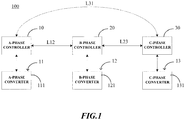
- a three-phase system 100 in a preferable embodiment of the invention comprises three-phase circuits, for example, an A-phase circuit 11, a B-phase circuit 12 and a C-phase circuit 13, wherein each phase circuit may comprise at least one power conversion cell.
- each phase circuit including one power conversion cell as an example, that is, the A-phase circuit 11 has one A-phase converter 111, the B-phase circuit 12 has one B-phase converter 121, and the C-phase circuit 13 has one C-phase converter 131.
- each phase circuit also can include a plurality of power conversion cells, but the invention is not limited thereto.
- the three-phase system 100 of the invention further comprises at least three phase controllers for correspondingly controlling each phase circuit, respectively.
- the A-phase circuit 11, the B-phase circuit 12 and the C-phase circuit 13 are correspondingly controlled by an A-phase controller 10, a B-phase controller 20 and a C-phase controller 30, respectively.
- each of the phase controllers 10, 20 and 30 includes a communication interface through which these phase controllers 10, 20 and 30 are in communications connection with each other.
- the A-phase controller 10 and the B-phase controller 20 may perform communication and coordination therebetween via a communication link L12 formed by communication connection of the communication interface
- the B-phase controller 20 and the C-phase controller 30 may perform communication and coordination therebetween via a communication link L23 formed by communication connection of the communication interface
- the C-phase controller 30 and the A-phase controller 10 may perform communication and coordination therebetween via a communication link L31 formed by communication connection of the communication interface.
- the phase controller of each phase circuit may receive signals sent from the phase controllers of other two phase circuits through the communication interface, thereby regulating the voltage of the bridge arm of the power conversion cell in the corresponding phase circuit.
- the phase controller of each phase circuit may receive active power signals sent from the phase controllers of other two phase circuits, and regulates the voltage of the bridge arm of the power conversion cell in the corresponding phase circuit according to the active power signal of each phase circuit and current phase signal or voltage phase signal of the corresponding phase circuit.
- the three-phase system of the invention performs distributed control by utilizing three-phase completely decentralized control with communication coordinated. That is, each of the phase converters is controlled by each phase controller, respectively, while control of each phase uses communication coordination, through which three-phase power grid currents are balanced, and three-phase DC voltages are stabilized.
- the three-phase distributed control can be used. Therefore, hereinafter referring to FIGS. 2 to 7 , the specific contents of the invention are introduced respectively taking the delta-connection three-phase system and the Y-connection three-phase system for example.
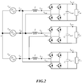
- FIG. 2 illustrates a circuit of a typical combined type delta-connection three-phase system according to the invention.
- the delta-connection three-phase system is divided into AB, BC and CA phases, respectively, and each phase is a H-bridge rectifier circuit.
- v gA , v gB and v gC are three-phase power grid voltages
- i gA , i gB and i gC are three-phase power grid currents
- i CA are currents of three-phase converters
- v bAB , v bBC and v bCA are voltages of bridge arms of the three-phase converters
- v dcAB , v dcBC and v dcCA are three-phase DC voltages
- P AB , P BC and P CA are three-phase load powers.
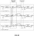
- FIG. 3A illustrates a first preferable embodiment (a reactive current injection method) of a distributed control method of the delta-connection three-phase system according to the invention.
- each phase has a DC voltage loop and a current loop itself.
- v dcrAB is a DC voltage reference of AB phase
- v dcAB is a DC voltage feedback of AB phase, and both of which are calculated to obtain an input of a DC voltage loop controller.
- the DC voltage loop controller may be a proportional integral controller.
- Output of the DC voltage loop controller generates active current reference of the corresponding phase, and i drAB is a d-axis current reference of AB phase, i.e., an active current reference. Meanwhile, the active current reference of the corresponding phase is sent to other two phases for generating reactive current reference.
- i AB and i rAB are calculated to obtain an input of a current loop controller, and for example, the current loop controller may be a proportional resonant controller.
- v gAB v gA - v gB is a power grid voltage of AB phase, which serves as a feedforward to eliminate influence of variation of the power grid voltage on current.
- v gAB and the output of the current loop controller are calculated to generate a modulation voltage reference v rAB of AB phase.
- Other two phases generate v rBC and v rCA using the same method, respectively.
- the modulation voltage references of three phases are subsequent modulated to output bridge arm voltages respectively.
- each of the phase controllers in the delta-connection three-phase system may comprise: a DC voltage loop controller for receiving DC voltage reference and DC voltage feedback of the corresponding phase circuit, and outputting active current reference of the corresponding phase circuit; a three-phase current balancing module for receiving reactive current reference of a power grid and active current references of other two phase circuits sent from the phase controllers of other two phase circuits, and outputting reactive current reference of the corresponding phase circuit; an AC current reference generation module for generating AC current reference of the corresponding phase circuit according to the active current reference of the corresponding phase circuit, the reactive current reference of the corresponding phase circuit and the voltage phase signal of the corresponding phase circuit; and a current loop controller for receiving the AC current reference of the corresponding phase circuit and current feedback of the corresponding phase circuit, and outputting modulation voltage reference of the corresponding phase circuit; wherein the modulation voltage references of the three-phase circuits are modulated to output bridge arm voltage reference of each phase circuit, respectively, and the bridge
- FIG. 3B illustrates a second preferable embodiment (a zero-sequence current injection method) of a distributed control method of the delta-connection three-phase system, which differs from the reactive current injection method shown in FIG. 3A in the implementation of coordination portion.
- the method of obtaining active current references of the three phases is the same as that in the first preferable embodiment, and the details are not described here.
- i r 0 2 3 i drAB cos ⁇ AB + i drBC cos ⁇ BC + i drCA cos ⁇ CA , wherein i drAB is a output of the DC voltage loop of AB phase, and is an active current reference of AB phase that reflects active power signal of AB phase, ⁇ AB is an phase angle of the power grid voltage of AB phase that reflects power grid voltage phase signal of AB phase, and meanings of variables corresponding to subscripts BC and CA are similar with that of the AB phase. Since the zero-sequence current circulates among the three phases, and does not flow into the power grid, the zero-sequence current does not have influence on balance of the three-phase power grid currents.
- each of the phase controllers in the delta-connection three-phase system may comprise: a DC voltage loop controller for receiving DC voltage reference and DC voltage feedback of the corresponding phase circuit, and outputting active current reference of the corresponding phase circuit; a three-phase current balancing module for receiving the active current reference of the corresponding phase circuit and active current references of other two phase circuits sent by the phase controllers of other two phase circuits, and outputting balance current reference of the corresponding phase circuit; an AC current reference generation module for generating AC current reference of the corresponding phase circuit according to a reactive current reference of a power grid, the balance current reference of the corresponding phase circuit, and the voltage phase signal of the corresponding phase circuit; a DC voltage balancing module for generating AC current reference of the corresponding phase circuit according to the AC current reference of the corresponding phase circuit and a zero-sequence current; and a current loop controller for receiving the AC current reference of the corresponding phase circuit and current feedback of the corresponding phase circuit, and out
- each of the phase controllers generates active power signal (i.e. active current reference in this embodiment) reflecting active power of the corresponding phase circuit according to voltage signal (i.e. DC voltage reference and DC voltage feedback in this embodiment) of the corresponding phase circuit, respectively, receives the active power signals of other two phase circuits, and generates the zero-sequence current according to the active power signal of each phase circuits and the voltage phase signal of each phase circuits.
- active power signal i.e. active current reference in this embodiment
- voltage signal i.e. DC voltage reference and DC voltage feedback in this embodiment
- Control effects of the two embodiments in FIGS. 3A and 3B are equivalent, and both can balance three-phase current, and stabilize three-phase DC voltages.
- FIG. 4 illustrates a general block diagram of a distributed control method of the delta-connection three-phase system according to the invention, wherein i drAB , i drCA , i drBC and i r0 are amounts need for communication coordination.
- the block diagram generalizes the foregoing two embodiments, and each of the phase controllers in the delta-connection three-phase system comprises a DC voltage loop controller, a three-phase current balancing module, an AC current reference generation module, a DC voltage balancing module and a current loop controller.
- FIG. 5 illustrates a circuit of the Y-connection three-phase system according to the invention.
- v gA , v gB and v gC are three-phase power grid voltages
- i A , i B and i C are three-phase power grid currents, and are also currents of three-phase converters
- v bA , v bB and v bC are bridge arm voltages of the three-phase converters
- v dcA , v dcB and v dcC are three-phase DC voltages
- P A , P B and P C are three-phase load powers.
- FIG. 6 illustrates a block diagram of distributed control of the Y-connection three-phase system according to the invention.
- each phase has a DC voltage loop and a current loop itself.
- V dcrA is a DC voltage reference of A phase
- v dcA is a DC voltage feedback of A phase
- both are calculated to obtain an inputs of the DC voltage loop controller.
- the DC voltage loop controller may be a proportional integral controller. Output of the DC voltage loop controller generates an active current reference i drA of the corresponding phase.
- the function of averaging the active current references of the three phases is to balance three-phase currents.
- i A is a current feedback of the A phase converter.
- the AC current reference of the A phase and the current feedback of the A phase converter are calculated to obtain an input of a current loop controller, and for example, the current loop controller may be a proportional resonant controller.
- v gA is a power grid voltage of A phase, and serves as a feedforward to be injected into output of the current loop controller to eliminate influence of variation of the power grid voltage on current. In addition, a zero-sequence voltage is injected to balance three-phase DC voltages.
- v b0 k 0 i A i drA + i B i drB + i C i drC .
- i A , i B and i C are respectively current feedbacks of the three phases that reflect current phase signal of each phase
- i drA , i drB and i drC are outputs of the DC voltage loop controller of each phase
- ko is a proportional coefficient, such as a constant or a value according to a current amplitude.
- k 0 V gM i A 2 + i B 2 + i C 2 , wherein V gM is a peak value of the power grid voltage.
- the injected zero-sequence voltage cause imbalance of the three-phase bridge arm voltages, and imbalance of powers absorbed by bridge arms to deal with imbalance of load powers at DC sides, thereby keep stabilization of the DC voltages. Since the injected zero-sequence voltage in the Y-connection three-phase system dose not generate a zero-sequence current, thereby the balance of three-phase current is not influenced.
- the output of the current loop controller is injected into the A-phase power grid voltage to generate an output voltage reference v rAP .
- the output voltage reference v rAP and the zero-sequence voltage v b0 are added to finally generate modulation voltage references v rA .
- v rB and v rC can also be generated in the same way.
- bridge arm voltages are outputted after modulating v rA , v rB and v rC .
- FIG. 7 illustrates a general block diagram of a distributed control method of the Y-connection three-phase system according to the invention, wherein i drA , i drB , i drB and v b0 are values with communication coordination.
- the Y-connection three-phase system comprises a DC voltage loop controller, a three-phase current balancing module, an AC current reference generation module, a current loop controller and a DC voltage balancing module. Difference from a coordination cell of the delta-connection three-phase system is that a zero-sequence voltage of the Y-connection three-phase system is added to output of the current loop.
- each of the phase controllers in the Y-connection three-phase system of the invention may comprise: a DC voltage loop controller for receiving DC voltage reference and DC voltage feedback of the corresponding phase circuit, and outputting active current reference of the corresponding phase circuit; a three-phase current balancing module for receiving the active current reference of the corresponding phase circuit and active current references of other two phase circuits sent from the phase controllers of other two phase circuits, and outputting balance current references of the phase circuit; an AC current reference generation module for generating AC current reference of the corresponding phase circuit according to a reactive current reference of a power grid, the balance current reference of the corresponding phase circuit, and the voltage phase signal of the corresponding phase circuit; a current loop controller for receiving the AC current reference of the corresponding phase circuit and current feedback of the corresponding phase circuit, and generating output voltage reference of the corresponding phase circuit; and a DC voltage balancing module for generating modulation voltage reference of the corresponding phase circuit according to the output voltage reference of the corresponding phase circuit and a zero-sequence
- each of the phase controllers generates active power signal reflecting active power of the corresponding phase circuit according to voltage signal reflecting the voltage of corresponding phase circuit, respectively, and receives the active power signals of other two phase circuits, and generates the zero-sequence voltage according to the active power signal reflecting the active power of each phase circuits and the current phase signal of each phase circuits.
- each phase circuit has only one converter
- the foregoing disclosures give embodiments of distributed control.
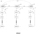
- each phase circuit 11, 12 and 13 includes a plurality of power conversion cells 111, 121 and 121, i.e., formed by connecting a plurality of converter cells CELL 1 to CELL N in series, for example, a three-phase cascade H-bridge system
- an implementation architecture of the controller shown in FIG. 8 may be used. Accordingly, DC voltage feedbacks in the respective phase controllers 10, 20 and 30 shall be a sum of DC voltages of all converter cells of the respective phase circuits.
- the plurality of converter cells (i.e., power conversion cells) of each phase circuit and the corresponding phase controllers are in serial communications connection, and form a loop network.
- the plurality of converter cells in each phase circuit may be loop communication, and the respective controllers also may be loop communication.
- communication among the plurality of power conversion cells of each phase circuit also may be bus communication or star communication, and communication among the phase circuits also may be bus communication or star communication, but the invention is not limited thereto.
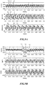
- FIG. 9A illustrates effects of distributed control method of the delta-connection three-phase system according to the invention, wherein a top channel Vdc is three-phase DC voltages, a middle channel I gline is three-phase power grid currents, and a bottom channel I phase is bridge arm currents of three-phase converters.
- L1, L2 and L3 represent AB, BC and CA phases, respectively.
- Waveforms in FIG. 9A are obtained under operating conditions of imbalance of loads at three-phase DC sides, and load currents at the DC sides of the AB, BC and CA phases are 3A, 1A and 5A, respectively. Before 0.2s, the three phases are completely independent distributed controlled.
- the three-phase power grid currents and the power grid currents of the three-phase converters are unbalanced, because of differences of three-phase load powers.
- An average value of the three-phase DC voltages is balanced, and amplitudes of double frequency fluctuation of the three-phase DC voltages are different.
- distributed control provided by the invention is used.
- the three-phase power grid currents are balanced, and the three-phase DC voltages are also balanced through coordination control.
- bridge arm currents of the three-phase converter are still unbalanced, only if the three-phase power grid currents are balanced, it satisfys requirements for the power grid, so the method provided by the invention can satisfy the requirements for the power grid.
- FIG. 9B illustrates distributed control effects of the Y-connection three-phase system according to the invention, wherein a top channel Vdc is three-phase DC voltages, a middle channel I g is three-phase power grid currents, and a bottom channel V b is bridge arm voltages of three-phase converters and a zero-sequence voltage.
- L1, L2 and L3 represent AB, BC and CA phases, respectively, and L4 represents the zero-sequence voltage.
- an operating condition is set that DC loads are balance, and stabilization is also possible without adding the control of the invention. However, after 0.18s, the operating condition is set that the loads at three-phase DC sides are imbalance, and currents at the DC sides are 3A, 2A and 4A, respectively.
- the three-phase DC voltages cannot be stabilized. After 0.2s, distributed control provided by the invention is used, and a zero-sequence voltage is injected through coordination. As can be seen, the bridge arm voltages of the three phases are no longer balanced, and work with the three-phase balanced power grid currents to generate unbalanced bridge arm powers, so as to deal with different load powers at the DC sides, such that the three-phase DC voltages are stabilized and balanced, and the three-phase power grid currents are also balanced.
- the three-phase DC voltages of the invention are controlled, respectively, when references of the three-phase DC voltages are different, it is also possible to stably operate, which is difficult for centralized control, because there is only one centralized DC voltage loop, and it is difficult to give three different DC voltage references, respectively.
- Distributed control of the three-phase system of the invention is operated in an operating condition where the three-phase DC voltage references are set to be different. For example, three-phase battery voltages in photovoltaic application are different, and effects are shown in FIG. 9C .
- the three-phase DC voltages may be operated in 1680V, 1580V and 1480V, respectively.
- the three-phase system may be a delta-connection three-phase system shown in FIG. 2 .
- the active power signals of each phase circuit may be active current references i drAB , i drBC and i drCA of each phase circuit, and the phase signals of each phase circuit may be voltage phase signals ⁇ AB , ⁇ BC and ⁇ CA of each phase circuit.
- Each of the phase controllers may generate a zero-sequence current i r0 according to the active current references i drAB , i drBC and i drCA reflecting the active power signal of the respective phase circuits and the voltage phase signals ⁇ AB , ⁇ BC and ⁇ CA reflecting voltage phases of the respective phase circuits.
- the active current references i drAB , i drBC and i drCA reflecting the active power signal of the respective phase circuits are the active current reference reflecting the active power of the phase circuit and active current references reflecting active powers of other two phase circuits received by each of the phase controllers.
- each of the phase controllers in the delta-connection three-phase system may comprise: a DC voltage loop controller for receiving DC voltage reference VdcrAB, v dcrBC , v dcrCA and DC voltage feedback v dcAB , v dcBC , v dcCA of the corresponding phase circuit, and outputting active current reference i drAB , i drBC , i drCA of the corresponding phase circuit; a three-phase current balancing module for receiving the active current reference of the corresponding phase circuit and active current references of other two phase circuits sent from the phase controllers of other two phase circuits, and outputting balance current reference i drComAB , i drComBC , i drComCA of the corresponding phase circuit; an AC current reference generation module for generating AC current reference i rABP , i rBCP , i rCAP of the corresponding phase circuit according to a reactive current reference I qr
- the three-phase system may be a Y-connection three-phase system shown in FIG. 5 .
- the active power signals of each phase circuit may be active current references i drA , i drB and i drC of each phase circuit, and the phase signals of each phase circuit may be phase signals of three phase current feedback i A , i B and i C respectively.
- Each of the phase controllers may receive active current references reflecting active powers of other two phase circuits, and generate a zero-sequence voltage v b0 according to the active current references i drA , i drB , i drC reflecting the active power signal of the respective phase circuits and the current phase signals i A , i B , ic reflecting current phases of the respective phase circuits.
- each of the phase controllers in the Y-connection three-phase system may comprise: a DC voltage loop controller for receiving DC voltage reference v dcrA , v dcrB , v dcrC and DC voltage feedback v dc , v dc , v dc of the corresponding phase circuit, and outputting active current reference i drA , i drB , i drC of the corresponding phase circuit; a three-phase current balancing module for receiving the active current reference of the corresponding phase circuit and active current references of other two phase circuits sent from the phase controllers of other two phase circuits, and outputting balance current reference idrComA, i drComB , i drComC of the corresponding phase circuit; an AC current reference generation module for generating AC current reference i rA , i rB , i rC of the corresponding phase circuit according to a reactive current reference I qr of a
- the invention provides a distributed control method of a three-phase system, wherein the three-phase system comprises: three-phase circuits, each phase circuit of the three-phase circuit including at least one power conversion cell; and at least three phase controllers for controlling each phase circuit, respectively, each of the phase controllers including a communication interface through which the at least three phase controllers are in communications connection with each other, wherein the distributed control method comprises:
- the three-phase system may be a delta-connection three-phase system, the active power signal of each phase circuit may be active current reference of each phase circuit, and the phase signal of each phase circuit may be voltage phase signal of each phase circuit.
- Each of the phase controllers receives active current references reflecting active powers of other two phase circuits.
- Each of the phase controllers may generate a zero-sequence current according to the active current reference reflecting active power of each phase circuits and the voltage phase signal reflecting voltage phase of each phase circuits.
- each of the phase controllers in the delta-connection three-phase system may comprise: a DC voltage loop controller for receiving DC voltage reference and DC voltage feedback of the corresponding phase circuit, and outputting active current reference of the corresponding phase circuit; a three-phase current balancing module for receiving the active current reference of the corresponding phase circuit and active current references of other two phase circuits sent from the phase controllers of other two phase circuits, and outputting balance current reference of the corresponding phase circuit; an AC current reference generation module for generating AC current reference of the corresponding phase circuit according to a reactive current reference of a power grid, the balance current reference of the corresponding phase circuit, and the voltage phase signal of the corresponding phase circuit; a DC voltage balancing module for generating AC current reference of the corresponding phase circuit according to the AC current reference of the corresponding phase circuit and a zero-sequence current; and a current loop controller for receiving the AC current reference of the corresponding phase circuit and current feedback of the corresponding phase circuit, and outputting modulation voltage reference of the corresponding phase circuit;
- the three-phase system also may be a Y-connection three-phase system, the active power signal of each phase circuit may be active current reference of each phase circuit, and the phase signal of each phase circuit may be current phase signal of each phase circuit.
- Each of the phase controllers receives active current references reflecting active powers of other two phase circuits.
- Each of the phase controllers may generate a zero-sequence voltage according to the active current references reflecting active power of each phase circuits and the current phase signals reflecting current phases of each phase circuits.
- each of the phase controllers in the Y-connection three-phase system may comprise: a DC voltage loop controller for receiving DC voltage reference and DC voltage feedback of the corresponding phase circuit, and outputting active current reference of the corresponding phase circuit; a three-phase current balancing module for receiving the active current reference of the corresponding phase circuit and active current references of other two phase circuits sent from the phase controllers of other two phase circuits, and outputting balance current reference of the corresponding phase circuit; an AC current reference generation module for generating AC current reference of the corresponding phase circuit according to a reactive current reference of a power grid, the balance current reference of the phase circuit, and the voltage phase signals of the phase circuit; a current loop controller for receiving the AC current reference of the corresponding phase circuit and current feedback of the corresponding phase circuit, and outputting output voltage reference of the corresponding phase circuit; and a DC voltage balancing module for generating modulation voltage reference of the corresponding phase circuit according to the output voltage reference of the corresponding phase circuit and a zero-sequence voltage; wherein the modulation
- the three-phase system and the distributed control method thereof in the invention solve problems of balance of three-phase currents and stabilization of three-phase DC voltages through coordination among the three phases.
- single point failure risk of the controller is reduced, and the three phases can be independently and individually controlled to improve control flexibility
Landscapes
- Engineering & Computer Science (AREA)
- Power Engineering (AREA)
- Inverter Devices (AREA)
- Control Of Electrical Variables (AREA)
- Supply And Distribution Of Alternating Current (AREA)
Abstract
Description
- The invention relates to the technical field of power electronics, and particularly to a three-phase system and a distributed control method thereof.
- Three-phase combined type converter refers to a three-phase converter formed of a combination of three single-phase systems. Three-phase Cascade H-Bridge (CHB) is a typical three-phase combined type converter, and is a structure widely applied in medium and high voltage power inverters. The CHB topology may be applied to products, such as, Static Var Generator (SVG), Solid State Transformer (SST), and medium and high voltage storage inverters.
- The three-phase CHB has two connections, i.e., Y-connection and delta-connection. The key problem of controlling the three-phase combined type converter is how to ensure stabilization of three-phase DC voltages (i.e., DC-link voltages), and balance of three-phase power grid currents when loads at three-phase DC sides are unbalanced.
- Currently, a centralized control manner is generally utilized, i.e., feeding back and controlling a three-phase average DC voltage through a centralized controller, and a voltage balance control is added such that a DC voltage of each phase approaches the three-phase average voltage. Generally, a zero-sequence injection method is used to balance the three-phase DC voltages. As for a delta-connection system, a zero-sequence current injection method is used, and as for a Y-connection system, a zero-sequence voltage injection method is used.
- However, the current centralized control manner has a low reliablity, and once the centralized controller has failure, or one phase circuit has failure, the entire three-phase system stops working, and cannot be stably operated.
- An object of the invention is to provide a three-phase system and a distributed control method thereof, which can solve one or more deficiencies in the prior art.
- To realize the above object, the invention provides a three-phase system, comprising: three-phase circuit, each phase circuit of the three-phase circuit including at least one power conversion cell; and at least three phase controllers for controlling each phase circuit, respectively, each of the phase controllers including a communication interface through which the at least three phase controllers are in communications connection with each other; wherein the phase controller of each phase circuit is configured for regulating bridge arm voltage of the at least one power conversion cell in the corresponding phase circuit by receiving signals sent from the phase controllers of other two phase circuits through the communication interface.
- To realize the above object, the invention further provides a three-phase system, comprising: three-phase circuit, each phase circuit of the three-phase circuit including at least one power conversion cell; and at least three phase controllers for controlling each phase circuit, respectively, wherein each of the phase controllers generates active power signal (XA, XB and XC) reflecting active power of the corresponding phase circuit according to voltage signal reflecting the corresponding phase circuit, respectively; each of the phase controllers also receives active power signals reflecting active powers of other two phase circuits, and generate zero-sequence component according to the active power signals (XA, XB and XC) reflecting active power of each phase circuit and phase signals (YA, YB and YC) reflecting current phase or voltage phase of each phase circuits, wherein, the zero-sequence component = (XA×YA+XB×YB+XC×YC) × K0, where K0 is a proportional coefficient; each of the phase controllers further regulates bridge arm voltage of each power conversion cell in the corresponding phase circuit according to the zero-sequence component correspondingly.
- To realize the above object, the invention further provides distributed control method of a three-phase system, wherein the three-phase system comprises: three-phase circuits, each phase circuit of the three-phase circuit including at least one power conversion cell; and at least three phase controllers for controlling each phase circuit, respectively, each of the phase controllers including a communication interface through which the at least three phase controllers are in communications connection with each other; wherein the distributed control method comprises:
- when loads at DC sides of the three-phase system are unbalanced,
- generating, by each of the phase controllers, active power signal (XA, XB, XC) reflecting active power of the corresponding phase circuit according to voltage signal of the corresponding phase circuit, respectively;
- receiving, by each of the phase controllers, active power signals reflecting active powers of other two phase circuits, and generating zero-sequence components according to the active power signals (XA, XB and XC) reflecting active powers of each phase circuits and phase signals (YA, YB and YC) reflecting current phases or voltage phases of each phase circuits, wherein,
- the zero-sequence components = (XA×YA+XB×YB+XC×YC) × K0, where K0 is a proportional coefficient;
- regulating, by each of the phase controllers, bridge arm voltages of the respective power conversion cells in the corresponding phase circuit according to the zero-sequence components correspondingly.
- The three-phase system and the distributed control method thereof in the invention solve problems of balance of three-phase current and stabilization of three-phase DC voltages through coordination among the three phases. As compared to the centralized control manner, single point failure risk of the controller is reduced, and the three phases can be independently and individually controlled to improve control flexibility.
- The additional aspects and advantages of the invention are partially explained in the below description, and partially becoming apparent from the description, or can be obtained through practice of the invention.
- The exemplary embodiments will be described in detail with reference to the accompanying drawings, through which the above and other features and advantages of the disclosure will become more apparent.
-
FIG. 1 is a structural diagram of a three-phase system according to a preferable embodiment of the invention. -
FIG. 2 is a schematic diagram illustrating a circuit of a delta-connection three-phase system according to the invention. -
FIG. 3A is a schematic diagram illustrating a first preferable embodiment of a distributed control method of the delta-connection three-phase system according to the invention. -
FIG. 3B is a schematic diagram illustrating a second preferable embodiment of a distributed control method of the delta-connection three-phase system according to the invention. -
FIG. 4 illustrates a general block diagram of a distributed control method of the delta-connection three-phase system according to the invention. -
FIG. 5 is a schematic diagram illustrating a circuit of a Y-connection three-phase system according to the invention. -
FIG. 6 is a schematic diagram illustrating a distributed control method of the Y-connection three-phase system according to the invention. -
FIG. 7 illustrates a general block diagram of a distributed control method of the Y-connection three-phase system according to the invention. -
FIG. 8 is a structural diagram of a three-phase system according to other preferable embodiment of the invention, wherein each phase circuit comprises a plurality of power conversion cells connected in series. -
FIG. 9A illustrates effects of the delta-connection three-phase system in the distributed control according to the invention. -
FIG. 9B illustrates effects of the Y-connection three-phase system in distributed control according to the invention. -
FIG. 9C illustrates effects when three-phase DC voltages are stably operated at different values in the distributed control method of the invention. - The exemplary embodiments will now be described more fully with reference to the accompanying drawings. However, the exemplary embodiments can be implemented in various forms and shall not be understood as being limited to the embodiments set forth herein; on the contrary, these embodiments are provided so that this invention will be thorough and complete, and the conception of exemplary embodiments will be fully conveyed to those skilled in the art. In the drawings, the same reference sign denotes the same or similar structure, so their detailed description will be omitted.
- When factors/components/the like described and/or illustrated here are introduced, the phrases "one", "a(an)", "the", "said" and "at least one" refer to one or more factors/components/the like. The terms "include", "comprise" and "have" refer to an open and included meaning, and refer to additional factors/components/the like, in addition to the listed factors/components/the like. The embodiments may use relative phrases, such as, "upper" or "lower" to describe a relative relation of one signed component over other component. It shall be understood that if the signed device reverses to turn upside down, the described component on an "upper" side will become a component on a "lower" side. In addition, the terms "first", "second" and the like in the claims are only used as signs, instead of numeral limitations to obj ects.
- As shown in
FIG. 1 , a three-phase system 100 in a preferable embodiment of the invention comprises three-phase circuits, for example, anA-phase circuit 11, a B-phase circuit 12 and a C-phase circuit 13, wherein each phase circuit may comprise at least one power conversion cell. In the embodiment ofFIG. 1 , taking each phase circuit including one power conversion cell as an example, that is, theA-phase circuit 11 has oneA-phase converter 111, the B-phase circuit 12 has one B-phase converter 121, and the C-phase circuit 13 has one C-phase converter 131. However, it shall be understood that in other embodiments, each phase circuit also can include a plurality of power conversion cells, but the invention is not limited thereto. - The three-
phase system 100 of the invention further comprises at least three phase controllers for correspondingly controlling each phase circuit, respectively. For example, theA-phase circuit 11, the B-phase circuit 12 and the C-phase circuit 13 are correspondingly controlled by anA-phase controller 10, a B-phase controller 20 and a C-phase controller 30, respectively. In the invention, each of thephase controllers phase controllers A-phase controller 10 and the B-phase controller 20 may perform communication and coordination therebetween via a communication link L12 formed by communication connection of the communication interface, the B-phase controller 20 and the C-phase controller 30 may perform communication and coordination therebetween via a communication link L23 formed by communication connection of the communication interface, and the C-phase controller 30 and theA-phase controller 10 may perform communication and coordination therebetween via a communication link L31 formed by communication connection of the communication interface. - In the invention, the phase controller of each phase circuit may receive signals sent from the phase controllers of other two phase circuits through the communication interface, thereby regulating the voltage of the bridge arm of the power conversion cell in the corresponding phase circuit. For example, the phase controller of each phase circuit may receive active power signals sent from the phase controllers of other two phase circuits, and regulates the voltage of the bridge arm of the power conversion cell in the corresponding phase circuit according to the active power signal of each phase circuit and current phase signal or voltage phase signal of the corresponding phase circuit.
- The three-phase system of the invention performs distributed control by utilizing three-phase completely decentralized control with communication coordinated. That is, each of the phase converters is controlled by each phase controller, respectively, while control of each phase uses communication coordination, through which three-phase power grid currents are balanced, and three-phase DC voltages are stabilized.
- In the invention, as for the delta-connection three-phase system and the Y-connection three-phase system, the three-phase distributed control can be used. Therefore, hereinafter referring to
FIGS. 2 to 7 , the specific contents of the invention are introduced respectively taking the delta-connection three-phase system and the Y-connection three-phase system for example. -
FIG. 2 illustrates a circuit of a typical combined type delta-connection three-phase system according to the invention. The delta-connection three-phase system is divided into AB, BC and CA phases, respectively, and each phase is a H-bridge rectifier circuit. InFIG. 2 , vgA, vgB and vgC are three-phase power grid voltages, igA, igB and igC are three-phase power grid currents, iAB, iBC, iCA are currents of three-phase converters, vbAB, vbBC and vbCA are voltages of bridge arms of the three-phase converters, vdcAB, vdcBC and vdcCA are three-phase DC voltages, and PAB, PBC and PCA are three-phase load powers. -
FIG. 3A illustrates a first preferable embodiment (a reactive current injection method) of a distributed control method of the delta-connection three-phase system according to the invention. In this embodiment, each phase has a DC voltage loop and a current loop itself. Hereinafter taking the AB phase as an example, detailed explanations are made, and other two phases are similar. vdcrAB is a DC voltage reference of AB phase, vdcAB is a DC voltage feedback of AB phase, and both of which are calculated to obtain an input of a DC voltage loop controller. For example, the DC voltage loop controller may be a proportional integral controller. Output of the DC voltage loop controller generates active current reference of the corresponding phase, and idrAB is a d-axis current reference of AB phase, i.e., an active current reference. Meanwhile, the active current reference of the corresponding phase is sent to other two phases for generating reactive current reference. The reactive current reference of the corresponding phase is
- As can be seen, in the first preferable embodiment of
FIG. 3A , each of the phase controllers in the delta-connection three-phase system may comprise: a DC voltage loop controller for receiving DC voltage reference and DC voltage feedback of the corresponding phase circuit, and outputting active current reference of the corresponding phase circuit; a three-phase current balancing module for receiving reactive current reference of a power grid and active current references of other two phase circuits sent from the phase controllers of other two phase circuits, and outputting reactive current reference of the corresponding phase circuit; an AC current reference generation module for generating AC current reference of the corresponding phase circuit according to the active current reference of the corresponding phase circuit, the reactive current reference of the corresponding phase circuit and the voltage phase signal of the corresponding phase circuit; and a current loop controller for receiving the AC current reference of the corresponding phase circuit and current feedback of the corresponding phase circuit, and outputting modulation voltage reference of the corresponding phase circuit; wherein the modulation voltage references of the three-phase circuits are modulated to output bridge arm voltage reference of each phase circuit, respectively, and the bridge arm voltage of each phase circuit may be regulated according to the bridge arm voltage reference.FIG. 3B illustrates a second preferable embodiment (a zero-sequence current injection method) of a distributed control method of the delta-connection three-phase system, which differs from the reactive current injection method shown inFIG. 3A in the implementation of coordination portion. The method of obtaining active current references of the three phases is the same as that in the first preferable embodiment, and the details are not described here. The active current references of the three phases are averaged to obtain a balance current reference of the phase, i.e.,


- As can be seen, in the second embodiment shown in
FIG. 3B , each of the phase controllers in the delta-connection three-phase system may comprise: a DC voltage loop controller for receiving DC voltage reference and DC voltage feedback of the corresponding phase circuit, and outputting active current reference of the corresponding phase circuit; a three-phase current balancing module for receiving the active current reference of the corresponding phase circuit and active current references of other two phase circuits sent by the phase controllers of other two phase circuits, and outputting balance current reference of the corresponding phase circuit; an AC current reference generation module for generating AC current reference of the corresponding phase circuit according to a reactive current reference of a power grid, the balance current reference of the corresponding phase circuit, and the voltage phase signal of the corresponding phase circuit; a DC voltage balancing module for generating AC current reference of the corresponding phase circuit according to the AC current reference of the corresponding phase circuit and a zero-sequence current; and a current loop controller for receiving the AC current reference of the corresponding phase circuit and current feedback of the corresponding phase circuit, and outputting modulation voltage reference of the corresponding phase circuit; wherein the modulation voltage references of the three-phase circuits are modulated to output bridge arm voltage reference of each phase circuit, respectively, and the bridge arm voltage of each phase circuit may be regulated according to the bridge arm voltage references. - Moreover, in this embodiment, each of the phase controllers generates active power signal (i.e. active current reference in this embodiment) reflecting active power of the corresponding phase circuit according to voltage signal (i.e. DC voltage reference and DC voltage feedback in this embodiment) of the corresponding phase circuit, respectively, receives the active power signals of other two phase circuits, and generates the zero-sequence current according to the active power signal of each phase circuits and the voltage phase signal of each phase circuits.
- Control effects of the two embodiments in
FIGS. 3A and3B are equivalent, and both can balance three-phase current, and stabilize three-phase DC voltages. -
FIG. 4 illustrates a general block diagram of a distributed control method of the delta-connection three-phase system according to the invention, wherein idrAB, idrCA, idrBC and ir0 are amounts need for communication coordination. The block diagram generalizes the foregoing two embodiments, and each of the phase controllers in the delta-connection three-phase system comprises a DC voltage loop controller, a three-phase current balancing module, an AC current reference generation module, a DC voltage balancing module and a current loop controller. -
FIG. 5 illustrates a circuit of the Y-connection three-phase system according to the invention. InFIG. 5 , vgA, vgB and vgC are three-phase power grid voltages, iA, iB and iC are three-phase power grid currents, and are also currents of three-phase converters, vbA, vbB and vbC are bridge arm voltages of the three-phase converters, vdcA, vdcB and vdcC are three-phase DC voltages, and PA, PB and PC are three-phase load powers. -
FIG. 6 illustrates a block diagram of distributed control of the Y-connection three-phase system according to the invention. In this embodiment, each phase has a DC voltage loop and a current loop itself. Hereinafter taking the A phase as an example, detailed explanations are made, and other two phases are similar. VdcrA is a DC voltage reference of A phase, vdcA is a DC voltage feedback of A phase, and both are calculated to obtain an inputs of the DC voltage loop controller. For example, the DC voltage loop controller may be a proportional integral controller. Output of the DC voltage loop controller generates an active current reference idrA of the corresponding phase. Then, active current references idrB and idrC of other two phases are received to generate a balance current reference idrcomA =


-
FIG. 7 illustrates a general block diagram of a distributed control method of the Y-connection three-phase system according to the invention, wherein idrA, idrB, idrB and vb0 are values with communication coordination. The Y-connection three-phase system comprises a DC voltage loop controller, a three-phase current balancing module, an AC current reference generation module, a current loop controller and a DC voltage balancing module. Difference from a coordination cell of the delta-connection three-phase system is that a zero-sequence voltage of the Y-connection three-phase system is added to output of the current loop. - As can be seen, each of the phase controllers in the Y-connection three-phase system of the invention may comprise: a DC voltage loop controller for receiving DC voltage reference and DC voltage feedback of the corresponding phase circuit, and outputting active current reference of the corresponding phase circuit; a three-phase current balancing module for receiving the active current reference of the corresponding phase circuit and active current references of other two phase circuits sent from the phase controllers of other two phase circuits, and outputting balance current references of the phase circuit; an AC current reference generation module for generating AC current reference of the corresponding phase circuit according to a reactive current reference of a power grid, the balance current reference of the corresponding phase circuit, and the voltage phase signal of the corresponding phase circuit; a current loop controller for receiving the AC current reference of the corresponding phase circuit and current feedback of the corresponding phase circuit, and generating output voltage reference of the corresponding phase circuit; and a DC voltage balancing module for generating modulation voltage reference of the corresponding phase circuit according to the output voltage reference of the corresponding phase circuit and a zero-sequence voltage; wherein the modulation voltage references of the three-phase circuits are modulated to output bridge arm voltage reference of each phase circuit, respectively, and the bridge arm voltage of each phase circuit is regulated according to the bridge arm voltage references.
- In this embodiment, each of the phase controllers generates active power signal reflecting active power of the corresponding phase circuit according to voltage signal reflecting the voltage of corresponding phase circuit, respectively, and receives the active power signals of other two phase circuits, and generates the zero-sequence voltage according to the active power signal reflecting the active power of each phase circuits and the current phase signal of each phase circuits.
- With respect to the circumstance that each phase circuit has only one converter, the foregoing disclosures give embodiments of distributed control. However, it shall be understood that as shown in
FIG. 8 , when eachphase circuit power conversion cells converter cells CELL 1 to CELL N in series, for example, a three-phase cascade H-bridge system, an implementation architecture of the controller shown inFIG. 8 may be used. Accordingly, DC voltage feedbacks in therespective phase controllers - For example, each phase circuit may be formed by connecting N
converter cells CELL 1 to CELL N in series, and N is reasonably designed depending on voltage classes of the system and a rated voltage of each converter cell. For example, in a 11KV system, when a DC voltage of each converter cell is 1600V, it is possible to design N=8 or N=9. In the embodiment ofFIG. 8 , the plurality of converter cells (i.e., power conversion cells) of each phase circuit and the corresponding phase controllers are in serial communications connection, and form a loop network. The plurality of converter cells in each phase circuit may be loop communication, and the respective controllers also may be loop communication. Of course, it shall be understood that communication among the plurality of power conversion cells of each phase circuit also may be bus communication or star communication, and communication among the phase circuits also may be bus communication or star communication, but the invention is not limited thereto. - Technical effects of the invention are as follows:
FIG. 9A illustrates effects of distributed control method of the delta-connection three-phase system according to the invention, wherein a top channel Vdc is three-phase DC voltages, a middle channel Igline is three-phase power grid currents, and a bottom channel Iphase is bridge arm currents of three-phase converters. L1, L2 and L3 represent AB, BC and CA phases, respectively. Waveforms inFIG. 9A are obtained under operating conditions of imbalance of loads at three-phase DC sides, and load currents at the DC sides of the AB, BC and CA phases are 3A, 1A and 5A, respectively. Before 0.2s, the three phases are completely independent distributed controlled. As can be seen, the three-phase power grid currents and the power grid currents of the three-phase converters are unbalanced, because of differences of three-phase load powers. An average value of the three-phase DC voltages is balanced, and amplitudes of double frequency fluctuation of the three-phase DC voltages are different. After 0.2s, distributed control provided by the invention is used. The three-phase power grid currents are balanced, and the three-phase DC voltages are also balanced through coordination control. Although bridge arm currents of the three-phase converter are still unbalanced, only if the three-phase power grid currents are balanced, it satisfys requirements for the power grid, so the method provided by the invention can satisfy the requirements for the power grid. -
FIG. 9B illustrates distributed control effects of the Y-connection three-phase system according to the invention, wherein a top channel Vdc is three-phase DC voltages, a middle channel Ig is three-phase power grid currents, and a bottom channel Vb is bridge arm voltages of three-phase converters and a zero-sequence voltage. L1, L2 and L3 represent AB, BC and CA phases, respectively, and L4 represents the zero-sequence voltage. Before 0.18s, an operating condition is set that DC loads are balance, and stabilization is also possible without adding the control of the invention. However, after 0.18s, the operating condition is set that the loads at three-phase DC sides are imbalance, and currents at the DC sides are 3A, 2A and 4A, respectively. As can be seen, the three-phase DC voltages cannot be stabilized. After 0.2s, distributed control provided by the invention is used, and a zero-sequence voltage is injected through coordination. As can be seen, the bridge arm voltages of the three phases are no longer balanced, and work with the three-phase balanced power grid currents to generate unbalanced bridge arm powers, so as to deal with different load powers at the DC sides, such that the three-phase DC voltages are stabilized and balanced, and the three-phase power grid currents are also balanced. - Since the three-phase DC voltages of the invention are controlled, respectively, when references of the three-phase DC voltages are different, it is also possible to stably operate, which is difficult for centralized control, because there is only one centralized DC voltage loop, and it is difficult to give three different DC voltage references, respectively. Distributed control of the three-phase system of the invention is operated in an operating condition where the three-phase DC voltage references are set to be different. For example, three-phase battery voltages in photovoltaic application are different, and effects are shown in
FIG. 9C . The three-phase DC voltages may be operated in 1680V, 1580V and 1480V, respectively. - In addition, the invention further provides a three-phase system, comprising: three-phase circuit, each phase circuit of the three-phase circuit including at least one power conversion cell; and at least three phase controllers for correspondingly controlling each phase circuit, respectively, wherein each of the phase controllers generates active power signal XA, XB and XC reflecting active powers of the corresponding phase circuit according to voltage signal reflecting the voltage of corresponding phase circuit, respectively; each of the phase controllers also receives active power signals reflecting active powers of other two phase circuits, and generate zero-sequence component according to the active power signal XA, XB and XC reflecting active power of each phase circuit and phase signal YA, YB and YC reflecting current phase or voltage phase of each phase circuit, wherein, the zero-sequence component= (XA×YA+XB×YB+XC×YC) × K0, where K0 is a proportional coefficient; each of the phase controllers also regulate bridge arm voltages of the respective power conversion cells in the corresponding phase circuit according to the zero-sequence component correspondingly.
- Preferably, the three-phase system, for example, may be a delta-connection three-phase system shown in
FIG. 2 . As shown inFIG. 4 , the active power signals of each phase circuit may be active current references idrAB, idrBC and idrCA of each phase circuit, and the phase signals of each phase circuit may be voltage phase signals θAB, θBC and θCA of each phase circuit. Each of the phase controllers may generate a zero-sequence current ir0 according to the active current references idrAB, idrBC and idrCA reflecting the active power signal of the respective phase circuits and the voltage phase signals θAB, θBC and θCA reflecting voltage phases of the respective phase circuits. The active current references idrAB, idrBC and idrCA reflecting the active power signal of the respective phase circuits are the active current reference reflecting the active power of the phase circuit and active current references reflecting active powers of other two phase circuits received by each of the phase controllers. - More specifically, each of the phase controllers in the delta-connection three-phase system may comprise: a DC voltage loop controller for receiving DC voltage reference VdcrAB, vdcrBC, vdcrCA and DC voltage feedback vdcAB, vdcBC, vdcCA of the corresponding phase circuit, and outputting active current reference idrAB, idrBC, idrCA of the corresponding phase circuit; a three-phase current balancing module for receiving the active current reference of the corresponding phase circuit and active current references of other two phase circuits sent from the phase controllers of other two phase circuits, and outputting balance current reference idrComAB, idrComBC, idrComCA of the corresponding phase circuit; an AC current reference generation module for generating AC current reference irABP, irBCP, irCAP of the corresponding phase circuit according to a reactive current reference Iqr of a power grid, the balance current reference idrComAB, idrComBC, idrComCA of the corresponding phase circuit, and the voltage phase signal θAB, θBC, θCA of the corresponding phase circuit; a DC voltage balancing module for generating AC current references irAB, irBC, irCA of the corresponding phase circuit according to the AC current reference irABP, irBCP, irCAP of the corresponding phase circuit and a zero-sequence current ir0; and a current loop controller for receiving the AC current reference irAB, irBC, irCA of the corresponding phase circuit and current feedback iAB, iBC, iCA of the corresponding phase circuit, and outputting modulation voltage reference vrAB, vrBC, vrCA of the corresponding phase circuit; wherein the modulation voltage references vrAB, vrBC, vrCA of the three-phase circuits are modulated to output bridge arm voltage reference of each phase circuit, respectively, and the bridge arm voltage of each phase circuit is regulated according to the bridge arm voltage reference .
- Preferably, the three-phase system may be a Y-connection three-phase system shown in
FIG. 5 . As shown inFIG. 7 , the active power signals of each phase circuit may be active current references idrA, idrB and idrC of each phase circuit, and the phase signals of each phase circuit may be phase signals of three phase current feedback iA, iB and iC respectively. Each of the phase controllers may receive active current references reflecting active powers of other two phase circuits, and generate a zero-sequence voltage vb0 according to the active current references idrA, idrB, idrC reflecting the active power signal of the respective phase circuits and the current phase signals iA, iB, ic reflecting current phases of the respective phase circuits. - More specifically, each of the phase controllers in the Y-connection three-phase system may comprise: a DC voltage loop controller for receiving DC voltage reference vdcrA, vdcrB, vdcrC and DC voltage feedback vdc, vdc, vdc of the corresponding phase circuit, and outputting active current reference idrA, idrB, idrC of the corresponding phase circuit; a three-phase current balancing module for receiving the active current reference of the corresponding phase circuit and active current references of other two phase circuits sent from the phase controllers of other two phase circuits, and outputting balance current reference idrComA, idrComB, idrComC of the corresponding phase circuit; an AC current reference generation module for generating AC current reference irA, irB, irC of the corresponding phase circuit according to a reactive current reference Iqr of a power grid, the balance current reference idrComA, idrComB, idrComC of the corresponding phase circuit, and the voltage phase signal θA, θB, θC of the corresponding phase circuit; a current loop controller for receiving the AC current reference irA, irB, irC of the corresponding phase circuit and current feedback iA, iB, ic of the corresponding phase circuit, and outputting output voltage reference vrAP, vrBP, vrCP of the corresponding phase circuit; and a DC voltage balancing module for generating modulation voltage reference vrA, vrB, vrC of the corresponding phase circuit according to the output voltage reference vrAP, vrBP, vrCP of the corresponding phase circuit and a zero-sequence voltage vb0; wherein the modulation voltage references vrA, vrB, vrC of the three-phase circuits are modulated to output bridge arm voltage reference of each phase circuit, respectively, and the bridge arm voltage of each phase circuit is regulated according to the bridge arm voltage references.
- Correspondingly, the invention provides a distributed control method of a three-phase system, wherein the three-phase system comprises: three-phase circuits, each phase circuit of the three-phase circuit including at least one power conversion cell; and at least three phase controllers for controlling each phase circuit, respectively, each of the phase controllers including a communication interface through which the at least three phase controllers are in communications connection with each other, wherein the distributed control method comprises:
- when loads at DC sides of the three-phase system are unbalanced,
- generating, by each of the phase controllers, active power signal XA, XB, XC reflecting active power of the corresponding phase circuit according to voltage signal of the corresponding phase circuit, respectively;
- receiving, by each of the phase controllers, active power signals reflecting active powers of other two phase circuits, and generating zero-sequence components according to the active power signals XA, XB and XC reflecting active powers of each phase circuits and phase signals YA, YB and YC reflecting current phases or voltage phases of each phase circuits, wherein the zero-sequence components = (XA×YA+XB×YB+XC×YC) × K0, where K0 is a proportional coefficient;
- regulating, by each of the phase controllers, bridge arm voltages of the respective power conversion cells in the corresponding phase circuit according to the zero-sequence components correspondingly.
- The three-phase system may be a delta-connection three-phase system, the active power signal of each phase circuit may be active current reference of each phase circuit, and the phase signal of each phase circuit may be voltage phase signal of each phase circuit. Each of the phase controllers receives active current references reflecting active powers of other two phase circuits. Each of the phase controllers may generate a zero-sequence current according to the active current reference reflecting active power of each phase circuits and the voltage phase signal reflecting voltage phase of each phase circuits.
- More specifically, each of the phase controllers in the delta-connection three-phase system may comprise: a DC voltage loop controller for receiving DC voltage reference and DC voltage feedback of the corresponding phase circuit, and outputting active current reference of the corresponding phase circuit; a three-phase current balancing module for receiving the active current reference of the corresponding phase circuit and active current references of other two phase circuits sent from the phase controllers of other two phase circuits, and outputting balance current reference of the corresponding phase circuit; an AC current reference generation module for generating AC current reference of the corresponding phase circuit according to a reactive current reference of a power grid, the balance current reference of the corresponding phase circuit, and the voltage phase signal of the corresponding phase circuit; a DC voltage balancing module for generating AC current reference of the corresponding phase circuit according to the AC current reference of the corresponding phase circuit and a zero-sequence current; and a current loop controller for receiving the AC current reference of the corresponding phase circuit and current feedback of the corresponding phase circuit, and outputting modulation voltage reference of the corresponding phase circuit; wherein the modulation voltage references of the three-phase circuits are modulated to output bridge arm voltage reference of each phase circuit, respectively, and the bridge arm voltage of each phase circuit is regulated according to the bridge arm voltage reference.
- The three-phase system also may be a Y-connection three-phase system, the active power signal of each phase circuit may be active current reference of each phase circuit, and the phase signal of each phase circuit may be current phase signal of each phase circuit. Each of the phase controllers receives active current references reflecting active powers of other two phase circuits. Each of the phase controllers may generate a zero-sequence voltage according to the active current references reflecting active power of each phase circuits and the current phase signals reflecting current phases of each phase circuits.
- More specifically, each of the phase controllers in the Y-connection three-phase system may comprise: a DC voltage loop controller for receiving DC voltage reference and DC voltage feedback of the corresponding phase circuit, and outputting active current reference of the corresponding phase circuit; a three-phase current balancing module for receiving the active current reference of the corresponding phase circuit and active current references of other two phase circuits sent from the phase controllers of other two phase circuits, and outputting balance current reference of the corresponding phase circuit; an AC current reference generation module for generating AC current reference of the corresponding phase circuit according to a reactive current reference of a power grid, the balance current reference of the phase circuit, and the voltage phase signals of the phase circuit; a current loop controller for receiving the AC current reference of the corresponding phase circuit and current feedback of the corresponding phase circuit, and outputting output voltage reference of the corresponding phase circuit; and a DC voltage balancing module for generating modulation voltage reference of the corresponding phase circuit according to the output voltage reference of the corresponding phase circuit and a zero-sequence voltage; wherein the modulation voltage references of the three-phase circuits are modulated to output bridge arm voltage reference of each phase circuit, respectively, and the bridge arm voltage of each phase circuit is regulated according to the bridge arm voltage reference.
- To sum up, the three-phase system and the distributed control method thereof in the invention solve problems of balance of three-phase currents and stabilization of three-phase DC voltages through coordination among the three phases. As compared to the centralized control scheme, single point failure risk of the controller is reduced, and the three phases can be independently and individually controlled to improve control flexibility
- Exemplary embodiments of the invention have been shown and described above. It shall be understood that the invention is not limited to the disclosed embodiments. Instead, the invention intends to cover various modifications and equivalent settings included in the spirit and scope of the appended claims.
Claims (19)
- A three-phase system (100), comprising:three-phase circuit (11, 12, 13), each phase circuit of the three-phase circuit (11, 12, 13) including at least one power conversion cell (111, 121, 131); andat least three phase controllers (10, 20, 30) for controlling each phase circuit, respectively, each of the phase controllers (10, 20, 30) including a communication interface through which the at least three phase controllers (10, 20, 30) are in communications connection with each other;wherein the phase controller (10, 20, 30) of each phase circuit (11, 12, 13) is configured for regulating bridge arm voltage (vbAB, vbBC, vbCA ) of the at least one power conversion cell (111, 121, 131) in the corresponding phase circuit (11, 12, 13) by receiving signals sent from the phase controllers of other two phase circuits through the communication interface.
- The three-phase system (100) according to claim 1, wherein the phase controller (10, 20, 30) of each phase circuit (11, 12, 13) receives active power signals sent from the phase controllers (10, 20, 30) of other two phase circuits, and regulates the bridge arm voltage (vbAB, vbBC, vbCA ) of the at least one power conversion cell (111, 121, 131) in the corresponding phase circuit (11, 12, 13) according to the active power signal of each phase circuits and one of current phase signal and voltage phase signal of the corresponding phase circuit.
- The three-phase system (100) according to claim 2, wherein the three-phase system is a delta-connection three-phase system, and each of the phase controllers (10, 20, 30) comprises:a DC voltage loop controller for receiving DC voltage reference (vdcrAB, vdcrBC, vdcrCA) and DC voltage feedback (vdcAB, vdcBC, vdcCA) of the corresponding phase circuit, and outputting active current reference (idrAB, idrBC, idrCA) of the corresponding phase circuit;a three-phase current balancing module for receiving reactive current reference (Iqr) of a power grid and active current references of other two phase circuits sent from the phase controllers (10, 20, 30) of other two phase circuits, and outputting reactive current reference (Iqr)of the corresponding phase circuit;an AC current reference generation module for generating AC current reference (irAB, irBC, irCA) of the corresponding phase circuit (11, 12, 13) according to the active current reference (idrAB, idrBC, idrCA) of the corresponding phase circuit, the reactive current reference (Iqr)of the corresponding phase circuit (11, 12, 13) and the voltage phase signal (θAB, θBC, θCA) of the corresponding phase circuit; anda current loop controller for receiving the AC current reference (irAB, irBC, irCA) of the corresponding phase circuit (11, 12, 13) and current feedback (iAB, iBC, iCA) of the corresponding phase circuit, and outputting modulation voltage reference (vrAB, vrBC, vrCA) of the corresponding phase circuit;wherein modulation voltage reference (vrAB, vrBC, vrCA) of the three-phase circuits is modulated to output bridge arm voltage reference of each phase circuit, respectively, and the bridge arm voltage of each phase circuit (11, 12, 13) is regulated according to the bridge arm voltage reference.
- The three-phase system (100) according to claim 2, wherein the three-phase system is a delta-connection three-phase system, and each of the phase controllers (10, 20, 30) comprises:a DC voltage loop controller for receiving DC voltage reference (vdcrAB, vdcrBC, vdcrCA) and DC voltage feedback (vdcAB, vdcBC, vdcCA) of the corresponding phase circuit, and outputting active current reference (idrAB, idrBC, idrCA) of the corresponding phase circuit;a three-phase current balancing module for receiving the active current reference (idrAB, idrBC, idrCA) of the corresponding phase circuit (11, 12, 13) and active current references of other two phase circuits sent from the phase controllers (10, 20, 30) of other two phase circuits, and outputting balance current reference of the corresponding phase circuit;an AC current reference generation module for generating AC current reference (irAB, irBC, irCA) of the corresponding phase circuit (11, 12, 13) according to a reactive current reference (Iqr)of a power grid, the balance current reference of the corresponding phase circuit, and the voltage phase signal (θAB, θBC, θCA) of the corresponding phase circuit;a DC voltage balancing module for generating AC current reference (irAB, irBC, irCA) of the corresponding phase circuit (11, 12, 13) according to the AC current reference (irAB, irBC, irCA) of the corresponding phase circuit (11, 12, 13) and a zero-sequence current; anda current loop controller for receiving the AC current reference (irAB, irBC, irCA) of the corresponding phase circuit (11, 12, 13) and current feedback (iAB, iBC, iCA) of the corresponding phase circuit, and outputting modulation voltage reference (vrAB, vrBC, vrCA) of the corresponding phase circuit;wherein modulation voltage reference (vrAB, vrBC, vrCA) of the three-phase circuit (11, 12, 13) is modulated to output bridge arm voltage reference of each phase circuit, respectively, and the bridge arm voltage of each phase circuit (11, 12, 13) is regulated according to the bridge arm voltage reference.
- The three-phase system (100) according to claim 4, wherein each of the phase controllers (10, 20, 30) is configured to
generate active power signal reflecting active power of the corresponding phase circuit (11, 12, 13) according to voltage signal of the corresponding phase circuit, respectively, and receive the active power signals of other two phase circuits, and
generate the zero-sequence current according to the active power signals reflecting each phase circuits and the voltage phase signals of each phase circuits. - The three-phase system (100) according to claim 2, wherein the three-phase system is a Y-connection three-phase system, and each of the phase controllers (10, 20, 30) comprises:a DC voltage loop controller for receiving DC voltage reference (vdcrAB, vdcrBC, vdcrCA) and DC voltage feedback (vdcAB, vdcBC, vdcCA) of the corresponding phase circuit, and outputting active current reference (idrAB, idrBC, idrCA) of the corresponding phase circuit;a three-phase current balancing module for receiving the active current reference (idrAB, idrBC, idrCA) of the corresponding phase circuit (11, 12, 13) and active current references of other two phase circuits sent from the phase controllers (10, 20, 30) of other two phase circuits, and outputting balance current reference of the corresponding phase circuit;an AC current reference generation module for generating AC current reference (irAB, irBC, irCA) of the corresponding phase circuit (11, 12, 13) according to a reactive current reference (Iqr) of a power grid, the balance current reference of the corresponding phase circuit, and the voltage phase signal (θAB, θBC, θCA) of the corresponding phase circuit;a current loop controller for receiving the AC current reference (irAB, irBC, irCA) of the corresponding phase circuit (11, 12, 13) and current feedback (iAB, iBC, iCA) of the corresponding phase circuit, and outputting output voltage reference of the corresponding phase circuit; anda DC voltage balancing module for generating modulation voltage reference (vrAB, vrBC, vrCA) of the corresponding phase circuit (11, 12, 13) according to the output voltage reference of the corresponding phase circuit (11, 12, 13) and a zero-sequence voltage;wherein modulation voltage reference (vrAB, vrBC, vrCA) of the three-phase circuit (11, 12, 13) is modulated to output bridge arm voltage reference of each phase circuit, respectively, and the bridge arm voltage of each phase circuit (11, 12, 13) is regulated according to the bridge arm voltage reference.
- The three-phase system (100) according to claim 6, wherein each of the phase controllers (10, 20, 30) is configured to
generate active power signal reflecting active powers of the corresponding phase circuit (11, 12, 13) according to voltage signal of the corresponding phase circuit, respectively, and receive the active power signals of other two phase circuits, and
generate the zero-sequence voltage according to the active power messages reflecting each phase circuits and the current phase messages of each phase circuits. - The three-phase system (100) according to any one of claims 2-7, wherein each phase circuit (11, 12, 13) includes a plurality of power conversion cell (111, 121, 131)s connected in series, and the plurality of power conversion cell (111, 121, 131)s of each phase circuit (11, 12, 13) and the corresponding phase controller are connected in serial communication to form a loop network.
- The three-phase system (100) according to claim 1, wherein each phase circuit (11, 12, 13) includes a plurality of power conversion cell (111, 121, 131)s, an communication among the plurality of power conversion cell (111, 121, 131)s of each phase circuit (11, 12, 13) is loop communication or bus communication or star communication, and communication among phase circuits of the three-phase circuit (11, 12, 13) is loop communication or bus communication or star communication.
- A three-phase system (100), comprising:three-phase circuit, each phase circuit (11, 12, 13) of the three-phase circuit (11, 12, 13) including at least one power conversion cell (111, 121, 131); andat least three phase controllers (10, 20, 30) for controlling each phase circuit, respectively,wherein each of the phase controllers (10, 20, 30) generates active power signal (XA, XB and XC) reflecting active power of the corresponding phase circuit (11, 12, 13) according to voltage signal reflecting the corresponding phase circuit, respectively;each of the phase controllers (10, 20, 30) also receives active power signals reflecting active powers of other two phase circuits, and generate zero-sequence component according to the active power signals (XA, XB and XC) reflecting active power of each phase circuit (11, 12, 13) and phase signals (YA, YB and YC) reflecting current phase or voltage phase of each phase circuits, wherein,the zero-sequence component = (XA×YA+XB×YB+XC×YC) × K0, where K0 is a proportional coefficient;each of the phase controllers (10, 20, 30) further regulates bridge arm voltage of each power conversion cell (111, 121, 131) in the corresponding phase circuit (11, 12, 13) according to the zero-sequence component correspondingly.
- The three-phase system (100) according to claim 10, wherein the three-phase system (100) is a delta-connection three-phase system, the active power signal of each phase circuit (11, 12, 13) is active current reference (idrAB, idrBC, idrCA) of each phase circuit, the phase signal of each phase circuit (11, 12, 13) is voltage phase signal (θAB, θBC, θCA) of each phase circuit, each of the phase controllers (10, 20, 30) receives active current references reflecting active powers of other two phase circuits, and generates a zero-sequence current according to the active current references reflecting each phase circuits and the voltage phase signal (θAB, θBC, θCA) reflecting voltage phases of each phase circuits.
- The three-phase system (100) according to claim 11, wherein each of the phase controllers (10, 20, 30) comprises:a DC voltage loop controller for receiving DC voltage reference (vdcrAB, vdcrBC, vdcrCA) and DC voltage feedback (vdcAB, vdcBC, vdcCA) of the corresponding phase circuit, and outputting active current reference (idrAB, idrBC, idrCA) of the corresponding phase circuit;a three-phase current balancing module for receiving the active current reference (idrAB, idrBC, idrCA) of the corresponding phase circuit (11, 12, 13) and active current references of other two phase circuits sent from the phase controllers (10, 20, 30) of other two phase circuits, and outputting balance current reference of the corresponding phase circuit;an AC current reference generation module for generating AC current reference (irAB, irBC, irCA) of the corresponding phase circuit (11, 12, 13) according to a reactive current reference (Iqr) of a power grid, the balance current reference of the corresponding phase circuit, and the voltage phase signal (θAB, θBC, θCA) of the corresponding phase circuit;a DC voltage balancing module for generating AC current reference (irAB, irBC, irCA) of the corresponding phase circuit (11, 12, 13) according to the AC current reference (irAB, irBC, irCA) of the corresponding phase circuit (11, 12, 13) and a zero-sequence current; anda current loop controller for receiving the AC current reference (irAB, irBC, irCA) of the corresponding phase circuit (11, 12, 13) and current feedback (iAB, iBC, iCA) of the corresponding phase circuit, and outputting modulation voltage reference (vrAB, vrBC, vrCA) of the corresponding phase circuit;wherein modulation voltage reference (vrAB, vrBC, vrCA) of the three-phase circuit (11, 12, 13) is modulated to output bridge arm voltage reference of each phase circuit, respectively, and the bridge arm voltage of each phase circuit (11, 12, 13) is regulated according to the bridge arm voltage references.
- The three-phase system (100) according to claim 10, wherein the three-phase system (100) is a Y-connection three-phase system, the active power signal of each phase circuit (11, 12, 13) is active current references of each phase circuit, the phase signal of each phase circuit (11, 12, 13) is current phase signal of each phase circuit, each of the phase controllers (10, 20, 30) receives active current references reflecting active powers of other two phase circuits, and generates a zero-sequence voltage according to the active current references reflecting each phase circuit (11, 12, 13) and the current phase signals reflecting current phases of each phase circuits.
- The three-phase system (100) according to claim 13, wherein each of the phase controllers (10, 20, 30) comprises:a DC voltage loop controller for receiving DC voltage reference (vdcrAB, vdcrBC, vdcrCA) and DC voltage feedback (vdCAB, vdcBC, vdcCA) of the corresponding phase circuit, and outputting active current reference (idrAB, idrBC, idrCA) of the corresponding phase circuit;a three-phase current balancing module for receiving the active current reference (idrAB, idrBC, idrCA) of the corresponding phase circuit (11, 12, 13) and active current references of other two phase circuits sent from the phase controllers (10, 20, 30) of other two phase circuits, and outputting balance current reference of the corresponding phase circuit;an AC current reference generation module for generating AC current reference (irAB, irBC, irCA) of the corresponding phase circuit (11, 12, 13) according to a reactive current reference (Iqr) of a power grid, the balance current reference of the corresponding phase circuit, and the voltage phase signal (θAB, θBC, θCA) of the corresponding phase circuit;a current loop controller for receiving the AC current reference (irAB, irBC, irCA) of the corresponding phase circuit (11, 12, 13) and current feedback (iAB, iBC, iCA) of the corresponding phase circuit, and outputting output voltage reference of the corresponding phase circuit; anda DC voltage balancing module for generating modulation voltage reference (vrAB, vrBC, vrCA) of the corresponding phase circuit (11, 12, 13) according to the output voltage reference of the corresponding phase circuit (11, 12, 13) and a zero-sequence voltage;wherein modulation voltage reference (vrAB, vrBC, vrCA) of the three-phase circuit (11, 12, 13) is modulated to output bridge arm voltage reference of each phase circuit, respectively, and the bridge arm voltage of each phase circuit (11, 12, 13) is regulated according to the bridge arm voltage reference.
- A distributed control method of a three-phase system (100), wherein the three-phase system (100) comprises:three-phase circuits, each phase circuit (11, 12, 13) of the three-phase circuit (11, 12, 13) including at least one power conversion cell (111, 121, 131); andat least three phase controllers (10, 20, 30) for controlling each phase circuit, respectively, each of the phase controllers (10, 20, 30) including a communication interface through which the at least three phase controllers (10, 20, 30) are in communications connection with each other;wherein the distributed control method comprises:when loads at DC sides of the three-phase system (100) are unbalanced,generating, by each of the phase controllers, active power signal (XA, XB, XC) reflecting active power of the corresponding phase circuit (11, 12, 13) according to voltage signal of the corresponding phase circuit, respectively;receiving, by each of the phase controllers, active power signals reflecting active powers of other two phase circuits, and generating zero-sequence components according to the active power signals (XA, XB and XC) reflecting active powers of each phase circuits and phase signals (YA, YB and YC) reflecting current phases or voltage phases of each phase circuits, wherein,

where K0 is a proportional coefficient;regulating, by each of the phase controllers, bridge arm voltages of the respective power conversion cells in the corresponding phase circuit (11, 12, 13) according to the zero-sequence components correspondingly. - The distributed control method according to claim 15, wherein the three-phase system (100) is a delta-connection three-phase system (100), the active power signal of each phase circuit (11, 12, 13) is active current reference (idrAB, idrBC, idrCA) of each phase circuit, the phase signal of each phase circuit (11, 12, 13) is voltage phase signal (θAB, θBC, θCA) of each phase circuit, each of the phase controllers (10, 20, 30) receives active current references reflecting active powers of other two phase circuits, and generates a zero-sequence current according to the active current references reflecting the active power of each phase circuits and the voltage phase signals reflecting voltage phases of each phase circuits.
- The distributed control method according to claim 16, wherein each of the phase controllers (10, 20, 30) comprises:a DC voltage loop controller for receiving DC voltage reference (vdcrAB, vdcrBC, vdcrCA) and DC voltage feedback (vdcAB, vdcBC, vdcCA) of the corresponding phase circuit, and outputting active current reference (idrAB, idrBC, idrCA) of the corresponding phase circuit;a three-phase current balancing module for receiving the active current reference (idrAB, idrBC, idrCA) of the corresponding phase circuit (11, 12, 13) and active current references of other two phase circuits sent from the phase controllers (10, 20, 30) of other two phase circuits, and outputting balance current references of the corresponding phase circuit;an AC current reference generation module for generating AC current reference (irAB, irBC, irCA) of the corresponding phase circuit (11, 12, 13) according to a reactive current reference (Iqr) of a power grid, the balance current reference of the corresponding phase circuit, and the voltage phase signal (θAB, θBC, θCA) of the corresponding phase circuit;a DC voltage balancing module for generating AC current reference (irAB, irBC, irCA) of the corresponding phase circuit (11, 12, 13) according to the AC current reference (irAB, irBC, irCA) of the corresponding phase circuit (11, 12, 13) and a zero-sequence current; anda current loop controller for receiving the AC current reference (irAB, irBC, irCA) of the corresponding phase circuit (11, 12, 13) and current feedback (iAB, iBC, iCA) of the corresponding phase circuit, and outputting modulation voltage reference (vrAB, vrBC, vrCA) of the corresponding phase circuit;wherein modulation voltage references of the three-phase circuit (11, 12, 13) are modulated to output bridge arm voltage reference of each phase circuit, respectively, and the bridge arm voltage of each phase circuit (11, 12, 13) is regulated according to the bridge arm voltage reference.
- The distributed control method according to claim 15, wherein the three-phase system (100) is a Y-connection three-phase system (100), the active power signal of each phase circuit (11, 12, 13) is active current reference (idrAB, idrBC, idrCA) of each phase circuit, the phase signal of each phase circuit (11, 12, 13) is current phase signal of each phase circuit, each of the phase controllers (10, 20, 30) receives active current references reflecting active powers of other two phase circuits, and generates a zero-sequence voltage according to the active current reference (idrAB, idrBC, idrCA) reflecting each phase circuit (11, 12, 13) and the current phase signal reflecting current phase of each phase circuit.
- The distributed control method according to claim 18, wherein each of the phase controllers (10, 20, 30) comprises:a DC voltage loop controller for receiving DC voltage reference (vdcrAB, vdcrBC, vdcrCA) and DC voltage feedback (vdCAB, vdcBC, vdcCA) of the corresponding phase circuit, and outputting active current reference (idrAB, idrBC, idrCA) of the corresponding phase circuit;a three-phase current balancing module for receiving the active current reference (idrAB, idrBC, idrCA) of the corresponding phase circuit (11, 12, 13) and active current references of other two phase circuits sent from the phase controllers (10, 20, 30) of other two phase circuits, and outputting balance current reference of the corresponding phase circuit;an AC current reference generation module for generating AC current reference (irAB, irBC, irCA) of the corresponding phase circuit (11, 12, 13) according to a reactive current reference (Iqr) of a power grid, the balance current reference of the corresponding phase circuit, and the voltage phase signal (θAB, θBC, θCA) of the corresponding phase circuit;a current loop controller for receiving the AC current reference (irAB, irBC, irCA) of the corresponding phase circuit (11, 12, 13) and current feedback (iAB, iBC, iCA) of the corresponding phase circuit, and outputting output voltage reference of the corresponding phase circuit; anda DC voltage balancing module for generating modulation voltage reference (vrAB, vrBC, vrCA) of the corresponding phase circuit (11, 12, 13) according to the output voltage reference of the corresponding phase circuit (11, 12, 13) and a zero-sequence voltage;wherein the modulation voltage references of the three-phase circuit (11, 12, 13) are modulated to output bridge arm voltage reference of each phase circuit, respectively, and the bridge arm voltage of each phase circuit (11, 12, 13) is regulated according to the bridge arm voltage reference.
Applications Claiming Priority (1)
| Application Number | Priority Date | Filing Date | Title |
|---|---|---|---|
| CN202010523733.9A CN113783444B (en) | 2020-06-10 | 2020-06-10 | Three-phase system and its distributed control method |
Publications (3)
| Publication Number | Publication Date |
|---|---|
| EP3923437A1 true EP3923437A1 (en) | 2021-12-15 |
| EP3923437B1 EP3923437B1 (en) | 2023-12-06 |
| EP3923437B8 EP3923437B8 (en) | 2024-02-14 |
Family
ID=75825643
Family Applications (1)
| Application Number | Title | Priority Date | Filing Date |
|---|---|---|---|
| EP21172446.3A Active EP3923437B8 (en) | 2020-06-10 | 2021-05-06 | Three-phase system and distributed control method thereof |
Country Status (3)
| Country | Link |
|---|---|
| US (1) | US11451159B2 (en) |
| EP (1) | EP3923437B8 (en) |
| CN (1) | CN113783444B (en) |
Families Citing this family (1)
| Publication number | Priority date | Publication date | Assignee | Title |
|---|---|---|---|---|
| CN121395618B (en) * | 2025-12-26 | 2026-03-31 | 山东大学 | Cascaded Energy Storage Fast Phase-to-Phase Equilibrium Control Method and System |
Citations (2)
| Publication number | Priority date | Publication date | Assignee | Title |
|---|---|---|---|---|
| US20070179720A1 (en) * | 2006-01-27 | 2007-08-02 | Sma Technologie Ag | Method for converting direct voltage into three-phase alternating voltage |
| US20160349818A1 (en) * | 2015-05-21 | 2016-12-01 | Pacific Power Source, Inc. | Digital Controller Architecture For Three-Phase AC Sources |
Family Cites Families (21)
| Publication number | Priority date | Publication date | Assignee | Title |
|---|---|---|---|---|
| JPH09128072A (en) * | 1995-10-26 | 1997-05-16 | Nissin Electric Co Ltd | Method for controlling self-excited reactive power compensating device |
| DE102006027465A1 (en) | 2006-06-12 | 2007-12-13 | Woodward Seg Gmbh & Co. Kg | Current limit for a double-fed asynchronous machine |
| US7839664B2 (en) | 2007-12-11 | 2010-11-23 | Switching Power, Inc. | AC to DC power supply having zero frequency harmonic contents in 3-phase power-factor-corrected output ripple |
| CN101478250B (en) * | 2008-12-30 | 2011-06-29 | 中国电力科学研究院 | Energy accumulation current converter for liquid stream battery |
| MX2011013519A (en) | 2009-06-18 | 2012-02-22 | Abb Technology Ag | An arrangement for exchanging power. |
| RU2442275C1 (en) * | 2010-06-25 | 2012-02-10 | Государственное образовательное учреждение высшего профессионального образования "Новосибирский государственный технический университет" | Method for controlling three-phase static converter with unbalanced load |
| CN102957151A (en) | 2011-08-22 | 2013-03-06 | 台达电子企业管理(上海)有限公司 | Power compensation device and power compensation method for renewable energy source system |
| CN103094916A (en) | 2011-11-02 | 2013-05-08 | 山东锦华电力设备有限公司 | Three-phase three-wire system interphase balance method based on electric power active power filter |
| CN103219908B (en) | 2013-03-26 | 2015-04-01 | 东南大学 | Method for controlling balance of direct current side of cascaded grid-connected inverter based on zero sequence and negative sequence voltage injection |
| EP2811641A1 (en) * | 2013-06-05 | 2014-12-10 | Siemens Aktiengesellschaft | Controlling the operation of an converter having a plurality of semiconductor switches for converting high power electric signals from DC to AC or from AC to DC |
| CN104597850A (en) * | 2013-10-30 | 2015-05-06 | 北京精密机电控制设备研究所 | Data exchange and synchronization method and data exchange and synchronization device for three-redundancy servo controller |
| ES2721948T3 (en) | 2014-06-13 | 2019-08-06 | Siemens Ag | Converter for the supply of reactive power, and procedure for its regulation |
| US9590483B1 (en) * | 2015-10-15 | 2017-03-07 | Ge Energy Power Conversion Technology Ltd | Control of balance of arm capacitor voltages in STATCOMS based on chain links of H bridge modules |
| KR101782222B1 (en) * | 2015-10-22 | 2017-09-26 | 주식회사 포스코아이씨티 | System for controlling voltage balancing and multilevel converter including the same |
| WO2018107225A1 (en) | 2016-12-14 | 2018-06-21 | Aquahydrex Pty Ltd | Dc power supply systems and methods |
| KR101809868B1 (en) * | 2017-01-26 | 2018-01-18 | 엘에스산전 주식회사 | Inactive power compensator and method of controlling the same |
| CN109936169A (en) | 2017-12-15 | 2019-06-25 | 台达电子企业管理(上海)有限公司 | Uneven and harmonic power distribution control method and device between shunt chopper |
| US10689999B2 (en) | 2018-02-22 | 2020-06-23 | Ge Aviation Systems, Llc | Power generation system |
| US11356033B2 (en) | 2018-07-04 | 2022-06-07 | Siemens Energy Global GmbH & Co. KG | Modular multi-point converter with modular storage units |
| CN109787232B (en) * | 2019-03-14 | 2020-06-09 | 山东大学 | Hybrid distributed control system and method based on model predictive control of chain SVG |
| CN110336476B (en) * | 2019-07-31 | 2020-11-27 | 天津大学 | Closed-loop zero-sequence voltage optimal injection method for cascaded H-bridge converters |
-
2020
- 2020-06-10 CN CN202010523733.9A patent/CN113783444B/en active Active
-
2021
- 2021-04-13 US US17/228,737 patent/US11451159B2/en active Active
- 2021-05-06 EP EP21172446.3A patent/EP3923437B8/en active Active
Patent Citations (2)
| Publication number | Priority date | Publication date | Assignee | Title |
|---|---|---|---|---|
| US20070179720A1 (en) * | 2006-01-27 | 2007-08-02 | Sma Technologie Ag | Method for converting direct voltage into three-phase alternating voltage |
| US20160349818A1 (en) * | 2015-05-21 | 2016-12-01 | Pacific Power Source, Inc. | Digital Controller Architecture For Three-Phase AC Sources |
Non-Patent Citations (1)
| Title |
|---|
| TAFTI HOSSEIN DEHGHANI ET AL: "Flexible Control of Photovoltaic Grid-Connected Cascaded H-Bridge Converters During Unbalanced Voltage Sags", IEEE TRANSACTIONS ON INDUSTRIAL ELECTRONICS, IEEE SERVICE CENTER, PISCATAWAY, NJ, USA, vol. 65, no. 8, 1 August 2018 (2018-08-01), pages 6229 - 6238, XP011682167, ISSN: 0278-0046, [retrieved on 20180330], DOI: 10.1109/TIE.2017.2786204 * |
Also Published As
| Publication number | Publication date |
|---|---|
| CN113783444B (en) | 2026-01-20 |
| EP3923437B1 (en) | 2023-12-06 |
| US20210391806A1 (en) | 2021-12-16 |
| US11451159B2 (en) | 2022-09-20 |
| CN113783444A (en) | 2021-12-10 |
| EP3923437B8 (en) | 2024-02-14 |
Similar Documents
| Publication | Publication Date | Title |
|---|---|---|
| US5734257A (en) | Transmission line power controller with a continuously controllable voltage source responsive to a real power demand and a reactive power demand | |
| Kasal et al. | Decoupled voltage and frequency controller for isolated asynchronous generators feeding three-phase four-wire loads | |
| US5808452A (en) | Power flow controller with dc-to-dc converter linking shunt and series connected inverters | |
| CN110460086B (en) | Additional control method for inhibiting hybrid multi-feed-in direct current commutation failure | |
| Brandao et al. | Coordinated control of distributed three-and single-phase inverters connected to three-phase three-wire microgrids | |
| Kohlmeier et al. | Highly dynamic four-quadrant ac motor drive with improved power factor and on-line optimized pulse pattern with promc | |
| CN107623458B (en) | A minimum current stress control method for a virtual synchronous motor voltage source converter | |
| JPS61236393A (en) | Control system for induction motor driver using load commutation type inverter | |
| CN109327036B (en) | A cascaded energy storage system and control method for improving power quality of power grid | |
| Narula et al. | Tuning and evaluation of grid-forming converters for grid-support | |
| Wang | Multilevel PWM VSIs: Coordinated control of regenerative three-level neutral point clamped pulsewidth-modulated voltage source inverters | |
| EP3923437B1 (en) | Three-phase system and distributed control method thereof | |
| Peng et al. | Analysis and improvement of transient load sharing between synchronous generator and virtual synchronous generator in islanded microgrid | |
| Hirase et al. | Virtual synchronous generator based pole control in high-voltage DC transmission systems | |
| Alcala et al. | A three-phase back-to-back converter for reactive power compensation, current harmonic filtering and active power compensation | |
| CN114678879B (en) | Negative sequence current compensation method and system for single-phase load power supply of traction network | |
| US7233081B2 (en) | Power-supply device | |
| US20250210997A1 (en) | A method and a control system for controlling parallel connected power converters | |
| US11394317B2 (en) | Converter network bridge controller | |
| Liu et al. | HSS-based impedance modeling and oscillation suppression strategy for SDBC-STATCOM in LCC-HVDC receiving grid | |
| Zhang | Control and operation of Solid-State Transformer (SST) in distribution network | |
| Singh et al. | A harmonics optimized 12-Pulse STATCOM for power system applications | |
| Singh et al. | Performance Study of Unified Power Quality Conditioner Using Matlab Simulink | |
| Gao et al. | A voltage modulated direct power control of the doubly fed induction generator | |
| Barrena et al. | Comparison of DC-bus voltage balancing strategies for three-phase DSTATCOM based on cascaded H-bridge multilevel converter |
Legal Events
| Date | Code | Title | Description |
|---|---|---|---|
| PUAI | Public reference made under article 153(3) epc to a published international application that has entered the european phase |
Free format text: ORIGINAL CODE: 0009012 |
|
| STAA | Information on the status of an ep patent application or granted ep patent |
Free format text: STATUS: REQUEST FOR EXAMINATION WAS MADE |
|
| 17P | Request for examination filed |
Effective date: 20210506 |
|
| AK | Designated contracting states |
Kind code of ref document: A1 Designated state(s): AL AT BE BG CH CY CZ DE DK EE ES FI FR GB GR HR HU IE IS IT LI LT LU LV MC MK MT NL NO PL PT RO RS SE SI SK SM TR |
|
| B565 | Issuance of search results under rule 164(2) epc |
Effective date: 20211025 |
|
| RBV | Designated contracting states (corrected) |
Designated state(s): AL AT BE BG CH CY CZ DE DK EE ES FI FR GB GR HR HU IE IS IT LI LT LU LV MC MK MT NL NO PL PT RO RS SE SI SK SM TR |
|
| RIC1 | Information provided on ipc code assigned before grant |
Ipc: H02M 7/5387 20070101ALN20230512BHEP Ipc: H02M 7/219 20060101ALN20230512BHEP Ipc: H02M 1/42 20070101ALN20230512BHEP Ipc: H02M 1/00 20060101ALN20230512BHEP Ipc: H02M 7/797 20060101ALI20230512BHEP Ipc: H02M 7/483 20070101ALI20230512BHEP Ipc: H02M 7/217 20060101ALI20230512BHEP Ipc: H02J 3/26 20060101AFI20230512BHEP |
|
| RIC1 | Information provided on ipc code assigned before grant |
Ipc: H02M 7/5387 20070101ALN20230531BHEP Ipc: H02M 7/219 20060101ALN20230531BHEP Ipc: H02M 1/42 20070101ALN20230531BHEP Ipc: H02M 1/00 20060101ALN20230531BHEP Ipc: H02M 7/797 20060101ALI20230531BHEP Ipc: H02M 7/483 20070101ALI20230531BHEP Ipc: H02M 7/217 20060101ALI20230531BHEP Ipc: H02J 3/26 20060101AFI20230531BHEP |
|
| GRAP | Despatch of communication of intention to grant a patent |
Free format text: ORIGINAL CODE: EPIDOSNIGR1 |
|
| STAA | Information on the status of an ep patent application or granted ep patent |
Free format text: STATUS: GRANT OF PATENT IS INTENDED |
|
| INTG | Intention to grant announced |
Effective date: 20230712 |
|
| GRAS | Grant fee paid |
Free format text: ORIGINAL CODE: EPIDOSNIGR3 |
|
| GRAA | (expected) grant |
Free format text: ORIGINAL CODE: 0009210 |
|
| STAA | Information on the status of an ep patent application or granted ep patent |
Free format text: STATUS: THE PATENT HAS BEEN GRANTED |
|
| AK | Designated contracting states |
Kind code of ref document: B1 Designated state(s): AL AT BE BG CH CY CZ DE DK EE ES FI FR GB GR HR HU IE IS IT LI LT LU LV MC MK MT NL NO PL PT RO RS SE SI SK SM TR |
|
| P01 | Opt-out of the competence of the unified patent court (upc) registered |
Effective date: 20231027 |
|
| REG | Reference to a national code |
Ref country code: GB Ref legal event code: FG4D |
|
| REG | Reference to a national code |
Ref country code: DE Ref legal event code: R096 Ref document number: 602021007402 Country of ref document: DE |
|
| REG | Reference to a national code |
Ref country code: CH Ref legal event code: EP |
|
| REG | Reference to a national code |
Ref country code: IE Ref legal event code: FG4D |
|
| REG | Reference to a national code |
Ref country code: NL Ref legal event code: FP Ref country code: CH Ref legal event code: PK Free format text: BERICHTIGUNG B8 |
|
| RAP4 | Party data changed (patent owner data changed or rights of a patent transferred) |
Owner name: DELTA ELECTRONICS (SHANGHAI) CO., LTD. |
|
| REG | Reference to a national code |
Ref country code: LT Ref legal event code: MG9D |
|
| PG25 | Lapsed in a contracting state [announced via postgrant information from national office to epo] |
Ref country code: GR Free format text: LAPSE BECAUSE OF FAILURE TO SUBMIT A TRANSLATION OF THE DESCRIPTION OR TO PAY THE FEE WITHIN THE PRESCRIBED TIME-LIMIT Effective date: 20240307 |
|
| PG25 | Lapsed in a contracting state [announced via postgrant information from national office to epo] |
Ref country code: LT Free format text: LAPSE BECAUSE OF FAILURE TO SUBMIT A TRANSLATION OF THE DESCRIPTION OR TO PAY THE FEE WITHIN THE PRESCRIBED TIME-LIMIT Effective date: 20231206 |
|
| PG25 | Lapsed in a contracting state [announced via postgrant information from national office to epo] |
Ref country code: ES Free format text: LAPSE BECAUSE OF FAILURE TO SUBMIT A TRANSLATION OF THE DESCRIPTION OR TO PAY THE FEE WITHIN THE PRESCRIBED TIME-LIMIT Effective date: 20231206 |
|
| PG25 | Lapsed in a contracting state [announced via postgrant information from national office to epo] |
Ref country code: LT Free format text: LAPSE BECAUSE OF FAILURE TO SUBMIT A TRANSLATION OF THE DESCRIPTION OR TO PAY THE FEE WITHIN THE PRESCRIBED TIME-LIMIT Effective date: 20231206 Ref country code: GR Free format text: LAPSE BECAUSE OF FAILURE TO SUBMIT A TRANSLATION OF THE DESCRIPTION OR TO PAY THE FEE WITHIN THE PRESCRIBED TIME-LIMIT Effective date: 20240307 Ref country code: ES Free format text: LAPSE BECAUSE OF FAILURE TO SUBMIT A TRANSLATION OF THE DESCRIPTION OR TO PAY THE FEE WITHIN THE PRESCRIBED TIME-LIMIT Effective date: 20231206 Ref country code: BG Free format text: LAPSE BECAUSE OF FAILURE TO SUBMIT A TRANSLATION OF THE DESCRIPTION OR TO PAY THE FEE WITHIN THE PRESCRIBED TIME-LIMIT Effective date: 20240306 |
|
| REG | Reference to a national code |
Ref country code: AT Ref legal event code: MK05 Ref document number: 1639320 Country of ref document: AT Kind code of ref document: T Effective date: 20231206 |
|
| PG25 | Lapsed in a contracting state [announced via postgrant information from national office to epo] |
Ref country code: SE Free format text: LAPSE BECAUSE OF FAILURE TO SUBMIT A TRANSLATION OF THE DESCRIPTION OR TO PAY THE FEE WITHIN THE PRESCRIBED TIME-LIMIT Effective date: 20231206 Ref country code: RS Free format text: LAPSE BECAUSE OF FAILURE TO SUBMIT A TRANSLATION OF THE DESCRIPTION OR TO PAY THE FEE WITHIN THE PRESCRIBED TIME-LIMIT Effective date: 20231206 Ref country code: NO Free format text: LAPSE BECAUSE OF FAILURE TO SUBMIT A TRANSLATION OF THE DESCRIPTION OR TO PAY THE FEE WITHIN THE PRESCRIBED TIME-LIMIT Effective date: 20240306 Ref country code: LV Free format text: LAPSE BECAUSE OF FAILURE TO SUBMIT A TRANSLATION OF THE DESCRIPTION OR TO PAY THE FEE WITHIN THE PRESCRIBED TIME-LIMIT Effective date: 20231206 Ref country code: HR Free format text: LAPSE BECAUSE OF FAILURE TO SUBMIT A TRANSLATION OF THE DESCRIPTION OR TO PAY THE FEE WITHIN THE PRESCRIBED TIME-LIMIT Effective date: 20231206 |
|
| PG25 | Lapsed in a contracting state [announced via postgrant information from national office to epo] |
Ref country code: IS Free format text: LAPSE BECAUSE OF FAILURE TO SUBMIT A TRANSLATION OF THE DESCRIPTION OR TO PAY THE FEE WITHIN THE PRESCRIBED TIME-LIMIT Effective date: 20240406 |
|
| PG25 | Lapsed in a contracting state [announced via postgrant information from national office to epo] |
Ref country code: CZ Free format text: LAPSE BECAUSE OF FAILURE TO SUBMIT A TRANSLATION OF THE DESCRIPTION OR TO PAY THE FEE WITHIN THE PRESCRIBED TIME-LIMIT Effective date: 20231206 Ref country code: AT Free format text: LAPSE BECAUSE OF FAILURE TO SUBMIT A TRANSLATION OF THE DESCRIPTION OR TO PAY THE FEE WITHIN THE PRESCRIBED TIME-LIMIT Effective date: 20231206 |
|
| PG25 | Lapsed in a contracting state [announced via postgrant information from national office to epo] |
Ref country code: SK Free format text: LAPSE BECAUSE OF FAILURE TO SUBMIT A TRANSLATION OF THE DESCRIPTION OR TO PAY THE FEE WITHIN THE PRESCRIBED TIME-LIMIT Effective date: 20231206 |
|
| PG25 | Lapsed in a contracting state [announced via postgrant information from national office to epo] |
Ref country code: SM Free format text: LAPSE BECAUSE OF FAILURE TO SUBMIT A TRANSLATION OF THE DESCRIPTION OR TO PAY THE FEE WITHIN THE PRESCRIBED TIME-LIMIT Effective date: 20231206 Ref country code: SK Free format text: LAPSE BECAUSE OF FAILURE TO SUBMIT A TRANSLATION OF THE DESCRIPTION OR TO PAY THE FEE WITHIN THE PRESCRIBED TIME-LIMIT Effective date: 20231206 Ref country code: RO Free format text: LAPSE BECAUSE OF FAILURE TO SUBMIT A TRANSLATION OF THE DESCRIPTION OR TO PAY THE FEE WITHIN THE PRESCRIBED TIME-LIMIT Effective date: 20231206 Ref country code: IT Free format text: LAPSE BECAUSE OF FAILURE TO SUBMIT A TRANSLATION OF THE DESCRIPTION OR TO PAY THE FEE WITHIN THE PRESCRIBED TIME-LIMIT Effective date: 20231206 Ref country code: IS Free format text: LAPSE BECAUSE OF FAILURE TO SUBMIT A TRANSLATION OF THE DESCRIPTION OR TO PAY THE FEE WITHIN THE PRESCRIBED TIME-LIMIT Effective date: 20240406 Ref country code: EE Free format text: LAPSE BECAUSE OF FAILURE TO SUBMIT A TRANSLATION OF THE DESCRIPTION OR TO PAY THE FEE WITHIN THE PRESCRIBED TIME-LIMIT Effective date: 20231206 Ref country code: CZ Free format text: LAPSE BECAUSE OF FAILURE TO SUBMIT A TRANSLATION OF THE DESCRIPTION OR TO PAY THE FEE WITHIN THE PRESCRIBED TIME-LIMIT Effective date: 20231206 Ref country code: AT Free format text: LAPSE BECAUSE OF FAILURE TO SUBMIT A TRANSLATION OF THE DESCRIPTION OR TO PAY THE FEE WITHIN THE PRESCRIBED TIME-LIMIT Effective date: 20231206 |
|
| PG25 | Lapsed in a contracting state [announced via postgrant information from national office to epo] |
Ref country code: PT Free format text: LAPSE BECAUSE OF FAILURE TO SUBMIT A TRANSLATION OF THE DESCRIPTION OR TO PAY THE FEE WITHIN THE PRESCRIBED TIME-LIMIT Effective date: 20240408 Ref country code: PL Free format text: LAPSE BECAUSE OF FAILURE TO SUBMIT A TRANSLATION OF THE DESCRIPTION OR TO PAY THE FEE WITHIN THE PRESCRIBED TIME-LIMIT Effective date: 20231206 |
|
| PG25 | Lapsed in a contracting state [announced via postgrant information from national office to epo] |
Ref country code: PT Free format text: LAPSE BECAUSE OF FAILURE TO SUBMIT A TRANSLATION OF THE DESCRIPTION OR TO PAY THE FEE WITHIN THE PRESCRIBED TIME-LIMIT Effective date: 20240408 Ref country code: PL Free format text: LAPSE BECAUSE OF FAILURE TO SUBMIT A TRANSLATION OF THE DESCRIPTION OR TO PAY THE FEE WITHIN THE PRESCRIBED TIME-LIMIT Effective date: 20231206 |
|
| REG | Reference to a national code |
Ref country code: DE Ref legal event code: R097 Ref document number: 602021007402 Country of ref document: DE |
|
| PG25 | Lapsed in a contracting state [announced via postgrant information from national office to epo] |
Ref country code: DK Free format text: LAPSE BECAUSE OF FAILURE TO SUBMIT A TRANSLATION OF THE DESCRIPTION OR TO PAY THE FEE WITHIN THE PRESCRIBED TIME-LIMIT Effective date: 20231206 |
|
| PLBE | No opposition filed within time limit |
Free format text: ORIGINAL CODE: 0009261 |
|
| STAA | Information on the status of an ep patent application or granted ep patent |
Free format text: STATUS: NO OPPOSITION FILED WITHIN TIME LIMIT |
|
| PG25 | Lapsed in a contracting state [announced via postgrant information from national office to epo] |
Ref country code: SI Free format text: LAPSE BECAUSE OF FAILURE TO SUBMIT A TRANSLATION OF THE DESCRIPTION OR TO PAY THE FEE WITHIN THE PRESCRIBED TIME-LIMIT Effective date: 20231206 |
|
| PG25 | Lapsed in a contracting state [announced via postgrant information from national office to epo] |
Ref country code: SI Free format text: LAPSE BECAUSE OF FAILURE TO SUBMIT A TRANSLATION OF THE DESCRIPTION OR TO PAY THE FEE WITHIN THE PRESCRIBED TIME-LIMIT Effective date: 20231206 Ref country code: DK Free format text: LAPSE BECAUSE OF FAILURE TO SUBMIT A TRANSLATION OF THE DESCRIPTION OR TO PAY THE FEE WITHIN THE PRESCRIBED TIME-LIMIT Effective date: 20231206 |
|
| 26N | No opposition filed |
Effective date: 20240909 |
|
| REG | Reference to a national code |
Ref country code: CH Ref legal event code: PL |
|
| PG25 | Lapsed in a contracting state [announced via postgrant information from national office to epo] |
Ref country code: MC Free format text: LAPSE BECAUSE OF FAILURE TO SUBMIT A TRANSLATION OF THE DESCRIPTION OR TO PAY THE FEE WITHIN THE PRESCRIBED TIME-LIMIT Effective date: 20231206 |
|
| PG25 | Lapsed in a contracting state [announced via postgrant information from national office to epo] |
Ref country code: LU Free format text: LAPSE BECAUSE OF NON-PAYMENT OF DUE FEES Effective date: 20240506 |
|
| PG25 | Lapsed in a contracting state [announced via postgrant information from national office to epo] |
Ref country code: MC Free format text: LAPSE BECAUSE OF FAILURE TO SUBMIT A TRANSLATION OF THE DESCRIPTION OR TO PAY THE FEE WITHIN THE PRESCRIBED TIME-LIMIT Effective date: 20231206 Ref country code: LU Free format text: LAPSE BECAUSE OF NON-PAYMENT OF DUE FEES Effective date: 20240506 Ref country code: CH Free format text: LAPSE BECAUSE OF NON-PAYMENT OF DUE FEES Effective date: 20240531 |
|
| REG | Reference to a national code |
Ref country code: BE Ref legal event code: MM Effective date: 20240531 |
|
| PG25 | Lapsed in a contracting state [announced via postgrant information from national office to epo] |
Ref country code: IE Free format text: LAPSE BECAUSE OF NON-PAYMENT OF DUE FEES Effective date: 20240506 |
|
| PG25 | Lapsed in a contracting state [announced via postgrant information from national office to epo] |
Ref country code: BE Free format text: LAPSE BECAUSE OF NON-PAYMENT OF DUE FEES Effective date: 20240531 |
|
| PGFP | Annual fee paid to national office [announced via postgrant information from national office to epo] |
Ref country code: DE Payment date: 20250311 Year of fee payment: 5 |
|
| PG25 | Lapsed in a contracting state [announced via postgrant information from national office to epo] |
Ref country code: CY Free format text: LAPSE BECAUSE OF FAILURE TO SUBMIT A TRANSLATION OF THE DESCRIPTION OR TO PAY THE FEE WITHIN THE PRESCRIBED TIME-LIMIT; INVALID AB INITIO Effective date: 20210506 |
|
| PG25 | Lapsed in a contracting state [announced via postgrant information from national office to epo] |
Ref country code: HU Free format text: LAPSE BECAUSE OF FAILURE TO SUBMIT A TRANSLATION OF THE DESCRIPTION OR TO PAY THE FEE WITHIN THE PRESCRIBED TIME-LIMIT; INVALID AB INITIO Effective date: 20210506 |
|
| PG25 | Lapsed in a contracting state [announced via postgrant information from national office to epo] |
Ref country code: FI Free format text: LAPSE BECAUSE OF FAILURE TO SUBMIT A TRANSLATION OF THE DESCRIPTION OR TO PAY THE FEE WITHIN THE PRESCRIBED TIME-LIMIT Effective date: 20231207 |
|
| GBPC | Gb: european patent ceased through non-payment of renewal fee |
Effective date: 20250506 |
|
| PG25 | Lapsed in a contracting state [announced via postgrant information from national office to epo] |
Ref country code: GB Free format text: LAPSE BECAUSE OF NON-PAYMENT OF DUE FEES Effective date: 20250506 |
|
| PGFP | Annual fee paid to national office [announced via postgrant information from national office to epo] |
Ref country code: NL Payment date: 20260317 Year of fee payment: 6 |
|
| PGFP | Annual fee paid to national office [announced via postgrant information from national office to epo] |
Ref country code: FR Payment date: 20260309 Year of fee payment: 6 |