EP3923397A1 - Vehicle battery fire detection apparatus and detection method - Google Patents
Vehicle battery fire detection apparatus and detection method Download PDFInfo
- Publication number
- EP3923397A1 EP3923397A1 EP20877210.3A EP20877210A EP3923397A1 EP 3923397 A1 EP3923397 A1 EP 3923397A1 EP 20877210 A EP20877210 A EP 20877210A EP 3923397 A1 EP3923397 A1 EP 3923397A1
- Authority
- EP
- European Patent Office
- Prior art keywords
- battery
- communication means
- fire sensing
- vehicle battery
- control unit
- Prior art date
- Legal status (The legal status is an assumption and is not a legal conclusion. Google has not performed a legal analysis and makes no representation as to the accuracy of the status listed.)
- Pending
Links
Images





Classifications
-
- B—PERFORMING OPERATIONS; TRANSPORTING
- B60—VEHICLES IN GENERAL
- B60L—PROPULSION OF ELECTRICALLY-PROPELLED VEHICLES; SUPPLYING ELECTRIC POWER FOR AUXILIARY EQUIPMENT OF ELECTRICALLY-PROPELLED VEHICLES; ELECTRODYNAMIC BRAKE SYSTEMS FOR VEHICLES IN GENERAL; MAGNETIC SUSPENSION OR LEVITATION FOR VEHICLES; MONITORING OPERATING VARIABLES OF ELECTRICALLY-PROPELLED VEHICLES; ELECTRIC SAFETY DEVICES FOR ELECTRICALLY-PROPELLED VEHICLES
- B60L3/00—Electric devices on electrically-propelled vehicles for safety purposes; Monitoring operating variables, e.g. speed, deceleration or energy consumption
- B60L3/0023—Detecting, eliminating, remedying or compensating for drive train abnormalities, e.g. failures within the drive train
- B60L3/0046—Detecting, eliminating, remedying or compensating for drive train abnormalities, e.g. failures within the drive train relating to electric energy storage systems, e.g. batteries or capacitors
-
- B—PERFORMING OPERATIONS; TRANSPORTING
- B60—VEHICLES IN GENERAL
- B60L—PROPULSION OF ELECTRICALLY-PROPELLED VEHICLES; SUPPLYING ELECTRIC POWER FOR AUXILIARY EQUIPMENT OF ELECTRICALLY-PROPELLED VEHICLES; ELECTRODYNAMIC BRAKE SYSTEMS FOR VEHICLES IN GENERAL; MAGNETIC SUSPENSION OR LEVITATION FOR VEHICLES; MONITORING OPERATING VARIABLES OF ELECTRICALLY-PROPELLED VEHICLES; ELECTRIC SAFETY DEVICES FOR ELECTRICALLY-PROPELLED VEHICLES
- B60L58/00—Methods or circuit arrangements for monitoring or controlling batteries or fuel cells, specially adapted for electric vehicles
- B60L58/10—Methods or circuit arrangements for monitoring or controlling batteries or fuel cells, specially adapted for electric vehicles for monitoring or controlling batteries
-
- A—HUMAN NECESSITIES
- A62—LIFE-SAVING; FIRE-FIGHTING
- A62C—FIRE-FIGHTING
- A62C3/00—Fire prevention, containment or extinguishing specially adapted for particular objects or places
- A62C3/07—Fire prevention, containment or extinguishing specially adapted for particular objects or places in vehicles, e.g. in road vehicles
-
- A—HUMAN NECESSITIES
- A62—LIFE-SAVING; FIRE-FIGHTING
- A62C—FIRE-FIGHTING
- A62C3/00—Fire prevention, containment or extinguishing specially adapted for particular objects or places
- A62C3/16—Fire prevention, containment or extinguishing specially adapted for particular objects or places in electrical installations, e.g. cableways
-
- B—PERFORMING OPERATIONS; TRANSPORTING
- B60—VEHICLES IN GENERAL
- B60L—PROPULSION OF ELECTRICALLY-PROPELLED VEHICLES; SUPPLYING ELECTRIC POWER FOR AUXILIARY EQUIPMENT OF ELECTRICALLY-PROPELLED VEHICLES; ELECTRODYNAMIC BRAKE SYSTEMS FOR VEHICLES IN GENERAL; MAGNETIC SUSPENSION OR LEVITATION FOR VEHICLES; MONITORING OPERATING VARIABLES OF ELECTRICALLY-PROPELLED VEHICLES; ELECTRIC SAFETY DEVICES FOR ELECTRICALLY-PROPELLED VEHICLES
- B60L3/00—Electric devices on electrically-propelled vehicles for safety purposes; Monitoring operating variables, e.g. speed, deceleration or energy consumption
- B60L3/12—Recording operating variables ; Monitoring of operating variables
-
- B—PERFORMING OPERATIONS; TRANSPORTING
- B60—VEHICLES IN GENERAL
- B60L—PROPULSION OF ELECTRICALLY-PROPELLED VEHICLES; SUPPLYING ELECTRIC POWER FOR AUXILIARY EQUIPMENT OF ELECTRICALLY-PROPELLED VEHICLES; ELECTRODYNAMIC BRAKE SYSTEMS FOR VEHICLES IN GENERAL; MAGNETIC SUSPENSION OR LEVITATION FOR VEHICLES; MONITORING OPERATING VARIABLES OF ELECTRICALLY-PROPELLED VEHICLES; ELECTRIC SAFETY DEVICES FOR ELECTRICALLY-PROPELLED VEHICLES
- B60L58/00—Methods or circuit arrangements for monitoring or controlling batteries or fuel cells, specially adapted for electric vehicles
- B60L58/10—Methods or circuit arrangements for monitoring or controlling batteries or fuel cells, specially adapted for electric vehicles for monitoring or controlling batteries
- B60L58/24—Methods or circuit arrangements for monitoring or controlling batteries or fuel cells, specially adapted for electric vehicles for monitoring or controlling batteries for controlling the temperature of batteries
-
- B—PERFORMING OPERATIONS; TRANSPORTING
- B60—VEHICLES IN GENERAL
- B60R—VEHICLES, VEHICLE FITTINGS, OR VEHICLE PARTS, NOT OTHERWISE PROVIDED FOR
- B60R16/00—Electric or fluid circuits specially adapted for vehicles and not otherwise provided for; Arrangement of elements of electric or fluid circuits specially adapted for vehicles and not otherwise provided for
- B60R16/02—Electric or fluid circuits specially adapted for vehicles and not otherwise provided for; Arrangement of elements of electric or fluid circuits specially adapted for vehicles and not otherwise provided for electric constitutive elements
- B60R16/023—Electric or fluid circuits specially adapted for vehicles and not otherwise provided for; Arrangement of elements of electric or fluid circuits specially adapted for vehicles and not otherwise provided for electric constitutive elements for transmission of signals between vehicle parts or subsystems
- B60R16/0231—Circuits relating to the driving or the functioning of the vehicle
-
- G—PHYSICS
- G01—MEASURING; TESTING
- G01R—MEASURING ELECTRIC VARIABLES; MEASURING MAGNETIC VARIABLES
- G01R31/00—Arrangements for testing electric properties; Arrangements for locating electric faults; Arrangements for electrical testing characterised by what is being tested not provided for elsewhere
- G01R31/36—Arrangements for testing, measuring or monitoring the electrical condition of accumulators or electric batteries, e.g. capacity or state of charge [SoC]
- G01R31/3644—Constructional arrangements
- G01R31/3646—Constructional arrangements for indicating electrical conditions or variables, e.g. visual or audible indicators
-
- G—PHYSICS
- G07—CHECKING-DEVICES
- G07C—TIME OR ATTENDANCE REGISTERS; REGISTERING OR INDICATING THE WORKING OF MACHINES; GENERATING RANDOM NUMBERS; VOTING OR LOTTERY APPARATUS; ARRANGEMENTS, SYSTEMS OR APPARATUS FOR CHECKING NOT PROVIDED FOR ELSEWHERE
- G07C5/00—Registering or indicating the working of vehicles
- G07C5/08—Registering or indicating performance data other than driving, working, idle, or waiting time, with or without registering driving, working, idle or waiting time
- G07C5/0816—Indicating performance data, e.g. occurrence of a malfunction
-
- H—ELECTRICITY
- H01—ELECTRIC ELEMENTS
- H01M—PROCESSES OR MEANS, e.g. BATTERIES, FOR THE DIRECT CONVERSION OF CHEMICAL ENERGY INTO ELECTRICAL ENERGY
- H01M10/00—Secondary cells; Manufacture thereof
- H01M10/42—Methods or arrangements for servicing or maintenance of secondary cells or secondary half-cells
- H01M10/425—Structural combination with electronic components, e.g. electronic circuits integrated to the outside of the casing
-
- H—ELECTRICITY
- H01—ELECTRIC ELEMENTS
- H01M—PROCESSES OR MEANS, e.g. BATTERIES, FOR THE DIRECT CONVERSION OF CHEMICAL ENERGY INTO ELECTRICAL ENERGY
- H01M10/00—Secondary cells; Manufacture thereof
- H01M10/42—Methods or arrangements for servicing or maintenance of secondary cells or secondary half-cells
- H01M10/48—Accumulators combined with arrangements for measuring, testing or indicating the condition of cells, e.g. the level or density of the electrolyte
-
- H—ELECTRICITY
- H01—ELECTRIC ELEMENTS
- H01M—PROCESSES OR MEANS, e.g. BATTERIES, FOR THE DIRECT CONVERSION OF CHEMICAL ENERGY INTO ELECTRICAL ENERGY
- H01M10/00—Secondary cells; Manufacture thereof
- H01M10/42—Methods or arrangements for servicing or maintenance of secondary cells or secondary half-cells
- H01M10/48—Accumulators combined with arrangements for measuring, testing or indicating the condition of cells, e.g. the level or density of the electrolyte
- H01M10/482—Accumulators combined with arrangements for measuring, testing or indicating the condition of cells, e.g. the level or density of the electrolyte for several batteries or cells simultaneously or sequentially
-
- H—ELECTRICITY
- H01—ELECTRIC ELEMENTS
- H01M—PROCESSES OR MEANS, e.g. BATTERIES, FOR THE DIRECT CONVERSION OF CHEMICAL ENERGY INTO ELECTRICAL ENERGY
- H01M10/00—Secondary cells; Manufacture thereof
- H01M10/42—Methods or arrangements for servicing or maintenance of secondary cells or secondary half-cells
- H01M10/48—Accumulators combined with arrangements for measuring, testing or indicating the condition of cells, e.g. the level or density of the electrolyte
- H01M10/486—Accumulators combined with arrangements for measuring, testing or indicating the condition of cells, e.g. the level or density of the electrolyte for measuring temperature
-
- H—ELECTRICITY
- H01—ELECTRIC ELEMENTS
- H01M—PROCESSES OR MEANS, e.g. BATTERIES, FOR THE DIRECT CONVERSION OF CHEMICAL ENERGY INTO ELECTRICAL ENERGY
- H01M50/00—Constructional details or processes of manufacture of the non-active parts of electrochemical cells other than fuel cells, e.g. hybrid cells
- H01M50/20—Mountings; Secondary casings or frames; Racks, modules or packs; Suspension devices; Shock absorbers; Transport or carrying devices; Holders
- H01M50/249—Mountings; Secondary casings or frames; Racks, modules or packs; Suspension devices; Shock absorbers; Transport or carrying devices; Holders specially adapted for aircraft or vehicles, e.g. cars or trains
-
- H—ELECTRICITY
- H01—ELECTRIC ELEMENTS
- H01M—PROCESSES OR MEANS, e.g. BATTERIES, FOR THE DIRECT CONVERSION OF CHEMICAL ENERGY INTO ELECTRICAL ENERGY
- H01M50/00—Constructional details or processes of manufacture of the non-active parts of electrochemical cells other than fuel cells, e.g. hybrid cells
- H01M50/30—Arrangements for facilitating escape of gases
- H01M50/342—Non-re-sealable arrangements
- H01M50/3425—Non-re-sealable arrangements in the form of rupturable membranes or weakened parts, e.g. pierced with the aid of a sharp member
-
- B—PERFORMING OPERATIONS; TRANSPORTING
- B60—VEHICLES IN GENERAL
- B60L—PROPULSION OF ELECTRICALLY-PROPELLED VEHICLES; SUPPLYING ELECTRIC POWER FOR AUXILIARY EQUIPMENT OF ELECTRICALLY-PROPELLED VEHICLES; ELECTRODYNAMIC BRAKE SYSTEMS FOR VEHICLES IN GENERAL; MAGNETIC SUSPENSION OR LEVITATION FOR VEHICLES; MONITORING OPERATING VARIABLES OF ELECTRICALLY-PROPELLED VEHICLES; ELECTRIC SAFETY DEVICES FOR ELECTRICALLY-PROPELLED VEHICLES
- B60L2240/00—Control parameters of input or output; Target parameters
- B60L2240/40—Drive Train control parameters
- B60L2240/54—Drive Train control parameters related to batteries
-
- B—PERFORMING OPERATIONS; TRANSPORTING
- B60—VEHICLES IN GENERAL
- B60L—PROPULSION OF ELECTRICALLY-PROPELLED VEHICLES; SUPPLYING ELECTRIC POWER FOR AUXILIARY EQUIPMENT OF ELECTRICALLY-PROPELLED VEHICLES; ELECTRODYNAMIC BRAKE SYSTEMS FOR VEHICLES IN GENERAL; MAGNETIC SUSPENSION OR LEVITATION FOR VEHICLES; MONITORING OPERATING VARIABLES OF ELECTRICALLY-PROPELLED VEHICLES; ELECTRIC SAFETY DEVICES FOR ELECTRICALLY-PROPELLED VEHICLES
- B60L2240/00—Control parameters of input or output; Target parameters
- B60L2240/40—Drive Train control parameters
- B60L2240/54—Drive Train control parameters related to batteries
- B60L2240/545—Temperature
-
- B—PERFORMING OPERATIONS; TRANSPORTING
- B60—VEHICLES IN GENERAL
- B60L—PROPULSION OF ELECTRICALLY-PROPELLED VEHICLES; SUPPLYING ELECTRIC POWER FOR AUXILIARY EQUIPMENT OF ELECTRICALLY-PROPELLED VEHICLES; ELECTRODYNAMIC BRAKE SYSTEMS FOR VEHICLES IN GENERAL; MAGNETIC SUSPENSION OR LEVITATION FOR VEHICLES; MONITORING OPERATING VARIABLES OF ELECTRICALLY-PROPELLED VEHICLES; ELECTRIC SAFETY DEVICES FOR ELECTRICALLY-PROPELLED VEHICLES
- B60L2250/00—Driver interactions
- B60L2250/10—Driver interactions by alarm
-
- B—PERFORMING OPERATIONS; TRANSPORTING
- B60—VEHICLES IN GENERAL
- B60L—PROPULSION OF ELECTRICALLY-PROPELLED VEHICLES; SUPPLYING ELECTRIC POWER FOR AUXILIARY EQUIPMENT OF ELECTRICALLY-PROPELLED VEHICLES; ELECTRODYNAMIC BRAKE SYSTEMS FOR VEHICLES IN GENERAL; MAGNETIC SUSPENSION OR LEVITATION FOR VEHICLES; MONITORING OPERATING VARIABLES OF ELECTRICALLY-PROPELLED VEHICLES; ELECTRIC SAFETY DEVICES FOR ELECTRICALLY-PROPELLED VEHICLES
- B60L2250/00—Driver interactions
- B60L2250/16—Driver interactions by display
-
- H—ELECTRICITY
- H01—ELECTRIC ELEMENTS
- H01M—PROCESSES OR MEANS, e.g. BATTERIES, FOR THE DIRECT CONVERSION OF CHEMICAL ENERGY INTO ELECTRICAL ENERGY
- H01M10/00—Secondary cells; Manufacture thereof
- H01M10/42—Methods or arrangements for servicing or maintenance of secondary cells or secondary half-cells
- H01M10/425—Structural combination with electronic components, e.g. electronic circuits integrated to the outside of the casing
- H01M2010/4271—Battery management systems including electronic circuits, e.g. control of current or voltage to keep battery in healthy state, cell balancing
-
- H—ELECTRICITY
- H01—ELECTRIC ELEMENTS
- H01M—PROCESSES OR MEANS, e.g. BATTERIES, FOR THE DIRECT CONVERSION OF CHEMICAL ENERGY INTO ELECTRICAL ENERGY
- H01M10/00—Secondary cells; Manufacture thereof
- H01M10/42—Methods or arrangements for servicing or maintenance of secondary cells or secondary half-cells
- H01M10/425—Structural combination with electronic components, e.g. electronic circuits integrated to the outside of the casing
- H01M2010/4278—Systems for data transfer from batteries, e.g. transfer of battery parameters to a controller, data transferred between battery controller and main controller
-
- H—ELECTRICITY
- H01—ELECTRIC ELEMENTS
- H01M—PROCESSES OR MEANS, e.g. BATTERIES, FOR THE DIRECT CONVERSION OF CHEMICAL ENERGY INTO ELECTRICAL ENERGY
- H01M2200/00—Safety devices for primary or secondary batteries
- H01M2200/20—Pressure-sensitive devices
-
- H—ELECTRICITY
- H01—ELECTRIC ELEMENTS
- H01M—PROCESSES OR MEANS, e.g. BATTERIES, FOR THE DIRECT CONVERSION OF CHEMICAL ENERGY INTO ELECTRICAL ENERGY
- H01M2220/00—Batteries for particular applications
- H01M2220/20—Batteries in motive systems, e.g. vehicle, ship, plane
-
- Y—GENERAL TAGGING OF NEW TECHNOLOGICAL DEVELOPMENTS; GENERAL TAGGING OF CROSS-SECTIONAL TECHNOLOGIES SPANNING OVER SEVERAL SECTIONS OF THE IPC; TECHNICAL SUBJECTS COVERED BY FORMER USPC CROSS-REFERENCE ART COLLECTIONS [XRACs] AND DIGESTS
- Y02—TECHNOLOGIES OR APPLICATIONS FOR MITIGATION OR ADAPTATION AGAINST CLIMATE CHANGE
- Y02E—REDUCTION OF GREENHOUSE GAS [GHG] EMISSIONS, RELATED TO ENERGY GENERATION, TRANSMISSION OR DISTRIBUTION
- Y02E60/00—Enabling technologies; Technologies with a potential or indirect contribution to GHG emissions mitigation
- Y02E60/10—Energy storage using batteries
-
- Y—GENERAL TAGGING OF NEW TECHNOLOGICAL DEVELOPMENTS; GENERAL TAGGING OF CROSS-SECTIONAL TECHNOLOGIES SPANNING OVER SEVERAL SECTIONS OF THE IPC; TECHNICAL SUBJECTS COVERED BY FORMER USPC CROSS-REFERENCE ART COLLECTIONS [XRACs] AND DIGESTS
- Y02—TECHNOLOGIES OR APPLICATIONS FOR MITIGATION OR ADAPTATION AGAINST CLIMATE CHANGE
- Y02T—CLIMATE CHANGE MITIGATION TECHNOLOGIES RELATED TO TRANSPORTATION
- Y02T10/00—Road transport of goods or passengers
- Y02T10/60—Other road transportation technologies with climate change mitigation effect
- Y02T10/70—Energy storage systems for electromobility, e.g. batteries
-
- Y—GENERAL TAGGING OF NEW TECHNOLOGICAL DEVELOPMENTS; GENERAL TAGGING OF CROSS-SECTIONAL TECHNOLOGIES SPANNING OVER SEVERAL SECTIONS OF THE IPC; TECHNICAL SUBJECTS COVERED BY FORMER USPC CROSS-REFERENCE ART COLLECTIONS [XRACs] AND DIGESTS
- Y02—TECHNOLOGIES OR APPLICATIONS FOR MITIGATION OR ADAPTATION AGAINST CLIMATE CHANGE
- Y02T—CLIMATE CHANGE MITIGATION TECHNOLOGIES RELATED TO TRANSPORTATION
- Y02T90/00—Enabling technologies or technologies with a potential or indirect contribution to GHG emissions mitigation
- Y02T90/10—Technologies relating to charging of electric vehicles
- Y02T90/16—Information or communication technologies improving the operation of electric vehicles
Definitions
- the present invention relates to a vehicle battery fire sensing apparatus and method, and more particularly to a vehicle battery fire sensing apparatus configured such that sensors configured to measure the temperature and pressure of gas discharged from a gas discharge portion of a battery pack are provided outside a battery pack case and measurement values of the sensors are directly transmitted to an electronic control unit not via a battery management system, whereby, when fire breaks out in the battery pack case, it is possible to rapidly and accurately inform a passenger of the same, and a vehicle battery fire sensing method.
- secondary batteries which are energy sources substituting fossil fuels causing air pollution, have been applied to an electric vehicle (EV), a hybrid electric vehicle (HEV), and a plug-in hybrid electric vehicle (P-HEV), and therefore there is an increasing necessity for development of secondary batteries.
- EV electric vehicle
- HEV hybrid electric vehicle
- P-HEV plug-in hybrid electric vehicle
- the lithium secondary battery is in the spotlight, since the lithium secondary battery has little memory effect, whereby the lithium secondary battery is capable of being freely charged and discharged, has a very low self-discharge rate, and has high energy density, compared to the nickel-based secondary batteries.
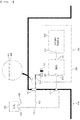
- FIG. 1 is a schematic view of a conventional vehicle battery fire sensing apparatus.
- a battery pack 200 which includes a battery module 210, a battery management system (BMS) 220 configured to generally control the charging and discharging operation of a battery, and a battery pack case 230 configured to receive the battery module and the battery management system, is fixed to a vehicle structure 100.
- BMS battery management system
- a gas discharge portion 231 configured to allow gas or pressure to be discharged therethrough when fire breaks out or thermal runaway occurs in the battery pack is mounted at the battery pack case 230.
- the temperature or voltage of a battery cell is sensed, and upon determining that the battery cell is in an abnormal state, the result of determination is transmitted to an electronic control unit 300. That is, information related to the battery module 210 and the battery management system (BMS) 220 is transmitted to the electronic control unit 300 via a first connector 110, a sixth connector 310, and a first communication means 410.
- BMS battery management system
- a temperature sensor (not shown) or a voltage sensor (not shown) may be damaged, whereby it is not possible to accurately sense the state of the battery.
- the battery management system may not be properly operated, whereby protection measures for a passenger may not be properly taken.
- Korean Patent Application Publication No. 2013-0028023 discloses a battery pack fire suppression apparatus capable of suppressing fire in a battery pack.
- a tank configured to store a fire extinguishing agent is further formed, whereby space utilization is deteriorated.
- an increase in weight of the battery pack fire suppression apparatus due to the addition of the tank adversely affects fuel economy of a vehicle.
- Korean Patent Application Publication No. 2014-0051704 discloses a battery pack protection apparatus and a battery pack including the same.
- a measurement IC is connected to opposite ends of a battery cell to measure voltage of the battery cell in order to measure the magnitude of current that flows in a power supply path, and whether the measurement IC is abnormal is determined based on the measured magnitude of current.
- the measurement IC which is a part configured to measure battery voltage, temperature, current, etc. in a BMS, may be easily damaged due to fire or thermal runaway, and therefore there is a limitation in fundamentally solving the problem.
- the present invention has been made in view of the above problems, and it is an object of the present invention to provide a vehicle battery fire sensing apparatus and method capable of, when fire breaks out in a battery pack, reliably sensing the same and informing a passenger of the same.
- a vehicle battery fire sensing apparatus includes a battery pack (200) mounted to a vehicle structure, an electronic control unit (300), and at least one communication means, wherein the battery pack (200) includes a battery module (210) including at least one battery cell, a battery management system (220) configured to transmit a signal received from the battery module (210) to the electronic control unit (300), and a battery pack case (230) having a gas discharge portion (231) configured to allow venting gas to be discharged therethrough, and a sensor configured to measure at least one of temperature and pressure is provided outside the battery pack case (230).
- the battery pack (200) includes a battery module (210) including at least one battery cell, a battery management system (220) configured to transmit a signal received from the battery module (210) to the electronic control unit (300), and a battery pack case (230) having a gas discharge portion (231) configured to allow venting gas to be discharged therethrough, and a sensor configured to measure at least one of temperature and pressure is provided outside the battery pack case (230).
- the senor may be a first temperature sensor (232) located adjacent to the gas discharge portion (231), and the vehicle battery fire sensing apparatus may further include a second communication means (420) having one side connected to the first temperature sensor (232) and the other side connected to the electronic control unit (300) not via the battery management system (220).
- the senor may be a first pressure sensor (233) located adjacent to the gas discharge portion (231), and the vehicle battery fire sensing apparatus may further include a fourth communication means (440) having one side connected to the first pressure sensor (233) and the other side connected to the electronic control unit (300) not via the battery management system (220).
- the vehicle battery fire sensing apparatus may further include a second temperature sensor (234) located at a position spaced apart from the first temperature sensor (232) by a predetermined distance and a third communication means (430) having one side connected to the second temperature sensor (234) and the other side connected to the electronic control unit (300) not via the battery management system (220).
- a second temperature sensor located at a position spaced apart from the first temperature sensor (232) by a predetermined distance
- a third communication means (430) having one side connected to the second temperature sensor (234) and the other side connected to the electronic control unit (300) not via the battery management system (220).
- the vehicle battery fire sensing apparatus may further include a second pressure sensor (235) located at a position spaced apart from the first pressure sensor (233) by a predetermined distance and a fifth communication means (450) having one side connected to the second pressure sensor (235) and the other side connected to the electronic control unit (300) not via the battery management system (220).
- a second pressure sensor located at a position spaced apart from the first pressure sensor (233) by a predetermined distance
- a fifth communication means (450) having one side connected to the second pressure sensor (235) and the other side connected to the electronic control unit (300) not via the battery management system (220).
- the gas discharge portion (231) may be at least one of a Gore-Tex membrane and a rupture disk configured to be ruptured when the pressure is equal to or higher than a predetermined pressure.
- a vehicle battery fire sensing method using the vehicle battery fire sensing apparatus includes a first step of measuring at least one of the temperature and the voltage of the battery module, a second step of transmitting a measurement value in the first step to the electronic control unit (ECU) via the battery management system, a third step of the electronic control unit (ECU) receiving the measurement value and determining whether the received measurement value is within a normal range, returning to the first step when the measurement value received by the electronic control unit (ECU) is within the normal range, a fourth step of transmitting a measurement value of at least one of the temperature and the pressure measured by the sensor provided at the battery pack case to the electronic control unit (ECU) when the electronic control unit (ECU) does not receive the measurement value or the received measurement value deviates from the normal range, and a fifth step of the electronic control unit (ECU) determining whether the received measurement value of the battery pack case is within a normal range and transmitting a notification signal.
- the measurement value in the fourth step may be a first temperature and may be transmitted to the ECU via the second communication means.
- the measurement value in the fourth step may be a first pressure and may be transmitted to the ECU via the third communication means.
- the measurement value in the fourth step may include a first temperature, transmitted via the second communication means, and a second temperature, transmitted via the third communication means.
- the vehicle battery fire sensing method using the vehicle battery fire sensing apparatus may further include determining whether the measurement value in the fifth step is within the normal range based on a difference between the first temperature and the second temperature.
- the measurement value in the fourth step may include a first pressure, transmitted via the fourth communication means, and a second pressure, transmitted via the fifth communication means.
- the vehicle battery fire sensing method using the vehicle battery fire sensing apparatus may further include determining whether the measurement value in the fifth step is within the normal range based on a difference between the first pressure and the second pressure.
- sensors configured to measure the temperature and pressure of gas discharged from a gas discharge portion of a battery pack are provided outside a battery pack case and measurement values of the sensors are directly transmitted to an electronic control unit not via a battery management system, whereby it is possible to rapidly transmit a signal indicating whether fire breaks out to the electronic control unit even in the case in which the battery management system or the sensors are damaged due to fire breaking out in the battery pack case.
- the vehicle battery fire sensing apparatus and method according to the present invention only the sensors and communication means are added, whereby it is possible to secure the safety of a passenger in an emergency while minimizing an increase in weight of a vehicle.
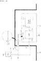
- FIG. 2 is a schematic view of a vehicle battery fire sensing apparatus according to a first preferred embodiment of the present invention.
- the vehicle battery fire sensing apparatus includes a vehicle structure 100, a battery pack 200, an electronic control unit 300, and a communication means 400.
- the vehicle structure 100 is not particularly restricted as long as the battery pack 200 is fixedly mounted thereto.
- the vehicle structure may be a vehicle body.
- the vehicle structure 100 is provided with a first connector 110, through which a first communication means 410 configured to connect the battery management system 220 and the electronic control unit 300 to each other extends, and a second connector 120, through which second to fifth communication means 420, 430, 440, and 450, a description of each of which will follow, extend.
- the second connector 120 will be described below in detail.
- the battery pack 200 includes a battery module 210, a battery management system 220, and a battery pack case 230.
- the battery module 210 includes a cell assembly.
- the cell assembly may be a jelly-roll type cell assembly, which is configured to have a structure in which a long sheet type positive electrode and a long sheet type negative electrode are wound in the state in which a separator is interposed between the positive electrode and the negative electrode, a stacked type cell assembly including unit cells, each of which is configured to have a structure in which a rectangular positive electrode and a rectangular negative electrode are stacked in the state in which a separator is interposed therebetween, a stacked and folded type cell assembly, which is configured to have a structure in which unit cells are wound using a long separation film, or a laminated and stacked type cell assembly, which is configured to have a structure in which the unit cells are stacked in the state in which a separator is interposed therebetween and are then attached to each other.
- the present invention is not limited thereto.
- the cell assembly is mounted in a case, wherein the case is generally configured to have a laminate sheet structure including an inner layer, a metal layer, and an outer layer.
- the inner layer directly contacts the cell assembly, whereby the inner layer must exhibit high insulation properties and high resistance to an electrolytic solution.
- the inner layer must exhibit high sealability in order to hermetically seal the case from the outside, i.e. a thermally-bonded sealed portion between inner layers must exhibit excellent thermal bonding strength.
- the inner layer may be made of a material selected from among a polyolefin-based resin, such as polypropylene, polyethylene, polyethylene-acrylic acid, or polybutylene, a polyurethane resin, and a polyimide resin, which exhibit excellent chemical resistance and high sealability.
- polypropylene which exhibits excellent mechanical-physical properties, such as tensile strength, rigidity, surface hardness, and resistance to impact strength, and excellent chemical resistance, is the most preferably used.
- the metal layer which abuts the inner layer, corresponds to a barrier layer configured to prevent moisture or various kinds of gas from permeating into the battery from the outside.
- Aluminum foil which is light and easily formable, may be used as a preferred material of the metal layer.
- the outer layer is provided on the other surface of the metal layer.
- the outer layer may be made of a heat-resistant polymer that exhibits excellent tensile strength, resistance to moisture permeation, and resistance to air transmission such that the outer layer exhibits high heat resistance and chemical resistance while protecting the cell assembly.
- the outer layer may be made of nylon or polyethylene terephthalate.
- the present invention is not limited thereto.
- leads i.e. a positive electrode lead and a negative electrode lead
- leads are exposed out of the case after being electrically connected to a positive electrode tab and a negative electrode tab of the cell assembly, respectively.
- the battery cell described above corresponds to a generally known construction, and therefore a more detailed description thereof will be omitted.
- a third connector 211 is provided at one side of the battery module 210, and a fourth connector 221 and a fifth connector 222 are provided at opposite sides of the battery management system 220. These connectors are connected to a first communication means 410, e.g. a cable, to transmit the state of the battery module 210 to the electronic control unit 300.
- a first communication means 410 e.g. a cable
- the battery management system 220 which generally controls and manages the battery, such as charging and discharging of the battery, has already been described above, and a detailed description thereof will be omitted.
- the battery pack case 230 is configured to receive and fix the battery module 210 and the battery management system 220, and a gas discharge portion 231 and a first temperature sensor 232 are provided at predetermined positions of the battery pack case.
- a secondary battery is charged and discharged through repeated processes of intercalation and deintercalation of lithium ions in a lithium metal oxide of a positive electrode into and from a graphite electrode of a negative electrode.
- heat is generated and an electrolyte is decomposed by internal short circuit, overcharge, and overdischarge due to external impact, with the result that high-temperature, high-pressure gas is generated.
- the gas discharge potion 231 is configured to rapidly discharge high-temperature, high-pressure gas generated in the battery pack case 230 in order to prevent explosion of the battery pack case.
- the gas discharge potion may be a rupture disk configured to completely isolate the inside of the battery pack case 230 from the outside when the battery module 210 is normally operated and to be ruptured only in an emergency, e.g. when pressure increases to a predetermined level or higher, or may be made of a Gore-Tex membrane material, which is a selective and breathable material, in consideration of the fact that a small amount of gas or moisture may be generated even when the battery module 210 is normally operated.
- the gas discharge potion may be torn in order to prevent explosion of the battery pack case 230 when pressure in the battery pack case abnormally increases.
- the first temperature sensor 232 is located at the outer surface of the battery pack case 230 in the state of being adjacent to the gas discharge portion 231, and a second communication means 420 configured to sequentially connect the first temperature sensor 232, the second connector 120, and the electronic control unit 300 to each other may be provided.
- the first temperature sensor 232 mounted to the battery pack case 230 be provided at the outer surface of the battery pack case 230 at a position close to the gas discharge portion 231 in order to rapidly measure the temperature of gas generated from the gas discharge portion 231 or heat in the battery pack case 230.
- the first temperature sensor 232 be located so as to be spaced apart from the gas discharge portion 231 by about 5 to 50 mm in order to sense meaningful temperature within 5 minutes in consideration of the GB standards and EVS-GTR described above.
- One side of the second communication means 420 is connected to the first temperature sensor 232, and the other side of the second communication means is connected to the electronic control unit 300.
- the second communication means 420 is not particularly restricted as long as the second communication means is capable of transmitting a measurement value of the first temperature sensor 232 to the electronic control unit 300, it is preferable to further provide a first protective cover 421 made of a heat-resistant material capable of enduring a predetermined temperature without being burned for 5 minutes or more outside the battery pack case when the battery module catches fire.
- the first protective cover 421 may be made of a polymer, such as cross-linked polyethylene (XLPE), polyvinyl chloride (PVC), polypropylene (PP), polyamide (PA), or polyethylene terephthalate (PET), or silicone.
- XLPE cross-linked polyethylene
- PVC polyvinyl chloride
- PP polypropylene
- PA polyamide
- PET polyethylene terephthalate
- the first protective cover 421 may completely wrap the second communication means 420 in the state of being in tight contact therewith, or may wrap the second communication means in the state of being slightly spaced apart therefrom.
- the second communication means 420 connected to the first temperature sensor 232 is connected to the electronic control unit 300 not via the battery management system, whereby it is possible to rapidly transmit a measurement value to the electronic control unit even when a sensing part in the battery pack case or the battery management system itself catches fire.
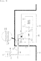
- FIG. 3 is a schematic view of a vehicle battery fire sensing apparatus according to a second preferred embodiment of the present invention.
- the second embodiment is identical to the first embodiment described with reference to FIG. 2 except that a second temperature sensor 233 and a third communication means 430 are further provided.
- a description will be given of only the second temperature sensor 233 and the third communication means 430, which are further provided.
- the second temperature sensor 233 is located at a position spaced apart from the first temperature sensor 232 by a predetermined distance.
- the third communication means 430 one side of which is connected to the second temperature sensor 233 and the other side of which is connected to the electronic control unit 300 via the second connector 120, is further provided.
- a second protective cover 431 made of the same material as the first protective cover 421 may be further provided outside the third communication means 430.
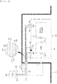
- FIG. 4 is a schematic view of a vehicle battery fire sensing apparatus according to a third preferred embodiment of the present invention.
- the third embodiment is identical to the first embodiment described with reference to FIG. 2 except that a first pressure sensor 234 and a fourth communication means 440 are provided instead of the first temperature sensor 232 and the second communication means 420.
- a description will be given of only the first pressure sensor 234 and the fourth communication means 440.
- the first pressure sensor 234 is located at the outer surface of the battery pack case 230 in the state of being adjacent to the gas discharge portion 231, and the fourth communication means 440 may sequentially connect the first pressure sensor 234, the second connector 120, and the electronic control unit 300 to each other.
- the first pressure sensor 234 mounted to the battery pack case 230 be provided at the outer surface of the battery pack case 230 at a position close to the gas discharge portion 231 in order to rapidly measure the pressure of gas generated from the gas discharge portion 231, for example, the first pressure sensor be located so as to be spaced apart from the gas discharge portion 231 by about 5 to 50 mm, in the same manner as the first temperature sensor 232.
- the fourth communication means 440 Since one side of the fourth communication means 440 is connected to the first pressure sensor 234 and the other side of the fourth communication means is connected to the electronic control unit 300, it is possible to check the pressure of gas discharged from the gas discharge portion 231 not via the battery management system 220.
- a third protective cover 441 made of the same material as the first protective cover 421 may be further provided outside the fourth communication means 440.
- FIG. 5 is an enlarged view showing the position of a pressure sensor according to a third preferred modification of the present invention.
- a holder 236 may be further provided such that the first pressure sensor 234 is located above the gas discharge portion 231.
- the first pressure sensor 234 is seated on the holder 236, as shown in FIG. 5 , it is possible to more accurately measure the pressure of gas generated from the gas discharge portion 231.
- FIG. 6 is a schematic view of a vehicle battery fire sensing apparatus according to a fourth preferred embodiment of the present invention.
- the fourth embodiment is identical to the third embodiment described with reference to FIG. 4 except that a second pressure sensor 235 and a fifth communication means 450 are further provided.
- a description will be given of only the second pressure sensor 235 and the fifth communication means 450, which are further provided.
- the second pressure sensor 235 is located at a position spaced apart from the first pressure sensor 234 by a predetermined distance.
- the fifth communication means 450 one side of which is connected to the second pressure sensor 2350 and the other side of which is connected to the electronic control unit 300 via the second connector 120, is further provided.
- a fourth protective cover 451 made of the same material as the first protective cover 421 may be further provided outside the fifth communication means 450.
- FIG. 7 is a schematic view of a vehicle battery fire sensing apparatus according to a fifth preferred embodiment of the present invention.
- the fifth embodiment is identical to the first embodiment described with reference to FIG. 2 except that a first pressure sensor 234 and a fourth communication means 440 are further provided.
- a description will be given of only the first pressure sensor 234 and the fourth communication means 440, which are further provided.
- the first pressure sensor 234 is provided together with the first temperature sensor 232.
- the fourth communication means 440 which sequentially connects the first pressure sensor 234, the second connector 120, and the electronic control unit 300 to each other, is further provided.
- first temperature sensor 232 and the first pressure sensor 234 are located adjacent to each other in order to rapidly measure the temperature and pressure of gas generated from the gas discharge portion 231, respectively.
- first temperature sensor 232 and the first pressure sensor 234 are installed close to the gas discharge portion 231.
- measurement values of the first temperature sensor 232 and the first pressure sensor 234 are transmitted to the electronic control unit 300 not via the battery management system, whereby it is possible to rapidly transmit the measurement values to the electronic control unit even when the sensing part in the battery pack case or the battery management system itself catches fire. Furthermore, it is possible to transmit both temperature information and pressure information, whereby it is possible to more accurately check the state of the battery pack case.
- FIG. 8 is a schematic view of a vehicle battery fire sensing apparatus according to a sixth preferred embodiment of the present invention.
- the sixth embodiment of the present invention includes all of the constructions of the second embodiment described with reference to FIG. 3 , the fourth embodiment described with reference to FIG. 6 , and the fifth embodiment described with reference to FIG. 7 .
- a first temperature sensor 232 and a first pressure sensor 234 capable of simultaneously measuring both the temperature and pressure of gas generated from a gas discharge portion 231 is located at a vehicle structure so as to be close to the gas discharge portion 231, and a second communication means 420 and a fourth communication means 440, which are configured to transmit measurement values of the first temperature sensor and the first pressure sensor to an electronic control unit 300, are connected to the first temperature sensor and the first pressure sensor, respectively.
- a second temperature sensor 233 and a second pressure sensor 235 are provided at positions spaced apart from the first temperature sensor 232 and the first pressure sensor 234 by predetermined distances, and a third communication means 430 and a fifth communication means 450 are provided correspondingly.
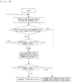
- FIG. 9 is an algorithm illustrating a sensing method using the vehicle battery fire sensing apparatus according to the first preferred embodiment of the present invention.
- the sensing method may include a first step of measuring at least one of the temperature and voltage of the battery cell, a second step of transmitting a measurement value in the first step to the ECU via the first communication means, a third step of the ECU receiving the measurement value and determining whether the received measurement value is within a normal range, a fourth step of transmitting a first temperature value to the ECU via the second communication means in the case in which the third step is not satisfied, and a fifth step of determining whether the received first temperature value is within a normal range and transmitting a notification signal.
- the first step is a step of continuously or discontinuously measuring the temperature and voltage of the battery cell received in the battery pack case.
- the temperature or voltage of the battery cell may be measured.
- the second step is a step of transmitting the temperature and/or the voltage measured in the first step, i.e. information about the battery module and the BMS, to the ECU via the first communication means, which directly connects the battery module and the BMS to the ECU.
- the third step is a step of determining whether the ECU properly receives the transmitted temperature and/or voltage measurement value or whether the received measurement value is within a predetermined normal range.
- the first step of continuously or discontinuously measuring the temperature and voltage of the battery cell and the second step are repeatedly performed.
- the fourth step is a step of transmitting a first temperature value to the ECU via the second communication means in the case in which the ECU does not receive the temperature and/or voltage measurement value or in the case in which, although the measurement value is received, the received measurement value deviates from the normal range.
- the reason that the ECU does not properly receive the temperature and/or voltage measurement value is that the first communication means is not properly operated due to various causes in the battery pack, such as fire or heat, and in the case in which, although the measurement value is received, the received measurement value deviates from the normal range, there is a high possibility of the emergency described above being imminent. Consequently, the first temperature value is transmitted to the ECU via the second communication means outside the battery pack.
- the fifth step is a step of determining the situation in the battery pack based on the first temperature value transmitted via the second communication means.
- the first temperature value is within a normal range
- simple physical short circuit of the first communication means is expected, and therefore a driver is informed that inspection is necessary through a display device of a vehicle.
- the first temperature value is within an abnormal range
- there is a strong possibility of the battery pack overheating or catching fire and therefore the driver is informed that it is necessary to rapidly evacuate the vehicle.
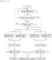
- FIG. 10 is an algorithm illustrating a sensing method using the vehicle battery fire sensing apparatus according to the second preferred embodiment of the present invention.
- a first step to a third step are identical to those of the sensing method described with reference to FIG. 9 .
- a description of the first step to the third step will be omitted, and only different constructions will be described.
- the sensing method may include a fourth step of transmitting a first temperature value and a second temperature value to the ECU via the second communication means and the third communication means, respectively, in the case in which the third step is not satisfied, and a fifth step of comparing the received first temperature value and the received second temperature value with each other, determining whether the received first temperature value and the received second temperature value are within a normal range, and transmitting a notification signal.
- the fourth step is a step of transmitting a first temperature value to the ECU via the second communication means and transmitting a second temperature value to the ECU via the third communication means in the case in which the ECU does not receive the temperature and/or voltage measurement value or in the case in which, although the measurement value is received, the received measurement value deviates from the normal range.
- the fifth step is a step of determining the situation in the battery pack based on the difference between the first temperature value and the second temperature value transmitted via the second communication means and the third communication means. That is, in the case in which the difference between the first temperature value and the second temperature value is within a normal range, simple physical short circuit of the first communication means is expected, and therefore the driver is informed that inspection is necessary through the display device of the vehicle. On the other hand, in the case in which the difference between the first temperature value, measured by the first temperature sensor located close to the gas discharge portion, and the second temperature value, measured by the second temperature sensor located spaced apart from the gas discharge portion by a predetermined distance, is within an abnormal range, i.e. the first temperature value is higher by a determined range or more than the second temperature value, there is a strong possibility of the battery pack overheating or catching fire, and therefore the driver is informed that it is necessary to rapidly evacuate the vehicle.
- a sensing method using the vehicle battery fire sensing apparatus is identical to the sensing method described with reference to FIG. 9 except that a first pressure value is transmitted to the ECU via the fourth communication means
- a sensing method using the vehicle battery fire sensing apparatus according to the fourth preferred embodiment of the present invention is identical to the sensing method described with reference to FIG. 10 except that a first pressure value and a second pressure value are transmitted to the ECU via the fourth communication means and the fifth communication means, respectively, and therefore a detailed description of each of the sensing methods will be omitted.
- the sensing method of the first embodiment and the sensing method of the third embodiment are simultaneously realized, and therefore a detailed description of the sensing method will be omitted.
- FIG. 11 is an algorithm illustrating a sensing method using the vehicle battery fire sensing apparatus according to the sixth preferred embodiment of the present invention.
- a first step to a third step are identical to those of the sensing method described with reference to FIG. 9 .
- a description of the first step to the third step will be omitted, and only different constructions will be described.
- the sensing method may include a fourth step of transmitting a first temperature value, a second temperature value, a first pressure value, and a second pressure value to the ECU via the second communication means to the fifth communication means, respectively, in the case in which the third step is not satisfied, and a fifth step of comparing the difference between the received first temperature value and the received second temperature value with each other, comparing the difference between the received first pressure value and the received second pressure value with each other, determining whether each difference value is within a normal range, and transmitting a notification signal.
- the fifth step not only the difference between the temperature values but also the difference between the pressure values are compared with each other, whereby it is possible to further accurately determine the situation in the battery pack.
Landscapes
- Engineering & Computer Science (AREA)
- Chemical & Material Sciences (AREA)
- Chemical Kinetics & Catalysis (AREA)
- Electrochemistry (AREA)
- General Chemical & Material Sciences (AREA)
- Manufacturing & Machinery (AREA)
- Power Engineering (AREA)
- Mechanical Engineering (AREA)
- Transportation (AREA)
- Sustainable Energy (AREA)
- Sustainable Development (AREA)
- Life Sciences & Earth Sciences (AREA)
- Public Health (AREA)
- Business, Economics & Management (AREA)
- Emergency Management (AREA)
- Health & Medical Sciences (AREA)
- General Physics & Mathematics (AREA)
- Physics & Mathematics (AREA)
- Microelectronics & Electronic Packaging (AREA)
- Automation & Control Theory (AREA)
- Aviation & Aerospace Engineering (AREA)
- Secondary Cells (AREA)
- Battery Mounting, Suspending (AREA)
- Charge And Discharge Circuits For Batteries Or The Like (AREA)
Abstract
Description
- This application claims the benefit of priority to
Korean Patent Application No. 2019-0129929 filed on October 18, 2019 - The present invention relates to a vehicle battery fire sensing apparatus and method, and more particularly to a vehicle battery fire sensing apparatus configured such that sensors configured to measure the temperature and pressure of gas discharged from a gas discharge portion of a battery pack are provided outside a battery pack case and measurement values of the sensors are directly transmitted to an electronic control unit not via a battery management system, whereby, when fire breaks out in the battery pack case, it is possible to rapidly and accurately inform a passenger of the same, and a vehicle battery fire sensing method.
- With technological development of mobile devices, such as mobile phones, laptop computers, camcorders, and digital cameras, and an increase in the demand therefor, research on secondary batteries, which are capable of being charged and discharged, has been actively conducted. In addition, secondary batteries, which are energy sources substituting fossil fuels causing air pollution, have been applied to an electric vehicle (EV), a hybrid electric vehicle (HEV), and a plug-in hybrid electric vehicle (P-HEV), and therefore there is an increasing necessity for development of secondary batteries.
- There are a nickel-cadmium battery, a nickel-hydride battery, a nickel-zinc battery, and a lithium secondary battery as currently commercialized secondary batteries. Thereamong, the lithium secondary battery is in the spotlight, since the lithium secondary battery has little memory effect, whereby the lithium secondary battery is capable of being freely charged and discharged, has a very low self-discharge rate, and has high energy density, compared to the nickel-based secondary batteries.
- Meanwhile, heat is generated from the lithium secondary battery when the lithium secondary battery is charged and discharged. In the case in which the heat is not effectively removed but is accumulated, degradation of the battery may occur, and the safety of the battery may also be greatly reduced. Particularly, in a battery that requires high-speed charging and discharging characteristics, like a power source for an electric vehicle, a hybrid electric vehicle, etc., generation of a large amount of heat and expansion in volume of the battery occur during a process of instantaneously providing high output.
-
FIG. 1 is a schematic view of a conventional vehicle battery fire sensing apparatus. Referring toFIG. 1 , in the conventional vehicle battery fire sensing apparatus, abattery pack 200, which includes abattery module 210, a battery management system (BMS) 220 configured to generally control the charging and discharging operation of a battery, and abattery pack case 230 configured to receive the battery module and the battery management system, is fixed to avehicle structure 100. In addition, agas discharge portion 231 configured to allow gas or pressure to be discharged therethrough when fire breaks out or thermal runaway occurs in the battery pack is mounted at thebattery pack case 230. - In the conventional vehicle battery fire sensing apparatus described above, the temperature or voltage of a battery cell is sensed, and upon determining that the battery cell is in an abnormal state, the result of determination is transmitted to an
electronic control unit 300. That is, information related to thebattery module 210 and the battery management system (BMS) 220 is transmitted to theelectronic control unit 300 via afirst connector 110, asixth connector 310, and a first communication means 410. - In the case in which fire breaks out in the battery pack, however, a temperature sensor (not shown) or a voltage sensor (not shown) may be damaged, whereby it is not possible to accurately sense the state of the battery. Furthermore, in the case in which fire breaks out in the vicinity of the battery management system, the battery management system may not be properly operated, whereby protection measures for a passenger may not be properly taken.
- As a conventional art for solving the above problem,
Korean Patent Application Publication No. 2013-0028023 - In addition,
Korean Patent Application Publication No. 2014-0051704 - GB standards (Chinese national standards on the safety of electric vehicle batteries, which are expected to be enforced in July of 2020) and EVS-GTR (Global Technical Regulation on Electric Vehicle Safety), which will be established and enforced within a few years, require that a vehicle warn a passenger of danger 5 minutes before danger occurs in a passenger space due to thermal diffusion caused by thermal runaway or fire of a battery as compulsory regulations.
- However, in the case in which the BMS is damaged and thus the function of the BMS is lost, as described above, it is not possible to warn the passenger of danger. Therefore, there is an urgent necessity for development of technology related thereto.
-
- (Patent Document 1)
Korean Patent Application Publication No. 2013-0028023 - (Patent Document 2)
Korean Patent Application Publication No. 2014-0051704 - The present invention has been made in view of the above problems, and it is an object of the present invention to provide a vehicle battery fire sensing apparatus and method capable of, when fire breaks out in a battery pack, reliably sensing the same and informing a passenger of the same.
- It is another object of the present invention to provide a vehicle battery fire sensing apparatus and method capable of accurately sensing the situation in a battery pack while minimizing an increase in weight of a vehicle.
- In order to accomplish the above object, a vehicle battery fire sensing apparatus according to the present invention includes a battery pack (200) mounted to a vehicle structure, an electronic control unit (300), and at least one communication means, wherein the battery pack (200) includes a battery module (210) including at least one battery cell, a battery management system (220) configured to transmit a signal received from the battery module (210) to the electronic control unit (300), and a battery pack case (230) having a gas discharge portion (231) configured to allow venting gas to be discharged therethrough, and a sensor configured to measure at least one of temperature and pressure is provided outside the battery pack case (230).
- Also, in the vehicle battery fire sensing apparatus according to the present invention, the sensor may be a first temperature sensor (232) located adjacent to the gas discharge portion (231), and the vehicle battery fire sensing apparatus may further include a second communication means (420) having one side connected to the first temperature sensor (232) and the other side connected to the electronic control unit (300) not via the battery management system (220).
- Also, in the vehicle battery fire sensing apparatus according to the present invention, the sensor may be a first pressure sensor (233) located adjacent to the gas discharge portion (231), and the vehicle battery fire sensing apparatus may further include a fourth communication means (440) having one side connected to the first pressure sensor (233) and the other side connected to the electronic control unit (300) not via the battery management system (220).
- Also, the vehicle battery fire sensing apparatus according to the present invention may further include a second temperature sensor (234) located at a position spaced apart from the first temperature sensor (232) by a predetermined distance and a third communication means (430) having one side connected to the second temperature sensor (234) and the other side connected to the electronic control unit (300) not via the battery management system (220).
- Also, the vehicle battery fire sensing apparatus according to the present invention may further include a second pressure sensor (235) located at a position spaced apart from the first pressure sensor (233) by a predetermined distance and a fifth communication means (450) having one side connected to the second pressure sensor (235) and the other side connected to the electronic control unit (300) not via the battery management system (220).
- Also, in the vehicle battery fire sensing apparatus according to the present invention, the gas discharge portion (231) may be at least one of a Gore-Tex membrane and a rupture disk configured to be ruptured when the pressure is equal to or higher than a predetermined pressure.
- In addition, a vehicle battery fire sensing method using the vehicle battery fire sensing apparatus according to the present invention includes a first step of measuring at least one of the temperature and the voltage of the battery module, a second step of transmitting a measurement value in the first step to the electronic control unit (ECU) via the battery management system, a third step of the electronic control unit (ECU) receiving the measurement value and determining whether the received measurement value is within a normal range, returning to the first step when the measurement value received by the electronic control unit (ECU) is within the normal range, a fourth step of transmitting a measurement value of at least one of the temperature and the pressure measured by the sensor provided at the battery pack case to the electronic control unit (ECU) when the electronic control unit (ECU) does not receive the measurement value or the received measurement value deviates from the normal range, and a fifth step of the electronic control unit (ECU) determining whether the received measurement value of the battery pack case is within a normal range and transmitting a notification signal.
- Also, in the vehicle battery fire sensing method using the vehicle battery fire sensing apparatus according to the present invention, the measurement value in the fourth step may be a first temperature and may be transmitted to the ECU via the second communication means.
- Also, in the vehicle battery fire sensing method using the vehicle battery fire sensing apparatus according to the present invention, the measurement value in the fourth step may be a first pressure and may be transmitted to the ECU via the third communication means.
- Also, in the vehicle battery fire sensing method using the vehicle battery fire sensing apparatus according to the present invention, the measurement value in the fourth step may include a first temperature, transmitted via the second communication means, and a second temperature, transmitted via the third communication means.
- Also, the vehicle battery fire sensing method using the vehicle battery fire sensing apparatus according to the present invention may further include determining whether the measurement value in the fifth step is within the normal range based on a difference between the first temperature and the second temperature.
- Also, in the vehicle battery fire sensing method using the vehicle battery fire sensing apparatus according to the present invention, the measurement value in the fourth step may include a first pressure, transmitted via the fourth communication means, and a second pressure, transmitted via the fifth communication means.
- Also, the vehicle battery fire sensing method using the vehicle battery fire sensing apparatus according to the present invention may further include determining whether the measurement value in the fifth step is within the normal range based on a difference between the first pressure and the second pressure.
- In a vehicle battery fire sensing apparatus and method according to the present invention, sensors configured to measure the temperature and pressure of gas discharged from a gas discharge portion of a battery pack are provided outside a battery pack case and measurement values of the sensors are directly transmitted to an electronic control unit not via a battery management system, whereby it is possible to rapidly transmit a signal indicating whether fire breaks out to the electronic control unit even in the case in which the battery management system or the sensors are damaged due to fire breaking out in the battery pack case.
- Also, in the vehicle battery fire sensing apparatus and method according to the present invention, only the sensors and communication means are added, whereby it is possible to secure the safety of a passenger in an emergency while minimizing an increase in weight of a vehicle.
-
-
FIG. 1 is a schematic view of a conventional vehicle battery fire sensing apparatus. -
FIG. 2 is a schematic view of a vehicle battery fire sensing apparatus according to a first preferred embodiment of the present invention. -
FIG. 3 is a schematic view of a vehicle battery fire sensing apparatus according to a second preferred embodiment of the present invention. -
FIG. 4 is a schematic view of a vehicle battery fire sensing apparatus according to a third preferred embodiment of the present invention. -
FIG. 5 is an enlarged view showing the position of a pressure sensor according to a third preferred modification of the present invention. -
FIG. 6 is a schematic view of a vehicle battery fire sensing apparatus according to a fourth preferred embodiment of the present invention. -
FIG. 7 is a schematic view of a vehicle battery fire sensing apparatus according to a fifth preferred embodiment of the present invention. -
FIG. 8 is a schematic view of a vehicle battery fire sensing apparatus according to a sixth preferred embodiment of the present invention. -
FIG. 9 is an algorithm illustrating a sensing method using the vehicle battery fire sensing apparatus according to the first preferred embodiment of the present invention. -
FIG. 10 is an algorithm illustrating a sensing method using the vehicle battery fire sensing apparatus according to the second preferred embodiment of the present invention. -
FIG. 11 is an algorithm illustrating a sensing method using the vehicle battery fire sensing apparatus according to the sixth preferred embodiment of the present invention. - In the present application, it should be understood that the terms "comprises," "has," "includes," etc. specify the presence of stated features, numbers, steps, operations, elements, components, or combinations thereof, but do not preclude the presence or addition of one or more other features, numbers, steps, operations, elements, components, or combinations thereof.
- In addition, the same reference numbers will be used throughout the drawings to refer to parts that perform similar functions or operations. In the case in which one part is said to be connected to another part in the entire specification, not only may the one part be directly connected to the other part, but also, the one part may be indirectly connected to the other part via a further part. In addition, that a certain element is included does not mean that other elements are excluded, but means that such elements may be further included unless mentioned otherwise.
- Hereinafter, a vehicle battery fire sensing apparatus and method according to the present invention will be described with reference to the accompanying drawings.
-
FIG. 2 is a schematic view of a vehicle battery fire sensing apparatus according to a first preferred embodiment of the present invention. - Referring to
FIG. 2 , the vehicle battery fire sensing apparatus according to the first preferred embodiment of the present invention includes avehicle structure 100, abattery pack 200, anelectronic control unit 300, and a communication means 400. - The
vehicle structure 100 is not particularly restricted as long as thebattery pack 200 is fixedly mounted thereto. As an example, the vehicle structure may be a vehicle body. Thevehicle structure 100 is provided with afirst connector 110, through which a first communication means 410 configured to connect thebattery management system 220 and theelectronic control unit 300 to each other extends, and asecond connector 120, through which second to fifth communication means 420, 430, 440, and 450, a description of each of which will follow, extend. Thesecond connector 120 will be described below in detail. - The
battery pack 200 includes abattery module 210, abattery management system 220, and abattery pack case 230. - The
battery module 210 includes a cell assembly. The cell assembly may be a jelly-roll type cell assembly, which is configured to have a structure in which a long sheet type positive electrode and a long sheet type negative electrode are wound in the state in which a separator is interposed between the positive electrode and the negative electrode, a stacked type cell assembly including unit cells, each of which is configured to have a structure in which a rectangular positive electrode and a rectangular negative electrode are stacked in the state in which a separator is interposed therebetween, a stacked and folded type cell assembly, which is configured to have a structure in which unit cells are wound using a long separation film, or a laminated and stacked type cell assembly, which is configured to have a structure in which the unit cells are stacked in the state in which a separator is interposed therebetween and are then attached to each other. However, the present invention is not limited thereto. - The cell assembly is mounted in a case, wherein the case is generally configured to have a laminate sheet structure including an inner layer, a metal layer, and an outer layer. The inner layer directly contacts the cell assembly, whereby the inner layer must exhibit high insulation properties and high resistance to an electrolytic solution. In addition, the inner layer must exhibit high sealability in order to hermetically seal the case from the outside, i.e. a thermally-bonded sealed portion between inner layers must exhibit excellent thermal bonding strength. The inner layer may be made of a material selected from among a polyolefin-based resin, such as polypropylene, polyethylene, polyethylene-acrylic acid, or polybutylene, a polyurethane resin, and a polyimide resin, which exhibit excellent chemical resistance and high sealability. However, the present invention is not limited thereto, and polypropylene, which exhibits excellent mechanical-physical properties, such as tensile strength, rigidity, surface hardness, and resistance to impact strength, and excellent chemical resistance, is the most preferably used.
- The metal layer, which abuts the inner layer, corresponds to a barrier layer configured to prevent moisture or various kinds of gas from permeating into the battery from the outside. Aluminum foil, which is light and easily formable, may be used as a preferred material of the metal layer.
- The outer layer is provided on the other surface of the metal layer. The outer layer may be made of a heat-resistant polymer that exhibits excellent tensile strength, resistance to moisture permeation, and resistance to air transmission such that the outer layer exhibits high heat resistance and chemical resistance while protecting the cell assembly. As an example, the outer layer may be made of nylon or polyethylene terephthalate. However, the present invention is not limited thereto.
- Meanwhile, leads, i.e. a positive electrode lead and a negative electrode lead, are exposed out of the case after being electrically connected to a positive electrode tab and a negative electrode tab of the cell assembly, respectively. The battery cell described above corresponds to a generally known construction, and therefore a more detailed description thereof will be omitted.
- Meanwhile, a
third connector 211 is provided at one side of thebattery module 210, and afourth connector 221 and afifth connector 222 are provided at opposite sides of thebattery management system 220. These connectors are connected to a first communication means 410, e.g. a cable, to transmit the state of thebattery module 210 to theelectronic control unit 300. - The
battery management system 220, which generally controls and manages the battery, such as charging and discharging of the battery, has already been described above, and a detailed description thereof will be omitted. - The
battery pack case 230 is configured to receive and fix thebattery module 210 and thebattery management system 220, and agas discharge portion 231 and afirst temperature sensor 232 are provided at predetermined positions of the battery pack case. - In general, a secondary battery is charged and discharged through repeated processes of intercalation and deintercalation of lithium ions in a lithium metal oxide of a positive electrode into and from a graphite electrode of a negative electrode. However, heat is generated and an electrolyte is decomposed by internal short circuit, overcharge, and overdischarge due to external impact, with the result that high-temperature, high-pressure gas is generated.
- The
gas discharge potion 231 is configured to rapidly discharge high-temperature, high-pressure gas generated in thebattery pack case 230 in order to prevent explosion of the battery pack case. - As an example, the gas discharge potion may be a rupture disk configured to completely isolate the inside of the
battery pack case 230 from the outside when thebattery module 210 is normally operated and to be ruptured only in an emergency, e.g. when pressure increases to a predetermined level or higher, or may be made of a Gore-Tex membrane material, which is a selective and breathable material, in consideration of the fact that a small amount of gas or moisture may be generated even when thebattery module 210 is normally operated. Of course, even in the case in which the gas discharge potion is made of a Gore-Tex membrane material, it is obvious that the gas discharge potion may be torn in order to prevent explosion of thebattery pack case 230 when pressure in the battery pack case abnormally increases. - The
first temperature sensor 232 is located at the outer surface of thebattery pack case 230 in the state of being adjacent to thegas discharge portion 231, and a second communication means 420 configured to sequentially connect thefirst temperature sensor 232, thesecond connector 120, and theelectronic control unit 300 to each other may be provided. - Specifically, it is preferable that the
first temperature sensor 232 mounted to thebattery pack case 230 be provided at the outer surface of thebattery pack case 230 at a position close to thegas discharge portion 231 in order to rapidly measure the temperature of gas generated from thegas discharge portion 231 or heat in thebattery pack case 230. - For example, it is preferable that the
first temperature sensor 232 be located so as to be spaced apart from thegas discharge portion 231 by about 5 to 50 mm in order to sense meaningful temperature within 5 minutes in consideration of the GB standards and EVS-GTR described above. - One side of the second communication means 420 is connected to the
first temperature sensor 232, and the other side of the second communication means is connected to theelectronic control unit 300. - Here, although the second communication means 420 is not particularly restricted as long as the second communication means is capable of transmitting a measurement value of the
first temperature sensor 232 to theelectronic control unit 300, it is preferable to further provide a firstprotective cover 421 made of a heat-resistant material capable of enduring a predetermined temperature without being burned for 5 minutes or more outside the battery pack case when the battery module catches fire. As an example, the firstprotective cover 421 may be made of a polymer, such as cross-linked polyethylene (XLPE), polyvinyl chloride (PVC), polypropylene (PP), polyamide (PA), or polyethylene terephthalate (PET), or silicone. However, the present invention is not limited thereto. The firstprotective cover 421 may completely wrap the second communication means 420 in the state of being in tight contact therewith, or may wrap the second communication means in the state of being slightly spaced apart therefrom. - In a conventional case, a method of transmitting a signal to the electronic control unit via the battery management system when the battery module catches fire was used. In the case in which the battery management system itself is damaged by sudden fire, however, it was not possible to recognize the situation in the battery pack at all.
- According to the first embodiment of the present invention, however, the second communication means 420 connected to the
first temperature sensor 232 is connected to theelectronic control unit 300 not via the battery management system, whereby it is possible to rapidly transmit a measurement value to the electronic control unit even when a sensing part in the battery pack case or the battery management system itself catches fire. -
FIG. 3 is a schematic view of a vehicle battery fire sensing apparatus according to a second preferred embodiment of the present invention. - The second embodiment is identical to the first embodiment described with reference to
FIG. 2 except that asecond temperature sensor 233 and a third communication means 430 are further provided. Hereinafter, therefore, a description will be given of only thesecond temperature sensor 233 and the third communication means 430, which are further provided. - In the second preferred embodiment of the present invention, the
second temperature sensor 233 is located at a position spaced apart from thefirst temperature sensor 232 by a predetermined distance. In addition, the third communication means 430, one side of which is connected to thesecond temperature sensor 233 and the other side of which is connected to theelectronic control unit 300 via thesecond connector 120, is further provided. - Here, a second
protective cover 431 made of the same material as the firstprotective cover 421 may be further provided outside the third communication means 430. -
FIG. 4 is a schematic view of a vehicle battery fire sensing apparatus according to a third preferred embodiment of the present invention. - The third embodiment is identical to the first embodiment described with reference to
FIG. 2 except that afirst pressure sensor 234 and a fourth communication means 440 are provided instead of thefirst temperature sensor 232 and the second communication means 420. Hereinafter, therefore, a description will be given of only thefirst pressure sensor 234 and the fourth communication means 440. - The
first pressure sensor 234 is located at the outer surface of thebattery pack case 230 in the state of being adjacent to thegas discharge portion 231, and the fourth communication means 440 may sequentially connect thefirst pressure sensor 234, thesecond connector 120, and theelectronic control unit 300 to each other. - Specifically, it is preferable that the
first pressure sensor 234 mounted to thebattery pack case 230 be provided at the outer surface of thebattery pack case 230 at a position close to thegas discharge portion 231 in order to rapidly measure the pressure of gas generated from thegas discharge portion 231, for example, the first pressure sensor be located so as to be spaced apart from thegas discharge portion 231 by about 5 to 50 mm, in the same manner as thefirst temperature sensor 232. - Since one side of the fourth communication means 440 is connected to the
first pressure sensor 234 and the other side of the fourth communication means is connected to theelectronic control unit 300, it is possible to check the pressure of gas discharged from thegas discharge portion 231 not via thebattery management system 220. - It is obvious that a third
protective cover 441 made of the same material as the firstprotective cover 421 may be further provided outside the fourth communication means 440. -
FIG. 5 is an enlarged view showing the position of a pressure sensor according to a third preferred modification of the present invention. As shown inFIG. 5 , aholder 236 may be further provided such that thefirst pressure sensor 234 is located above thegas discharge portion 231. In the case in which thefirst pressure sensor 234 is seated on theholder 236, as shown inFIG. 5 , it is possible to more accurately measure the pressure of gas generated from thegas discharge portion 231. -
FIG. 6 is a schematic view of a vehicle battery fire sensing apparatus according to a fourth preferred embodiment of the present invention. - The fourth embodiment is identical to the third embodiment described with reference to
FIG. 4 except that asecond pressure sensor 235 and a fifth communication means 450 are further provided. Hereinafter, therefore, a description will be given of only thesecond pressure sensor 235 and the fifth communication means 450, which are further provided. - In the fourth preferred embodiment of the present invention, the
second pressure sensor 235 is located at a position spaced apart from thefirst pressure sensor 234 by a predetermined distance. In addition, the fifth communication means 450, one side of which is connected to the second pressure sensor 2350 and the other side of which is connected to theelectronic control unit 300 via thesecond connector 120, is further provided. - A fourth
protective cover 451 made of the same material as the firstprotective cover 421 may be further provided outside the fifth communication means 450. -
FIG. 7 is a schematic view of a vehicle battery fire sensing apparatus according to a fifth preferred embodiment of the present invention. - The fifth embodiment is identical to the first embodiment described with reference to
FIG. 2 except that afirst pressure sensor 234 and a fourth communication means 440 are further provided. Hereinafter, therefore, a description will be given of only thefirst pressure sensor 234 and the fourth communication means 440, which are further provided. - In the fifth preferred embodiment of the present invention, the
first pressure sensor 234 is provided together with thefirst temperature sensor 232. In addition, the fourth communication means 440, which sequentially connects thefirst pressure sensor 234, thesecond connector 120, and theelectronic control unit 300 to each other, is further provided. - Here, the
first temperature sensor 232 and thefirst pressure sensor 234 are located adjacent to each other in order to rapidly measure the temperature and pressure of gas generated from thegas discharge portion 231, respectively. In addition, thefirst temperature sensor 232 and thefirst pressure sensor 234 are installed close to thegas discharge portion 231. - According to the fifth embodiment of the present invention, as described above, measurement values of the
first temperature sensor 232 and thefirst pressure sensor 234 are transmitted to theelectronic control unit 300 not via the battery management system, whereby it is possible to rapidly transmit the measurement values to the electronic control unit even when the sensing part in the battery pack case or the battery management system itself catches fire. Furthermore, it is possible to transmit both temperature information and pressure information, whereby it is possible to more accurately check the state of the battery pack case. -
FIG. 8 is a schematic view of a vehicle battery fire sensing apparatus according to a sixth preferred embodiment of the present invention. - The sixth embodiment of the present invention includes all of the constructions of the second embodiment described with reference to
FIG. 3 , the fourth embodiment described with reference toFIG. 6 , and the fifth embodiment described with reference toFIG. 7 . - That is, in a
battery pack case 230, afirst temperature sensor 232 and afirst pressure sensor 234 capable of simultaneously measuring both the temperature and pressure of gas generated from agas discharge portion 231 is located at a vehicle structure so as to be close to thegas discharge portion 231, and a second communication means 420 and a fourth communication means 440, which are configured to transmit measurement values of the first temperature sensor and the first pressure sensor to anelectronic control unit 300, are connected to the first temperature sensor and the first pressure sensor, respectively. In addition, asecond temperature sensor 233 and asecond pressure sensor 235 are provided at positions spaced apart from thefirst temperature sensor 232 and thefirst pressure sensor 234 by predetermined distances, and a third communication means 430 and a fifth communication means 450 are provided correspondingly. - Hereinafter, a sensing method using the vehicle battery fire sensing apparatus according to any one of the first to sixth embodiments described above will be described in detail.
-
FIG. 9 is an algorithm illustrating a sensing method using the vehicle battery fire sensing apparatus according to the first preferred embodiment of the present invention. - The sensing method may include a first step of measuring at least one of the temperature and voltage of the battery cell, a second step of transmitting a measurement value in the first step to the ECU via the first communication means, a third step of the ECU receiving the measurement value and determining whether the received measurement value is within a normal range, a fourth step of transmitting a first temperature value to the ECU via the second communication means in the case in which the third step is not satisfied, and a fifth step of determining whether the received first temperature value is within a normal range and transmitting a notification signal.
- Specifically, the first step is a step of continuously or discontinuously measuring the temperature and voltage of the battery cell received in the battery pack case. Here, only the temperature or voltage of the battery cell may be measured. However, it is preferable that both the temperature and voltage of the battery cell be measured in order to more accurately check the state of the battery cell.
- The second step is a step of transmitting the temperature and/or the voltage measured in the first step, i.e. information about the battery module and the BMS, to the ECU via the first communication means, which directly connects the battery module and the BMS to the ECU.
- The third step is a step of determining whether the ECU properly receives the transmitted temperature and/or voltage measurement value or whether the received measurement value is within a predetermined normal range. In the case in which the ECU normally receives the temperature and/or voltage measurement value and the received measurement value is within the normal range, the first step of continuously or discontinuously measuring the temperature and voltage of the battery cell and the second step are repeatedly performed.
- The fourth step is a step of transmitting a first temperature value to the ECU via the second communication means in the case in which the ECU does not receive the temperature and/or voltage measurement value or in the case in which, although the measurement value is received, the received measurement value deviates from the normal range.
- The reason that the ECU does not properly receive the temperature and/or voltage measurement value is that the first communication means is not properly operated due to various causes in the battery pack, such as fire or heat, and in the case in which, although the measurement value is received, the received measurement value deviates from the normal range, there is a high possibility of the emergency described above being imminent. Consequently, the first temperature value is transmitted to the ECU via the second communication means outside the battery pack.
- The fifth step is a step of determining the situation in the battery pack based on the first temperature value transmitted via the second communication means. In the case in which the first temperature value is within a normal range, simple physical short circuit of the first communication means is expected, and therefore a driver is informed that inspection is necessary through a display device of a vehicle. In the case in which the first temperature value is within an abnormal range, on the other hand, there is a strong possibility of the battery pack overheating or catching fire, and therefore the driver is informed that it is necessary to rapidly evacuate the vehicle.
-
FIG. 10 is an algorithm illustrating a sensing method using the vehicle battery fire sensing apparatus according to the second preferred embodiment of the present invention. - A first step to a third step are identical to those of the sensing method described with reference to
FIG. 9 . Hereinafter, therefore, a description of the first step to the third step will be omitted, and only different constructions will be described. - The sensing method may include a fourth step of transmitting a first temperature value and a second temperature value to the ECU via the second communication means and the third communication means, respectively, in the case in which the third step is not satisfied, and a fifth step of comparing the received first temperature value and the received second temperature value with each other, determining whether the received first temperature value and the received second temperature value are within a normal range, and transmitting a notification signal.
- Specifically, the fourth step is a step of transmitting a first temperature value to the ECU via the second communication means and transmitting a second temperature value to the ECU via the third communication means in the case in which the ECU does not receive the temperature and/or voltage measurement value or in the case in which, although the measurement value is received, the received measurement value deviates from the normal range.
- The fifth step is a step of determining the situation in the battery pack based on the difference between the first temperature value and the second temperature value transmitted via the second communication means and the third communication means. That is, in the case in which the difference between the first temperature value and the second temperature value is within a normal range, simple physical short circuit of the first communication means is expected, and therefore the driver is informed that inspection is necessary through the display device of the vehicle. On the other hand, in the case in which the difference between the first temperature value, measured by the first temperature sensor located close to the gas discharge portion, and the second temperature value, measured by the second temperature sensor located spaced apart from the gas discharge portion by a predetermined distance, is within an abnormal range, i.e. the first temperature value is higher by a determined range or more than the second temperature value, there is a strong possibility of the battery pack overheating or catching fire, and therefore the driver is informed that it is necessary to rapidly evacuate the vehicle.
- Meanwhile, a sensing method using the vehicle battery fire sensing apparatus according to the third preferred embodiment of the present invention is identical to the sensing method described with reference to
FIG. 9 except that a first pressure value is transmitted to the ECU via the fourth communication means, and a sensing method using the vehicle battery fire sensing apparatus according to the fourth preferred embodiment of the present invention is identical to the sensing method described with reference toFIG. 10 except that a first pressure value and a second pressure value are transmitted to the ECU via the fourth communication means and the fifth communication means, respectively, and therefore a detailed description of each of the sensing methods will be omitted. - Also, in a sensing method using the vehicle battery fire sensing apparatus according to the fifth preferred embodiment of the present invention, the sensing method of the first embodiment and the sensing method of the third embodiment are simultaneously realized, and therefore a detailed description of the sensing method will be omitted.
-
FIG. 11 is an algorithm illustrating a sensing method using the vehicle battery fire sensing apparatus according to the sixth preferred embodiment of the present invention. - A first step to a third step are identical to those of the sensing method described with reference to
FIG. 9 . Hereinafter, therefore, a description of the first step to the third step will be omitted, and only different constructions will be described. - The sensing method may include a fourth step of transmitting a first temperature value, a second temperature value, a first pressure value, and a second pressure value to the ECU via the second communication means to the fifth communication means, respectively, in the case in which the third step is not satisfied, and a fifth step of comparing the difference between the received first temperature value and the received second temperature value with each other, comparing the difference between the received first pressure value and the received second pressure value with each other, determining whether each difference value is within a normal range, and transmitting a notification signal.
- Particularly, in the fifth step, not only the difference between the temperature values but also the difference between the pressure values are compared with each other, whereby it is possible to further accurately determine the situation in the battery pack.
- Although the specific details of the present invention have been described in detail, those skilled in the art will appreciate that the detailed description thereof discloses only preferred embodiments of the present invention and thus does not limit the scope of the present invention. Accordingly, those skilled in the art will appreciate that various changes and modifications are possible, without departing from the category and the technical idea of the present invention, and it will be obvious that such changes and modifications fall within the scope of the appended claims.
-
- 100: Vehicle structure
- 110: First connector
- 120: Second connector
- 200: Battery pack
- 210: Battery module
- 211: Third connector
- 220: Battery management system
- 221: Fourth connector 222: Fifth connector
- 230: Battery pack case
- 231: Gas discharge portion 232: First temperature sensor
- 233: Second temperature sensor 234: First pressure sensor
- 235: Second pressure sensor 236: Holder
- 300: Electronic control unit (ECU)
- 310: Sixth connector
- 400: Communication means
- 410: First communication means
- 420: Second communication means
- 421: First protective cover
- 430: Third communication means
- 431: Second protective cover
- 440: Fourth communication means
- 441: Third protective cover
- 450: Fifth communication means
- 451: Fourth protective cover
Claims (13)
- A vehicle battery fire sensing apparatus comprising:a battery pack mounted to a vehicle structure;an electronic control unit; andat least one communication means,wherein the battery pack comprises a battery module comprising at least one battery cell, a battery management system configured to transmit a signal received from the battery module to the electronic control unit, and a battery pack case having a gas discharge portion configured to allow venting gas to be discharged therethrough, andwherein the battery pack case is provided with a sensor configured to measure at least one of temperature and pressure.
- The vehicle battery fire sensing apparatus according to claim 1, wherein the sensor is a first temperature sensor located adjacent to the gas discharge portion, and
wherein the vehicle battery fire sensing apparatus further comprises a second communication means having one side connected to the first temperature sensor and the other side connected to the electronic control unit not via the battery management system. - The vehicle battery fire sensing apparatus according to claim 1, wherein the sensor is a first pressure sensor located adjacent to the gas discharge portion, and
wherein the vehicle battery fire sensing apparatus further comprises a fourth communication means having one side connected to the first pressure sensor and the other side connected to the electronic control unit not via the battery management system. - The vehicle battery fire sensing apparatus according to claim 2, further comprising:a second temperature sensor located spaced apart from the first temperature sensor by a predetermined distance; anda third communication means having one side connected to the second temperature sensor and the other side connected to the electronic control unit not via the battery management system.
- The vehicle battery fire sensing apparatus according to claim 3, further comprising:a second pressure sensor located spaced apart from the first pressure sensor by a predetermined distance; anda fifth communication means having one side connected to the second pressure sensor and the other side connected to the electronic control unit not via the battery management system.
- The vehicle battery fire sensing apparatus according to claim 1, wherein the gas discharge portion is at least one of a Gore-Tex membrane and a rupture disk configured to be ruptured when the pressure is equal to or higher than a predetermined pressure.
- A vehicle battery fire sensing method using the vehicle battery fire sensing apparatus according to any one of claims 1 to 6, the vehicle battery fire sensing method comprising:a first step of measuring at least one of temperature and voltage of the battery module;a second step of transmitting a measurement value in the first step to the electronic control unit (ECU) via the battery management system;a third step of the electronic control unit (ECU) receiving the measurement value and determining whether the received measurement value is within a normal range;returning to the first step when the measurement value received by the electronic control unit (ECU) is within the normal range;a fourth step of transmitting a measurement value of at least one of a temperature and a pressure measured by the sensor provided at the battery pack case to the electronic control unit (ECU) when the electronic control unit (ECU) does not receive the measurement value or the received measurement value deviates from the normal range; anda fifth step of the electronic control unit (ECU) determining whether the received measurement value of the battery pack case is within a normal range and transmitting a notification signal.
- The vehicle battery fire sensing method according to claim 7, wherein the measurement value in the fourth step is a first temperature and is transmitted to the ECU via the second communication means.
- The vehicle battery fire sensing method according to claim 7, wherein the measurement value in the fourth step is a first pressure and is transmitted to the ECU via the third communication means.
- The vehicle battery fire sensing method according to claim 7, wherein the measurement value in the fourth step comprises a first temperature, transmitted via the second communication means, and a second temperature, transmitted via the fourth communication means.
- The vehicle battery fire sensing method according to claim 10, further comprising determining whether the measurement value in the fifth step is within the normal range based on a difference between the first temperature and the second temperature.
- The vehicle battery fire sensing method according to claim 7, wherein the measurement value in the fourth step comprises a first pressure, transmitted via the third communication means, and a second pressure, transmitted via the fifth communication means.
- The vehicle battery fire sensing method according to claim 12, further comprising determining whether the measurement value in the fifth step is within the normal range based on a difference between the first pressure and the second pressure.
Applications Claiming Priority (2)
| Application Number | Priority Date | Filing Date | Title |
|---|---|---|---|
| KR1020190129929A KR102808772B1 (en) | 2019-10-18 | 2019-10-18 | Apparatus For Fire Detection of Vehicle Battery and Method Thereof |
| PCT/KR2020/013065 WO2021075759A1 (en) | 2019-10-18 | 2020-09-25 | Vehicle battery fire detection apparatus and detection method |
Publications (2)
| Publication Number | Publication Date |
|---|---|
| EP3923397A1 true EP3923397A1 (en) | 2021-12-15 |
| EP3923397A4 EP3923397A4 (en) | 2022-05-25 |
Family
ID=75537883
Family Applications (1)
| Application Number | Title | Priority Date | Filing Date |
|---|---|---|---|
| EP20877210.3A Pending EP3923397A4 (en) | 2019-10-18 | 2020-09-25 | VEHICLE BATTERY FIRE DETECTION APPARATUS AND DETECTION METHOD |
Country Status (6)
| Country | Link |
|---|---|
| US (1) | US11975615B2 (en) |
| EP (1) | EP3923397A4 (en) |
| JP (1) | JP7191441B2 (en) |
| KR (1) | KR102808772B1 (en) |
| CN (1) | CN113767028B (en) |
| WO (1) | WO2021075759A1 (en) |
Cited By (1)
| Publication number | Priority date | Publication date | Assignee | Title |
|---|---|---|---|---|
| EP4345979A1 (en) * | 2022-09-22 | 2024-04-03 | Huawei Digital Power Technologies Co., Ltd. | Battery cell, battery module, battery pack, energy storage system, and electric vehicle |
Families Citing this family (12)
| Publication number | Priority date | Publication date | Assignee | Title |
|---|---|---|---|---|
| JPWO2022249916A1 (en) * | 2021-05-28 | 2022-12-01 | ||
| CN113750401B (en) * | 2021-08-13 | 2022-10-14 | 王守久 | Battery system |
| KR20230086017A (en) * | 2021-12-07 | 2023-06-15 | 현대자동차주식회사 | Apparatus for alerting fire of a vehicle and method thereof |
| US20250161730A1 (en) * | 2022-03-25 | 2025-05-22 | Tyco Fire Products Lp | Battery pack with condition-sensitive membranes |
| KR102541251B1 (en) * | 2022-08-18 | 2023-06-07 | 신동기 | Thermal Runaway Delayed Bursting Disc Device with Pressure Relief Valve |
| KR102748263B1 (en) * | 2022-11-22 | 2024-12-31 | 쿠팡 주식회사 | Method and electronic device for detecting state of battery |
| KR102762733B1 (en) | 2022-12-16 | 2025-02-04 | 서호영 | Fire extinguishing method and system of battery pack using vacuum tank |
| US20240222821A1 (en) * | 2023-01-04 | 2024-07-04 | Bae Systems Controls Inc. | Sensors for battery protection |
| WO2024211369A2 (en) * | 2023-04-03 | 2024-10-10 | High Desert Racing Products, LLC | Battery fire suppression system and method |
| FR3149388A1 (en) * | 2023-06-05 | 2024-12-06 | Gesop | FIRE SAFETY DEVICE FOR RECHARGING AN ELECTRIC BATTERY |
| CN220730925U (en) * | 2023-09-07 | 2024-04-05 | 哲弗智能系统(上海)有限公司 | Fire detector and battery pack |
| EP4546503A1 (en) | 2023-10-25 | 2025-04-30 | Prime Planet Energy & Solutions, Inc. | BATTERY SYSTEM |
Family Cites Families (35)
| Publication number | Priority date | Publication date | Assignee | Title |
|---|---|---|---|---|
| JP3961061B2 (en) | 1997-03-24 | 2007-08-15 | 松下電器産業株式会社 | Battery abnormal temperature rise detection device |
| JP3573919B2 (en) | 1997-07-01 | 2004-10-06 | 三洋電機株式会社 | Battery pack with temperature sensor |
| JPH11164401A (en) * | 1997-11-28 | 1999-06-18 | Yazaki Corp | Battery management device for electric vehicles |
| JP3864538B2 (en) | 1998-02-19 | 2007-01-10 | トヨタ自動車株式会社 | Battery device for vehicle |
| JP3778821B2 (en) | 2001-07-31 | 2006-05-24 | 三洋電機株式会社 | Power supply for automobile |
| JP2005322471A (en) | 2004-05-07 | 2005-11-17 | Toyota Motor Corp | Detection device for detecting state of battery safety valve, battery having the detection device, and battery assembly |
| KR101020896B1 (en) | 2004-12-15 | 2011-03-09 | 현대자동차주식회사 | Vehicle battery condition control device and control method |
| JP2007027011A (en) * | 2005-07-20 | 2007-02-01 | Sanyo Electric Co Ltd | Power supply |
| JP4434237B2 (en) * | 2007-06-20 | 2010-03-17 | トヨタ自動車株式会社 | Power storage device for vehicle and vehicle |
| JPWO2011024477A1 (en) | 2009-08-31 | 2013-01-24 | 三洋電機株式会社 | Battery module, battery system and electric vehicle |
| KR101057542B1 (en) | 2010-01-26 | 2011-08-17 | 에스비리모티브 주식회사 | Battery Management System and Its Driving Method |
| CN202534753U (en) * | 2011-06-16 | 2012-11-14 | 陕西铭越信息科技有限公司 | Power battery pack thermal management system |
| WO2013036087A2 (en) * | 2011-09-08 | 2013-03-14 | 주식회사 엘지화학 | Apparatus for extinguishing a battery-pack fire |
| JP5937341B2 (en) * | 2011-12-12 | 2016-06-22 | 川崎重工業株式会社 | Secondary battery, secondary battery system, secondary battery and method for reducing discharge reserve of secondary battery system |
| US9267993B2 (en) * | 2012-05-23 | 2016-02-23 | Lawrence Livermore National Security, Llc | Battery management system with distributed wireless sensors |
| KR101595938B1 (en) | 2012-10-23 | 2016-02-19 | 주식회사 엘지화학 | Apparatus for protecting battery pack and battery pack and vehicle including the same |
| KR20140085764A (en) | 2012-12-27 | 2014-07-08 | 재단법인 포항산업과학연구원 | Sodium-sulfur rechargeable battery and module using the same |
| US20140242422A1 (en) * | 2013-02-27 | 2014-08-28 | Eva Hakansson | Li-ion battery monitor |
| JP2015104926A (en) | 2013-11-28 | 2015-06-08 | いすゞ自動車株式会社 | Hybrid vehicle and control method for the same |
| JP6396678B2 (en) * | 2014-05-15 | 2018-09-26 | トヨタ自動車株式会社 | Battery pack |
| JP6341371B2 (en) | 2014-07-07 | 2018-06-13 | 三菱自動車工業株式会社 | Battery temperature control device |
| JP2016031876A (en) * | 2014-07-30 | 2016-03-07 | ダイムラー・アクチェンゲゼルシャフトDaimler AG | Battery cooling state determination device, electric vehicle and battery cooling state determination method |
| US10008702B2 (en) * | 2015-05-20 | 2018-06-26 | Farasis Energy, Inc. | Pouch cell |
| JP6589669B2 (en) | 2016-02-04 | 2019-10-16 | 株式会社豊田自動織機 | Temperature monitoring device |
| KR101763702B1 (en) | 2016-08-26 | 2017-08-02 | (주)드림텍 | Monitoring system of electric vehicle battery interlocking intelligent battery sensor module and light emitting diode module |
| KR102220902B1 (en) | 2017-01-26 | 2021-02-26 | 삼성에스디아이 주식회사 | Battery pack comprising extinguishing system |
| CZ307422B6 (en) | 2017-03-15 | 2018-08-08 | Saltek S.R.O. | A voltage limiter with overvoltage protection |
| KR101998069B1 (en) | 2017-06-23 | 2019-07-09 | 이정환 | Method and apparatus for fast charging and maximum discharging with less-degradation of battery for an electric car |
| JP6820810B2 (en) | 2017-07-27 | 2021-01-27 | 株式会社デンソーテン | Sensor selection device and sensor selection method |
| KR102576645B1 (en) * | 2017-10-26 | 2023-09-11 | 삼성전자주식회사 | Battery and electronic device including the same |
| JP7018192B2 (en) | 2018-02-08 | 2022-02-10 | アクソンデータマシン株式会社 | Anomaly detection device for non-aqueous electrolyte secondary batteries |
| CN109050330A (en) * | 2018-09-21 | 2018-12-21 | 中车资阳机车有限公司 | A kind of locomotive vehicle-mounted power battery pack fire safety control system and method |
| CN110190212B (en) * | 2018-12-29 | 2020-02-04 | 比亚迪股份有限公司 | Power battery pack and vehicle |
| KR102738646B1 (en) * | 2019-07-23 | 2024-12-06 | 주식회사 엘지에너지솔루션 | Apparatus For Fire Detection of Vehicle Battery and Method Thereof |
| SE544092C2 (en) * | 2019-10-10 | 2021-12-21 | Dafo Vehicle Fire Prot Ab | A fire suppression system |
-
2019
- 2019-10-18 KR KR1020190129929A patent/KR102808772B1/en active Active
-
2020
- 2020-09-25 US US17/425,887 patent/US11975615B2/en active Active
- 2020-09-25 JP JP2021541504A patent/JP7191441B2/en active Active
- 2020-09-25 EP EP20877210.3A patent/EP3923397A4/en active Pending
- 2020-09-25 CN CN202080032356.7A patent/CN113767028B/en active Active
- 2020-09-25 WO PCT/KR2020/013065 patent/WO2021075759A1/en not_active Ceased
Cited By (1)
| Publication number | Priority date | Publication date | Assignee | Title |
|---|---|---|---|---|
| EP4345979A1 (en) * | 2022-09-22 | 2024-04-03 | Huawei Digital Power Technologies Co., Ltd. | Battery cell, battery module, battery pack, energy storage system, and electric vehicle |
Also Published As
| Publication number | Publication date |
|---|---|
| WO2021075759A1 (en) | 2021-04-22 |
| CN113767028A (en) | 2021-12-07 |
| KR20210046331A (en) | 2021-04-28 |
| EP3923397A4 (en) | 2022-05-25 |
| US11975615B2 (en) | 2024-05-07 |
| CN113767028B (en) | 2024-05-03 |
| KR102808772B1 (en) | 2025-05-16 |
| JP2022518720A (en) | 2022-03-16 |
| US20220126698A1 (en) | 2022-04-28 |
| JP7191441B2 (en) | 2022-12-19 |
Similar Documents
| Publication | Publication Date | Title |
|---|---|---|
| US11975615B2 (en) | Vehicle battery fire sensing apparatus and method | |
| US12087918B2 (en) | Vehicle battery fire sensing apparatus and method | |
| KR100968050B1 (en) | Battery cell with improved safety | |
| KR101950463B1 (en) | Battery Module Having Prove for Sensing Expansion of Battery Cell | |
| US9653724B2 (en) | Secondary battery, and secondary battery module and secondary battery pack comprising the same | |
| KR101781827B1 (en) | Vehicle Comprising Battery Pack with Pressure Sensor | |
| US11799138B2 (en) | Apparatus for detecting thermal runaway of battery for electric vehicle | |
| US12603330B2 (en) | Battery module having electrolytic solution leakage detection function and battery pack including the same | |
| US20220115717A1 (en) | Apparatus for detecting thermal runaway of battery for electric vehicle | |
| US9030154B2 (en) | Apparatus and method for preventing battery from being overcharged | |
| US11799144B2 (en) | Apparatus for detecting thermal runaway of battery for electric vehicle | |
| KR20220049141A (en) | Easy to check swollen cell case and battery cell comprising the same | |
| KR102923048B1 (en) | Apparatus of detecting thermal runaway for electric vehicle and method thereof | |
| US20260025007A1 (en) | Secondary battery charging system having data backup function and data backup method | |
| KR20230138303A (en) | Battery module having a structure of detecting swelling of a battery cell, battery pack and vehicle comprising the same | |
| KR20250133308A (en) | Sensors for battery protection | |
| CN116325310A (en) | Pouch type battery cell with safety element arranged between electrode lead and lead film |
Legal Events
| Date | Code | Title | Description |
|---|---|---|---|
| STAA | Information on the status of an ep patent application or granted ep patent |
Free format text: STATUS: THE INTERNATIONAL PUBLICATION HAS BEEN MADE |
|
| PUAI | Public reference made under article 153(3) epc to a published international application that has entered the european phase |
Free format text: ORIGINAL CODE: 0009012 |
|
| STAA | Information on the status of an ep patent application or granted ep patent |
Free format text: STATUS: REQUEST FOR EXAMINATION WAS MADE |
|
| 17P | Request for examination filed |
Effective date: 20210907 |
|
| AK | Designated contracting states |
Kind code of ref document: A1 Designated state(s): AL AT BE BG CH CY CZ DE DK EE ES FI FR GB GR HR HU IE IS IT LI LT LU LV MC MK MT NL NO PL PT RO RS SE SI SK SM TR |
|
| RAP3 | Party data changed (applicant data changed or rights of an application transferred) |
Owner name: LG ENERGY SOLUTION, LTD. |
|
| A4 | Supplementary search report drawn up and despatched |
Effective date: 20220426 |
|
| RIC1 | Information provided on ipc code assigned before grant |
Ipc: B60L 3/12 20060101ALI20220420BHEP Ipc: H01M 50/342 20210101ALI20220420BHEP Ipc: H01M 50/249 20210101ALI20220420BHEP Ipc: B60L 3/00 20190101ALI20220420BHEP Ipc: G01R 31/36 20200101ALI20220420BHEP Ipc: A62C 3/16 20060101ALI20220420BHEP Ipc: H01M 50/30 20210101ALI20220420BHEP Ipc: H01M 10/42 20060101ALI20220420BHEP Ipc: H01M 10/48 20060101AFI20220420BHEP |
|
| DAV | Request for validation of the european patent (deleted) | ||
| DAX | Request for extension of the european patent (deleted) | ||
| STAA | Information on the status of an ep patent application or granted ep patent |
Free format text: STATUS: EXAMINATION IS IN PROGRESS |
|
| 17Q | First examination report despatched |
Effective date: 20251029 |
|
| GRAP | Despatch of communication of intention to grant a patent |
Free format text: ORIGINAL CODE: EPIDOSNIGR1 |
|
| STAA | Information on the status of an ep patent application or granted ep patent |
Free format text: STATUS: GRANT OF PATENT IS INTENDED |