EP3923252A1 - Biometric enabled access control - Google Patents
Biometric enabled access control Download PDFInfo
- Publication number
- EP3923252A1 EP3923252A1 EP21178025.9A EP21178025A EP3923252A1 EP 3923252 A1 EP3923252 A1 EP 3923252A1 EP 21178025 A EP21178025 A EP 21178025A EP 3923252 A1 EP3923252 A1 EP 3923252A1
- Authority
- EP
- European Patent Office
- Prior art keywords
- access control
- optical image
- camera
- control device
- biometric identifier
- Prior art date
- Legal status (The legal status is an assumption and is not a legal conclusion. Google has not performed a legal analysis and makes no representation as to the accuracy of the status listed.)
- Pending
Links
Images


Classifications
-
- G—PHYSICS
- G07—CHECKING-DEVICES
- G07C—TIME OR ATTENDANCE REGISTERS; REGISTERING OR INDICATING THE WORKING OF MACHINES; GENERATING RANDOM NUMBERS; VOTING OR LOTTERY APPARATUS; ARRANGEMENTS, SYSTEMS OR APPARATUS FOR CHECKING NOT PROVIDED FOR ELSEWHERE
- G07C9/00—Individual registration on entry or exit
- G07C9/30—Individual registration on entry or exit not involving the use of a pass
- G07C9/32—Individual registration on entry or exit not involving the use of a pass in combination with an identity check
- G07C9/37—Individual registration on entry or exit not involving the use of a pass in combination with an identity check using biometric data, e.g. fingerprints, iris scans or voice recognition
-
- G—PHYSICS
- G07—CHECKING-DEVICES
- G07C—TIME OR ATTENDANCE REGISTERS; REGISTERING OR INDICATING THE WORKING OF MACHINES; GENERATING RANDOM NUMBERS; VOTING OR LOTTERY APPARATUS; ARRANGEMENTS, SYSTEMS OR APPARATUS FOR CHECKING NOT PROVIDED FOR ELSEWHERE
- G07C9/00—Individual registration on entry or exit
- G07C9/20—Individual registration on entry or exit involving the use of a pass
- G07C9/22—Individual registration on entry or exit involving the use of a pass in combination with an identity check of the pass holder
- G07C9/25—Individual registration on entry or exit involving the use of a pass in combination with an identity check of the pass holder using biometric data, e.g. fingerprints, iris scans or voice recognition
- G07C9/253—Individual registration on entry or exit involving the use of a pass in combination with an identity check of the pass holder using biometric data, e.g. fingerprints, iris scans or voice recognition visually
-
- G—PHYSICS
- G07—CHECKING-DEVICES
- G07C—TIME OR ATTENDANCE REGISTERS; REGISTERING OR INDICATING THE WORKING OF MACHINES; GENERATING RANDOM NUMBERS; VOTING OR LOTTERY APPARATUS; ARRANGEMENTS, SYSTEMS OR APPARATUS FOR CHECKING NOT PROVIDED FOR ELSEWHERE
- G07C9/00—Individual registration on entry or exit
- G07C9/00174—Electronically operated locks; Circuits therefor; Nonmechanical keys therefor, e.g. passive or active electrical keys or other data carriers without mechanical keys
- G07C9/00309—Electronically operated locks; Circuits therefor; Nonmechanical keys therefor, e.g. passive or active electrical keys or other data carriers without mechanical keys operated with bidirectional data transmission between data carrier and locks
-
- G—PHYSICS
- G07—CHECKING-DEVICES
- G07C—TIME OR ATTENDANCE REGISTERS; REGISTERING OR INDICATING THE WORKING OF MACHINES; GENERATING RANDOM NUMBERS; VOTING OR LOTTERY APPARATUS; ARRANGEMENTS, SYSTEMS OR APPARATUS FOR CHECKING NOT PROVIDED FOR ELSEWHERE
- G07C9/00—Individual registration on entry or exit
- G07C9/00174—Electronically operated locks; Circuits therefor; Nonmechanical keys therefor, e.g. passive or active electrical keys or other data carriers without mechanical keys
- G07C9/00563—Electronically operated locks; Circuits therefor; Nonmechanical keys therefor, e.g. passive or active electrical keys or other data carriers without mechanical keys using personal physical data of the operator, e.g. finger prints, retinal images, voicepatterns
-
- G—PHYSICS
- G07—CHECKING-DEVICES
- G07C—TIME OR ATTENDANCE REGISTERS; REGISTERING OR INDICATING THE WORKING OF MACHINES; GENERATING RANDOM NUMBERS; VOTING OR LOTTERY APPARATUS; ARRANGEMENTS, SYSTEMS OR APPARATUS FOR CHECKING NOT PROVIDED FOR ELSEWHERE
- G07C9/00—Individual registration on entry or exit
- G07C9/00174—Electronically operated locks; Circuits therefor; Nonmechanical keys therefor, e.g. passive or active electrical keys or other data carriers without mechanical keys
- G07C9/00896—Electronically operated locks; Circuits therefor; Nonmechanical keys therefor, e.g. passive or active electrical keys or other data carriers without mechanical keys specially adapted for particular uses
-
- G—PHYSICS
- G07—CHECKING-DEVICES
- G07C—TIME OR ATTENDANCE REGISTERS; REGISTERING OR INDICATING THE WORKING OF MACHINES; GENERATING RANDOM NUMBERS; VOTING OR LOTTERY APPARATUS; ARRANGEMENTS, SYSTEMS OR APPARATUS FOR CHECKING NOT PROVIDED FOR ELSEWHERE
- G07C9/00—Individual registration on entry or exit
- G07C9/00174—Electronically operated locks; Circuits therefor; Nonmechanical keys therefor, e.g. passive or active electrical keys or other data carriers without mechanical keys
- G07C9/00944—Details of construction or manufacture
-
- G—PHYSICS
- G07—CHECKING-DEVICES
- G07C—TIME OR ATTENDANCE REGISTERS; REGISTERING OR INDICATING THE WORKING OF MACHINES; GENERATING RANDOM NUMBERS; VOTING OR LOTTERY APPARATUS; ARRANGEMENTS, SYSTEMS OR APPARATUS FOR CHECKING NOT PROVIDED FOR ELSEWHERE
- G07C9/00—Individual registration on entry or exit
- G07C9/20—Individual registration on entry or exit involving the use of a pass
- G07C9/22—Individual registration on entry or exit involving the use of a pass in combination with an identity check of the pass holder
- G07C9/25—Individual registration on entry or exit involving the use of a pass in combination with an identity check of the pass holder using biometric data, e.g. fingerprints, iris scans or voice recognition
- G07C9/257—Individual registration on entry or exit involving the use of a pass in combination with an identity check of the pass holder using biometric data, e.g. fingerprints, iris scans or voice recognition electronically
-
- G—PHYSICS
- G07—CHECKING-DEVICES
- G07C—TIME OR ATTENDANCE REGISTERS; REGISTERING OR INDICATING THE WORKING OF MACHINES; GENERATING RANDOM NUMBERS; VOTING OR LOTTERY APPARATUS; ARRANGEMENTS, SYSTEMS OR APPARATUS FOR CHECKING NOT PROVIDED FOR ELSEWHERE
- G07C9/00—Individual registration on entry or exit
- G07C9/00174—Electronically operated locks; Circuits therefor; Nonmechanical keys therefor, e.g. passive or active electrical keys or other data carriers without mechanical keys
- G07C9/00817—Electronically operated locks; Circuits therefor; Nonmechanical keys therefor, e.g. passive or active electrical keys or other data carriers without mechanical keys where the code of the lock can be programmed
- G07C2009/00849—Electronically operated locks; Circuits therefor; Nonmechanical keys therefor, e.g. passive or active electrical keys or other data carriers without mechanical keys where the code of the lock can be programmed programming by learning
-
- G—PHYSICS
- G07—CHECKING-DEVICES
- G07C—TIME OR ATTENDANCE REGISTERS; REGISTERING OR INDICATING THE WORKING OF MACHINES; GENERATING RANDOM NUMBERS; VOTING OR LOTTERY APPARATUS; ARRANGEMENTS, SYSTEMS OR APPARATUS FOR CHECKING NOT PROVIDED FOR ELSEWHERE
- G07C2209/00—Indexing scheme relating to groups G07C9/00 - G07C9/38
- G07C2209/60—Indexing scheme relating to groups G07C9/00174 - G07C9/00944
- G07C2209/63—Comprising locating means for detecting the position of the data carrier, i.e. within the vehicle or within a certain distance from the vehicle
Definitions
- Access control devices can be used to control various types of protected environments.
- Access control readers can be used to regulate the entry into and movement within a building.
- Lockboxes can be used to control the access to one or more items inside the lockbox (e.g., a key for a door to a home).
- Hotel locks can be used to limit access to a hotel room. To access the protected environment, authorized access credentials must be presented (e.g., to the access control device).
- credentials have been presented to the access control devices using an RFID card, a FOB, a card with a magnetic stripe, and/or a mobile device.
- the decision of whether to grant access is typically processed at a controller (e.g., located up to 4000 feet (1200 metres) away from the access control device).
- the controller may check a permissions database to ascertain whether there is a permission linked to the requestor's access credential.
- the conventional means of presenting credentials have the potential to be used by anyone (e.g., someone other than who they are intended to be used by).
- a person may find a key card and may be able to access a room even though they are not the intended guest of the room. This may present a security issue both for the intended guest and for the hotel, as the person may remove or damage items within the room owned by either the intended guest or the hotel. Additionally, with conventional access control devices the identity of the person presenting the credentials is never captured, which may make it difficult to catch an intruder.
- access control devices with biometric authentication have been deployed. Such devices verify the identity of a person based on a physiological or behavioral characteristic (e.g., by capturing an optical image of a biometric identifier, such as a fingerprint, a facial image, and/or an iris scan). These devices typically require connection to a network in order to match the presented biometric identifier with a stored, authorized biometric identifier.
- the access control device may be capable of capturing the biometric identifier (e.g., by scanning a fingerprint, or taking a picture), but the processing of the biometric identifier (e.g., to see whether the biometric identifier matches an authorized biometric identifier) is typically done remotely (e.g., outside of the access control device, in a controller, which, as mentioned, may be located up to 4000 feet (1200 metres) away from the access control device).
- One downside of using remote processing is the potential for delay in granting access. This delay may be caused by the time required for transmitting the signal(s) (e.g., between the access control device and the distant controller).
- an access control system with a camera and an access control device.
- the camera includes an image sensor and a communication module.
- the image sensor is configured to capture an optical image.
- the communication module is configured to wirelessly transmit the optical image using a short-range communication.
- the access control device includes a communication module, a storage medium, and an authentication module.
- the communication module is configured to receive the optical image using the short-range communication.
- the storage medium is configured to store a biometric identifier.
- the authentication module is configured to compare the optical image with the biometric identifier.
- the authentication module is operatively connected to a lock actuator.
- the lock actuator is configured to lock or unlock a mechanical or electronic lock when the optical image is authenticated.
- the biometric identifier is transmitted from at least one of an external device, a database, and a different access control device.
- the authentication module is configured to add at least one biometric identifier to the storage medium.
- the biometric identifier is added to the storage medium when paired with at least one of an authenticated optical image and an authorized access credential.
- a detection sensor operably connected to the image sensor is provided, the detection sensor is configured to initiate the capturing of the optical image when a door status event is detected.
- the door status event includes at least one of: a vibration detection, a motion detection, a sound detection, an infrared detection, a rotation of a handle, and a presentation of an access credential.
- the short-range communication includes at least one of: Bluetooth, Bluetooth Low Energy (BTLE), Zigbee, infrared, and Wi-Fi.
- BTLE Bluetooth Low Energy
- Zigbee Zigbee
- infrared infrared
- Wi-Fi Wi-Fi
- the camera is located, at least partially, within a peephole of a door.
- At least one of the camera and the access control device are battery powered.
- an access control system including a camera and an access control device.
- the camera includes an image sensor, a storage medium, an authentication module, and a communication module.
- the image sensor is configured to capture an optical image.
- the storage medium is configured to store a biometric identifier.
- the authentication module is configured to compare the optical image with the biometric identifier.
- the authentication module is configured to generate an authentication signal when the optical image is authenticated.
- the communication module is configured to wirelessly transmit the authentication signal using a short-range communication.
- the access control device includes a communication module and a lock actuator.
- the communication module is configured to receive the authentication signal using the short-range communication.
- the lock actuator is operatively connected to the communication module.
- the lock actuator is configured to lock or unlock a mechanical or electronic lock when the communication module receives the authentication signal.
- the biometric identifier is transmitted from at least one of an external device, a database, and a different access control device.
- the authentication module is configured to add at least one biometric identifier to the storage medium.
- the biometric identifier is added to the storage medium when paired with at least one of an authenticated optical image and an authorized access credential.
- a detection sensor operably connected to the image sensor is provided, the detection sensor is configured to initiate the capturing of the optical image when a door status event is detected.
- the door status event includes at least one of: a vibration detection, a motion detection, a sound detection, an infrared detection, a rotation of a handle, and a presentation of an access credential.
- the short-range communication includes at least one of: Bluetooth, Bluetooth Low Energy (BTLE), Zigbee, infrared, and Wi-Fi.
- BTLE Bluetooth Low Energy
- Zigbee Zigbee
- infrared infrared
- Wi-Fi Wi-Fi
- the camera is located, at least partially, within a peephole of a door.
- At least one of the camera and the access control device are battery powered.
- an access control system including a camera, a local processing device, and an access control device.
- the camera includes an image sensor and a communication module.
- the image sensor is configured to capture an optical image.
- the communication module is configured to wirelessly transmit the optical image using a short-range communication.
- the local processing device includes a communication module, a storage medium, and an authentication module.
- the communication module is configured to receive the optical image using the short-range communication.
- the storage medium is configured to store a biometric identifier.
- the authentication module is configured to compare the optical image with the biometric identifier.
- the authentication module is configured to generate an authentication signal when the optical image is authenticated.
- the access control device includes a communication module and a lock actuator.
- the communication module is configured to receive the authentication signal using the short-range communication.
- the lock actuator is operatively connected to the communication module.
- the lock actuator is configured to lock or unlock a mechanical or electronic lock when the communication module receives the authentication signal.
- the biometric identifier is transmitted from at least one of an external device, a database, and a different access control device.
- the authentication module is configured to add at least one biometric identifier to the storage medium.
- the biometric identifier is added to the storage medium when paired with at least one of an authenticated optical image and an authorized access credential.
- a detection sensor is operably connected to the image sensor, the detection sensor configured to initiate the capturing of the optical image when a door status event is detected.
- the door status event includes at least one of: a vibration detection, a motion detection, a sound detection, an infrared detection, a rotation of a handle, and a presentation of an access credential.
- the short-range communication includes at least one of: Bluetooth, Bluetooth Low Energy (BTLE), Zigbee, infrared, and Wi-Fi.
- BTLE Bluetooth Low Energy
- Zigbee Zigbee
- infrared infrared
- Wi-Fi Wi-Fi
- the local processing device is located, at least partially, behind a light switch.
- At least one of the camera and the access control device are battery powered, and the local processing device is powered by a wired connection.
- a method for operating an access control system including a camera and an access control device includes a step for storing a biometric identifier in a storage medium, at least one of the camera, the access control device, and a local processing device including the storage medium.
- the method includes a step for capturing an optical image with an image sensor of the camera.
- the method includes a step for comparing, in an authentication module, the optical image with the biometric identifier, at least one of the camera, the access control device, and the local processing device including the authentication module, wherein a lock actuator is configured to unlock a mechanical or electronic lock when the optical image matches the biometric identifier.
- the local processing device includes the storage medium and the authentication module.
- the camera includes the storage medium and the authentication module.
- the access control device includes the storage medium and the authentication module.
- the method provides a step for transmitting the optical image to at least one of a network including at least two access control systems, and an external device.
- the network is configured to generate a wandering intruder identifier when a pattern of repeated uses and/or failures is recognized.
- the method provides a step for transmitting the wandering intruder identifier to at least one access control system within the network, the at least one access control system configured to use the wandering intruder identifier to deny access.
- Access control devices may grant or deny access to a particular environment based on whether or not authorized credentials are received.
- the credentials may be transmitted with a separate item (e.g., an RFID card, a FOB, a card with a magnetic stripe, and/or a mobile device) or by presenting a biometric identifier (e.g., a fingerprint, face, and/or iris).
- a biometric identifier e.g., a fingerprint, face, and/or iris
- the credentials may be transmitted directly to the access control device.
- the credentials may be captured by a camera (e.g., by taking an optical image).
- the access control system described herein includes a camera and an access control device (in all embodiments), and a local processing device (in at least one embodiment).
- the camera, access control device, and the local processing device each are to be interpreted as separate pieces of hardware (e.g., not configured together).
- the camera may be incorporated within a peephole of a door
- the access control device may be incorporated within the door lock
- the local processing device may be incorporated inside the protected environment (e.g., behind a light switch).
- the credentials may be compared to the stored, authorized access credentials to see whether there is a permission linked to the requester's access credential.
- the authorized access credentials are stored locally in a storage medium (e.g., in the camera, in the access control device, or in the local processing device (when included)).
- the authorized access credentials may have limited access rights.
- particular access credentials may be associated with limited access rights that limit when the person is allowed access (or when they are not allowed access) depending on the time of day, etc. It should be appreciated that the authorized access credentials may be updated periodically.
- the biometric identifiers may be updated (e.g., deleted and/or removed from the storage medium in the camera, in the access control device, or in the local processing device (when included)) when the access rights of a person expire (e.g., when the person should no longer have access to the particular environment). For example, when a guest checks out of a hotel their biometric identifier may be deleted/removed from the storage medium or may be switched from 'grant access' to 'deny access'. It should be appreciated that although described herein to be particularly useful in deciding when to grant access, in certain instances the capturing and processing of a biometric identifier may also be useful in deciding when to deny access.
- Each access control device and/or local processing device may be connected to a controller, and each controller may be connected to a network (e.g., using a gateway, such as a router).
- the network may contain one or more databases maintained at a central server (e.g., which may be either on-site and/or cloud-based) and relevant parts (e.g., the updated list of authorized access credentials) of the databases may be downloaded to individual controllers.
- the controllers may communicate the authorized access credentials and any associated limitations or expirations of the authorized access credentials to the access control devices for storage and later processing (e.g., by an authentication module in the camera, the access control device, or the local processing device).
- individual access control devices and/or local processing devices may be connected directly to the network (e.g., without using a controller), and/or may receive authorized access credentials (e.g., which may be in the form of a stored biometric identifiers) and any associated limitations or expirations of the authorized access credentials from an external device (e.g., mobile device, computing device, mobile tablet, etc.) and/or a different access control device.
- authorized access credentials e.g., which may be in the form of a stored biometric identifiers
- an external device e.g., mobile device, computing device, mobile tablet, etc.
- an authorized access credential may be added directly at an access control device by being paired with at least one of an authenticated optical image and an authorized access credential (e.g., transmitted with a separate item, such as an RFID card, a FOB, a card with a magnetic strip, and/or a mobile device), or indirectly by being added at a different access control device (described below). It is envisioned that by locally storing and processing the access credentials, the delay in granting access may be minimized (especially when the network connection is slow or has a long latency).
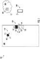
- FIG. 1 illustrates a first embodiment of the access control system 100 where the storage and processing of the access credentials are completed in the access control device 120.
- FIG. 2 illustrates a second embodiment of the access control system 100 where the storage and processing of the access credentials are completed in the camera 110.
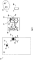
- FIG. 3 illustrates a third embodiment of the access control system 100 where the storage and processing of the access credentials are completed in the local processing device 130.
- the access credentials are stored and processed locally (e.g., not processed by a controller, which may be located up to 4000 feet (1200 metres) away from the access control device), which may help minimize any delay in granting access.
- the access control system 100 includes a camera 110 and an access control device 120.
- the access control system 100 further includes a local processing device 130.
- the local processing device 130 may, in certain instances, be any device within a short distance (e.g., less than ten feet (3 metres)) from the access control device 120 and the camera 110 that is capable of storing and processing access credentials.
- the camera 110, the access control device 120, and the local processing device 130 are configured as separate pieces of hardware (e.g., not constructed as one unit).
- the camera 110 may include an image sensor 111 and a communication module 112.
- the image sensor 111 may be configured to capture an optical image (e.g., of a face and/or an iris).
- the image sensor 111 may utilize any technology capable of detecting and conveying information regarding the optical image.
- the image sensor 111 may convey the optical image as a wireless signal (e.g., through one or more wired or wireless connections) to the communication module 112.
- the communication module 112 may be configured to wirelessly transmit the optical image using a short-range communication (e.g., Bluetooth, Bluetooth Low Energy (BTLE), Zigbee, infrared, and Wi-Fi) or transmit the optical image over a wired communication (e.g. UART, Serial, Fiber-optic, SPI or Ethernet cable).
- a short-range communication e.g., Bluetooth, Bluetooth Low Energy (BTLE), Zigbee, infrared, and Wi-Fi
- BTLE Bluetooth Low Energy
- Zigbee Zigbee
- infrared e.g., Bluetooth Low Energy (BTLE), Zigbee, infrared, and Wi-Fi
- BTLE Bluetooth Low Energy
- Wi-Fi Wireless Fidelity
- the access control device 120 may include a communication module 121, a storage medium 122, and an authentication module 123.
- the communication module 121 may be configured to receive the optical image from the communication module 112 of the camera 110 using the short-range and/or wired communication.
- the communication module 121 may be communicatively connected with the authentication module 123.
- the storage medium 122 may be configured to store a biometric identifier.
- the storage medium 122 may include, but it not limited to, any of the following: a hard disk, a random access memory (RAM), a read-only memory (ROM), an erasable programmable read-only memory (EPROM or Flash Memory), a static random access memory (SRAM), a portable compact disc read-only memory (CD-ROM), a digital versatile disk (DVD), a memory stick, and any suitable combination of the foregoing.
- the biometric identifiers stored in the storage medium 122 may be accessible by the authentication module 123.
- the authentication module 123 may be configured to compare the optical image with the biometric identifier.
- the authentication module 123 may include a processor to enable the comparison of the optical image with the biometric identifier.
- the processor may be, but is not limited to, a single-processor or multi-processor system of any of a wide array of possible architectures, including field programmable gate array (FPGA), a central processing unit (CPU), application specific integrated circuits (ASIC), digital signal processor (DSP) or graphics processing unit (GPU) hardware arranged homogenously or heterogeneously.
- FPGA field programmable gate array
- CPU central processing unit
- ASIC application specific integrated circuits
- DSP digital signal processor
- GPU graphics processing unit
- the authentication module 123 may also be capable of comparing access credentials received via conventional means (e.g., from an RFID card, a FOB, a card with a magnetic stripe, and/or a mobile device) with stored authorized access credentials (e.g., stored in the storage medium 122).
- the authentication module 123 may be operatively connected (e.g. through one or more wired or wireless connections) to a lock actuator 124.
- the lock actuator 124 may be configured to lock or unlock a mechanical or electronic lock when the access credentials are authenticated and not currently limited (e.g., not being used during a time of day where access rights not allowed).
- An optical image may be interpreted to be authenticated when the optical image captured by the camera matches a stored biometric identifier.
- Access credentials presented via conventional means may be interpreted to be authenticated when the presented access credential matches a stored authorized access credential.
- the biometric identifiers and any associated limitations may be transmitted from at least one of an external device 200 (e.g., mobile device, computing device, mobile tablet, etc.), a database 301, or a different access control device (not shown) to the access control device 120 for storage and/or processing of optical images.
- an external device 200 e.g., mobile device, computing device, mobile tablet, etc.
- a database 301 e.g., or a different access control device (not shown) to the access control device 120 for storage and/or processing of optical images.
- the transmission of the biometric identifier to the access control device 120 may be prompted by a check-in (e.g., either at a front desk of a hotel through a computing device or through a mobile app on a guest's mobile device).
- the database 301 in certain instances, is housed in the network 300 (e.g., the same network 300 as the access control system 100).
- the database 301 may be an external database (e.g., housed outside the network 300), such as CLEAR ® .
- the biometric identifier may be transmitted to the access control device 120 for storage and/or processing by being input into a mobile app or webpage using an external device 200 connected to the network 300.
- a guest of a hotel room may register one or more biometric identifiers in the mobile app, which may be transmitted and stored in the storage medium 122 (e.g., before the guest arrives at the hotel and/or the hotel room, or when the guest comes within Bluetooth range of the access control device 120).
- a guest's biometric identifier may be registered at the front desk (e.g., captured at the front desk and stored in the database 301), and may be transmitted to the access control device 120 before the guest arrives at the room.
- the biometric identifier may be on a separate item (e.g., on an RFID card) and transferred to the access control device 120.
- a guest may use a kiosk to load their biometric identifier on the RFID card.
- the biometric identifier may be added to the storage medium 122 by the authentication module 123.
- a biometric identifier may be added to the storage medium 122 when paired with at least one of an authenticated optical image and an authorized access credential (e.g., which may be presented using conventional means such as an RFID card, a FOB, a card with a magnetic stripe, and/or a mobile device).
- an authorized access credential e.g., which may be presented using conventional means such as an RFID card, a FOB, a card with a magnetic stripe, and/or a mobile device.
- a person may register a biometric identifier with the access control system 100 at the access control device 120 by presenting a separate item (e.g., an RFID card, a FOB, a card with a magnetic stripe, and/or a mobile device) with linked permissions, or by presenting an optical image that matches a stored biometric identifier.
- a separate item e.g., an RFID card, a FOB, a card with a magnetic stripe, and/or a mobile device
- an optical image that matches a stored biometric identifier.
- a primary guest whose biometric identifier (e.g., face and/or iris image) is already stored in the access control device 120 may be able to add a secondary guest's biometric identifier at the access control device 120.
- the presentation of authorized access credentials with a mobile device may be completed in a wireless close-range manner.
- the authorized access credentials may only be transmitted (e.g., by the mobile device) and/or authenticated (e.g., by the authentication module 123 of the access control device 120), to allow the addition of a biometric identifier (e.g., at the access control device 120 by the authentication module 123) once the mobile device is within a close proximity (e.g., within a few feet) of the access control device 120.
- the proximity may be calculated using any suitable technology and/or method (e.g., time of flight, signal strength, etc.).
- This requirement of close proximity may help (i) reduce battery consumption and (ii) ensure that a fast and secure connection is created between the mobile device and the access control device 120, which may help both to reduce processing time and prevent someone other than the intended person (e.g., preventing intruders) from being able to add a biometric identifier.
- the access control system 100 may further include the use of two-factor authentication (e.g., such as requiring a PIN code to be entered).
- this PIN code may be generated in the network 300 or the mobile device.
- a mobile device 100 e.g., registered to a guest
- the environment e.g., the hotel
- connects to the network 300 e.g., using Bluetooth, Wi-Fi, etc.
- a PIN code may be sent to the access control device 120 and/or the mobile device (e.g., if the PIN code is generated in the network 300).
- the PIN code may have to be entered (e.g., either in a mobile application on the mobile device or on the access control device 120) before the access control device 120 (e.g., the authentication module 123) allows a biometric identifier may be added.
- the mobile device may not transmit the access credentials, and/or the authentication module 123 may not process or acknowledge that the access credentials are authorized until the PIN code is entered.
- the entering of the PIN code may be time dependent (e.g., the user of the mobile device may have to enter the PIN code within a certain time interval of coming within a certain distance of the access control device 120). This requirement of another factor of authentication may add a layer of security so as to further ensure that only intended persons may be able to add biometric identifiers.
- the biometric identifier once added, may be transferred from a different access control device (not shown) to the access control device 120. This may be particularly advantageous in situations where one environment (e.g., hotel room, etc.) has multiple access control devices 120, or where one user (e.g., hotel guest, etc.) may have access to multiple different environments that each have their own access control devices 120.
- one environment e.g., hotel room, etc.
- one user e.g., hotel guest, etc.
- the access control system 100 described herein may allow registration to occur at only one access control device 120 (e.g., at the hotel room, pool, gym, etc.), which, once registered, is transmitted to other access control devices 120.
- the access control devices 120 may transmit biometric identifiers directly to one another (e.g., in a Bluetooth mesh configuration), or to the network 300, which then may transmit the biometric identifier to the access control devices 120.
- the network 300 may store (e.g., in the database 301) which access control devices 120 should grant access to a given user (e.g., a particular guest) and transmit registered biometric identifiers accordingly.
- the access control system 100 may be capable of capturing optical images when detecting door status events (e.g., vibration detection, motion detection, sound detection, infrared detection, rotation of a handle, and presentation of an access credential). This may help identify who accessed or tried to access the protected environment at any given time. For example, this may help identify an intruder who used a lost RFID card.
- the access control system 100 may include a detection sensor 125. This detection sensor 125 may be operably connected (e.g., through one or more wired or wireless connections) with the image sensor 111 (e.g., to initiate the capturing of the optical image when a door status event is detected).
- the detection sensor 125 may be located on the camera 110. It should be appreciated that the detection sensor 125 may include any technology (e.g., a passive infrared sensor, a radar motion sensor, and/or a capacitive sensor) capable of capturing door status events. For example, the detection sensor 125 may be capable of capturing at least one of the following: vibrations associated with a knock of the door 400, vibrations associated with the insertion of a key, movement associated with the opening or closing of the door 400, rotation of the handle, sound in proximity to the door 400, and heat caused by the presence of person or a fire in proximity to the door 400.
- any technology e.g., a passive infrared sensor, a radar motion sensor, and/or a capacitive sensor
- the detection sensor 125 may be capable of capturing at least one of the following: vibrations associated with a knock of the door 400, vibrations associated with the insertion of a key, movement associated with the opening or closing of the door 400, rotation of the handle, sound in proximity to
- the camera 110 may include an image sensor 111, a communication module 112, a storage medium 113, and an authentication module 114.
- the image sensor 111 may be configured to capture an optical image (e.g., of a face and/or an iris).
- the image sensor 111 may utilize any technology capable of detecting and conveying information regarding the optical image.
- the image sensor 111 may convey the optical image as a wireless signal (e.g., through one or more wired or wireless connections) to the authentication module 114.
- the storage medium 113 may be configured to store a biometric identifier.
- the storage medium 113 may include, but it not limited to, any of the following: a hard disk, a random access memory (RAM), a read-only memory (ROM), an erasable programmable read-only memory (EPROM or Flash Memory), a static random access memory (SRAM), a portable compact disc read-only memory (CD-ROM), a digital versatile disk (DVD), a memory stick, and any suitable combination of the foregoing.
- the biometric identifiers stored in the storage medium 113 may be accessible by the authentication module 114.
- the authentication module 114 may be configured to compare the optical image with the biometric identifier.
- the authentication module 114 may include a processor to enable the comparison of the optical image with the biometric identifier.
- the processor may be, but is not limited to, a single-processor or multi-processor system of any of a wide array of possible architectures, including field programmable gate array (FPGA), a central processing unit (CPU), application specific integrated circuits (ASIC), digital signal processor (DSP) or graphics processing unit (GPU) hardware arranged homogenously or heterogeneously.
- the authentication module 114 may generate an authentication signal when the optical image is authenticated and not currently limited (e.g., not being used during a time of day where access rights not allowed).
- the communication module 112 may be configured to wirelessly transmit the authentication signal using a short-range communication (e.g., Bluetooth, Bluetooth Low Energy (BTLE), Zigbee, infrared, and Wi-Fi) or transmit the authentication signal over a wired communication (e.g. UART, Serial, Fiber-optic, SPI or Ethernet cable).
- a short-range communication e.g., Bluetooth, Bluetooth Low Energy (BTLE), Zigbee, infrared, and Wi-Fi
- BTLE Bluetooth Low Energy
- Zigbee Zigbee
- infrared e.g., Bluetooth Low Energy (BTLE), Zigbee, infrared, and Wi-Fi
- a wired communication e.g. UART, Serial, Fiber-optic, SPI or Ethernet cable
- the access control device 120 may include a communication module 121 and a lock actuator 124.
- the communication module 121 may be configured to receive the authentication signal using the short-range and/or wired communication.
- the communication module 121 may be operatively connected (e.g., through one or more wired or wireless connections) to a lock actuator 124.
- the lock actuator 124 may be configured to lock or unlock a mechanical or electronic lock when the communication module 121 receives the authentication signal.
- the biometric identifiers may be transmitted from at least one of an external device 200 (e.g., mobile device, computing device, mobile tablet, etc.), a database 301, and a different access control device (not shown) to the camera 110 for storage and/or processing of optical images.
- an external device 200 e.g., mobile device, computing device, mobile tablet, etc.
- a database 301 e.g., a different access control device (not shown)
- each camera 110 may be linked with an access control device 120.
- the camera 110 and the access control device 120 each may be given unique device identifiers (e.g., to enable the camera 110 and the access control device 120 to know and trust one another).
- Each unique device identifier may consist of a unique numeric or alphanumeric code, and may be stored in the database 301 (e.g., the database 301 may store which particular unique device identifier, associated with a particular camera 110, is linked with which other particular unique device identifier, associated with a particular access control device 120). It is envisioned that at least a portion of a unique device identifier may be transmitted with the biometric identifier (e.g., the camera 110 may receive a portion of its own unique device identifier or a portion of a unique device identifier of a particular access control device 120 when receiving a biometric identifier). It should be appreciated that at least portion of a unique device identifier may be transmitted between the access control device 120 and the camera 110 when communicating.
- the camera 110 may transmit at least a portion of its own unique device identifier or at least a portion of an access control device's 120 unique device identifier to the access control device 120 when transmitting information (e.g., a biometric identifier and/or an optical image).
- information e.g., a biometric identifier and/or an optical image.
- the transmission of the biometric identifier to the camera 110 may be prompted by a check-in (e.g., either at a front desk of a hotel through a computing device or through a mobile app on a mobile device).
- the database 301 in certain instances, is housed in the network 300 (e.g., the same network 300 as the access control system 100). However, it is envisioned that the database 301, in certain instances, may be an external database (e.g., housed outside the network 300), such as CLEAR ® . In certain instances, the biometric identifier may be transmitted to the camera 110 for storage and/or processing by being input into a mobile app or webpage using an external device 200 connected to the network 300.
- a guest of a hotel room may register one or more biometric identifiers in the mobile app, which may be transmitted and stored in the storage medium 113 (e.g., before the guest arrives at the hotel and/or the hotel room, or when the guest comes within Bluetooth range of the access control device 120).
- a guest's biometric identifier may be registered at the front desk (e.g., captured at the front desk and stored in the database 301), and may be transmitted to the camera 110 (e.g., linked with a particular access control device 120 of a particular room) before the guest arrives at the room.
- the biometric identifier may be added to the storage medium 113 by the authentication module 114.
- a biometric identifier may be added to the storage medium 113 when paired with at least one of an authenticated optical image and an authorized access credential (e.g., which may be presented to the access control device 120 using conventional means such as an RFID card, a FOB, a card with a magnetic stripe, and/or a mobile device).
- an authorized access credential e.g., which may be presented to the access control device 120 using conventional means such as an RFID card, a FOB, a card with a magnetic stripe, and/or a mobile device.
- a person may register a biometric identifier with the access control system 100 at the camera 110 either (i) by presenting a separate item (e.g., an RFID card, a FOB, a card with a magnetic stripe, and/or a mobile device) with linked permissions (e.g., to the access control device 120), (ii) or by presenting an optical image that matches a stored biometric identifier (e.g., to the camera 110).
- a primary guest whose biometric identifier (e.g., face and/or iris image) is already stored in the camera 110 may be able to add a secondary guest at the camera 110.
- this embodiment may be capable of capturing optical images when detecting door status events (e.g., vibration detection, motion detection, sound detection, infrared detection, rotation of a handle, and presentation of an access credential). These optical images may be stored in the storage medium 113 of the camera 110.
- door status events e.g., vibration detection, motion detection, sound detection, infrared detection, rotation of a handle, and presentation of an access credential.
- At least one of the camera 110 and the access control device 120 may be battery powered. To increase the life of the battery, it may be advantageous to offload the storage and/or processing of the access credentials to a separate device (e.g., a local processing device 130), which may be powered by a wired connection.
- a separate device e.g., a local processing device 130
- the access credentials may be stored and processed in a local processing device 130 (e.g., located, at least partially, behind a light switch 500 within the protected environment).
- a light switch 500 it is envisioned that the local processing device 130 may be located anywhere where wired power is available (e.g., behind a light (not shown), or behind a key card switch (not shown)).
- a key card switch (not shown) is a device commonly used in Europe and Latin America to reduce energy consumption in a hotel room (e.g., by limiting the powering of the electronics within the room to only when a key card is placed within the key card switch).
- This placement of the local processing device 130 may provide benefits both in terms of added security and better communications. For example, by placing the local processing device 130 (which is storing and processing the biometric identifiers) within the protected environment (e.g., within the wall/ceiling, inside the room, behind the locked door 400 to the protected environment) it may be harder to break into the protected environment (as an attempted intruder may not be able to physically tamper with the local processing device 130). Additionally, with the light switch 500 typically being within a few feet of the door 400 (where the camera 110 and the access control device 120 may be positioned), there should be little to no delay in transmitting data between the local processing device 130 and the camera 110 or between the local processing device 130 and the access control device 120. It should be appreciated that the wired power connection may also result in a better (e.g., stronger) signal being emitted from the local processing device 130, which may allow better communication to the network 300, the external device 200, and/or within the access control system 100.
- the camera 110 when including a local processing device 130, may include an image sensor 111, and a communication module 112.
- the image sensor 111 may be configured to capture an optical image (e.g., of a face and/or an iris).
- the image sensor 111 may utilize any technology capable of detecting and conveying information regarding the optical image.
- the communication module 112 may be configured to wirelessly transmit the optical image (e.g., as a wireless signal) using a short-range communication (e.g., such as Bluetooth, Bluetooth Low Energy (BTLE), Zigbee, infrared, and/or Wi-Fi) to the local processing device 130.
- the local processing device 130 may include a communication module 131, a storage medium 132, and an authentication module 133.
- the communication module 131 is configured to receive the optical image using the short-range communication (e.g., from the communication module 112 of the camera 110).
- the storage medium 132 is configured to store a biometric identifier (e.g., received from at least one of an external device 200 and a database 301).
- the storage medium 132 may include, but it not limited to, any of the following: a hard disk, a random access memory (RAM), a read-only memory (ROM), an erasable programmable read-only memory (EPROM or Flash Memory), a static random access memory (SRAM), a portable compact disc read-only memory (CD-ROM), a digital versatile disk (DVD), a memory stick, and any suitable combination of the foregoing.
- the biometric identifiers stored in the storage medium 132 may be accessible by the authentication module 133.
- the authentication module 133 may be configured to compare the optical image with the stored biometric identifiers.
- the authentication module 133 may include a processor to enable the comparison of the optical image with the biometric identifier.
- the processor may be, but is not limited to, a single-processor or multi-processor system of any of a wide array of possible architectures, including field programmable gate array (FPGA), a central processing unit (CPU), application specific integrated circuits (ASIC), digital signal processor (DSP) or graphics processing unit (GPU) hardware arranged homogenously or heterogeneously.
- the authentication module 133 may generate an authentication signal when the optical image is authenticated and not currently limited (e.g., not being used during a time of day where access rights not allowed).
- the communication module 131 may be configured to wirelessly transmit the authentication signal using a short-range communication (e.g., Bluetooth, Bluetooth Low Energy (BTLE), Zigbee, infrared, and Wi-Fi) or transmit the authentication signal over a wired communication (e.g. UART, Serial, Fiber-optic, SPI or Ethernet cable) to the access control device 120.
- a short-range communication e.g., Bluetooth, Bluetooth Low Energy (BTLE), Zigbee, infrared, and Wi-Fi
- the access control device 120 may include a communication module 121 and a lock actuator 124.
- the communication module 121 may be configured to receive the authentication signal (e.g., from the communication module 131 of the local processing device 130) using the short-range and/or wired communication.
- the communication module 121 may be operatively connected (e.g., through one or more wired or wireless connections) to a lock actuator 124.
- the lock actuator 124 may be configured to lock or unlock a mechanical or electronic lock when the communication module 121 receives the authentication signal.
- each local processing device 130 may be connected to numerous (e.g., two or more) access control systems 100 (e.g., each of which include a camera 110 and an access control device 120).
- each local processing device 130 may be configured to receive at least a portion of a unique device identifier (e.g., which may identify the particular access control system 100, camera 110, and/or access control device 120 of which the data is associated with) when receiving the optical image (e.g., from the camera 110) and/or the biometric identifier. At least a portion of this unique device identifier may be transmitted from the local processing device 130 when transmitting the authentication signal to the access control device 120. This may enable the access control device 120 to trust the authentication signal.
- the unique device identifier(s) may be stored in the database 301 (e.g., housed in the same network 300 as the access control system 100).
- the biometric identifier may be sourced from an external database (e.g., housed outside the network 300), such as CLEAR ® , or may be transmitted to the local processing device 130 for storage and/or processing by being input into a mobile app or webpage using an external device 200 connected to the network 300.
- an external database e.g., housed outside the network 300
- CLEAR ® may be transmitted to the local processing device 130 for storage and/or processing by being input into a mobile app or webpage using an external device 200 connected to the network 300.
- a guest of a hotel room may register one or more biometric identifiers in the mobile app, which may be transmitted to the communication module 131 and stored in the storage medium 132 (e.g., before the guest arrives at the hotel and/or the hotel room, or when the guest comes within Bluetooth range of the local processing device 130).
- a guest's biometric identifier may be registered at the front desk (e.g., captured at the front desk and stored in the database 301), and may be transmitted to the communication module 131 of the local processing device 130 (e.g., associated with a particular access control system 100 of a particular room) before the guest arrives at the room.
- the communication module 131 of the local processing device 130 e.g., associated with a particular access control system 100 of a particular room
- the authentication module 133 in this embodiment may be configured to add biometric identifiers to the storage medium 132.
- a biometric identifier may be added to the storage medium 132 when paired with at least one of an authenticated optical image and an authorized access credential (e.g., which may be presented to the access control device 120 using conventional means such as an RFID card, a FOB, a card with a magnetic stripe, and/or a mobile device).
- a person may register a biometric identifier with the access control system 100 at the camera 110 either (i) by presenting a separate item (e.g., an RFID card, a FOB, a card with a magnetic stripe, and/or a mobile device) with linked permissions (e.g., to the access control device 120), (ii) or by presenting an optical image that matches a stored biometric identifier (e.g., to the camera 110).
- a primary guest whose biometric identifier (e.g., face and/or iris image) is already stored in the camera 110 may be able to add a secondary guest at the camera 110.
- this embodiment may be capable of capturing optical images when detecting door status events (e.g., vibration detection, motion detection, sound detection, infrared detection, rotation of a handle, and presentation of an access credential).
- detection sensor 125 e.g., a passive infrared sensor, a radar motion sensor, and/or a capacitive sensor
- the image sensor 111 e.g., to initiate the capturing of the optical image when a door status event is detected.
- it may be advantageous e.g., in one or more of the embodiments described) to put a visual indicator (not shown) on or near the camera 110.
- This visual indicator may cause a behavioral change (e.g., causing the person who caused the door status event to look at the camera 110), which may optimize the ability of the camera 110 to take an optical image that is capable of being processed.
- the visual indicator may be in the form of a light (e.g., an LED).
- the light may blink at or near the camera 110 when the detection sensor 125 detects a door status event.
- the visual indicator may serve an additional purpose of providing feedback to the user.
- the light may blink in a certain pattern or be of a certain color when capturing the optical image, and switch to a different pattern or different color when the captured optical image is being processed.
- the visual indicator may switch back to the pattern/color that indicates another optical image is being captured, which may let the user know that they need to look at the camera 110 to capture another optical image. It is envisioned that by providing feedback in this manner the user may feel more connected and informed and be willing to tolerate a longer latency period (e.g., caused by the processing of the optical image) than may otherwise be tolerated without feedback.
- the access control system 100 may, in certain instances, rely on one or more battery to power at least one of the camera 110 and the access control device 120.
- the local processing device 130 may be powered by a wired connection.
- the communication modules 112, 121, 131 may be used to "wake-up" the sleeping component(s). For example, if the camera 110 is configured to sleep, the communication module 121 of the access control device 120 may transmit a "wake-up" signal to the communication module 112 of the camera 110. Conversely, if the access control device 120 is configured to sleep, the communication module 112 of the camera 110 may transmit a "wake-up" signal to the communication module 121 of the access control device 120.
- the communication module 131 of the local processing device 130 may transmit a "wake-up" signal to the communication modules 112, 121 of both the camera 110 and the access control device 120.
- the "wake-up" signal may be transmitted using a short-range communication (e.g., Bluetooth, Bluetooth Low Energy (BTLE), Zigbee, infrared, and Wi-Fi) or over a wired communication (e.g. UART, Serial, Fiber-optic, SPI or Ethernet cable).
- the prompting of the "wake-up" signal may, in certain instances, be caused by a detection of a door status event by the detection sensor 125 (e.g., which may be configured to remain powered). It should be appreciated that in certain instances both the access control device 120 and the camera 110 are always on (e.g., meaning that neither are configured to "sleep").
- the camera 110, the access control device 120, and the local processing device 130 are configured as separate components (e.g., independent pieces of hardware) of the access control system 100.
- the access control system 100 may allow for a tiered access control system 100.
- at least one of the embodiments of the access control system 100 described herein may be capable of being implemented alongside existing systems by installing the camera 110 within the peephole 401 of the door 400, and configuring the existing access control device 120 to be capable of operating based on input (e.g., unlocking when receiving authentication signals) from the camera 110 and/or the local processing device 130. This may provide added flexibility and reduced cost for the customer (e.g., the hotel, hospital, office building, etc.).
- the access control system 100 described herein may be useful in a variety of different settings.
- the access control system 100 may be useful in any type of environment where access needs to be verified and/or recorded.
- the access control system 100 may be useful to ensure accuracy of records for who accessed a particular environment at a given time (e.g., who pulled medicine in a hospital setting, who accessed a hotel room at a given time, who requested the elevator at a given time).
- the access control system 100 when connected to a network 300, the access control system 100 may be capable of identifying a wandering intruder and be able to restrict access based on the stored biometric identifier.
- the access control system 100 may be capable of generating a wandering intruder identifier, which may be in the form of a biometric identifier that, instead of being used to grant access, is used to deny access.
- FIG. 4 An exemplary method 800 of operating an access control system 100 is illustrated in FIG. 4 .
- the method 800 may be performed, for example, using any of the exemplary access control systems 100 shown in FIGs. 1-3 , which include a camera 110 and an access control device 120 (in all embodiments), and a local processing device 130 (in at least one embodiment).
- the method 800 includes step 810 for storing a biometric identifier in a storage medium (e.g., which may be in the camera 110, the access control device 120, or the local processing device 130 (when included)).
- the method 800 includes step 820 for capturing an optical image with an image sensor 111 of the camera.
- the capturing of the optical image with an image sensor 111 may be initiated by the detection of a door status event with the detection sensor 125.
- the method 800 includes step 830 for comparing, in an authentication module (e.g., which may be in the camera 110, the access control device 120, or the local processing device 130 (when included)), the optical image with the biometric identifier.
- an authentication module e.g., which may be in the camera 110, the access control device 120, or the local processing device 130 (when included)
- the method 800 may provide for the transmitting of the optical image to at least one of a network 300 and an external device 200.
- additional information such as the event type (e.g., a failure of opening or a successful opening), the time the event occurred, and/or an identifier (e.g., a name associated with a given access credential, as opposed to an optical image) may be transmitted (either alone or with the optical image) to at least one of the network 300 and the external device 200.
- the optical image and/or the additional information may be stored as a record in the database 301 (e.g., housed in the network 300), and may be accessible for later use. For example, the record may make it possible to identify who attempted to or gained access to a particular protected environment at a given time. This information may also be able to help prevent future intrusions.
- each access control system 100 may be connected to a network 300.
- the network 300 may include at least two access control systems 100.
- the network 300 may be configured to generate a wandering intruder identifier (e.g., a biometric identifier to be blocked). This wandering intruder identifier may be generated by the network 300 following the repeated use and/or failure of an access credential at one or more access control systems 100.
- an access control system 100 may communicate a failed access attempt to the network 300.
- the network 300 may be configured to recognize a pattern of repeated uses and/or failures and generate a wandering intruder identifier. It should be appreciated that a pattern of repeated uses and/or failures may be recognized when the same access credentials are denied by two or more access control systems 100.
- the wandering intruder identifier may be transmitted to at least one access control system 100 within the network 300.
- the network 300 may be configured to transmit the wandering intruder identifier to all of the access control systems 100 within the network 300. As mentioned above, this may allow the access control system 100 to deny access when a captured optical image matches a wandering intruder identifier.
Abstract
Description
- Access control devices (e.g., access control readers, lockboxes, and hotel locks) can be used to control various types of protected environments. Access control readers can be used to regulate the entry into and movement within a building. Lockboxes can be used to control the access to one or more items inside the lockbox (e.g., a key for a door to a home). Hotel locks can be used to limit access to a hotel room. To access the protected environment, authorized access credentials must be presented (e.g., to the access control device).
- Conventionally, credentials have been presented to the access control devices using an RFID card, a FOB, a card with a magnetic stripe, and/or a mobile device. The decision of whether to grant access (e.g., by unlocking) is typically processed at a controller (e.g., located up to 4000 feet (1200 metres) away from the access control device). For example, the controller may check a permissions database to ascertain whether there is a permission linked to the requestor's access credential. However, the conventional means of presenting credentials have the potential to be used by anyone (e.g., someone other than who they are intended to be used by). For example, in a hotel setting, a person may find a key card and may be able to access a room even though they are not the intended guest of the room. This may present a security issue both for the intended guest and for the hotel, as the person may remove or damage items within the room owned by either the intended guest or the hotel. Additionally, with conventional access control devices the identity of the person presenting the credentials is never captured, which may make it difficult to catch an intruder.
- To ensure that access is not granted to an unintended person (e.g., an intruder) access control devices with biometric authentication have been deployed. Such devices verify the identity of a person based on a physiological or behavioral characteristic (e.g., by capturing an optical image of a biometric identifier, such as a fingerprint, a facial image, and/or an iris scan). These devices typically require connection to a network in order to match the presented biometric identifier with a stored, authorized biometric identifier. For example, the access control device may be capable of capturing the biometric identifier (e.g., by scanning a fingerprint, or taking a picture), but the processing of the biometric identifier (e.g., to see whether the biometric identifier matches an authorized biometric identifier) is typically done remotely (e.g., outside of the access control device, in a controller, which, as mentioned, may be located up to 4000 feet (1200 metres) away from the access control device). One downside of using remote processing is the potential for delay in granting access. This delay may be caused by the time required for transmitting the signal(s) (e.g., between the access control device and the distant controller).
- Accordingly, there remains a need for an access control system that is capable of capturing and locally processing biometric identifiers.
- According to one aspect an access control system with a camera and an access control device is provided. The camera includes an image sensor and a communication module. The image sensor is configured to capture an optical image. The communication module is configured to wirelessly transmit the optical image using a short-range communication. The access control device includes a communication module, a storage medium, and an authentication module. The communication module is configured to receive the optical image using the short-range communication. The storage medium is configured to store a biometric identifier. The authentication module is configured to compare the optical image with the biometric identifier. The authentication module is operatively connected to a lock actuator. The lock actuator is configured to lock or unlock a mechanical or electronic lock when the optical image is authenticated.
- Optionally, the biometric identifier is transmitted from at least one of an external device, a database, and a different access control device.
- Optionally, the authentication module is configured to add at least one biometric identifier to the storage medium.
- Optionally, the biometric identifier is added to the storage medium when paired with at least one of an authenticated optical image and an authorized access credential.
- Optionally, a detection sensor operably connected to the image sensor is provided, the detection sensor is configured to initiate the capturing of the optical image when a door status event is detected.
- Optionally, the door status event includes at least one of: a vibration detection, a motion detection, a sound detection, an infrared detection, a rotation of a handle, and a presentation of an access credential.
- Optionally, the short-range communication includes at least one of: Bluetooth, Bluetooth Low Energy (BTLE), Zigbee, infrared, and Wi-Fi.
- Optionally, the camera is located, at least partially, within a peephole of a door.
- Optionally, at least one of the camera and the access control device are battery powered.
- According to another aspect, an access control system including a camera and an access control device is provided. The camera includes an image sensor, a storage medium, an authentication module, and a communication module. The image sensor is configured to capture an optical image. The storage medium is configured to store a biometric identifier. The authentication module is configured to compare the optical image with the biometric identifier. The authentication module is configured to generate an authentication signal when the optical image is authenticated. The communication module is configured to wirelessly transmit the authentication signal using a short-range communication. The access control device includes a communication module and a lock actuator. The communication module is configured to receive the authentication signal using the short-range communication. The lock actuator is operatively connected to the communication module. The lock actuator is configured to lock or unlock a mechanical or electronic lock when the communication module receives the authentication signal.
- Optionally, the biometric identifier is transmitted from at least one of an external device, a database, and a different access control device.
- Optionally, the authentication module is configured to add at least one biometric identifier to the storage medium.
- Optionally, the biometric identifier is added to the storage medium when paired with at least one of an authenticated optical image and an authorized access credential.
- Optionally, a detection sensor operably connected to the image sensor is provided, the detection sensor is configured to initiate the capturing of the optical image when a door status event is detected.
- Optionally, the door status event includes at least one of: a vibration detection, a motion detection, a sound detection, an infrared detection, a rotation of a handle, and a presentation of an access credential.
- Optionally, the short-range communication includes at least one of: Bluetooth, Bluetooth Low Energy (BTLE), Zigbee, infrared, and Wi-Fi.
- Optionally, the camera is located, at least partially, within a peephole of a door.
- Optionally, at least one of the camera and the access control device are battery powered.
- According to another aspect, an access control system including a camera, a local processing device, and an access control device is provided. The camera includes an image sensor and a communication module. The image sensor is configured to capture an optical image. The communication module is configured to wirelessly transmit the optical image using a short-range communication. The local processing device includes a communication module, a storage medium, and an authentication module. The communication module is configured to receive the optical image using the short-range communication. The storage medium is configured to store a biometric identifier. The authentication module is configured to compare the optical image with the biometric identifier. The authentication module is configured to generate an authentication signal when the optical image is authenticated. The access control device includes a communication module and a lock actuator. The communication module is configured to receive the authentication signal using the short-range communication. The lock actuator is operatively connected to the communication module. The lock actuator is configured to lock or unlock a mechanical or electronic lock when the communication module receives the authentication signal.
- Optionally, the biometric identifier is transmitted from at least one of an external device, a database, and a different access control device.
- Optionally, the authentication module is configured to add at least one biometric identifier to the storage medium.
- Optionally, the biometric identifier is added to the storage medium when paired with at least one of an authenticated optical image and an authorized access credential.
- Optionally, a detection sensor is operably connected to the image sensor, the detection sensor configured to initiate the capturing of the optical image when a door status event is detected.
- Optionally, the door status event includes at least one of: a vibration detection, a motion detection, a sound detection, an infrared detection, a rotation of a handle, and a presentation of an access credential.
- Optionally, the short-range communication includes at least one of: Bluetooth, Bluetooth Low Energy (BTLE), Zigbee, infrared, and Wi-Fi.
- Optionally, the local processing device is located, at least partially, behind a light switch.
- Optionally, at least one of the camera and the access control device are battery powered, and the local processing device is powered by a wired connection.
- According to another aspect, a method for operating an access control system including a camera and an access control device is provided. The method includes a step for storing a biometric identifier in a storage medium, at least one of the camera, the access control device, and a local processing device including the storage medium. The method includes a step for capturing an optical image with an image sensor of the camera. The method includes a step for comparing, in an authentication module, the optical image with the biometric identifier, at least one of the camera, the access control device, and the local processing device including the authentication module, wherein a lock actuator is configured to unlock a mechanical or electronic lock when the optical image matches the biometric identifier.
- Optionally, the local processing device includes the storage medium and the authentication module.
- Optionally, the camera includes the storage medium and the authentication module.
- Optionally, the access control device includes the storage medium and the authentication module.
- Optionally, the method provides a step for transmitting the optical image to at least one of a network including at least two access control systems, and an external device.
- Optionally, the network is configured to generate a wandering intruder identifier when a pattern of repeated uses and/or failures is recognized.
- Optionally, the method provides a step for transmitting the wandering intruder identifier to at least one access control system within the network, the at least one access control system configured to use the wandering intruder identifier to deny access.
- Certain exemplary embodiments will now be described in greater detail by way of example only and with reference to the accompanying drawings. The following descriptions of the drawings should not be considered limiting in any way. With reference to the accompanying drawings, like elements are numbered alike.
-
FIG. 1 is a schematic illustration of a first access control system with a camera and an access control device. -
FIG. 2 is a schematic illustration of a second access control system with a camera and an access control device. -
FIG. 3 is a schematic illustration of a third access control system with a camera, an access control device, and a local processing device. -
FIG. 4 is a flow diagram illustrating a method of operating an access control system including a camera and an access control device. - Access control devices (e.g., access control readers, lockboxes, and hotel locks) may grant or deny access to a particular environment based on whether or not authorized credentials are received. The credentials may be transmitted with a separate item (e.g., an RFID card, a FOB, a card with a magnetic stripe, and/or a mobile device) or by presenting a biometric identifier (e.g., a fingerprint, face, and/or iris). When using a separate item, the credentials may be transmitted directly to the access control device. When presenting a biometric identifier, the credentials may be captured by a camera (e.g., by taking an optical image). It should be appreciated that the access control system described herein includes a camera and an access control device (in all embodiments), and a local processing device (in at least one embodiment). The camera, access control device, and the local processing device (when included) each are to be interpreted as separate pieces of hardware (e.g., not configured together). For example, the camera may be incorporated within a peephole of a door, the access control device may be incorporated within the door lock, and the local processing device may be incorporated inside the protected environment (e.g., behind a light switch).
- Regardless of how presented, the credentials may be compared to the stored, authorized access credentials to see whether there is a permission linked to the requester's access credential. It is envisioned that the authorized access credentials are stored locally in a storage medium (e.g., in the camera, in the access control device, or in the local processing device (when included)). In certain instances, the authorized access credentials may have limited access rights. For example, particular access credentials may be associated with limited access rights that limit when the person is allowed access (or when they are not allowed access) depending on the time of day, etc. It should be appreciated that the authorized access credentials may be updated periodically. For example, the biometric identifiers may be updated (e.g., deleted and/or removed from the storage medium in the camera, in the access control device, or in the local processing device (when included)) when the access rights of a person expire (e.g., when the person should no longer have access to the particular environment). For example, when a guest checks out of a hotel their biometric identifier may be deleted/removed from the storage medium or may be switched from 'grant access' to 'deny access'. It should be appreciated that although described herein to be particularly useful in deciding when to grant access, in certain instances the capturing and processing of a biometric identifier may also be useful in deciding when to deny access.
- Each access control device and/or local processing device (when included) may be connected to a controller, and each controller may be connected to a network (e.g., using a gateway, such as a router). The network may contain one or more databases maintained at a central server (e.g., which may be either on-site and/or cloud-based) and relevant parts (e.g., the updated list of authorized access credentials) of the databases may be downloaded to individual controllers. The controllers may communicate the authorized access credentials and any associated limitations or expirations of the authorized access credentials to the access control devices for storage and later processing (e.g., by an authentication module in the camera, the access control device, or the local processing device). In certain instances, individual access control devices and/or local processing devices (when included) may be connected directly to the network (e.g., without using a controller), and/or may receive authorized access credentials (e.g., which may be in the form of a stored biometric identifiers) and any associated limitations or expirations of the authorized access credentials from an external device (e.g., mobile device, computing device, mobile tablet, etc.) and/or a different access control device. For example, an authorized access credential may be added directly at an access control device by being paired with at least one of an authenticated optical image and an authorized access credential (e.g., transmitted with a separate item, such as an RFID card, a FOB, a card with a magnetic strip, and/or a mobile device), or indirectly by being added at a different access control device (described below). It is envisioned that by locally storing and processing the access credentials, the delay in granting access may be minimized (especially when the network connection is slow or has a long latency).
- With reference now to the Figures, various schematic illustrations of an
access control system 100 are shown inFIGs. 1-3 .FIG. 1 illustrates a first embodiment of theaccess control system 100 where the storage and processing of the access credentials are completed in theaccess control device 120.FIG. 2 illustrates a second embodiment of theaccess control system 100 where the storage and processing of the access credentials are completed in thecamera 110.FIG. 3 illustrates a third embodiment of theaccess control system 100 where the storage and processing of the access credentials are completed in thelocal processing device 130. Regardless of the embodiment, the access credentials are stored and processed locally (e.g., not processed by a controller, which may be located up to 4000 feet (1200 metres) away from the access control device), which may help minimize any delay in granting access. In each embodiment, theaccess control system 100 includes acamera 110 and anaccess control device 120. In at least one embodiment, theaccess control system 100 further includes alocal processing device 130. It should be appreciated that thelocal processing device 130 may, in certain instances, be any device within a short distance (e.g., less than ten feet (3 metres)) from theaccess control device 120 and thecamera 110 that is capable of storing and processing access credentials. As mentioned above, thecamera 110, theaccess control device 120, and thelocal processing device 130 are configured as separate pieces of hardware (e.g., not constructed as one unit). - As depicted in
FIG. 1 , where the access credentials are stored and processed in theaccess control device 120, thecamera 110 may include animage sensor 111 and acommunication module 112. Theimage sensor 111 may be configured to capture an optical image (e.g., of a face and/or an iris). Theimage sensor 111 may utilize any technology capable of detecting and conveying information regarding the optical image. For example, theimage sensor 111 may convey the optical image as a wireless signal (e.g., through one or more wired or wireless connections) to thecommunication module 112. Thecommunication module 112 may be configured to wirelessly transmit the optical image using a short-range communication (e.g., Bluetooth, Bluetooth Low Energy (BTLE), Zigbee, infrared, and Wi-Fi) or transmit the optical image over a wired communication (e.g. UART, Serial, Fiber-optic, SPI or Ethernet cable). - The
access control device 120 may include acommunication module 121, astorage medium 122, and anauthentication module 123. Thecommunication module 121 may be configured to receive the optical image from thecommunication module 112 of thecamera 110 using the short-range and/or wired communication. Thecommunication module 121 may be communicatively connected with theauthentication module 123. Thestorage medium 122 may be configured to store a biometric identifier. Thestorage medium 122 may include, but it not limited to, any of the following: a hard disk, a random access memory (RAM), a read-only memory (ROM), an erasable programmable read-only memory (EPROM or Flash Memory), a static random access memory (SRAM), a portable compact disc read-only memory (CD-ROM), a digital versatile disk (DVD), a memory stick, and any suitable combination of the foregoing. The biometric identifiers stored in thestorage medium 122 may be accessible by theauthentication module 123. - The
authentication module 123 may be configured to compare the optical image with the biometric identifier. Theauthentication module 123 may include a processor to enable the comparison of the optical image with the biometric identifier. The processor may be, but is not limited to, a single-processor or multi-processor system of any of a wide array of possible architectures, including field programmable gate array (FPGA), a central processing unit (CPU), application specific integrated circuits (ASIC), digital signal processor (DSP) or graphics processing unit (GPU) hardware arranged homogenously or heterogeneously. It should be appreciated that theauthentication module 123 may also be capable of comparing access credentials received via conventional means (e.g., from an RFID card, a FOB, a card with a magnetic stripe, and/or a mobile device) with stored authorized access credentials (e.g., stored in the storage medium 122). Theauthentication module 123 may be operatively connected (e.g. through one or more wired or wireless connections) to alock actuator 124. Thelock actuator 124 may be configured to lock or unlock a mechanical or electronic lock when the access credentials are authenticated and not currently limited (e.g., not being used during a time of day where access rights not allowed). An optical image may be interpreted to be authenticated when the optical image captured by the camera matches a stored biometric identifier. Access credentials presented via conventional means may be interpreted to be authenticated when the presented access credential matches a stored authorized access credential. - The biometric identifiers and any associated limitations may be transmitted from at least one of an external device 200 (e.g., mobile device, computing device, mobile tablet, etc.), a
database 301, or a different access control device (not shown) to theaccess control device 120 for storage and/or processing of optical images. In certain instances, the transmission of the biometric identifier to theaccess control device 120 may be prompted by a check-in (e.g., either at a front desk of a hotel through a computing device or through a mobile app on a guest's mobile device). Thedatabase 301, in certain instances, is housed in the network 300 (e.g., thesame network 300 as the access control system 100). However, it is envisioned that thedatabase 301, in certain instances, may be an external database (e.g., housed outside the network 300), such as CLEAR®. In certain instances, the biometric identifier may be transmitted to theaccess control device 120 for storage and/or processing by being input into a mobile app or webpage using anexternal device 200 connected to thenetwork 300. For example, a guest of a hotel room may register one or more biometric identifiers in the mobile app, which may be transmitted and stored in the storage medium 122 (e.g., before the guest arrives at the hotel and/or the hotel room, or when the guest comes within Bluetooth range of the access control device 120). Additionally, it is envisioned that a guest's biometric identifier may be registered at the front desk (e.g., captured at the front desk and stored in the database 301), and may be transmitted to theaccess control device 120 before the guest arrives at the room. In certain instances, the biometric identifier may be on a separate item (e.g., on an RFID card) and transferred to theaccess control device 120. For example, a guest may use a kiosk to load their biometric identifier on the RFID card. - The biometric identifier may be added to the
storage medium 122 by theauthentication module 123. For example, a biometric identifier may be added to thestorage medium 122 when paired with at least one of an authenticated optical image and an authorized access credential (e.g., which may be presented using conventional means such as an RFID card, a FOB, a card with a magnetic stripe, and/or a mobile device). It is envisioned that a person may register a biometric identifier with theaccess control system 100 at theaccess control device 120 by presenting a separate item (e.g., an RFID card, a FOB, a card with a magnetic stripe, and/or a mobile device) with linked permissions, or by presenting an optical image that matches a stored biometric identifier. For example, a primary guest whose biometric identifier (e.g., face and/or iris image) is already stored in theaccess control device 120 may be able to add a secondary guest's biometric identifier at theaccess control device 120. - The presentation of authorized access credentials with a mobile device (e.g., to enable the adding of a biometric identifier) may be completed in a wireless close-range manner. For example, the authorized access credentials may only be transmitted (e.g., by the mobile device) and/or authenticated (e.g., by the
authentication module 123 of the access control device 120), to allow the addition of a biometric identifier (e.g., at theaccess control device 120 by the authentication module 123) once the mobile device is within a close proximity (e.g., within a few feet) of theaccess control device 120. The proximity may be calculated using any suitable technology and/or method (e.g., time of flight, signal strength, etc.). This requirement of close proximity (when included) may help (i) reduce battery consumption and (ii) ensure that a fast and secure connection is created between the mobile device and theaccess control device 120, which may help both to reduce processing time and prevent someone other than the intended person (e.g., preventing intruders) from being able to add a biometric identifier. - For added security, the
access control system 100 may further include the use of two-factor authentication (e.g., such as requiring a PIN code to be entered). It should be appreciated that this PIN code may be generated in thenetwork 300 or the mobile device. For example, when a mobile device 100 (e.g., registered to a guest) enters the environment (e.g., the hotel) and connects to the network 300 (e.g., using Bluetooth, Wi-Fi, etc.), a PIN code may be sent to theaccess control device 120 and/or the mobile device (e.g., if the PIN code is generated in the network 300). Once the mobile device is within close proximity of theaccess control device 120 the PIN code may have to be entered (e.g., either in a mobile application on the mobile device or on the access control device 120) before the access control device 120 (e.g., the authentication module 123) allows a biometric identifier may be added. For example, the mobile device may not transmit the access credentials, and/or theauthentication module 123 may not process or acknowledge that the access credentials are authorized until the PIN code is entered. It is envisioned that the entering of the PIN code may be time dependent (e.g., the user of the mobile device may have to enter the PIN code within a certain time interval of coming within a certain distance of the access control device 120). This requirement of another factor of authentication may add a layer of security so as to further ensure that only intended persons may be able to add biometric identifiers. - As mentioned above, the biometric identifier, once added, may be transferred from a different access control device (not shown) to the
access control device 120. This may be particularly advantageous in situations where one environment (e.g., hotel room, etc.) has multipleaccess control devices 120, or where one user (e.g., hotel guest, etc.) may have access to multiple different environments that each have their ownaccess control devices 120. For example, instead of requiring the guest to register their biometric identifier at theaccess control device 120 to their hotel room and theaccess control devices 120 for the shared spaces (e.g., the hotel pool or the gym), theaccess control system 100 described herein may allow registration to occur at only one access control device 120 (e.g., at the hotel room, pool, gym, etc.), which, once registered, is transmitted to otheraccess control devices 120. It should be appreciated that theaccess control devices 120 may transmit biometric identifiers directly to one another (e.g., in a Bluetooth mesh configuration), or to thenetwork 300, which then may transmit the biometric identifier to theaccess control devices 120. For example, thenetwork 300 may store (e.g., in the database 301) whichaccess control devices 120 should grant access to a given user (e.g., a particular guest) and transmit registered biometric identifiers accordingly. - In certain instances, the
access control system 100 may be capable of capturing optical images when detecting door status events (e.g., vibration detection, motion detection, sound detection, infrared detection, rotation of a handle, and presentation of an access credential). This may help identify who accessed or tried to access the protected environment at any given time. For example, this may help identify an intruder who used a lost RFID card. To detect the door status events, theaccess control system 100 may include adetection sensor 125. Thisdetection sensor 125 may be operably connected (e.g., through one or more wired or wireless connections) with the image sensor 111 (e.g., to initiate the capturing of the optical image when a door status event is detected). Although only depicting adetection sensor 125 on theaccess control device 120, it is envisioned that thedetection sensor 125 may be located on thecamera 110. It should be appreciated that thedetection sensor 125 may include any technology (e.g., a passive infrared sensor, a radar motion sensor, and/or a capacitive sensor) capable of capturing door status events. For example, thedetection sensor 125 may be capable of capturing at least one of the following: vibrations associated with a knock of thedoor 400, vibrations associated with the insertion of a key, movement associated with the opening or closing of thedoor 400, rotation of the handle, sound in proximity to thedoor 400, and heat caused by the presence of person or a fire in proximity to thedoor 400. - As depicted in
FIG. 2 , where the access credentials are stored and processed in thecamera 110, thecamera 110 may include animage sensor 111, acommunication module 112, astorage medium 113, and anauthentication module 114. Theimage sensor 111 may be configured to capture an optical image (e.g., of a face and/or an iris). Theimage sensor 111 may utilize any technology capable of detecting and conveying information regarding the optical image. For example, theimage sensor 111 may convey the optical image as a wireless signal (e.g., through one or more wired or wireless connections) to theauthentication module 114. Thestorage medium 113 may be configured to store a biometric identifier. Thestorage medium 113 may include, but it not limited to, any of the following: a hard disk, a random access memory (RAM), a read-only memory (ROM), an erasable programmable read-only memory (EPROM or Flash Memory), a static random access memory (SRAM), a portable compact disc read-only memory (CD-ROM), a digital versatile disk (DVD), a memory stick, and any suitable combination of the foregoing. The biometric identifiers stored in thestorage medium 113 may be accessible by theauthentication module 114. - The
authentication module 114 may be configured to compare the optical image with the biometric identifier. Theauthentication module 114 may include a processor to enable the comparison of the optical image with the biometric identifier. The processor may be, but is not limited to, a single-processor or multi-processor system of any of a wide array of possible architectures, including field programmable gate array (FPGA), a central processing unit (CPU), application specific integrated circuits (ASIC), digital signal processor (DSP) or graphics processing unit (GPU) hardware arranged homogenously or heterogeneously. Theauthentication module 114 may generate an authentication signal when the optical image is authenticated and not currently limited (e.g., not being used during a time of day where access rights not allowed). Thecommunication module 112 may be configured to wirelessly transmit the authentication signal using a short-range communication (e.g., Bluetooth, Bluetooth Low Energy (BTLE), Zigbee, infrared, and Wi-Fi) or transmit the authentication signal over a wired communication (e.g. UART, Serial, Fiber-optic, SPI or Ethernet cable). - The
access control device 120 may include acommunication module 121 and alock actuator 124. Thecommunication module 121 may be configured to receive the authentication signal using the short-range and/or wired communication. Thecommunication module 121 may be operatively connected (e.g., through one or more wired or wireless connections) to alock actuator 124. Thelock actuator 124 may be configured to lock or unlock a mechanical or electronic lock when thecommunication module 121 receives the authentication signal. - The biometric identifiers may be transmitted from at least one of an external device 200 (e.g., mobile device, computing device, mobile tablet, etc.), a
database 301, and a different access control device (not shown) to thecamera 110 for storage and/or processing of optical images. To ensure that each biometric identifier is transmitted to the correct camera 110 (e.g., associated with a particular access control device 120), eachcamera 110 may be linked with anaccess control device 120. For example, thecamera 110 and theaccess control device 120 each may be given unique device identifiers (e.g., to enable thecamera 110 and theaccess control device 120 to know and trust one another). Each unique device identifier may consist of a unique numeric or alphanumeric code, and may be stored in the database 301 (e.g., thedatabase 301 may store which particular unique device identifier, associated with aparticular camera 110, is linked with which other particular unique device identifier, associated with a particular access control device 120). It is envisioned that at least a portion of a unique device identifier may be transmitted with the biometric identifier (e.g., thecamera 110 may receive a portion of its own unique device identifier or a portion of a unique device identifier of a particularaccess control device 120 when receiving a biometric identifier). It should be appreciated that at least portion of a unique device identifier may be transmitted between theaccess control device 120 and thecamera 110 when communicating. For example, thecamera 110 may transmit at least a portion of its own unique device identifier or at least a portion of an access control device's 120 unique device identifier to theaccess control device 120 when transmitting information (e.g., a biometric identifier and/or an optical image). In certain instances, the transmission of the biometric identifier to thecamera 110 may be prompted by a check-in (e.g., either at a front desk of a hotel through a computing device or through a mobile app on a mobile device). - The
database 301, in certain instances, is housed in the network 300 (e.g., thesame network 300 as the access control system 100). However, it is envisioned that thedatabase 301, in certain instances, may be an external database (e.g., housed outside the network 300), such as CLEAR®. In certain instances, the biometric identifier may be transmitted to thecamera 110 for storage and/or processing by being input into a mobile app or webpage using anexternal device 200 connected to thenetwork 300. For example, a guest of a hotel room may register one or more biometric identifiers in the mobile app, which may be transmitted and stored in the storage medium 113 (e.g., before the guest arrives at the hotel and/or the hotel room, or when the guest comes within Bluetooth range of the access control device 120). Additionally, it is envisioned that a guest's biometric identifier may be registered at the front desk (e.g., captured at the front desk and stored in the database 301), and may be transmitted to the camera 110 (e.g., linked with a particularaccess control device 120 of a particular room) before the guest arrives at the room. - The biometric identifier may be added to the
storage medium 113 by theauthentication module 114. For example, a biometric identifier may be added to thestorage medium 113 when paired with at least one of an authenticated optical image and an authorized access credential (e.g., which may be presented to theaccess control device 120 using conventional means such as an RFID card, a FOB, a card with a magnetic stripe, and/or a mobile device). It is envisioned that a person may register a biometric identifier with theaccess control system 100 at thecamera 110 either (i) by presenting a separate item (e.g., an RFID card, a FOB, a card with a magnetic stripe, and/or a mobile device) with linked permissions (e.g., to the access control device 120), (ii) or by presenting an optical image that matches a stored biometric identifier (e.g., to the camera 110). For example, a primary guest whose biometric identifier (e.g., face and/or iris image) is already stored in thecamera 110 may be able to add a secondary guest at thecamera 110. It should be appreciated that, as with the first embodiment (shown inFIG. 1 ), this embodiment (shown inFIG. 2 ) may be capable of capturing optical images when detecting door status events (e.g., vibration detection, motion detection, sound detection, infrared detection, rotation of a handle, and presentation of an access credential). These optical images may be stored in thestorage medium 113 of thecamera 110. - At least one of the
camera 110 and theaccess control device 120 may be battery powered. To increase the life of the battery, it may be advantageous to offload the storage and/or processing of the access credentials to a separate device (e.g., a local processing device 130), which may be powered by a wired connection. For example, as shown inFIG. 3 , the access credentials may be stored and processed in a local processing device 130 (e.g., located, at least partially, behind alight switch 500 within the protected environment). Although shown behind alight switch 500, it is envisioned that thelocal processing device 130 may be located anywhere where wired power is available (e.g., behind a light (not shown), or behind a key card switch (not shown)). A key card switch (not shown) is a device commonly used in Europe and Latin America to reduce energy consumption in a hotel room (e.g., by limiting the powering of the electronics within the room to only when a key card is placed within the key card switch). - This placement of the
local processing device 130 may provide benefits both in terms of added security and better communications. For example, by placing the local processing device 130 (which is storing and processing the biometric identifiers) within the protected environment (e.g., within the wall/ceiling, inside the room, behind the lockeddoor 400 to the protected environment) it may be harder to break into the protected environment (as an attempted intruder may not be able to physically tamper with the local processing device 130). Additionally, with thelight switch 500 typically being within a few feet of the door 400 (where thecamera 110 and theaccess control device 120 may be positioned), there should be little to no delay in transmitting data between thelocal processing device 130 and thecamera 110 or between thelocal processing device 130 and theaccess control device 120. It should be appreciated that the wired power connection may also result in a better (e.g., stronger) signal being emitted from thelocal processing device 130, which may allow better communication to thenetwork 300, theexternal device 200, and/or within theaccess control system 100. - As shown in
FIG. 3 , when including alocal processing device 130, thecamera 110 may include animage sensor 111, and acommunication module 112. Theimage sensor 111 may be configured to capture an optical image (e.g., of a face and/or an iris). Theimage sensor 111 may utilize any technology capable of detecting and conveying information regarding the optical image. Thecommunication module 112 may be configured to wirelessly transmit the optical image (e.g., as a wireless signal) using a short-range communication (e.g., such as Bluetooth, Bluetooth Low Energy (BTLE), Zigbee, infrared, and/or Wi-Fi) to thelocal processing device 130. Thelocal processing device 130 may include acommunication module 131, astorage medium 132, and anauthentication module 133. Thecommunication module 131 is configured to receive the optical image using the short-range communication (e.g., from thecommunication module 112 of the camera 110). Thestorage medium 132 is configured to store a biometric identifier (e.g., received from at least one of anexternal device 200 and a database 301). - The
storage medium 132 may include, but it not limited to, any of the following: a hard disk, a random access memory (RAM), a read-only memory (ROM), an erasable programmable read-only memory (EPROM or Flash Memory), a static random access memory (SRAM), a portable compact disc read-only memory (CD-ROM), a digital versatile disk (DVD), a memory stick, and any suitable combination of the foregoing. The biometric identifiers stored in thestorage medium 132 may be accessible by theauthentication module 133. Theauthentication module 133 may be configured to compare the optical image with the stored biometric identifiers. Theauthentication module 133 may include a processor to enable the comparison of the optical image with the biometric identifier. The processor may be, but is not limited to, a single-processor or multi-processor system of any of a wide array of possible architectures, including field programmable gate array (FPGA), a central processing unit (CPU), application specific integrated circuits (ASIC), digital signal processor (DSP) or graphics processing unit (GPU) hardware arranged homogenously or heterogeneously. Theauthentication module 133 may generate an authentication signal when the optical image is authenticated and not currently limited (e.g., not being used during a time of day where access rights not allowed). Thecommunication module 131 may be configured to wirelessly transmit the authentication signal using a short-range communication (e.g., Bluetooth, Bluetooth Low Energy (BTLE), Zigbee, infrared, and Wi-Fi) or transmit the authentication signal over a wired communication (e.g. UART, Serial, Fiber-optic, SPI or Ethernet cable) to theaccess control device 120. - The
access control device 120 may include acommunication module 121 and alock actuator 124. Thecommunication module 121 may be configured to receive the authentication signal (e.g., from thecommunication module 131 of the local processing device 130) using the short-range and/or wired communication. Thecommunication module 121 may be operatively connected (e.g., through one or more wired or wireless connections) to alock actuator 124. Thelock actuator 124 may be configured to lock or unlock a mechanical or electronic lock when thecommunication module 121 receives the authentication signal. - Although depicted in
FIG. 3 to have a one-to-one ratio oflocal processing device 130 to access control system 100 (e.g., each of which include acamera 110 and an access control device 120), it is envisioned that eachlocal processing device 130 may be connected to numerous (e.g., two or more) access control systems 100 (e.g., each of which include acamera 110 and an access control device 120). To ensure that the data (e.g., the optical image and the authentication signal) remains organized (e.g., associated with and transmitted to/from the correct access control system 100), eachlocal processing device 130 may be configured to receive at least a portion of a unique device identifier (e.g., which may identify the particularaccess control system 100,camera 110, and/oraccess control device 120 of which the data is associated with) when receiving the optical image (e.g., from the camera 110) and/or the biometric identifier. At least a portion of this unique device identifier may be transmitted from thelocal processing device 130 when transmitting the authentication signal to theaccess control device 120. This may enable theaccess control device 120 to trust the authentication signal. As described above, the unique device identifier(s) may be stored in the database 301 (e.g., housed in thesame network 300 as the access control system 100). - It should be appreciated that the biometric identifier may be sourced from an external database (e.g., housed outside the network 300), such as CLEAR®, or may be transmitted to the
local processing device 130 for storage and/or processing by being input into a mobile app or webpage using anexternal device 200 connected to thenetwork 300. For example, a guest of a hotel room may register one or more biometric identifiers in the mobile app, which may be transmitted to thecommunication module 131 and stored in the storage medium 132 (e.g., before the guest arrives at the hotel and/or the hotel room, or when the guest comes within Bluetooth range of the local processing device 130). Additionally, it is envisioned that a guest's biometric identifier may be registered at the front desk (e.g., captured at the front desk and stored in the database 301), and may be transmitted to thecommunication module 131 of the local processing device 130 (e.g., associated with a particularaccess control system 100 of a particular room) before the guest arrives at the room. - As with
authentication modules authentication module 133 in this embodiment may be configured to add biometric identifiers to thestorage medium 132. For example, a biometric identifier may be added to thestorage medium 132 when paired with at least one of an authenticated optical image and an authorized access credential (e.g., which may be presented to theaccess control device 120 using conventional means such as an RFID card, a FOB, a card with a magnetic stripe, and/or a mobile device). It is envisioned that a person may register a biometric identifier with theaccess control system 100 at thecamera 110 either (i) by presenting a separate item (e.g., an RFID card, a FOB, a card with a magnetic stripe, and/or a mobile device) with linked permissions (e.g., to the access control device 120), (ii) or by presenting an optical image that matches a stored biometric identifier (e.g., to the camera 110). For example, a primary guest whose biometric identifier (e.g., face and/or iris image) is already stored in thecamera 110 may be able to add a secondary guest at thecamera 110. - It should be appreciated that, as with the first embodiment (shown in
FIG. 1 ) and the second embodiment (shown inFIG. 2 ), this embodiment (shown inFIG. 3 ) may be capable of capturing optical images when detecting door status events (e.g., vibration detection, motion detection, sound detection, infrared detection, rotation of a handle, and presentation of an access credential). For example, detection sensor 125 (e.g., a passive infrared sensor, a radar motion sensor, and/or a capacitive sensor) may be operably connected (e.g., through one or more wired or wireless connections) with the image sensor 111 (e.g., to initiate the capturing of the optical image when a door status event is detected). To ensure that the captured optical image is capable of being processed (e.g., by the local processing device 130) it may be advantageous (e.g., in one or more of the embodiments described) to put a visual indicator (not shown) on or near thecamera 110. - This visual indicator (not shown) may cause a behavioral change (e.g., causing the person who caused the door status event to look at the camera 110), which may optimize the ability of the
camera 110 to take an optical image that is capable of being processed. It is envisioned that the visual indicator may be in the form of a light (e.g., an LED). For example, the light may blink at or near thecamera 110 when thedetection sensor 125 detects a door status event. It should be appreciated that the visual indicator may serve an additional purpose of providing feedback to the user. For example, the light may blink in a certain pattern or be of a certain color when capturing the optical image, and switch to a different pattern or different color when the captured optical image is being processed. If the optical image is not able to be processed successfully (e.g., if unable to match with the stored biometric identifier), then the visual indicator may switch back to the pattern/color that indicates another optical image is being captured, which may let the user know that they need to look at thecamera 110 to capture another optical image. It is envisioned that by providing feedback in this manner the user may feel more connected and informed and be willing to tolerate a longer latency period (e.g., caused by the processing of the optical image) than may otherwise be tolerated without feedback. - As mentioned above, in each of the above-described embodiments, the
access control system 100 may, in certain instances, rely on one or more battery to power at least one of thecamera 110 and theaccess control device 120. When included (e.g., in the third embodiment, as shown inFIG. 3 ), thelocal processing device 130 may be powered by a wired connection. When relying on battery power it may be advantageous for at least one of thecamera 110 and theaccess control device 120 to "sleep" when not being used (e.g., if not used for a predefined time). When one of the components (e.g., either thecamera 110 or the access control device 120) are configured to "sleep", thecommunication modules camera 110 is configured to sleep, thecommunication module 121 of theaccess control device 120 may transmit a "wake-up" signal to thecommunication module 112 of thecamera 110. Conversely, if theaccess control device 120 is configured to sleep, thecommunication module 112 of thecamera 110 may transmit a "wake-up" signal to thecommunication module 121 of theaccess control device 120. Additionally, if thecamera 110 and theaccess control device 120 are configured to sleep, thecommunication module 131 of thelocal processing device 130 may transmit a "wake-up" signal to thecommunication modules camera 110 and theaccess control device 120. In each instance, the "wake-up" signal may be transmitted using a short-range communication (e.g., Bluetooth, Bluetooth Low Energy (BTLE), Zigbee, infrared, and Wi-Fi) or over a wired communication (e.g. UART, Serial, Fiber-optic, SPI or Ethernet cable). The prompting of the "wake-up" signal may, in certain instances, be caused by a detection of a door status event by the detection sensor 125 (e.g., which may be configured to remain powered). It should be appreciated that in certain instances both theaccess control device 120 and thecamera 110 are always on (e.g., meaning that neither are configured to "sleep"). - As described above, the
camera 110, theaccess control device 120, and the local processing device 130 (when included) are configured as separate components (e.g., independent pieces of hardware) of theaccess control system 100. By configuring thecamera 110, theaccess control device 120, and thelocal processing device 130 separately, theaccess control system 100 may allow for a tieredaccess control system 100. For example, instead of requiring an entire new system to be installed, at least one of the embodiments of theaccess control system 100 described herein may be capable of being implemented alongside existing systems by installing thecamera 110 within thepeephole 401 of thedoor 400, and configuring the existingaccess control device 120 to be capable of operating based on input (e.g., unlocking when receiving authentication signals) from thecamera 110 and/or thelocal processing device 130. This may provide added flexibility and reduced cost for the customer (e.g., the hotel, hospital, office building, etc.). - Although described above to be useful in a hotel setting, it should be appreciated that the
access control system 100 described herein may be useful in a variety of different settings. For example, theaccess control system 100 may be useful in any type of environment where access needs to be verified and/or recorded. In certain instances, theaccess control system 100 may be useful to ensure accuracy of records for who accessed a particular environment at a given time (e.g., who pulled medicine in a hospital setting, who accessed a hotel room at a given time, who requested the elevator at a given time). Additionally, when connected to anetwork 300, theaccess control system 100 may be capable of identifying a wandering intruder and be able to restrict access based on the stored biometric identifier. For example, theaccess control system 100 may be capable of generating a wandering intruder identifier, which may be in the form of a biometric identifier that, instead of being used to grant access, is used to deny access. - An
exemplary method 800 of operating anaccess control system 100 is illustrated inFIG. 4 . Themethod 800 may be performed, for example, using any of the exemplaryaccess control systems 100 shown inFIGs. 1-3 , which include acamera 110 and an access control device 120 (in all embodiments), and a local processing device 130 (in at least one embodiment). Themethod 800 includesstep 810 for storing a biometric identifier in a storage medium (e.g., which may be in thecamera 110, theaccess control device 120, or the local processing device 130 (when included)). Themethod 800 includesstep 820 for capturing an optical image with animage sensor 111 of the camera. As described above, the capturing of the optical image with animage sensor 111 may be initiated by the detection of a door status event with thedetection sensor 125. Themethod 800 includesstep 830 for comparing, in an authentication module (e.g., which may be in thecamera 110, theaccess control device 120, or the local processing device 130 (when included)), the optical image with the biometric identifier. - The
method 800 may provide for the transmitting of the optical image to at least one of anetwork 300 and anexternal device 200. In certain instances, additional information such as the event type (e.g., a failure of opening or a successful opening), the time the event occurred, and/or an identifier (e.g., a name associated with a given access credential, as opposed to an optical image) may be transmitted (either alone or with the optical image) to at least one of thenetwork 300 and theexternal device 200. It is envisioned that the optical image and/or the additional information may be stored as a record in the database 301 (e.g., housed in the network 300), and may be accessible for later use. For example, the record may make it possible to identify who attempted to or gained access to a particular protected environment at a given time. This information may also be able to help prevent future intrusions. - It should be appreciated that each
access control system 100 may be connected to anetwork 300. Thenetwork 300 may include at least twoaccess control systems 100. Thenetwork 300 may be configured to generate a wandering intruder identifier (e.g., a biometric identifier to be blocked). This wandering intruder identifier may be generated by thenetwork 300 following the repeated use and/or failure of an access credential at one or moreaccess control systems 100. For example, anaccess control system 100 may communicate a failed access attempt to thenetwork 300. Thenetwork 300 may be configured to recognize a pattern of repeated uses and/or failures and generate a wandering intruder identifier. It should be appreciated that a pattern of repeated uses and/or failures may be recognized when the same access credentials are denied by two or moreaccess control systems 100. The wandering intruder identifier may be transmitted to at least oneaccess control system 100 within thenetwork 300. In certain instances, thenetwork 300 may be configured to transmit the wandering intruder identifier to all of theaccess control systems 100 within thenetwork 300. As mentioned above, this may allow theaccess control system 100 to deny access when a captured optical image matches a wandering intruder identifier. - The use of the terms "a" and "and" and "the" and similar referents, in the context of describing the invention, are to be construed to cover both the singular and the plural, unless otherwise indicated herein or cleared contradicted by context. The use of any and all example, or exemplary language (e.g., "such as", "e.g.", "for example", etc.) provided herein is intended merely to better illuminate the invention and does not pose a limitation on the scope of the invention unless otherwise claimed. No language in the specification should be construed as indicating any non-claimed elements as essential to the practice of the invention.
- While the present disclosure has been described with reference to exemplary embodiments, it will be understood by those skilled in the art that various changes may be made and equivalents may be substituted for elements thereof without departing from the scope of the present invention. Therefore, it is intended that the present invention not be limited to the particular embodiments disclosed, but that the present invention will include all embodiments falling within the scope of the claims.
Claims (13)
- An access control system (100) comprising:a camera (110) comprising:an image sensor (111) configured to capture an optical image; anda communication module (112) configured to wirelessly transmit the optical image using a short-range communication; andan access control device (120) comprising:a communication module (121) configured to receive the optical image using the short-range communication;a storage medium (122) configured to store a biometric identifier; andan authentication module (123) configured to compare the optical image with the biometric identifier, the authentication module operatively connected to a lock actuator (124), the lock actuator configured to lock or unlock a mechanical or electronic lock when the optical image is authenticated.
- An access control system (100) comprising:a camera (110) comprising:an image sensor (111) configured to capture an optical image;a storage medium (113) configured to store a biometric identifier;an authentication module (114) configured to compare the optical image with the biometric identifier, the authentication module configured to generate an authentication signal when the optical image is authenticated; anda communication module (112) configured to wirelessly transmit the authentication signal using a short-range communication; andan access control device (120) comprising:a communication module (121) configured to receive the authentication signal using the short-range communication; anda lock actuator (124) operatively connected to the communication module (121), the lock actuator configured to lock or unlock a mechanical or electronic lock when the communication module receives the authentication signal.
- An access control system (100) comprising:a camera (110) comprising:an image sensor (111) configured to capture an optical image; anda communication module (112) configured to wirelessly transmit the optical image using a short-range communication; anda local processing device (130) comprising:a communication module (131) configured to receive the optical image using the short-range communication;a storage medium (132) configured to store a biometric identifier; andan authentication module (133) configured to compare the optical image with the biometric identifier, the authentication module configured to generate an authentication signal when the optical image is authenticated; andan access control device (120) comprising:a communication module (121) configured to receive the authentication signal using the short-range communication; anda lock actuator (124) operatively connected to the communication module, the lock actuator configured to lock or unlock a mechanical or electronic lock when the communication module receives the authentication signal.
- The access control system of claim 1 or 2, wherein the camera (110) is located, at least partially, within a peephole (401) of a door (400).
- The access control system of claim 3, wherein the local processing device (130) is located, at least partially, behind a light switch (500).
- The access control system of any preceding claim, wherein the authentication module (123; 114; 133) is configured to add at least one biometric identifier to the storage medium (122; 113; 132).
- The access control system of claim 6, wherein the biometric identifier is added to the storage medium (122; 113; 132) when paired with at least one of an authenticated optical image and an authorized access credential.
- The access control system of any preceding claim, further comprising a detection sensor (125) operably connected to the image sensor (111), the detection sensor configured to initiate the capturing of the optical image when a door status event is detected.
- A method for operating an access control system (100) comprising a camera (110) and an access control device (120), the method comprising:storing a biometric identifier in a storage medium (122; 113; 132), at least one of the camera (110), the access control device (120), and a local processing device (130) comprising the storage medium;capturing an optical image with an image sensor (111) of the camera (110); andcomparing, in an authentication module (123; 114; 133), the optical image with the biometric identifier, at least one of the camera (110), the access control device (120), and the local processing device (130) comprising the authentication module, wherein a lock actuator (124) is configured to unlock a mechanical or electronic lock when the optical image matches the biometric identifier.
- The method of claim 9, wherein the local processing device (130) comprises the storage medium (132) and the authentication module (133).
- The method of claim 9, wherein the camera (110) comprises the storage medium (113) and the authentication module (114).
- The method of claim 9, wherein the access control device (120) comprises the storage medium (122) and the authentication module (123).
- The method of any of claims 9 to 12, further comprising transmitting the optical image to at least one of a network (300) comprising at least two access control systems, and an external device, wherein the network is configured to generate a wandering intruder identifier when a pattern of repeated uses and/or failures is recognized.
Applications Claiming Priority (2)
| Application Number | Priority Date | Filing Date | Title |
|---|---|---|---|
| US202062705105P | 2020-06-11 | 2020-06-11 | |
| US202062706584P | 2020-08-26 | 2020-08-26 |
Publications (1)
| Publication Number | Publication Date |
|---|---|
| EP3923252A1 true EP3923252A1 (en) | 2021-12-15 |
Family
ID=76305813
Family Applications (1)
| Application Number | Title | Priority Date | Filing Date |
|---|---|---|---|
| EP21178025.9A Pending EP3923252A1 (en) | 2020-06-11 | 2021-06-07 | Biometric enabled access control |
Country Status (2)
| Country | Link |
|---|---|
| US (1) | US20210390810A1 (en) |
| EP (1) | EP3923252A1 (en) |
Cited By (1)
| Publication number | Priority date | Publication date | Assignee | Title |
|---|---|---|---|---|
| EP4332925A1 (en) | 2022-09-05 | 2024-03-06 | Skidata GmbH | Methods and systems for a person and/or a vehicle |
Families Citing this family (3)
| Publication number | Priority date | Publication date | Assignee | Title |
|---|---|---|---|---|
| US11816943B2 (en) * | 2020-07-14 | 2023-11-14 | Carrier Corporation | System and method for visually aided access control |
| EP4216180A1 (en) * | 2022-01-21 | 2023-07-26 | dormakaba Schweiz AG | Trusted seamless authentication method for access control |
| US11804091B2 (en) * | 2022-02-14 | 2023-10-31 | Wai Kin CHEUNG | Cloud door lock control system with identification of time varied 2D codes and images |
Citations (6)
| Publication number | Priority date | Publication date | Assignee | Title |
|---|---|---|---|---|
| US5936544A (en) * | 1997-09-30 | 1999-08-10 | Pittway Corporation | Wireless access system |
| WO2016025864A1 (en) * | 2014-08-15 | 2016-02-18 | Building 10 Technology Inc. | Wireless peephole camera and door status indicator |
| US20160232763A1 (en) * | 2015-01-28 | 2016-08-11 | Sockol Marc A | Wireless camera, microphone, security, repeater, intercom, conferencing and/or remote control systems and methods |
| US20160308859A1 (en) * | 2015-04-14 | 2016-10-20 | Blub0X Technology Holdings, Inc. | Multi-factor and multi-mode biometric physical access control device |
| US20180047227A1 (en) * | 2016-08-09 | 2018-02-15 | Vivint, Inc. | Authentication for keyless building entry |
| WO2020113154A1 (en) * | 2018-11-28 | 2020-06-04 | Schlage Lock Company Llc | Seamless access control |
Family Cites Families (4)
| Publication number | Priority date | Publication date | Assignee | Title |
|---|---|---|---|---|
| US20020186131A1 (en) * | 2001-04-03 | 2002-12-12 | Brad Fettis | Card security device |
| KR100528328B1 (en) * | 2003-01-21 | 2005-11-15 | 삼성전자주식회사 | Method and apparatus for user authentication |
| US20100052853A1 (en) * | 2008-09-03 | 2010-03-04 | Eldon Technology Limited | Controlling an electronic device by way of a control device |
| US11110608B2 (en) * | 2017-12-29 | 2021-09-07 | International Business Machines Corporation | Robotic physical movement adjustment based on user emotional state |
-
2021
- 2021-05-20 US US17/303,095 patent/US20210390810A1/en active Pending
- 2021-06-07 EP EP21178025.9A patent/EP3923252A1/en active Pending
Patent Citations (6)
| Publication number | Priority date | Publication date | Assignee | Title |
|---|---|---|---|---|
| US5936544A (en) * | 1997-09-30 | 1999-08-10 | Pittway Corporation | Wireless access system |
| WO2016025864A1 (en) * | 2014-08-15 | 2016-02-18 | Building 10 Technology Inc. | Wireless peephole camera and door status indicator |
| US20160232763A1 (en) * | 2015-01-28 | 2016-08-11 | Sockol Marc A | Wireless camera, microphone, security, repeater, intercom, conferencing and/or remote control systems and methods |
| US20160308859A1 (en) * | 2015-04-14 | 2016-10-20 | Blub0X Technology Holdings, Inc. | Multi-factor and multi-mode biometric physical access control device |
| US20180047227A1 (en) * | 2016-08-09 | 2018-02-15 | Vivint, Inc. | Authentication for keyless building entry |
| WO2020113154A1 (en) * | 2018-11-28 | 2020-06-04 | Schlage Lock Company Llc | Seamless access control |
Cited By (2)
| Publication number | Priority date | Publication date | Assignee | Title |
|---|---|---|---|---|
| EP4332925A1 (en) | 2022-09-05 | 2024-03-06 | Skidata GmbH | Methods and systems for a person and/or a vehicle |
| WO2024052335A1 (en) | 2022-09-05 | 2024-03-14 | Skidata Gmbh | Methods and systems for a person and/or a vehicle |
Also Published As
| Publication number | Publication date |
|---|---|
| US20210390810A1 (en) | 2021-12-16 |
Similar Documents
| Publication | Publication Date | Title |
|---|---|---|
| US11282314B2 (en) | Systems and methods for controlling access to physical space | |
| EP3923252A1 (en) | Biometric enabled access control | |
| US11651638B2 (en) | Access control system and access control method using the same | |
| CN107889536B (en) | Lock and method for redundant access control | |
| US20140019768A1 (en) | System and Method for Shunting Alarms Using Identifying Tokens | |
| US20140002236A1 (en) | Door Lock, System and Method for Remotely Controlled Access | |
| JP5748003B2 (en) | Entrance / exit management system | |
| US20130214902A1 (en) | Systems and methods for networks using token based location | |
| EP3899880B1 (en) | Emergency delegation | |
| JP2007207099A (en) | Access management system | |
| JP5411776B2 (en) | Access control system | |
| JP5520659B2 (en) | Access control system | |
| JP2015052959A (en) | Security system and security method | |
| WO2022096870A1 (en) | Augmented access control system | |
| TW202125423A (en) | Security system | |
| JP5520660B2 (en) | Access control system | |
| KR102659972B1 (en) | Systems and methods for controlling access to physical space | |
| JP6919763B2 (en) | Wireless communication device and entry / exit management system | |
| JP5457250B2 (en) | Access control system | |
| TW202125456A (en) | Security system | |
| JP2014215706A (en) | Dynamic state monitoring device | |
| KR20110045562A (en) | Security system and the driving method |
Legal Events
| Date | Code | Title | Description |
|---|---|---|---|
| PUAI | Public reference made under article 153(3) epc to a published international application that has entered the european phase |
Free format text: ORIGINAL CODE: 0009012 |
|
| STAA | Information on the status of an ep patent application or granted ep patent |
Free format text: STATUS: THE APPLICATION HAS BEEN PUBLISHED |
|
| AK | Designated contracting states |
Kind code of ref document: A1 Designated state(s): AL AT BE BG CH CY CZ DE DK EE ES FI FR GB GR HR HU IE IS IT LI LT LU LV MC MK MT NL NO PL PT RO RS SE SI SK SM TR |
|
| B565 | Issuance of search results under rule 164(2) epc |
Effective date: 20211102 |
|
| STAA | Information on the status of an ep patent application or granted ep patent |
Free format text: STATUS: REQUEST FOR EXAMINATION WAS MADE |
|
| 17P | Request for examination filed |
Effective date: 20220615 |
|
| RBV | Designated contracting states (corrected) |
Designated state(s): AL AT BE BG CH CY CZ DE DK EE ES FI FR GB GR HR HU IE IS IT LI LT LU LV MC MK MT NL NO PL PT RO RS SE SI SK SM TR |