EP3923248A1 - Image processing method and apparatus, electronic device and computer-readable storage medium - Google Patents
Image processing method and apparatus, electronic device and computer-readable storage medium Download PDFInfo
- Publication number
- EP3923248A1 EP3923248A1 EP20863666.2A EP20863666A EP3923248A1 EP 3923248 A1 EP3923248 A1 EP 3923248A1 EP 20863666 A EP20863666 A EP 20863666A EP 3923248 A1 EP3923248 A1 EP 3923248A1
- Authority
- EP
- European Patent Office
- Prior art keywords
- target
- image
- frame
- coordinate system
- feature points
- Prior art date
- Legal status (The legal status is an assumption and is not a legal conclusion. Google has not performed a legal analysis and makes no representation as to the accuracy of the status listed.)
- Pending
Links
Images


Classifications
-
- G—PHYSICS
- G06—COMPUTING; CALCULATING OR COUNTING
- G06T—IMAGE DATA PROCESSING OR GENERATION, IN GENERAL
- G06T19/00—Manipulating 3D models or images for computer graphics
- G06T19/006—Mixed reality
-
- G—PHYSICS
- G06—COMPUTING; CALCULATING OR COUNTING
- G06Q—INFORMATION AND COMMUNICATION TECHNOLOGY [ICT] SPECIALLY ADAPTED FOR ADMINISTRATIVE, COMMERCIAL, FINANCIAL, MANAGERIAL OR SUPERVISORY PURPOSES; SYSTEMS OR METHODS SPECIALLY ADAPTED FOR ADMINISTRATIVE, COMMERCIAL, FINANCIAL, MANAGERIAL OR SUPERVISORY PURPOSES, NOT OTHERWISE PROVIDED FOR
- G06Q30/00—Commerce
- G06Q30/02—Marketing; Price estimation or determination; Fundraising
- G06Q30/0241—Advertisements
-
- G—PHYSICS
- G06—COMPUTING; CALCULATING OR COUNTING
- G06N—COMPUTING ARRANGEMENTS BASED ON SPECIFIC COMPUTATIONAL MODELS
- G06N3/00—Computing arrangements based on biological models
- G06N3/02—Neural networks
- G06N3/04—Architecture, e.g. interconnection topology
-
- G—PHYSICS
- G06—COMPUTING; CALCULATING OR COUNTING
- G06T—IMAGE DATA PROCESSING OR GENERATION, IN GENERAL
- G06T17/00—Three dimensional [3D] modelling, e.g. data description of 3D objects
-
- G—PHYSICS
- G06—COMPUTING; CALCULATING OR COUNTING
- G06T—IMAGE DATA PROCESSING OR GENERATION, IN GENERAL
- G06T19/00—Manipulating 3D models or images for computer graphics
- G06T19/20—Editing of 3D images, e.g. changing shapes or colours, aligning objects or positioning parts
-
- G—PHYSICS
- G06—COMPUTING; CALCULATING OR COUNTING
- G06T—IMAGE DATA PROCESSING OR GENERATION, IN GENERAL
- G06T7/00—Image analysis
- G06T7/30—Determination of transform parameters for the alignment of images, i.e. image registration
- G06T7/33—Determination of transform parameters for the alignment of images, i.e. image registration using feature-based methods
-
- G—PHYSICS
- G06—COMPUTING; CALCULATING OR COUNTING
- G06T—IMAGE DATA PROCESSING OR GENERATION, IN GENERAL
- G06T7/00—Image analysis
- G06T7/70—Determining position or orientation of objects or cameras
-
- G—PHYSICS
- G06—COMPUTING; CALCULATING OR COUNTING
- G06T—IMAGE DATA PROCESSING OR GENERATION, IN GENERAL
- G06T7/00—Image analysis
- G06T7/70—Determining position or orientation of objects or cameras
- G06T7/73—Determining position or orientation of objects or cameras using feature-based methods
- G06T7/75—Determining position or orientation of objects or cameras using feature-based methods involving models
-
- G—PHYSICS
- G06—COMPUTING; CALCULATING OR COUNTING
- G06N—COMPUTING ARRANGEMENTS BASED ON SPECIFIC COMPUTATIONAL MODELS
- G06N3/00—Computing arrangements based on biological models
- G06N3/02—Neural networks
- G06N3/04—Architecture, e.g. interconnection topology
- G06N3/045—Combinations of networks
-
- G—PHYSICS
- G06—COMPUTING; CALCULATING OR COUNTING
- G06N—COMPUTING ARRANGEMENTS BASED ON SPECIFIC COMPUTATIONAL MODELS
- G06N3/00—Computing arrangements based on biological models
- G06N3/02—Neural networks
- G06N3/08—Learning methods
-
- G—PHYSICS
- G06—COMPUTING; CALCULATING OR COUNTING
- G06T—IMAGE DATA PROCESSING OR GENERATION, IN GENERAL
- G06T2207/00—Indexing scheme for image analysis or image enhancement
- G06T2207/10—Image acquisition modality
- G06T2207/10016—Video; Image sequence
-
- G—PHYSICS
- G06—COMPUTING; CALCULATING OR COUNTING
- G06T—IMAGE DATA PROCESSING OR GENERATION, IN GENERAL
- G06T2207/00—Indexing scheme for image analysis or image enhancement
- G06T2207/20—Special algorithmic details
- G06T2207/20084—Artificial neural networks [ANN]
-
- G—PHYSICS
- G06—COMPUTING; CALCULATING OR COUNTING
- G06T—IMAGE DATA PROCESSING OR GENERATION, IN GENERAL
- G06T2207/00—Indexing scheme for image analysis or image enhancement
- G06T2207/30—Subject of image; Context of image processing
- G06T2207/30244—Camera pose
-
- G—PHYSICS
- G06—COMPUTING; CALCULATING OR COUNTING
- G06T—IMAGE DATA PROCESSING OR GENERATION, IN GENERAL
- G06T2210/00—Indexing scheme for image generation or computer graphics
- G06T2210/12—Bounding box
-
- G—PHYSICS
- G06—COMPUTING; CALCULATING OR COUNTING
- G06T—IMAGE DATA PROCESSING OR GENERATION, IN GENERAL
- G06T2219/00—Indexing scheme for manipulating 3D models or images for computer graphics
- G06T2219/20—Indexing scheme for editing of 3D models
- G06T2219/2004—Aligning objects, relative positioning of parts
-
- G—PHYSICS
- G06—COMPUTING; CALCULATING OR COUNTING
- G06T—IMAGE DATA PROCESSING OR GENERATION, IN GENERAL
- G06T2219/00—Indexing scheme for manipulating 3D models or images for computer graphics
- G06T2219/20—Indexing scheme for editing of 3D models
- G06T2219/2016—Rotation, translation, scaling
Definitions
- the present disclosure relates to the field of computer and communication technologies, and specifically, to an image processing method and apparatus, an electronic device, and a computer-readable storage medium.
- Video-in advertisement is a technology of intelligently placing an advertisement in a produced video by using a computer vision (CV) technology. Compared with conventional video technologies such as adding an advertisement to the beginning/end of a video or displaying an advertisement on a floating layer on a video for sale, the video-in advertisement has advantages such as better experience and higher traffic coverage and becomes technological means competitively developed at home and abroad.
- CV computer vision
- Embodiments of the present disclosure provide an image processing method and apparatus, an electronic device, and a computer-readable storage medium, which can improve the efficiency and effect of placing a displaylink model in a video.
- an image processing method including: obtaining a to-be-processed video, the to-be-processed video including m frames of images, m being a positive integer greater than or equal to 2; placing a target three-dimensional model on a target plane of a first frame of image of the to-be-processed video, a plurality of feature points of a target surface of the target three-dimensional model falling on the target plane; determining three-dimensional coordinates of the plurality of feature points of the target surface in a world coordinate system and pixel coordinates of the plurality of feature points of the target surface on the first frame of image; determining, according to the three-dimensional coordinates of the plurality of feature points of the target surface in the world coordinate system and the pixel coordinates of the plurality of feature points of the target surface on the first frame of image, a pose of a camera coordinate system of the first frame of image relative to the world coordinate system; determining, according to the target plane, the three-dimensional coordinates of the pluralit
- an image processing apparatus including: a to-be-processed video obtaining module, configured to obtain a to-be-processed video, the to-be-processed video including m frames of images, m being a positive integer greater than or equal to 2; a three-dimensional model placing module, configured to place a target three-dimensional model on a target plane of a first frame of image of the to-be-processed video, a plurality of feature points of a target surface of the target three-dimensional model falling on the target plane; a first coordinate determining module, configured to determine three-dimensional coordinates of the plurality of feature points of the target surface in a world coordinate system and pixel coordinates of the plurality of feature points of the target surface on the first frame of image; a first pose determining module, configured to determine, according to the three-dimensional coordinates of the plurality of feature points of the target surface in the world coordinate system and the pixel coordinates of the plurality of feature points of the target surface on the first frame of image;
- a computer-readable storage medium storing a computer program, the program, when executed by a processor, implementing the image processing method according to the foregoing embodiments.
- an electronic device including: one or more processors; and a storage apparatus, configured to store one or more programs, the one or more programs, when executed by the one or more processors, causing the one or more processors to implement the image processing method according to the foregoing embodiments.
- a target three-dimensional model is placed in a first frame of image of a to-be-processed video.
- the target three-dimensional model is placed on a target plane in the first frame of image, and a pose of the target three-dimensional model in the first frame of image relative to a camera coordinate system is calculated.
- a pose of the target three-dimensional model in each following frame of image of the to-be-processed video relative to a camera coordinate system may be calculated, and then, by replacing the target three-dimensional model in the to-be-processed video with a target displaylink model, the target displaylink model may be automatically placed on each frame of image of the to-be-processed video.
- the target plane is tracked.
- Such a manner does not rely on the calculation on feature points of images in the to-be-processed video nor requires a video with a large parallax, which results in a small calculation amount, a fast speed, convenient operation, and high accuracy, and may be applied to more videos, thereby improving the efficiency and effect of placing the target displaylink model in the video.
- AI Artificial intelligence
- AI is a theory, method, technology, and application system that uses a digital computer or a machine controlled by the digital computer to simulate, extend, and expand human intelligence, perceive an environment, obtain knowledge, and use knowledge to obtain an optimal result.
- AI is a comprehensive technology in computer science and attempts to understand the essence of intelligence and produce a new intelligent machine that can react in a manner similar to human intelligence.
- AI is to study the design principles and implementation methods of various intelligent machines, to enable the machines to have the functions of perception, reasoning, and decision-making.
- the AI technology is a comprehensive discipline, and relates to a wide range of fields including hardware-level technology and software-level technology.
- the basic AI technology generally includes technologies such as sensor, dedicated AI chip, cloud computing, distributed storage, big data processing technology, operating/interaction system, and electromechanical integration.
- the AI software technology mainly includes several major directions such as Computer Vision (CV) technology, speech processing technology, natural language processing technology, and machine learning/deep learning.
- CV Computer Vision
- the CV technology is a science that studies how to use a machine to "see”, and furthermore, is machine vision that a camera and a computer are used for replacing human eyes to perform recognition, tracking, measurement, and the like on a target, and further perform graphic processing, so that the computer processes the target into an image more suitable for human eyes to observe, or an image transmitted to an instrument for detection.
- CV studies related theories and technologies attempts to establish an AI system that can obtain information from images or multidimensional data.
- the CV technology generally includes technologies such as image processing, image recognition, image semantic understanding, image retrieval, optical character recognition (OCR), video processing, video semantic understanding, video content/behavior recognition, three-dimensional object reconstruction, a 3D technology, virtual reality (VR), augmented reality (AR), synchronous positioning, and map construction, and further include biological feature recognition technologies such as common face recognition and fingerprint recognition.
- technologies such as image processing, image recognition, image semantic understanding, image retrieval, optical character recognition (OCR), video processing, video semantic understanding, video content/behavior recognition, three-dimensional object reconstruction, a 3D technology, virtual reality (VR), augmented reality (AR), synchronous positioning, and map construction, and further include biological feature recognition technologies such as common face recognition and fingerprint recognition.
- Machine learning is a multi-field interdisciplinary subject involving the probability theory, statistics, the approximation theory, convex analysis, the algorithm complexity theory, and the like, which specializes in the study of how a computer simulates or implements learning behavior of humans to obtain new knowledge or skills, and reorganize an obtained knowledge structure to keep improving its performance.
- ML is a core of AI and a fundamental way to make the computer intelligent, and is applicable to various fields of AI.
- ML and deep learning generally include technologies such as artificial neural network, belief network, reinforcement learning, transfer learning, inductive learning, and teaching learning.
- a blockchain is a new application mode of computer technologies such as distributed data storage, point-to-point transmission, consensus mechanism, and encryption algorithm.
- the blockchain is essentially a decentralized database and a series of associated data blocks generated in a cryptographic manner. Each data block includes information about a batch of network transactions for verifying the validity of the information (for anti-counterfeiting) and generating a next block.
- the blockchain may include an underlying blockchain platform, a platform product service layer, and application service layer.
- the underlying blockchain platform may include user management, basic service, smart contract, operation monitoring, and other processing modules.
- the user management module is responsible for identity information management of all blockchain participants, including maintenance of public and private key generation (account management), key management, and maintenance of a correspondence between a real identity of a user and a blockchain address (authority management), and when authorized, supervising and auditing transactions of some real identities and providing rule configuration for risk control (risk control audit).
- the basic service module is deployed on all blockchain node devices to verify the validity of service requests, and record valid requests in a storage after consensus.
- the basic service module first performs interface adaption analysis and authentication processing (interface adaption), and then encrypts service information by using a consensus algorithm (consensus management), and after the encryption, the information is completely and consistently transmitted to a shared ledger (network communication), and is recorded and stored.
- the smart contract module is responsible for contract registration and issuance, contract triggering, and contract execution. Developers may define contract logic through a specific programming language and publish the logic on the blockchain (contract registration). According to the logic of contract terms, the smart contract module completes the contract logic by invoking a key or when triggered by another event, which also provides functions of contract upgrade and cancellation.
- the operation monitoring module is mainly responsible for deployment during the product release process, configuration modification, contract settings, cloud adaptation, and visual outputting of a real-time status during product operation, for example, warning, monitoring network conditions, and monitoring a health status of a node device.
- the platform product service layer provides basic capabilities and implementation frameworks for typical applications. Based on the basic capabilities, the developers may superimpose service characteristics to complete a blockchain implementation of the service logic.
- the application service layer provides application services based on a blockchain solution for service participants to use.
- FIG. 1 is a schematic diagram of an exemplary system architecture 100 to which an image processing method or an image processing apparatus according to embodiments of the present disclosure may be applied.
- the system architecture 100 may include one or more of terminal devices 101, 102, and 103, a network 104, and a server 105.
- the network 104 is configured to provide a medium of a communication link between the server 105 and the terminal devices 101, 102, and 103.
- the network 104 may include various connection types, such as a wired or wireless communication link, or a fiber optic cable.
- the quantities of terminal devices, networks, and servers in FIG. 1 are only schematic. There may be any quantities of terminal devices, networks and servers according to an actual requirement.
- the server 105 may be a server cluster that includes a plurality of servers.
- the terminal devices 101, 102, and 103 may be various electronic devices having display screens, including but not limited to a wearable intelligent device, a VR device, a smart household, a smartphone, a tablet computer, a portable computer, a desktop computer, a digital movie projector, and the like.
- the server 105 may be a server that provides various services.
- a user uses the terminal device 103 (which may alternatively be the terminal device 101 or 102) to open a to-be-processed video, drag a target three-dimensional model onto a first frame of image of the to-be-processed video, and adjust a pose of the target three-dimensional model so that a plurality of feature points of a target surface of the target three-dimensional model fall on a target plane of the first frame of image.
- the to-be-processed video includes m frames of images, m being a positive integer greater than or equal to 2.
- the user uses the terminal device 103 to send a request to the server 105.
- the server 105 may obtain, based on relevant information carried in the request, three-dimensional coordinates of the plurality of feature points of the target surface in a world coordinate system and pixel coordinates of the plurality of feature points of the target surface on the first frame of image; determine, according to the three-dimensional coordinates of the plurality of feature points of the target surface in the world coordinate system and the pixel coordinates of the plurality of feature points of the target surface on the first frame of image, a pose of a camera coordinate system of the first frame of image relative to the world coordinate system; determine, according to the target plane, the three-dimensional coordinates of the plurality of feature points of the target surface in the world coordinate system, and the pixel coordinates of the plurality of feature points of the target surface on the first frame of image, poses of camera coordinate systems of a second frame of image to an m th frame of image of the to-be-processed video relative to the world coordinate system; and replace the target three-dimensional model with a target displaylink model and place the target displaylink model on the world coordinate system
- the terminal device 103 (which may alternatively be the terminal device 101 or 102) may be a smart television, a VR/AR helmet display, or a mobile terminal on which an instant messaging or video application (APP) are installed, for example, a smartphone or a tablet computer.
- the user may send various requests to the server 105 through the smart television, the VR/AR helmet display, or the instant messaging or video APP.
- the server 105 may obtain, based on the request, feedback information in response to the request and return the feedback information to the smart television, the VR/AR helmet display, or the instant messaging or video APP, to display the returned feedback information through the smart television, the VR/AR helmet display, or the instant messaging or video APP.
- FIG. 2 is a schematic structural diagram of a computer system suitable for implementing an electronic device according to an embodiment of the present disclosure.
- a computer system 200 for an electronic device shown in FIG. 2 is merely an example, and does not constitute any limitation on functions and scopes of use of the embodiments of the present disclosure.
- the computer system 200 includes a central processing unit (CPU) 201, which may perform various proper actions and processing based on a program stored in a read-only memory (ROM) 202 or a program loaded from a storage part 208 into a random access memory (RAM) 203.
- the RAM 203 further stores various programs and data necessary for system operations.
- the CPU 201, the ROM 202, and the RAM 203 are connected to each other by using a bus 204.
- An input/output (I/O) interface 205 is also connected to the bus 204.
- the following components are connected to the I/O interface 205: an input part 206 including a keyboard, a mouse, or the like, an output part 207 including a cathode ray tube (CRT), a liquid crystal display (LCD), a speaker, or the like, the storage part 208 including a hard disk or the like, and a communication part 209 including a network interface card such as a local area network (LAN) card or a modem.
- the communication part 209 performs communication processing via a network such as the Internet.
- a driver 210 is also connected to the I/O interface 205 as required.
- a removable medium 211 such as a magnetic disk, an optical disc, a magneto-optical disk, or a semiconductor memory, is installed on the driver 210 as required, so that a computer program read therefrom is installed into the storage part 208 as required.
- the processes described in the following with reference to the flowcharts may be implemented as computer software programs.
- the embodiments of the present disclosure include a computer program product, including a computer program carried on a computer-readable storage medium.
- the computer program includes program code for performing the methods shown in the flowcharts.
- the computer program may be downloaded from a network via the communication part 209 and installed, and/or installed from the removable medium 211.
- the computer program is executed by the CPU 201, various functions defined in the method and/or apparatus of this disclosure are executed.
- the computer-readable storage medium shown in the present disclosure may be a computer-readable signal medium, a computer-readable storage medium, or any combination thereof.
- the computer-readable storage medium may include, but is not limited to, for example, an electrical, magnetic, optical, electromagnetic, infrared, or semiconductor system, apparatus, or device, or any combination thereof.
- a more specific example of the computer-readable storage medium may include, but is not limited to: an electrical connection with one or more wires, a portable computer disk, a hard disk, a RAM, a ROM, an erasable programmable read-only memory (EPROM or a flash memory), an optical fiber, a portable compact disc read-only memory (CD-ROM), an optical storage device, a magnetic storage device, or any suitable combination thereof.
- the computer-readable storage medium may be any tangible medium including or storing a program, and the program may be used by or in combination with an instruction execution system, apparatus, or device.
- the computer-readable signal medium may be a data signal included in a baseband or propagated as a part of a carrier, in which computer-readable program code is carried.
- the propagated data signal may be in a plurality of forms, including but not limited to, an electromagnetic signal, an optical signal, or any suitable combination thereof.
- the computer-readable signal medium may alternatively be any computer-readable storage medium other than the computer-readable storage medium.
- the computer-readable storage medium may send, propagate, or transmit a program for use by or in combination with an instruction execution system, apparatus, or device.
- the program code included in the computer-readable storage medium may be transmitted by using any appropriate medium, including but not limited to: a wireless medium, a wire, an optical cable, radio frequency (RF), or the like, or any suitable combination thereof.
- RF radio frequency
- each box in the flowchart or the block diagram may represent a module, a program segment, or a part of code.
- the module, the program segment, or the part of code includes one or more executable instructions used for implementing specified logic functions.
- functions marked in boxes may alternatively occur in a sequence different from that marked in an accompanying drawing. For example, two boxes shown in succession may actually be performed basically in parallel, and sometimes the two boxes may be performed in a reverse sequence. This is determined by a related function.
- Each box in a block diagram or a flowchart and a combination of boxes in the block diagram or the flowchart may be implemented by using a dedicated hardware-based system configured to perform a designated function or operation, or may be implemented by using a combination of dedicated hardware and a computer instruction.
- modules and/or units and/or subunits described in the embodiments of the present disclosure may be implemented in a software manner, or may be implemented in a hardware manner, and the described modules and/or units and/or subunits may alternatively be set in a processor. Names of the modules and/or units and/or subunits do not constitute a limitation on the modules and/or units and/or subunits in a specific case.
- this disclosure further provides a computer-readable storage medium.
- the computer-readable storage medium may be included in the electronic device described in the foregoing embodiments, or may exist alone and is not disposed in the electronic device.
- the computer-readable storage medium carries one or more programs, the one or more programs, when executed by the electronic device, causing the electronic device to implement the method described in the following embodiments.
- the electronic device may implement steps shown in FIG. 3 , FIG. 4 , FIG. 5 , FIG. 6 , FIG. 7 , FIG. 8 , FIG. 9 , or FIG. 10 .
- a method of placing a three-dimensional advertisement into a video is generally performing three-dimensional reconstruction on an entire scene in each frame of image of a video based on a three-dimensional reconstruction algorithm such as simultaneous localization and mapping (SLAM) or structure from motion (SFM), to obtain a three-dimensional space, and calculating a position and an orientation of a camera of each frame of image. Then a three-dimensional advertisement model is added to the three-dimensional space and projected onto each frame of image, to implement placement of a three-dimensional advertisement.
- SLAM simultaneous localization and mapping
- SFM structure from motion
- FIG. 3 is a flowchart of an image processing method according to an embodiment of the present disclosure.
- the method provided in this embodiment of the present disclosure may be executed by any electronic device having computing and processing capabilities, for example, one or more of the terminal devices 101, 102, and 103 and/or the server 105 shown in FIG. 1 .
- the image processing method provided in this embodiment of the present disclosure may include the following steps.
- Step S310 Obtain a to-be-processed video, the to-be-processed video including m frames of images, m being a positive integer greater than or equal to 2.
- the to-be-processed video may be, for example, a video in which an advertisement is currently to be placed.
- the to-be-processed video may be deframed to extract the m frames of images that are included in the video and in which the advertisement is to be placed, but herein, the to-be-processed video is not limited to including only the m frames of images.
- Step S320 Place a target three-dimensional model on a target plane of a first frame of image of the to-be-processed video, a plurality of feature points of a target surface of the target three-dimensional model falling on the target plane.
- the first frame of image may refer to a start frame of image among the extracted m frames of images sorted by time, and may be numbered 0 or 1 (using the number being 1 as an example below).
- the present disclosure is not limited thereto. In other embodiments, any one of the extracted m frames of images may alternatively be used as the first frame of image.
- the target plane of the first frame of image refers to a plane on which a user expects to place the advertisement, for example, any one of a desktop, a stool surface, a piano surface, a book table top, or a floor in the first frame of image.
- the target three-dimensional model may be any one of a cube, a cuboid, a Rubik's cube, a quadrangular pyramid, a sphere, or a cylinder, or the like, which is not limited in the present disclosure.
- a three-dimensional model of an advertisement to be placed for example, a red cola can mentioned in the following embodiments, may be directly put in the first frame of image as the target three-dimensional model.
- the target three-dimensional model is a cube is used for description.
- the advertisement to be placed is a red cola can
- a cube with a side length of 0.1 meter may be used as the target three-dimensional model.
- the present disclosure is not limited thereto, provided that the size of the placed target three-dimensional model is approximately adapted to the size of the advertisement to be placed.
- the shape and size of the placed target three-dimensional model may be adjusted adaptively.
- the cube is used as the target three-dimensional model because the shape of the cube can intuitively show whether a pose is correct, making it more convenient to adjust a position and an orientation.
- a target surface of the cube is a bottom surface (a plane formed by an x axis and a y axis in a world coordinate system) of the cube, and four vertices of the bottom surface of the cube may be used as four feature points.
- a position and an orientation (a pose for short) of the cube on the first frame of image are adjusted, so that the four vertices of the bottom surface of the cube fall on the target plane.
- the bottom surface of the cube is not limited to using the bottom surface of the cube as a target surface. Any surface of the cube may be used as a target surface. In addition, it is not limited to using the vertices of the target surface as feature points. Any feature points on the target surface that facilitate calibration may be used. Moreover, a quantity of the feature points is not limited to four in the foregoing example. For example, five feature points or six feature points may alternatively be used. If another three-dimensional model is used as the target three-dimensional model, the target surface is not limited to a shape having vertices, and may be in a shape without vertices such as a circle/ellipse.
- a circle at a bottom surface of the cylinder is used as a target surface, and several feature points on the circle can be used for calibration.
- the determined target surface is a pattern having vertices
- the target surface is not limited to patterns such as a quadrilateral.
- the pattern is a triangle
- the triangle has only three vertices, and the three vertices and another feature point may be used as a plurality of feature points of the target surface, provided that three-dimensional coordinates of at least four feature points taken in the world coordinate system of the target three-dimensional model can be determined.
- the center of the sphere may be used as an origin of coordinates.
- a cross-section intersecting the center is a target surface, and points on a circle where the cross-section and the sphere intersect are feature points.
- Step S330 Determine three-dimensional coordinates of the plurality of feature points of the target surface in a world coordinate system and pixel coordinates of the plurality of feature points of the target surface on the first frame of image.
- Step S340 Determine, according to the three-dimensional coordinates of the plurality of feature points of the target surface in the world coordinate system and the pixel coordinates of the plurality of feature points of the target surface on the first frame of image, a pose of a camera coordinate system of the first frame of image relative to the world coordinate system.
- Step S350 Determine, according to the target plane, the three-dimensional coordinates of the plurality of feature points of the target surface in the world coordinate system, and the pixel coordinates of the plurality of feature points of the target surface on the first frame of image, poses of camera coordinate systems of a second frame of image to an m th frame of image of the to-be-processed video relative to the world coordinate system.
- Step S360 Replace the target three-dimensional model with a target displaylink model and place the target displaylink model on the world coordinate system to generate, according to the pose of the camera coordinate system of each frame of image of the to-be-processed video relative to the world coordinate system, a target video including the target displaylink model.
- shapes and structures of the selected target three-dimensional model and target displaylink model are not limited, and the target plane and the target surface are not limited to triangles or quadrilaterals, and may be any shape such as a circle or an ellipse.
- the application scenario of placing an advertisement in a video is still used as an example, and the target displaylink model may be, for example, a target three-dimensional advertisement model.
- the target displaylink model may be, for example, a target three-dimensional advertisement model.
- solutions provided in this embodiment of the present disclosure may also be used for placing a two-dimensional advertisement, because the two-dimensional advertisement may be considered as an infinitely thin three-dimensional advertisement.
- a target three-dimensional model is placed in a first frame of image of a to-be-processed video.
- the target three-dimensional model is placed on a target plane in the first frame of image, and a pose of the target three-dimensional model in the first frame of image relative to a camera coordinate system is calculated.
- a pose of the target three-dimensional model in each following frame of image of the to-be-processed video relative to a camera coordinate system may be calculated, and then, by replacing the target three-dimensional model in the to-be-processed video with a target displaylink model, the target displaylink model may be automatically placed on each frame of image of the to-be-processed video.
- the target plane is tracked.
- Such a manner does not rely on the calculation on feature points of images in the to-be-processed video nor does it requires a video with a large parallax, which results in a small calculation amount, a fast speed, convenient operation, and high accuracy, and may be applied to more videos, thereby improving the efficiency and effect of placing the target displaylink model in the video.
- FIG. 4 is a flowchart of an image processing method according to another embodiment of the present disclosure.
- the image processing method provided in this embodiment of the present disclosure may further include the following steps.
- Step S410 Process the first frame of image by using a neural network model to obtain at least one plane on the first frame of image.
- the neural network model may be any deep learning model capable of performing instance segmentation, for example, mask region-convolutional neural network (Mask R-CNN).
- McR-CNN mask region-convolutional neural network
- the method may further include: obtaining a training data set, the training data set including sample pictures and labeled plane positions and plane types of the sample pictures; and training the neural network model by using the training data set.
- plane positions and the plane types may be pre-labeled on a batch of sample pictures. Then the batch of samples are used for training a neural network model. The first frame of image of the to-be-processed video in which the advertisement is to be placed is then sent to the trained neural network model for segmentation to obtain planes on the first frame of image.
- Step S420 Determine the target plane from the at least one plane in response to a plane selection instruction on the first frame of image.
- the piano plane on the first frame of image may be selected as the target plane.
- the user may further manually select a plane on the first frame of image as the target plane. For example, the user drags a mouse to make a mark on the piano plane of the first frame of image, and then the piano plane is used as the target plane.
- the present disclosure does not limit the method for determining a target plane.
- FIG. 5 is a schematic diagram of a processing process of step S320 shown in FIG. 3 in an embodiment.
- step S320 may further include the following steps.
- Step S321. Add the target three-dimensional model to the first frame of image in response to an adding instruction of adding the target three-dimensional model to the first frame of image.
- the user may hold the cube with a finger or a mouse and drag the cube into the first frame of image of the to-be-processed video, or add a selected or default target three-dimensional model into the first frame of image by a button having an adding function.
- Step S322. Determine the target surface of the target three-dimensional model and the plurality of feature points of the target surface.
- the bottom surface of the cube may be used as the target surface of the cube, and four vertices of the bottom surface of the cube may be used as four feature points.
- Step S323. Adjust a pose of the target three-dimensional model so that the plurality of feature points of the target surface fall on the target plane.
- the step of adjusting a pose of the target three-dimensional model so that the plurality of feature points of the target surface fall on the target plane may include: adjusting the plurality of feature points of the target three-dimensional model so that the plurality of feature points of the target surface fall on the target plane; or rotating the target three-dimensional model so that the plurality of feature points of the target surface fall on the target plane.
- the user may manually adjust the plurality of vertices of the cube or rotate the cube so that the four vertices of the bottom surface of the cube fall on the target plane of the first frame of image.
- the target plane in the first frame of image and the cube are automatically recognized and the pose of the cube is automatically adjusted in an AI manner so that the four vertices of the bottom surface of the cube fall on the target plane of the first frame of image.
- the target plane where the cube is located and four points (which may be the four vertices of the bottom surface of the cube, or may be any other four pixels of the bottom surface, where the four vertices are used as an example in the following descriptions) of the cube on the target plane may be recorded.
- FIG. 6 is a schematic diagram of a processing process of step S330 shown in FIG. 3 in an embodiment.
- step S330 may further include the following steps.
- Step S33 Establish the world coordinate system according to the target three-dimensional model.
- Step S332. Determine the three-dimensional coordinates of the plurality of feature points of the target surface in the world coordinate system.
- Step S333 Record the pixel coordinates of the plurality of feature points of the target surface on the first frame of image in a case that the plurality of feature points of the target surface fall on the target plane.
- pixel coordinates of the four vertices a, b, c, d (reference may be made to FIG. 11 ) of the bottom surface on the first frame of image may be denoted as p a, 1 , p b, 1 , p c ,1 , and p d ,1 .
- FIG. 7 is a schematic diagram of a processing process of step S331 shown in FIG. 6 in an embodiment.
- step S331 may further include the following steps.
- Step S3311 Use a feature point at the top left corner of the cube as an origin.
- Step S3312 Use three sides of the cube that intersect the feature point at the top left corner as coordinate axes to establish the world coordinate system.
- the three-dimensional coordinates of the four vertices a, b, c, d of the bottom surface of the cube in the world coordinate system are denoted as P a , P b , P c , and P d .
- a vertex at the bottom left corner of the bottom surface of the quadrangular pyramid may be used as an origin
- the origin to a right vertex may be used as an x axis
- the origin to a vertex at the upper left corner may be used a y axis
- a direction perpendicular to the bottom surface may be used as a z axis, so as to establish a rectangular coordinate system as the world coordinate system of the quadrangular pyramid.
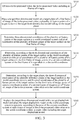
- FIG. 8 is a schematic diagram of a processing process of step S350 shown in FIG. 3 in an embodiment.
- step S350 may further include the following steps.
- Step S351 Determine a homography matrix of a target plane on a j th frame of image of the to-be-processed video relative to the target plane on the first frame of image as a homography matrix of the j th frame of image, j being a positive integer greater than or equal to 2 and less than or equal to m.
- Homography is a concept in projective geometry, and is also referred to as projective transformation.
- the homography maps a point (three-dimensional homogeneous vector) on a projective plane to another projective plane, and maps a straight line as a straight line, which has line-preserving properties.
- the homography is a linear transformation of the three-dimensional homogeneous vector, which may be represented by a 3 ⁇ 3 non-singular matrix H.
- the application scenario of placing an advertisement in a video is used as an example, a target plane B in a to-be-processed video is tracked, and an area and deformation of the target plane B in each frame of image are calculated, that is, a homography matrix of the target plane B in a current frame of image relative to the target plane B in another frame of image is calculated.
- a plane tracking method is used to track the target plane B and calculate the homography matrix.
- First, second, and third frames of images of the to-be-processed video are used as an example for description below.
- an initial value of a homography matrix H 2 of the second frame of image of the to-be-processed video is a unit matrix 1 0 0 0 1 0 0 0 1 .
- a 1 is mapped onto the second frame of image by using H 2 to obtain all pixel coordinates A 2 on the target plane B,
- a 2 ⁇ p 2 1 ( u 2 1 , v 2 1 ), p 2 2 ( u 2 2 , v 2 2 ), p 2 3 ( u 2 3 , v 2 3 ) ⁇ p 2 n ( u 2 n , v 2 n ) ⁇ .
- pixel coordinates of a first pixel in A 1 are p 1 1 ( u 1 1 , v 1 1 )
- pixel coordinates of the first pixel mapped onto A 2 are p 2 1 ( u 2 1 , v 2 1 )
- a calculation expression is as follows:
- a residual between a pixel value of each pixel of A 1 and a corresponding pixel value of each pixel of A 2 is calculated to calculate a correlation ⁇ .
- the correlation ⁇ is used for evaluating the similarity between A 1 and A 2 , which may be calculated by using a method such as the sum of squared differences (SSD) method or the Pearson correlation method.
- the homography matrix H 2 is optimized according to the correlation ⁇ (denoted as H 2,0 ). For example, an adjustment ⁇ H may be performed on H 2 , so as to maximize the value of the correlation ⁇ , and an optimization expression is as follows:
- I 1 and I 2 respectively represent the first frame of image and the second frame of image of the to-be-processed video.
- ⁇ ⁇ any one of a stochastic gradient descent method, a Gauss-Newton method, and a Newton method may be used.
- ⁇ ⁇ represents the optimal ⁇ H . Because an initial value of ⁇ H is a zero matrix, the value becomes the optimal value ⁇ ⁇ only after optimization is performed by using the Gauss-Newton method or the like.
- the optimized H 2,0 is then used as a hypothetical initial value of a homography matrix H 3 of the third frame of image of the to-be-processed video.
- a 1 is mapped onto the third frame of image by using H 3 , to obtain an optimized H 3,0 .
- the optimized H 3,0 is then used as a hypothetical initial value of a homography matrix H 4 of the fourth frame of image of the to-be-processed video ...
- the step is repeated until the m th frame of image.
- a pixel residual of a blocked part is not calculated.
- a manual selection method or some deep learning methods may be used to identify which areas are blocked. That is, all pixels involved in calculation of the correlation ⁇ in A 1 , A 2 , A 2 ⁇ A m are non-blocked pixels.
- the solutions provided in this embodiment of the present disclosure do not rely on extraction of feature points, and can still work in a case that a target plane has small brightness changes and the texture is insufficient. Moreover, information of the entire target plane can be fully used.
- an optimized homography matrix of a previous frame is used as an initial value of a homography matrix of a next frame, to optimize the homography matrix of the next frame, so that the calculation speed is faster, and the target plane in the to-be-processed video may be effectively tracked.
- the tracking is not limited by an observation angle of the target plane, and when an observation angle of the following image frame changes greatly relative to the first frame, the target plane can still be effectively tracked.
- a feature point method may alternatively be used to track the target plane. By matching feature points of different frames of images, homography matrices between the different frames of images are calculated.
- Step S352 Determine, according to the homography matrix of the j th frame of image and the pixel coordinates of the plurality of feature points of the target surface on the first frame of image, pixel coordinates of the plurality of feature points of the target surface on the j th frame of image.
- the plane tracking method is first used to calculate a homography matrix H j,0 of the target plane B on the j th frame of image relative to the target plane on the first frame of image. Then, based on the homography matrix H j,0 , pixel coordinates of the four vertices of the bottom surface of the cube on the j th frame of image denoted as: P a ,j , P b ,j , P c ,j , and P d ,j may be calculated as follows:
- the present disclosure is not limited to using the plane tracking method to calculate a homography matrix, and then calculate pixel coordinates of the four vertices of the bottom surface of the cube on a current frame of image according to the homography matrix.
- a feature point matching method may be used to directly track and match pixel coordinates of the four vertices on each frame of image.
- Step S353. Determine, according to a camera intrinsic parameter of the to-be-processed video, the three-dimensional coordinates of the plurality of feature points of the target surface in the world coordinate system, and the pixel coordinates of the plurality of feature points of the target surface on the j th frame of image, a pose of a camera coordinate system of the j th frame of image of the to-be-processed video relative to the world coordinate system.
- the deep learning model herein may be any deep learning model that can implement "single image camera calibration", for example, a perceptual measure for deep single image camera calibration.
- the homography matrix of the target plane B relative to the first frame of image is calculated.
- the pixel coordinates of the four feature points of the bottom surface of the cube on the j th frame of image are calculated as: p a, j , P b ,j , P c ,j , and p d ,j .
- the three-dimensional coordinates P a , P b , P c , and P d of the four vertices of the bottom surface of the cube, the pixel coordinates P a ,j , P b ,j , P c ,j , and P d ,j of the four vertices on the j th frame of image, and the camera intrinsic parameter K may be inputted into a perspective-n-point (PnP) algorithm to calculate a position t i and an orientation R i of the camera coordinate system of the j th frame of image relative to the world coordinate system O . Then, the cube may be projected onto the current frame of image for display.
- PnP perspective-n-point
- the present disclosure is not limited to using the PnP method to calculate the pose of the cube. Any other method may be used, provided that such a function can be implemented.
- a position t and an orientation R of a camera coordinate system of the current frame of image relative to the world coordinate system can be calculated.
- FIG. 9 is a schematic diagram of a processing process of step S360 shown in FIG. 3 in an embodiment.
- step S360 may further include the following steps.
- Step S361. Project the target three-dimensional model onto each of the second frame of image to the m th frame of image of the to-be-processed video based on the poses of the camera coordinate systems of the second frame of image to the m th frame of image of the to-be-processed video relative to the world coordinate system.
- the cube is projected onto a picture of the current frame of image based on the position and the orientation of the camera coordinate system in the current frame of image relative to the world coordinate system.
- Step S362. Replace the target three-dimensional model with the target displaylink model and place the target displaylink model on the world coordinate system of each frame of image of the to-be-processed video.
- Step S363. Project, according to the pose of the camera coordinate system of each frame of image of the to-be-processed video relative to the world coordinate system, the target displaylink model onto each frame of image of the to-be-processed video.
- Step S364. Synthesize all the frames of images of the to-be-processed video to generate the target video including the target displaylink model.
- a target three-dimensional advertisement model is used to replace the cube on each frame of image of the to-be-processed video.
- the target three-dimensional advertisement model is projected onto each frame of image, and all the frames of images are synthesized to generate the target video including the target displaylink model.
- positions and orientations of camera coordinate systems of all the frames of images of the to-be-processed video relative to the world coordinate system are calculated, the target three-dimensional advertisement model is placed on the world coordinate system, and the target three-dimensional advertisement model is projected onto each frame of image according to the pose of each frame of image for synthesis to obtain the target video including the target three-dimensional advertisement model.
- a vertex on the bottom surface of the cube is used as an origin to establish a three-dimensional rectangular coordinate system as the world coordinate system.
- a three-dimensional model of a red cola can has its own reference coordinate system.
- the reference coordinate system of the red cola can may be defined as the three-dimensional rectangular coordinate system of the cube.
- a position and an orientation of the red cola can relative to a camera coordinate system may be calculated for replacement when the position and the orientation (fixed) of the red cola can relative to the cube are obtained.
- the calculation process is as follows:
- T cam _ coca represents the pose of the red cola can relative to the camera coordinate system
- T cam _ cube represents the pose of the cube relative to the camera coordinate system
- T cube_coca represents the pose of the red cola can relative to the cube.
- the red cola can is initially placed inside the cube, and a bottom surface of the red cola can overlaps the bottom surface of the cube. Therefore, the position and the orientation of the target three-dimensional advertisement model in each frame of image relative to the camera coordinate system can be determined based on the position and the orientation of the cube relative to the camera coordinate system. Finally, the cube is removed and the red cola can is displayed.
- FIG. 10 is a flowchart of an image processing method according to still another embodiment of the present disclosure.
- the image processing method provided in this embodiment of the present disclosure may include the following steps.
- Step S1001. Obtain a video D.
- Step S1003. Drag a cube A into a first frame of image of the video D.
- Step S1004 Adjust a position and an orientation of the cube A so that four vertices of a bottom surface of the cube A fall on a target plane B of the first frame of image.
- Step S1005. Record pixel coordinates p 1 of the four vertices of the bottom surface of the cube A that fall on the target plane B on the first frame of image.
- Step S1006. Determine whether j ⁇ m. If yes, perform step S1007. If no, perform step S1013.
- Step S1007. Obtain a j th frame of image M j of the video D.
- Step S1008 Track the target plane B, and calculate a homography matrix H j,0 of the target plane B in the j th frame of image M j relative to the target plane B in the first frame of image.
- Step S1010 According to p j , calculate a position tj and an orientation R j of a camera coordinate system of the j th frame of image M j .
- Step S1011 According to the pose tj and R j , project the cube A onto the j th frame of image M j .
- Step S1013. Obtain an advertisement C.
- Step S1014 According to a recorded pose R and t of each frame of image, project the advertisement C onto each frame of image for synthesis to obtain a video D' including the advertisement C.
- relevant original data and/or processed data may be stored in a blockchain.
- original video data in which a three-dimensional advertisement has not been placed may be stored in the blockchain, and a to-be-processed video may be extracted from the original video data stored in the blockchain. Advertisements may also be stored in the blockchain.
- a target three-dimensional advertisement is extracted from the blockchain.
- the foregoing image processing method may be performed by any node in the blockchain (which may be a server and/or a user terminal device). After the image processing method is performed on the extracted to-be-processed video and three-dimensional advertisement, a target video including the three-dimensional advertisement may be obtained.
- a cube is used as a target three-dimensional model
- a target surface is a bottom surface of the cube
- a target plane is a piano plane in a to-be-processed video
- the solutions of this embodiment of the present disclosure may include: dragging the cube into a first frame of image of the to-be-processed video; tracking the piano plane in the to-be-processed video; updating a pose of the cube; and performing synthesis to obtain a target video including a three-dimensional advertisement.
- FIG. 11 is a schematic diagram of a cube and a world coordinate system of the cube according to an embodiment of the present disclosure.
- a vertex at the top left corner of the cube is used as an origin, and three sides are used as coordinate axes, to establish a world coordinate system O.
- three-dimensional coordinates P of four vertices on a bottom surface of the cube may be obtained.
- Three-dimensional coordinates of a vertex a are P a (0,0,0)
- three-dimensional coordinates of a vertex b are P b (0,0.1,0)
- three-dimensional coordinates of a vertex c are P c (0.1,0.1,0)
- three-dimensional coordinates of a vertex d are P d (0.1,0,0).
- FIG. 12 is a schematic diagram of dragging vertices of a cube to control a pose of the cube according to an embodiment of the present disclosure.
- FIG. 12 a cube is dragged into a first frame of image of a to-be-processed video, and then vertices of the cube are dragged on the first frame of image to adjust a position and an orientation of the cube.
- FIG. 12(a) shows an initial position of white dots when the cube is dragged into the first frame of image at the beginning.
- FIG. 12(b) shows that the white dots are dragged and adjusted to positions that a user expects, for example, pixel positions where the user expects the four vertices of the bottom surface and one vertex of a top surface of the cube to appear.
- FIG. 12(c) shows that a pose of the cube is automatically adjusted according to the positions of the white dots adjusted in FIG.
- the user may adjust the position and the orientation of the cube by dragging the white dots.
- FIG. 12 shows five white dots to adjust five vertices of the cube, an actual operation is not limited thereto. For example, four, six, or seven vertices may be used, or even eight or more white dots may alternatively be used to respectively adjust eight vertices of the cube.
- different sides of the cube may further be set to be drawn in different colors, so as to distinguish different surfaces.
- four sides of the bottom surface are represented in blue
- four sides of the top surface are represented in red
- four sides of a side surface are represented in green, but the present disclosure is not limited thereto.
- FIG. 13 is a schematic diagram of rotating a cube to control a pose of the cube according to an embodiment of the present disclosure.
- FIG. 13(a) shows an initial position of the cube dragged into a first frame of image.
- FIG. 13(b) shows that a user rotates the cube to achieve a final effect of FIG. 13(c) .
- four vertices of a bottom surface of the cube fall on a target plane, and the pose of the cube appears to be correct.
- the user may drag the cube by pressing an arrow displayed on the first frame of image with a finger or a mouse, or may rotate the cube by pressing an arc displayed on the first frame of image, to adjust the pose of the cube.
- the pose of the cube may be adjusted in a manner of manual interaction, or the position and the orientation of the cube may be automatically adjusted after the target plane in the first frame of image is recognized through a method based on AI, and then the cube is placed on the target plane B.
- a purpose of the adjustment is to adjust the position and the orientation of the cube, so that the four vertices a, b, c, d of the bottom surface of the cube fall on the target plane B.
- the pixel coordinates of the four vertices on the first frame of image in this case are recorded.
- the three-dimensional coordinates of the four vertices of the bottom surface of the cube, the pixel coordinates of the four vertices on the first frame of image, and the camera intrinsic parameter are inputted into the PnP algorithm to calculate the position and the orientation of the camera coordinate system of the first frame of image relative to the world coordinate system O .
- FIG. 14 is a schematic diagram of tracking a target plane where a cube is located according to an embodiment of the present disclosure.
- FIG. 14(a) is assumed to be the target plane displayed on a first frame of image of a to-be-processed video.
- FIG. 14(b) is assumed to be the target plane displayed on a second frame of image.
- FIG. 14(c) is assumed to be the target plane displayed on a third frame of image.
- the target plane is represented by a quadrilateral including two triangles.
- FIG. 15 is a schematic diagram of displaying a cube on each frame of image according to an embodiment of the present disclosure.
- FIG. 15(a) is assumed to be the cube displayed on the first frame of image of the to-be-processed video.
- FIG. 15(b) is assumed to be the cube displayed on the second frame of image.
- FIG. 15(c) is assumed to be the cube displayed on the third frame of image.
- FIG. 16 is a schematic diagram of placing a three-dimensional advertisement on each frame of image according to an embodiment of the present disclosure.
- FIG. 16(a) is assumed to be a red cola can displayed on the first frame of image of the to-be-processed video.
- FIG. 16(b) is assumed to be the red cola can displayed on the second frame of image.
- FIG. 16(c) is assumed to be the red cola can displayed on the third frame of image.
- the image processing is performed on the video in, for example, an image processing interface or page.
- FIG. 17 is a block diagram of an image processing apparatus according to an embodiment of the present disclosure.
- an image processing apparatus 1700 may include: a to-be-processed video obtaining module 1710, a three-dimensional model placing module 1720, a first coordinate determining module 1730, a first pose determining module 1740, a second pose determining module 1750, and a target video generating module 1760.
- the to-be-processed video obtaining module 1710 may be configured to obtain a to-be-processed video, the to-be-processed video including m frames of images, m being a positive integer greater than or equal to 2.
- the three-dimensional model placing module 1720 may be configured to place a target three-dimensional model on a target plane of a first frame of image of the to-be-processed video, a plurality of feature points of a target surface of the target three-dimensional model falling on the target plane.
- the first coordinate determining module 1730 may be configured to determine three-dimensional coordinates of the plurality of feature points of the target surface in a world coordinate system and pixel coordinates of the plurality of feature points of the target surface on the first frame of image
- the first pose determining module 1740 may be configured to determine, according to the three-dimensional coordinates of the plurality of feature points of the target surface in the world coordinate system and the pixel coordinates of the plurality of feature points of the target surface on the first frame of image, a pose of a camera coordinate system of the first frame of image relative to the world coordinate system.
- the second pose determining module 1750 may be configured to determine and obtain, according to the target plane, the three-dimensional coordinates of the plurality of feature points of the target surface in the world coordinate system, and the pixel coordinates of the plurality of feature points of the target surface on the first frame of image, poses of camera coordinate systems of a second frame of image to an m th frame of image of the to-be-processed video relative to the world coordinate system.
- the target video generating module 1760 is configured to replace the target three-dimensional model with a target displaylink model and place the target displaylink model on the world coordinate system to generate, according to the pose of the camera coordinate system of each frame of image of the to-be-processed video relative to the world coordinate system, a target video including the target displaylink model.
- the second pose determining module 1750 may include: a homography matrix determining unit, which may be configured to determine a homography matrix of a target plane on a j th frame of image of the to-be-processed video relative to the target plane on the first frame of image as a homography matrix of the j th frame of image, j being a positive integer greater than or equal to 2 and less than or equal to m; a pixel coordinate determining unit, which may be configured to obtain, according to the homography matrix of the j th frame of image and the pixel coordinates of the plurality of feature points of the target surface on the first frame of image, pixel coordinates of the plurality of feature points of the target surface on the j th frame of image; and a pose determining unit, which may be configured to determine, according to a camera intrinsic parameter of the to-be-processed video, the three-dimensional coordinates of the plurality of feature points of the target surface in the world coordinate system, and the pixel coordinates of the
- the target video generating module 1760 may include: a three-dimensional mapping unit, which may be configured to project the target three-dimensional model onto each of the second frame of image to the m th frame of image of the to-be-processed video based on the poses of the camera coordinate systems of the second frame of image to the m th frame of image of the to-be-processed video relative to the world coordinate system; a display model replacing unit, which may be configured to replace the target three-dimensional model with the target displaylink model and place the target displaylink model on the world coordinate system of each frame of image of the to-be-processed video; a display model projecting unit, which may be configured to project, according to the pose of the camera coordinate system of each frame of image of the to-be-processed video relative to the world coordinate system, the target displaylink model onto each frame of image of the to-be-processed video; and an image synthesizing unit, which may be configured to synthesize all the frames of images of the to-be-process
- the three-dimensional model placing module 1720 may include: a three-dimensional model drag-in unit, which may be configured to add the target three-dimensional model to the first frame of image in response to an adding instruction of adding the target three-dimensional model to the first frame of image; a target surface determining unit, which may be configured to determine the target surface of the target three-dimensional model and the plurality of feature points of the target surface; and a three-dimensional model pose adjusting unit, which may be configured to adjust a pose of the target three-dimensional model so that the plurality of feature points of the target surface fall on the target plane.
- the three-dimensional model pose adjusting unit may include: a feature point adjusting subunit or a three-dimensional model rotating subunit.
- the feature point adjusting subunit may be configured to adjust the plurality of feature points of the target three-dimensional model so that the plurality of feature points of the target surface fall on the target plane.
- the three-dimensional rotating subunit may be configured to rotate the target three-dimensional model so that the plurality of feature points of the target surface fall on the target plane.
- the first coordinate determining module 1730 may include: a world coordinate system establishing unit, which may be configured to establish the world coordinate system according to the target three-dimensional model; a three-dimensional coordinate determining unit, which may be configured to determine the three-dimensional coordinates of the plurality of feature points of the target surface in the world coordinate system; and a pixel coordinate recording unit, which may be configured to record the pixel coordinates of the plurality of feature points of the target surface on the first frame of image in a case that the plurality of feature points of the target surface fall on the target plane.
- a world coordinate system establishing unit which may be configured to establish the world coordinate system according to the target three-dimensional model
- a three-dimensional coordinate determining unit which may be configured to determine the three-dimensional coordinates of the plurality of feature points of the target surface in the world coordinate system
- a pixel coordinate recording unit which may be configured to record the pixel coordinates of the plurality of feature points of the target surface on the first frame of image in a case that the plurality of feature points of the target
- the target three-dimensional model may be a cube having a predetermined side length.
- the world coordinate system establishing unit may include: an origin determining subunit, which may be configured to use a feature point at the top left corner of the cube as an origin; and a coordinate axis determining subunit, which may be configured to use three sides of the cube that intersect the feature point at the top left corner as coordinate axes to establish the world coordinate system.
- the image processing apparatus 1700 may further include: a plane determining module, which may be configured to process the first frame of image by using a neural network model to obtain at least one plane on the first frame of image; and a target plane determining module, which may be configured to determine the target plane from the at least one plane in response to a plane selection instruction on the first frame of image.
- a plane determining module which may be configured to process the first frame of image by using a neural network model to obtain at least one plane on the first frame of image
- a target plane determining module which may be configured to determine the target plane from the at least one plane in response to a plane selection instruction on the first frame of image.
- modules, units, or subunits of a device for action execution are mentioned in the foregoing detailed descriptions, the division is not mandatory.
- the features and functions of two or more modules, units, or subunits described above may be embodied in one module, unit, or subunit.
- a module, a unit, or a subunit described above may further be divided into a plurality of modules, units, or subunits to implement functions and features.
- the software product may be stored in a non-volatile storage medium (which may be a CD-ROM, a USB flash drive, a removable hard disk, or the like) or on the network including several instructions for instructing a computer device (which may be a personal computer, a server, a mobile terminal, a network device, or the like) to execute the methods described in the implementations of the present disclosure.
- a non-volatile storage medium which may be a CD-ROM, a USB flash drive, a removable hard disk, or the like
- a computer device which may be a personal computer, a server, a mobile terminal, a network device, or the like
Abstract
Description
- This application claims priority to
Chinese Patent Application No. 201910854877.X - The present disclosure relates to the field of computer and communication technologies, and specifically, to an image processing method and apparatus, an electronic device, and a computer-readable storage medium.
- Video-in advertisement is a technology of intelligently placing an advertisement in a produced video by using a computer vision (CV) technology. Compared with conventional video technologies such as adding an advertisement to the beginning/end of a video or displaying an advertisement on a floating layer on a video for sale, the video-in advertisement has advantages such as better experience and higher traffic coverage and becomes technological means competitively developed at home and abroad.
- The information disclosed in the above background part is only used for enhancing the understanding of the background of the present disclosure, and therefore may include information that does not constitute the related art known to a person of ordinary skill in the art.
- Embodiments of the present disclosure provide an image processing method and apparatus, an electronic device, and a computer-readable storage medium, which can improve the efficiency and effect of placing a displaylink model in a video.
- Other features and advantages of the present disclosure will be apparent through the following detailed description, or partly learned through practice of the present disclosure.
- According to an aspect of the present disclosure, an image processing method is provided, including: obtaining a to-be-processed video, the to-be-processed video including m frames of images, m being a positive integer greater than or equal to 2; placing a target three-dimensional model on a target plane of a first frame of image of the to-be-processed video, a plurality of feature points of a target surface of the target three-dimensional model falling on the target plane; determining three-dimensional coordinates of the plurality of feature points of the target surface in a world coordinate system and pixel coordinates of the plurality of feature points of the target surface on the first frame of image; determining, according to the three-dimensional coordinates of the plurality of feature points of the target surface in the world coordinate system and the pixel coordinates of the plurality of feature points of the target surface on the first frame of image, a pose of a camera coordinate system of the first frame of image relative to the world coordinate system; determining, according to the target plane, the three-dimensional coordinates of the plurality of feature points of the target surface in the world coordinate system, and the pixel coordinates of the plurality of feature points of the target surface on the first frame of image, poses of camera coordinate systems of a second frame of image to an mth frame of image of the to-be-processed video relative to the world coordinate system; and replacing the target three-dimensional model with a target displaylink model and placing the target displaylink model on the world coordinate system to generate, according to the pose of the camera coordinate system of each frame of image of the to-be-processed video relative to the world coordinate system, a target video including the target displaylink model.
- According to an aspect of the present disclosure, an image processing apparatus is provided, including: a to-be-processed video obtaining module, configured to obtain a to-be-processed video, the to-be-processed video including m frames of images, m being a positive integer greater than or equal to 2; a three-dimensional model placing module, configured to place a target three-dimensional model on a target plane of a first frame of image of the to-be-processed video, a plurality of feature points of a target surface of the target three-dimensional model falling on the target plane; a first coordinate determining module, configured to determine three-dimensional coordinates of the plurality of feature points of the target surface in a world coordinate system and pixel coordinates of the plurality of feature points of the target surface on the first frame of image; a first pose determining module, configured to determine, according to the three-dimensional coordinates of the plurality of feature points of the target surface in the world coordinate system and the pixel coordinates of the plurality of feature points of the target surface on the first frame of image, a pose of a camera coordinate system of the first frame of image relative to the world coordinate system; a second pose determining module, configured to determine, according to the target plane, the three-dimensional coordinates of the plurality of feature points of the target surface in the world coordinate system, and the pixel coordinates of the plurality of feature points of the target surface on the first frame of image, poses of camera coordinate systems of a second frame of image to an mth frame of image of the to-be-processed video relative to the world coordinate system; and a target video generating module, configured to replace the target three-dimensional model with a target displaylink model and place the target displaylink model on the world coordinate system to generate, according to the pose of the camera coordinate system of each frame of image of the to-be-processed video relative to the world coordinate system, a target video including the target displaylink model.
- According to an aspect of the embodiments of the present disclosure, a computer-readable storage medium is provided, storing a computer program, the program, when executed by a processor, implementing the image processing method according to the foregoing embodiments.
- According to an aspect of the embodiments of the present disclosure, an electronic device is provided, including: one or more processors; and a storage apparatus, configured to store one or more programs, the one or more programs, when executed by the one or more processors, causing the one or more processors to implement the image processing method according to the foregoing embodiments.
- In technical solutions provided in some embodiments of the present disclosure, on one hand, a target three-dimensional model is placed in a first frame of image of a to-be-processed video. The target three-dimensional model is placed on a target plane in the first frame of image, and a pose of the target three-dimensional model in the first frame of image relative to a camera coordinate system is calculated. By tracking the target plane, a pose of the target three-dimensional model in each following frame of image of the to-be-processed video relative to a camera coordinate system may be calculated, and then, by replacing the target three-dimensional model in the to-be-processed video with a target displaylink model, the target displaylink model may be automatically placed on each frame of image of the to-be-processed video. On the other hand, the target plane is tracked. Such a manner does not rely on the calculation on feature points of images in the to-be-processed video nor requires a video with a large parallax, which results in a small calculation amount, a fast speed, convenient operation, and high accuracy, and may be applied to more videos, thereby improving the efficiency and effect of placing the target displaylink model in the video.
- It is to be understood that the above general descriptions and the following detailed descriptions are merely for exemplary and explanatory purposes, and cannot limit the present disclosure.
- The accompanying drawings herein, which are incorporated in the specification as a part of the specification, show embodiments in accordance with the present disclosure, and together with the specification are used to explain the principle of the present disclosure. Apparently, the accompanying drawings in the following description show merely some embodiments of the present disclosure, and a person of ordinary skill in the art may still derive other drawings from these accompanying drawings without creative efforts. In the accompanying drawings:
-
FIG. 1 is a schematic diagram of an exemplary system architecture to which an image processing method or an image processing apparatus according to embodiments of the present disclosure may be applied. -
FIG. 2 is a schematic structural diagram of a computer system suitable for implementing an electronic device according to an embodiment of the present disclosure. -
FIG. 3 is a flowchart of an image processing method according to an embodiment of the present disclosure. -
FIG. 4 is a flowchart of an image processing method according to another embodiment of the present disclosure. -
FIG. 5 is a schematic diagram of a processing process of step S320 shown inFIG. 3 in an embodiment. -
FIG. 6 is a schematic diagram of a processing process of step S330 shown inFIG. 3 in an embodiment. -
FIG. 7 is a schematic diagram of a processing process of step S331 shown inFIG. 6 in an embodiment. -
FIG. 8 is a schematic diagram of a processing process of step S350 shown inFIG. 3 in an embodiment. -
FIG. 9 is a schematic diagram of a processing process of step S360 shown inFIG. 3 in an embodiment. -
FIG. 10 is a flowchart of an image processing method according to still another embodiment of the present disclosure. -
FIG. 11 is a schematic diagram of a cube and a world coordinate system of the cube according to an embodiment of the present disclosure. -
FIG. 12 is a schematic diagram of dragging vertices of a cube to control a pose of the cube according to an embodiment of the present disclosure. -
FIG. 13 is a schematic diagram of rotating a cube to control a pose of the cube according to an embodiment of the present disclosure. -
FIG. 14 is a schematic diagram of tracking a target plane where a cube is located according to an embodiment of the present disclosure. -
FIG. 15 is a schematic diagram of displaying a cube on each frame of image according to an embodiment of the present disclosure. -
FIG. 16 is a schematic diagram of placing a three-dimensional advertisement on each frame of image according to an embodiment of the present disclosure. -
FIG. 17 is a block diagram of an image processing apparatus according to an embodiment of the present disclosure. - Now, exemplary implementations are described comprehensively with reference to the accompanying drawings. However, the exemplary implementations may be implemented in a plurality of forms, and are not limited to the examples described herein. On the contrary, such implementations are provided to make the present disclosure more comprehensive and complete, and fully convey the concepts of the exemplary implementations to a person skilled in the art.
- In addition, the described features, structures, or characteristics may be combined in one or more embodiments in any appropriate manner. In the following descriptions, a lot of specific details are provided to give a comprehensive understanding of the embodiments of the present disclosure. However, a person of skill in the art is to be aware that, the technical solutions in the present disclosure may be implemented without one or more of the particular details, or another method, element, material, apparatus, step, and the like may be used. In other cases, well-known methods, apparatuses, implementations, or operations are not shown or described in detail, in order not to obscure the aspects of the present disclosure.
- The block diagrams shown in the accompanying drawings is merely a functional entity and does not necessarily correspond to a physically independent entity. To be specific, such functional entities may be implemented in the form of software, or implemented in one or more hardware modules or integrated circuits, or implemented in different networks and/or processor apparatuses and/or microcontroller apparatuses.
- The flowcharts shown in the accompanying drawings are merely exemplary descriptions and do not necessarily include all of the content and operations/steps, nor are the flowcharts necessarily performed in the order described. For example, some operations/steps may be further divided, and some operations/steps may be combined or partially combined. Therefore, an actual execution order may be changed according to the actual situation.
- Artificial intelligence (AI) is a theory, method, technology, and application system that uses a digital computer or a machine controlled by the digital computer to simulate, extend, and expand human intelligence, perceive an environment, obtain knowledge, and use knowledge to obtain an optimal result. In other words, AI is a comprehensive technology in computer science and attempts to understand the essence of intelligence and produce a new intelligent machine that can react in a manner similar to human intelligence. AI is to study the design principles and implementation methods of various intelligent machines, to enable the machines to have the functions of perception, reasoning, and decision-making.
- The AI technology is a comprehensive discipline, and relates to a wide range of fields including hardware-level technology and software-level technology. The basic AI technology generally includes technologies such as sensor, dedicated AI chip, cloud computing, distributed storage, big data processing technology, operating/interaction system, and electromechanical integration. The AI software technology mainly includes several major directions such as Computer Vision (CV) technology, speech processing technology, natural language processing technology, and machine learning/deep learning.
- The CV technology is a science that studies how to use a machine to "see", and furthermore, is machine vision that a camera and a computer are used for replacing human eyes to perform recognition, tracking, measurement, and the like on a target, and further perform graphic processing, so that the computer processes the target into an image more suitable for human eyes to observe, or an image transmitted to an instrument for detection. As a scientific subject, CV studies related theories and technologies attempts to establish an AI system that can obtain information from images or multidimensional data. The CV technology generally includes technologies such as image processing, image recognition, image semantic understanding, image retrieval, optical character recognition (OCR), video processing, video semantic understanding, video content/behavior recognition, three-dimensional object reconstruction, a 3D technology, virtual reality (VR), augmented reality (AR), synchronous positioning, and map construction, and further include biological feature recognition technologies such as common face recognition and fingerprint recognition.
- Machine learning (ML) is a multi-field interdisciplinary subject involving the probability theory, statistics, the approximation theory, convex analysis, the algorithm complexity theory, and the like, which specializes in the study of how a computer simulates or implements learning behavior of humans to obtain new knowledge or skills, and reorganize an obtained knowledge structure to keep improving its performance. ML is a core of AI and a fundamental way to make the computer intelligent, and is applicable to various fields of AI. ML and deep learning generally include technologies such as artificial neural network, belief network, reinforcement learning, transfer learning, inductive learning, and teaching learning.
- A blockchain is a new application mode of computer technologies such as distributed data storage, point-to-point transmission, consensus mechanism, and encryption algorithm. The blockchain is essentially a decentralized database and a series of associated data blocks generated in a cryptographic manner. Each data block includes information about a batch of network transactions for verifying the validity of the information (for anti-counterfeiting) and generating a next block. The blockchain may include an underlying blockchain platform, a platform product service layer, and application service layer.
- The underlying blockchain platform may include user management, basic service, smart contract, operation monitoring, and other processing modules. The user management module is responsible for identity information management of all blockchain participants, including maintenance of public and private key generation (account management), key management, and maintenance of a correspondence between a real identity of a user and a blockchain address (authority management), and when authorized, supervising and auditing transactions of some real identities and providing rule configuration for risk control (risk control audit). The basic service module is deployed on all blockchain node devices to verify the validity of service requests, and record valid requests in a storage after consensus. For a new service request, the basic service module first performs interface adaption analysis and authentication processing (interface adaption), and then encrypts service information by using a consensus algorithm (consensus management), and after the encryption, the information is completely and consistently transmitted to a shared ledger (network communication), and is recorded and stored. The smart contract module is responsible for contract registration and issuance, contract triggering, and contract execution. Developers may define contract logic through a specific programming language and publish the logic on the blockchain (contract registration). According to the logic of contract terms, the smart contract module completes the contract logic by invoking a key or when triggered by another event, which also provides functions of contract upgrade and cancellation. The operation monitoring module is mainly responsible for deployment during the product release process, configuration modification, contract settings, cloud adaptation, and visual outputting of a real-time status during product operation, for example, warning, monitoring network conditions, and monitoring a health status of a node device.
- The platform product service layer provides basic capabilities and implementation frameworks for typical applications. Based on the basic capabilities, the developers may superimpose service characteristics to complete a blockchain implementation of the service logic. The application service layer provides application services based on a blockchain solution for service participants to use.
- The solutions provided in the embodiments of this disclosure relate to CV and ML of AI, blockchain, and other technologies, which are specifically described by using the following embodiments.
-
FIG. 1 is a schematic diagram of anexemplary system architecture 100 to which an image processing method or an image processing apparatus according to embodiments of the present disclosure may be applied. - As shown in
FIG. 1 , thesystem architecture 100 may include one or more ofterminal devices network 104, and aserver 105. Thenetwork 104 is configured to provide a medium of a communication link between theserver 105 and theterminal devices network 104 may include various connection types, such as a wired or wireless communication link, or a fiber optic cable. - It is to be understood that the quantities of terminal devices, networks, and servers in
FIG. 1 are only schematic. There may be any quantities of terminal devices, networks and servers according to an actual requirement. For example, theserver 105 may be a server cluster that includes a plurality of servers. - Users may use the
terminal devices server 105 via thenetwork 104 to receive or send messages or the like. Theterminal devices - The
server 105 may be a server that provides various services. For example, a user uses the terminal device 103 (which may alternatively be theterminal device 101 or 102) to open a to-be-processed video, drag a target three-dimensional model onto a first frame of image of the to-be-processed video, and adjust a pose of the target three-dimensional model so that a plurality of feature points of a target surface of the target three-dimensional model fall on a target plane of the first frame of image. The to-be-processed video includes m frames of images, m being a positive integer greater than or equal to 2. The user uses theterminal device 103 to send a request to theserver 105. The server 105 may obtain, based on relevant information carried in the request, three-dimensional coordinates of the plurality of feature points of the target surface in a world coordinate system and pixel coordinates of the plurality of feature points of the target surface on the first frame of image; determine, according to the three-dimensional coordinates of the plurality of feature points of the target surface in the world coordinate system and the pixel coordinates of the plurality of feature points of the target surface on the first frame of image, a pose of a camera coordinate system of the first frame of image relative to the world coordinate system; determine, according to the target plane, the three-dimensional coordinates of the plurality of feature points of the target surface in the world coordinate system, and the pixel coordinates of the plurality of feature points of the target surface on the first frame of image, poses of camera coordinate systems of a second frame of image to an mth frame of image of the to-be-processed video relative to the world coordinate system; and replace the target three-dimensional model with a target displaylink model and place the target displaylink model on the world coordinate system to generate, according to the pose of the camera coordinate system of each frame of image of the to-be-processed video relative to the world coordinate system, a target video including the target displaylink model. Theserver 105 may return the target video to theterminal device 103, so that the user may watch the displayed target video that includes the target displaylink model on theterminal device 103. - In another example, the terminal device 103 (which may alternatively be the
terminal device 101 or 102) may be a smart television, a VR/AR helmet display, or a mobile terminal on which an instant messaging or video application (APP) are installed, for example, a smartphone or a tablet computer. The user may send various requests to theserver 105 through the smart television, the VR/AR helmet display, or the instant messaging or video APP. Theserver 105 may obtain, based on the request, feedback information in response to the request and return the feedback information to the smart television, the VR/AR helmet display, or the instant messaging or video APP, to display the returned feedback information through the smart television, the VR/AR helmet display, or the instant messaging or video APP. -
FIG. 2 is a schematic structural diagram of a computer system suitable for implementing an electronic device according to an embodiment of the present disclosure. - A
computer system 200 for an electronic device shown inFIG. 2 is merely an example, and does not constitute any limitation on functions and scopes of use of the embodiments of the present disclosure. - As shown in
FIG. 2 , thecomputer system 200 includes a central processing unit (CPU) 201, which may perform various proper actions and processing based on a program stored in a read-only memory (ROM) 202 or a program loaded from astorage part 208 into a random access memory (RAM) 203. TheRAM 203 further stores various programs and data necessary for system operations. TheCPU 201, theROM 202, and theRAM 203 are connected to each other by using abus 204. An input/output (I/O)interface 205 is also connected to thebus 204. - The following components are connected to the I/O interface 205: an
input part 206 including a keyboard, a mouse, or the like, anoutput part 207 including a cathode ray tube (CRT), a liquid crystal display (LCD), a speaker, or the like, thestorage part 208 including a hard disk or the like, and acommunication part 209 including a network interface card such as a local area network (LAN) card or a modem. Thecommunication part 209 performs communication processing via a network such as the Internet. Adriver 210 is also connected to the I/O interface 205 as required. Aremovable medium 211, such as a magnetic disk, an optical disc, a magneto-optical disk, or a semiconductor memory, is installed on thedriver 210 as required, so that a computer program read therefrom is installed into thestorage part 208 as required. - Particularly, according to the embodiments of the present disclosure, the processes described in the following with reference to the flowcharts may be implemented as computer software programs. For example, the embodiments of the present disclosure include a computer program product, including a computer program carried on a computer-readable storage medium. The computer program includes program code for performing the methods shown in the flowcharts. In such an embodiment, the computer program may be downloaded from a network via the
communication part 209 and installed, and/or installed from theremovable medium 211. When the computer program is executed by theCPU 201, various functions defined in the method and/or apparatus of this disclosure are executed. - The computer-readable storage medium shown in the present disclosure may be a computer-readable signal medium, a computer-readable storage medium, or any combination thereof. The computer-readable storage medium may include, but is not limited to, for example, an electrical, magnetic, optical, electromagnetic, infrared, or semiconductor system, apparatus, or device, or any combination thereof. A more specific example of the computer-readable storage medium may include, but is not limited to: an electrical connection with one or more wires, a portable computer disk, a hard disk, a RAM, a ROM, an erasable programmable read-only memory (EPROM or a flash memory), an optical fiber, a portable compact disc read-only memory (CD-ROM), an optical storage device, a magnetic storage device, or any suitable combination thereof. In the present disclosure, the computer-readable storage medium may be any tangible medium including or storing a program, and the program may be used by or in combination with an instruction execution system, apparatus, or device. In the present disclosure, the computer-readable signal medium may be a data signal included in a baseband or propagated as a part of a carrier, in which computer-readable program code is carried. The propagated data signal may be in a plurality of forms, including but not limited to, an electromagnetic signal, an optical signal, or any suitable combination thereof. The computer-readable signal medium may alternatively be any computer-readable storage medium other than the computer-readable storage medium. The computer-readable storage medium may send, propagate, or transmit a program for use by or in combination with an instruction execution system, apparatus, or device. The program code included in the computer-readable storage medium may be transmitted by using any appropriate medium, including but not limited to: a wireless medium, a wire, an optical cable, radio frequency (RF), or the like, or any suitable combination thereof.
- The flowcharts and block diagrams in the accompanying drawings show architectures, functions, and operations that may be implemented for the method, the apparatus, and the computer program product according to the embodiments of the present disclosure. In this regard, each box in the flowchart or the block diagram may represent a module, a program segment, or a part of code. The module, the program segment, or the part of code includes one or more executable instructions used for implementing specified logic functions. In some implementations used as substitutes, functions marked in boxes may alternatively occur in a sequence different from that marked in an accompanying drawing. For example, two boxes shown in succession may actually be performed basically in parallel, and sometimes the two boxes may be performed in a reverse sequence. This is determined by a related function. Each box in a block diagram or a flowchart and a combination of boxes in the block diagram or the flowchart may be implemented by using a dedicated hardware-based system configured to perform a designated function or operation, or may be implemented by using a combination of dedicated hardware and a computer instruction.
- Related modules and/or units and/or subunits described in the embodiments of the present disclosure may be implemented in a software manner, or may be implemented in a hardware manner, and the described modules and/or units and/or subunits may alternatively be set in a processor. Names of the modules and/or units and/or subunits do not constitute a limitation on the modules and/or units and/or subunits in a specific case.
- According to another aspect, this disclosure further provides a computer-readable storage medium. The computer-readable storage medium may be included in the electronic device described in the foregoing embodiments, or may exist alone and is not disposed in the electronic device. The computer-readable storage medium carries one or more programs, the one or more programs, when executed by the electronic device, causing the electronic device to implement the method described in the following embodiments. For example, the electronic device may implement steps shown in
FIG. 3 ,FIG. 4 ,FIG. 5 ,FIG. 6 ,FIG. 7 ,FIG. 8 ,FIG. 9 , orFIG. 10 . - In the related art, a method of placing a three-dimensional advertisement into a video is generally performing three-dimensional reconstruction on an entire scene in each frame of image of a video based on a three-dimensional reconstruction algorithm such as simultaneous localization and mapping (SLAM) or structure from motion (SFM), to obtain a three-dimensional space, and calculating a position and an orientation of a camera of each frame of image. Then a three-dimensional advertisement model is added to the three-dimensional space and projected onto each frame of image, to implement placement of a three-dimensional advertisement.
-
FIG. 3 is a flowchart of an image processing method according to an embodiment of the present disclosure. The method provided in this embodiment of the present disclosure may be executed by any electronic device having computing and processing capabilities, for example, one or more of theterminal devices server 105 shown inFIG. 1 . - As shown in
FIG. 3 , the image processing method provided in this embodiment of the present disclosure may include the following steps. - Step S310. Obtain a to-be-processed video, the to-be-processed video including m frames of images, m being a positive integer greater than or equal to 2.
- In this embodiment of the present disclosure, the to-be-processed video may be, for example, a video in which an advertisement is currently to be placed. The to-be-processed video may be deframed to extract the m frames of images that are included in the video and in which the advertisement is to be placed, but herein, the to-be-processed video is not limited to including only the m frames of images.
- Step S320. Place a target three-dimensional model on a target plane of a first frame of image of the to-be-processed video, a plurality of feature points of a target surface of the target three-dimensional model falling on the target plane.
- In this embodiment of the present disclosure, the first frame of image may refer to a start frame of image among the extracted m frames of images sorted by time, and may be numbered 0 or 1 (using the number being 1 as an example below). However, the present disclosure is not limited thereto. In other embodiments, any one of the extracted m frames of images may alternatively be used as the first frame of image.
- In this embodiment of the present disclosure, the target plane of the first frame of image refers to a plane on which a user expects to place the advertisement, for example, any one of a desktop, a stool surface, a piano surface, a book table top, or a floor in the first frame of image.
- In this embodiment of the present disclosure, the target three-dimensional model may be any one of a cube, a cuboid, a Rubik's cube, a quadrangular pyramid, a sphere, or a cylinder, or the like, which is not limited in the present disclosure. Alternatively, a three-dimensional model of an advertisement to be placed, for example, a red cola can mentioned in the following embodiments, may be directly put in the first frame of image as the target three-dimensional model. In the following example descriptions, an example in which the target three-dimensional model is a cube is used for description. For example, if the advertisement to be placed is a red cola can, a cube with a side length of 0.1 meter may be used as the target three-dimensional model. However. the present disclosure is not limited thereto, provided that the size of the placed target three-dimensional model is approximately adapted to the size of the advertisement to be placed. When the shape and size of the advertisement that the user expects to place change, the shape and size of the placed target three-dimensional model may be adjusted adaptively. The cube is used as the target three-dimensional model because the shape of the cube can intuitively show whether a pose is correct, making it more convenient to adjust a position and an orientation.
- Using a cube as an example, it may be determined that a target surface of the cube is a bottom surface (a plane formed by an x axis and a y axis in a world coordinate system) of the cube, and four vertices of the bottom surface of the cube may be used as four feature points. A position and an orientation (a pose for short) of the cube on the first frame of image are adjusted, so that the four vertices of the bottom surface of the cube fall on the target plane.
- In other embodiments, it is not limited to using the bottom surface of the cube as a target surface. Any surface of the cube may be used as a target surface. In addition, it is not limited to using the vertices of the target surface as feature points. Any feature points on the target surface that facilitate calibration may be used. Moreover, a quantity of the feature points is not limited to four in the foregoing example. For example, five feature points or six feature points may alternatively be used. If another three-dimensional model is used as the target three-dimensional model, the target surface is not limited to a shape having vertices, and may be in a shape without vertices such as a circle/ellipse. For example, if a cylinder is used as the target three-dimensional model, a circle at a bottom surface of the cylinder is used as a target surface, and several feature points on the circle can be used for calibration. Even though the determined target surface is a pattern having vertices, the target surface is not limited to patterns such as a quadrilateral. For example, if the pattern is a triangle, the triangle has only three vertices, and the three vertices and another feature point may be used as a plurality of feature points of the target surface, provided that three-dimensional coordinates of at least four feature points taken in the world coordinate system of the target three-dimensional model can be determined. In another example, if the target three-dimensional model is a sphere, the center of the sphere may be used as an origin of coordinates. A cross-section intersecting the center is a target surface, and points on a circle where the cross-section and the sphere intersect are feature points.
- Step S330. Determine three-dimensional coordinates of the plurality of feature points of the target surface in a world coordinate system and pixel coordinates of the plurality of feature points of the target surface on the first frame of image.
- Step S340. Determine, according to the three-dimensional coordinates of the plurality of feature points of the target surface in the world coordinate system and the pixel coordinates of the plurality of feature points of the target surface on the first frame of image, a pose of a camera coordinate system of the first frame of image relative to the world coordinate system.
- Step S350. Determine, according to the target plane, the three-dimensional coordinates of the plurality of feature points of the target surface in the world coordinate system, and the pixel coordinates of the plurality of feature points of the target surface on the first frame of image, poses of camera coordinate systems of a second frame of image to an mth frame of image of the to-be-processed video relative to the world coordinate system.
- Step S360. Replace the target three-dimensional model with a target displaylink model and place the target displaylink model on the world coordinate system to generate, according to the pose of the camera coordinate system of each frame of image of the to-be-processed video relative to the world coordinate system, a target video including the target displaylink model.
- In the present disclosure, shapes and structures of the selected target three-dimensional model and target displaylink model are not limited, and the target plane and the target surface are not limited to triangles or quadrilaterals, and may be any shape such as a circle or an ellipse.
- In this embodiment of the present disclosure, the application scenario of placing an advertisement in a video is still used as an example, and the target displaylink model may be, for example, a target three-dimensional advertisement model. A person skilled in the art can understand that solutions provided in this embodiment of the present disclosure may also be used for placing a two-dimensional advertisement, because the two-dimensional advertisement may be considered as an infinitely thin three-dimensional advertisement.
- According to the image processing method provided in this embodiment of the present disclosure, on one hand, a target three-dimensional model is placed in a first frame of image of a to-be-processed video. The target three-dimensional model is placed on a target plane in the first frame of image, and a pose of the target three-dimensional model in the first frame of image relative to a camera coordinate system is calculated. By tracking the target plane, a pose of the target three-dimensional model in each following frame of image of the to-be-processed video relative to a camera coordinate system may be calculated, and then, by replacing the target three-dimensional model in the to-be-processed video with a target displaylink model, the target displaylink model may be automatically placed on each frame of image of the to-be-processed video. On the other hand, the target plane is tracked. Such a manner does not rely on the calculation on feature points of images in the to-be-processed video nor does it requires a video with a large parallax, which results in a small calculation amount, a fast speed, convenient operation, and high accuracy, and may be applied to more videos, thereby improving the efficiency and effect of placing the target displaylink model in the video.
-
FIG. 4 is a flowchart of an image processing method according to another embodiment of the present disclosure. - As shown in
FIG. 4 , a difference from the foregoing embodiment is that the image processing method provided in this embodiment of the present disclosure may further include the following steps. - Step S410. Process the first frame of image by using a neural network model to obtain at least one plane on the first frame of image.
- In this embodiment of the present disclosure, the neural network model may be any deep learning model capable of performing instance segmentation, for example, mask region-convolutional neural network (Mask R-CNN).
- In an exemplary embodiment, the method may further include: obtaining a training data set, the training data set including sample pictures and labeled plane positions and plane types of the sample pictures; and training the neural network model by using the training data set.
- In this embodiment of the present disclosure, plane positions and the plane types, for example, a desktop, a wall, a piano plane, and a stool plane, may be pre-labeled on a batch of sample pictures. Then the batch of samples are used for training a neural network model. The first frame of image of the to-be-processed video in which the advertisement is to be placed is then sent to the trained neural network model for segmentation to obtain planes on the first frame of image.
- Step S420. Determine the target plane from the at least one plane in response to a plane selection instruction on the first frame of image.
- For example, if a target three-dimensional advertisement of a red cola can is to be placed on a piano plane on the first frame of image of the to-be-processed video, the piano plane on the first frame of image may be selected as the target plane.
- In other embodiments, the user may further manually select a plane on the first frame of image as the target plane. For example, the user drags a mouse to make a mark on the piano plane of the first frame of image, and then the piano plane is used as the target plane. The present disclosure does not limit the method for determining a target plane.
-
FIG. 5 is a schematic diagram of a processing process of step S320 shown inFIG. 3 in an embodiment. - As shown in
FIG. 5 , in this embodiment of the present disclosure, step S320 may further include the following steps. - Step S321. Add the target three-dimensional model to the first frame of image in response to an adding instruction of adding the target three-dimensional model to the first frame of image.
- For example, the user may hold the cube with a finger or a mouse and drag the cube into the first frame of image of the to-be-processed video, or add a selected or default target three-dimensional model into the first frame of image by a button having an adding function.
- Step S322. Determine the target surface of the target three-dimensional model and the plurality of feature points of the target surface.
- For example, the bottom surface of the cube may be used as the target surface of the cube, and four vertices of the bottom surface of the cube may be used as four feature points.
- Step S323. Adjust a pose of the target three-dimensional model so that the plurality of feature points of the target surface fall on the target plane.
- In an exemplary embodiment, the step of adjusting a pose of the target three-dimensional model so that the plurality of feature points of the target surface fall on the target plane may include: adjusting the plurality of feature points of the target three-dimensional model so that the plurality of feature points of the target surface fall on the target plane; or rotating the target three-dimensional model so that the plurality of feature points of the target surface fall on the target plane.
- For example, after the cube is dragged into the first frame of image of the to-be-processed video, in the first frame of image, the user may manually adjust the plurality of vertices of the cube or rotate the cube so that the four vertices of the bottom surface of the cube fall on the target plane of the first frame of image. In another example, the target plane in the first frame of image and the cube are automatically recognized and the pose of the cube is automatically adjusted in an AI manner so that the four vertices of the bottom surface of the cube fall on the target plane of the first frame of image. Then the target plane where the cube is located and four points (which may be the four vertices of the bottom surface of the cube, or may be any other four pixels of the bottom surface, where the four vertices are used as an example in the following descriptions) of the cube on the target plane may be recorded.
-
FIG. 6 is a schematic diagram of a processing process of step S330 shown inFIG. 3 in an embodiment. - As shown in
FIG. 6 , in this embodiment of the present disclosure, step S330 may further include the following steps. - Step S331. Establish the world coordinate system according to the target three-dimensional model.
- Step S332. Determine the three-dimensional coordinates of the plurality of feature points of the target surface in the world coordinate system.
- Step S333. Record the pixel coordinates of the plurality of feature points of the target surface on the first frame of image in a case that the plurality of feature points of the target surface fall on the target plane.
- For example, if the bottom surface of the cube is the target surface, pixel coordinates of the four vertices a, b, c, d (reference may be made to
FIG. 11 ) of the bottom surface on the first frame of image may be denoted as p a,1, p b,1, p c,1, and p d,1. -
FIG. 7 is a schematic diagram of a processing process of step S331 shown inFIG. 6 in an embodiment. - As shown in
FIG. 7 , in this embodiment of the present disclosure, step S331 may further include the following steps. - Step S3311. Use a feature point at the top left corner of the cube as an origin.
- Step S3312. Use three sides of the cube that intersect the feature point at the top left corner as coordinate axes to establish the world coordinate system.
- The three-dimensional coordinates of the four vertices a, b, c, d of the bottom surface of the cube in the world coordinate system are denoted as Pa , Pb , Pc , and Pd .
- If another three-dimensional model is used as the target three-dimensional model, for example, a quadrangular pyramid, a vertex at the bottom left corner of the bottom surface of the quadrangular pyramid may be used as an origin, the origin to a right vertex may be used as an x axis, the origin to a vertex at the upper left corner may be used a y axis, and a direction perpendicular to the bottom surface may be used as a z axis, so as to establish a rectangular coordinate system as the world coordinate system of the quadrangular pyramid.
-
FIG. 8 is a schematic diagram of a processing process of step S350 shown inFIG. 3 in an embodiment. - As shown in
FIG. 8 , in this embodiment of the present disclosure, step S350 may further include the following steps. - Step S351. Determine a homography matrix of a target plane on a jth frame of image of the to-be-processed video relative to the target plane on the first frame of image as a homography matrix of the jth frame of image, j being a positive integer greater than or equal to 2 and less than or equal to m.
- Homography is a concept in projective geometry, and is also referred to as projective transformation. The homography maps a point (three-dimensional homogeneous vector) on a projective plane to another projective plane, and maps a straight line as a straight line, which has line-preserving properties. In general, the homography is a linear transformation of the three-dimensional homogeneous vector, which may be represented by a 3×3 non-singular matrix H.
- In this embodiment of the present disclosure, the application scenario of placing an advertisement in a video is used as an example, a target plane B in a to-be-processed video is tracked, and an area and deformation of the target plane B in each frame of image are calculated, that is, a homography matrix of the target plane B in a current frame of image relative to the target plane B in another frame of image is calculated. On each following frame of image, a plane tracking method is used to track the target plane B and calculate the homography matrix.
- First, second, and third frames of images of the to-be-processed video are used as an example for description below.
- First, in the first frame of image of the to-be-processed video, the target plane B on which an advertisement is to be placed is selected, and all pixel coordinates A1 on the target plane B are determined. It is assumed that A 1 = {p 1 1(u1 1,v1 1), p 1 2(u 1 2,v 1 2), p 1 3(u 1 3,v 1 3)···p 1 n(u 1 n,v 1 n)}, p 1 i (u 1 i ,v1 i ) representing an ith pixel of the target plane B in A1, and it is assumed that there are n pixels in total, n being a positive integer greater than 1, and i being a positive integer greater than or equal to 1 and less than n.
- It is assumed that an initial value of a homography matrix H2 of the second frame of image of the to-be-processed video is a
unit matrix 


- Then, a residual between a pixel value of each pixel of A1 and a corresponding pixel value of each pixel of A2 is calculated to calculate a correlation ƒ. The correlation ƒ is used for evaluating the similarity between A1 and A2, which may be calculated by using a method such as the sum of squared differences (SSD) method or the Pearson correlation method. The homography matrix H2 is optimized according to the correlation ƒ (denoted as H2,0). For example, an adjustment ΔH may be performed on H 2 , so as to maximize the value of the correlation ƒ, and an optimization expression is as follows:

- In the foregoing formula, I1 and I2 respectively represent the first frame of image and the second frame of image of the to-be-processed video. For specific calculation of the optimization ΔĤ, any one of a stochastic gradient descent method, a Gauss-Newton method, and a Newton method may be used. ΔĤ represents the optimal ΔH. Because an initial value of ΔH is a zero matrix, the value becomes the optimal value ΔĤ only after optimization is performed by using the Gauss-Newton method or the like.
- H2,0 is obtained after the optimization. The update is shown in the following expression:

- The optimized H2,0 is then used as a hypothetical initial value of a homography matrix H3 of the third frame of image of the to-be-processed video. A1 is mapped onto the third frame of image by using H3, to obtain an optimized H3,0. The optimized H3,0 is then used as a hypothetical initial value of a homography matrix H4 of the fourth frame of image of the to-be-processed video ... The step is repeated until the mth frame of image.
- In this embodiment of the present disclosure, when the target plane B in a frame of image is blocked by foreground, for example, a person or a car, a pixel residual of a blocked part is not calculated. A manual selection method or some deep learning methods may be used to identify which areas are blocked. That is, all pixels involved in calculation of the correlation ƒ in A 1,A 2,A 2···A m are non-blocked pixels.
- The solutions provided in this embodiment of the present disclosure do not rely on extraction of feature points, and can still work in a case that a target plane has small brightness changes and the texture is insufficient. Moreover, information of the entire target plane can be fully used. According to the plane tracking method provided in this embodiment of the present disclosure, an optimized homography matrix of a previous frame is used as an initial value of a homography matrix of a next frame, to optimize the homography matrix of the next frame, so that the calculation speed is faster, and the target plane in the to-be-processed video may be effectively tracked. Moreover, in a case that the target plane is blocked, the tracking is not limited by an observation angle of the target plane, and when an observation angle of the following image frame changes greatly relative to the first frame, the target plane can still be effectively tracked.
- In other embodiments, a feature point method may alternatively be used to track the target plane. By matching feature points of different frames of images, homography matrices between the different frames of images are calculated.
- Step S352. Determine, according to the homography matrix of the jth frame of image and the pixel coordinates of the plurality of feature points of the target surface on the first frame of image, pixel coordinates of the plurality of feature points of the target surface on the jth frame of image.
- Still using an example in which the bottom surface of the cube is the target surface, the plane tracking method is first used to calculate a homography matrix H j,0 of the target plane B on the jth frame of image relative to the target plane on the first frame of image. Then, based on the homography matrix H j,0, pixel coordinates of the four vertices of the bottom surface of the cube on the jth frame of image denoted as: P a,j, P b,j, P c,j, and P d,j may be calculated as follows:


- The present disclosure is not limited to using the plane tracking method to calculate a homography matrix, and then calculate pixel coordinates of the four vertices of the bottom surface of the cube on a current frame of image according to the homography matrix. In other embodiments, a feature point matching method may be used to directly track and match pixel coordinates of the four vertices on each frame of image.
- Step S353. Determine, according to a camera intrinsic parameter of the to-be-processed video, the three-dimensional coordinates of the plurality of feature points of the target surface in the world coordinate system, and the pixel coordinates of the plurality of feature points of the target surface on the jth frame of image, a pose of a camera coordinate system of the jth frame of image of the to-be-processed video relative to the world coordinate system.
- It is assumed that a camera intrinsic parameter K is known. If the camera intrinsic parameter K is unknown, images of the to-be-processed video may be sent to a deep learning model to obtain the camera intrinsic parameter K through learning. The deep learning model herein may be any deep learning model that can implement "single image camera calibration", for example, a perceptual measure for deep single image camera calibration.
- In this embodiment of the present disclosure, for each frame of image following the first frame of image, the homography matrix of the target plane B relative to the first frame of image is calculated. According to the homography matrix, the pixel coordinates of the four feature points of the bottom surface of the cube on the jth frame of image are calculated as: p a,j, P b,j, P c,j, and p d,j . Then, according to the pixel coordinates P a,j, P b,j, P c,j, and P d,j of the four feature points, the three-dimensional coordinates Pa , Pb , Pc , and Pd of the four feature points of the bottom surface of the cube, and the camera intrinsic parameter K, a position and an orientation the cube on the jth frame of image are calculated.
- For example, the three-dimensional coordinates Pa , Pb , Pc , and Pd of the four vertices of the bottom surface of the cube, the pixel coordinates P a,j, P b,j, P c,j, and P d,j of the four vertices on the jth frame of image, and the camera intrinsic parameter K may be inputted into a perspective-n-point (PnP) algorithm to calculate a position ti and an orientation Ri of the camera coordinate system of the jth frame of image relative to the world coordinate system O. Then, the cube may be projected onto the current frame of image for display.
- The present disclosure is not limited to using the PnP method to calculate the pose of the cube. Any other method may be used, provided that such a function can be implemented. By inputting the three-dimensional coordinates of the plurality of feature points of the target surface of the target three-dimensional model in the world coordinate system and the pixel coordinates on the current frame of image, a position t and an orientation R of a camera coordinate system of the current frame of image relative to the world coordinate system can be calculated.
-
FIG. 9 is a schematic diagram of a processing process of step S360 shown inFIG. 3 in an embodiment. - As shown in
FIG. 9 , in this embodiment of the present disclosure, step S360 may further include the following steps. - Step S361. Project the target three-dimensional model onto each of the second frame of image to the mth frame of image of the to-be-processed video based on the poses of the camera coordinate systems of the second frame of image to the mth frame of image of the to-be-processed video relative to the world coordinate system.
- For example, the cube is projected onto a picture of the current frame of image based on the position and the orientation of the camera coordinate system in the current frame of image relative to the world coordinate system.
- Step S362. Replace the target three-dimensional model with the target displaylink model and place the target displaylink model on the world coordinate system of each frame of image of the to-be-processed video.
- Step S363. Project, according to the pose of the camera coordinate system of each frame of image of the to-be-processed video relative to the world coordinate system, the target displaylink model onto each frame of image of the to-be-processed video.
- Step S364. Synthesize all the frames of images of the to-be-processed video to generate the target video including the target displaylink model.
- For example, a target three-dimensional advertisement model is used to replace the cube on each frame of image of the to-be-processed video. The target three-dimensional advertisement model is projected onto each frame of image, and all the frames of images are synthesized to generate the target video including the target displaylink model.
- Specifically, according to the previous steps, positions and orientations of camera coordinate systems of all the frames of images of the to-be-processed video relative to the world coordinate system are calculated, the target three-dimensional advertisement model is placed on the world coordinate system, and the target three-dimensional advertisement model is projected onto each frame of image according to the pose of each frame of image for synthesis to obtain the target video including the target three-dimensional advertisement model.
- For example, a vertex on the bottom surface of the cube is used as an origin to establish a three-dimensional rectangular coordinate system as the world coordinate system. A three-dimensional model of a red cola can has its own reference coordinate system. The reference coordinate system of the red cola can may be defined as the three-dimensional rectangular coordinate system of the cube. In other words, a position and an orientation of the red cola can relative to a camera coordinate system may be calculated for replacement when the position and the orientation (fixed) of the red cola can relative to the cube are obtained. The calculation process is as follows:

- In the foregoing formula, T cam_coca represents the pose of the red cola can relative to the camera coordinate system, T cam_cube represents the pose of the cube relative to the camera coordinate system, and Tcube_coca represents the pose of the red cola can relative to the cube. It may be alternatively understood that the red cola can is initially placed inside the cube, and a bottom surface of the red cola can overlaps the bottom surface of the cube. Therefore, the position and the orientation of the target three-dimensional advertisement model in each frame of image relative to the camera coordinate system can be determined based on the position and the orientation of the cube relative to the camera coordinate system. Finally, the cube is removed and the red cola can is displayed.
-
FIG. 10 is a flowchart of an image processing method according to still another embodiment of the present disclosure. - As shown in
FIG. 10 , the image processing method provided in this embodiment of the present disclosure may include the following steps. - Step S1001. Obtain a video D.
- Step S1002. Calculate a quantity of image frames in the video D as m, and let j=1.
- Step S1003. Drag a cube A into a first frame of image of the video D.
- Step S1004. Adjust a position and an orientation of the cube A so that four vertices of a bottom surface of the cube A fall on a target plane B of the first frame of image.
- Step S1005. Record pixel coordinates p1 of the four vertices of the bottom surface of the cube A that fall on the target plane B on the first frame of image.
- Step S1006. Determine whether j≤m. If yes, perform step S1007. If no, perform step S1013.
- Step S1007. Obtain a jth frame of image Mj of the video D.
- Step S1008. Track the target plane B, and calculate a homography matrix Hj,0 of the target plane B in the jth frame of image Mj relative to the target plane B in the first frame of image.
- Step S1009. According to the homography matrix Hj,0, calculate pixel coordinates pj=Hj,0 ∗ p1 of the four vertices of the cube A that fall on the target plane B on the jth frame of image Mj.
- Step S1010. According to pj, calculate a position tj and an orientation Rj of a camera coordinate system of the jth frame of image Mj.
- Step S1011. According to the pose tj and Rj, project the cube A onto the jth frame of image Mj.
- Step S1012. let j=j+1, and perform step S1006 and steps S1007 to 1012, until j is greater than m.
- Step S1013. Obtain an advertisement C.
- Step S1014. According to a recorded pose R and t of each frame of image, project the advertisement C onto each frame of image for synthesis to obtain a video D' including the advertisement C.
- Step S1015. End.
- In this embodiment of the present disclosure, relevant original data and/or processed data may be stored in a blockchain. For example, original video data in which a three-dimensional advertisement has not been placed may be stored in the blockchain, and a to-be-processed video may be extracted from the original video data stored in the blockchain. Advertisements may also be stored in the blockchain. When an advertisement needs to be placed in the to-be-processed video, a target three-dimensional advertisement is extracted from the blockchain. The foregoing image processing method may be performed by any node in the blockchain (which may be a server and/or a user terminal device). After the image processing method is performed on the extracted to-be-processed video and three-dimensional advertisement, a target video including the three-dimensional advertisement may be obtained.
- An example in which a cube is used as a target three-dimensional model, a target surface is a bottom surface of the cube, and a target plane is a piano plane in a to-be-processed video is used for description below. The solutions of this embodiment of the present disclosure may include: dragging the cube into a first frame of image of the to-be-processed video; tracking the piano plane in the to-be-processed video; updating a pose of the cube; and performing synthesis to obtain a target video including a three-dimensional advertisement.
-
FIG. 11 is a schematic diagram of a cube and a world coordinate system of the cube according to an embodiment of the present disclosure. - As shown in
FIG. 11 , assuming that a side length of the cube is set to 0.1 meter, a vertex at the top left corner of the cube is used as an origin, and three sides are used as coordinate axes, to establish a world coordinate system O. Then, three-dimensional coordinates P of four vertices on a bottom surface of the cube may be obtained. Three-dimensional coordinates of a vertex a are Pa (0,0,0), three-dimensional coordinates of a vertex b are Pb (0,0.1,0), three-dimensional coordinates of a vertex c are Pc (0.1,0.1,0), and three-dimensional coordinates of a vertex d are Pd (0.1,0,0). -
FIG. 12 is a schematic diagram of dragging vertices of a cube to control a pose of the cube according to an embodiment of the present disclosure. - As shown in
FIG. 12 , a cube is dragged into a first frame of image of a to-be-processed video, and then vertices of the cube are dragged on the first frame of image to adjust a position and an orientation of the cube.FIG. 12(a) shows an initial position of white dots when the cube is dragged into the first frame of image at the beginning.FIG. 12(b) shows that the white dots are dragged and adjusted to positions that a user expects, for example, pixel positions where the user expects the four vertices of the bottom surface and one vertex of a top surface of the cube to appear.FIG. 12(c) shows that a pose of the cube is automatically adjusted according to the positions of the white dots adjusted inFIG. 12(b) , so that the vertices of the cube are as close as possible to the white dots, the four vertices of the bottom surface of the cube appear to fall on a target plane, and the position and the orientation of the whole cube appear to be correct. In other words, the user may adjust the position and the orientation of the cube by dragging the white dots. - Although
FIG. 12 shows five white dots to adjust five vertices of the cube, an actual operation is not limited thereto. For example, four, six, or seven vertices may be used, or even eight or more white dots may alternatively be used to respectively adjust eight vertices of the cube. - In
FIG. 12 , different sides of the cube may further be set to be drawn in different colors, so as to distinguish different surfaces. For example, four sides of the bottom surface are represented in blue, four sides of the top surface are represented in red, and four sides of a side surface are represented in green, but the present disclosure is not limited thereto. -
FIG. 13 is a schematic diagram of rotating a cube to control a pose of the cube according to an embodiment of the present disclosure. - In addition to the manner shown in
FIG. 12 , the pose of the cube may alternatively be adjusted in the manner shown inFIG. 13. FIG. 13(a) shows an initial position of the cube dragged into a first frame of image.FIG. 13(b) shows that a user rotates the cube to achieve a final effect ofFIG. 13(c) . To be specific, four vertices of a bottom surface of the cube fall on a target plane, and the pose of the cube appears to be correct. The user may drag the cube by pressing an arrow displayed on the first frame of image with a finger or a mouse, or may rotate the cube by pressing an arc displayed on the first frame of image, to adjust the pose of the cube. - In this embodiment of the present disclosure, the pose of the cube may be adjusted in a manner of manual interaction, or the position and the orientation of the cube may be automatically adjusted after the target plane in the first frame of image is recognized through a method based on AI, and then the cube is placed on the target plane B. A purpose of the adjustment is to adjust the position and the orientation of the cube, so that the four vertices a, b, c, d of the bottom surface of the cube fall on the target plane B. The pixel coordinates of the four vertices on the first frame of image in this case are recorded. The three-dimensional coordinates of the four vertices of the bottom surface of the cube, the pixel coordinates of the four vertices on the first frame of image, and the camera intrinsic parameter are inputted into the PnP algorithm to calculate the position and the orientation of the camera coordinate system of the first frame of image relative to the world coordinate system O.
-
FIG. 14 is a schematic diagram of tracking a target plane where a cube is located according to an embodiment of the present disclosure. - Assuming that the target plane is a piano plane, the plane tracking effect is shown in
FIG. 14. FIG. 14(a) is assumed to be the target plane displayed on a first frame of image of a to-be-processed video.FIG. 14(b) is assumed to be the target plane displayed on a second frame of image.FIG. 14(c) is assumed to be the target plane displayed on a third frame of image. In each ofFIG. 14(a), FIG. 14(b), and FIG. 14(c) , the target plane is represented by a quadrilateral including two triangles. -
FIG. 15 is a schematic diagram of displaying a cube on each frame of image according to an embodiment of the present disclosure. -
FIG. 15(a) is assumed to be the cube displayed on the first frame of image of the to-be-processed video.FIG. 15(b) is assumed to be the cube displayed on the second frame of image.FIG. 15(c) is assumed to be the cube displayed on the third frame of image. -
FIG. 16 is a schematic diagram of placing a three-dimensional advertisement on each frame of image according to an embodiment of the present disclosure. -
FIG. 16(a) is assumed to be a red cola can displayed on the first frame of image of the to-be-processed video.FIG. 16(b) is assumed to be the red cola can displayed on the second frame of image.FIG. 16(c) is assumed to be the red cola can displayed on the third frame of image. - In
FIG. 12 to FIG. 16 and other embodiments of this disclosure, the image processing is performed on the video in, for example, an image processing interface or page. -
FIG. 17 is a block diagram of an image processing apparatus according to an embodiment of the present disclosure. - As shown in
FIG. 17 , animage processing apparatus 1700 provided in an embodiment of the present disclosure may include: a to-be-processedvideo obtaining module 1710, a three-dimensionalmodel placing module 1720, a first coordinate determiningmodule 1730, a firstpose determining module 1740, a secondpose determining module 1750, and a targetvideo generating module 1760. - The to-be-processed
video obtaining module 1710 may be configured to obtain a to-be-processed video, the to-be-processed video including m frames of images, m being a positive integer greater than or equal to 2. The three-dimensionalmodel placing module 1720 may be configured to place a target three-dimensional model on a target plane of a first frame of image of the to-be-processed video, a plurality of feature points of a target surface of the target three-dimensional model falling on the target plane. The first coordinate determiningmodule 1730 may be configured to determine three-dimensional coordinates of the plurality of feature points of the target surface in a world coordinate system and pixel coordinates of the plurality of feature points of the target surface on the first frame of image The firstpose determining module 1740 may be configured to determine, according to the three-dimensional coordinates of the plurality of feature points of the target surface in the world coordinate system and the pixel coordinates of the plurality of feature points of the target surface on the first frame of image, a pose of a camera coordinate system of the first frame of image relative to the world coordinate system. The secondpose determining module 1750 may be configured to determine and obtain, according to the target plane, the three-dimensional coordinates of the plurality of feature points of the target surface in the world coordinate system, and the pixel coordinates of the plurality of feature points of the target surface on the first frame of image, poses of camera coordinate systems of a second frame of image to an mth frame of image of the to-be-processed video relative to the world coordinate system. The targetvideo generating module 1760 is configured to replace the target three-dimensional model with a target displaylink model and place the target displaylink model on the world coordinate system to generate, according to the pose of the camera coordinate system of each frame of image of the to-be-processed video relative to the world coordinate system, a target video including the target displaylink model. - In an exemplary embodiment, the second
pose determining module 1750 may include: a homography matrix determining unit, which may be configured to determine a homography matrix of a target plane on a jth frame of image of the to-be-processed video relative to the target plane on the first frame of image as a homography matrix of the jth frame of image, j being a positive integer greater than or equal to 2 and less than or equal to m; a pixel coordinate determining unit, which may be configured to obtain, according to the homography matrix of the jth frame of image and the pixel coordinates of the plurality of feature points of the target surface on the first frame of image, pixel coordinates of the plurality of feature points of the target surface on the jth frame of image; and a pose determining unit, which may be configured to determine, according to a camera intrinsic parameter of the to-be-processed video, the three-dimensional coordinates of the plurality of feature points of the target surface in the world coordinate system, and the pixel coordinates of the plurality of feature points of the target surface on the jth frame of image, a pose of a camera coordinate system of the jth frame of image of the to-be-processed video relative to the world coordinate system. - In an exemplary embodiment, the target
video generating module 1760 may include: a three-dimensional mapping unit, which may be configured to project the target three-dimensional model onto each of the second frame of image to the mth frame of image of the to-be-processed video based on the poses of the camera coordinate systems of the second frame of image to the mth frame of image of the to-be-processed video relative to the world coordinate system; a display model replacing unit, which may be configured to replace the target three-dimensional model with the target displaylink model and place the target displaylink model on the world coordinate system of each frame of image of the to-be-processed video; a display model projecting unit, which may be configured to project, according to the pose of the camera coordinate system of each frame of image of the to-be-processed video relative to the world coordinate system, the target displaylink model onto each frame of image of the to-be-processed video; and an image synthesizing unit, which may be configured to synthesize all the frames of images of the to-be-processed video to generate the target video including the target displaylink model. - In an exemplary embodiment, the three-dimensional
model placing module 1720 may include: a three-dimensional model drag-in unit, which may be configured to add the target three-dimensional model to the first frame of image in response to an adding instruction of adding the target three-dimensional model to the first frame of image; a target surface determining unit, which may be configured to determine the target surface of the target three-dimensional model and the plurality of feature points of the target surface; and a three-dimensional model pose adjusting unit, which may be configured to adjust a pose of the target three-dimensional model so that the plurality of feature points of the target surface fall on the target plane. - In an exemplary embodiment, the three-dimensional model pose adjusting unit may include: a feature point adjusting subunit or a three-dimensional model rotating subunit. The feature point adjusting subunit may be configured to adjust the plurality of feature points of the target three-dimensional model so that the plurality of feature points of the target surface fall on the target plane. The three-dimensional rotating subunit may be configured to rotate the target three-dimensional model so that the plurality of feature points of the target surface fall on the target plane.
- In an exemplary embodiment, the first coordinate determining
module 1730 may include: a world coordinate system establishing unit, which may be configured to establish the world coordinate system according to the target three-dimensional model; a three-dimensional coordinate determining unit, which may be configured to determine the three-dimensional coordinates of the plurality of feature points of the target surface in the world coordinate system; and a pixel coordinate recording unit, which may be configured to record the pixel coordinates of the plurality of feature points of the target surface on the first frame of image in a case that the plurality of feature points of the target surface fall on the target plane. - In an exemplary embodiment, the target three-dimensional model may be a cube having a predetermined side length. The world coordinate system establishing unit may include: an origin determining subunit, which may be configured to use a feature point at the top left corner of the cube as an origin; and a coordinate axis determining subunit, which may be configured to use three sides of the cube that intersect the feature point at the top left corner as coordinate axes to establish the world coordinate system.
- In an exemplary embodiment, the
image processing apparatus 1700 may further include: a plane determining module, which may be configured to process the first frame of image by using a neural network model to obtain at least one plane on the first frame of image; and a target plane determining module, which may be configured to determine the target plane from the at least one plane in response to a plane selection instruction on the first frame of image. - For the specific implementations of the modules, units, and subunits in the image processing apparatus provided in this embodiment of the present disclosure, reference may be made to the content in the foregoing image processing method, and details are not described herein again.
- Although several modules, units, or subunits of a device for action execution are mentioned in the foregoing detailed descriptions, the division is not mandatory. In practice, according to the implementations of the present disclosure, the features and functions of two or more modules, units, or subunits described above may be embodied in one module, unit, or subunit. Conversely, a module, a unit, or a subunit described above may further be divided into a plurality of modules, units, or subunits to implement functions and features.
- Through descriptions of the foregoing implementations, it is easy for a person skilled in the art to understand that the exemplary implementations described herein can be implemented by software or by combining software and necessary hardware. Therefore, the technical solutions of the implementations of the present disclosure may be implemented in the form of a software product. The software product may be stored in a non-volatile storage medium (which may be a CD-ROM, a USB flash drive, a removable hard disk, or the like) or on the network including several instructions for instructing a computer device (which may be a personal computer, a server, a mobile terminal, a network device, or the like) to execute the methods described in the implementations of the present disclosure.
- After considering the specification and practicing the present disclosure, a person skilled in the art would easily conceive of other implementations of the present disclosure. This disclosure is intended to cover any variation, use, or adaptive change of the present disclosure. These variations, uses, or adaptive changes follow the general principles of the present disclosure and include common general knowledge or common technical means, which are not disclosed in the present disclosure, in the technology. The specification and the embodiments are considered as merely exemplary, and the real scope and spirit of the present disclosure are pointed out in the following claims.
- It is to be understood that the present disclosure is not limited to the precise structures described above and shown in the accompanying drawings, and various modifications and changes can be made without departing from the scope of the present disclosure. The scope of the present disclosure is limited only by the appended claims.
Claims (11)
- A method for image processing, comprising:obtaining a to-be-processed video comprising m frames of images, m being a positive integer greater than or equal to 2;placing a target three-dimensional model on a target plane of a first frame of image of the to-be-processed video, a plurality of feature points of a target surface of the target three-dimensional model falling on the target plane;determining three-dimensional coordinates of the plurality of feature points of the target surface in a world coordinate system and pixel coordinates of the plurality of feature points of the target surface on the first frame of image;determining, according to the three-dimensional coordinates of the plurality of feature points of the target surface in the world coordinate system and the pixel coordinates of the plurality of feature points of the target surface on the first frame of image, a pose of a camera coordinate system of the first frame of image relative to the world coordinate system;determining, according to the target plane, the three-dimensional coordinates of the plurality of feature points of the target surface in the world coordinate system, and the pixel coordinates of the plurality of feature points of the target surface on the first frame of image, poses of camera coordinate systems of a second frame of image to an mth frame of image of the to-be-processed video relative to the world coordinate system; andreplacing the target three-dimensional model with a target displaylink model and placing the target displaylink model on the world coordinate system to generate, according to the pose of the camera coordinate system of each frame of image of the to-be-processed video relative to the world coordinate system, a target video comprising the target displaylink model.
- The method according to claim 1, wherein the determining, according to the target plane, the three-dimensional coordinates of the plurality of feature points of the target surface in the world coordinate system, and the pixel coordinates of the plurality of feature points of the target surface on the first frame of image, poses of camera coordinate systems of a second frame of image to an mth frame of image of the to-be-processed video relative to the world coordinate system comprises:determining a homography matrix of a target plane on a jth frame of image of the to-be-processed video relative to the target plane on the first frame of image as a homography matrix of the jth frame of image, j being a positive integer greater than or equal to 2 and less than or equal to m;determining, according to the homography matrix of the jth frame of image and the pixel coordinates of the plurality of feature points of the target surface on the first frame of image, pixel coordinates of the plurality of feature points of the target surface on the jth frame of image; anddetermining, according to a camera intrinsic parameter of the to-be-processed video, the three-dimensional coordinates of the plurality of feature points of the target surface in the world coordinate system, and the pixel coordinates of the plurality of feature points of the target surface on the jth frame of image, a pose of a camera coordinate system of the jth frame of image of the to-be-processed video relative to the world coordinate system.
- The method according to claim 1, wherein the replacing the target three-dimensional model with a target displaylink model and placing the target displaylink model on the world coordinate system to generate, according to the pose of the camera coordinate system of each frame of image of the to-be-processed video relative to the world coordinate system, a target video comprising the target displaylink model comprises:projecting the target three-dimensional model onto each of the second frame of image to the mth frame of image of the to-be-processed video based on the poses of the camera coordinate systems of the second frame of image to the mth frame of image of the to-be-processed video relative to the world coordinate system;replacing the target three-dimensional model with the target displaylink model and placing the target displaylink model on the world coordinate system of each frame of image of the to-be-processed video;projecting, according to the pose of the camera coordinate system of each frame of image of the to-be-processed video relative to the world coordinate system, the target displaylink model onto each frame of image of the to-be-processed video; andsynthesizing all the frames of images of the to-be-processed video to generate the target video comprising the target displaylink model.
- The method according to any one of claims 1 to 3, wherein the placing the target three-dimensional model on the target plane of the first frame of image of the to-be-processed video, a plurality of feature points of the target surface of the target three-dimensional model falling on the target plane comprises:adding the target three-dimensional model to the first frame of image in response to an adding instruction of adding the target three-dimensional model to the first frame of image;determining the target surface of the target three-dimensional model and the plurality of feature points of the target surface; andadjusting a pose of the target three-dimensional model so that the plurality of feature points of the target surface fall on the target plane.
- The method according to claim 4, wherein the adjusting the pose of the target three-dimensional model so that the plurality of feature points of the target surface fall on the target plane comprises:adjusting the plurality of feature points of the target three-dimensional model so that the plurality of feature points of the target surface fall on the target plane; orrotating the target three-dimensional model so that the plurality of feature points of the target surface fall on the target plane.
- The method according to any one of claims 1 to 3, wherein the determining the three-dimensional coordinates of the plurality of feature points of the target surface in the world coordinate system and the pixel coordinates of the plurality of feature points of the target surface on the first frame of image comprises:establishing the world coordinate system according to the target three-dimensional model;determining the three-dimensional coordinates of the plurality of feature points of the target surface in the world coordinate system; andrecording the pixel coordinates of the plurality of feature points of the target surface on the first frame of image in a case that the plurality of feature points of the target surface fall on the target plane.
- The method according to claim 6, wherein the target three-dimensional model is a cube having a predetermined side length, the establishing the world coordinate system according to the target three-dimensional model comprising:using a feature point at the top left corner of the cube as an origin; andusing three sides of the cube that intersect the feature point at the top left corner as coordinate axes to establish the world coordinate system.
- The method according to any one of claims 1 to 3, further comprising:processing the first frame of image by using a neural network model to obtain at least one plane on the first frame of image; anddetermining the target plane from the at least one plane in response to a plane selection instruction on the first frame of image.
- An image processing apparatus, comprising:a to-be-processed video obtaining module, configured to obtain a to-be-processed video comprising m frames of images, m being a positive integer greater than or equal to 2;a three-dimensional model placing module, configured to place a target three-dimensional model on a target plane of a first frame of image of the to-be-processed video, a plurality of feature points of a target surface of the target three-dimensional model falling on the target plane;a first coordinate determining module, configured to determine three-dimensional coordinates of the plurality of feature points of the target surface in a world coordinate system and pixel coordinates of the plurality of feature points of the target surface on the first frame of image;a first pose determining module, configured to determine, according to the three-dimensional coordinates of the plurality of feature points of the target surface in the world coordinate system and the pixel coordinates of the plurality of feature points of the target surface on the first frame of image, a pose of a camera coordinate system of the first frame of image relative to the world coordinate system;a second pose determining module, configured to determine, according to the target plane, the three-dimensional coordinates of the plurality of feature points of the target surface in the world coordinate system, and the pixel coordinates of the plurality of feature points of the target surface on the first frame of image, poses of camera coordinate systems of a second frame of image to an mth frame of image of the to-be-processed video relative to the world coordinate system; anda target video generating module, configured to replace the target three-dimensional model with a target displaylink model and place the target displaylink model on the world coordinate system to generate, according to the pose of the camera coordinate system of each frame of image of the to-be-processed video relative to the world coordinate system, a target video comprising the target displaylink model.
- An electronic device, comprising:one or more processors; anda storage apparatus, configured to store one or more programs, the one or more programs, when executed by the one or more processors, causing the one or more processors to implement the image processing method according to any one of claims 1 to 8.
- A computer-readable storage medium, storing a computer program, the computer program, when executed by a processor, implementing the image processing method according to any one of claims 1 to 8.
Applications Claiming Priority (2)
| Application Number | Priority Date | Filing Date | Title |
|---|---|---|---|
| CN201910854877.XA CN110599605B (en) | 2019-09-10 | 2019-09-10 | Image processing method and device, electronic equipment and computer readable storage medium |
| PCT/CN2020/111638 WO2021047396A1 (en) | 2019-09-10 | 2020-08-27 | Image processing method and apparatus, electronic device and computer-readable storage medium |
Publications (2)
| Publication Number | Publication Date |
|---|---|
| EP3923248A1 true EP3923248A1 (en) | 2021-12-15 |
| EP3923248A4 EP3923248A4 (en) | 2022-06-08 |
Family
ID=68858713
Family Applications (1)
| Application Number | Title | Priority Date | Filing Date |
|---|---|---|---|
| EP20863666.2A Pending EP3923248A4 (en) | 2019-09-10 | 2020-08-27 | Image processing method and apparatus, electronic device and computer-readable storage medium |
Country Status (5)
| Country | Link |
|---|---|
| US (2) | US11538229B2 (en) |
| EP (1) | EP3923248A4 (en) |
| JP (1) | JP7270761B2 (en) |
| CN (1) | CN110599605B (en) |
| WO (1) | WO2021047396A1 (en) |
Families Citing this family (21)
| Publication number | Priority date | Publication date | Assignee | Title |
|---|---|---|---|---|
| US11538184B2 (en) * | 2018-06-01 | 2022-12-27 | Hewlett-Packard Development Company, L.P. | Substantially real-time correction of perspective distortion |
| CN110599605B (en) | 2019-09-10 | 2021-07-13 | 腾讯科技(深圳)有限公司 | Image processing method and device, electronic equipment and computer readable storage medium |
| CN111242952B (en) * | 2020-01-15 | 2023-06-30 | 腾讯科技(深圳)有限公司 | Image segmentation model training method, image segmentation device and computing equipment |
| CN111311654B (en) * | 2020-02-13 | 2023-11-24 | 北京百度网讯科技有限公司 | Camera position registration method and device, electronic equipment and storage medium |
| CN111599005B (en) * | 2020-05-19 | 2024-01-05 | 湖南飞戈数字科技有限公司 | Three-dimensional model implantation method and device, electronic equipment and storage medium |
| CN111612851B (en) * | 2020-05-20 | 2023-04-07 | 阿波罗智联(北京)科技有限公司 | Method, apparatus, device and storage medium for calibrating camera |
| CN111652831B (en) * | 2020-06-28 | 2022-04-19 | 腾讯科技(深圳)有限公司 | Object fusion method and device, computer-readable storage medium and electronic equipment |
| CN111768454B (en) * | 2020-08-05 | 2023-12-22 | 腾讯科技(深圳)有限公司 | Pose determination method, pose determination device, pose determination equipment and storage medium |
| CN112528094B (en) * | 2020-12-04 | 2022-08-16 | 国网山东省电力公司信息通信公司 | Multi-field range TCAM coding method and system based on hierarchical mapping |
| CN112822418B (en) * | 2020-12-31 | 2022-12-06 | 北京字节跳动网络技术有限公司 | Video processing method and device, storage medium and electronic equipment |
| CN112887793B (en) * | 2021-01-25 | 2023-06-13 | 脸萌有限公司 | Video processing method, display device, and storage medium |
| CN112837424B (en) * | 2021-02-04 | 2024-02-06 | 脸萌有限公司 | Image processing method, apparatus, device and computer readable storage medium |
| CN113819890B (en) * | 2021-06-04 | 2023-04-14 | 腾讯科技(深圳)有限公司 | Distance measuring method, distance measuring device, electronic equipment and storage medium |
| CN113345022B (en) * | 2021-07-05 | 2023-02-17 | 湖南快乐阳光互动娱乐传媒有限公司 | Dynamic three-dimensional advertisement implanting method and device, electronic equipment and storage medium |
| CN113689467B (en) * | 2021-07-30 | 2022-07-12 | 稿定(厦门)科技有限公司 | Feature point optimization method and system suitable for plane tracking |
| CN113689466B (en) * | 2021-07-30 | 2022-07-12 | 稿定(厦门)科技有限公司 | Feature point-based plane tracking method and system |
| CN113689321B (en) * | 2021-08-23 | 2023-12-22 | 深圳普汇智为科技有限公司 | Image information transmission method and device based on stereoscopic projection encryption |
| CN113923493B (en) * | 2021-09-29 | 2023-06-16 | 北京奇艺世纪科技有限公司 | Video processing method and device, electronic equipment and storage medium |
| CN114898084B (en) * | 2022-04-18 | 2023-08-25 | 荣耀终端有限公司 | Visual positioning method, device and storage medium |
| CN114963025B (en) * | 2022-04-19 | 2024-03-26 | 深圳市城市公共安全技术研究院有限公司 | Leakage point positioning method and device, electronic equipment and readable storage medium |
| CN116091711B (en) * | 2023-04-12 | 2023-09-08 | 荣耀终端有限公司 | Three-dimensional reconstruction method and electronic equipment |
Family Cites Families (16)
| Publication number | Priority date | Publication date | Assignee | Title |
|---|---|---|---|---|
| US20030028432A1 (en) * | 2001-08-01 | 2003-02-06 | Vidius Inc. | Method for the customization of commercial product placement advertisements in digital media |
| EP2052552A4 (en) * | 2006-07-16 | 2011-12-28 | Seambi Ltd | System and method for virtual content placement |
| CN103024480B (en) * | 2012-12-28 | 2016-06-01 | 杭州泰一指尚科技有限公司 | A kind of method embedding advertisement in video |
| CN103544852B (en) * | 2013-10-18 | 2015-08-05 | 中国民用航空总局第二研究所 | A kind of method realizing aircraft automatic hanging label in airport scene monitoring video |
| US10192133B2 (en) * | 2015-06-22 | 2019-01-29 | Seiko Epson Corporation | Marker, method of detecting position and pose of marker, and computer program |
| JP6489654B2 (en) | 2016-01-22 | 2019-03-27 | Kddi株式会社 | Camera calibration apparatus, method and program |
| CN106097457A (en) | 2016-06-12 | 2016-11-09 | 上海大学 | Cutting method for trimming based on STL defect model |
| CN107665506B (en) * | 2016-07-29 | 2021-06-01 | 成都理想境界科技有限公司 | Method and system for realizing augmented reality |
| CN107016704A (en) * | 2017-03-09 | 2017-08-04 | 杭州电子科技大学 | A kind of virtual reality implementation method based on augmented reality |
| CN108629843B (en) * | 2017-03-24 | 2021-07-13 | 成都理想境界科技有限公司 | Method and equipment for realizing augmented reality |
| JP6989276B2 (en) * | 2017-04-05 | 2022-01-05 | 株式会社Soken | Position measuring device |
| US10580148B2 (en) | 2017-12-21 | 2020-03-03 | Microsoft Technology Licensing, Llc | Graphical coordinate system transform for video frames |
| JP6931267B2 (en) | 2018-06-21 | 2021-09-01 | Kddi株式会社 | A program, device and method for generating a display image obtained by transforming the original image based on the target image. |
| CN109410680A (en) * | 2018-11-19 | 2019-03-01 | 叶哲伟 | A kind of virtual operation training method and system based on mixed reality |
| CN110213629B (en) * | 2019-06-27 | 2022-02-11 | 腾讯科技(深圳)有限公司 | Information implantation method, device, server and storage medium |
| CN110599605B (en) * | 2019-09-10 | 2021-07-13 | 腾讯科技(深圳)有限公司 | Image processing method and device, electronic equipment and computer readable storage medium |
-
2019
- 2019-09-10 CN CN201910854877.XA patent/CN110599605B/en active Active
-
2020
- 2020-08-27 EP EP20863666.2A patent/EP3923248A4/en active Pending
- 2020-08-27 JP JP2021555830A patent/JP7270761B2/en active Active
- 2020-08-27 WO PCT/CN2020/111638 patent/WO2021047396A1/en unknown
-
2021
- 2021-02-25 US US17/185,393 patent/US11538229B2/en active Active
-
2022
- 2022-11-14 US US17/986,322 patent/US20230075270A1/en active Pending
Also Published As
| Publication number | Publication date |
|---|---|
| US20210183165A1 (en) | 2021-06-17 |
| JP2022524891A (en) | 2022-05-10 |
| US20230075270A1 (en) | 2023-03-09 |
| EP3923248A4 (en) | 2022-06-08 |
| CN110599605A (en) | 2019-12-20 |
| JP7270761B2 (en) | 2023-05-10 |
| US11538229B2 (en) | 2022-12-27 |
| CN110599605B (en) | 2021-07-13 |
| WO2021047396A1 (en) | 2021-03-18 |
Similar Documents
| Publication | Publication Date | Title |
|---|---|---|
| EP3923248A1 (en) | Image processing method and apparatus, electronic device and computer-readable storage medium | |
| CN102834849A (en) | Image drawing device for drawing stereoscopic image, image drawing method, and image drawing program | |
| CN109151540A (en) | The interaction processing method and device of video image | |
| CN110490959B (en) | Three-dimensional image processing method and device, virtual image generating method and electronic equipment | |
| CN110458924B (en) | Three-dimensional face model establishing method and device and electronic equipment | |
| CN109982036A (en) | A kind of method, terminal and the storage medium of panoramic video data processing | |
| US20210407125A1 (en) | Object recognition neural network for amodal center prediction | |
| CN112766027A (en) | Image processing method, device, equipment and storage medium | |
| CN112562056A (en) | Control method, device, medium and equipment for virtual light in virtual studio | |
| Li et al. | Animation of virtual medical system under the background of virtual reality technology | |
| CN111142967B (en) | Augmented reality display method and device, electronic equipment and storage medium | |
| CN112085835A (en) | Three-dimensional cartoon face generation method and device, electronic equipment and storage medium | |
| CN109145688A (en) | The processing method and processing device of video image | |
| Michael et al. | Model-based generation of personalized full-body 3D avatars from uncalibrated multi-view photographs | |
| CN110096144A (en) | A kind of interaction holographic projection methods and system based on three-dimensional reconstruction | |
| CN111754622B (en) | Face three-dimensional image generation method and related equipment | |
| Soares et al. | Designing a highly immersive interactive environment: The virtual mine | |
| CN109816791B (en) | Method and apparatus for generating information | |
| US20240062495A1 (en) | Deformable neural radiance field for editing facial pose and facial expression in neural 3d scenes | |
| CN113673567B (en) | Panorama emotion recognition method and system based on multi-angle sub-region self-adaption | |
| CN113223137B (en) | Generation method and device of perspective projection human face point cloud image and electronic equipment | |
| CN115970275A (en) | Projection processing method and device for virtual object, storage medium and electronic equipment | |
| CN112884888A (en) | Exhibition display method, system, equipment and medium based on mixed reality | |
| CN117197319B (en) | Image generation method, device, electronic equipment and storage medium | |
| Zheng et al. | Rendering and Optimization Algorithm of Digital City’s 3D Artistic Landscape Based on Virtual Reality |
Legal Events
| Date | Code | Title | Description |
|---|---|---|---|
| STAA | Information on the status of an ep patent application or granted ep patent |
Free format text: STATUS: THE INTERNATIONAL PUBLICATION HAS BEEN MADE |
|
| PUAI | Public reference made under article 153(3) epc to a published international application that has entered the european phase |
Free format text: ORIGINAL CODE: 0009012 |
|
| STAA | Information on the status of an ep patent application or granted ep patent |
Free format text: STATUS: REQUEST FOR EXAMINATION WAS MADE |
|
| 17P | Request for examination filed |
Effective date: 20210910 |
|
| AK | Designated contracting states |
Kind code of ref document: A1 Designated state(s): AL AT BE BG CH CY CZ DE DK EE ES FI FR GB GR HR HU IE IS IT LI LT LU LV MC MK MT NL NO PL PT RO RS SE SI SK SM TR |
|
| A4 | Supplementary search report drawn up and despatched |
Effective date: 20220510 |
|
| RIC1 | Information provided on ipc code assigned before grant |
Ipc: G06T 19/00 20110101ALI20220503BHEP Ipc: G06N 3/08 20060101ALI20220503BHEP Ipc: G06N 3/04 20060101ALI20220503BHEP Ipc: G06T 7/73 20170101ALI20220503BHEP Ipc: G06T 7/33 20170101ALI20220503BHEP Ipc: G06T 19/20 20110101AFI20220503BHEP |
|
| RAP3 | Party data changed (applicant data changed or rights of an application transferred) |
Owner name: TENCENT TECHNOLOGY (SHENZHEN) COMPANY LIMITED |
|
| DAV | Request for validation of the european patent (deleted) | ||
| DAX | Request for extension of the european patent (deleted) |