EP3923053A1 - Ribbed and grooved cable having embedded strength member with water blocking coating - Google Patents
Ribbed and grooved cable having embedded strength member with water blocking coating Download PDFInfo
- Publication number
- EP3923053A1 EP3923053A1 EP21179369.0A EP21179369A EP3923053A1 EP 3923053 A1 EP3923053 A1 EP 3923053A1 EP 21179369 A EP21179369 A EP 21179369A EP 3923053 A1 EP3923053 A1 EP 3923053A1
- Authority
- EP
- European Patent Office
- Prior art keywords
- ribs
- ribbed
- optical fiber
- fiber cable
- sheath
- Prior art date
- Legal status (The legal status is an assumption and is not a legal conclusion. Google has not performed a legal analysis and makes no representation as to the accuracy of the status listed.)
- Pending
Links
Images


Classifications
-
- G—PHYSICS
- G02—OPTICS
- G02B—OPTICAL ELEMENTS, SYSTEMS OR APPARATUS
- G02B6/00—Light guides; Structural details of arrangements comprising light guides and other optical elements, e.g. couplings
- G02B6/44—Mechanical structures for providing tensile strength and external protection for fibres, e.g. optical transmission cables
- G02B6/4401—Optical cables
- G02B6/4429—Means specially adapted for strengthening or protecting the cables
- G02B6/44384—Means specially adapted for strengthening or protecting the cables the means comprising water blocking or hydrophobic materials
-
- G—PHYSICS
- G02—OPTICS
- G02B—OPTICAL ELEMENTS, SYSTEMS OR APPARATUS
- G02B6/00—Light guides; Structural details of arrangements comprising light guides and other optical elements, e.g. couplings
- G02B6/44—Mechanical structures for providing tensile strength and external protection for fibres, e.g. optical transmission cables
- G02B6/4401—Optical cables
- G02B6/4429—Means specially adapted for strengthening or protecting the cables
- G02B6/443—Protective covering
-
- G—PHYSICS
- G02—OPTICS
- G02B—OPTICAL ELEMENTS, SYSTEMS OR APPARATUS
- G02B6/00—Light guides; Structural details of arrangements comprising light guides and other optical elements, e.g. couplings
- G02B6/44—Mechanical structures for providing tensile strength and external protection for fibres, e.g. optical transmission cables
- G02B6/4401—Optical cables
- G02B6/4429—Means specially adapted for strengthening or protecting the cables
- G02B6/4435—Corrugated mantle
Definitions
- Embodiments of the present disclosure relate to a field optical communication technology. And more particularly, relates to a ribbed and grooved optical cable.
- optical fiber communication technology using a variety of optical fiber cables.
- the optical fiber cables are widely used for communication to meet the increasing demands of end-users. To meet the increasing demands, installation of the optical fiber cables at a rapid pace becomes essential.
- the optical fiber cables for telecommunication application are installed in ducts.
- the installation of the optical fiber cables in the ducts is mostly performed using a blowing method, wherein, the blowing method to install the optical fiber cables in the ducts is dependent on a plurality of factors.
- the plurality of factors includes mass of the optical fiber cable, friction, stiffness, and the like.
- the blowing method enables installation of the optical fiber cable using pressurized air combined with additional mechanical pushing force that is called "blowing".
- the blowing method is the process of installation of the optical fiber cable into a pre-installed duct.
- the blowing is performed by injecting pressurized air inlet of the pre-installed duct before the optical fiber cable is pushed into the pre-installed duct.
- the pressurized air flows at high speed through the pre-installed duct and along the optical fiber cable.
- pushing force is applied near the optical fiber cable inlet by a pushing device.
- the optical fiber cable includes uni-tube, multi-tube, unarmoured, armoured, micro duct cable, and the like.
- conventional structure of optical fiber cable makes it inefficient to allow pressurized air to blow the optical fiber cable in the pre-installed duct.
- the conventional optical fiber cable resists the pushing force due to higher coefficient of friction.
- the conventional optical fiber cable has a higher number of contact points with the pre-installed duct.
- the conventional optical fiber cable has heavy weight.
- strength members are one of the important components of the optical fiber cable.
- the purpose of the strength members is to provide the optical fiber cable rigidity, bend resistance, mechanical strength and ease in blowing.
- a strength member can be installed either at a center of the optical fiber cable or embedded inside the sheath of the optical fiber cable.
- the strength member embedded inside the sheath is normally preferred over a central strength member for making a high density optical fiber cable as there is more space available in the center. After embedding the strength member in the sheath of the optical fiber cable, often water penetration occurs through the embedded strength member. The main reason is, during the embedding of the strength member inside the sheath, some clearance remains between the strength member and the sheath due to manufacturing tolerances.
- the water may penetrate even through a clearance of a few dozen microns.
- a water penetration test of the optical fiber cable is often carried out to assess the ability of the optical fiber cable to resist the water penetration in the optical fiber cable.
- Such water penetration assessments are necessary because water once penetrated through the clearance between the strength member and the sheath due to manufacturing tolerances, may travel to optical fiber junction boxes and may degrade optical properties of the components such as optical fibers. Also, water penetration through a length of the optical fiber cable further leads to degradation of other components of the optical network.
- a prior-art reference “ WO2020075734A1” discloses an optical fiber cable having a plurality of ribs on the surface of the optical fiber cable for improved blowing performance, however the ribs are of the same height.
- Embodiments of the present disclosure provide a ribbed and grooved cable having embedded strength members with water blocking coating.
- the ribbed grooved optical fiber cable includes a core with a plurality of optical fibers, a sheath enveloping the core and the sheath has an outer surface and an inner surface, the outer surface of the sheath has a plurality of external ribs and a plurality of external grooves and one or more strength members embedded in the sheath.
- the one or more strength members are coated with a water blocking coating material having at least one of an ultraviolet (UV) curable water swellable resin composition and a layer of ethylene acrylic acid (EAA).
- UV ultraviolet
- EAA ethylene acrylic acid
- the UV curable water swellable resin composition includes acrylic acid, phenyl bis(2,4,6-trimethylbenzoyl)-phosphine oxide and oxybis(methyl-2,1-ethanediyl) diacrylate.
- the UV curable water swellable resin composition is applied directly on the one or more strength members or above a thin layer of ethylene acrylic acid (EAA).
- EAA ethylene acrylic acid
- the UV curable water swellable resin composition coated one or more strength members are passed through one or more UV chambers to cure the UV curable water swellable resin composition.
- the water blocking coating material applied over the one or more strength members has a thickness of 50 ⁇ 10 microns.
- the one or more strength members are made of a fiber reinforced plastic (FRP), an aramid reinforced plastic (ARP) or alike material.
- the plurality of external ribs are arranged alternately throughout the outer surface of the sheath of the ribbed grooved optical fiber cable.
- the plurality of external ribs having the first height and the second height are arranged in such a way that the plurality of external ribs having the first height and the plurality of external ribs having the second height are positioned diagonally opposite to each other.
- the plurality of external ribs of the sheath have at least two heights including a first height and a second height.
- the first height is in a range of 0.2 millimeters to 1.0 millimeters and the second height is in the range of 0.1 millimeters to 0.5 millimeters.
- the plurality of external ribs and the plurality of external grooves has a width in the range of 1.2 millimeters to 2.5 millimeters.
- the shape of the plurality of external ribs and the plurality of external grooves is any rectangular shape with rounded edges, a pointy triangle shape, a circular shape, a curve-type shape or any suitable shape.
- the sheath and the plurality of external ribs are made of a same material.
- the sheath and the plurality of external ribs are made of different materials.
- the ribbed grooved optical fiber cable has a diameter in the range of 11 to 13 millimeters and has a blowing of more than 1100 meters in a duct with an inner diameter of 14 millimeters and an outer diameter of 18 millimeters.
- the plurality of internal ribs and the plurality of internal grooves are arranged alternately throughout the inner surface of the sheath.
- the plurality of internal grooves is made to reduce weight of the ribbed grooved optical fiber cable.
- a shape of the plurality of internal ribs and the plurality of internal grooves has a rectangular shape with rounded edges, a pointy triangle shape, a circular shape, a curve-type shape or alike shape.
- the plurality of internal ribs has a height in a range of 0.1 millimeter to 1.0 millimeter.
- the plurality of internal ribs and the plurality of internal grooves has a width in the range of 1.2 millimeter to 2.5 millimeters.
- the sheath used in the ribbed grooved optical fiber cable passes a water penetration test at 0.1 bar pressure water-head applied to a 3 meter optical cable for at least 24 hours.
- Fig. 1 illustrates a design of a sheath of an optical ribbed and grooved 100 having a plurality of ribs and a plurality of grooves on an external surface of the sheath and strength members embedded inside the sheath in accordance with the first configuration of the present disclosure.
- the cable is termed as a ribbed and grooved optical fiber cable 100 as it has a ribbed and grooved sheath.
- the ribbed and grooved optical fiber cable 100 includes a plurality of optical fibers (not shown) and the sheath 102 having a plurality of ribs 104 and a plurality of grooves 106.
- the sheath 102 has a plurality of strength members 108 embedded into it.
- the sheath 102 includes an inner surface and an outer surface.
- sheath is an outer layer of a ribbed grooved optical fiber cable 100 protects the optical fiber cable from environmental conditions.
- the environment conditions include but may not be limited to rainfall, sunlight, snowfall, and wind.
- the sheath 102 of the ribbed and grooved optical fiber cable 100 encloses the plurality of optical fibers concentrically along a length of the optical fiber cable.
- the sheath has an outer surface and an inner surface.
- the outer surface of the sheath 102 of the ribbed and grooved optical fiber cable 100 includes the plurality of ribs 104 and the plurality of grooves 106.
- the plurality of ribs 104 and the plurality of grooves 106 are formed on the outer surface of the sheath 102, thus called as a plurality of external ribs and a plurality of external grooves throughout the disclosure.
- the number of the plurality of ribs 104 is the same as the number of the plurality of grooves 106. In one embodiment of the present disclosure, each of the plurality of ribs 104 has depth in range of about 0.1 millimeter to 2 millimeters. In another embodiment of the present disclosure, the plurality of ribs 104 has depth in range of about 0.2 millimeter to 1 millimeter.
- depth of the plurality of ribs 104 may vary.
- the plurality of ribs 104 has width in range of about 0.4 millimeter to 20 millimeter. In another embodiment of the present disclosure, the plurality of ribs 104 has width in range of about 0.5 millimeter to 4 millimeter. In yet another embodiment of the present disclosure, width of the plurality of ribs 104 may vary. In one aspect of the present disclosure, the plurality of ribs 104 may be 12. In another aspect of the present disclosure, the plurality of ribs 104 may vary depending upon the width of the plurality of ribs 104. In an embodiment of the present disclosure, the number of grooves 106 is 12. In another embodiment of the present disclosure, the plurality of grooves 106 may vary depending upon width of the plurality of grooves 106.
- the area of the ribbed and grooved optical fiber cable 100 corresponding to 12 ribs and 12 grooves is about 44.45 millimeter square. In another aspect of the present disclosure, the area of the cable may vary depending upon internal diameter of the cable, external diameter of the cable, number of the plurality of ribs 104 and the plurality of grooves 106.
- the ribbed and grooved optical fiber cable 100 has deformation of about 0.59 under crushing load at 500 Newton per 100 millimeter. In another aspect of the present disclosure, the deformation of the ribbed and grooved optical fiber cable 100 may vary. In particular, deformation of the ribbed and grooved optical fiber cable 100 may vary depending upon a plurality of parameters.
- the plurality of parameters includes but may not be limited to number of the plurality of ribs 104 and the plurality of grooves 106, width and height of the plurality of ribs 104 and the plurality of grooves 106, inside and outside diameter of the ribbed and grooved optical fiber cable 100, number of the plurality of strength members 108 in the sheath 102, and material grade of the ribbed and grooved optical fiber cable 100.
- the plurality of ribs 104 and the plurality of grooves 106 reduce coefficient of friction between the sheath 102 and a duct.
- the plurality of ribs 104 and the plurality of grooves 106 are arranged alternately to each other on the outer surface of the sheath 102.
- a groove of the plurality of grooves 106 is present on both sides of each rib of the plurality of ribs 104.
- a rib of the plurality of ribs 104 is present on both sides of each groove of the plurality of grooves 106.
- the height of each of the plurality of ribs 104 is equal.
- height of each of the plurality of grooves 106 is equal.
- the ribbed and grooved optical fiber cable 100 is installed into the duct using a blowing process.
- the duct surrounds the ribbed and grooved optical fiber cable 100.
- the blowing process to install the ribbed and grooved optical fiber cable 100 in the duct is dependent on a plurality of factors.
- the plurality of factors includes mass of the ribbed and grooved optical fiber cable 100, friction between the ribbed and grooved optical fiber cable 100 and the duct, stiffness of the ribbed and grooved optical fiber cable 100, and the like.
- the blowing process enables installation of the ribbed and grooved optical fiber cable 100 using pressurized air combined with a mechanical pushing force.
- the ribbed and grooved optical fiber cable 100 includes the plurality of strength members 108. Furthermore, each of the plurality of strength members 108 is embedded in the sheath 102.
- each of the plurality of strength elements 108 in the sheath 102 may be positioned differently.
- the plurality of strength members 108 enhances blowing performance of the ribbed and grooved optical fiber cable 100 by increasing stiffness of the ribbed and grooved optical fiber cable 100.
- the plurality of strength members 108 provides tensile strength to the ribbed and grooved optical fiber cable 100.
- the plurality of strength members 108 embedded in the sheath 102 of the ribbed and grooved optical fiber cable 100 is in the range of 4 to 18. In another embodiment of the present disclosure, the number of the plurality of strength members 108 may vary.
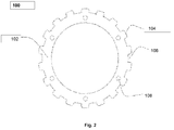
- Fig. 2 illustrates the sheath having the plurality of ribs and the plurality of grooves on the external surface of the sheath and strength members embedded inside the sheath in accordance with a second configuration of the present disclosure.
- the plurality of ribs 104 in the sheath 102 is 18.
- the plurality of ribs 104 in the sheath 102 may vary.
- the plurality of grooves 106 in the sheath 102 is 18.
- the plurality of grooves 106 may vary.
- the area of the ribbed and grooved optical fiber cable 100 corresponding to 18 ribs and 18 grooves is about 44.28 millimeter square.
- area of the cable may vary depending upon internal diameter of the cable, external diameter of the cable, number of the plurality of ribs 104 and the plurality of grooves 106.
- the ribbed and grooved optical fiber cable 100 has deformation of about 0.63 under crushing load at 500 Newton per 100 millimeter. Alternatively, deformation of the ribbed and grooved optical fiber cable 100 may vary. In addition, deformation of the ribbed and grooved optical fiber cable 100 may vary depending upon the plurality of parameters.
- the plurality of parameters includes but may not be limited to number of the plurality of ribs 104 and the plurality of grooves 106, width and height of the plurality of ribs 104 and the plurality of grooves 106, inside and outside diameter of the ribbed and grooved optical fiber cable 100, number of the plurality of strength members 108 in the sheath 102, and material grade of the ribbed and grooved optical fiber cable 100.
- the plurality of ribs (i.e. the plurality of external ribs) 104 and the plurality of grooves (i.e. the plurality of external grooves) 106 are arranged alternately to each other on the outer surface of the sheath 102.
- a groove of the plurality of grooves 106 is present on both sides of each rib of the plurality of ribs 104.
- a rib of the plurality of ribs 104 is present on both sides of each groove of the plurality of grooves 106.
- height of each of the plurality of ribs 104 is equal.
- height of each of the plurality of grooves 106 is equal.
- the plurality of ribs 104 and the plurality of grooves 106 may have any shape including but not limited to arc, rectangular, square, triangular, trapezoidal etc.
- Fig. 3 illustrates the sheath of the cable with the plurality of ribs of different heights in accordance with an embodiment of the present disclosure.
- the plurality of ribs 104 includes a first type of ribs and a second type of ribs.
- Each rib of the first type of ribs has a large size.
- Each rib of the second type of ribs has a smaller size as compared to the first type of ribs.
- height of the first type of ribs i.e. a first height
- height of the second type of ribs i.e. a second height
- the first type of ribs touches the duct.
- the second type of ribs does not touch the duct due to the small size of the second type of ribs.
- the number of the first type of ribs is equal to the number of the second type of ribs.
- the first type of ribs and the second type of ribs are arranged alternately to each other.
- the alternate arrangement of the first type of ribs and the second type of ribs reduces weight of the ribbed and grooved optical fiber cable 100.
- the alternate arrangement of the first type of ribs and the second type of ribs reduces friction in the ribbed and grooved optical fiber cable 100.
- the number of the first type of ribs is 6. In another embodiment of the present disclosure, the number of the first type of ribs may vary.
- the number of the second type of ribs is 6. In another embodiment of the present disclosure, the number of the second type of ribs may vary. In an embodiment of the present disclosure, the plurality of ribs 104 (first type of ribs and second type of ribs) is 12. In another embodiment of the present disclosure, the number of the plurality of ribs 104 may vary.
- the area of the ribbed and grooved optical fiber cable 100 corresponding to 12 ribs is about 43.66 millimeter square.
- the area of the ribbed and grooved optical fiber cable 100 may vary depending upon internal diameter of the cable, external diameter of the cable, number of the plurality of ribs 104.
- the ribbed and grooved optical fiber cable 100 has deformation of about 0.59 under crushing load at 500 Newton per 100 millimeter. In another embodiment of the present disclosure, deformation of the ribbed and grooved optical fiber cable 100 may vary. In addition, deformation of the ribbed and grooved optical fiber cable 100 may vary depending upon the plurality of parameters.
- the plurality of parameters includes but may not be limited to number of the plurality of ribs 104 and the plurality of grooves 106, width and height of the plurality of ribs 104 and the plurality of grooves 106, inside and outside diameter of the ribbed and grooved optical fiber cable 100 , number of the plurality of strength members 108 in the sheath 102, and material grade of the ribbed and grooved optical fiber cable 100.
- Fig. 4 illustrates the sheath of the cable having a plurality of internal grooves, a plurality of external grooves, a plurality of internal ribs and a plurality of external ribs in accordance with an embodiment of the present disclosure.
- the sheath 102 has the plurality of ribs 104, the plurality of grooves 106, and the plurality of strength members 108.
- the plurality of ribs 104 is formed on the outer surface of the sheath 102 and may be referred to as the plurality of external ribs.
- the sheath 102 includes a plurality of internal ribs 104a and a plurality of internal grooves 106a formed on an internal surface of the sheath 102.
- the number of the plurality of ribs 104 on the outer surface of the sheath 102 of the ribbed and grooved optical fiber cable 100 is 12.
- the number of the plurality of ribs 104 on the outer surface of the sheath 102 of the ribbed and grooved optical fiber cable 100 may vary.
- Each of the plurality of ribs 104 has height of about 0.5 millimeter. Alternatively, height of the plurality of ribs 104 may vary.
- the sheath 102 includes the plurality of grooves 106, and the plurality of grooves 106 is also called the plurality of external grooves. Further, the sheath 102 includes a plurality of internal grooves 106a formed on an inner/internal surface of the sheath 102.
- the plurality of internal grooves 106a reduces the mass of the ribbed and grooved optical fiber cable 100. In addition, the plurality of internal grooves 106a increases free space for optical fibers or ribbons in the ribbed and grooved optical fiber cable 100.
- the plurality of external grooves 106 is formed on the outer surface of the sheath 102.
- the plurality of internal grooves 106a on the inner surface of the sheath 102 is 6.
- the plurality of internal grooves 106a on the inner surface of the sheath 102 may vary.
- the plurality of internal grooves 106a has a depth of about 0.5 millimeter.
- the depth of the plurality of internal grooves 106a may vary.
- the plurality of external grooves 106 on the outer surface of the sheath 102 is 12.
- the plurality of external grooves 106 on the outer of the sheath 102 may vary.
- the area of the ribbed and grooved optical fiber cable 100 corresponding to 12 external ribs and 6 internal grooves is about 41.05 millimeter square.
- area of the cable may vary depending upon internal diameter of the cable, external diameter of the cable, number of the plurality of ribs 104.
- the ribbed and grooved optical fiber cable 100 has deformation of about 1.80 millimeter under crushing load at 500 Newton per 100 millimeter.
- deformation of the ribbed and grooved optical fiber cable 100 may vary.
- deformation of the ribbed and grooved optical fiber cable 100 may vary depending upon the plurality of parameters.
- the plurality of parameters includes but may not be limited to number of the plurality of ribs 104 and number of the plurality of internal grooves 106a and the plurality of external grooves 106, width and height of the plurality of ribs 104 and the plurality of grooves 106, inside and outside diameter of the ribbed and grooved optical fiber cable 100 , number of the plurality of strength members 108 in the sheath 102, and material grade of the ribbed and grooved optical fiber cable 100.
- Fig. 5 illustrates the sheath of the cable having embedded strength members in accordance with an embodiment of the present disclosure.
- the plurality of ribs 104 includes a first type of ribs and a second type of ribs.
- Each rib of the first type of ribs has a large size.
- Each rib of the second type of ribs has a smaller size as compared to the first type of ribs.
- height of the first type of ribs i.e. the first height
- height of the second type of ribs i.e. the second height
- the number of the first type of ribs is equal to the number of the second type of ribs.
- the first type of ribs and the second type of ribs are arranged alternately to each other.
- the alternate arrangement of the first type of ribs and the second type of ribs reduce weight of the ribbed and grooved optical fiber cable 100.
- the alternate arrangement of the first type of ribs and the second type of ribs reduces friction in the ribbed and grooved optical fiber cable 100.
- the number of the first type of ribs is 9.
- the number of the first type of ribs may vary.
- the number of the second type of ribs is 9.
- the number of the second type of ribs may vary.
- the plurality of ribs 104 (first type of ribs and second type of ribs) is 18. Alternatively, the plurality of ribs 104 may vary. Further, the plurality of grooves 106 in the ribbed and grooved optical fiber cable 100 is 18. Alternatively, the plurality of grooves 106 may vary. In an embodiment of the present disclosure, the area of the ribbed and grooved optical fiber cable 100 corresponding to 18 ribs is about 42.17 millimeter square. Alternatively, area of the ribbed and grooved optical fiber cable 100 may vary depending upon internal diameter of the cable, external diameter of the cable, number of the plurality of ribs 104. The ribbed and grooved optical fiber cable 100 has deformation of about 0.45 millimeter under crushing load at 500 Newton per 100 millimeter. Alternatively, deformation of the ribbed and grooved optical fiber cable 100 may vary.
- deformation of the ribbed and grooved optical fiber cable 100 may vary depending upon the plurality of parameters.
- the plurality of parameters includes but may not be limited to number of the plurality of ribs 104 and number of internal grooves of the plurality of grooves 106, width and height of the plurality of ribs 104 and the plurality of grooves 106, inside and outside diameter of the ribbed and grooved optical fiber cable 100, number of the plurality of strength members 108 in the sheath 102, and material grade of the ribbed and grooved optical fiber cable 100.
- the plurality of ribs 104 and the plurality of grooves 106 of the ribbed and grooved optical fiber cable 100 are arranged alternately to each other on the outer surface of the sheath 102.
- height of the first type of ribs of the ribbed and grooved optical fiber cable 100 i.e. the first height is 0.5 millimeter.
- the height of the second type of ribs of the ribbed and grooved optical fiber cable 100 i.e. the second height is 0.25 millimeter.
- height of the first type of ribs (i.e. the first height) of the ribbed and grooved optical fiber cable 100 may vary.
- height of the second type of ribs (i.e. the second height) of the ribbed and grooved optical fiber cable 100 may vary.
- first type of ribs and the second type of ribs enables high crushing performance.
- first type of ribs support the second type of ribs when a fixed crush load is applied on the ribbed and grooved optical fiber cable 100 that enables high crushing performance as compared to the similar design of cable where all the ribs have equal height.
- the number of the first type of ribs and the second type of ribs is an odd number.
- the odd number of the first type of ribs and the second type of ribs ensures that each of the first type of ribs is diametrically opposite to the corresponding rib of the second type of ribs.
- the odd number of the first type of ribs and the second type of ribs eliminates dependency on orientation of the fixed crush load on the ribbed and grooved optical fiber cable 100.
- the sheath 102 having more number of the first type of ribs (large sized ribs) has small lateral deformations. Adjacent ribs provide support to the cross section of the ribbed and grooved optical fiber cable 100 when the cable starts to deform and take an elliptical shape.
- the sheath 102 has less plurality of ribs 104. The plurality of ribs 104 are more spaced out in the sheath 102 due to less number of plurality of ribs 104.
- the sheath 102 with less plurality of ribs 104 does not provide support to the cross section of the ribbed and grooved optical fiber cable 100 even at low forces.
- Fig. 6 illustrates the sheath of the cable having the plurality of grooves and the plurality of ribs extruded in a linear manner along a length of the cable in accordance with an embodiment of the present disclosure.
- the plurality of ribs 104 and the plurality of grooves 106 are extruded longitudinally along the length of the ribbed and grooved optical fiber cable 100.
- Fig. 7 illustrates the sheath of the cable having the plurality of grooves and the plurality of ribs extruded helically along the length of the cable in accordance with an embodiment of the present disclosure.
- the plurality of ribs 104 and the plurality of grooves 106 are extruded helically along the length of the ribbed and grooved optical fiber cable 100.
- the plurality of ribs 104 and the plurality of grooves 106 are extruded in SZ fashion.
- the plurality of ribs 104 and the plurality of grooves 106 may be extruded in any suitable shape.
- Fig. 8 illustrates the sheath of the cable having the plurality of internal grooves, the plurality of external grooves, the plurality of internal ribs and the plurality of external ribs in accordance with an embodiment of the present disclosure.
- the sheath 102 includes the plurality of ribs 104 on the external surface of the sheath (referred to as the plurality of external ribs 104 with reference to Fig. 8 ), the plurality of grooves 106 on the external surface of the sheath (referred to as the plurality of external grooves 106 with reference to Fig. 8 ), the plurality of internal ribs 104a, the plurality of internal grooves 106a and the plurality of strength members 108.
- the plurality of ribs 104 includes the first type of ribs and the second type of ribs.
- Each rib of the first type of ribs has a large size.
- Each rib of the second type of ribs has a smaller size as compared to the first type of ribs.
- the height of each of the first type of ribs i.e. the first height
- the height of each of the second type of ribs is larger than the height of each of the second type of ribs (i.e. the second height).
- the number of the first type of ribs is equal to the number of the second type of ribs.
- the first type of ribs and the second type of ribs are arranged alternately to each other.
- the alternate arrangement of the first type of ribs and the second type of ribs reduces weight of the ribbed and grooved optical fiber cable 100.
- the alternate arrangement of the first type of ribs and the second type of ribs reduces friction in the ribbed and grooved optical fiber cable 100.
- the number of the first type of ribs is 6.
- the number of the first type of ribs may vary.
- the number of the second type of ribs is 6.
- the number of the second type of ribs may vary.
- the plurality of ribs 104 (first type of ribs and second type of ribs) is 12.
- the plurality of ribs 104 may vary.
- the ribbed and grooved optical fiber cable 100 includes the plurality of external grooves 106.
- the plurality of grooves 106a corresponds to the internal grooves.
- the plurality of ribs 104 surrounds the plurality of grooves 106.
- the plurality of grooves 106a (the internal grooves) are formed on the inner surface of the sheath 102. Further, the number of the internal grooves on the inner surface of the sheath 102 is 6. Alternatively, the number of the internal grooves on the inner surface of the sheath 102 may vary.
- the first height may be in a range of 0.2-1.0 millimeter (mm) and the second height may be in the range of 0.1-0.5 millimeter.
- the first height may be in the range of 0.1-0.5 millimeter and the second height may be in the range of 0.2-1.0 millimeter.
- the plurality of ribs 104 may have a width in the range of 0.8-6.5 millimeter.
- the plurality of grooves 106 may have a width in the range of 0.8-6.5 millimeter.
- the alternate arrangement of the first type of ribs and the second type of ribs enables high crushing performance.
- the first type of ribs support the second type of ribs when a fixed crush load is applied on the ribbed and grooved optical fiber cable 100 that enables high crushing performance as compared to the similar design of cable where all the ribs have equal height.
- the number of the first type of ribs and the second type of ribs is an odd number.
- the odd number of the first type of ribs and the second type of ribs ensures that each of the first type of ribs is diametrically opposite to the corresponding rib of the second type of ribs. Moreover, the odd number of the first type of ribs and the second type of ribs eliminates dependency on orientation of the fixed crush load on the ribbed and grooved optical fiber cable 100.
- Fig. 9 illustrates the strength member of the cable coated with a coating material in accordance with an embodiment of the present disclosure.
- the plurality of strength members 108 embedded in the sheath 102 may have a circular shape or any other suitable shape.
- the one or more strength members 108 are coated with the coating material having at least one of an ultraviolet (UV) curable water swellable resin composition (or resin) and a thick layer of ethylene acrylic acid (EAA) to prevent water ingression in the ribbed and grooved optical fiber cable 100 as without the coating material, the water may seep through the one or more strength members 108 embedded in the sheath 102.
- UV ultraviolet
- EAA ethylene acrylic acid
- the thick layer of ethylene acrylic acid (EAA) 202 may be coated on the one or more strength members 200 before embedding in the sheath 102.
- the ethylene acrylic acid (EAA) provides a good adhesion between the one or more strength members 108 and the sheath 102 to further prevent from water ingression.
- the UV curable water swellable resin composition 202 is coated on the one or more strength members 200 and cured before embedding in the sheath 102.
- the resin composition comes in contact with water, it swells and blocks the way for water to avoid penetration in the core of the ribbed and grooved optical fiber cable 100.
- the core includes the plurality of optical fibers.
- the plurality of optical fibers may be incorporated in the core as a plurality of loose tube optical fibers, a plurality of tight buffered optical fibers, a group or stack of optical fiber ribbons or the like., which is enclosed by the sheath 102.
- the UV curable water swellable resin composition can include, but not limited to, acrylic acid, phenyl bis(2,4,6-trimethylbenzoyl)-phosphine oxide and oxybis(methyl-2,1-ethanediyl) diacrylate.
- the UV curable water swellable resin composition may be applied directly on the one or more strength members 108 or above a thin layer of ethylene acrylic acid (EAA) having a thickness of 25 ⁇ 5 microns.
- EAA ethylene acrylic acid
- the thin layer of ethylene acrylic acid (EAA) helps to achieve better adhesion of the one or more strength members with material of the sheath.
- the coating 202 may have a thickness, preferably, in a range of 40 microns to 60 microns as a thinner layer of the coating material may lead to water ingression.
- a sheathing tool has strength member embedding holes that supports the coating thickness upto 50-60 microns. Beyond this, abrasion will occur and will further lead to waste creation.
- the thickness of the coating may vary.
- the one or more strength members 108 may be made of fiber reinforced plastic (FRP), aramid reinforced plastic (ARP) or any other suitable material.
- Figs. 1 to 8 illustrate the sheath of the cable in accordance with various embodiments of the present disclosure.
- the sheath 102 has the plurality of ribs 104, the plurality of grooves 106 and the plurality of strength members 108.
- the sheath 102 encloses the plurality of optical fibers.
- the plurality of grooves 106 on the outer surface of the sheath 102 may be called as the plurality of external grooves or external grooves.
- the plurality of grooves 106 on the inner surface of the sheath 102 may be called as the plurality of internal grooves or internal grooves.
- the plurality of ribs 104 on the outer surface of the sheath 102 may be called as the plurality of external ribs or external ribs.
- the plurality of ribs 104a on the inner surface of the sheath 102 may be called as the plurality of internal ribs or internal ribs.
- the plurality of ribs 104 includes a first type of ribs and a second type of ribs.
- Each rib of the first type of ribs may have a larger size than each rib of the second type of ribs.
- each rib of the first type of ribs may have smaller size than each rib of the second type of ribs.
- the ribbed and grooved optical fiber cable 100 having the plurality of ribs 104 may have at least two heights.
- the first type of ribs may have the first height and the second type of ribs may have the second height.
- the first type of ribs may have a larger height than of the second type of ribs.
- the first type of ribs may have smaller height than of the second type of ribs.
- the first type of ribs and the second type of ribs may have the same size and height.
- the plurality of ribs 104 and the plurality of grooves 106 of the ribbed and grooved optical fiber cable 100 are arranged alternately to each other on the outer surface of the sheath 102.
- the height (i.e. the first height) of the first type of ribs and the height (i.e. the second height) of the second type of ribs of the ribbed and grooved optical fiber cable 100 may vary.
- height of each of the plurality of grooves 106 is equal.
- height of each of the plurality of grooves 106 may vary.
- the sheath 102 having more number of the first type of ribs has small lateral deformations. Adjacent ribs provide support to the cross section of the ribbed and grooved optical fiber cable 100 when the cable starts to deform and take an elliptical shape.
- the sheath 102 has less plurality of ribs 104. The plurality of ribs 104 are more spaced out in the sheath 102 due to less number of plurality of ribs 104.
- the sheath 102 with less plurality of ribs 104 does not provide support to the cross section of the ribbed and grooved optical fiber cable 100 even at low forces.
- Fig. 10 illustrates a water penetration test arrangement for the cable in accordance with an embodiment of the present disclosure.
- the sample was pre-soaked in a bucket of water to a depth of 100 mm ⁇ 10 mm for 10 min before the test.
- the cable sample 302 of 3 meters was taken and a watertight seal 304 was applied to allow a 1m (H) of water-head 306 to be applied for 24 hours.
- the sheath 102 and the plurality of external ribs 104 may be made of same material such as polyvinyl chloride, polyethylene (such as High Density Polyethylene (HDPE), Medium Density Polyethylene, and Low Density Polyethylene), polyurethane, thermoplastic rubber/elastomer, thermoplastic chlorinated polyethylene, thermoset polyolefins or combination thereof.
- polyvinyl chloride such as High Density Polyethylene (HDPE), Medium Density Polyethylene, and Low Density Polyethylene
- polyurethane such as High Density Polyethylene (HDPE), Medium Density Polyethylene, and Low Density Polyethylene
- thermoplastic rubber/elastomer such as thermoplastic rubber/elastomer, thermoplastic chlorinated polyethylene, thermoset polyolefins or combination thereof.
- the sheath 102 and the plurality of external ribs 104 may be made of different materials.
- the plurality of external ribs 104 and the plurality of external grooves 106 are one or more of a rectangular shape with rounded edges, a pointy triangle shape, a circular shape, a curve-type shape or other suitable shape. Further, the plurality of external ribs 104 has a height (first height or second height or both) in a range of 0.1-2.0 millimeters, the plurality of external ribs 104 has a width in a range of 0.4-20 millimeters and the plurality of external grooves 106 has a width in a range of 0.4-20 millimeters.
- the optical fiber ribbed and grooved optical fiber cable 100 has a diameter in a range of 11 to 13 millimeters, and the optical fiber cable has a blowing of more than 1100 meters in the duct with an inner diameter of 14 millimeters and an outer diameter of 18 millimeters.
- the plurality of internal ribs have the height in the range of 0.1-1.0 millimeter and the width in the range of 1.2-2.5 millimeters. Further, the plurality of internal grooves have the width in the range of 1.2-2.5 millimeters.
- the ribbed and grooved cable that reduces coefficient of friction between a cable sheath and a duct.
- the ribbed and grooved cable has embedded strength member(s) in the cable sheath with a water blocking coating to provide mechanical strength and ease of blowing to the ribbed and grooved cable and to prevent water ingression inside the ribbed and grooved cable.
- the inner grooves reduce mass of the ribbed and grooved cable while increasing free space for optical fibers or ribbons in the ribbed and grooved cable.
- the present disclosure provides advantages such as a high blowing performance, reduced mass of the cable, increased free space for optical fibers or ribbons in the cable, large and irregular surface area, increased drag force, reduced coefficient of friction between the sheath and the duct, and better crushing behaviour.
- Disjunctive language such as the phrase "at least one of X, Y, Z," unless specifically stated otherwise, is otherwise understood with the context as used in general to present that an item, term, etc., may be either X, Y, or Z, or any combination thereof (e.g., X, Y, and/or Z). Thus, such disjunctive language is not generally intended to, and should not, imply that certain embodiments require at least one of X, at least one of Y, or at least one of Z to each be present.
Abstract
Description
- Embodiments of the present disclosure relate to a field optical communication technology. And more particularly, relates to a ribbed and grooved optical cable.
- This application claims the benefit of
Indian Application No. 202011024930 "Ribbed and Grooved Cable" filed by the applicant on 13/06/2020 Indian Application Number 202011045978 filed by the applicant on 22/10/2020 - With technological and scientific advancements, various modern communication technologies have been introduced and employed. One of the most important modern communication technologies is optical fiber communication technology using a variety of optical fiber cables. The optical fiber cables are widely used for communication to meet the increasing demands of end-users. To meet the increasing demands, installation of the optical fiber cables at a rapid pace becomes essential. The optical fiber cables for telecommunication application are installed in ducts. The installation of the optical fiber cables in the ducts is mostly performed using a blowing method, wherein, the blowing method to install the optical fiber cables in the ducts is dependent on a plurality of factors. The plurality of factors includes mass of the optical fiber cable, friction, stiffness, and the like. The blowing method enables installation of the optical fiber cable using pressurized air combined with additional mechanical pushing force that is called "blowing".
- In general, the blowing method is the process of installation of the optical fiber cable into a pre-installed duct. The blowing is performed by injecting pressurized air inlet of the pre-installed duct before the optical fiber cable is pushed into the pre-installed duct. The pressurized air flows at high speed through the pre-installed duct and along the optical fiber cable. Also, pushing force is applied near the optical fiber cable inlet by a pushing device. The optical fiber cable includes uni-tube, multi-tube, unarmoured, armoured, micro duct cable, and the like. However, conventional structure of optical fiber cable makes it inefficient to allow pressurized air to blow the optical fiber cable in the pre-installed duct. In addition, the conventional optical fiber cable resists the pushing force due to higher coefficient of friction. Further, the conventional optical fiber cable has a higher number of contact points with the pre-installed duct. Furthermore, the conventional optical fiber cable has heavy weight.
- Additionally, strength members are one of the important components of the optical fiber cable. The purpose of the strength members is to provide the optical fiber cable rigidity, bend resistance, mechanical strength and ease in blowing. A strength member can be installed either at a center of the optical fiber cable or embedded inside the sheath of the optical fiber cable. The strength member embedded inside the sheath is normally preferred over a central strength member for making a high density optical fiber cable as there is more space available in the center. After embedding the strength member in the sheath of the optical fiber cable, often water penetration occurs through the embedded strength member. The main reason is, during the embedding of the strength member inside the sheath, some clearance remains between the strength member and the sheath due to manufacturing tolerances. Generally, the water may penetrate even through a clearance of a few dozen microns. A water penetration test of the optical fiber cable is often carried out to assess the ability of the optical fiber cable to resist the water penetration in the optical fiber cable. Such water penetration assessments are necessary because water once penetrated through the clearance between the strength member and the sheath due to manufacturing tolerances, may travel to optical fiber junction boxes and may degrade optical properties of the components such as optical fibers. Also, water penetration through a length of the optical fiber cable further leads to degradation of other components of the optical network.
- A prior-art reference "
WO2020075734A1 " discloses an optical fiber cable having a plurality of ribs on the surface of the optical fiber cable for improved blowing performance, however the ribs are of the same height. - In view of the aforementioned discussion and prior-art reference, there is an urgent need for a technical solution that overcomes the above stated limitations of the prior arts of the conventional optical fiber cable. Hence, the present disclosure focuses on a ribbed and grooved cable having embedded strength members with water blocking coating. Any references to methods, apparatus or documents of the prior art are not to be taken as constituting any evidence or admission that they formed, or form part of the common general knowledge.
- Embodiments of the present disclosure provide a ribbed and grooved cable having embedded strength members with water blocking coating.
- According to a first aspect, the ribbed grooved optical fiber cable includes a core with a plurality of optical fibers, a sheath enveloping the core and the sheath has an outer surface and an inner surface, the outer surface of the sheath has a plurality of external ribs and a plurality of external grooves and one or more strength members embedded in the sheath. In particular, the one or more strength members are coated with a water blocking coating material having at least one of an ultraviolet (UV) curable water swellable resin composition and a layer of ethylene acrylic acid (EAA).
- According to the second aspect of the present disclosure, the UV curable water swellable resin composition includes acrylic acid, phenyl bis(2,4,6-trimethylbenzoyl)-phosphine oxide and oxybis(methyl-2,1-ethanediyl) diacrylate. In accordance with an embodiment of the present disclosure, the UV curable water swellable resin composition is applied directly on the one or more strength members or above a thin layer of ethylene acrylic acid (EAA). In accordance with an embodiment of the present disclosure, the UV curable water swellable resin composition coated one or more strength members are passed through one or more UV chambers to cure the UV curable water swellable resin composition.
- According to the third aspect of the present disclosure, the water blocking coating material applied over the one or more strength members has a thickness of 50±10 microns. In accordance with an embodiment of the present disclosure, the one or more strength members are made of a fiber reinforced plastic (FRP), an aramid reinforced plastic (ARP) or alike material.
- According to the fourth aspect of the present disclosure, the plurality of external ribs are arranged alternately throughout the outer surface of the sheath of the ribbed grooved optical fiber cable.
- According to the fifth aspect of the present disclosure, the plurality of external ribs having the first height and the second height are arranged in such a way that the plurality of external ribs having the first height and the plurality of external ribs having the second height are positioned diagonally opposite to each other. In accordance with an embodiment of the present disclosure, the plurality of external ribs of the sheath have at least two heights including a first height and a second height.
- According to the sixth aspect of the present disclosure, the first height is in a range of 0.2 millimeters to 1.0 millimeters and the second height is in the range of 0.1 millimeters to 0.5 millimeters. In accordance with an embodiment of the present disclosure, the plurality of external ribs and the plurality of external grooves has a width in the range of 1.2 millimeters to 2.5 millimeters.
- According to the seventh aspect of the present disclosure, the shape of the plurality of external ribs and the plurality of external grooves is any rectangular shape with rounded edges, a pointy triangle shape, a circular shape, a curve-type shape or any suitable shape.
- According to the eighth aspect of the present disclosure, the sheath and the plurality of external ribs are made of a same material. In accordance with an embodiment of the present disclosure, the sheath and the plurality of external ribs are made of different materials.
- According to the ninth aspect of the present disclosure, the ribbed grooved optical fiber cable has a diameter in the range of 11 to 13 millimeters and has a blowing of more than 1100 meters in a duct with an inner diameter of 14 millimeters and an outer diameter of 18 millimeters.
- According to the tenth aspect of the present disclosure, the plurality of internal ribs and the plurality of internal grooves are arranged alternately throughout the inner surface of the sheath. In accordance with an embodiment of the present disclosure, the plurality of internal grooves is made to reduce weight of the ribbed grooved optical fiber cable. According to an aspect of the present disclosure, a shape of the plurality of internal ribs and the plurality of internal grooves has a rectangular shape with rounded edges, a pointy triangle shape, a circular shape, a curve-type shape or alike shape. In accordance with an embodiment of the present disclosure, the plurality of internal ribs has a height in a range of 0.1 millimeter to 1.0 millimeter. In accordance with an embodiment of the present disclosure, the plurality of internal ribs and the plurality of internal grooves has a width in the range of 1.2 millimeter to 2.5 millimeters.
- According to another aspect of the present disclosure, the sheath used in the ribbed grooved optical fiber cable passes a water penetration test at 0.1 bar pressure water-head applied to a 3 meter optical cable for at least 24 hours.
- The foregoing solutions of the present disclosure are attained by employing a ribbed grooved optical fiber cable with embedded strength members coated with a water blocking coating material.
- To describe the technical solutions in the embodiments of the present disclosure or in the prior art more clearly, the following briefly describes the accompanying drawings required for describing the embodiments or the prior art. Apparently, the accompanying drawings in the following description merely show some embodiments of the present disclosure, and a person of ordinary skill in the art can derive other implementations from these accompanying drawings without creative efforts. All of the embodiments or the implementations shall fall within the protection scope of the present disclosure.
-
Fig. 1 illustrates a sheath of a ribbed grooved optical fiber cable having a plurality of ribs and a plurality of grooves on an external surface of the sheath and strength members embedded inside the sheath in accordance with a first configuration of the present disclosure; -
Fig. 2 illustrates the sheath having the plurality of ribs and the plurality of grooves on the external surface of the sheath and strength members embedded inside the sheath in accordance with a second configuration of the present disclosure; -
Fig. 3 illustrates the sheath with the plurality of ribs of different heights in accordance with an embodiment of the present disclosure; -
Fig. 4 illustrates the sheath having a plurality of internal grooves, a plurality of external grooves, a plurality of internal ribs and a plurality of external ribs in accordance with an embodiment of the present disclosure; -
Fig. 5 illustrates the sheath having embedded strength members in accordance with an embodiment of the present disclosure; -
Fig. 6 illustrates the sheath having the plurality of grooves and the plurality of ribs extruded in a linear manner along a length of the cable in accordance with an embodiment of the present disclosure; -
Fig. 7 illustrates the sheath having the plurality of grooves and the plurality of ribs extruded helically along the length of the cable in accordance with an embodiment of the present disclosure; -
Fig. 8 illustrates the sheath having the plurality of internal grooves, the plurality of external grooves, the plurality of internal ribs and the plurality of external ribs in accordance with an embodiment of the present disclosure; -
Fig. 9 illustrates the strength member of the ribbed grooved optical fiber cable coated with a coating material in accordance with an embodiment of the present disclosure; -
Fig. 10 illustrates a water penetration test arrangement for the ribbed grooved optical fiber cable in accordance with an embodiment of the present disclosure. -
- Ribbed Grooved
Optical Fiber Cable 100 -
Sheath 102 - Plurality Of
Ribs 104 - Plurality Of
Grooves 106 - Plurality Of
Internal Ribs 104a - Plurality Of
Internal Grooves 106a - Plurality Of
Coated Strength Members 108 -
Coating 202 -
Cable Sample 302 -
Watertight Seal 304 - Water-
head 306 - The ribbed and grooved cable and the sheath illustrated in the accompanying drawings, throughout which like reference letters indicate corresponding parts in the various figures.
- It should be noted that the accompanying figure is intended to present illustrations of exemplary embodiments of the present disclosure. This figure is not intended to limit the scope of the present disclosure. It should also be noted that the accompanying figure is not necessarily drawn to scale.
- Those skilled in the art will be aware that the present disclosure is subject to variations and modifications other than those specifically described. It is to be understood that the present disclosure includes all such variations and modifications. The disclosure also includes all such steps, features, compositions and compounds referred to or indicated in this specification, individually or collectively, and any and all combinations of any or more of such steps or features.
- For convenience, before further description of the present disclosure, certain terms employed in the specification, and examples are collected here. These definitions should be read in the light of the remainder of the disclosure and understood as by a person of skill in the art. The terms used herein have the meanings recognized and known to those of skill in the art, however, for convenience and completeness, particular terms and their meanings are set forth below.
- The articles "a", "an" and "the" are used to refer to one or to more than one (i.e., to at least one) of the grammatical object of the article.
- The terms "comprise" and "comprising" are used in the inclusive, open sense, meaning that additional elements may be included. It is not intended to be construed as "consists of only". Throughout this specification, unless the context requires otherwise the word "comprise", and variations such as "comprises" and "comprising", will be understood to imply the inclusion of a stated element or step or group of element or steps but not the exclusion of any other element or step or group of element or steps.
- The term "including" is used to mean "including but not limited to". "Including" and "including but not limited to" are used interchangeably.
-
Fig. 1 illustrates a design of a sheath of an optical ribbed and grooved 100 having a plurality of ribs and a plurality of grooves on an external surface of the sheath and strength members embedded inside the sheath in accordance with the first configuration of the present disclosure. In particular, the cable is termed as a ribbed and groovedoptical fiber cable 100 as it has a ribbed and grooved sheath. Moreover, the ribbed and groovedoptical fiber cable 100 includes a plurality of optical fibers (not shown) and thesheath 102 having a plurality ofribs 104 and a plurality ofgrooves 106. Moreover, thesheath 102 has a plurality ofstrength members 108 embedded into it. - The
sheath 102 includes an inner surface and an outer surface. In particular, sheath is an outer layer of a ribbed groovedoptical fiber cable 100 protects the optical fiber cable from environmental conditions. In addition, the environment conditions include but may not be limited to rainfall, sunlight, snowfall, and wind. Moreover, thesheath 102 of the ribbed and groovedoptical fiber cable 100 encloses the plurality of optical fibers concentrically along a length of the optical fiber cable. Further, the sheath has an outer surface and an inner surface. The outer surface of thesheath 102 of the ribbed and groovedoptical fiber cable 100 includes the plurality ofribs 104 and the plurality ofgrooves 106. The plurality ofribs 104 and the plurality ofgrooves 106 are formed on the outer surface of thesheath 102, thus called as a plurality of external ribs and a plurality of external grooves throughout the disclosure. - In an embodiment of the present disclosure, the number of the plurality of
ribs 104 is the same as the number of the plurality ofgrooves 106. In one embodiment of the present disclosure, each of the plurality ofribs 104 has depth in range of about 0.1 millimeter to 2 millimeters. In another embodiment of the present disclosure, the plurality ofribs 104 has depth in range of about 0.2 millimeter to 1 millimeter. - In yet another embodiment of the present disclosure, depth of the plurality of
ribs 104 may vary. In an embodiment of the present disclosure, the plurality ofribs 104 has width in range of about 0.4 millimeter to 20 millimeter. In another embodiment of the present disclosure, the plurality ofribs 104 has width in range of about 0.5 millimeter to 4 millimeter. In yet another embodiment of the present disclosure, width of the plurality ofribs 104 may vary. In one aspect of the present disclosure, the plurality ofribs 104 may be 12. In another aspect of the present disclosure, the plurality ofribs 104 may vary depending upon the width of the plurality ofribs 104. In an embodiment of the present disclosure, the number ofgrooves 106 is 12. In another embodiment of the present disclosure, the plurality ofgrooves 106 may vary depending upon width of the plurality ofgrooves 106. - In one aspect of the present disclosure, the area of the ribbed and grooved
optical fiber cable 100 corresponding to 12 ribs and 12 grooves is about 44.45 millimeter square. In another aspect of the present disclosure, the area of the cable may vary depending upon internal diameter of the cable, external diameter of the cable, number of the plurality ofribs 104 and the plurality ofgrooves 106. - In an aspect of the present disclosure, the ribbed and grooved
optical fiber cable 100 has deformation of about 0.59 under crushing load at 500 Newton per 100 millimeter. In another aspect of the present disclosure, the deformation of the ribbed and groovedoptical fiber cable 100 may vary. In particular, deformation of the ribbed and groovedoptical fiber cable 100 may vary depending upon a plurality of parameters. And, the plurality of parameters includes but may not be limited to number of the plurality ofribs 104 and the plurality ofgrooves 106, width and height of the plurality ofribs 104 and the plurality ofgrooves 106, inside and outside diameter of the ribbed and groovedoptical fiber cable 100, number of the plurality ofstrength members 108 in thesheath 102, and material grade of the ribbed and groovedoptical fiber cable 100. - The plurality of
ribs 104 and the plurality ofgrooves 106 reduce coefficient of friction between thesheath 102 and a duct. In an embodiment of the present disclosure, the plurality ofribs 104 and the plurality ofgrooves 106 are arranged alternately to each other on the outer surface of thesheath 102. In an exemplary example, a groove of the plurality ofgrooves 106 is present on both sides of each rib of the plurality ofribs 104. In another exemplary example, a rib of the plurality ofribs 104 is present on both sides of each groove of the plurality ofgrooves 106. In an embodiment of the present disclosure, the height of each of the plurality ofribs 104 is equal. Alternatively, in another embodiment, height of each of the plurality ofgrooves 106 is equal. - In an embodiment of the present disclosure, the ribbed and grooved
optical fiber cable 100 is installed into the duct using a blowing process. Particularly, the duct surrounds the ribbed and groovedoptical fiber cable 100. The blowing process to install the ribbed and groovedoptical fiber cable 100 in the duct is dependent on a plurality of factors. Moreover, the plurality of factors includes mass of the ribbed and groovedoptical fiber cable 100, friction between the ribbed and groovedoptical fiber cable 100 and the duct, stiffness of the ribbed and groovedoptical fiber cable 100, and the like. Also, the blowing process enables installation of the ribbed and groovedoptical fiber cable 100 using pressurized air combined with a mechanical pushing force. Further, the ribbed and groovedoptical fiber cable 100 includes the plurality ofstrength members 108. Furthermore, each of the plurality ofstrength members 108 is embedded in thesheath 102. - In an embodiment of the present disclosure, each of the plurality of
strength elements 108 in thesheath 102 may be positioned differently. Particularly, the plurality ofstrength members 108 enhances blowing performance of the ribbed and groovedoptical fiber cable 100 by increasing stiffness of the ribbed and groovedoptical fiber cable 100. Moreover, the plurality ofstrength members 108 provides tensile strength to the ribbed and groovedoptical fiber cable 100. In an embodiment of the present disclosure, the plurality ofstrength members 108 embedded in thesheath 102 of the ribbed and groovedoptical fiber cable 100 is in the range of 4 to 18. In another embodiment of the present disclosure, the number of the plurality ofstrength members 108 may vary. -
Fig. 2 illustrates the sheath having the plurality of ribs and the plurality of grooves on the external surface of the sheath and strength members embedded inside the sheath in accordance with a second configuration of the present disclosure. The plurality ofribs 104 in thesheath 102 is 18. Alternatively, the plurality ofribs 104 in thesheath 102 may vary. In an embodiment of the present disclosure, the plurality ofgrooves 106 in thesheath 102 is 18. Alternatively, the plurality ofgrooves 106 may vary. In an embodiment of the present disclosure, the area of the ribbed and groovedoptical fiber cable 100 corresponding to 18 ribs and 18 grooves is about 44.28 millimeter square. In particular, area of the cable may vary depending upon internal diameter of the cable, external diameter of the cable, number of the plurality ofribs 104 and the plurality ofgrooves 106. - The ribbed and grooved
optical fiber cable 100 has deformation of about 0.63 under crushing load at 500 Newton per 100 millimeter. Alternatively, deformation of the ribbed and groovedoptical fiber cable 100 may vary. In addition, deformation of the ribbed and groovedoptical fiber cable 100 may vary depending upon the plurality of parameters. The plurality of parameters includes but may not be limited to number of the plurality ofribs 104 and the plurality ofgrooves 106, width and height of the plurality ofribs 104 and the plurality ofgrooves 106, inside and outside diameter of the ribbed and groovedoptical fiber cable 100, number of the plurality ofstrength members 108 in thesheath 102, and material grade of the ribbed and groovedoptical fiber cable 100. - In an embodiment of the present disclosure, the plurality of ribs (i.e. the plurality of external ribs) 104 and the plurality of grooves (i.e. the plurality of external grooves) 106 are arranged alternately to each other on the outer surface of the
sheath 102. In an example, a groove of the plurality ofgrooves 106 is present on both sides of each rib of the plurality ofribs 104. In another example, a rib of the plurality ofribs 104 is present on both sides of each groove of the plurality ofgrooves 106. In an embodiment of the present disclosure, height of each of the plurality ofribs 104 is equal. Alternatively, height of each of the plurality ofgrooves 106 is equal. In an embodiment of the present disclosure, the plurality ofribs 104 and the plurality ofgrooves 106 may have any shape including but not limited to arc, rectangular, square, triangular, trapezoidal etc. -
Fig. 3 illustrates the sheath of the cable with the plurality of ribs of different heights in accordance with an embodiment of the present disclosure. In particular, the plurality ofribs 104 includes a first type of ribs and a second type of ribs. Each rib of the first type of ribs has a large size. Each rib of the second type of ribs has a smaller size as compared to the first type of ribs. In an embodiment of the present disclosure, height of the first type of ribs (i.e. a first height) is larger than height of the second type of ribs (i.e. a second height). In an example, during installation of the ribbed and groovedoptical fiber cable 100 into a duct, only the first type of ribs touches the duct. In addition, the second type of ribs does not touch the duct due to the small size of the second type of ribs. - In an embodiment of the present disclosure, the number of the first type of ribs is equal to the number of the second type of ribs. Particularly, the first type of ribs and the second type of ribs are arranged alternately to each other. The alternate arrangement of the first type of ribs and the second type of ribs reduces weight of the ribbed and grooved
optical fiber cable 100. Moreover, the alternate arrangement of the first type of ribs and the second type of ribs reduces friction in the ribbed and groovedoptical fiber cable 100. In an embodiment of the present disclosure, the number of the first type of ribs is 6. In another embodiment of the present disclosure, the number of the first type of ribs may vary. In an embodiment of the present disclosure, the number of the second type of ribs is 6. In another embodiment of the present disclosure, the number of the second type of ribs may vary. In an embodiment of the present disclosure, the plurality of ribs 104 (first type of ribs and second type of ribs) is 12. In another embodiment of the present disclosure, the number of the plurality ofribs 104 may vary. - In an embodiment of the present disclosure, the area of the ribbed and grooved
optical fiber cable 100 corresponding to 12 ribs is about 43.66 millimeter square. Particularly, the area of the ribbed and groovedoptical fiber cable 100 may vary depending upon internal diameter of the cable, external diameter of the cable, number of the plurality ofribs 104. - In an embodiment of the present disclosure, the ribbed and grooved
optical fiber cable 100 has deformation of about 0.59 under crushing load at 500 Newton per 100 millimeter. In another embodiment of the present disclosure, deformation of the ribbed and groovedoptical fiber cable 100 may vary. In addition, deformation of the ribbed and groovedoptical fiber cable 100 may vary depending upon the plurality of parameters. The plurality of parameters includes but may not be limited to number of the plurality ofribs 104 and the plurality ofgrooves 106, width and height of the plurality ofribs 104 and the plurality ofgrooves 106, inside and outside diameter of the ribbed and groovedoptical fiber cable 100 , number of the plurality ofstrength members 108 in thesheath 102, and material grade of the ribbed and groovedoptical fiber cable 100. -
Fig. 4 illustrates the sheath of the cable having a plurality of internal grooves, a plurality of external grooves, a plurality of internal ribs and a plurality of external ribs in accordance with an embodiment of the present disclosure. Thesheath 102 has the plurality ofribs 104, the plurality ofgrooves 106, and the plurality ofstrength members 108. The plurality ofribs 104 is formed on the outer surface of thesheath 102 and may be referred to as the plurality of external ribs. Further, thesheath 102 includes a plurality ofinternal ribs 104a and a plurality ofinternal grooves 106a formed on an internal surface of thesheath 102. - In an implementation, the number of the plurality of
ribs 104 on the outer surface of thesheath 102 of the ribbed and groovedoptical fiber cable 100 is 12. Alternatively, the number of the plurality ofribs 104 on the outer surface of thesheath 102 of the ribbed and groovedoptical fiber cable 100 may vary. - Each of the plurality of
ribs 104 has height of about 0.5 millimeter. Alternatively, height of the plurality ofribs 104 may vary. Thesheath 102 includes the plurality ofgrooves 106, and the plurality ofgrooves 106 is also called the plurality of external grooves. Further, thesheath 102 includes a plurality ofinternal grooves 106a formed on an inner/internal surface of thesheath 102. The plurality ofinternal grooves 106a reduces the mass of the ribbed and groovedoptical fiber cable 100. In addition, the plurality ofinternal grooves 106a increases free space for optical fibers or ribbons in the ribbed and groovedoptical fiber cable 100. The plurality ofexternal grooves 106 is formed on the outer surface of thesheath 102. - In an implementation, the plurality of
internal grooves 106a on the inner surface of thesheath 102 is 6. Alternatively, the plurality ofinternal grooves 106a on the inner surface of thesheath 102 may vary. The plurality ofinternal grooves 106a has a depth of about 0.5 millimeter. Alternatively, the depth of the plurality ofinternal grooves 106a may vary. In an implementation, the plurality ofexternal grooves 106 on the outer surface of thesheath 102 is 12. Alternatively, the plurality ofexternal grooves 106 on the outer of thesheath 102 may vary. Further, the area of the ribbed and groovedoptical fiber cable 100 corresponding to 12 external ribs and 6 internal grooves is about 41.05 millimeter square. Alternatively, area of the cable may vary depending upon internal diameter of the cable, external diameter of the cable, number of the plurality ofribs 104. The ribbed and groovedoptical fiber cable 100 has deformation of about 1.80 millimeter under crushing load at 500 Newton per 100 millimeter. Alternatively, deformation of the ribbed and groovedoptical fiber cable 100 may vary. In addition, deformation of the ribbed and groovedoptical fiber cable 100 may vary depending upon the plurality of parameters. The plurality of parameters includes but may not be limited to number of the plurality ofribs 104 and number of the plurality ofinternal grooves 106a and the plurality ofexternal grooves 106, width and height of the plurality ofribs 104 and the plurality ofgrooves 106, inside and outside diameter of the ribbed and groovedoptical fiber cable 100 , number of the plurality ofstrength members 108 in thesheath 102, and material grade of the ribbed and groovedoptical fiber cable 100. -
Fig. 5 illustrates the sheath of the cable having embedded strength members in accordance with an embodiment of the present disclosure. In particular, the plurality ofribs 104 includes a first type of ribs and a second type of ribs. Each rib of the first type of ribs has a large size. Each rib of the second type of ribs has a smaller size as compared to the first type of ribs. Further, height of the first type of ribs (i.e. the first height) is larger than height of the second type of ribs (i.e. the second height). - In an implementation, the number of the first type of ribs is equal to the number of the second type of ribs. The first type of ribs and the second type of ribs are arranged alternately to each other. The alternate arrangement of the first type of ribs and the second type of ribs reduce weight of the ribbed and grooved
optical fiber cable 100. In particular, the alternate arrangement of the first type of ribs and the second type of ribs reduces friction in the ribbed and groovedoptical fiber cable 100. In an example, the number of the first type of ribs is 9. Alternatively, the number of the first type of ribs may vary. Further, the number of the second type of ribs is 9. Alternatively, the number of the second type of ribs may vary. - In an embodiment of the present disclosure, the plurality of ribs 104 (first type of ribs and second type of ribs) is 18. Alternatively, the plurality of
ribs 104 may vary. Further, the plurality ofgrooves 106 in the ribbed and groovedoptical fiber cable 100 is 18. Alternatively, the plurality ofgrooves 106 may vary. In an embodiment of the present disclosure, the area of the ribbed and groovedoptical fiber cable 100 corresponding to 18 ribs is about 42.17 millimeter square. Alternatively, area of the ribbed and groovedoptical fiber cable 100 may vary depending upon internal diameter of the cable, external diameter of the cable, number of the plurality ofribs 104. The ribbed and groovedoptical fiber cable 100 has deformation of about 0.45 millimeter under crushing load at 500 Newton per 100 millimeter. Alternatively, deformation of the ribbed and groovedoptical fiber cable 100 may vary. - In particular, deformation of the ribbed and grooved
optical fiber cable 100 may vary depending upon the plurality of parameters. The plurality of parameters includes but may not be limited to number of the plurality ofribs 104 and number of internal grooves of the plurality ofgrooves 106, width and height of the plurality ofribs 104 and the plurality ofgrooves 106, inside and outside diameter of the ribbed and groovedoptical fiber cable 100, number of the plurality ofstrength members 108 in thesheath 102, and material grade of the ribbed and groovedoptical fiber cable 100. - The plurality of
ribs 104 and the plurality ofgrooves 106 of the ribbed and grooved optical fiber cable 100 (ofFig. 5 ) are arranged alternately to each other on the outer surface of thesheath 102. In an example, height of the first type of ribs of the ribbed and groovedoptical fiber cable 100 i.e. the first height is 0.5 millimeter. In particular, the height of the second type of ribs of the ribbed and groovedoptical fiber cable 100 i.e. the second height is 0.25 millimeter. In another example, height of the first type of ribs (i.e. the first height) of the ribbed and groovedoptical fiber cable 100 may vary. In addition, height of the second type of ribs (i.e. the second height) of the ribbed and groovedoptical fiber cable 100 may vary. - The alternate arrangement of the first type of ribs and the second type of ribs enables high crushing performance. In addition, the first type of ribs support the second type of ribs when a fixed crush load is applied on the ribbed and grooved
optical fiber cable 100 that enables high crushing performance as compared to the similar design of cable where all the ribs have equal height. Further, the number of the first type of ribs and the second type of ribs is an odd number. Furthermore, the odd number of the first type of ribs and the second type of ribs ensures that each of the first type of ribs is diametrically opposite to the corresponding rib of the second type of ribs. Moreover, the odd number of the first type of ribs and the second type of ribs eliminates dependency on orientation of the fixed crush load on the ribbed and groovedoptical fiber cable 100. In an example, thesheath 102 having more number of the first type of ribs (large sized ribs) has small lateral deformations. Adjacent ribs provide support to the cross section of the ribbed and groovedoptical fiber cable 100 when the cable starts to deform and take an elliptical shape. In another example, thesheath 102 has less plurality ofribs 104. The plurality ofribs 104 are more spaced out in thesheath 102 due to less number of plurality ofribs 104. In addition, thesheath 102 with less plurality ofribs 104 does not provide support to the cross section of the ribbed and groovedoptical fiber cable 100 even at low forces. -
Fig. 6 illustrates the sheath of the cable having the plurality of grooves and the plurality of ribs extruded in a linear manner along a length of the cable in accordance with an embodiment of the present disclosure. Particularly, the plurality ofribs 104 and the plurality ofgrooves 106 are extruded longitudinally along the length of the ribbed and groovedoptical fiber cable 100. -
Fig. 7 illustrates the sheath of the cable having the plurality of grooves and the plurality of ribs extruded helically along the length of the cable in accordance with an embodiment of the present disclosure. Particularly, the plurality ofribs 104 and the plurality ofgrooves 106 are extruded helically along the length of the ribbed and groovedoptical fiber cable 100. Alternatively, the plurality ofribs 104 and the plurality ofgrooves 106 are extruded in SZ fashion. Alternatively, the plurality ofribs 104 and the plurality ofgrooves 106 may be extruded in any suitable shape. -
Fig. 8 illustrates the sheath of the cable having the plurality of internal grooves, the plurality of external grooves, the plurality of internal ribs and the plurality of external ribs in accordance with an embodiment of the present disclosure. Thesheath 102 includes the plurality ofribs 104 on the external surface of the sheath (referred to as the plurality ofexternal ribs 104 with reference toFig. 8 ), the plurality ofgrooves 106 on the external surface of the sheath (referred to as the plurality ofexternal grooves 106 with reference toFig. 8 ), the plurality ofinternal ribs 104a, the plurality ofinternal grooves 106a and the plurality ofstrength members 108. The plurality ofribs 104 includes the first type of ribs and the second type of ribs. Each rib of the first type of ribs has a large size. Each rib of the second type of ribs has a smaller size as compared to the first type of ribs. Further, the height of each of the first type of ribs (i.e. the first height) is larger than the height of each of the second type of ribs (i.e. the second height). Further, the number of the first type of ribs is equal to the number of the second type of ribs. The first type of ribs and the second type of ribs are arranged alternately to each other. The alternate arrangement of the first type of ribs and the second type of ribs reduces weight of the ribbed and groovedoptical fiber cable 100. In addition, the alternate arrangement of the first type of ribs and the second type of ribs reduces friction in the ribbed and groovedoptical fiber cable 100. Further, the number of the first type of ribs is 6. Alternatively, the number of the first type of ribs may vary. Furthermore, the number of the second type of ribs is 6. Alternatively, the number of the second type of ribs may vary. In an implementation, the plurality of ribs 104 (first type of ribs and second type of ribs) is 12. Alternatively, the plurality ofribs 104 may vary. The ribbed and groovedoptical fiber cable 100 includes the plurality ofexternal grooves 106. In addition, the plurality ofgrooves 106a corresponds to the internal grooves. The plurality ofribs 104 surrounds the plurality ofgrooves 106. The plurality ofgrooves 106a (the internal grooves) are formed on the inner surface of thesheath 102. Further, the number of the internal grooves on the inner surface of thesheath 102 is 6. Alternatively, the number of the internal grooves on the inner surface of thesheath 102 may vary. - In the sheath with the ribs of different heights, the outer diameter upto 13mm and a sheath thickness upto 2.5mm, the first height may be in a range of 0.2-1.0 millimeter (mm) and the second height may be in the range of 0.1-0.5 millimeter. Preferably, the first height may be in the range of 0.1-0.5 millimeter and the second height may be in the range of 0.2-1.0 millimeter. Below the first height of 0.1mm, the ribs will be difficult to manufacture and above the first height of 0.5mm, the sheath may become mechanically weak. Further, the plurality of
ribs 104 may have a width in the range of 0.8-6.5 millimeter. Below the width of 0.8mm, the ribs will be mechanically weak and beyond the width of 6.5mm, the blowing performance will be affected. Furthermore, the plurality ofgrooves 106 may have a width in the range of 0.8-6.5 millimeter. The alternate arrangement of the first type of ribs and the second type of ribs enables high crushing performance. The first type of ribs support the second type of ribs when a fixed crush load is applied on the ribbed and groovedoptical fiber cable 100 that enables high crushing performance as compared to the similar design of cable where all the ribs have equal height. In an implementation, the number of the first type of ribs and the second type of ribs is an odd number. The odd number of the first type of ribs and the second type of ribs ensures that each of the first type of ribs is diametrically opposite to the corresponding rib of the second type of ribs. Moreover, the odd number of the first type of ribs and the second type of ribs eliminates dependency on orientation of the fixed crush load on the ribbed and groovedoptical fiber cable 100. -
Fig. 9 illustrates the strength member of the cable coated with a coating material in accordance with an embodiment of the present disclosure. The plurality ofstrength members 108 embedded in thesheath 102 may have a circular shape or any other suitable shape. The one ormore strength members 108 are coated with the coating material having at least one of an ultraviolet (UV) curable water swellable resin composition (or resin) and a thick layer of ethylene acrylic acid (EAA) to prevent water ingression in the ribbed and groovedoptical fiber cable 100 as without the coating material, the water may seep through the one ormore strength members 108 embedded in thesheath 102. - During the coating process, the thick layer of ethylene acrylic acid (EAA) 202 may be coated on the one or
more strength members 200 before embedding in thesheath 102. The ethylene acrylic acid (EAA) provides a good adhesion between the one ormore strength members 108 and thesheath 102 to further prevent from water ingression. - Alternatively, the UV curable water
swellable resin composition 202 is coated on the one ormore strength members 200 and cured before embedding in thesheath 102. In case, the resin composition comes in contact with water, it swells and blocks the way for water to avoid penetration in the core of the ribbed and groovedoptical fiber cable 100. Typically, the core includes the plurality of optical fibers. The plurality of optical fibers may be incorporated in the core as a plurality of loose tube optical fibers, a plurality of tight buffered optical fibers, a group or stack of optical fiber ribbons or the like., which is enclosed by thesheath 102. The UV curable water swellable resin composition can include, but not limited to, acrylic acid, phenyl bis(2,4,6-trimethylbenzoyl)-phosphine oxide and oxybis(methyl-2,1-ethanediyl) diacrylate. In an implementation, the UV curable water swellable resin composition may be applied directly on the one ormore strength members 108 or above a thin layer of ethylene acrylic acid (EAA) having a thickness of 25 ± 5 microns. The thin layer of ethylene acrylic acid (EAA) helps to achieve better adhesion of the one or more strength members with material of the sheath. Once, the UV curable water swellable resin composition is applied on the one ormore strength members 108, the one ormore strength members 108 are passed through one or more UV chambers to cure the UV curable water swellable resin composition. - The
coating 202 may have a thickness, preferably, in a range of 40 microns to 60 microns as a thinner layer of the coating material may lead to water ingression. Also, a sheathing tool has strength member embedding holes that supports the coating thickness upto 50-60 microns. Beyond this, abrasion will occur and will further lead to waste creation. Alternatively, the thickness of the coating may vary. Further, the one ormore strength members 108 may be made of fiber reinforced plastic (FRP), aramid reinforced plastic (ARP) or any other suitable material. -
Figs. 1 to 8 illustrate the sheath of the cable in accordance with various embodiments of the present disclosure. Thesheath 102 has the plurality ofribs 104, the plurality ofgrooves 106 and the plurality ofstrength members 108. Thesheath 102 encloses the plurality of optical fibers. The plurality ofgrooves 106 on the outer surface of thesheath 102 may be called as the plurality of external grooves or external grooves. The plurality ofgrooves 106 on the inner surface of thesheath 102 may be called as the plurality of internal grooves or internal grooves. Similarly, the plurality ofribs 104 on the outer surface of thesheath 102 may be called as the plurality of external ribs or external ribs. The plurality ofribs 104a on the inner surface of thesheath 102 may be called as the plurality of internal ribs or internal ribs. - The plurality of
ribs 104 includes a first type of ribs and a second type of ribs. Each rib of the first type of ribs may have a larger size than each rib of the second type of ribs. Alternatively, each rib of the first type of ribs may have smaller size than each rib of the second type of ribs. The ribbed and groovedoptical fiber cable 100 having the plurality ofribs 104 may have at least two heights. The first type of ribs may have the first height and the second type of ribs may have the second height. The first type of ribs may have a larger height than of the second type of ribs. Alternatively, the first type of ribs may have smaller height than of the second type of ribs. Alternatively, the first type of ribs and the second type of ribs may have the same size and height. The plurality ofribs 104 and the plurality ofgrooves 106 of the ribbed and groovedoptical fiber cable 100 are arranged alternately to each other on the outer surface of thesheath 102. The height (i.e. the first height) of the first type of ribs and the height (i.e. the second height) of the second type of ribs of the ribbed and groovedoptical fiber cable 100 may vary. Further, height of each of the plurality ofgrooves 106 is equal. Alternatively, height of each of the plurality ofgrooves 106 may vary. In an example, thesheath 102 having more number of the first type of ribs (large sized ribs) has small lateral deformations. Adjacent ribs provide support to the cross section of the ribbed and groovedoptical fiber cable 100 when the cable starts to deform and take an elliptical shape. In another example, thesheath 102 has less plurality ofribs 104. The plurality ofribs 104 are more spaced out in thesheath 102 due to less number of plurality ofribs 104. In addition, thesheath 102 with less plurality ofribs 104 does not provide support to the cross section of the ribbed and groovedoptical fiber cable 100 even at low forces. -
Fig. 10 illustrates a water penetration test arrangement for the cable in accordance with an embodiment of the present disclosure. Once the plurality ofstrength members 108 are embedded in thesheath 102, the ribbed and groovedoptical fiber cable 100 may pass water penetration test. In the water penetration test, 0.1 bar pressure water-head was applied to a 3m cable sample kept for at least 24 hours. - In another test, the sample was pre-soaked in a bucket of water to a depth of 100 mm ± 10 mm for 10 min before the test. In yet another test, the
cable sample 302 of 3 meters was taken and awatertight seal 304 was applied to allow a 1m (H) of water-head 306 to be applied for 24 hours. - Referring to
Figs. 1 through 10 , thesheath 102 and the plurality ofexternal ribs 104 may be made of same material such as polyvinyl chloride, polyethylene (such as High Density Polyethylene (HDPE), Medium Density Polyethylene, and Low Density Polyethylene), polyurethane, thermoplastic rubber/elastomer, thermoplastic chlorinated polyethylene, thermoset polyolefins or combination thereof. - Alternatively, the
sheath 102 and the plurality ofexternal ribs 104 may be made of different materials. The plurality ofexternal ribs 104 and the plurality ofexternal grooves 106 are one or more of a rectangular shape with rounded edges, a pointy triangle shape, a circular shape, a curve-type shape or other suitable shape. Further, the plurality ofexternal ribs 104 has a height (first height or second height or both) in a range of 0.1-2.0 millimeters, the plurality ofexternal ribs 104 has a width in a range of 0.4-20 millimeters and the plurality ofexternal grooves 106 has a width in a range of 0.4-20 millimeters. Furthermore, the optical fiber ribbed and groovedoptical fiber cable 100 has a diameter in a range of 11 to 13 millimeters, and the optical fiber cable has a blowing of more than 1100 meters in the duct with an inner diameter of 14 millimeters and an outer diameter of 18 millimeters. The plurality of internal ribs have the height in the range of 0.1-1.0 millimeter and the width in the range of 1.2-2.5 millimeters. Further, the plurality of internal grooves have the width in the range of 1.2-2.5 millimeters. The ribbed and grooved cable that reduces coefficient of friction between a cable sheath and a duct. Moreover, the ribbed and grooved cable has embedded strength member(s) in the cable sheath with a water blocking coating to provide mechanical strength and ease of blowing to the ribbed and grooved cable and to prevent water ingression inside the ribbed and grooved cable. Further, the inner grooves reduce mass of the ribbed and grooved cable while increasing free space for optical fibers or ribbons in the ribbed and grooved cable. - Overall, the present disclosure provides advantages such as a high blowing performance, reduced mass of the cable, increased free space for optical fibers or ribbons in the cable, large and irregular surface area, increased drag force, reduced coefficient of friction between the sheath and the duct, and better crushing behaviour.
- A person of ordinary skill in the art may be aware that, in combination with the examples described in the embodiments disclosed in this specification, units and algorithm steps may be implemented by electronic hardware, computer software, or a combination thereof. It will be apparent to those skilled in the art that other embodiments of the disclosure will be apparent to those skilled in the art from consideration of the specification and practice of the disclosure. While the foregoing written description of the disclosure enables one of ordinary skill to make and use what is considered presently to be the best mode thereof, those of ordinary skill will understand and appreciate the existence of variations, combinations, and equivalents of the specific embodiment, method, and examples herein. The disclosure should therefore not be limited by the above described embodiment, method, and examples, but by all embodiments and methods within the scope of the disclosure. It is intended that the specification and examples be considered as exemplary, with the true scope of the disclosure being indicated by the claims.
- Disjunctive language such as the phrase "at least one of X, Y, Z," unless specifically stated otherwise, is otherwise understood with the context as used in general to present that an item, term, etc., may be either X, Y, or Z, or any combination thereof (e.g., X, Y, and/or Z). Thus, such disjunctive language is not generally intended to, and should not, imply that certain embodiments require at least one of X, at least one of Y, or at least one of Z to each be present.
- The foregoing descriptions are merely specific implementations of the present disclosure, but are not intended to limit the protection scope of the present disclosure. Any variation or replacement readily figured out by a person skilled in the art within the technical scope disclosed in the present disclosure shall fall within the protection scope of the present disclosure. Therefore, the protection scope of the present disclosure shall be subject to the protection scope of the claims.
Claims (15)
- A ribbed and grooved fiber cable (100) characterised in that:a core with a plurality of optical fibers;a sheath (102) enveloping the core; and the sheath (102) has an outer surface and an inner surface, wherein the outer surface of the sheath (102) has a plurality of external ribs (104) and a plurality of external grooves (106); andat least one of one or more strength members (108) embedded in the sheath (102), a plurality of ribs (104) and grooves (106) on an external surface of the sheath (102), and a plurality of ribs (104a) and grooves (106a) on an internal surface of the sheath (102), wherein the plurality of ribs (104) have variable height, wherein the one or more strength members (108) are coated with a water blocking coating material having at least one of an ultraviolet (UV) curable water swellable resin composition and a layer of ethylene acrylic acid (EAA).
- The ribbed and grooved optical fiber cable (100) as claimed in claim 1, wherein the plurality of external ribs (104) are arranged alternately throughout the outer surface of the sheath (102) of the optical fiber cable (100).
- The ribbed and grooved optical fiber cable (100) as claimed in claim 1 or claim 2, wherein the plurality of external ribs (104) have an at least two heights including a first height and a second height; and wherein the first height is in a range of 0.2 millimeters to 1.0 millimeters and the second height is in the range of 0.1 millimeters to 0.5 millimeters.
- The ribbed and grooved optical fiber cable (100) as claimed in claim 3, wherein the plurality of external ribs (104) having the first height and the second height are arranged in such a way that the plurality of external ribs (104) having the first height and the plurality of external ribs (104) having the second height are positioned diagonally opposite to each other.
- The ribbed and grooved optical fiber cable (100) as claimed in any preceding claim, wherein the plurality of external ribs (104) and the plurality of external grooves (106) has a width in the range of 1.2 millimeters to 2.5 millimeters.
- The ribbed and grooved optical fiber cable (100) as claimed in any preceding claim, wherein a shape of the plurality of external ribs (104) and the plurality of external grooves (106) is anyone of a rectangular shape with rounded edges, a pointy triangle shape, a circular shape, a curve-type shape or any suitable shape.
- The ribbed and grooved optical fiber cable (100) as claimed in any preceding claim, wherein the sheath (102) and the plurality of external ribs (104) are made of a same material or different materials selected from polyvinyl chloride, polyethylene (such as High Density Polyethylene (HDPE), Medium Density Polyethylene, and Low Density Polyethylene), polyurethane, thermoplastic rubber/elastomer, thermoplastic chlorinated polyethylene, thermoset polyolefins or combination thereof.
- The ribbed and grooved optical fiber cable (100) as claimed in any preceding claim, wherein the ribbed and grooved optical fiber cable (100) has a diameter in the range of 11 millimeters to 13 millimeters and a blowing of more than 1100 meters in a duct with an inner diameter of 14 millimeters and an outer diameter of 18 millimeters.
- The ribbed and grooved optical fiber cable (100) as claimed in any preceding claim, wherein the plurality of internal ribs (104) and the plurality of internal grooves (106) are arranged alternately throughout the inner surface of the sheath (102).
- The ribbed and grooved optical fiber cable (100) as claimed in claim 9, wherein a shape of the plurality of internal ribs (104) and the plurality of internal grooves (106) has anyone of a rectangular shape with rounded edges, a pointy triangle shape, a circular shape, a curve-type shape or alike shape.
- The ribbed and grooved optical fiber cable (100) as claimed in claim 9, wherein the plurality of internal ribs (104) has a height in a range of 0.1 millimeter to 1.0 millimeter and a width in the range of 1.2 millimeter to 2.5 millimeters.
- The ribbed and grooved optical fiber cable (100) as claimed in any preceding claim, wherein the UV curable water swellable resin composition is applied directly on the one or more strength members (108) or above a thin layer of ethylene acrylic acid (EAA) by passing through one or more UV chambers to cure the UV curable water swellable resin composition; and the UV curable water swellable resin composition includes acrylic acid, phenyl bis(2,4,6-trimethylbenzoyl)-phosphine oxide and oxybis (methyl-2,1-ethanediyl) diacrylate.
- The ribbed and grooved optical fiber cable (100) as claimed in any preceding claim, wherein the water blocking coating material applied over the one or more strength members (108) has a thickness of 50±10 microns.
- The ribbed and grooved optical fiber cable (100) as claimed in any preceding claim, wherein the ribbed and grooved optical fiber cable (100) passes a water penetration test at 0.1 bar pressure water-head applied to a 3 meter optical cable for at least 24 hours.
- The ribbed and grooved optical fiber cable (100) as claimed in any preceding claim, wherein the one or more strength members (108) are made of a fiber reinforced plastic (FRP), an aramid reinforced plastic (ARP) or alike material.
Applications Claiming Priority (2)
| Application Number | Priority Date | Filing Date | Title |
|---|---|---|---|
| IN202011024930 | 2020-06-13 | ||
| IN202011045978 | 2020-10-22 |
Publications (1)
| Publication Number | Publication Date |
|---|---|
| EP3923053A1 true EP3923053A1 (en) | 2021-12-15 |
Family
ID=76483023
Family Applications (1)
| Application Number | Title | Priority Date | Filing Date |
|---|---|---|---|
| EP21179369.0A Pending EP3923053A1 (en) | 2020-06-13 | 2021-06-14 | Ribbed and grooved cable having embedded strength member with water blocking coating |
Country Status (2)
| Country | Link |
|---|---|
| US (1) | US11619796B2 (en) |
| EP (1) | EP3923053A1 (en) |
Families Citing this family (1)
| Publication number | Priority date | Publication date | Assignee | Title |
|---|---|---|---|---|
| US20230213716A1 (en) * | 2021-12-30 | 2023-07-06 | Sterlite Technologies Limited | Ribbed and grooved sheath for optical fiber cable |
Citations (6)
| Publication number | Priority date | Publication date | Assignee | Title |
|---|---|---|---|---|
| JPH0248608A (en) * | 1988-08-11 | 1990-02-19 | Ube Nitto Kasei Co Ltd | Spacer for carrying optical fiber |
| JP2000019366A (en) * | 1998-04-28 | 2000-01-21 | Fujikura Ltd | Optical fiber unit for force feeding |
| US20060104579A1 (en) * | 2004-11-18 | 2006-05-18 | Jon Fitz | Optical fiber cable with fiber receiving jacket ducts |
| CN202119952U (en) * | 2011-05-28 | 2012-01-18 | 四川汇源光通信有限公司 | Intertwist type minimize gas blew optic cable with convex and concave grooves at surface |
| JP2013171220A (en) * | 2012-02-22 | 2013-09-02 | Fujikura Ltd | Optical fiber cable |
| WO2020075734A1 (en) | 2018-10-11 | 2020-04-16 | 株式会社フジクラ | Optical fiber cable |
Family Cites Families (4)
| Publication number | Priority date | Publication date | Assignee | Title |
|---|---|---|---|---|
| US6573456B2 (en) * | 1999-01-11 | 2003-06-03 | Southwire Company | Self-sealing electrical cable having a finned inner layer |
| US6639152B2 (en) * | 2001-08-25 | 2003-10-28 | Cable Components Group, Llc | High performance support-separator for communications cable |
| US7406232B2 (en) * | 2006-08-31 | 2008-07-29 | Corning Cable Systems Llc | Non-round fiber optic cable having improved major axis crush resistance |
| US20140119699A1 (en) * | 2012-10-25 | 2014-05-01 | Nexans | Optical fiber cable having spline profiled insulation |
-
2021
- 2021-06-14 US US17/347,080 patent/US11619796B2/en active Active
- 2021-06-14 EP EP21179369.0A patent/EP3923053A1/en active Pending
Patent Citations (6)
| Publication number | Priority date | Publication date | Assignee | Title |
|---|---|---|---|---|
| JPH0248608A (en) * | 1988-08-11 | 1990-02-19 | Ube Nitto Kasei Co Ltd | Spacer for carrying optical fiber |
| JP2000019366A (en) * | 1998-04-28 | 2000-01-21 | Fujikura Ltd | Optical fiber unit for force feeding |
| US20060104579A1 (en) * | 2004-11-18 | 2006-05-18 | Jon Fitz | Optical fiber cable with fiber receiving jacket ducts |
| CN202119952U (en) * | 2011-05-28 | 2012-01-18 | 四川汇源光通信有限公司 | Intertwist type minimize gas blew optic cable with convex and concave grooves at surface |
| JP2013171220A (en) * | 2012-02-22 | 2013-09-02 | Fujikura Ltd | Optical fiber cable |
| WO2020075734A1 (en) | 2018-10-11 | 2020-04-16 | 株式会社フジクラ | Optical fiber cable |
Also Published As
| Publication number | Publication date |
|---|---|
| US20210389542A1 (en) | 2021-12-16 |
| US11619796B2 (en) | 2023-04-04 |
Similar Documents
| Publication | Publication Date | Title |
|---|---|---|
| US8175433B2 (en) | Fiber optic cables coupling and methods therefor | |
| DE60307020T2 (en) | Fiber optic cable with a textured surface suitable for blow-in installation | |
| CN101726814B (en) | Armored fiber optic assemblies and methods of making the same | |
| EP2820462B1 (en) | Aerial optical fiber cables | |
| EP1982222B1 (en) | Optical fiber cable suited for blown installation or pushing installation in microducts of small diameter | |
| US6934452B2 (en) | Optical fiber cables | |
| CN101957482B (en) | Armored fiber assembly and method of forming same | |
| EP4206776A1 (en) | Ribbed and grooved sheath for optical fiber cable | |
| US10684433B2 (en) | Optical cable and manufacturing method | |
| AU2015396473B2 (en) | Optical cable for terrestrial networks | |
| US11287598B2 (en) | Dual layer micro optical fiber cable | |
| EP1895340A1 (en) | A loose tube optical waveguide fiber cable | |
| EP3923053A1 (en) | Ribbed and grooved cable having embedded strength member with water blocking coating | |
| EP1403671B1 (en) | Dielectric optical fiber cable having reduced preferential bending | |
| KR100396281B1 (en) | Loose tube optical ribbon cable | |
| US7529451B2 (en) | Fiber optic cables using dry inserts for coupling and methods therefor | |
| CN113341520B (en) | Central beam tube type large-core-number ribbon optical cable | |
| EP1818703A1 (en) | Optical fiber cable suited for blown installation or pushing installation in microducts of small diameter | |
| US20230204885A1 (en) | Optical fiber cable with movable rip cord | |
| CN218917735U (en) | Three-unit optical cable | |
| EP4206775A1 (en) | Optical fiber cable with compressed core and manufacturing method thereof | |
| EP4067962A1 (en) | Rewindable optical fiber cable | |
| CN217385908U (en) | Optical cable | |
| US20210116658A1 (en) | Optical fibre ribbon with thin matrix material layer | |
| CN116783530A (en) | Optical fiber cable structure with crimpable ribbon unit and elastomeric layer |
Legal Events
| Date | Code | Title | Description |
|---|---|---|---|
| STAA | Information on the status of an ep patent application or granted ep patent |
Free format text: STATUS: UNKNOWN |
|
| PUAI | Public reference made under article 153(3) epc to a published international application that has entered the european phase |
Free format text: ORIGINAL CODE: 0009012 |
|
| STAA | Information on the status of an ep patent application or granted ep patent |
Free format text: STATUS: THE APPLICATION HAS BEEN PUBLISHED |
|
| AK | Designated contracting states |
Kind code of ref document: A1 Designated state(s): AL AT BE BG CH CY CZ DE DK EE ES FI FR GB GR HR HU IE IS IT LI LT LU LV MC MK MT NL NO PL PT RO RS SE SI SK SM TR |
|
| B565 | Issuance of search results under rule 164(2) epc |
Effective date: 20211117 |
|
| STAA | Information on the status of an ep patent application or granted ep patent |
Free format text: STATUS: REQUEST FOR EXAMINATION WAS MADE |
|
| 17P | Request for examination filed |
Effective date: 20220921 |
|
| RBV | Designated contracting states (corrected) |
Designated state(s): AL AT BE BG CH CY CZ DE DK EE ES FI FR GB GR HR HU IE IS IT LI LT LU LV MC MK MT NL NO PL PT RO RS SE SI SK SM TR |