EP3922927A1 - Freezing device - Google Patents
Freezing device Download PDFInfo
- Publication number
- EP3922927A1 EP3922927A1 EP19914342.1A EP19914342A EP3922927A1 EP 3922927 A1 EP3922927 A1 EP 3922927A1 EP 19914342 A EP19914342 A EP 19914342A EP 3922927 A1 EP3922927 A1 EP 3922927A1
- Authority
- EP
- European Patent Office
- Prior art keywords
- heat exchanger
- defrosting
- refrigerant
- drain pan
- refrigeration apparatus
- Prior art date
- Legal status (The legal status is an assumption and is not a legal conclusion. Google has not performed a legal analysis and makes no representation as to the accuracy of the status listed.)
- Withdrawn
Links
Images


Classifications
-
- F—MECHANICAL ENGINEERING; LIGHTING; HEATING; WEAPONS; BLASTING
- F25—REFRIGERATION OR COOLING; COMBINED HEATING AND REFRIGERATION SYSTEMS; HEAT PUMP SYSTEMS; MANUFACTURE OR STORAGE OF ICE; LIQUEFACTION SOLIDIFICATION OF GASES
- F25B—REFRIGERATION MACHINES, PLANTS OR SYSTEMS; COMBINED HEATING AND REFRIGERATION SYSTEMS; HEAT PUMP SYSTEMS
- F25B47/00—Arrangements for preventing or removing deposits or corrosion, not provided for in another subclass
- F25B47/02—Defrosting cycles
- F25B47/022—Defrosting cycles hot gas defrosting
-
- F—MECHANICAL ENGINEERING; LIGHTING; HEATING; WEAPONS; BLASTING
- F25—REFRIGERATION OR COOLING; COMBINED HEATING AND REFRIGERATION SYSTEMS; HEAT PUMP SYSTEMS; MANUFACTURE OR STORAGE OF ICE; LIQUEFACTION SOLIDIFICATION OF GASES
- F25B—REFRIGERATION MACHINES, PLANTS OR SYSTEMS; COMBINED HEATING AND REFRIGERATION SYSTEMS; HEAT PUMP SYSTEMS
- F25B40/00—Subcoolers, desuperheaters or superheaters
- F25B40/02—Subcoolers
-
- F—MECHANICAL ENGINEERING; LIGHTING; HEATING; WEAPONS; BLASTING
- F25—REFRIGERATION OR COOLING; COMBINED HEATING AND REFRIGERATION SYSTEMS; HEAT PUMP SYSTEMS; MANUFACTURE OR STORAGE OF ICE; LIQUEFACTION SOLIDIFICATION OF GASES
- F25B—REFRIGERATION MACHINES, PLANTS OR SYSTEMS; COMBINED HEATING AND REFRIGERATION SYSTEMS; HEAT PUMP SYSTEMS
- F25B47/00—Arrangements for preventing or removing deposits or corrosion, not provided for in another subclass
- F25B47/02—Defrosting cycles
- F25B47/022—Defrosting cycles hot gas defrosting
- F25B47/025—Defrosting cycles hot gas defrosting by reversing the cycle
-
- F—MECHANICAL ENGINEERING; LIGHTING; HEATING; WEAPONS; BLASTING
- F25—REFRIGERATION OR COOLING; COMBINED HEATING AND REFRIGERATION SYSTEMS; HEAT PUMP SYSTEMS; MANUFACTURE OR STORAGE OF ICE; LIQUEFACTION SOLIDIFICATION OF GASES
- F25B—REFRIGERATION MACHINES, PLANTS OR SYSTEMS; COMBINED HEATING AND REFRIGERATION SYSTEMS; HEAT PUMP SYSTEMS
- F25B49/00—Arrangement or mounting of control or safety devices
- F25B49/02—Arrangement or mounting of control or safety devices for compression type machines, plants or systems
-
- F—MECHANICAL ENGINEERING; LIGHTING; HEATING; WEAPONS; BLASTING
- F25—REFRIGERATION OR COOLING; COMBINED HEATING AND REFRIGERATION SYSTEMS; HEAT PUMP SYSTEMS; MANUFACTURE OR STORAGE OF ICE; LIQUEFACTION SOLIDIFICATION OF GASES
- F25B—REFRIGERATION MACHINES, PLANTS OR SYSTEMS; COMBINED HEATING AND REFRIGERATION SYSTEMS; HEAT PUMP SYSTEMS
- F25B6/00—Compression machines, plants or systems, with several condenser circuits
- F25B6/04—Compression machines, plants or systems, with several condenser circuits arranged in series
-
- F—MECHANICAL ENGINEERING; LIGHTING; HEATING; WEAPONS; BLASTING
- F25—REFRIGERATION OR COOLING; COMBINED HEATING AND REFRIGERATION SYSTEMS; HEAT PUMP SYSTEMS; MANUFACTURE OR STORAGE OF ICE; LIQUEFACTION SOLIDIFICATION OF GASES
- F25B—REFRIGERATION MACHINES, PLANTS OR SYSTEMS; COMBINED HEATING AND REFRIGERATION SYSTEMS; HEAT PUMP SYSTEMS
- F25B2400/00—Component parts or details not otherwise provided for in this subclass
- F25B2400/01—Heaters
-
- F—MECHANICAL ENGINEERING; LIGHTING; HEATING; WEAPONS; BLASTING
- F25—REFRIGERATION OR COOLING; COMBINED HEATING AND REFRIGERATION SYSTEMS; HEAT PUMP SYSTEMS; MANUFACTURE OR STORAGE OF ICE; LIQUEFACTION SOLIDIFICATION OF GASES
- F25B—REFRIGERATION MACHINES, PLANTS OR SYSTEMS; COMBINED HEATING AND REFRIGERATION SYSTEMS; HEAT PUMP SYSTEMS
- F25B2600/00—Control issues
- F25B2600/02—Compressor control
-
- F—MECHANICAL ENGINEERING; LIGHTING; HEATING; WEAPONS; BLASTING
- F25—REFRIGERATION OR COOLING; COMBINED HEATING AND REFRIGERATION SYSTEMS; HEAT PUMP SYSTEMS; MANUFACTURE OR STORAGE OF ICE; LIQUEFACTION SOLIDIFICATION OF GASES
- F25B—REFRIGERATION MACHINES, PLANTS OR SYSTEMS; COMBINED HEATING AND REFRIGERATION SYSTEMS; HEAT PUMP SYSTEMS
- F25B2600/00—Control issues
- F25B2600/11—Fan speed control
- F25B2600/111—Fan speed control of condenser fans
-
- F—MECHANICAL ENGINEERING; LIGHTING; HEATING; WEAPONS; BLASTING
- F25—REFRIGERATION OR COOLING; COMBINED HEATING AND REFRIGERATION SYSTEMS; HEAT PUMP SYSTEMS; MANUFACTURE OR STORAGE OF ICE; LIQUEFACTION SOLIDIFICATION OF GASES
- F25B—REFRIGERATION MACHINES, PLANTS OR SYSTEMS; COMBINED HEATING AND REFRIGERATION SYSTEMS; HEAT PUMP SYSTEMS
- F25B2600/00—Control issues
- F25B2600/25—Control of valves
- F25B2600/2513—Expansion valves
-
- F—MECHANICAL ENGINEERING; LIGHTING; HEATING; WEAPONS; BLASTING
- F25—REFRIGERATION OR COOLING; COMBINED HEATING AND REFRIGERATION SYSTEMS; HEAT PUMP SYSTEMS; MANUFACTURE OR STORAGE OF ICE; LIQUEFACTION SOLIDIFICATION OF GASES
- F25B—REFRIGERATION MACHINES, PLANTS OR SYSTEMS; COMBINED HEATING AND REFRIGERATION SYSTEMS; HEAT PUMP SYSTEMS
- F25B2700/00—Sensing or detecting of parameters; Sensors therefor
- F25B2700/21—Temperatures
- F25B2700/2116—Temperatures of a condenser
- F25B2700/21163—Temperatures of a condenser of the refrigerant at the outlet of the condenser
-
- Y—GENERAL TAGGING OF NEW TECHNOLOGICAL DEVELOPMENTS; GENERAL TAGGING OF CROSS-SECTIONAL TECHNOLOGIES SPANNING OVER SEVERAL SECTIONS OF THE IPC; TECHNICAL SUBJECTS COVERED BY FORMER USPC CROSS-REFERENCE ART COLLECTIONS [XRACs] AND DIGESTS
- Y02—TECHNOLOGIES OR APPLICATIONS FOR MITIGATION OR ADAPTATION AGAINST CLIMATE CHANGE
- Y02B—CLIMATE CHANGE MITIGATION TECHNOLOGIES RELATED TO BUILDINGS, e.g. HOUSING, HOUSE APPLIANCES OR RELATED END-USER APPLICATIONS
- Y02B30/00—Energy efficient heating, ventilation or air conditioning [HVAC]
- Y02B30/70—Efficient control or regulation technologies, e.g. for control of refrigerant flow, motor or heating
Definitions
- the present disclosure invention relates to a refrigeration apparatus.
- a defrosting mode for melting frost which forms on an evaporator is provided.
- Japanese Patent Laying-Open No. 05-126440 discloses a refrigeration apparatus of reverse hot gas defrosting system capable of heating a drain pan during defrosting of an evaporator.
- a drain pan is heated during defrosting so as to melt water or a block of ice which has fallen from an evaporator to the drain pan.
- drainage from the drain pan may be hindered if the block of ice remains on the drain pan, and accordingly, it is not appropriate to end the defrosting mode.
- the inside of the refrigeration apparatus cannot be cooled by the evaporator, resulting in an increased temperature of the refrigeration apparatus.
- the present disclosure has been made to solve the above problem, and has an object to provide a refrigeration apparatus capable of restarting cooling by an evaporator immediately while facilitating drainage from a drain pan.
- the present disclosure relates to a refrigeration apparatus.
- the refrigeration apparatus includes a refrigerant circuit in which refrigerant circulates in order of a compressor, a first heat exchanger, an expansion device, and a second heat exchanger, and a drain pan arranged below the second heat exchanger.
- the refrigeration apparatus has, as operation modes, a refrigeration mode in which cooling is performed using the second heat exchanger, a first defrosting mode in which the second heat exchanger is heated, and a second defrosting mode in which the drain pan is heated.
- the refrigeration apparatus of the present disclosure has the second defrosting mode in which the drain pan is heated.
- the second defrosting mode is different from the first defrosting mode in which the second heat exchanger is defrosted. Accordingly, the refrigeration apparatus can restart cooling by the second heat exchanger immediately while facilitating drainage from the drain pan.
- a refrigeration apparatus 100 includes a refrigerant circuit in which refrigerant circulates in order of a compressor 1, a first heat exchanger 2, an expansion device 3, and a second heat exchanger 4, and a drain pan 5 arranged below second heat exchanger 4.
- first heat exchanger 2 operates as a condenser
- second heat exchanger 4 operates as an evaporator (also referred to as a cooler).
- Expansion device 3 may be an electronic expansion valve with a variable degree of opening, which may be, for example, a temperature-based automatic expansion valve or a capillary tube with a fixed degree of opening.
- Refrigeration apparatus 100 further includes a heater 6 for defrosting, which heats second heat exchanger 4, a fan 7, which sends air to first heat exchanger 2, and a temperature sensor 30, which detects a refrigerant temperature.
- Compressor 1, first heat exchanger 2, fan 7, and a control unit 11 are arranged in an outdoor unit 101.
- a pipe 28, which is connected to an inlet of compressor 1, a pipe 21, which connects a discharge port of compressor 1 with a refrigerant inlet of first heat exchanger 2, and a pipe 22, which is connected to a refrigerant outlet of first heat exchanger 2, are further arranged in outdoor unit 101.
- Expansion device 3, second heat exchanger 4, heater 6, drain pan 5, and a control unit 12 are arranged in an indoor unit 102.
- a pipe 24, which is connected to a refrigerant inlet of expansion device 3, a pipe 25, which connects a refrigerant outlet of expansion device 3 with a refrigerant inlet of second heat exchanger 4, and a pipe 26, which is connected to a refrigerant outlet of second heat exchanger 4, are further arranged in indoor unit 102.
- Extension pipe 23 connects pipe 22 with pipe 24.
- Extension pipe 27 connects pipe 26 with pipe 28.
- a refrigeration apparatus In the case of a configuration in which a refrigeration apparatus is not separated into an outdoor unit and an indoor unit, no extension pipe may be provided, and in such a case, constituent elements shown in Fig. 1 may be housed in one housing, as in a household refrigerator.
- control unit 11 and control unit 12 cooperate with each other as controller 10 to control compressor 1, fan 7, expansion device 3, and heater 6.
- Fig. 2 shows a configuration of controller 10 that controls the refrigeration apparatus.
- control unit 11 includes a processor 41, a memory 42, and a communication interface 43.
- Communication interface 43 is a device for communications with control unit 12.
- Processor 41 controls an operation frequency of compressor 1 and a rotation speed of fan 7 in accordance with data stored in memory 42 and information obtained from control unit 12 via communication interface 43.
- Control unit 12 includes a communication interface 53, which transmits and receives a signal to and from control unit 11, a processor 51, and a memory 52.
- Memories 42, 52 each include, for example, a ROM (Read Only Memory), a RAM (Random Access Memory), and a flash memory.
- the flash memory stores an operating system, an application program, and various pieces of data.
- Processor 51 controls heater 6 and expansion device 3.
- Controller 10 shown in Fig. 2 is implemented by processors 41, 51 executing the operating systems and the application programs stored in memory 42, 52, respectively. In the execution of the application programs, the various pieces of data stored in memory 42, 52 are referred to.
- control unit 12 is provided in each of the indoor units. In such a case, processors of the plurality of control units cooperate with one another to perform overall control of refrigeration apparatus 100.
- the refrigeration apparatus has, as operation modes, a refrigeration mode in which cooling is performed using second heat exchanger 4, a first defrosting mode in which second heat exchanger 4 is heated, and a second defrosting mode in which drain pan 5 is heated.
- frost on drain pan 5 is melted, and besides, a block of ice or water which has fallen from second heat exchanger 4 to drain pan 5 is heated to facilitate drainage.
- Pipe 24 connecting first heat exchanger 2 with expansion device 3 is configured to perform heat exchange with drain pan 5.
- a part of pipe 24 which is routed is arranged inside or outside of drain pan 5 so as to be in contact with the bottom surface of drain pan 5 in such a manner as to allow heat conduction.
- controller 10 In the first defrosting mode, controller 10 operates heater 6. In order to facilitate defrosting, it is preferable in the first defrosting mode that compressor 1 be stopped to prevent evaporation of refrigerant in second heat exchanger 4. In the first defrosting mode, thus, cooling of the inside of the refrigeration apparatus by second heat exchanger 4 is interrupted.
- controller 10 causes heater 6 not to operate and sets a rotation speed of fan 7 in the second defrosting mode to be lower than a rotation speed of fan 7 in the refrigeration mode while operating compressor 1.
- a heat radiation amount from the refrigerant in first heat exchanger 2 decreases, and accordingly, the temperature of the refrigerant in pipe 24 which is subjected to heat exchange with drain pan 5 exceeds the temperature of the refrigerant in the refrigeration mode. This facilitates defrosting in drain pan 5 more than in a normal refrigeration mode, while maintaining cooling inside the refrigeration apparatus by second heat exchanger 4 to some extent.
- Fig. 3 is a flowchart for illustrating control performed by a controller in Embodiment 1. A process of this flowchart is performed repeatedly every time a certain period of time elapses or a predetermined condition is satisfied during operation of the refrigeration apparatus.
- controller 10 determines whether defrosting of second heat exchanger 4 (cooler) is necessary at step S1. For example, when defrosting is performed per certain period of time, controller 10 makes a determination of step S1 in accordance with whether a certain period of time has elapsed from the last defrosting of the cooler. The determination of step S1 may be made based on a refrigerant temperature or a state of formation of frost on the cooler, which has been detected.
- refrigeration apparatus 100 When defrosting of second heat exchanger 4 (cooler) is necessary (YES at S1), refrigeration apparatus 100 is operated in the first defrosting mode. Specifically, controller 10 turns on heater 6 to heat second heat exchanger 4 at step S2. This melts frost which has formed on second heat exchanger 4.
- controller 10 determines whether defrosting of drain pan 5 is necessary at step S3.
- controller 10 When defrosting of drain pan 5 is necessary (YES at S3), refrigeration apparatus 100 is operated in the second defrosting mode. In this case, controller 10 performs a process of defrosting drain pan 5 at step S4. Contrastingly, when defrosting of drain pan 5 is not necessary (NO at S3), controller 10 performs an operation in the refrigeration mode, which is a normal operation, at step S5.
- Fig. 4 is a flowchart for illustrating a process of defrosting a drain pan performed at step S4 of Fig. 3 in detail.
- controller 10 determines whether a refrigerant temperature T of refrigerant which passes through pipe 24, detected by temperature sensor 30, is lower than a determination value.
- Controller 10 accordingly reduces the rotation of fan 7 of the outdoor unit at step S12. As a result, a pressure of a high-pressure portion of the refrigerant increases, and refrigerant temperature T increases. Note that at step S12, the operation frequency of compressor 1 may be increased in place of reducing the rotation of fan 7.
- controller 10 determines whether defrosting of drain pan 5 is complete at step S13. When defrosting is not complete (NO at S13), the process returns again to step S11, and defrosting is continued. Contrastingly, when defrosting is complete (YES at S13), the process moves to the flowchart of Fig. 3 at step S14.
- Embodiment 1 the second defrosting mode in which drain pan 5 alone is defrosted separately from second heat exchanger 4 (cooler) is provided in Embodiment 1.
- second heat exchanger 4 (cooler) is defrosted with the heat from heater 6.
- heating by heater 6 is stopped to reduce or stop the rotation of fan 7 or increase the operation frequency of compressor 1, thereby increasing the temperature of the refrigerant to drain pan 5.
- COP Coefficient Of Performance
- heater 6 is used for defrosting of second heat exchanger 4 in the first defrosting mode.
- high-temperature, high-pressure gaseous refrigerant which is discharged from compressor 1 is introduced into second heat exchanger 4 in the first defrosting mode.
- a refrigeration apparatus 200 includes a refrigerant circuit in which refrigerant circulates in order of compressor 1, first heat exchanger 2, expansion device 3, and second heat exchanger 4, and drain pan 5 arranged below second heat exchanger 4.
- first heat exchanger 2 operates as a condenser
- second heat exchanger 4 operates as an evaporator (also referred to as a cooler).
- Expansion device 3 may be an electronic expansion valve with a variable degree of opening, which may be, for example, a temperature-based automatic expansion valve or a capillary tube with a fixed degree of opening.
- Refrigeration apparatus 200 further includes a four-way valve 207, which changes a direction of circulation of refrigerant, fan 7 that sends air to first heat exchanger 2, and temperature sensor 30 that detects a refrigerant temperature.
- Compressor 1, first heat exchanger 2, fan 7, and a control unit 211 are arranged in an outdoor unit 201.
- a pipe 228, which connects four-way valve 207 with extension pipe 27, a pipe 229, which connects four-way valve 207 with the inlet of compressor 1, a pipe 221, which connects the discharge port of compressor 1 with four-way valve 207, a pipe 222, which connects four-way valve 207 with the refrigerant inlet of first heat exchanger 2, and pipe 22 connected to the refrigerant outlet of first heat exchanger 2 are further arranged in outdoor unit 101.
- Expansion device 3, second heat exchanger 4, drain pan 5, and a control unit 212 are arranged in an indoor unit 202.
- Pipe 24 connected to the refrigerant inlet of expansion device 3 pipe 25 connecting the refrigerant outlet of expansion device 3 with the refrigerant inlet of second heat exchanger 4, and pipe 26 connected to the refrigerant outlet of second heat exchanger 4 are further arranged in indoor unit 202.
- Extension pipe 23 connects pipe 22 with pipe 24.
- Extension pipe 27 connects pipe 26 with pipe 228.
- a refrigeration apparatus In the case of a configuration in which a refrigeration apparatus is not separated into an outdoor unit and an indoor unit, no extension pipe may be provided, and in such a case, the constituent elements shown in Fig. 5 may be housed in one housing as in a household refrigerator.
- control unit 211 and control unit 212 cooperate with each other as controller 210 to control compressor 1, fan 7, expansion device 3, and four-way valve 207.
- Control unit 211, control unit 212, and controller 210 have configurations similar to those of control unit 11, control unit 12, and controller 10 shown in Fig. 2 .
- four-way valve 207 is set to cause pipe 221 and pipe 222 to communicate with each other and pipe 228 and pipe 229 to communicate with each other as indicated by the solid line of Fig. 5 .
- refrigerant circulates in the direction indicated by the arrows of Fig. 5 in the refrigeration mode and the second defrosting mode.
- Fig. 6 shows a refrigerant flow in the first defrosting mode in the refrigeration apparatus of Embodiment 2.
- four-way valve 207 is set to cause pipe 221 and pipe 228 to communicate with each other and pipe 222 and pipe 229 to communicate with each other as indicated by the solid line of Fig. 6 .
- refrigerant circulates in the direction indicated by the arrows of Fig. 6 in the first defrosting mode.
- four-way valve 207 is configured to, in the first defrosting mode, change the direction of circulation of refrigerant in the refrigerant circuit to a backward direction in which refrigerant circulates in order of compressor 1, second heat exchanger 4, expansion device 3, and first heat exchanger 2, which is opposite to a forward direction.
- first heat exchanger 2 operates as a condenser
- second heat exchanger 4 operates as an evaporator
- four-way valve 207 is set such that the direction of circulation of refrigerant is the backward direction in the first defrosting mode.
- first heat exchanger 2 operates as an evaporator and second heat exchanger 4 operates as a condenser, cooling of the inside of the refrigeration apparatus cannot be continued and is interrupted.
- Pipe 24 connected between first heat exchanger 2 and expansion device 3 is configured to perform heat exchange with drain pan 5 also in refrigeration apparatus 200 of Embodiment 2 as in refrigeration apparatus 100 of Embodiment 1.
- the rotation speed of fan 7 in the second defrosting mode is set to be lower than the rotation speed of fan 7 in the refrigeration mode. This increases the temperature of refrigerant flowing through pipe 24, thus facilitating heating of drain pan 5.
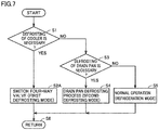
- Fig. 7 is a flowchart for illustrating control performed by a controller in Embodiment 2. The process of this flowchart is performed repeatedly every time a certain period of time elapses or a predetermined condition is satisfied during operation of the refrigeration apparatus.
- controller 210 determines whether defrosting of second heat exchanger 4 (cooler) is necessary. For example, when defrosting is performed per certain period of time, controller 210 makes a determination of step S1 in accordance with whether a certain period of time has elapsed from the last defrosting of the cooler. The determination of step S1 may be made based on a refrigerant temperature or a state of formation of frost on the cooler, which has been detected.
- refrigeration apparatus 200 When defrosting of second heat exchanger 4 (cooler) is necessary (YES at S1), refrigeration apparatus 200 is operated in the first defrosting mode. Specifically, controller 210 sets four-way valve 207 as shown in Fig. 6 at step S2A so as to circulate refrigerant in the backward direction indicated by the arrows of Fig. 6 . As a result, high-temperature gaseous refrigerant from compressor 1 flows into second heat exchanger 4, thus melting the frost which has formed on second heat exchanger 4.
- controller 210 determines whether defrosting of drain pan 5 is necessary at step S3.
- refrigeration apparatus 200 When defrosting of drain pan 5 is necessary (YES at S3), refrigeration apparatus 200 is operated in the second defrosting mode. In this case, controller 210 performs a process of defrosting drain pan 5 at step S4. In the second defrosting mode, refrigerant flows in the direction indicated by the arrows of Fig. 5 .
- the second defrosting mode is as described with reference to the flowchart of Fig. 4 , which will not be described repeatedly.
- controller 210 performs an operation in the refrigeration mode, which is a normal operation, at step S5.
- refrigerant flows in the direction indicated by the arrows of Fig. 5 .
- Embodiment 2 The second defrosting mode in which drain pan 5 alone is defrosted separately from second heat exchanger 4 (cooler) is provided in Embodiment 2 as in Embodiment 1, as described above.
- second heat exchanger 4 (cooler) is defrosted with the heat of high-temperature, high-pressure gaseous refrigerant by setting the direction of circulation of refrigerant to the backward direction with four-way valve 207.
- the direction of circulation of refrigerant is returned to the forward direction to reduce or stop the rotation of fan 7 or increase the operation frequency of compressor 1, thereby increasing the temperature of the refrigerant to drain pan 5.
- a COP (Coefficient Of Performance) of the refrigeration apparatus somewhat decreases, but drain pan 5 alone can be defrosted while cooling the inside of the refrigeration apparatus by second heat exchanger 4 (cooler), so that cooling of the inside of the refrigeration apparatus can be maintained even when it takes time for defrosting or drainage of drain pan 5.
Landscapes
- Engineering & Computer Science (AREA)
- Physics & Mathematics (AREA)
- Mechanical Engineering (AREA)
- Thermal Sciences (AREA)
- General Engineering & Computer Science (AREA)
- Defrosting Systems (AREA)
Abstract
Description
- The present disclosure invention relates to a refrigeration apparatus.
- In a refrigeration apparatus, a defrosting mode for melting frost which forms on an evaporator is provided. For example,
Japanese Patent Laying-Open No. 05-126440 - PTL 1:
Japanese Patent Laying-Open No. 05-126440 - In
Japanese Patent Laying-Open No. 05-126440 - The present disclosure has been made to solve the above problem, and has an object to provide a refrigeration apparatus capable of restarting cooling by an evaporator immediately while facilitating drainage from a drain pan.
- The present disclosure relates to a refrigeration apparatus. The refrigeration apparatus includes a refrigerant circuit in which refrigerant circulates in order of a compressor, a first heat exchanger, an expansion device, and a second heat exchanger, and a drain pan arranged below the second heat exchanger. The refrigeration apparatus has, as operation modes, a refrigeration mode in which cooling is performed using the second heat exchanger, a first defrosting mode in which the second heat exchanger is heated, and a second defrosting mode in which the drain pan is heated.
- The refrigeration apparatus of the present disclosure has the second defrosting mode in which the drain pan is heated. The second defrosting mode is different from the first defrosting mode in which the second heat exchanger is defrosted. Accordingly, the refrigeration apparatus can restart cooling by the second heat exchanger immediately while facilitating drainage from the drain pan.
-
-
Fig. 1 shows a configuration of a refrigeration apparatus according toEmbodiment 1. -
Fig. 2 shows a configuration of acontroller 10 that controls the refrigeration apparatus. -
Fig. 3 is a flowchart for illustrating control performed by the controller inEmbodiment 1. -
Fig. 4 is a flowchart for illustrating a process of defrosting a drain pan performed at step S4 ofFig. 3 in detail. -
Fig. 5 shows a configuration of a refrigeration apparatus according toEmbodiment 2. -
Fig. 6 shows a refrigerant flow in a first defrosting mode in the refrigeration apparatus ofEmbodiment 2. -
Fig. 7 is a flowchart for illustrating control performed by a controller inEmbodiment 2. - Embodiments of the present disclosure will be described below in detail with reference to the drawings. Although several embodiments will be described below, an appropriate combination of the configurations described in the respective embodiments has been intended at the time of application. The same or corresponding parts will be designated by the same reference numerals, and a description thereof will not be repeated.
-
Fig. 1 shows a configuration of a refrigeration apparatus according toEmbodiment 1. Referring toFig. 1 , arefrigeration apparatus 100 includes a refrigerant circuit in which refrigerant circulates in order of acompressor 1, afirst heat exchanger 2, anexpansion device 3, and asecond heat exchanger 4, and adrain pan 5 arranged belowsecond heat exchanger 4. In a normal operation (refrigeration mode) of the refrigeration apparatus,first heat exchanger 2 operates as a condenser, andsecond heat exchanger 4 operates as an evaporator (also referred to as a cooler).Expansion device 3 may be an electronic expansion valve with a variable degree of opening, which may be, for example, a temperature-based automatic expansion valve or a capillary tube with a fixed degree of opening. -
Refrigeration apparatus 100 further includes aheater 6 for defrosting, which heatssecond heat exchanger 4, afan 7, which sends air tofirst heat exchanger 2, and atemperature sensor 30, which detects a refrigerant temperature. -
Compressor 1,first heat exchanger 2,fan 7, and acontrol unit 11 are arranged in anoutdoor unit 101. Apipe 28, which is connected to an inlet ofcompressor 1, apipe 21, which connects a discharge port ofcompressor 1 with a refrigerant inlet offirst heat exchanger 2, and apipe 22, which is connected to a refrigerant outlet offirst heat exchanger 2, are further arranged inoutdoor unit 101. -
Expansion device 3,second heat exchanger 4,heater 6,drain pan 5, and acontrol unit 12 are arranged in anindoor unit 102. Apipe 24, which is connected to a refrigerant inlet ofexpansion device 3, apipe 25, which connects a refrigerant outlet ofexpansion device 3 with a refrigerant inlet ofsecond heat exchanger 4, and apipe 26, which is connected to a refrigerant outlet ofsecond heat exchanger 4, are further arranged inindoor unit 102. -
Outdoor unit 101 andindoor unit 102 are connected byextension pipes Extension pipe 23 connectspipe 22 withpipe 24.Extension pipe 27 connectspipe 26 withpipe 28. - In the case of a configuration in which a refrigeration apparatus is not separated into an outdoor unit and an indoor unit, no extension pipe may be provided, and in such a case, constituent elements shown in
Fig. 1 may be housed in one housing, as in a household refrigerator. - In the present embodiment,
control unit 11 andcontrol unit 12 cooperate with each other ascontroller 10 to controlcompressor 1,fan 7,expansion device 3, andheater 6. -
Fig. 2 shows a configuration ofcontroller 10 that controls the refrigeration apparatus. Referring toFig. 2 ,control unit 11 includes aprocessor 41, amemory 42, and acommunication interface 43.Communication interface 43 is a device for communications withcontrol unit 12.Processor 41 controls an operation frequency ofcompressor 1 and a rotation speed offan 7 in accordance with data stored inmemory 42 and information obtained fromcontrol unit 12 viacommunication interface 43. -
Control unit 12 includes acommunication interface 53, which transmits and receives a signal to and fromcontrol unit 11, aprocessor 51, and amemory 52. -
Memories Processor 51 controlsheater 6 andexpansion device 3. -
Controller 10 shown inFig. 2 is implemented byprocessors memory memory control unit 12 is provided in each of the indoor units. In such a case, processors of the plurality of control units cooperate with one another to perform overall control ofrefrigeration apparatus 100. - The refrigeration apparatus according to the present embodiment has, as operation modes, a refrigeration mode in which cooling is performed using
second heat exchanger 4, a first defrosting mode in whichsecond heat exchanger 4 is heated, and a second defrosting mode in whichdrain pan 5 is heated. In the second defrosting mode, frost ondrain pan 5 is melted, and besides, a block of ice or water which has fallen fromsecond heat exchanger 4 to drainpan 5 is heated to facilitate drainage. - Pipe 24 connecting
first heat exchanger 2 withexpansion device 3 is configured to perform heat exchange with drainpan 5. For example, a part ofpipe 24 which is routed is arranged inside or outside ofdrain pan 5 so as to be in contact with the bottom surface ofdrain pan 5 in such a manner as to allow heat conduction. - In the first defrosting mode,
controller 10 operatesheater 6. In order to facilitate defrosting, it is preferable in the first defrosting mode thatcompressor 1 be stopped to prevent evaporation of refrigerant insecond heat exchanger 4. In the first defrosting mode, thus, cooling of the inside of the refrigeration apparatus bysecond heat exchanger 4 is interrupted. - Contrastingly, in the second defrosting mode,
controller 10 causesheater 6 not to operate and sets a rotation speed offan 7 in the second defrosting mode to be lower than a rotation speed offan 7 in the refrigeration mode while operatingcompressor 1. Through such control, a heat radiation amount from the refrigerant infirst heat exchanger 2 decreases, and accordingly, the temperature of the refrigerant inpipe 24 which is subjected to heat exchange withdrain pan 5 exceeds the temperature of the refrigerant in the refrigeration mode. This facilitates defrosting indrain pan 5 more than in a normal refrigeration mode, while maintaining cooling inside the refrigeration apparatus bysecond heat exchanger 4 to some extent. -
Fig. 3 is a flowchart for illustrating control performed by a controller inEmbodiment 1. A process of this flowchart is performed repeatedly every time a certain period of time elapses or a predetermined condition is satisfied during operation of the refrigeration apparatus. Referring toFigs. 1 and3 ,controller 10 determines whether defrosting of second heat exchanger 4 (cooler) is necessary at step S1. For example, when defrosting is performed per certain period of time,controller 10 makes a determination of step S1 in accordance with whether a certain period of time has elapsed from the last defrosting of the cooler. The determination of step S1 may be made based on a refrigerant temperature or a state of formation of frost on the cooler, which has been detected. - When defrosting of second heat exchanger 4 (cooler) is necessary (YES at S1),
refrigeration apparatus 100 is operated in the first defrosting mode. Specifically,controller 10 turns onheater 6 to heatsecond heat exchanger 4 at step S2. This melts frost which has formed onsecond heat exchanger 4. - Contrastingly, when defrosting of second heat exchanger 4 (cooler) is not necessary (NO at S1),
controller 10 determines whether defrosting ofdrain pan 5 is necessary at step S3. - When defrosting of
drain pan 5 is necessary (YES at S3),refrigeration apparatus 100 is operated in the second defrosting mode. In this case,controller 10 performs a process of defrostingdrain pan 5 at step S4. Contrastingly, when defrosting ofdrain pan 5 is not necessary (NO at S3),controller 10 performs an operation in the refrigeration mode, which is a normal operation, at step S5. -
Fig. 4 is a flowchart for illustrating a process of defrosting a drain pan performed at step S4 ofFig. 3 in detail. When the process of defrosting a drain pan is started, at step S11,controller 10 determines whether a refrigerant temperature T of refrigerant which passes throughpipe 24, detected bytemperature sensor 30, is lower than a determination value. - When refrigerant temperature T is lower than the determination value (YES at S11), refrigerant temperature T needs to be increased for defrosting in
drain pan 5.Controller 10 accordingly reduces the rotation offan 7 of the outdoor unit at step S12. As a result, a pressure of a high-pressure portion of the refrigerant increases, and refrigerant temperature T increases. Note that at step S12, the operation frequency ofcompressor 1 may be increased in place of reducing the rotation offan 7. - When refrigerant temperature T is not less than the determination value (NO at S11), the refrigerant temperature has reached a temperature suitable for defrosting, and accordingly, circulation of the refrigerant is continued in this state. Subsequently,
controller 10 determines whether defrosting ofdrain pan 5 is complete at step S13. When defrosting is not complete (NO at S13), the process returns again to step S11, and defrosting is continued. Contrastingly, when defrosting is complete (YES at S13), the process moves to the flowchart ofFig. 3 at step S14. - As described above, the second defrosting mode in which
drain pan 5 alone is defrosted separately from second heat exchanger 4 (cooler) is provided inEmbodiment 1. - Specifically, in the first defrosting mode, second heat exchanger 4 (cooler) is defrosted with the heat from
heater 6. In the second defrosting mode, heating byheater 6 is stopped to reduce or stop the rotation offan 7 or increase the operation frequency ofcompressor 1, thereby increasing the temperature of the refrigerant to drainpan 5. - Thus, a COP (Coefficient Of Performance) of the refrigeration apparatus somewhat decreases, but
drain pan 5 alone can be defrosted while cooling the inside of the refrigeration apparatus by second heat exchanger 4 (cooler), so that the inside of the refrigeration apparatus can be maintained even when it takes time for defrosting or drainage ofdrain pan 5. - In
Embodiment 1,heater 6 is used for defrosting ofsecond heat exchanger 4 in the first defrosting mode. Contrastingly, inEmbodiment 2, high-temperature, high-pressure gaseous refrigerant which is discharged fromcompressor 1 is introduced intosecond heat exchanger 4 in the first defrosting mode. -
Fig. 5 shows a configuration of a refrigeration apparatus according toEmbodiment 2. Referring toFig. 5 , arefrigeration apparatus 200 includes a refrigerant circuit in which refrigerant circulates in order ofcompressor 1,first heat exchanger 2,expansion device 3, andsecond heat exchanger 4, anddrain pan 5 arranged belowsecond heat exchanger 4. In a normal operation (refrigeration mode) of the refrigeration apparatus,first heat exchanger 2 operates as a condenser, andsecond heat exchanger 4 operates as an evaporator (also referred to as a cooler).Expansion device 3 may be an electronic expansion valve with a variable degree of opening, which may be, for example, a temperature-based automatic expansion valve or a capillary tube with a fixed degree of opening. -
Refrigeration apparatus 200 further includes a four-way valve 207, which changes a direction of circulation of refrigerant,fan 7 that sends air tofirst heat exchanger 2, andtemperature sensor 30 that detects a refrigerant temperature. -
Compressor 1,first heat exchanger 2,fan 7, and acontrol unit 211 are arranged in anoutdoor unit 201. Apipe 228, which connects four-way valve 207 withextension pipe 27, apipe 229, which connects four-way valve 207 with the inlet ofcompressor 1, apipe 221, which connects the discharge port ofcompressor 1 with four-way valve 207, apipe 222, which connects four-way valve 207 with the refrigerant inlet offirst heat exchanger 2, andpipe 22 connected to the refrigerant outlet offirst heat exchanger 2 are further arranged inoutdoor unit 101. -
Expansion device 3,second heat exchanger 4,drain pan 5, and acontrol unit 212 are arranged in anindoor unit 202.Pipe 24 connected to the refrigerant inlet ofexpansion device 3,pipe 25 connecting the refrigerant outlet ofexpansion device 3 with the refrigerant inlet ofsecond heat exchanger 4, andpipe 26 connected to the refrigerant outlet ofsecond heat exchanger 4 are further arranged inindoor unit 202. -
Outdoor unit 201 andindoor unit 202 are connected byextension pipes Extension pipe 23 connectspipe 22 withpipe 24.Extension pipe 27 connectspipe 26 withpipe 228. - In the case of a configuration in which a refrigeration apparatus is not separated into an outdoor unit and an indoor unit, no extension pipe may be provided, and in such a case, the constituent elements shown in
Fig. 5 may be housed in one housing as in a household refrigerator. - In the present embodiment,
control unit 211 andcontrol unit 212 cooperate with each other ascontroller 210 to controlcompressor 1,fan 7,expansion device 3, and four-way valve 207.Control unit 211,control unit 212, andcontroller 210 have configurations similar to those ofcontrol unit 11,control unit 12, andcontroller 10 shown inFig. 2 . - In the refrigeration mode and the second defrosting mode, four-
way valve 207 is set to causepipe 221 andpipe 222 to communicate with each other andpipe 228 andpipe 229 to communicate with each other as indicated by the solid line ofFig. 5 . As a result, refrigerant circulates in the direction indicated by the arrows ofFig. 5 in the refrigeration mode and the second defrosting mode. -
Fig. 6 shows a refrigerant flow in the first defrosting mode in the refrigeration apparatus ofEmbodiment 2. Referring toFig. 6 , in the first defrosting mode, four-way valve 207 is set to causepipe 221 andpipe 228 to communicate with each other andpipe 222 andpipe 229 to communicate with each other as indicated by the solid line ofFig. 6 . As a result, refrigerant circulates in the direction indicated by the arrows ofFig. 6 in the first defrosting mode. - Specifically, four-
way valve 207 is configured to, in the first defrosting mode, change the direction of circulation of refrigerant in the refrigerant circuit to a backward direction in which refrigerant circulates in order ofcompressor 1,second heat exchanger 4,expansion device 3, andfirst heat exchanger 2, which is opposite to a forward direction. - In the refrigeration apparatus of
Embodiment 2, four-way valve 207 is set such that the direction of circulation of refrigerant is the forward direction in the refrigeration mode. In this case,first heat exchanger 2 operates as a condenser, andsecond heat exchanger 4 operates as an evaporator. - In contrast, four-
way valve 207 is set such that the direction of circulation of refrigerant is the backward direction in the first defrosting mode. In this case, sincefirst heat exchanger 2 operates as an evaporator andsecond heat exchanger 4 operates as a condenser, cooling of the inside of the refrigeration apparatus cannot be continued and is interrupted. - In contrast, four-
way valve 207 is set such that the direction of circulation of refrigerant is the forward direction in the second defrosting mode.Pipe 24 connected betweenfirst heat exchanger 2 andexpansion device 3 is configured to perform heat exchange withdrain pan 5 also inrefrigeration apparatus 200 ofEmbodiment 2 as inrefrigeration apparatus 100 ofEmbodiment 1. - The rotation speed of
fan 7 in the second defrosting mode is set to be lower than the rotation speed offan 7 in the refrigeration mode. This increases the temperature of refrigerant flowing throughpipe 24, thus facilitating heating ofdrain pan 5. -
Fig. 7 is a flowchart for illustrating control performed by a controller inEmbodiment 2. The process of this flowchart is performed repeatedly every time a certain period of time elapses or a predetermined condition is satisfied during operation of the refrigeration apparatus. Referring toFigs. 5 and7 , at step S1,controller 210 determines whether defrosting of second heat exchanger 4 (cooler) is necessary. For example, when defrosting is performed per certain period of time,controller 210 makes a determination of step S1 in accordance with whether a certain period of time has elapsed from the last defrosting of the cooler. The determination of step S1 may be made based on a refrigerant temperature or a state of formation of frost on the cooler, which has been detected. - When defrosting of second heat exchanger 4 (cooler) is necessary (YES at S1),
refrigeration apparatus 200 is operated in the first defrosting mode. Specifically,controller 210 sets four-way valve 207 as shown inFig. 6 at step S2A so as to circulate refrigerant in the backward direction indicated by the arrows ofFig. 6 . As a result, high-temperature gaseous refrigerant fromcompressor 1 flows intosecond heat exchanger 4, thus melting the frost which has formed onsecond heat exchanger 4. - Contrastingly, when defrosting of second heat exchanger 4 (cooler) is not necessary (NO at S1),
controller 210 determines whether defrosting ofdrain pan 5 is necessary at step S3. - When defrosting of
drain pan 5 is necessary (YES at S3),refrigeration apparatus 200 is operated in the second defrosting mode. In this case,controller 210 performs a process of defrostingdrain pan 5 at step S4. In the second defrosting mode, refrigerant flows in the direction indicated by the arrows ofFig. 5 . The second defrosting mode is as described with reference to the flowchart ofFig. 4 , which will not be described repeatedly. - Contrastingly, when defrosting of
drain pan 5 is not necessary (NO at S3),controller 210 performs an operation in the refrigeration mode, which is a normal operation, at step S5. In the refrigeration mode, refrigerant flows in the direction indicated by the arrows ofFig. 5 . - The second defrosting mode in which
drain pan 5 alone is defrosted separately from second heat exchanger 4 (cooler) is provided inEmbodiment 2 as inEmbodiment 1, as described above. - Specifically, in the first defrosting mode, second heat exchanger 4 (cooler) is defrosted with the heat of high-temperature, high-pressure gaseous refrigerant by setting the direction of circulation of refrigerant to the backward direction with four-
way valve 207. In the second defrosting mode, the direction of circulation of refrigerant is returned to the forward direction to reduce or stop the rotation offan 7 or increase the operation frequency ofcompressor 1, thereby increasing the temperature of the refrigerant to drainpan 5. - Thus, a COP (Coefficient Of Performance) of the refrigeration apparatus somewhat decreases, but
drain pan 5 alone can be defrosted while cooling the inside of the refrigeration apparatus by second heat exchanger 4 (cooler), so that cooling of the inside of the refrigeration apparatus can be maintained even when it takes time for defrosting or drainage ofdrain pan 5. - The embodiments disclosed herein have been presented for the purpose of illustration and non-restrictive in every respect. It is therefore intended that the scope of the present disclosure is defined by claims, not only by the embodiments described above, and encompasses all modifications and variations equivalent in meaning and scope to the claims.
- 1 compressor; 2 first heat exchanger; 3 expansion device; 4 second heat exchanger; 5 drain pan; 6 heater; 7 fan; 10, 210 controller; 11, 12, 211, 212 control unit; 21, 22, 24, 25, 26, 28, 221, 222, 228, 229 pipe; 23, 27 extension pipe; 30 temperature sensor; 41, 51 processor; 42, 52 memory; 43, 53 communication interface; 100, 200 refrigeration apparatus; 101, 201 outdoor unit; 102, 202 indoor unit; 207 four-way valve.
Claims (3)
- A refrigeration apparatus comprising:a refrigerant circuit in which refrigerant circulates in order of a compressor, a first heat exchanger, an expansion device, and a second heat exchanger; anda drain pan arranged below the second heat exchanger, whereinthe refrigeration apparatus has, as operation modes, a refrigeration mode in which cooling is performed using the second heat exchanger, a first defrosting mode in which the second heat exchanger is heated, and a second defrosting mode in which the drain pan is heated.
- The refrigeration apparatus according to claim 1, further comprising:a heater configured to heat the second heat exchanger;a fan configured to send air to the first heat exchanger; anda refrigerant pipe connected between the first heat exchanger and the expansion device, the refrigerant pipe being configured to perform heat exchange with the drain pan, whereinthe heater operates in the first defrosting mode,the heater does not operate in the second defrosting mode, anda rotation speed of the fan in the second defrosting mode is set to be lower than a rotation speed of the fan in the refrigeration mode.
- The refrigeration apparatus according to claim 1, further comprising:a four-way valve configured to change a direction of circulation of the refrigerant in the refrigerant circuit between a forward direction and a backward direction, the backward direction being opposite to the forward direction, the refrigerant circulating in order of the compressor, the second heat exchanger, the expansion device, and the first heat exchanger in the backward direction;a fan configured to send air to the first heat exchanger; anda refrigerant pipe connected between the first heat exchanger and the expansion device, the refrigerant pipe being configured to perform heat exchange with the drain pan, whereinin the refrigeration mode, the four-way valve is set such that the direction of circulation is the forward direction,in the first defrosting mode, the four-way valve is set such that the direction of circulation is the backward direction,in the second defrosting mode, the four-way valve is set such that the direction of circulation is the forward direction, anda rotation speed of the fan in the second defrosting mode is set to be lower than a rotation speed of the fan in the refrigeration mode.
Applications Claiming Priority (1)
| Application Number | Priority Date | Filing Date | Title |
|---|---|---|---|
| PCT/JP2019/004078 WO2020161804A1 (en) | 2019-02-05 | 2019-02-05 | Freezing device |
Publications (2)
| Publication Number | Publication Date |
|---|---|
| EP3922927A1 true EP3922927A1 (en) | 2021-12-15 |
| EP3922927A4 EP3922927A4 (en) | 2022-01-19 |
Family
ID=71948169
Family Applications (1)
| Application Number | Title | Priority Date | Filing Date |
|---|---|---|---|
| EP19914342.1A Withdrawn EP3922927A4 (en) | 2019-02-05 | 2019-02-05 | Freezing device |
Country Status (4)
| Country | Link |
|---|---|
| EP (1) | EP3922927A4 (en) |
| JP (1) | JPWO2020161804A1 (en) |
| CN (1) | CN113366273A (en) |
| WO (1) | WO2020161804A1 (en) |
Family Cites Families (11)
| Publication number | Priority date | Publication date | Assignee | Title |
|---|---|---|---|---|
| JPS5869364A (en) * | 1981-10-20 | 1983-04-25 | 三菱電機株式会社 | Refrigerator |
| JP2831838B2 (en) * | 1990-11-06 | 1998-12-02 | 株式会社東芝 | Air conditioner |
| JPH05126440A (en) * | 1991-11-05 | 1993-05-21 | Sanyo Electric Co Ltd | Freezer |
| JP2009144951A (en) * | 2007-12-13 | 2009-07-02 | Fuji Koki Corp | Defrosting operation control device for refrigerating-freezing device and its method |
| JP5197244B2 (en) * | 2008-09-02 | 2013-05-15 | 三菱電機株式会社 | Refrigeration cycle apparatus, refrigeration apparatus and air conditioner |
| JP2013036650A (en) * | 2011-08-05 | 2013-02-21 | Daikin Industries Ltd | Refrigerator |
| JP5604543B2 (en) * | 2013-02-28 | 2014-10-08 | 日立アプライアンス株式会社 | refrigerator |
| CN203869168U (en) * | 2014-05-13 | 2014-10-08 | 广东美的制冷设备有限公司 | Air conditioner and indoor unit thereof |
| JP6137262B2 (en) * | 2015-09-30 | 2017-05-31 | ダイキン工業株式会社 | Refrigeration equipment |
| JP6602476B2 (en) * | 2016-07-11 | 2019-11-06 | 三菱電機株式会社 | Refrigeration equipment |
| CN106288532B (en) * | 2016-10-13 | 2018-06-29 | 珠海格力电器股份有限公司 | Heat exchanger assembly, air cooler, refrigerating unit and control method thereof |
-
2019
- 2019-02-05 JP JP2020570247A patent/JPWO2020161804A1/en active Pending
- 2019-02-05 EP EP19914342.1A patent/EP3922927A4/en not_active Withdrawn
- 2019-02-05 WO PCT/JP2019/004078 patent/WO2020161804A1/en not_active Ceased
- 2019-02-05 CN CN201980090546.1A patent/CN113366273A/en active Pending
Also Published As
| Publication number | Publication date |
|---|---|
| JPWO2020161804A1 (en) | 2021-12-02 |
| CN113366273A (en) | 2021-09-07 |
| EP3922927A4 (en) | 2022-01-19 |
| WO2020161804A1 (en) | 2020-08-13 |
Similar Documents
| Publication | Publication Date | Title |
|---|---|---|
| JP5641875B2 (en) | Refrigeration equipment | |
| EP4033177B1 (en) | Air conditioner | |
| JP2002107014A (en) | Air conditioner | |
| EP3267130B1 (en) | Refrigeration cycle device | |
| JP5178771B2 (en) | Freezer refrigerator | |
| US11320186B2 (en) | Heat pump with defrost termination based upon system temperatures | |
| US11802702B2 (en) | Controller of air conditioning apparatus, outdoor unit, relay unit, heat source unit, and air conditioning apparatus | |
| JP6591074B2 (en) | Air conditioner | |
| US6609390B1 (en) | Two-refrigerant refrigerating device | |
| JP2015064169A (en) | Hot water generator | |
| WO2010070932A1 (en) | Refrigeration equipment | |
| JP5558132B2 (en) | Refrigerator and refrigeration apparatus to which the refrigerator is connected | |
| JP7034227B1 (en) | Air conditioner and management device | |
| WO2018229826A1 (en) | Refrigeration cycle device | |
| US20210341193A1 (en) | Air Conditioning Device | |
| JP4269476B2 (en) | Refrigeration equipment | |
| EP3922927A1 (en) | Freezing device | |
| JP6529579B2 (en) | Heat pump system | |
| JP2001272144A (en) | Air conditioner | |
| JP2021162250A (en) | Heat pump cycle device | |
| JP2018087675A (en) | Refrigeration equipment | |
| JP7459907B2 (en) | Dual refrigeration cycle device and control method for dual refrigeration cycle device | |
| JP2007247997A (en) | Air conditioner | |
| JPH11211186A (en) | Air conditioner defrost control device | |
| WO2020049660A1 (en) | Refrigeration cycle device |
Legal Events
| Date | Code | Title | Description |
|---|---|---|---|
| STAA | Information on the status of an ep patent application or granted ep patent |
Free format text: STATUS: THE INTERNATIONAL PUBLICATION HAS BEEN MADE |
|
| PUAI | Public reference made under article 153(3) epc to a published international application that has entered the european phase |
Free format text: ORIGINAL CODE: 0009012 |
|
| STAA | Information on the status of an ep patent application or granted ep patent |
Free format text: STATUS: REQUEST FOR EXAMINATION WAS MADE |
|
| 17P | Request for examination filed |
Effective date: 20210729 |
|
| AK | Designated contracting states |
Kind code of ref document: A1 Designated state(s): AL AT BE BG CH CY CZ DE DK EE ES FI FR GB GR HR HU IE IS IT LI LT LU LV MC MK MT NL NO PL PT RO RS SE SI SK SM TR |
|
| A4 | Supplementary search report drawn up and despatched |
Effective date: 20211222 |
|
| RIC1 | Information provided on ipc code assigned before grant |
Ipc: F25B 49/02 20060101ALI20211216BHEP Ipc: F25B 40/02 20060101ALI20211216BHEP Ipc: F25B 6/04 20060101ALI20211216BHEP Ipc: F25B 47/02 20060101AFI20211216BHEP |
|
| DAV | Request for validation of the european patent (deleted) | ||
| DAX | Request for extension of the european patent (deleted) | ||
| GRAP | Despatch of communication of intention to grant a patent |
Free format text: ORIGINAL CODE: EPIDOSNIGR1 |
|
| STAA | Information on the status of an ep patent application or granted ep patent |
Free format text: STATUS: GRANT OF PATENT IS INTENDED |
|
| INTG | Intention to grant announced |
Effective date: 20240708 |
|
| STAA | Information on the status of an ep patent application or granted ep patent |
Free format text: STATUS: THE APPLICATION IS DEEMED TO BE WITHDRAWN |
|
| 18D | Application deemed to be withdrawn |
Effective date: 20241109 |