EP3922865A1 - Pipe protection device and cooling device - Google Patents
Pipe protection device and cooling device Download PDFInfo
- Publication number
- EP3922865A1 EP3922865A1 EP20752168.3A EP20752168A EP3922865A1 EP 3922865 A1 EP3922865 A1 EP 3922865A1 EP 20752168 A EP20752168 A EP 20752168A EP 3922865 A1 EP3922865 A1 EP 3922865A1
- Authority
- EP
- European Patent Office
- Prior art keywords
- supply
- discharge
- side support
- pipe
- support part
- Prior art date
- Legal status (The legal status is an assumption and is not a legal conclusion. Google has not performed a legal analysis and makes no representation as to the accuracy of the status listed.)
- Granted
Links
Images




Classifications
-
- G—PHYSICS
- G06—COMPUTING OR CALCULATING; COUNTING
- G06F—ELECTRIC DIGITAL DATA PROCESSING
- G06F1/00—Details not covered by groups G06F3/00 - G06F13/00 and G06F21/00
- G06F1/16—Constructional details or arrangements
- G06F1/18—Packaging or power distribution
- G06F1/181—Enclosures
- G06F1/182—Enclosures with special features, e.g. for use in industrial environments; grounding or shielding against radio frequency interference [RFI] or electromagnetical interference [EMI]
-
- H—ELECTRICITY
- H05—ELECTRIC TECHNIQUES NOT OTHERWISE PROVIDED FOR
- H05K—PRINTED CIRCUITS; CASINGS OR CONSTRUCTIONAL DETAILS OF ELECTRIC APPARATUS; MANUFACTURE OF ASSEMBLAGES OF ELECTRICAL COMPONENTS
- H05K7/00—Constructional details common to different types of electric apparatus
- H05K7/20—Modifications to facilitate cooling, ventilating, or heating
- H05K7/20218—Modifications to facilitate cooling, ventilating, or heating using a liquid coolant without phase change in electronic enclosures
- H05K7/20272—Accessories for moving fluid, for expanding fluid, for connecting fluid conduits, for distributing fluid, for removing gas or for preventing leakage, e.g. pumps, tanks or manifolds
-
- F—MECHANICAL ENGINEERING; LIGHTING; HEATING; WEAPONS; BLASTING
- F28—HEAT EXCHANGE IN GENERAL
- F28F—DETAILS OF HEAT-EXCHANGE AND HEAT-TRANSFER APPARATUS, OF GENERAL APPLICATION
- F28F9/00—Casings; Header boxes; Auxiliary supports for elements; Auxiliary members within casings
- F28F9/02—Header boxes; End plates
- F28F9/0246—Arrangements for connecting header boxes with flow lines
-
- F—MECHANICAL ENGINEERING; LIGHTING; HEATING; WEAPONS; BLASTING
- F28—HEAT EXCHANGE IN GENERAL
- F28F—DETAILS OF HEAT-EXCHANGE AND HEAT-TRANSFER APPARATUS, OF GENERAL APPLICATION
- F28F9/00—Casings; Header boxes; Auxiliary supports for elements; Auxiliary members within casings
- F28F9/26—Arrangements for connecting different sections of heat-exchange elements, e.g. of radiators
-
- G—PHYSICS
- G06—COMPUTING OR CALCULATING; COUNTING
- G06F—ELECTRIC DIGITAL DATA PROCESSING
- G06F1/00—Details not covered by groups G06F3/00 - G06F13/00 and G06F21/00
- G06F1/16—Constructional details or arrangements
- G06F1/20—Cooling means
-
- H—ELECTRICITY
- H05—ELECTRIC TECHNIQUES NOT OTHERWISE PROVIDED FOR
- H05K—PRINTED CIRCUITS; CASINGS OR CONSTRUCTIONAL DETAILS OF ELECTRIC APPARATUS; MANUFACTURE OF ASSEMBLAGES OF ELECTRICAL COMPONENTS
- H05K7/00—Constructional details common to different types of electric apparatus
- H05K7/20—Modifications to facilitate cooling, ventilating, or heating
- H05K7/20709—Modifications to facilitate cooling, ventilating, or heating for server racks or cabinets; for data centers, e.g. 19-inch computer racks
- H05K7/20763—Liquid cooling without phase change
- H05K7/20772—Liquid cooling without phase change within server blades for removing heat from heat source
-
- G—PHYSICS
- G06—COMPUTING OR CALCULATING; COUNTING
- G06F—ELECTRIC DIGITAL DATA PROCESSING
- G06F2200/00—Indexing scheme relating to G06F1/04 - G06F1/32
- G06F2200/20—Indexing scheme relating to G06F1/20
- G06F2200/201—Cooling arrangements using cooling fluid
Definitions
- the present invention relates to a pipe protection device and a cooling device
- a cooling method in which electronic devices accommodated in a server rack are cooled by a heat exchange medium such as water.
- a hose for supplying and discharging cooling water to a cooling unit is used on a back surface thereof.
- a cooling unit in which a supply pipe and a discharge pipe are connected to a tank-shaped component which is in contact with a heat generating part or the like is used.
- a method in which a plurality of servers is accommodated in a rack in a multi-stage manner is adopted.
- An example of object of the present invention is to prevent entanglement of a supply pipe and a discharge pipe of a cooling unit used for cooling an electronic device, excessive pulling-out thereof, or damage to a coupler thereof.
- a pipe protection device is a pipe protection device which is provided at a supply-side coupler provided at an end portion of a supply pipe which supplies a heat exchange medium to a heat exchange unit, and a discharge-side coupler provided at an end portion of a discharge pipe from which the heat exchange medium, which is supplied from the supply pipe to the heat exchange unit, is discharged, including a supply-side support part having a recess along a contour of part of the supply pipe, a discharge-side support part having a recess along a contour of part of the discharge pipe, and a connecting part which supports the supply-side support part and the discharge-side support part at a predetermined interval and connects the supply-side support part and the discharge-side support part to a housing constituting a server.
- the reference numeral 1 represents couplers, and one of upper and lower couplers 1 is provided at a tip end of a supply pipe and is connected to a collecting pipe (not shown) on the supply side of a heat medium, for example, as part of the supply pipe which supplies the heat medium to a tank-shaped cooling unit (not shown) having a predetermined volume.
- the other one of the two couplers 1 is connected to a collecting pipe (not shown) on the recovery side of the heat medium provided at a tip end of a discharge pipe, for example, as part of the discharge pipe which discharges the heat medium in which heat is exchanged by the cooling unit.
- One of the couplers 1 is supported by a supply-side support part 3 having a recess 2 along the contour of the coupler 1, and the other one of the couplers 1 is also supported by a discharge-side support part 4 having a recess 2 along the contour of the coupler 1.
- the supply-side support part 3 and the discharge-side support part 4 are integrally formed to support the two couplers 1 in a predetermined positional relationship.
- an upper part is referred to as the supply-side support part 3 and the lower part is referred to as the discharge-side support part 4.
- supply-side support part 3 and the discharge-side support part 4 are mounted in a housing (not shown) of an electronic device such as a server by a connecting part 5 integrally provided therein.
- the two couplers 1 can be accommodated in the supply-side support part 3 and the discharge-side support part 4 in a state in which they are fitted in the recesses 2 and can be fixed in a constant positional relationship. Further, because they are connected to the housing in a state in which they are supported by the supply-side support part 3 and the discharge-side support part 4, a position of a pipe having the coupler 1 can be stabilized. Therefore, for example, when the housing is inserted into or removed from a rack, the coupler or the pipe located at the back side of the housing is prevented from being caught in the rack or the housing or being crushed and damaged.
- the respective couplers 1 are generally mounted on a piping material such as a hose. Therefore, the recesses 2 of the supply-side support part 3 and the discharge-side support part 4 include one which accommodates not only the coupler 1 but also part of the piping material mounted thereon.
- FIG. 2 is a perspective view showing a server equipped with the protection device according to the first embodiment.
- the reference numeral 10 represents a server (for convenience, an exterior of the housing which accommodates the server is shown), and an electronic device such as a circuit board is accommodated in the server 10. Further, a cooling unit (not shown) which accommodates a heat medium for absorbing heat is provided in a heat generating component mounted in the electronic device, for example, a semiconductor device.
- the reference numeral 20 in FIG. 2 represents a supply pipe for supplying the heat medium to the cooling unit, and the supply pipe 20 is formed of, for example, rubber and is flexibly formed.
- the reference numeral 30 represents a discharge pipe for discharging the heat medium from the cooling unit, and the discharge pipe 30 is formed of, for example, rubber, like the supply pipe 20, and is flexibly formed.
- the supply pipe 20 and the discharge pipe 30 are pulled out from an opening part 11 on a back surface of the server 10, as shown in FIG. 2 .
- four cooling units are built in the server 10, and the supply pipe 20 and the discharge pipe 30 are connected in parallel to each of the cooling units.
- the couplers 1 are mounted on the respective tip ends of each of the supply pipe 20 and the discharge pipe 30 to detachably connect the tip ends to other pipes such as a supply-side collecting pipe (not shown) which is a supply source of the heat medium and a recovery-side collecting pipe (not shown) which is a recovery source.
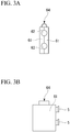
- FIGS. 3A and 3B are a front view and a side view of the protection device of the first embodiment.
- the protection device which accommodates and protects the supply pipe 20, the discharge pipe 30, and the coupler 1, has an exterior as shown in the front view of FIG. 3A or the side view of FIG. 3B as a whole.
- the protection device has two cap pieces 61 which are combined in a state in which they face each other, and each of the cap pieces 61 has a recess 62 as a supply-side support part and a recess 63 as a discharge-side support part. Further, the two cap pieces 61 are connected to each other by an elastically deformable connecting plate 64.
- FIGS. 4A to 4C are side views of an open state, a set state, and a closed state of the protection device of the first embodiment. More specifically, as shown in FIG. 4A , two cap pieces 61 are disposed line-symmetrically, and a configuration in which the two cap pieces 61 are connected by the thin plate-shaped connecting plate 64 is adopted.
- FIG. 4A shows a state in which joining surfaces of the two cap pieces 61 are developed to be arranged on the same plane, and the connecting plate 64 extends in a plane shape between the two cap pieces 61. Further, the connecting plate 64 has a streak shape in a left and right direction of FIG. 4A , and irregularities are repeatedly formed in a vertical direction of the drawing. Therefore, the connecting plate 64 is molded so that bending deformation is easily achieved when the cap pieces 61 face each other.
- the recess 62 has a hose accommodating part 62a in which a hose is accommodated as a supply pipe, and a coupler accommodating part 62b in which the coupler 1 at the tip end of the hose is accommodated.
- the recess 63 has a hose accommodating part 63a in which a hose is accommodated as a discharge pipe and a coupler accommodating part 63b in which the coupler 1 at the tip end of the hose is accommodated.
- a clearance (a gap) between the recesses 62 and 63, the supply pipe 20, the discharge pipe 30, and an exterior (a contour) of the coupler 1 is set to be larger, operability when mounting and removal is improved.
- the clearance (the gap) is set smaller, the cap piece 61 can be held stably without rattling when the cap pieces 61 are integrally held.
- the two cap pieces 61 in which the recesses 62 and 63 are formed and the connecting plate 64 which connects the two cap pieces 61 can be manufactured, for example, by integrally molding soft plastic, rubber, or a mixture thereof.
- FIG. 5 is a side view showing a state in which the protection device of the first embodiment is mounted on the rack.
- FIG. 6 is a perspective view of the server equipped with the protection device of the first embodiment when seen from the rear surface side.
- the cap pieces 61 and 61 of the protection device are prepared in an unfolded state.
- the two recesses 62 and 63 are positioned parallel to each other.
- the supply pipe 20, the discharge pipe 30, and the couplers 1 at the tip ends of the supply pipe 20 and the discharge pipe 30 are fitted and accommodated in the recesses 62 and 63 of one of the cap pieces 61 (on the lower side in the shown example).
- the supply pipe 20, the discharge pipe 30, and lower half portions of the couplers 1 are accommodated in the recesses 62 and 63 of one of the cap pieces 61 (on the lower side in the shown example).
- the supply pipe 20 is accommodated in the hose accommodating part 62a
- the coupler 1 is accommodated in the coupler accommodating part 62b.
- the discharge pipe 30 is accommodated in the hose accommodating part 63a
- the coupler 1 is accommodated in the coupler accommodating part 63b.
- the upper cap piece 61 overlaps the lower cap piece 61 while the connecting plate 64 is bent. Then, as shown in FIG. 4C , the recesses 62 and 63 of the upper cap piece 61 and the recesses 62 and 63 of the lower cap piece 61 overlap each other in a state in which they face each other. As a result, the recesses 62 and 63 become an integral space, and the supply pipe 20, the discharge pipe 30, and the couplers 1 at the tip end thereof are accommodated in this space.
- the two cap pieces 61 can be kept closed by engaging the connecting parts 5 with each other in this state, or by wrapping a rubber belt or the like therearound and also using a fixing means such as bolt tightening.
- the supply pipe 20, the discharge pipe 30, and the couplers 1 at the tip ends thereof are accommodated between the two cap pieces 61 and 61. Therefore, the whole of the protection device is protected, and it is less likely to be damaged by interference with peripheral devices in a region in which wires and devices are crowded, such as the back surface side of the server. Further, as shown in FIGS. 5 and 6 , the hoses constituting the supply pipe 20 and the discharge pipe 30 can be disposed at predetermined positions in an orderly manner by hooking the connecting part 5 on part of the housing 10.
- the supply pipe 20 and the discharge pipe 30 are put in and out of the rack in a state in which they are collectively supported by a rear portion of the housing 10 using the protection device of the first embodiment. Then, after the mounting or removal (insertion or withdrawal) of the housing 10 is completed, the cap piece 61 is opened, and the supply pipe 20, the discharge pipe 30, and the couplers 1 are taken out from the recesses 62 and 63 and are connected to predetermined pipes to supply or recover the heat medium.
- the electronic components and the like in the server 10 can be cooled.
- FIGS. 7 to 9 show a second embodiment.
- the same components as those in FIGS. 1 to 6 are designated by the same reference numerals, and the description thereof is simplified.
- FIG. 7 is a perspective view of the protection device according to the second embodiment.
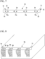
- FIG. 8 is a perspective view of the server equipped with the protection device of the second embodiment when seen from the rear surface side.
- the reference numeral 70 in FIGS. 7 to 9 represents a connecting part mounted on the back surface of the server 10 as shown in FIG. 8 .
- the connecting part 70 has a plate shape as a whole and has protrusions 71 which protrude in forward and rearward directions (in a depth direction of the server 10) at both ends on the upper side (the upper surface side of the server 10), for example, by bending part of a sheet metal.
- a leaf spring 72 having a structure in which a thin plate-shaped spring steel is formed in a curved shape is provided on a lower surface of each of the protrusions 71.
- the leaf spring 72 is mounted on the lower surface of the protrusion 71 so that it can be elastically deformed in a thickness direction of the protrusion 71.
- claw parts 73 which protrude in the forward and rearward directions (in the depth direction of the server 10) are formed at both ends of the connecting part 70 on the lower side (the lower surface side of the server 10), for example, by bending part of the sheet metal.
- the claw part 73 is formed to be hooked on part of the housing constituting the server 10.
- the connecting part 70 is mounted on the back surface of the server 10 by elastically deforming the leaf spring 72 in a state in which the claw part 73 is hooked.
- FIG. 9 is a longitudinal cross-sectional view of the protection device of the second embodiment.
- a through hole 70a is formed in the connecting part 70, and a grommet 74 formed of an elastic body such as rubber is mounted in the through hole 70a.
- the grommet 74 is removably mounted in the support part 70 by sandwiching the sheet metal around the through hole 70a therebetween with flange parts 74a. Further, the grommet 74 fixes the supply pipe 20 or the discharge pipe 30 to the connecting part 70 by being elastically deformed around the hose constituting the supply pipe 20 or the discharge pipe 30.
- the connecting part 70 also has a function of connecting the supply pipe 20 and the discharge pipe 30, or the couplers (not shown in FIGS. 7 to 9 ) integrated with the supply pipe 20 and the discharge pipe 30 to the housing 10 while a predetermined arrangement relationship is maintained.
- the supply pipe 20 and the discharge pipe 30 are supported by the connecting part 70.
- the hoses constituting the supply pipe 20 or the discharge pipe 30 can be mounted in an orderly manner at predetermined positions on the back surface of the server 10.
- the length, the diameter and the number of the supply pipes and discharge pipes, and the diameter, the structure, and the number of the couplers may be appropriately changed according to specifications of the pipe material and accessories used in the piping system in which the heat medium circulates.
- the present invention can be used for electronic devices such as servers and the like which require supply and discharge of a cooling medium to a cooling unit that cools heat-generating components.
Landscapes
- Engineering & Computer Science (AREA)
- Physics & Mathematics (AREA)
- Thermal Sciences (AREA)
- Microelectronics & Electronic Packaging (AREA)
- General Engineering & Computer Science (AREA)
- Theoretical Computer Science (AREA)
- Mechanical Engineering (AREA)
- Computer Hardware Design (AREA)
- Human Computer Interaction (AREA)
- General Physics & Mathematics (AREA)
- Electromagnetism (AREA)
- Power Engineering (AREA)
- Cooling Or The Like Of Electrical Apparatus (AREA)
- Clamps And Clips (AREA)
Abstract
Description
- The present invention relates to a pipe protection device and a cooling device
- There is a cooling method in which electronic devices accommodated in a server rack are cooled by a heat exchange medium such as water. In this water cooling method, a hose for supplying and discharging cooling water to a cooling unit is used on a back surface thereof.
- That is, a cooling unit in which a supply pipe and a discharge pipe are connected to a tank-shaped component which is in contact with a heat generating part or the like is used.
- As techniques related to the cooling unit, there are those described in
Patent Literatures -
- [Patent Literature 1]
Japanese Unexamined Patent Application, First Publication No. H07-35453 - [Patent Literature 2]
Japanese Unexamined Patent Application, First Publication No. 2007-300107 - [Patent Literature 3]
Japanese Unexamined Patent Application, First Publication No. 2012-54498 - [Patent Literature 4]
PublishedJapanese Translation No. 2015-501489 of the PCT - Incidentally, in a server using a cooling unit, a method in which a plurality of servers is accommodated in a rack in a multi-stage manner is adopted. In such a method, it is necessary to connect a large number of supply pipes (hoses) and discharge pipes (hoses) which are pulled out from the back of the server in each stage, to collecting pipes on the supply side and the discharge side.
- In this case, it is difficult to directly visually check the supply pipes and the discharge pipes on the back surface side when the server is pulled out or inserted. For this reason, it requires close attention to perform the pulling-out and the insertion work while preventing damage caused by the large number of hoses getting entangled, a coupler (a connector which connects a pipe detachably) at a tip end of a hose being caught or pressed by other members, or the like.
- An example of object of the present invention is to prevent entanglement of a supply pipe and a discharge pipe of a cooling unit used for cooling an electronic device, excessive pulling-out thereof, or damage to a coupler thereof.
- In order to solve the above problems, the present invention proposes the following means. A pipe protection device according to a first aspect of the present invention is a pipe protection device which is provided at a supply-side coupler provided at an end portion of a supply pipe which supplies a heat exchange medium to a heat exchange unit, and a discharge-side coupler provided at an end portion of a discharge pipe from which the heat exchange medium, which is supplied from the supply pipe to the heat exchange unit, is discharged, including a supply-side support part having a recess along a contour of part of the supply pipe, a discharge-side support part having a recess along a contour of part of the discharge pipe, and a connecting part which supports the supply-side support part and the discharge-side support part at a predetermined interval and connects the supply-side support part and the discharge-side support part to a housing constituting a server.
- According to the present invention, damage due to interference with other members or the like can be prevented by supporting the pipe and the coupler used for connecting the pipe at a predetermined position.
-
-
FIG. 1 is a diagram showing a minimum configuration of a pipe protection device according to the present invention. -
FIG. 2 is a perspective view showing a server equipped with a protection device according to a first embodiment of the present invention. -
FIG. 3A is a front view of the protection device of the first embodiment. -
FIG. 3B is a side view of the protection device of the first embodiment. -
FIG. 4A is a side view of an open state of the protection device of the first embodiment. -
FIG. 4B is a side view of a set state of the protection device of the first embodiment. -
FIG. 4C is a side view of a closed state of the protection device of the first embodiment. -
FIG. 5 is a side view showing a state in which the protection device of the first embodiment is mounted in a rack. -
FIG. 6 is a perspective view of a server equipped with the protection device of the first embodiment when seen from the rear surface side. -
FIG. 7 is a perspective view of a protection device according to a second embodiment of the present invention. -
FIG. 8 is a perspective view of a server equipped with the protection device of the second embodiment when seen from the rear surface side. -
FIG. 9 is a longitudinal cross-sectional view of the protection device of the second embodiment. - A minimum configuration of a pipe protection device according to the present embodiment will be described with reference to
FIG. 1 . Thereference numeral 1 represents couplers, and one of upper andlower couplers 1 is provided at a tip end of a supply pipe and is connected to a collecting pipe (not shown) on the supply side of a heat medium, for example, as part of the supply pipe which supplies the heat medium to a tank-shaped cooling unit (not shown) having a predetermined volume. The other one of the twocouplers 1 is connected to a collecting pipe (not shown) on the recovery side of the heat medium provided at a tip end of a discharge pipe, for example, as part of the discharge pipe which discharges the heat medium in which heat is exchanged by the cooling unit. - One of the
couplers 1 is supported by a supply-side support part 3 having arecess 2 along the contour of thecoupler 1, and the other one of thecouplers 1 is also supported by a discharge-side support part 4 having arecess 2 along the contour of thecoupler 1. The supply-side support part 3 and the discharge-side support part 4 are integrally formed to support the twocouplers 1 in a predetermined positional relationship. In the shown example, in the supply-side support part 3 and the discharge-side support part 4 which are integrally formed, an upper part is referred to as the supply-side support part 3 and the lower part is referred to as the discharge-side support part 4. - Further, the supply-side support part 3 and the discharge-side support part 4 are mounted in a housing (not shown) of an electronic device such as a server by a connecting
part 5 integrally provided therein. - In the pipe protection device having the above-described configuration, the two
couplers 1 can be accommodated in the supply-side support part 3 and the discharge-side support part 4 in a state in which they are fitted in therecesses 2 and can be fixed in a constant positional relationship. Further, because they are connected to the housing in a state in which they are supported by the supply-side support part 3 and the discharge-side support part 4, a position of a pipe having thecoupler 1 can be stabilized. Therefore, for example, when the housing is inserted into or removed from a rack, the coupler or the pipe located at the back side of the housing is prevented from being caught in the rack or the housing or being crushed and damaged. - The
respective couplers 1 are generally mounted on a piping material such as a hose. Therefore, therecesses 2 of the supply-side support part 3 and the discharge-side support part 4 include one which accommodates not only thecoupler 1 but also part of the piping material mounted thereon. - The first embodiment of the present invention will be described with reference to
FIGS. 2 to 6 . InFIGS. 2 to 6 , the same components as those inFIG. 1 are designated by the same reference numerals, and the description thereof is simplified.FIG. 2 is a perspective view showing a server equipped with the protection device according to the first embodiment. - The
reference numeral 10 represents a server (for convenience, an exterior of the housing which accommodates the server is shown), and an electronic device such as a circuit board is accommodated in theserver 10. Further, a cooling unit (not shown) which accommodates a heat medium for absorbing heat is provided in a heat generating component mounted in the electronic device, for example, a semiconductor device. Thereference numeral 20 inFIG. 2 represents a supply pipe for supplying the heat medium to the cooling unit, and thesupply pipe 20 is formed of, for example, rubber and is flexibly formed. Further, thereference numeral 30 represents a discharge pipe for discharging the heat medium from the cooling unit, and thedischarge pipe 30 is formed of, for example, rubber, like thesupply pipe 20, and is flexibly formed. - The
supply pipe 20 and thedischarge pipe 30 are pulled out from anopening part 11 on a back surface of theserver 10, as shown inFIG. 2 . In the shown example, four cooling units are built in theserver 10, and thesupply pipe 20 and thedischarge pipe 30 are connected in parallel to each of the cooling units. Thecouplers 1 are mounted on the respective tip ends of each of thesupply pipe 20 and thedischarge pipe 30 to detachably connect the tip ends to other pipes such as a supply-side collecting pipe (not shown) which is a supply source of the heat medium and a recovery-side collecting pipe (not shown) which is a recovery source. -
FIGS. 3A and 3B are a front view and a side view of the protection device of the first embodiment. The protection device, which accommodates and protects thesupply pipe 20, thedischarge pipe 30, and thecoupler 1, has an exterior as shown in the front view ofFIG. 3A or the side view ofFIG. 3B as a whole. - That is, the protection device has two
cap pieces 61 which are combined in a state in which they face each other, and each of thecap pieces 61 has arecess 62 as a supply-side support part and arecess 63 as a discharge-side support part. Further, the twocap pieces 61 are connected to each other by an elasticallydeformable connecting plate 64. -
FIGS. 4A to 4C are side views of an open state, a set state, and a closed state of the protection device of the first embodiment. More specifically, as shown inFIG. 4A , twocap pieces 61 are disposed line-symmetrically, and a configuration in which the twocap pieces 61 are connected by the thin plate-shaped connectingplate 64 is adopted.FIG. 4A shows a state in which joining surfaces of the twocap pieces 61 are developed to be arranged on the same plane, and the connectingplate 64 extends in a plane shape between the twocap pieces 61. Further, the connectingplate 64 has a streak shape in a left and right direction ofFIG. 4A , and irregularities are repeatedly formed in a vertical direction of the drawing. Therefore, the connectingplate 64 is molded so that bending deformation is easily achieved when thecap pieces 61 face each other. - The
recess 62 has a hoseaccommodating part 62a in which a hose is accommodated as a supply pipe, and a coupleraccommodating part 62b in which thecoupler 1 at the tip end of the hose is accommodated. Further, therecess 63 has a hoseaccommodating part 63a in which a hose is accommodated as a discharge pipe and a coupleraccommodating part 63b in which thecoupler 1 at the tip end of the hose is accommodated. Here, as a clearance (a gap) between therecesses supply pipe 20, thedischarge pipe 30, and an exterior (a contour) of thecoupler 1 is set to be larger, operability when mounting and removal is improved. Further, as the clearance (the gap) is set smaller, thecap piece 61 can be held stably without rattling when thecap pieces 61 are integrally held. - The two
cap pieces 61 in which therecesses plate 64 which connects the twocap pieces 61 can be manufactured, for example, by integrally molding soft plastic, rubber, or a mixture thereof. - With reference to
FIGS. 4A to 4C , an assembling process of the protection device having the above-described configuration and an operation thereof will be described.FIG. 5 is a side view showing a state in which the protection device of the first embodiment is mounted on the rack.FIG. 6 is a perspective view of the server equipped with the protection device of the first embodiment when seen from the rear surface side. - As shown in
FIG. 4A , thecap pieces recesses - As shown in
FIG. 4B , thesupply pipe 20, thedischarge pipe 30, and thecouplers 1 at the tip ends of thesupply pipe 20 and thedischarge pipe 30 are fitted and accommodated in therecesses recesses supply pipe 20, thedischarge pipe 30, and lower half portions of thecouplers 1 are accommodated in therecesses supply pipe 20 is accommodated in thehose accommodating part 62a, and thecoupler 1 is accommodated in thecoupler accommodating part 62b. Further, thedischarge pipe 30 is accommodated in thehose accommodating part 63a, and thecoupler 1 is accommodated in thecoupler accommodating part 63b. - As shown by an arrow in
FIG. 4B , theupper cap piece 61 overlaps thelower cap piece 61 while the connectingplate 64 is bent. Then, as shown inFIG. 4C , therecesses upper cap piece 61 and therecesses lower cap piece 61 overlap each other in a state in which they face each other. As a result, therecesses supply pipe 20, thedischarge pipe 30, and thecouplers 1 at the tip end thereof are accommodated in this space. - The two
cap pieces 61 can be kept closed by engaging the connectingparts 5 with each other in this state, or by wrapping a rubber belt or the like therearound and also using a fixing means such as bolt tightening. - In the state of
FIG. 4C , thesupply pipe 20, thedischarge pipe 30, and thecouplers 1 at the tip ends thereof are accommodated between the twocap pieces FIGS. 5 and 6 , the hoses constituting thesupply pipe 20 and thedischarge pipe 30 can be disposed at predetermined positions in an orderly manner by hooking the connectingpart 5 on part of thehousing 10. - In this way, the
supply pipe 20 and thedischarge pipe 30 are put in and out of the rack in a state in which they are collectively supported by a rear portion of thehousing 10 using the protection device of the first embodiment. Then, after the mounting or removal (insertion or withdrawal) of thehousing 10 is completed, thecap piece 61 is opened, and thesupply pipe 20, thedischarge pipe 30, and thecouplers 1 are taken out from therecesses server 10 can be cooled. -
FIGS. 7 to 9 show a second embodiment. InFIGS. 7 to 9 , the same components as those inFIGS. 1 to 6 are designated by the same reference numerals, and the description thereof is simplified.FIG. 7 is a perspective view of the protection device according to the second embodiment.FIG. 8 is a perspective view of the server equipped with the protection device of the second embodiment when seen from the rear surface side. - The
reference numeral 70 inFIGS. 7 to 9 represents a connecting part mounted on the back surface of theserver 10 as shown inFIG. 8 . The connectingpart 70 has a plate shape as a whole and hasprotrusions 71 which protrude in forward and rearward directions (in a depth direction of the server 10) at both ends on the upper side (the upper surface side of the server 10), for example, by bending part of a sheet metal. Aleaf spring 72 having a structure in which a thin plate-shaped spring steel is formed in a curved shape is provided on a lower surface of each of theprotrusions 71. Theleaf spring 72 is mounted on the lower surface of theprotrusion 71 so that it can be elastically deformed in a thickness direction of theprotrusion 71. - Further, claw
parts 73 which protrude in the forward and rearward directions (in the depth direction of the server 10) are formed at both ends of the connectingpart 70 on the lower side (the lower surface side of the server 10), for example, by bending part of the sheet metal. Theclaw part 73 is formed to be hooked on part of the housing constituting theserver 10. - That is, the connecting
part 70 is mounted on the back surface of theserver 10 by elastically deforming theleaf spring 72 in a state in which theclaw part 73 is hooked. -
FIG. 9 is a longitudinal cross-sectional view of the protection device of the second embodiment. As shown inFIG. 9 , a throughhole 70a is formed in the connectingpart 70, and agrommet 74 formed of an elastic body such as rubber is mounted in the throughhole 70a. Thegrommet 74 is removably mounted in thesupport part 70 by sandwiching the sheet metal around the throughhole 70a therebetween withflange parts 74a. Further, thegrommet 74 fixes thesupply pipe 20 or thedischarge pipe 30 to the connectingpart 70 by being elastically deformed around the hose constituting thesupply pipe 20 or thedischarge pipe 30. - In this way, the
supply pipe 20 and thedischarge pipe 30 are fixed to the connectingpart 70 by thegrommet 74. Therefore, the connectingpart 70 also has a function of connecting thesupply pipe 20 and thedischarge pipe 30, or the couplers (not shown inFIGS. 7 to 9 ) integrated with thesupply pipe 20 and thedischarge pipe 30 to thehousing 10 while a predetermined arrangement relationship is maintained. - In the second embodiment, the
supply pipe 20 and thedischarge pipe 30 are supported by the connectingpart 70. As a result, as shown inFIG. 8 , the hoses constituting thesupply pipe 20 or thedischarge pipe 30 can be mounted in an orderly manner at predetermined positions on the back surface of theserver 10. - The length, the diameter and the number of the supply pipes and discharge pipes, and the diameter, the structure, and the number of the couplers may be appropriately changed according to specifications of the pipe material and accessories used in the piping system in which the heat medium circulates.
- Although embodiments of the present invention have been described in detail with reference to the drawings, the specific configuration is not limited to these embodiments, and design changes and the like within a range not deviating from the gist of the present invention are also included.
- This application claims priority on the basis of
Japanese Patent Application No. 2019-18963 filed in Japan on February 5, 2019 - The present invention can be used for electronic devices such as servers and the like which require supply and discharge of a cooling medium to a cooling unit that cools heat-generating components.
-
- 1 Coupler
- 2 Recess
- 3 Supply-side support part
- 4 Discharge-side support part
- 5 Connecting part
- 10 Server (housing)
- 11 Opening part
- 20 Supply pipe
- 30 Discharge pipe
- 61 Cap piece
- 62 Recess (supply-side support part)
- 62a Hose accommodating part
- 62b Coupler accommodating part
- 63 Recess (discharge-side support part)
- 63a Hose accommodating part
- 63b Coupler accommodating part
- 64 Connecting plate
- 70 Connecting part
- 70a Through hole
- 71 Protrusion
- 72 Leaf spring
- 73 Claw part
- 74 Grommet
- 74a Flange part
Claims (7)
- A pipe protection device which is provided at a supply-side coupler provided at an end portion of a supply pipe which supplies a heat exchange medium to a heat exchange unit, and a discharge-side coupler provided at an end portion of a discharge pipe from which the heat exchange medium, which is supplied from the supply pipe to the heat exchange unit, is discharged, comprising:a supply-side support part having a recess along a contour of part of the supply pipe;a discharge-side support part having a recess along a contour of part of the discharge pipe; anda connecting part which supports the supply-side support part and the discharge-side support part at a predetermined interval and connects the supply-side support part and the discharge-side support part to a housing constituting a server.
- The pipe protection device according to claim 1, comprising:a first support member in which a first supply-side support part half-split along part of a contour of the supply-side coupler, and a first discharge-side support half-split along part of a contour of the discharge-side coupler are disposed parallel to each other,a second support member in which a second supply-side support part half-split along the other portion of the contour of the supply-side coupler, and a second discharge-side support half-split along the other portion of the contour of the discharge-side coupler are disposed parallel to each other, anda connecting plate which is elastically deformable and connects the first support member to the second support member in a state in which the first supply-side support part and the first discharge-side support part, and the second supply-side support part and the second discharge-side support part are arranged parallel to each other.
- The pipe protection device according to claim 2, wherein the first support member and the second support member are connected to each other by the connecting plate disposed between the first support member and the second support member in a state in which the first and second supply-side support parts and the first and second discharge-side support parts open in the same direction.
- The pipe protection device according to claim 3, wherein the first supply-side support part of the first support member and the second supply-side support part of the second support member are combined in a state in which opening parts of the first and second supply-side support parts face each other.
- The pipe protection device according to claim 1, wherein the supply-side support part and the discharge-side support part are elastic bodies configured to pass through the connecting part and disposed around the supply pipe and the discharge pipe.
- The pipe protection device according to claim 1, wherein the supply-side support part and the discharge-side support part are respectively penetrated by the supply pipe and the discharge pipe as elastically deformable hollow members provided in the connecting part with plate-shaped connected to the housing.
- A cooling device comprising:the pipe protection device according to any one of claims 1 to 6;an accommodating part which receives supply of the heat exchange medium from the supply pipe;the supply-side coupler provided at the end portion of the supply pipe;the discharge pipe through which the heat exchange medium is discharged from the accommodating part; andthe discharge-side coupler provided at the end portion of the discharge pipe.
Applications Claiming Priority (2)
| Application Number | Priority Date | Filing Date | Title |
|---|---|---|---|
| JP2019018963A JP6696686B1 (en) | 2019-02-05 | 2019-02-05 | Piping protection device and cooling device |
| PCT/JP2020/003772 WO2020162367A1 (en) | 2019-02-05 | 2020-01-31 | Pipe protection device and cooling device |
Publications (3)
| Publication Number | Publication Date |
|---|---|
| EP3922865A1 true EP3922865A1 (en) | 2021-12-15 |
| EP3922865A4 EP3922865A4 (en) | 2022-10-26 |
| EP3922865B1 EP3922865B1 (en) | 2026-01-07 |
Family
ID=70682387
Family Applications (1)
| Application Number | Title | Priority Date | Filing Date |
|---|---|---|---|
| EP20752168.3A Active EP3922865B1 (en) | 2019-02-05 | 2020-01-31 | Pipe protection device and cooling device |
Country Status (4)
| Country | Link |
|---|---|
| US (1) | US12156373B2 (en) |
| EP (1) | EP3922865B1 (en) |
| JP (1) | JP6696686B1 (en) |
| WO (1) | WO2020162367A1 (en) |
Family Cites Families (14)
| Publication number | Priority date | Publication date | Assignee | Title |
|---|---|---|---|---|
| JPH0810103B2 (en) | 1993-07-22 | 1996-01-31 | 日本電気株式会社 | Structure of cooling pipe connection part of water cooling unit |
| JPH0893969A (en) * | 1994-09-21 | 1996-04-12 | Gastar Corp | Holder for pipe connection |
| US7380409B2 (en) | 2004-09-30 | 2008-06-03 | International Business Machines Corporation | Isolation valve and coolant connect/disconnect assemblies and methods of fabrication for interfacing a liquid cooled electronics subsystem and an electronics housing |
| JP2006183737A (en) * | 2004-12-27 | 2006-07-13 | Toyota Motor Corp | Object holding device |
| JP2007059561A (en) * | 2005-08-24 | 2007-03-08 | Nec Saitama Ltd | Card cooling structure of electronic device, card structure used therefor, and mother board structure |
| DE202006007275U1 (en) * | 2006-05-06 | 2006-09-07 | Schroff Gmbh | Sub-rack with housing for receiving plug-in modules, has liquid distributor joined to heat-sink via forward- and return-line |
| US7692924B2 (en) | 2008-03-03 | 2010-04-06 | Nabtesco Corporation | Rack for housing a liquid-cooled electric unit |
| JP2012054498A (en) | 2010-09-03 | 2012-03-15 | Sohki:Kk | Cooling device of electronic apparatus |
| US8922998B2 (en) | 2011-10-26 | 2014-12-30 | International Business Machines Corporation | Coolant manifold with separately rotatable manifold section(s) |
| JP6293152B2 (en) * | 2012-09-25 | 2018-03-14 | リキッドクール ソリューションズ, インク. | Method and apparatus for managing the pressure and fluid flow of a coolant for an array of submerged electronic devices |
| JP6133670B2 (en) * | 2013-04-25 | 2017-05-24 | 未来工業株式会社 | Protective cover holder for wiring and piping materials, and protective cover holding device for wiring and piping materials |
| WO2015020667A1 (en) * | 2013-08-09 | 2015-02-12 | Parker-Hannifin Corporation | Blind mate coupling |
| JP7019981B2 (en) * | 2017-06-30 | 2022-02-16 | 富士通株式会社 | Cooling method for cooling devices, cooling systems and electronic devices |
| JP6403845B1 (en) | 2017-07-18 | 2018-10-10 | 日本車輌製造株式会社 | Conveyor |
-
2019
- 2019-02-05 JP JP2019018963A patent/JP6696686B1/en active Active
-
2020
- 2020-01-31 WO PCT/JP2020/003772 patent/WO2020162367A1/en not_active Ceased
- 2020-01-31 EP EP20752168.3A patent/EP3922865B1/en active Active
- 2020-01-31 US US17/427,779 patent/US12156373B2/en active Active
Also Published As
| Publication number | Publication date |
|---|---|
| JP6696686B1 (en) | 2020-05-20 |
| EP3922865A4 (en) | 2022-10-26 |
| JP2020126480A (en) | 2020-08-20 |
| EP3922865B1 (en) | 2026-01-07 |
| US12156373B2 (en) | 2024-11-26 |
| WO2020162367A1 (en) | 2020-08-13 |
| US20220124944A1 (en) | 2022-04-21 |
Similar Documents
| Publication | Publication Date | Title |
|---|---|---|
| US6587630B2 (en) | Optical backplane cartridge | |
| CN109962355B (en) | electronic device | |
| US7140903B2 (en) | Connector restraint device | |
| EP2919569A1 (en) | Rack structure, power storage system, and method of assembling rack structure | |
| US9788453B2 (en) | Server | |
| US20090179116A1 (en) | Cable management side bracket | |
| KR102387733B1 (en) | Cover member, cover unit and connector | |
| KR20160025465A (en) | Wire harness fixing structure | |
| US6686541B2 (en) | Cable management device for rack mounted equipment | |
| CN110065449B (en) | Connection structure of electrical junction box and protective member | |
| EP3922865B1 (en) | Pipe protection device and cooling device | |
| JP2011233453A (en) | Protective structure of connector and method of manufacturing the same | |
| US20050035575A1 (en) | Apparatus for fixing connector for airbag module | |
| JP2014044890A (en) | Holding structure of optional connector | |
| JP6254924B2 (en) | Assembly method of wire harness and wire harness module | |
| JP4628936B2 (en) | Method for wiring flat wires made of flexible wiring boards | |
| JP5920663B2 (en) | Electrical junction box | |
| KR200467963Y1 (en) | Rear holder and connector using the same | |
| EP3587192A1 (en) | Power supply device | |
| JP2013141366A (en) | Protector for wire harness | |
| JP2015173532A (en) | Jig for penetrating wire harness into vehicle body through-hole | |
| JP7804627B2 (en) | Connector retention structure | |
| JP2018092837A (en) | Wire harness structure | |
| KR102667420B1 (en) | Junction block | |
| KR101151902B1 (en) | Wiring protector mounting device |
Legal Events
| Date | Code | Title | Description |
|---|---|---|---|
| STAA | Information on the status of an ep patent application or granted ep patent |
Free format text: STATUS: THE INTERNATIONAL PUBLICATION HAS BEEN MADE |
|
| PUAI | Public reference made under article 153(3) epc to a published international application that has entered the european phase |
Free format text: ORIGINAL CODE: 0009012 |
|
| STAA | Information on the status of an ep patent application or granted ep patent |
Free format text: STATUS: REQUEST FOR EXAMINATION WAS MADE |
|
| 17P | Request for examination filed |
Effective date: 20210803 |
|
| AK | Designated contracting states |
Kind code of ref document: A1 Designated state(s): AL AT BE BG CH CY CZ DE DK EE ES FI FR GB GR HR HU IE IS IT LI LT LU LV MC MK MT NL NO PL PT RO RS SE SI SK SM TR |
|
| DAV | Request for validation of the european patent (deleted) | ||
| DAX | Request for extension of the european patent (deleted) | ||
| A4 | Supplementary search report drawn up and despatched |
Effective date: 20220928 |
|
| RIC1 | Information provided on ipc code assigned before grant |
Ipc: H05K 7/20 20060101ALI20220922BHEP Ipc: G06F 1/20 20060101ALI20220922BHEP Ipc: F16B 2/10 20060101AFI20220922BHEP |
|
| GRAP | Despatch of communication of intention to grant a patent |
Free format text: ORIGINAL CODE: EPIDOSNIGR1 |
|
| STAA | Information on the status of an ep patent application or granted ep patent |
Free format text: STATUS: GRANT OF PATENT IS INTENDED |
|
| RIC1 | Information provided on ipc code assigned before grant |
Ipc: F16B 2/10 20060101AFI20250718BHEP Ipc: G06F 1/18 20060101ALI20250718BHEP Ipc: G06F 1/20 20060101ALI20250718BHEP Ipc: H05K 7/20 20060101ALI20250718BHEP |
|
| INTG | Intention to grant announced |
Effective date: 20250811 |
|
| GRAS | Grant fee paid |
Free format text: ORIGINAL CODE: EPIDOSNIGR3 |
|
| GRAA | (expected) grant |
Free format text: ORIGINAL CODE: 0009210 |
|
| STAA | Information on the status of an ep patent application or granted ep patent |
Free format text: STATUS: THE PATENT HAS BEEN GRANTED |
|
| AK | Designated contracting states |
Kind code of ref document: B1 Designated state(s): AL AT BE BG CH CY CZ DE DK EE ES FI FR GB GR HR HU IE IS IT LI LT LU LV MC MK MT NL NO PL PT RO RS SE SI SK SM TR |
|
| REG | Reference to a national code |
Ref country code: CH Ref legal event code: F10 Free format text: ST27 STATUS EVENT CODE: U-0-0-F10-F00 (AS PROVIDED BY THE NATIONAL OFFICE) Effective date: 20260107 Ref country code: GB Ref legal event code: FG4D |
|
| REG | Reference to a national code |
Ref country code: DE Ref legal event code: R096 Ref document number: 602020065170 Country of ref document: DE |
|
| REG | Reference to a national code |
Ref country code: IE Ref legal event code: FG4D |
|
| PGFP | Annual fee paid to national office [announced via postgrant information from national office to epo] |
Ref country code: DE Payment date: 20260121 Year of fee payment: 7 |
|
| PGFP | Annual fee paid to national office [announced via postgrant information from national office to epo] |
Ref country code: CZ Payment date: 20260227 Year of fee payment: 7 |
|
| REG | Reference to a national code |
Ref country code: NL Ref legal event code: MP Effective date: 20260107 |
|
| PG25 | Lapsed in a contracting state [announced via postgrant information from national office to epo] |
Ref country code: NL Free format text: LAPSE BECAUSE OF FAILURE TO SUBMIT A TRANSLATION OF THE DESCRIPTION OR TO PAY THE FEE WITHIN THE PRESCRIBED TIME-LIMIT Effective date: 20260107 |
|
| REG | Reference to a national code |
Ref country code: AT Ref legal event code: MK05 Ref document number: 1875776 Country of ref document: AT Kind code of ref document: T Effective date: 20260107 |
|
| PG25 | Lapsed in a contracting state [announced via postgrant information from national office to epo] |
Ref country code: RS Free format text: LAPSE BECAUSE OF FAILURE TO SUBMIT A TRANSLATION OF THE DESCRIPTION OR TO PAY THE FEE WITHIN THE PRESCRIBED TIME-LIMIT Effective date: 20260407 |
|
| PG25 | Lapsed in a contracting state [announced via postgrant information from national office to epo] |
Ref country code: ES Free format text: LAPSE BECAUSE OF FAILURE TO SUBMIT A TRANSLATION OF THE DESCRIPTION OR TO PAY THE FEE WITHIN THE PRESCRIBED TIME-LIMIT Effective date: 20260107 |
|
| PG25 | Lapsed in a contracting state [announced via postgrant information from national office to epo] |
Ref country code: PL Free format text: LAPSE BECAUSE OF FAILURE TO SUBMIT A TRANSLATION OF THE DESCRIPTION OR TO PAY THE FEE WITHIN THE PRESCRIBED TIME-LIMIT Effective date: 20260107 |
|
| PG25 | Lapsed in a contracting state [announced via postgrant information from national office to epo] |
Ref country code: GR Free format text: LAPSE BECAUSE OF FAILURE TO SUBMIT A TRANSLATION OF THE DESCRIPTION OR TO PAY THE FEE WITHIN THE PRESCRIBED TIME-LIMIT Effective date: 20260408 |
|
| REG | Reference to a national code |
Ref country code: LT Ref legal event code: MG9D |
|
| PG25 | Lapsed in a contracting state [announced via postgrant information from national office to epo] |
Ref country code: LT Free format text: LAPSE BECAUSE OF FAILURE TO SUBMIT A TRANSLATION OF THE DESCRIPTION OR TO PAY THE FEE WITHIN THE PRESCRIBED TIME-LIMIT Effective date: 20260107 |
|
| PG25 | Lapsed in a contracting state [announced via postgrant information from national office to epo] |
Ref country code: NO Free format text: LAPSE BECAUSE OF FAILURE TO SUBMIT A TRANSLATION OF THE DESCRIPTION OR TO PAY THE FEE WITHIN THE PRESCRIBED TIME-LIMIT Effective date: 20260407 |
|
| PG25 | Lapsed in a contracting state [announced via postgrant information from national office to epo] |
Ref country code: FI Free format text: LAPSE BECAUSE OF FAILURE TO SUBMIT A TRANSLATION OF THE DESCRIPTION OR TO PAY THE FEE WITHIN THE PRESCRIBED TIME-LIMIT Effective date: 20260107 Ref country code: AT Free format text: LAPSE BECAUSE OF FAILURE TO SUBMIT A TRANSLATION OF THE DESCRIPTION OR TO PAY THE FEE WITHIN THE PRESCRIBED TIME-LIMIT Effective date: 20260107 Ref country code: SE Free format text: LAPSE BECAUSE OF FAILURE TO SUBMIT A TRANSLATION OF THE DESCRIPTION OR TO PAY THE FEE WITHIN THE PRESCRIBED TIME-LIMIT Effective date: 20260107 |
|
| PG25 | Lapsed in a contracting state [announced via postgrant information from national office to epo] |
Ref country code: HR Free format text: LAPSE BECAUSE OF FAILURE TO SUBMIT A TRANSLATION OF THE DESCRIPTION OR TO PAY THE FEE WITHIN THE PRESCRIBED TIME-LIMIT Effective date: 20260107 |
|
| PG25 | Lapsed in a contracting state [announced via postgrant information from national office to epo] |
Ref country code: IS Free format text: LAPSE BECAUSE OF FAILURE TO SUBMIT A TRANSLATION OF THE DESCRIPTION OR TO PAY THE FEE WITHIN THE PRESCRIBED TIME-LIMIT Effective date: 20260507 Ref country code: PT Free format text: LAPSE BECAUSE OF FAILURE TO SUBMIT A TRANSLATION OF THE DESCRIPTION OR TO PAY THE FEE WITHIN THE PRESCRIBED TIME-LIMIT Effective date: 20260507 |
|
| PG25 | Lapsed in a contracting state [announced via postgrant information from national office to epo] |
Ref country code: LV Free format text: LAPSE BECAUSE OF FAILURE TO SUBMIT A TRANSLATION OF THE DESCRIPTION OR TO PAY THE FEE WITHIN THE PRESCRIBED TIME-LIMIT Effective date: 20260107 |
|
| PG25 | Lapsed in a contracting state [announced via postgrant information from national office to epo] |
Ref country code: BG Free format text: LAPSE BECAUSE OF FAILURE TO SUBMIT A TRANSLATION OF THE DESCRIPTION OR TO PAY THE FEE WITHIN THE PRESCRIBED TIME-LIMIT Effective date: 20260107 |