EP3922595B1 - Backup valve for closed transfer coupler - Google Patents
Backup valve for closed transfer coupler Download PDFInfo
- Publication number
- EP3922595B1 EP3922595B1 EP21178556.3A EP21178556A EP3922595B1 EP 3922595 B1 EP3922595 B1 EP 3922595B1 EP 21178556 A EP21178556 A EP 21178556A EP 3922595 B1 EP3922595 B1 EP 3922595B1
- Authority
- EP
- European Patent Office
- Prior art keywords
- probe
- base
- air
- probe assembly
- valve
- Prior art date
- Legal status (The legal status is an assumption and is not a legal conclusion. Google has not performed a legal analysis and makes no representation as to the accuracy of the status listed.)
- Active
Links
Images





Classifications
-
- B—PERFORMING OPERATIONS; TRANSPORTING
- B67—OPENING, CLOSING OR CLEANING BOTTLES, JARS OR SIMILAR CONTAINERS; LIQUID HANDLING
- B67D—DISPENSING, DELIVERING OR TRANSFERRING LIQUIDS, NOT OTHERWISE PROVIDED FOR
- B67D3/00—Apparatus or devices for controlling flow of liquids under gravity from storage containers for dispensing purposes
- B67D3/0058—Details
-
- B—PERFORMING OPERATIONS; TRANSPORTING
- B67—OPENING, CLOSING OR CLEANING BOTTLES, JARS OR SIMILAR CONTAINERS; LIQUID HANDLING
- B67D—DISPENSING, DELIVERING OR TRANSFERRING LIQUIDS, NOT OTHERWISE PROVIDED FOR
- B67D3/00—Apparatus or devices for controlling flow of liquids under gravity from storage containers for dispensing purposes
- B67D3/0029—Apparatus or devices for controlling flow of liquids under gravity from storage containers for dispensing purposes provided with holders for bottles or similar containers
- B67D3/0035—Apparatus or devices for controlling flow of liquids under gravity from storage containers for dispensing purposes provided with holders for bottles or similar containers the bottle or container being held upside down and not provided with a closure, e.g. a bottle screwed onto a base of a dispenser
-
- B—PERFORMING OPERATIONS; TRANSPORTING
- B67—OPENING, CLOSING OR CLEANING BOTTLES, JARS OR SIMILAR CONTAINERS; LIQUID HANDLING
- B67D—DISPENSING, DELIVERING OR TRANSFERRING LIQUIDS, NOT OTHERWISE PROVIDED FOR
- B67D3/00—Apparatus or devices for controlling flow of liquids under gravity from storage containers for dispensing purposes
- B67D3/0058—Details
- B67D3/008—Supports
- B67D3/009—Supports for the vessel to be filled
-
- B—PERFORMING OPERATIONS; TRANSPORTING
- B67—OPENING, CLOSING OR CLEANING BOTTLES, JARS OR SIMILAR CONTAINERS; LIQUID HANDLING
- B67D—DISPENSING, DELIVERING OR TRANSFERRING LIQUIDS, NOT OTHERWISE PROVIDED FOR
- B67D7/00—Apparatus or devices for transferring liquids from bulk storage containers or reservoirs into vehicles or into portable containers, e.g. for retail sale purposes
- B67D7/02—Apparatus or devices for transferring liquids from bulk storage containers or reservoirs into vehicles or into portable containers, e.g. for retail sale purposes for transferring liquids other than fuel or lubricants
- B67D7/0277—Apparatus or devices for transferring liquids from bulk storage containers or reservoirs into vehicles or into portable containers, e.g. for retail sale purposes for transferring liquids other than fuel or lubricants using negative pressure
-
- B—PERFORMING OPERATIONS; TRANSPORTING
- B67—OPENING, CLOSING OR CLEANING BOTTLES, JARS OR SIMILAR CONTAINERS; LIQUID HANDLING
- B67D—DISPENSING, DELIVERING OR TRANSFERRING LIQUIDS, NOT OTHERWISE PROVIDED FOR
- B67D7/00—Apparatus or devices for transferring liquids from bulk storage containers or reservoirs into vehicles or into portable containers, e.g. for retail sale purposes
- B67D7/02—Apparatus or devices for transferring liquids from bulk storage containers or reservoirs into vehicles or into portable containers, e.g. for retail sale purposes for transferring liquids other than fuel or lubricants
- B67D7/0288—Container connection means
-
- B—PERFORMING OPERATIONS; TRANSPORTING
- B67—OPENING, CLOSING OR CLEANING BOTTLES, JARS OR SIMILAR CONTAINERS; LIQUID HANDLING
- B67D—DISPENSING, DELIVERING OR TRANSFERRING LIQUIDS, NOT OTHERWISE PROVIDED FOR
- B67D7/00—Apparatus or devices for transferring liquids from bulk storage containers or reservoirs into vehicles or into portable containers, e.g. for retail sale purposes
- B67D7/02—Apparatus or devices for transferring liquids from bulk storage containers or reservoirs into vehicles or into portable containers, e.g. for retail sale purposes for transferring liquids other than fuel or lubricants
- B67D7/0288—Container connection means
- B67D7/0294—Combined with valves
-
- F—MECHANICAL ENGINEERING; LIGHTING; HEATING; WEAPONS; BLASTING
- F16—ENGINEERING ELEMENTS AND UNITS; GENERAL MEASURES FOR PRODUCING AND MAINTAINING EFFECTIVE FUNCTIONING OF MACHINES OR INSTALLATIONS; THERMAL INSULATION IN GENERAL
- F16K—VALVES; TAPS; COCKS; ACTUATING-FLOATS; DEVICES FOR VENTING OR AERATING
- F16K1/00—Lift valves or globe valves, i.e. cut-off apparatus with closure members having at least a component of their opening and closing motion perpendicular to the closing faces
- F16K1/12—Lift valves or globe valves, i.e. cut-off apparatus with closure members having at least a component of their opening and closing motion perpendicular to the closing faces with streamlined valve member around which the fluid flows when the valve is opened
- F16K1/126—Lift valves or globe valves, i.e. cut-off apparatus with closure members having at least a component of their opening and closing motion perpendicular to the closing faces with streamlined valve member around which the fluid flows when the valve is opened actuated by fluid
-
- G—PHYSICS
- G05—CONTROLLING; REGULATING
- G05D—SYSTEMS FOR CONTROLLING OR REGULATING NON-ELECTRIC VARIABLES
- G05D7/00—Control of flow
- G05D7/01—Control of flow without auxiliary power
- G05D7/0106—Control of flow without auxiliary power the sensing element being a flexible member, e.g. bellows, diaphragm, capsule
- G05D7/012—Control of flow without auxiliary power the sensing element being a flexible member, e.g. bellows, diaphragm, capsule the sensing element being deformable and acting as a valve
-
- A—HUMAN NECESSITIES
- A01—AGRICULTURE; FORESTRY; ANIMAL HUSBANDRY; HUNTING; TRAPPING; FISHING
- A01M—CATCHING, TRAPPING OR SCARING OF ANIMALS; APPARATUS FOR THE DESTRUCTION OF NOXIOUS ANIMALS OR NOXIOUS PLANTS
- A01M7/00—Special adaptations or arrangements of liquid-spraying apparatus for purposes covered by this subclass
- A01M7/0082—Undercarriages, frames, mountings, couplings, tanks
- A01M7/0085—Tanks
Definitions
- the disclosure relates to closed transfer systems and methods incorporating a coupler with a locking mechanism, a transfer mechanism, and a cleaning mechanism that can be used in connection with a closed transfer system.
- Hazardous chemicals are frequently used in various applications, such as agriculture. While the hazardous chemicals may be effective when applied properly (e.g., pesticides applied to crops), overexposure may be undesirable. Therefore, regulations often govern the types of vessels and containers that can be used to store and transfer chemicals.
- a closed transfer system can be used to efficiently transport chemicals from within their chemical containers toward other receptacles or dispensing mechanisms.
- Chemical containers can be coupled to a closed transfer system, which can use a pressure differential to motivate chemicals out of the container.
- US2013/292493 discloses a system for venting a container used to supply a liquid to a spray coating device.
- the system includes a container cover having a liquid conduit configured to extend into a liquid container, at least one wall surrounding a buffer chamber configured to separate the interior volume of the container from the exterior environment, a first vent conduit that extends into the buffer chamber, a second vent conduit that extends from the buffer chamber to the liquid container, and at least one check valve coupled to either conduit.
- the second vent conduit does not disclose valves which are configured in parallel.
- US2008/314930 discloses a beverage dispenser for use in combination with a container with a neck, having a dispenser body with a stabilizing base and a hub.
- the hub has an upwardly facing socket to accept the container's neck.
- a spigot assembly is mounted to the dispenser body and has a valve body and a spigot cap.
- a liquid passageway and an air relief passageway each separately connect the socket to the spigot assembly.
- a vent tube extends from the air relief passageway into the container, and an air valve is connected to the vent tube.
- Actuation of the spigot cap to an on position opens the liquid passageway as well as the air relief passageway to ambient air, permitting air within the container to equilibrate with ambient air via the interconnection of the vent tube, air relief passageway, and an air channel within the valve body, and permits beverage to exit the container and travel through the liquid passageway to be dispensed from the beverage dispenser at a dispensing port portion of the spigot assembly.
- WO2019/039950 discloses a dispenser capable of using conventional containers of the closed type as a reservoir. After insertion into the container of the valve subassembly (composed of a membrane, a top lid provided with holes as air passages, a body and an inferior lid provided with a nozzle for connection to the atmospheric environment), via a tube and of a nozzle, a container on which a support was mounted, is turned upside down. At the opening of a tap, under the vacuum created in the container, the membrane allows the replacement with air of the displaced liquid volume, the flow of liquid still being possible.
- the probe assembly includes a base having a base air inlet, a probe having a first end and a second end, a probe tip being located at the first end, at least one primary valve positioned at the probe tip, and a plurality of secondary valves.
- the probe defines a hollow air channel extending from the first end to the second end, the first end being coupled to the base such that the hollow air channel is in fluid communication with the base air inlet and the probe tip.
- the secondary valves are positioned at the base air inlet and configured to selectively allow air into the hollow air channel.
- the base air inlet is provided in the form of a plurality of openings positioned in a radial array along an outer surface of the base.
- Each of the plurality of openings can be circular in shape.
- each of the plurality of openings is configured to receive a corresponding secondary valve.
- the secondary valves can be configured with a differential opening pressure that is less than or substantially equal to a differential opening pressure of the at least one primary valve.
- the secondary valves can provide a volume of air flow substantially equal to or greater than a volume of air flow provided by the at least one primary valve.
- the probe comprises an outer tube having threads provided on the base end, the threads being sized and shaped to provide a fluid tight connection with threads provided on the base when the probe is releasably secured to the base.
- the probe includes an outer tube having an inner wall and an inner tube positioned inside of the outer tube. An inside of the inner tube forms the hollow air channel and the inner tube includes an outer wall. An interstitial space is provided between the outer wall of the inner tube and the inner wall of the outer tube and defines a hollow liquid channel.
- the base can further include a base rinse inlet in fluid communication with the hollow liquid channel.
- the at least one primary one-way valve comprises an umbrella valve configured to allow air to flow from the hollow air channel out of the probe tip.
- the at least one primary one-way valve is provided as a pair of umbrella valves configured to allow fluid to flow in parallel from the hollow air channel out of the probe tip.
- the secondary one-way valves comprise umbrella valves.
- the secondary one-way valves comprise poppet valves.
- Some embodiments provide a probe assembly for a closed transfer system coupler, the coupler including a housing and a handle, and the coupler being configured to couple a fluid filled container into a fluid tight configuration with the coupler and selectively actuate the probe assembly to protrude at least partially into the container by actuation of the handle.
- the probe assembly includes a base having a base air inlet, a probe defining a hollow air channel extending from the base to a probe tip, at least one primary one-way valve positioned at the probe tip, and a plurality of secondary valves.
- the hollow air channel is in fluid communication with the base air inlet and the probe tip.
- the secondary one-way valves are positioned at the base air inlet and configured to selectively allow air into the hollow air channel.
- the base includes an air chamber in fluid communication with the base air inlet and the hollow air channel.
- the air chamber can include a bottom surface that is positioned below the base air inlet to form a reservoir.
- the probe can be arranged along a longitudinal axis and the base air inlet can be tilted at an angle with respect to the longitudinal axis.
- the at least one primary valve and the at least one secondary valve are configured as one-way valves.
- the at least one primary valve is configured to selectively allow air to flow into the base air inlet and into an air chamber formed within the base, the air chamber being in fluid communication with the hollow air channel.
- a probe assembly for a closed transfer system coupler is configured to selectively engage a container coupled to the coupler in a fluid tight configuration.
- the probe assembly includes a base including a base air inlet, a probe defining a hollow air channel in fluid communication with the base air inlet, and a plurality of secondary valves configured to selectively allow air into the hollow air channel.
- the probe includes at least one primary valve.
- a probe assembly for a closed transfer system coupler is configured to selectively engage a container coupled to the coupler in a fluid tight configuration.
- the probe assembly includes a base having a base air inlet, a probe having a base end and a probe end, a probe tip being located at the probe end, at least one primary one-way valve positioned at the probe tip, and a plurality of secondary one-way valve.
- the probe defines a hollow air channel extending from the base end to the probe end, the base end being coupled to the base such that the hollow air channel is in fluid communication with the base air inlet and the probe tip.
- the secondary one-way valves are located proximal to the at least one primary one-way valve and configured to selectively allow air to flow toward the probe tip.
- FIGS. 1-3 illustrate a coupler 10 for a closed transfer system.
- the coupler 10 has a housing 20 that can be substantially cylindrical.
- the housing 20 includes a base rinse inlet 64 and an outlet 30 that each extend outwardly from the housing 20 to partially define a fluid flow path through the coupler 10.
- the base rinse inlet 64 is provided on a bottom end of the housing 20 and is designed to be coupled to a water source, while the outlet 30 protrudes outwardly from an upper end of the housing 20 adjacent a container 12.
- the outlet 30 is designed to be coupled to a vacuum or pump to pull fluid (e.g., water or chemicals) from the housing 20 out of the outlet 30 and away from the coupler 10.
- fluid e.g., water or chemicals
- the probe assembly 100 can be moved relative to the housing 20 between a first position (shown in FIGS. 1 and 2 ) and a second position (shown in FIG. 3 ) along a longitudinal axis X-X.
- first position shown in FIGS. 1 and 2
- second position shown in FIG. 3
- the probe assembly 100 is positioned within the fluid flow path between the container 12 and the outlet 30 to restrict the flow of water or chemicals out of the container 12.
- the probe assembly 100 in addition to the at least one primary one-way valve 129, the probe assembly 100 includes at least one secondary one-way valve 74.
- the primary valve 129 is designed to interface directly with the fluid inside of the container 12, releasing ambient air into the container 12 while preventing the backflow of fluid chemicals into the probe 110.
- one or more one-way valves can function as primary valves 129 that interface directly with the container fluid. The size, shape, and number of primary valves 129 is selected to provide for a sufficient volume of air flow into the container 12.
- the secondary one-way valve 74 acts as a second backup barrier to prevent fluid from the container 12 from leaking into the probe 110.
- the secondary valve 74 can also temporarily take over for the function of the primary valve 129 in the instance of complete primary valve 129 failure.
- the secondary valve 74 is positioned upstream of the primary valve 129 such that air flows in through the inlet 154 and past the secondary valve 74 toward the primary valve 129 when fluid is emptying from the container 12, and the secondary valve 129 can be located at any number of positions between the base end 112 and the probe tip 116 substantially proximal to the primary valve 129.
- the secondary valve 74 interfaces with the container fluid only indirectly, when fluid leaks through the primary valve 129.
- one or more one-way valves can function as secondary valves 74 that do not interface directly with the container fluid.
- the secondary valve 74 is provided in the form of a duck bill valve. The size, shape, and number of secondary valves 74 is selected to ensure that backflow past the secondary valve 74 is prevented.
- the opening pressure of the secondary valve 74 is designed with a differential opening pressure that is substantially equal to or lower than the differential opening pressure of the primary valve 129 so that the secondary valve 74 has little to no impact on the performance of the primary valve 129.
- the secondary valve 74 is also designed to provide a volume of air flow at a substantially equal to or greater flow rate than the primary valve 129 so as not to throttle the primary valve 129.
- FIGS. 4-6 illustrate an alternative probe assembly 200 that can be integrated into a coupler for a closed transfer system such as the coupler 10 of FIGS. 1-3 or a coupler 500 of FIG. 10 described below.
- the probe assembly 200 includes a base 160, a probe 210, a rotatable nozzle 158, one or more primary one-way valves 230, and a secondary one-way valve 174.
- the probe 210 is provided in the form of an elongate tube with a longitudinal axis that aligns with the axis L.
- the probe 210 has a base end 212 and a probe end 214 that includes a probe tip 216 (see FIG. 4B ).
- the probe 210 further includes an outer tube 218 and an inner tube 220.
- the inner tube 220 forms a hollow air channel 232.
- the inner tube 220 is positioned inside of the outer tube 218, forming a hollow liquid channel 224 in the interstitial space between the outer wall of the inner tube 220 and the inner wall of the outer tube 218.
- the outer tube 218 of the probe 210 is sized and shaped to be received within a bore 166 and provide a fluid tight connection with the base 160.
- the outer tube 218 can include threads provided on the base end 212 to screw into threads provided in the bore 166.
- the outer tube 218 can also be sized and shaped to press fit into the bore 166, or a fluid tight junction between the outer tube 218 and the bore 166 can otherwise be provided by conventionally known structures and methods.
- the base 160 includes a base air inlet 162, a base rinse inlet 164 (see FIG. 4B ), and the bore 166 designed to receive the probe assembly 200.
- the base 160 defines a cylindrical outer surface 150 with a center point that aligns with the longitudinal axis L.
- Two posts 152 protrude outwardly and away from the outer surface 150 along an axis that is perpendicular to axis L.
- the center point of the bore 166 aligns with the axis L.
- the base 160 further includes a liquid chamber 168 (see FIG. 2 ) in fluid communication with the base rinse inlet 164 and an air chamber 170 in fluid communication with the base air inlet 162.
- the base air inlet 162 is provided in the form of a circular opening that is positioned on the outer surface 150.
- the base air inlet 162 is titled at an angle from axis L with the top of the base air inlet 162 angled toward the center of the base 160, extending inwardly from the outer surface 150.
- the bottom surface of the air chamber 170 is partially sloped downwardly and away from the base air inlet 162 and is positioned slightly below the bottom of the base air inlet 162, forming a shallow reservoir.
- the air chamber 170 includes a reservoir that extends downward from the bottom surface of the air chamber 170 to catch any liquid that falls from the probe 210.
- the probe tip 216 includes a probe air outlet 226 and a probe liquid outlet 228.
- the probe air outlet 226 provides two parallel fluid paths leading out of the probe tip 216.
- Each fluid path includes a corresponding primary valve 230, such as an elastomer umbrella valve, to prevent the back flow of liquid into the probe tip 216.
- the probe air outlet 226 is configured to provide a single fluid path or a plurality of fluid paths in parallel, each having a respective primary valve 230 to prevent the back flow of liquid into the probe tip 216.
- the size, shape, and number of primary valves 230 is selected to provide for a sufficient volume of air flow into the container 12.
- the hollow air channel 232 of the inner tube 220 is in fluid communication with the base air inlet 162 and the air chamber 170. Also, when the probe 210 is coupled to the bore 166, the hollow liquid channel 224 is in fluid communication with the base rinse inlet 164 and the liquid chamber 168.
- the primary valves 230 are designed to interface directly with the fluid inside of the container 12, releasing ambient air into the container 12 while preventing the backflow of fluid chemicals into the probe 210.
- the secondary valve 174 is a second backup barrier designed to prevent fluid from the container 12 leaking into the probe 210.
- the secondary valve 174 is positioned upstream of the primary valve 230 such that air flows past the secondary valve 174 toward the primary valve 230 when fluid is emptying from the container 12.
- the secondary valve 174 interfaces with the container fluid only indirectly, when fluid leaks through the primary valve 230.
- the size, shape, and number of secondary valves 174 is selected to ensure that backflow past the secondary valve 174 is prevented.
- the opening pressure of the secondary valve 174 is designed with a differential opening pressure that is substantially equal to or lower than the differential opening pressure of the primary valve 230 so that the secondary valve 174 has little to no impact on the performance of the primary valve 230.
- the secondary valve 174 is also designed to provide a volume of air flow at a substantially equal to or greater flow rate than the primary valve 230 so as not to throttle the primary valve 230.
- the secondary valve 174 is fitted into the base air inlet 162 to selectively allow air into the air chamber 170 of the base 160.
- a recessed ledge 176 is formed around the rim of the base air inlet 162.
- the recessed ledge 176 is sized and shaped to receive a perforated plate 178.
- the perforated plate 178 is seated into and coupled to the recessed ledge 176 forming a fluid tight seal.
- An elastomer umbrella valve 180 is coupled to the perforated plate 178 and positioned so the canopy of the umbrella valve 180 selectively covers and uncovers through-holes 184 provided in the perforated plate 178.
- the umbrella valve 180 is oriented to extend into the air chamber 170, thus acting as a one-way valve at the base air inlet 162.
- the secondary valve 174 is provided in the form of another type of one-way valve such as a poppet valve, ball valve, or other check valve that opens under a low pressure differential and provides a sufficient volume of air flow for evacuation of fluid from the container 12.
- one or more parts of the secondary valve 174 are molded or machined integrally into the base 160.
- the secondary valve 174 is located in any number of positions along the air pathway between the base air inlet 162 to the primary valves 230 to act as a backup for primary valves 230.
- the secondary valve 174 is in fluid communication with the hollow air channel 232 of the inner tube 220, but is positioned within the housing 20 at a location offset from the probe assembly 200.
- FIGS. 6 and 7 illustrate a base 360 for the probe assembly 200.
- the base 360 includes a plurality of base air inlets 362, a base rinse inlet (not shown), and a bore 366 designed to receive the probe assembly 200.
- Two posts 352 extend outwardly on opposing sides of the base 360 and away from an outer surface 350 along an axis that is perpendicular to longitudinal axis M. The posts 352 are designed to interface with the housing 20.
- the base 360 includes a liquid chamber (not shown) in fluid communication with the base rinse inlet (not shown) and an air chamber (not shown) in fluid communication with the base air inlets 362.
- the base air inlets 362 are provided in the form of circular openings that are positioned in a radial array along the outer surface 350.
- One-way secondary valves 374 are sized to correspond to the base air inlets 362 and are fitted into the base air inlets 362 to selectively allow air into the air chamber (not shown) of the base 360.
- the secondary valves 374 are provided in the form of poppet valves.
- the secondary valves 374 are provided in the form of another type of one-way valve such as an elastomer umbrella valve or other check valve that opens under a low pressure differential and provides a sufficient volume of air flow for evacuation of fluid from the container 12.
- one or more parts of the secondary valves 374 are molded or machined integrally into the base 360.
- the secondary valves 374 act as backup valves to prevents the fluid from exiting the coupler 10, thus providing additional user protection.
- providing multiple secondary valves 374 in lieu of a single, larger secondary valve, like the secondary valve 174 of the base 160, can save space within the housing 20, which provides a more compact arrangement for the base 360.
- FIGS. 8 and 9 illustrate an alternative probe assembly 400 that can be integrated into a coupler for a closed transfer system such as the coupler 10 of FIGS. 1-3 or the coupler 500 of FIG. 10 .
- the probe assembly 400 includes a base (not shown), a probe 410, and a rotatable nozzle 458.
- the probe 410 has a base end (not shown) and a probe end 414 that includes a probe tip 416.
- the probe 410 further comprises an outer tube 418 and an inner tube 420.
- the inner tube 420 forms a hollow air channel 432.
- the inner tube 420 is positioned inside of the outer tube 418, forming a hollow liquid channel 424 in the interstitial space between the outer wall of the inner tube 420 and the inner wall of the outer tube 418.
- the probe tip 416 includes a probe air outlet 426 and a probe liquid outlet 428.
- the probe air outlet 426 includes a one-way primary valve 430, such as an elastomer umbrella valve covering a perforated disc, to prevent back flow of fluid into the probe tip 416.
- the probe air outlet 426 is configured to provide a plurality of air paths in parallel, each having a respective one-way primary valve 430 to prevent back flow through the probe tip 416 and into the hollow air channel 432.
- a one-way secondary valve 474 is disposed within the hollow air channel 432 at the probe end 414 of the probe 410, upstream of, and beneath, the primary valve 430.
- the secondary valve 474 can be located proximal to the primary valve 430 and can be provided in the form of a poppet valve having a piston 480 and a spring 482.
- the location of the secondary valve 474 can be optimized by varying the distance between the secondary valve 474 and the primary valve 430.
- the secondary valve 474 is positioned directly adjacent to the primary valve 430.
- the secondary valve 474 is located in any number of positions along the hollow air channel 432 to act as a backup for the primary valve 430.
- the opening pressure of the secondary valve 474 is designed with a differential opening pressure that is substantially equal to or lower than the differential opening pressure of the primary valve 430 so that the secondary valve 474 has little to no impact on the performance of the primary valve 430.
- the secondary valve 474 is also designed to provide a volume of air flow at a substantially equal to or greater flow rate than the primary valve 430 so as not to throttle the primary valve 430.
- the secondary valve 474 selectively controls the flow of air out of the probe air outlet 426 when it is urged open by differential pressure. If, during use, any small amount of fluid leaks through the primary valve 430, the secondary valve 474 prevents the fluid from exiting the coupler 10, thus providing additional user protection.
- the secondary valve 474 is provided in the form of another type of one-way valve such as an umbrella valve or other check valve that opens under a low pressure differential and provides a sufficient volume of air flow for evacuation of fluid from the container 12.
- one or more parts of the secondary valve 474 are molded or machined integrally into the inner tube 420 or the probe tip 416.
- the base 160, 360 can be configured for use with any of the probe assemblies 100, 200, 400 described herein, or with other probe assemblies in other closed transfer systems where appropriate.
- any of the probe assemblies 100, 200, 400 can be configured with the features of any of the probe tips 116, 216, 416.
- the probe assembly 100, 200, 400 includes more than one of the disclosed secondary valves 74, 174, 374, 474.
- FIG. 10 illustrates an alternative coupler 500 within which any of the aforementioned probe assemblies 100, 200, 400, and embodiments can be integrated.
- the coupler 500 includes a housing 520 with a mounting bracket 522 designed to physically secure the coupler 500 to a structure such as a chemical sprayer.
- the housing 520 is defined by a substantially cylindrical sidewall and provided with a longitudinal axis N.
- a locking mechanism 524 is provided on the distal end of the housing 520 to receive and secure a container 512.
- the locking mechanism 524 includes a handle 526, and an opening 528 to receive a cap of the container 512.
- the coupler 500 further includes an outlet 530 protruding outwardly from the outer wall of the housing 520.
- the outlet 530 can be coupled to a pump to provide vacuum suction at the outlet 530, which allows the fluid that has drained from the container 512 into the coupler 500 to be transferred to a sprayer or other chemical application mechanism (not shown).
- the handle 526 can be further rotated, which selectively actuates the probe assembly 100, 200, 400 to initiate the chemical transfer mechanism. Actuation of the probe assembly 100, 200, 400 allows fluid chemicals to flow out of the container 512 to the outlet 530 without exposing the user to the chemical, as described in further detail below.
- the coupler 500 further includes an integrated cleaning mechanism 540 extending from the outer wall of the housing 520.
- the cleaning mechanism 540 includes a rinse water line 542 and a control valve 544.
- a pressurized source of rinse water can be coupled to the rinse water line 542 so that when the control valve 544 is actuated, rinse water is provided to the probe assembly (e.g., one of probe assemblies 100, 200, 400) through the rinse water line 542.
- the coupler 500 also includes a cap rinse lock 532, which prevents the container 512 from decoupling from the coupler 500 while the container cap is being rinsed.
- the coupler 10, 500 When outfitted with the probe assembly 100, 200, 400 the coupler 10, 500 is designed to function as follows. In use, the container 12, 512 is placed upside down so that the cap of the container 12, 512 is received into the coupler 10, 500. A locking mechanism is activated to secure the cap of the container 12, 512 and fluidly couple the container 12, 512 to the outlet 30, 530. Once the container 12, 512 is securely coupled to the coupler 10, 500 the handle 26, 526 can be further rotated and/or axially raised (coupler 10). Upon rotating and/or raising the handle 26, 256 the probe assembly 10, 200, 400 moves upwardly within the housing 20, 520 so that the probe tip 116, 216, 416 selectively engages and penetrates into the container 12, 512.
- the chemical within the container 12, 512 begins to flow out of the outlet 30, 530 and differential pressure causes ambient air to flow into the probe assembly 10, 200, 400 through the base air inlet 162, 362 (or inlet 154) past the secondary valve 74, 374, 474 through the hollow air channel 32, 232, 432, out of the probe air outlet 125, 226, 426 past the primary valves 129, 230, 430 and into the container 12, 512.
- fluid from the container 12, 512, the pressurized rinse water, or a mixture of both can leak small amounts past the primary valves 129, 230, 430 back through the probe tip 116, 216, 416 and into the hollow air channel 32, 232, 432.
- the secondary valve 74, 174, 374, 474 acts as a backup valve to prevent any traces of fluid from exiting the coupler 10, 500 thus providing additional user protection from chemical exposure.
- the coupler 10, 500 is placed in communication with a water source (not shown).
- the water source is coupled to the base rinse inlet 64, 164. Rinse water is received through the base rinse inlet 64, 164, which then fills and flows upwardly through the hollow liquid channel 24, 224, 424 formed within the probe assembly 100, 200, 400.
- the inner tube 119, 220, 420 and the outer tube 118, 218, 418 are positioned concentrically about the longitudinal axis X-X, L, M, N.
- Rinse water continues to travel upward in the hollow liquid channel 24, 224, 424 until it reaches the probe liquid outlet 127, 228, 428.
- the probe liquid outlet 127, 228, 428 can be provided as a slot extending through the outer tube 118, 218, 418 of the probe assembly 100, 200, 400, which allows water to exit the hollow liquid channel 24, 224, 424 and the probe assembly 100, 200, 400 to an external environment.
- the probe assembly 100, 200, 400 provides air into the container 12, 512 which aids the flow of liquid out of the container 12, 512 to the outlet 30, 530.
- the coupler can include a probe assembly with one or more one-way primary valves for allowing air to flow into a container to be emptied of a fluid.
- a plurality of secondary one-way valves are located upstream of the one or more one-way valves. Accordingly, if, during use, any fluid leaks past the primary valve into the probe assembly, the secondary valves can prevent fluid from exiting the coupler.
Landscapes
- Engineering & Computer Science (AREA)
- Mechanical Engineering (AREA)
- Physics & Mathematics (AREA)
- General Engineering & Computer Science (AREA)
- General Physics & Mathematics (AREA)
- Automation & Control Theory (AREA)
- Fluid Mechanics (AREA)
- Sampling And Sample Adjustment (AREA)
- Endoscopes (AREA)
- Investigating Or Analyzing Materials By The Use Of Ultrasonic Waves (AREA)
- Mechanically-Actuated Valves (AREA)
Description
- The disclosure relates to closed transfer systems and methods incorporating a coupler with a locking mechanism, a transfer mechanism, and a cleaning mechanism that can be used in connection with a closed transfer system.
- Hazardous chemicals are frequently used in various applications, such as agriculture. While the hazardous chemicals may be effective when applied properly (e.g., pesticides applied to crops), overexposure may be undesirable. Therefore, regulations often govern the types of vessels and containers that can be used to store and transfer chemicals.
- Hazardous chemicals are removed or transferred from their containers in the course of being used for their ultimate application. Because the chemicals may have undesirable impacts if improperly used or applied, spills and leaks during chemical transfer is preferably avoided. A closed transfer system can be used to efficiently transport chemicals from within their chemical containers toward other receptacles or dispensing mechanisms. Chemical containers can be coupled to a closed transfer system, which can use a pressure differential to motivate chemicals out of the container.
-
US2013/292493 discloses a system for venting a container used to supply a liquid to a spray coating device. The system includes a container cover having a liquid conduit configured to extend into a liquid container, at least one wall surrounding a buffer chamber configured to separate the interior volume of the container from the exterior environment, a first vent conduit that extends into the buffer chamber, a second vent conduit that extends from the buffer chamber to the liquid container, and at least one check valve coupled to either conduit. The second vent conduit does not disclose valves which are configured in parallel. -
US2008/314930 discloses a beverage dispenser for use in combination with a container with a neck, having a dispenser body with a stabilizing base and a hub. The hub has an upwardly facing socket to accept the container's neck. A spigot assembly is mounted to the dispenser body and has a valve body and a spigot cap. A liquid passageway and an air relief passageway each separately connect the socket to the spigot assembly. A vent tube extends from the air relief passageway into the container, and an air valve is connected to the vent tube. Actuation of the spigot cap to an on position opens the liquid passageway as well as the air relief passageway to ambient air, permitting air within the container to equilibrate with ambient air via the interconnection of the vent tube, air relief passageway, and an air channel within the valve body, and permits beverage to exit the container and travel through the liquid passageway to be dispensed from the beverage dispenser at a dispensing port portion of the spigot assembly. -
WO2019/039950 discloses a dispenser capable of using conventional containers of the closed type as a reservoir. After insertion into the container of the valve subassembly (composed of a membrane, a top lid provided with holes as air passages, a body and an inferior lid provided with a nozzle for connection to the atmospheric environment), via a tube and of a nozzle, a container on which a support was mounted, is turned upside down. At the opening of a tap, under the vacuum created in the container, the membrane allows the replacement with air of the displaced liquid volume, the flow of liquid still being possible. - The invention provides a probe assembly for a closed transfer system as defined in
claim 1. Optional or preferable features are defined in the dependent claims. In embodiments, the probe assembly includes a base having a base air inlet, a probe having a first end and a second end, a probe tip being located at the first end, at least one primary valve positioned at the probe tip, and a plurality of secondary valves. The probe defines a hollow air channel extending from the first end to the second end, the first end being coupled to the base such that the hollow air channel is in fluid communication with the base air inlet and the probe tip. The secondary valves are positioned at the base air inlet and configured to selectively allow air into the hollow air channel. - In some forms, the base air inlet is provided in the form of a plurality of openings positioned in a radial array along an outer surface of the base. Each of the plurality of openings can be circular in shape. In some forms, each of the plurality of openings is configured to receive a corresponding secondary valve. The secondary valves can be configured with a differential opening pressure that is less than or substantially equal to a differential opening pressure of the at least one primary valve. The secondary valves can provide a volume of air flow substantially equal to or greater than a volume of air flow provided by the at least one primary valve.
- In some forms, the probe comprises an outer tube having threads provided on the base end, the threads being sized and shaped to provide a fluid tight connection with threads provided on the base when the probe is releasably secured to the base. In some forms, the probe includes an outer tube having an inner wall and an inner tube positioned inside of the outer tube. An inside of the inner tube forms the hollow air channel and the inner tube includes an outer wall. An interstitial space is provided between the outer wall of the inner tube and the inner wall of the outer tube and defines a hollow liquid channel. The base can further include a base rinse inlet in fluid communication with the hollow liquid channel.
- In some forms, the at least one primary one-way valve comprises an umbrella valve configured to allow air to flow from the hollow air channel out of the probe tip. In some forms, the at least one primary one-way valve is provided as a pair of umbrella valves configured to allow fluid to flow in parallel from the hollow air channel out of the probe tip. In some forms, the secondary one-way valves comprise umbrella valves. In some forms, the secondary one-way valves comprise poppet valves.
- Some embodiments provide a probe assembly for a closed transfer system coupler, the coupler including a housing and a handle, and the coupler being configured to couple a fluid filled container into a fluid tight configuration with the coupler and selectively actuate the probe assembly to protrude at least partially into the container by actuation of the handle. The probe assembly includes a base having a base air inlet, a probe defining a hollow air channel extending from the base to a probe tip, at least one primary one-way valve positioned at the probe tip, and a plurality of secondary valves. The hollow air channel is in fluid communication with the base air inlet and the probe tip. The secondary one-way valves are positioned at the base air inlet and configured to selectively allow air into the hollow air channel.
- In some forms, the base includes an air chamber in fluid communication with the base air inlet and the hollow air channel. The air chamber can include a bottom surface that is positioned below the base air inlet to form a reservoir. The probe can be arranged along a longitudinal axis and the base air inlet can be tilted at an angle with respect to the longitudinal axis. In some forms, the at least one primary valve and the at least one secondary valve are configured as one-way valves. In some forms, the at least one primary valve is configured to selectively allow air to flow into the base air inlet and into an air chamber formed within the base, the air chamber being in fluid communication with the hollow air channel.
- According to the invention a probe assembly for a closed transfer system coupler is configured to selectively engage a container coupled to the coupler in a fluid tight configuration. The probe assembly includes a base including a base air inlet, a probe defining a hollow air channel in fluid communication with the base air inlet, and a plurality of secondary valves configured to selectively allow air into the hollow air channel. The probe includes at least one primary valve.
- A probe assembly for a closed transfer system coupler is configured to selectively engage a container coupled to the coupler in a fluid tight configuration. The probe assembly includes a base having a base air inlet, a probe having a base end and a probe end, a probe tip being located at the probe end, at least one primary one-way valve positioned at the probe tip, and a plurality of secondary one-way valve. The probe defines a hollow air channel extending from the base end to the probe end, the base end being coupled to the base such that the hollow air channel is in fluid communication with the base air inlet and the probe tip. The secondary one-way valves are located proximal to the at least one primary one-way valve and configured to selectively allow air to flow toward the probe tip.
- These and other features of the disclosure will become more apparent from the following description of the illustrative embodiments.
- The appended drawings illustrate, and the following text describes, typical embodiments which are not to be considered limiting of the scope of the invention, but only as much as they fall within the scope of the claims.
-
FIG. 1 is an isometric view of a closed transfer system coupler used in connection with one embodiment; -
FIG. 2 is a cross-sectional view of the coupler ofFIG. 1 taken along line A-A; -
FIG. 3 is a partial cross-sectional view of a portion of the coupler ofFIG. 1 in an open position; -
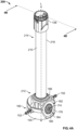
FIG. 4A is an isometric view of a probe assembly of a coupler according to one embodiment; -
FIG. 4B is a cross-sectional view of the probe assembly ofFIG. 4A taken alongline 4B-4B; -
FIG. 5 is a partial exploded view of a base end of the probe assembly ofFIG. 4 ; -
FIG. 6 is a partial isometric view of a base end of a probe assembly of a closed transfer system coupler according to another embodiment of the invention; -
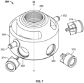
FIG. 7 is a partial exploded view of the base end ofFIG. 6 ; -
FIG. 8 is a partial isometric view of a probe end of a probe assembly of a closed transfer system coupler according to one embodiment; -
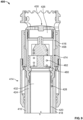
FIG. 9 is a partial cross-sectional view of the probe assembly ofFIG. 8 taken along line 9-9; and -
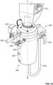
FIG. 10 is an isometric view of a closed transfer system coupler according to one embodiment. - Corresponding reference characters indicate corresponding parts throughout the several views. Although the drawings represent embodiments of the disclosure, the drawings are not necessarily to scale and certain features may be exaggerated in order to better illustrate and explain the embodiments of the disclosure.
- Before any embodiments of the invention are explained in detail, it is to be understood that the invention is not limited in its application to the details of construction and the arrangement of components set forth in the following description or illustrated in the following drawings. The invention is capable of other embodiments and of being practiced or of being carried out in various ways, as long as they fall within the scope of the appended claims. Also, it is to be understood that the phraseology and terminology used herein is for the purpose of description and should not be regarded as limiting. The use of "including," "comprising," or "having" and variations thereof herein is meant to encompass the items listed thereafter and equivalents thereof as well as additional items. Unless specified or limited otherwise, the terms "mounted," "connected," "supported," and "coupled" and variations thereof are used broadly and encompass both direct and indirect mountings, connections, supports, and couplings. Further, "connected" and "coupled" are not restricted to physical or mechanical connections or couplings. The above applies within the scope of the appended claims.
- The following discussion is presented to enable a person skilled in the art to make and use embodiments of the invention within the scope of the claims. Various modifications to the illustrated embodiments will be readily apparent to those skilled in the art, and the generic principles herein can be applied to other embodiments and applications without departing from embodiments of the invention. Thus, embodiments of the invention are not intended to be limited to embodiments shown, but are to be accorded the widest scope consistent with the principles and features disclosed herein. The following detailed description is to be read with reference to the figures, in which like elements in different figures have like reference numerals. The figures, which are not necessarily to scale, depict selected embodiments and are not intended to limit the scope of embodiments of the invention. Skilled artisans will recognize the examples provided herein have many useful alternatives and fall within the scope of the claims.
- Closed transfer systems are useful in chemical transfer applications to protect users from exposure to a chemical being transferred. Conventional closed transfer systems typically include at least a locking mechanism, a transfer mechanism, and a cleaning mechanism. The locking mechanism is designed to securely lock a container full of chemicals into a fluid tight configuration with a closed transfer system coupler. The closed transfer system allows air to be introduced into the container through a one-way valve to allow the chemical to empty from the container by gravity feed or vacuum suction. The cleaning mechanism provides a rinse solution to rinse out the container and to rinse off parts of the coupling mechanism that have been exposed to the chemical during transfer. All of these functions are performed in a fluid tight environment to prevent users from exposure.
- In some conventional closed transfer systems, the one-way valve that introduces air into the chemical container cannot create a perfect fluid tight seal over many cycles of closed transfer system use or during the cleaning cycle. Thus, the one-way valve can leak small quantities of fluid over time. Thus, it can be useful to provide a backup valve that keeps any leaked fluid from exiting the system.
-
FIGS. 1-3 illustrate acoupler 10 for a closed transfer system. Thecoupler 10 has ahousing 20 that can be substantially cylindrical. Thehousing 20 includes a base rinseinlet 64 and anoutlet 30 that each extend outwardly from thehousing 20 to partially define a fluid flow path through thecoupler 10. In some embodiments, the base rinseinlet 64 is provided on a bottom end of thehousing 20 and is designed to be coupled to a water source, while theoutlet 30 protrudes outwardly from an upper end of thehousing 20 adjacent acontainer 12. Theoutlet 30 is designed to be coupled to a vacuum or pump to pull fluid (e.g., water or chemicals) from thehousing 20 out of theoutlet 30 and away from thecoupler 10. The vacuum or pump can be omitted, as theoutlet 30 can also remove fluid from thecontainer 12 using gravity. In some embodiments, the base rinseinlet 64 and theoutlet 30 each extend outwardly from thehousing 20, and can be coupled to fluid sources and fluid receptacles, respectively. Aprobe assembly 100, which includes the base rinseinlet 64, is at least partially received within thehousing 20 and can extend completely through thehousing 20. Theprobe assembly 100 can selectively restrict fluid flow between the base rinseinlet 64 and theoutlet 30. In some embodiments, theprobe assembly 100 may be disposed entirely within thehousing 20. - The
probe assembly 100 includes aprobe 110 that is provided in the form of an elongate tube with a longitudinal axis that aligns with the axis X-X. Theprobe 110 has abase end 112 and aprobe end 114 that includes aprobe tip 116. Theprobe 110 further includes anouter tube 118 and aninner tube 119. Theinner tube 119 forms ahollow air channel 32. Theinner tube 119 is positioned inside of theouter tube 118, forming ahollow liquid channel 24 in the interstitial space between the outer wall of theinner tube 119 and the inner wall of theouter tube 118. Theinner tube 119 is open to atmosphere at thebase end 112. - The
probe assembly 100 can be moved relative to thehousing 20 between a first position (shown inFIGS. 1 and2 ) and a second position (shown inFIG. 3 ) along a longitudinal axis X-X. When theprobe assembly 100 is in the first position, theprobe tip 116 can be entirely received within thehousing 20, and thecoupler 10 is "closed." Theprobe assembly 100 is positioned within the fluid flow path between thecontainer 12 and theoutlet 30 to restrict the flow of water or chemicals out of thecontainer 12. - To "open" the
coupler 10, theprobe assembly 100 can be moved to the second position. In the second position, theprobe assembly 100 extends upwardly from thehousing 20 further than in the first position, and can extend at least partially into thecontainer 12 positioned above thecoupler 10. When theprobe assembly 100 is moved upwardly to the second position, theprobe assembly 100 opens the flow path between thecontainer 12 and theoutlet 30, and the contents of thecontainer 12 can flow to theoutlet 30. - The
probe assembly 100 can be moved between the first position and the second position using a handle 26 (seeFIG. 1 ). Thehandle 26 can be coupled to theprobe assembly 100, and can extend outwardly from thehousing 20 to be manipulated by a user. In some embodiments, thehandle 26 is coupled to adisk 16 that is received around theprobe assembly 100 and positioned within thehousing 20. Thehandle 26 can be rotated or raised, which in turn causes thedisk 16 andprobe assembly 100 to rotate or raise. In some embodiments, aslot 18 is formed in thehousing 20 to restrict the allowable motion of the handle 26 (and probe assembly 100) relative to thehousing 20. - After the contents of the
container 12 are accessed by thecoupler 10 and a desired amount of fluid can be emptied from thecontainer 12, thecontainer 12 and thecoupler 10 can be rinsed. To perform the rinsing process, thecoupler 10 is placed in communication with a water source (not shown). In some embodiments, the water source is coupled to the base rinseinlet 64, which can be formed as a hole extending through theouter tube 118 of theprobe assembly 100. Rinse water is received through the base rinseinlet 64, which then fills and flows upwardly through ahollow liquid channel 24 formed within theprobe assembly 100. In some embodiments, theinner tube 119 andouter tube 118 are positioned concentrically about the longitudinal axis X-X. Rinse water continues to travel upward in thehollow liquid channel 24 until it reaches aprobe liquid outlet 127. Theprobe liquid outlet 127 can be provided as a slot extending through theouter tube 118 of theprobe assembly 100, which allows water to exit thehollow liquid channel 24 and theprobe assembly 100 to an external environment. In addition to providing rinse water, theprobe assembly 100 provides air into thecontainer 12, which aids the flow of liquid out of thecontainer 12 to theoutlet 30. In some embodiments, aninlet 154 is formed at the bottom of theinner tube 119 to supply ambient air from the environment. - Referring more particularly to the
probe tip 116, theprobe tip 116 includes aprobe air outlet 125 and aprobe liquid outlet 127, as best seen inFIG. 3 . Theprobe air outlet 125 includes at least one primary one-way valve 129, such as an elastomer umbrella valve, to prevent the back flow of liquid into theprobe tip 116. In some forms, theprobe air outlet 125 is configured to provide a single fluid path or a plurality of fluid paths in parallel, each having a respective one-way valve to prevent the back flow of liquid into theprobe tip 116. - In some instances, the
primary valve 129 is provided in the form of a one-way umbrella valve. Theprimary valve 129 is coupled to aperforated plate 78 and selectively covers and uncovers through-holes 84 during use. When the pressure differential between the air within the inner tube 119 (which is approximately atmospheric) and the fluid within thecontainer 12 crosses a threshold value, air is sucked into theinlet 154 and upward through theinner tube 119. The pressure differential causes the resilient elastomeric material of theprimary valve 129 to flex upward, uncovering the through-holes 84 in theperforated plate 78. - Referring further to
FIG. 2 , in some forms, in addition to the at least one primary one-way valve 129, theprobe assembly 100 includes at least one secondary one-way valve 74. Theprimary valve 129 is designed to interface directly with the fluid inside of thecontainer 12, releasing ambient air into thecontainer 12 while preventing the backflow of fluid chemicals into theprobe 110. In some embodiments, one or more one-way valves can function asprimary valves 129 that interface directly with the container fluid. The size, shape, and number ofprimary valves 129 is selected to provide for a sufficient volume of air flow into thecontainer 12. - The secondary one-
way valve 74 acts as a second backup barrier to prevent fluid from thecontainer 12 from leaking into theprobe 110. Thesecondary valve 74 can also temporarily take over for the function of theprimary valve 129 in the instance of completeprimary valve 129 failure. Thesecondary valve 74 is positioned upstream of theprimary valve 129 such that air flows in through theinlet 154 and past thesecondary valve 74 toward theprimary valve 129 when fluid is emptying from thecontainer 12, and thesecondary valve 129 can be located at any number of positions between thebase end 112 and theprobe tip 116 substantially proximal to theprimary valve 129. Thesecondary valve 74 interfaces with the container fluid only indirectly, when fluid leaks through theprimary valve 129. In some embodiments, one or more one-way valves can function assecondary valves 74 that do not interface directly with the container fluid. In some instances, thesecondary valve 74 is provided in the form of a duck bill valve. The size, shape, and number ofsecondary valves 74 is selected to ensure that backflow past thesecondary valve 74 is prevented. The opening pressure of thesecondary valve 74 is designed with a differential opening pressure that is substantially equal to or lower than the differential opening pressure of theprimary valve 129 so that thesecondary valve 74 has little to no impact on the performance of theprimary valve 129. Thesecondary valve 74 is also designed to provide a volume of air flow at a substantially equal to or greater flow rate than theprimary valve 129 so as not to throttle theprimary valve 129. -
FIGS. 4-6 illustrate analternative probe assembly 200 that can be integrated into a coupler for a closed transfer system such as thecoupler 10 ofFIGS. 1-3 or acoupler 500 ofFIG. 10 described below. Theprobe assembly 200 includes abase 160, aprobe 210, arotatable nozzle 158, one or more primary one-way valves 230, and a secondary one-way valve 174. As shown inFIGS. 4A and4B , theprobe 210 is provided in the form of an elongate tube with a longitudinal axis that aligns with the axis L. Theprobe 210 has abase end 212 and aprobe end 214 that includes a probe tip 216 (seeFIG. 4B ). Theprobe 210 further includes anouter tube 218 and aninner tube 220. Theinner tube 220 forms ahollow air channel 232. Theinner tube 220 is positioned inside of theouter tube 218, forming a hollowliquid channel 224 in the interstitial space between the outer wall of theinner tube 220 and the inner wall of theouter tube 218. Theouter tube 218 of theprobe 210 is sized and shaped to be received within abore 166 and provide a fluid tight connection with thebase 160. In one instance, theouter tube 218 can include threads provided on thebase end 212 to screw into threads provided in thebore 166. Theouter tube 218 can also be sized and shaped to press fit into thebore 166, or a fluid tight junction between theouter tube 218 and thebore 166 can otherwise be provided by conventionally known structures and methods. - The
base 160 includes abase air inlet 162, a base rinse inlet 164 (seeFIG. 4B ), and thebore 166 designed to receive theprobe assembly 200. Thebase 160 defines a cylindricalouter surface 150 with a center point that aligns with the longitudinal axis L. Twoposts 152 protrude outwardly and away from theouter surface 150 along an axis that is perpendicular to axis L. The center point of thebore 166 aligns with the axis L. - The base 160 further includes a liquid chamber 168 (see
FIG. 2 ) in fluid communication with the base rinseinlet 164 and anair chamber 170 in fluid communication with thebase air inlet 162. Thebase air inlet 162 is provided in the form of a circular opening that is positioned on theouter surface 150. Thebase air inlet 162 is titled at an angle from axis L with the top of thebase air inlet 162 angled toward the center of thebase 160, extending inwardly from theouter surface 150. The bottom surface of theair chamber 170 is partially sloped downwardly and away from thebase air inlet 162 and is positioned slightly below the bottom of thebase air inlet 162, forming a shallow reservoir. Thus, if a small amount of liquid falls into theair chamber 170 from theprobe 210, the fluid will reside at the bottom surface of theair chamber 170 away from thebase air inlet 162 when thecoupler 10 is upright. In some forms, the bottom surface of theair chamber 170 is perpendicular to the axis L and thebase air inlet 162 is parallel to the axis L when thecoupler 10 is upright. In some forms, theair chamber 170 includes a reservoir that extends downward from the bottom surface of theair chamber 170 to catch any liquid that falls from theprobe 210. - Referring to
FIG. 4B , theprobe tip 216 includes aprobe air outlet 226 and aprobe liquid outlet 228. Theprobe air outlet 226 provides two parallel fluid paths leading out of theprobe tip 216. Each fluid path includes a correspondingprimary valve 230, such as an elastomer umbrella valve, to prevent the back flow of liquid into theprobe tip 216. In some forms, theprobe air outlet 226 is configured to provide a single fluid path or a plurality of fluid paths in parallel, each having a respectiveprimary valve 230 to prevent the back flow of liquid into theprobe tip 216. The size, shape, and number ofprimary valves 230 is selected to provide for a sufficient volume of air flow into thecontainer 12. When theprobe 210 is coupled to thebore 166, thehollow air channel 232 of theinner tube 220 is in fluid communication with thebase air inlet 162 and theair chamber 170. Also, when theprobe 210 is coupled to thebore 166, the hollowliquid channel 224 is in fluid communication with the base rinseinlet 164 and theliquid chamber 168. - The
primary valves 230 are designed to interface directly with the fluid inside of thecontainer 12, releasing ambient air into thecontainer 12 while preventing the backflow of fluid chemicals into theprobe 210. Thesecondary valve 174 is a second backup barrier designed to prevent fluid from thecontainer 12 leaking into theprobe 210. Thesecondary valve 174 is positioned upstream of theprimary valve 230 such that air flows past thesecondary valve 174 toward theprimary valve 230 when fluid is emptying from thecontainer 12. Thesecondary valve 174 interfaces with the container fluid only indirectly, when fluid leaks through theprimary valve 230. The size, shape, and number ofsecondary valves 174 is selected to ensure that backflow past thesecondary valve 174 is prevented. The opening pressure of thesecondary valve 174 is designed with a differential opening pressure that is substantially equal to or lower than the differential opening pressure of theprimary valve 230 so that thesecondary valve 174 has little to no impact on the performance of theprimary valve 230. Thesecondary valve 174 is also designed to provide a volume of air flow at a substantially equal to or greater flow rate than theprimary valve 230 so as not to throttle theprimary valve 230. - The
secondary valve 174 is fitted into thebase air inlet 162 to selectively allow air into theair chamber 170 of thebase 160. As shown inFIG. 5 , which disclose an example not covered by the claims, a recessedledge 176 is formed around the rim of thebase air inlet 162. The recessedledge 176 is sized and shaped to receive aperforated plate 178. Theperforated plate 178 is seated into and coupled to the recessedledge 176 forming a fluid tight seal. Anelastomer umbrella valve 180 is coupled to theperforated plate 178 and positioned so the canopy of theumbrella valve 180 selectively covers and uncovers through-holes 184 provided in theperforated plate 178. Theumbrella valve 180 is oriented to extend into theair chamber 170, thus acting as a one-way valve at thebase air inlet 162. In some embodiments, thesecondary valve 174 is provided in the form of another type of one-way valve such as a poppet valve, ball valve, or other check valve that opens under a low pressure differential and provides a sufficient volume of air flow for evacuation of fluid from thecontainer 12. In some forms, one or more parts of thesecondary valve 174 are molded or machined integrally into thebase 160. In some forms, thesecondary valve 174 is located in any number of positions along the air pathway between thebase air inlet 162 to theprimary valves 230 to act as a backup forprimary valves 230. In some forms, thesecondary valve 174 is in fluid communication with thehollow air channel 232 of theinner tube 220, but is positioned within thehousing 20 at a location offset from theprobe assembly 200. -
FIGS. 6 and7 illustrate abase 360 for theprobe assembly 200. Thebase 360 includes a plurality ofbase air inlets 362, a base rinse inlet (not shown), and abore 366 designed to receive theprobe assembly 200. Twoposts 352 extend outwardly on opposing sides of thebase 360 and away from anouter surface 350 along an axis that is perpendicular to longitudinal axis M. Theposts 352 are designed to interface with thehousing 20. Similar to thebase 160, thebase 360 includes a liquid chamber (not shown) in fluid communication with the base rinse inlet (not shown) and an air chamber (not shown) in fluid communication with thebase air inlets 362. Thebase air inlets 362 are provided in the form of circular openings that are positioned in a radial array along theouter surface 350. One-waysecondary valves 374 are sized to correspond to thebase air inlets 362 and are fitted into thebase air inlets 362 to selectively allow air into the air chamber (not shown) of thebase 360. Thesecondary valves 374 are provided in the form of poppet valves. In some embodiments, thesecondary valves 374 are provided in the form of another type of one-way valve such as an elastomer umbrella valve or other check valve that opens under a low pressure differential and provides a sufficient volume of air flow for evacuation of fluid from thecontainer 12. In some forms, one or more parts of thesecondary valves 374 are molded or machined integrally into thebase 360. If, during use, any small amount of fluid leaks through theprimary valves 230, thesecondary valves 374 act as backup valves to prevents the fluid from exiting thecoupler 10, thus providing additional user protection. In some forms, providing multiplesecondary valves 374 in lieu of a single, larger secondary valve, like thesecondary valve 174 of thebase 160, can save space within thehousing 20, which provides a more compact arrangement for thebase 360. -
FIGS. 8 and9 illustrate analternative probe assembly 400 that can be integrated into a coupler for a closed transfer system such as thecoupler 10 ofFIGS. 1-3 or thecoupler 500 ofFIG. 10 . Theprobe assembly 400 includes a base (not shown), aprobe 410, and arotatable nozzle 458. Theprobe 410 has a base end (not shown) and aprobe end 414 that includes aprobe tip 416. Theprobe 410 further comprises anouter tube 418 and aninner tube 420. Theinner tube 420 forms ahollow air channel 432. Theinner tube 420 is positioned inside of theouter tube 418, forming a hollowliquid channel 424 in the interstitial space between the outer wall of theinner tube 420 and the inner wall of theouter tube 418. Theprobe tip 416 includes aprobe air outlet 426 and aprobe liquid outlet 428. Theprobe air outlet 426 includes a one-wayprimary valve 430, such as an elastomer umbrella valve covering a perforated disc, to prevent back flow of fluid into theprobe tip 416. In some forms, theprobe air outlet 426 is configured to provide a plurality of air paths in parallel, each having a respective one-wayprimary valve 430 to prevent back flow through theprobe tip 416 and into thehollow air channel 432. - As shown in
FIG. 9 , a one-waysecondary valve 474 is disposed within thehollow air channel 432 at theprobe end 414 of theprobe 410, upstream of, and beneath, theprimary valve 430. Thesecondary valve 474 can be located proximal to theprimary valve 430 and can be provided in the form of a poppet valve having apiston 480 and aspring 482. The location of thesecondary valve 474 can be optimized by varying the distance between thesecondary valve 474 and theprimary valve 430. In some forms, thesecondary valve 474 is positioned directly adjacent to theprimary valve 430. In some forms, thesecondary valve 474 is located in any number of positions along thehollow air channel 432 to act as a backup for theprimary valve 430. The opening pressure of thesecondary valve 474 is designed with a differential opening pressure that is substantially equal to or lower than the differential opening pressure of theprimary valve 430 so that thesecondary valve 474 has little to no impact on the performance of theprimary valve 430. Thesecondary valve 474 is also designed to provide a volume of air flow at a substantially equal to or greater flow rate than theprimary valve 430 so as not to throttle theprimary valve 430. - The
secondary valve 474 selectively controls the flow of air out of theprobe air outlet 426 when it is urged open by differential pressure. If, during use, any small amount of fluid leaks through theprimary valve 430, thesecondary valve 474 prevents the fluid from exiting thecoupler 10, thus providing additional user protection. In some embodiments, thesecondary valve 474 is provided in the form of another type of one-way valve such as an umbrella valve or other check valve that opens under a low pressure differential and provides a sufficient volume of air flow for evacuation of fluid from thecontainer 12. In some forms, one or more parts of thesecondary valve 474 are molded or machined integrally into theinner tube 420 or theprobe tip 416. - The embodiments described herein should not be construed as limiting with respect to the specific parts described for said embodiment. For example, the
base probe assemblies probe assemblies probe tips probe assembly secondary valves -
FIG. 10 illustrates analternative coupler 500 within which any of theaforementioned probe assemblies coupler 500 includes ahousing 520 with a mountingbracket 522 designed to physically secure thecoupler 500 to a structure such as a chemical sprayer. Thehousing 520 is defined by a substantially cylindrical sidewall and provided with a longitudinal axis N. Alocking mechanism 524 is provided on the distal end of thehousing 520 to receive and secure acontainer 512. Thelocking mechanism 524 includes ahandle 526, and anopening 528 to receive a cap of thecontainer 512. Once the cap of thecontainer 512 is fitted to thecoupler 500, thehandle 526 is rotated radially about thecoupler 500, and thelocking mechanism 524 firmly secures the cap of thecontainer 512 into a fluid tight configuration with thecoupler 500. Thecoupler 500 further includes anoutlet 530 protruding outwardly from the outer wall of thehousing 520. Theoutlet 530 can be coupled to a pump to provide vacuum suction at theoutlet 530, which allows the fluid that has drained from thecontainer 512 into thecoupler 500 to be transferred to a sprayer or other chemical application mechanism (not shown). Once thelocking mechanism 524 has been actuated, thehandle 526 can be further rotated, which selectively actuates theprobe assembly probe assembly container 512 to theoutlet 530 without exposing the user to the chemical, as described in further detail below. - The
coupler 500 further includes anintegrated cleaning mechanism 540 extending from the outer wall of thehousing 520. Thecleaning mechanism 540 includes a rinsewater line 542 and acontrol valve 544. A pressurized source of rinse water can be coupled to the rinsewater line 542 so that when thecontrol valve 544 is actuated, rinse water is provided to the probe assembly (e.g., one ofprobe assemblies water line 542. Thecoupler 500 also includes a cap rinselock 532, which prevents thecontainer 512 from decoupling from thecoupler 500 while the container cap is being rinsed. - When outfitted with the
probe assembly coupler container container coupler container container outlet container coupler handle handle 26, 256 theprobe assembly housing probe tip container probe tip container container outlet probe assembly base air inlet 162, 362 (or inlet 154) past thesecondary valve hollow air channel probe air outlet primary valves container - In some instances, fluid from the
container primary valves probe tip hollow air channel secondary valve coupler - After the contents of the
container coupler container container coupler coupler inlet inlet hollow liquid channel probe assembly inner tube outer tube hollow liquid channel probe liquid outlet probe liquid outlet outer tube probe assembly hollow liquid channel probe assembly probe assembly container container outlet - Thus, an improved coupler for a closed transfer system is provided. The coupler can include a probe assembly with one or more one-way primary valves for allowing air to flow into a container to be emptied of a fluid. A plurality of secondary one-way valves are located upstream of the one or more one-way valves. Accordingly, if, during use, any fluid leaks past the primary valve into the probe assembly, the secondary valves can prevent fluid from exiting the coupler. These benefits among other benefits are provided by this disclosure.
- It will be appreciated by those skilled in the art that while the invention has been described above in connection with particular embodiments and examples, the invention is not necessarily so limited, and that numerous other embodiments, examples, uses, modifications and departures from the embodiments, examples and uses are intended to be encompassed by the claims attached hereto. Various features and advantages of the invention are set forth in the following claims.
- For the sake of completeness, it is also stated that the term "comprising" does not exclude other elements or steps, the term "a" or "an" does not exclude a plurality, a single means/unit/feature may fulfil the functions of several means recited in the claims and any reference signs in the claims shall not be construed as limiting the scope of the claims.
Claims (14)
- A probe assembly (200) for a closed transfer system coupler configured to selectively engage a container coupled to the coupler in a fluid tight configuration, the probe assembly comprising:a base (160) including a base air inlet (162);a probe (210) defining a hollow air channel (232) in fluid communication with the base air inlet, the probe including at least one primary valve (230); anda plurality of secondary valves (374) configured to selectively allow air into the hollow air channel in parallel.
- The probe assembly of claim 1, wherein the probe includes a first end (216) and a second end (212), the first end and the second end configured as opposing ends of the probe; and
the at least one primary valve is proximate the first end and the secondary valves (374) are proximate the second end. - The probe assembly (100) of claim 2, further comprising:
a probe tip (216) positioned at the first end, the hollow air channel (232) extending from the second end (212) to the first end (216), the second end being coupled to the base such that the hollow air channel is in fluid communication with the base air inlet and the probe tip. - The probe assembly of claim 3, wherein the base air inlet (162) is provided in the form of a plurality of openings positioned in a radial array along an outer surface of the base.
- The probe assembly of claim 3 or claim 4, wherein the secondary valves (374) are configured to selectively allow air into the hollow air channel; and, optionally or preferably, wherein each of the plurality of openings is configured to receive a corresponding secondary valve.
- The probe assembly of claim 3, claim 4 or claim 5, wherein the secondary valves (374):(i) comprises poppet valves;(ii) are configured with a differential opening pressure that is less than or substantially equal to a differential opening pressure of the at least one primary valve; and/or(iii) provide a volume of air flow substantially equal to or greater than a volume of air flow provided by the at least one primary valve.
- The probe assembly of claim 3 or of any of claims 4 to 6, wherein the probe comprises an outer tube (218) having threads provided on the second end (212), the threads being sized and shaped to provide a fluid tight connection with threads provided on the base.
- The probe assembly of claim 3 or of any of claims 4 to 7, wherein the probe comprises:an outer tube (218) having an inner wall; and an inner tube positioned inside of the outer tube, an inside of the inner tube forming the hollow air channel, the inner tube including an outer wall, wherein an interstitial space between the outer wall of the inner tube and the inner wall of the outer tube forms a hollow liquid channel;and, optionally or preferably, wherein the base includes a base rinse inlet (162) in fluid communication with the hollow liquid channel.
- The probe assembly of claim 3 or of any of claims 4 to 8, wherein the at least one primary valve comprises at least one umbrella valve configured to allow air to flow from the hollow air channel out of the probe tip.
- The probe assembly of claim 3, wherein the base includes an air chamber (170) in fluid communication with the base air inlet and the hollow air channel, the air chamber including a bottom surface that is positioned below the base air inlet to form a reservoir.
- The probe assembly of any of claims 3 to 10, wherein the probe is arranged along a longitudinal axis and the base air inlet is tilted at an angle with respect to the longitudinal axis.
- The probe assembly of any of claims 3 to 11, wherein a top of the base air inlet is angled toward a center of the base.
- The probe assembly of any of claims 3 to 12, wherein the at least one primary valve is provided as a pair of umbrella valves configured to allow air to flow in parallel from the hollow air channel out of the probe tip.
- The probe assembly of any of claims 3 to 13, wherein the at least one primary valve and the secondary valves (374) are configured to selectively allow air to flow into the base air inlet and into an air chamber formed within the base, the air chamber being in fluid communication with the hollow air channel.
Priority Applications (1)
| Application Number | Priority Date | Filing Date | Title |
|---|---|---|---|
| EP25170809.5A EP4596488A3 (en) | 2020-06-09 | 2021-06-09 | Backup valve for closed transfer coupler |
Applications Claiming Priority (1)
| Application Number | Priority Date | Filing Date | Title |
|---|---|---|---|
| US202062705066P | 2020-06-09 | 2020-06-09 |
Related Child Applications (1)
| Application Number | Title | Priority Date | Filing Date |
|---|---|---|---|
| EP25170809.5A Division EP4596488A3 (en) | 2020-06-09 | 2021-06-09 | Backup valve for closed transfer coupler |
Publications (2)
| Publication Number | Publication Date |
|---|---|
| EP3922595A1 EP3922595A1 (en) | 2021-12-15 |
| EP3922595B1 true EP3922595B1 (en) | 2025-04-16 |
Family
ID=76374902
Family Applications (2)
| Application Number | Title | Priority Date | Filing Date |
|---|---|---|---|
| EP21178556.3A Active EP3922595B1 (en) | 2020-06-09 | 2021-06-09 | Backup valve for closed transfer coupler |
| EP25170809.5A Pending EP4596488A3 (en) | 2020-06-09 | 2021-06-09 | Backup valve for closed transfer coupler |
Family Applications After (1)
| Application Number | Title | Priority Date | Filing Date |
|---|---|---|---|
| EP25170809.5A Pending EP4596488A3 (en) | 2020-06-09 | 2021-06-09 | Backup valve for closed transfer coupler |
Country Status (2)
| Country | Link |
|---|---|
| US (2) | US12264061B2 (en) |
| EP (2) | EP3922595B1 (en) |
Families Citing this family (3)
| Publication number | Priority date | Publication date | Assignee | Title |
|---|---|---|---|---|
| US12128460B2 (en) * | 2021-09-09 | 2024-10-29 | Pentair Flow Technologies, Llc | Apparatus to direct flow of fluid |
| EP4491292A1 (en) * | 2023-07-14 | 2025-01-15 | Lechler GmbH | Coupling device for canister |
| DE202023103948U1 (en) * | 2023-07-14 | 2023-07-24 | Lechler Gmbh | Coupling device for canisters |
Family Cites Families (7)
| Publication number | Priority date | Publication date | Assignee | Title |
|---|---|---|---|---|
| US20080314930A1 (en) | 2006-04-26 | 2008-12-25 | Green Theodore A | Liquid container valve system |
| WO2011119122A1 (en) | 2009-11-16 | 2011-09-29 | Ugur Eroglu | Water transfer apparatus for 1,5 and 19 lt. pet bottles and demijohns |
| US20130292493A1 (en) | 2012-05-01 | 2013-11-07 | Finishing Brands Holdings Inc. | Vent system for a gravity feed spray device |
| US9580292B2 (en) * | 2014-03-12 | 2017-02-28 | The Procter & Gamble Company | Vented tap dispenser for liquid |
| DK3558861T3 (en) | 2016-12-22 | 2024-01-15 | Basf Se | DEVICE WITH PROBE FOR CONNECTING AND OPENING A CONTAINER |
| RO132308A0 (en) | 2017-07-26 | 2017-12-29 | Vasile Curcan | Liquid dispenser |
| US11214479B2 (en) * | 2017-11-10 | 2022-01-04 | Pentair Flow Technologies, Llc | Probe assembly for use in a closed transfer system |
-
2021
- 2021-06-09 EP EP21178556.3A patent/EP3922595B1/en active Active
- 2021-06-09 US US17/303,856 patent/US12264061B2/en active Active
- 2021-06-09 EP EP25170809.5A patent/EP4596488A3/en active Pending
-
2025
- 2025-04-01 US US19/097,702 patent/US20250230029A1/en active Pending
Also Published As
| Publication number | Publication date |
|---|---|
| US12264061B2 (en) | 2025-04-01 |
| EP4596488A3 (en) | 2025-08-27 |
| EP4596488A2 (en) | 2025-08-06 |
| US20210380396A1 (en) | 2021-12-09 |
| US20250230029A1 (en) | 2025-07-17 |
| EP3922595A1 (en) | 2021-12-15 |
Similar Documents
| Publication | Publication Date | Title |
|---|---|---|
| US20250230029A1 (en) | Backup valve for closed transfer coupler | |
| EP2160252B1 (en) | Self regulating vent for a paint supply vessel | |
| US6619318B2 (en) | Multiple flow rate eductive dispenser | |
| US6688499B2 (en) | Liquid dispenser with screw pump | |
| EP2033905B1 (en) | Beverage container | |
| US8640930B2 (en) | Vent tube apparatus and method | |
| US5341967A (en) | Trigger sprayer for upright or inverted dispensing without leakage | |
| US11795047B2 (en) | Probe assembly for use in a closed transfer system | |
| JP2004510659A (en) | Plug for fluid distribution | |
| TW201441142A (en) | Pumps with container vents | |
| CA2466446C (en) | Dispenser for dispensing a fluid, housing for such a dispenser, storage holder destined for placement therein and arrangement for the dosed pumping of a fluid from a fluid reservoir | |
| AU2001296840A1 (en) | Fluid dispensing closure | |
| JPH09501640A (en) | Assembly for simultaneous discharge of multiple fluids | |
| KR101278779B1 (en) | Portable liquid dispenser | |
| EP0010962B1 (en) | Improvements in portable toilets | |
| JP2653662B2 (en) | Liquid storage and transfer equipment | |
| CN112638820A (en) | Valved connector for closed loop liquid dispensing system | |
| US10919676B2 (en) | Lid with ventilation system | |
| CA2613929A1 (en) | Closure for can filler port and can vent | |
| WO2024089611A1 (en) | Trigger dispensing device for upside down operation | |
| GB2290279A (en) | Rigid walled container with liquid outlet and air inlet | |
| JP6604876B2 (en) | Trigger type liquid ejection container | |
| CN223255699U (en) | Liquid storage container for clothing processing equipment and clothing processing equipment | |
| JP3675765B2 (en) | Inner plug for air pot | |
| JPH0726996Y2 (en) | Pump injection type liquid container |
Legal Events
| Date | Code | Title | Description |
|---|---|---|---|
| PUAI | Public reference made under article 153(3) epc to a published international application that has entered the european phase |
Free format text: ORIGINAL CODE: 0009012 |
|
| STAA | Information on the status of an ep patent application or granted ep patent |
Free format text: STATUS: THE APPLICATION HAS BEEN PUBLISHED |
|
| AK | Designated contracting states |
Kind code of ref document: A1 Designated state(s): AL AT BE BG CH CY CZ DE DK EE ES FI FR GB GR HR HU IE IS IT LI LT LU LV MC MK MT NL NO PL PT RO RS SE SI SK SM TR |
|
| B565 | Issuance of search results under rule 164(2) epc |
Effective date: 20211108 |
|
| STAA | Information on the status of an ep patent application or granted ep patent |
Free format text: STATUS: REQUEST FOR EXAMINATION WAS MADE |
|
| 17P | Request for examination filed |
Effective date: 20220615 |
|
| RBV | Designated contracting states (corrected) |
Designated state(s): AL AT BE BG CH CY CZ DE DK EE ES FI FR GB GR HR HU IE IS IT LI LT LU LV MC MK MT NL NO PL PT RO RS SE SI SK SM TR |
|
| GRAP | Despatch of communication of intention to grant a patent |
Free format text: ORIGINAL CODE: EPIDOSNIGR1 |
|
| STAA | Information on the status of an ep patent application or granted ep patent |
Free format text: STATUS: GRANT OF PATENT IS INTENDED |
|
| INTG | Intention to grant announced |
Effective date: 20240617 |
|
| GRAJ | Information related to disapproval of communication of intention to grant by the applicant or resumption of examination proceedings by the epo deleted |
Free format text: ORIGINAL CODE: EPIDOSDIGR1 |
|
| STAA | Information on the status of an ep patent application or granted ep patent |
Free format text: STATUS: REQUEST FOR EXAMINATION WAS MADE |
|
| GRAP | Despatch of communication of intention to grant a patent |
Free format text: ORIGINAL CODE: EPIDOSNIGR1 |
|
| STAA | Information on the status of an ep patent application or granted ep patent |
Free format text: STATUS: GRANT OF PATENT IS INTENDED |
|
| INTC | Intention to grant announced (deleted) | ||
| INTG | Intention to grant announced |
Effective date: 20241107 |
|
| GRAS | Grant fee paid |
Free format text: ORIGINAL CODE: EPIDOSNIGR3 |
|
| GRAA | (expected) grant |
Free format text: ORIGINAL CODE: 0009210 |
|
| STAA | Information on the status of an ep patent application or granted ep patent |
Free format text: STATUS: THE PATENT HAS BEEN GRANTED |
|
| AK | Designated contracting states |
Kind code of ref document: B1 Designated state(s): AL AT BE BG CH CY CZ DE DK EE ES FI FR GB GR HR HU IE IS IT LI LT LU LV MC MK MT NL NO PL PT RO RS SE SI SK SM TR |
|
| REG | Reference to a national code |
Ref country code: GB Ref legal event code: FG4D |
|
| REG | Reference to a national code |
Ref country code: CH Ref legal event code: EP |
|
| REG | Reference to a national code |
Ref country code: IE Ref legal event code: FG4D |
|
| REG | Reference to a national code |
Ref country code: DE Ref legal event code: R096 Ref document number: 602021029129 Country of ref document: DE |
|
| PGFP | Annual fee paid to national office [announced via postgrant information from national office to epo] |
Ref country code: DE Payment date: 20250630 Year of fee payment: 5 |
|
| PGFP | Annual fee paid to national office [announced via postgrant information from national office to epo] |
Ref country code: GB Payment date: 20250627 Year of fee payment: 5 |
|
| PGFP | Annual fee paid to national office [announced via postgrant information from national office to epo] |
Ref country code: FR Payment date: 20250625 Year of fee payment: 5 |
|
| PGFP | Annual fee paid to national office [announced via postgrant information from national office to epo] |
Ref country code: AT Payment date: 20250721 Year of fee payment: 5 |
|
| REG | Reference to a national code |
Ref country code: NL Ref legal event code: MP Effective date: 20250416 |
|
| PG25 | Lapsed in a contracting state [announced via postgrant information from national office to epo] |
Ref country code: NL Free format text: LAPSE BECAUSE OF FAILURE TO SUBMIT A TRANSLATION OF THE DESCRIPTION OR TO PAY THE FEE WITHIN THE PRESCRIBED TIME-LIMIT Effective date: 20250416 |
|
| REG | Reference to a national code |
Ref country code: AT Ref legal event code: MK05 Ref document number: 1785572 Country of ref document: AT Kind code of ref document: T Effective date: 20250416 |
|
| PG25 | Lapsed in a contracting state [announced via postgrant information from national office to epo] |
Ref country code: PT Free format text: LAPSE BECAUSE OF FAILURE TO SUBMIT A TRANSLATION OF THE DESCRIPTION OR TO PAY THE FEE WITHIN THE PRESCRIBED TIME-LIMIT Effective date: 20250818 Ref country code: ES Free format text: LAPSE BECAUSE OF FAILURE TO SUBMIT A TRANSLATION OF THE DESCRIPTION OR TO PAY THE FEE WITHIN THE PRESCRIBED TIME-LIMIT Effective date: 20250416 Ref country code: FI Free format text: LAPSE BECAUSE OF FAILURE TO SUBMIT A TRANSLATION OF THE DESCRIPTION OR TO PAY THE FEE WITHIN THE PRESCRIBED TIME-LIMIT Effective date: 20250416 |
|
| REG | Reference to a national code |
Ref country code: LT Ref legal event code: MG9D |
|
| PG25 | Lapsed in a contracting state [announced via postgrant information from national office to epo] |
Ref country code: GR Free format text: LAPSE BECAUSE OF FAILURE TO SUBMIT A TRANSLATION OF THE DESCRIPTION OR TO PAY THE FEE WITHIN THE PRESCRIBED TIME-LIMIT Effective date: 20250717 Ref country code: NO Free format text: LAPSE BECAUSE OF FAILURE TO SUBMIT A TRANSLATION OF THE DESCRIPTION OR TO PAY THE FEE WITHIN THE PRESCRIBED TIME-LIMIT Effective date: 20250716 |
|
| PG25 | Lapsed in a contracting state [announced via postgrant information from national office to epo] |
Ref country code: PL Free format text: LAPSE BECAUSE OF FAILURE TO SUBMIT A TRANSLATION OF THE DESCRIPTION OR TO PAY THE FEE WITHIN THE PRESCRIBED TIME-LIMIT Effective date: 20250416 |
|
| PG25 | Lapsed in a contracting state [announced via postgrant information from national office to epo] |
Ref country code: BG Free format text: LAPSE BECAUSE OF FAILURE TO SUBMIT A TRANSLATION OF THE DESCRIPTION OR TO PAY THE FEE WITHIN THE PRESCRIBED TIME-LIMIT Effective date: 20250416 |
|
| PG25 | Lapsed in a contracting state [announced via postgrant information from national office to epo] |
Ref country code: HR Free format text: LAPSE BECAUSE OF FAILURE TO SUBMIT A TRANSLATION OF THE DESCRIPTION OR TO PAY THE FEE WITHIN THE PRESCRIBED TIME-LIMIT Effective date: 20250416 |
|
| PG25 | Lapsed in a contracting state [announced via postgrant information from national office to epo] |
Ref country code: AT Free format text: LAPSE BECAUSE OF FAILURE TO SUBMIT A TRANSLATION OF THE DESCRIPTION OR TO PAY THE FEE WITHIN THE PRESCRIBED TIME-LIMIT Effective date: 20250416 |
|
| PG25 | Lapsed in a contracting state [announced via postgrant information from national office to epo] |
Ref country code: RS Free format text: LAPSE BECAUSE OF FAILURE TO SUBMIT A TRANSLATION OF THE DESCRIPTION OR TO PAY THE FEE WITHIN THE PRESCRIBED TIME-LIMIT Effective date: 20250716 |
|
| PG25 | Lapsed in a contracting state [announced via postgrant information from national office to epo] |
Ref country code: IS Free format text: LAPSE BECAUSE OF FAILURE TO SUBMIT A TRANSLATION OF THE DESCRIPTION OR TO PAY THE FEE WITHIN THE PRESCRIBED TIME-LIMIT Effective date: 20250816 |
|
| PG25 | Lapsed in a contracting state [announced via postgrant information from national office to epo] |
Ref country code: LV Free format text: LAPSE BECAUSE OF FAILURE TO SUBMIT A TRANSLATION OF THE DESCRIPTION OR TO PAY THE FEE WITHIN THE PRESCRIBED TIME-LIMIT Effective date: 20250416 |
|
| PG25 | Lapsed in a contracting state [announced via postgrant information from national office to epo] |
Ref country code: SM Free format text: LAPSE BECAUSE OF FAILURE TO SUBMIT A TRANSLATION OF THE DESCRIPTION OR TO PAY THE FEE WITHIN THE PRESCRIBED TIME-LIMIT Effective date: 20250416 Ref country code: DK Free format text: LAPSE BECAUSE OF FAILURE TO SUBMIT A TRANSLATION OF THE DESCRIPTION OR TO PAY THE FEE WITHIN THE PRESCRIBED TIME-LIMIT Effective date: 20250416 |
|
| REG | Reference to a national code |
Ref country code: DE Ref legal event code: R097 Ref document number: 602021029129 Country of ref document: DE |
|
| PG25 | Lapsed in a contracting state [announced via postgrant information from national office to epo] |
Ref country code: CZ Free format text: LAPSE BECAUSE OF FAILURE TO SUBMIT A TRANSLATION OF THE DESCRIPTION OR TO PAY THE FEE WITHIN THE PRESCRIBED TIME-LIMIT Effective date: 20250416 |
|
| PG25 | Lapsed in a contracting state [announced via postgrant information from national office to epo] |
Ref country code: EE Free format text: LAPSE BECAUSE OF FAILURE TO SUBMIT A TRANSLATION OF THE DESCRIPTION OR TO PAY THE FEE WITHIN THE PRESCRIBED TIME-LIMIT Effective date: 20250416 |
|
| PG25 | Lapsed in a contracting state [announced via postgrant information from national office to epo] |
Ref country code: SK Free format text: LAPSE BECAUSE OF FAILURE TO SUBMIT A TRANSLATION OF THE DESCRIPTION OR TO PAY THE FEE WITHIN THE PRESCRIBED TIME-LIMIT Effective date: 20250416 Ref country code: RO Free format text: LAPSE BECAUSE OF FAILURE TO SUBMIT A TRANSLATION OF THE DESCRIPTION OR TO PAY THE FEE WITHIN THE PRESCRIBED TIME-LIMIT Effective date: 20250416 |
|
| REG | Reference to a national code |
Ref country code: CH Ref legal event code: H13 Free format text: ST27 STATUS EVENT CODE: U-0-0-H10-H13 (AS PROVIDED BY THE NATIONAL OFFICE) Effective date: 20260127 |
|
| PG25 | Lapsed in a contracting state [announced via postgrant information from national office to epo] |
Ref country code: IT Free format text: LAPSE BECAUSE OF FAILURE TO SUBMIT A TRANSLATION OF THE DESCRIPTION OR TO PAY THE FEE WITHIN THE PRESCRIBED TIME-LIMIT Effective date: 20250416 |
|
| PG25 | Lapsed in a contracting state [announced via postgrant information from national office to epo] |
Ref country code: MC Free format text: LAPSE BECAUSE OF FAILURE TO SUBMIT A TRANSLATION OF THE DESCRIPTION OR TO PAY THE FEE WITHIN THE PRESCRIBED TIME-LIMIT Effective date: 20250416 |
|
| PG25 | Lapsed in a contracting state [announced via postgrant information from national office to epo] |
Ref country code: LU Free format text: LAPSE BECAUSE OF NON-PAYMENT OF DUE FEES Effective date: 20250609 |
|
| PLBE | No opposition filed within time limit |
Free format text: ORIGINAL CODE: 0009261 |
|
| STAA | Information on the status of an ep patent application or granted ep patent |
Free format text: STATUS: NO OPPOSITION FILED WITHIN TIME LIMIT |
|
| REG | Reference to a national code |
Ref country code: CH Ref legal event code: L10 Free format text: ST27 STATUS EVENT CODE: U-0-0-L10-L00 (AS PROVIDED BY THE NATIONAL OFFICE) Effective date: 20260225 |
|
| REG | Reference to a national code |
Ref country code: BE Ref legal event code: MM Effective date: 20250630 |
|
| 26N | No opposition filed |
Effective date: 20260119 |
|
| PG25 | Lapsed in a contracting state [announced via postgrant information from national office to epo] |
Ref country code: IE Free format text: LAPSE BECAUSE OF NON-PAYMENT OF DUE FEES Effective date: 20250609 |
|
| PG25 | Lapsed in a contracting state [announced via postgrant information from national office to epo] |
Ref country code: BE Free format text: LAPSE BECAUSE OF NON-PAYMENT OF DUE FEES Effective date: 20250630 |
|
| PG25 | Lapsed in a contracting state [announced via postgrant information from national office to epo] |
Ref country code: CH Free format text: LAPSE BECAUSE OF NON-PAYMENT OF DUE FEES Effective date: 20250630 |