EP0010962B1 - Improvements in portable toilets - Google Patents
Improvements in portable toilets Download PDFInfo
- Publication number
- EP0010962B1 EP0010962B1 EP79302393A EP79302393A EP0010962B1 EP 0010962 B1 EP0010962 B1 EP 0010962B1 EP 79302393 A EP79302393 A EP 79302393A EP 79302393 A EP79302393 A EP 79302393A EP 0010962 B1 EP0010962 B1 EP 0010962B1
- Authority
- EP
- European Patent Office
- Prior art keywords
- holding tank
- section
- portable toilet
- valve
- sections
- Prior art date
- Legal status (The legal status is an assumption and is not a legal conclusion. Google has not performed a legal analysis and makes no representation as to the accuracy of the status listed.)
- Expired
Links
Images


Classifications
-
- E—FIXED CONSTRUCTIONS
- E03—WATER SUPPLY; SEWERAGE
- E03D—WATER-CLOSETS OR URINALS WITH FLUSHING DEVICES; FLUSHING VALVES THEREFOR
- E03D5/00—Special constructions of flushing devices, e.g. closed flushing system
- E03D5/012—Special constructions of flushing devices, e.g. closed flushing system combined with movable closure elements in the bowl outlet
Definitions
- the present invention relates to portable toilets.
- Such portable toilets have holding tanks on which are removably mounted upper units which contain among other items, a a toilet bowl, a flush water storage tank and flush apparatus for flushing waste material from the bowl into the holding tank. It is the practice in each of these toilets to provide a valve assembly on the holding tank for opening and closing the tank inlet port that is in communication with the outlet from the toilet bowl.
- the tank contains a discharge spout with a closure cap, the spout normally being located in one of the side walls of the tank where it is visible and below the liquid line of the tank when the latter is full.
- flush apparatus that includes a nozzle for directing flush water into the bowl, a manually actuated bellows pump, or the like, for pumping flush water from the storage tank to the bowl, and a conduit connected to the discharge outlet of the pump and the inlet side of the nozzle for passage of the flush water. It is the general practice to provide check-valves in the pump apparatus to enable the pump to function properly and to permit carrying the portable toilet, or merely the upper unit thereof, with water in the storage tank without inadvertent spilling or discharge of the flush water through the discharge nozzle.
- the present invention provides a self- contained portable toilet that embodies several improved features that overcome inadequacies in the prior art toilets and that permit the toilets to be handled, manufactured and function in a more satisfactory manner.
- a portable toilet comprising a portable lower holding tank section and a portable upper seat section removably supported thereon, said seat section having top, side and bottom walls with an outlet port in its bottom wall and defining a bowl extending between said top and bottom walls and opening at the bottom to the outlet port, said holding tank section having a top wall and side and bottom walls forming a closed receptacle with an inlet port in its top wall in registry with said outlet port, and a valve assembly mounted on said holding tank section for opening and closing said inlet port, the holding tank section and the seat section having cooperable pairs of disengageable means in their respective top and bottom walls characterised in that said pairs of disengageable means are adjacent to a pair of opposite sides of the sections, that one of said cooperable pairs is in the form of interlocking means including hinge-like elements fixedly located in said top and bottom walls and interconnected to provide a hinge axis for pivotal movement of the seat section relative to the holding tank section, the seat section being disengageable from the holding tank section when
- the rear sides of the sections preferably define a cavity with the clasp means including a handle located in the cavity and movable transversely of the toilet in the cavity to move the clasp means between its released and secured positions.
- This construction and arrangement provides easy access to the handle for releasing the clasp means so that the upper section can be released from the lower section, and it also provides a sheltered area for the handle of the clasp mechanism to protect it from being damaged from exterior forces, such as might be present during movement of the portable toilet.
- Another preferred feature of the present invention lies in the construction and arrangement of the top wall of the holding tank and the bottom wall of the upper seat section so that the holding tank section has its discharge spout located in its top wall and at a level above that of the valve assembly.
- This construction and arrangement enables the user of the portable toilet to remove the closure cap for the spout and to introduce selected chemical preparations or the like into the holding tank while liquid contents are in the tank without the danger of spilling the contents. It also significantly reduces the sealing problems that are involved for assuring that leakage does not occur at the closure cap while the portable toilet is in use. Still further it conceals the closure cap and spout when the portable toilet is in its assembled position to provide a more aesthetically attractive portable toilet.
- the disengageable interlocking means are located adjacent to the front sides of the upper and lower sections, and the releasable clasp means are located adjacent to the rear sides of the sections so that the clasp means can be released and the rear of the seat section can be raised upward by pivotal movement of the seat section around the axis of the interlocking means, and the spout is located so that it projects upward and toward the rear of the holding tank section to facilitate removal of the closure cap therefrom and introduction of the selected chemicals into the holding tank.
- valve-and-nozzle assembly that is part of the flush means for pumping flush water from the storage tank in the upper section to the toilet bowl, the flush means including a pump in communication with the storage tank, a valve-and-nozzle assembly to discharge flush water into the bowl and a flexible conduit in communication with the pump and the valve-and-nozzle assembly.
- these components can be press-fitted together so as to reduce materially the cost of assembly.
- the valve-and-nozzle assembly is a unitary construction which provides a check- valve immediately adjacent to the nozzle so as to eliminate certain problems of inadvertent spilling from the flexible conduit during transportation of the portable toilet.
- valve-and-nozzle assembly Another feature of the valve-and-nozzle assembly is a collar arranged on the outer periphery of the valve body so that when the nozzle is snap-fitted into an aperture in the wall of the toilet bowl, the nozzle will be properly directed into the bowl to facilitate discharge of a single jet of flush water into the bowl to provide a vortex pattern of flow of the water therein to the bowl outlet.
- a portable toilet 10 comprises a lower holding tank section 12 and an upper seat section 14 removably supported thereon.
- the upper seat section 14 is moulded of a suitable plastics material so as to have a top wall 16, side walls 18 and a bottom wall 20 with an outlet port 22 in the bottom wall defined by an annular flange 24.
- the upper seat section 14 also includes a bowl 26 extending between the top and bottom walls 16 and 20 and formed in part by the bottom wall 20.
- the bowl 26 is open at the bottom through the outlet port 22.
- a flush water compartment 28 is provided in the space between the bowl 26 and within the confines of the side walls 18 and the top and bottom walls 16 and 20.
- a fill spout 30 is provided in the junction between the rear side wall 18 and the top wall 16 for filling flush water into the flush water compartment 28, and a closure cap 32 is provided for closing the spout 30.
- a handle 34 is moulded in the rear side wall 18 for carrying the upper seat section 14.
- the upper seat section 14 contains flush means 36 which includes a valve-and-nozzle assembly 38, a pump 40 and a flexible conduit 42. A more detailed description of the flush means 36 will follow hereinafter.
- a toilet seat 44 and a cover 46 are also forming a part of the upper seat section 14 forming a part of the upper seat section 14 .
- a toilet seat 44 and a cover 46 are also forming a part of the upper seat section 14 .
- the lower holding tank section 12 has a top wall 50, side walls 52 and a bottom wall 54 forming a closed receptacle with an inlet port 56 in its top wall in registry with the outlet port 22 of the upper seat section 14.
- a slide valve assembly 58 is mounted on the holding tank section 12 and includes a flat blade or valve element 60 which is supported within the confines of the holding tank section for movement in a horizontal plane perpendicular to the axis of the inlet port 56 for closing the inlet port and sealing the interior of the holding tank section 12 from the environment.
- a slide valve assembly such as is shown in the specification of United States Patent No. 3,949,430 may be used.
- the slide valve assembly 58 includes a handle 62 to which the blade or valve element 60 is attached, and the handle extends through an opening in the front side wall 52 in a sealed relationship provided by the annular seal 64. Because the handle extends into the interior of the holding tank 12, a protective bellows 66 is fitted over the shaft of the handle 62 and is secured in sealed relationship with the annular seal 64.
- the flat blade 60 is supported between guide surfaces for movement between the closed position shown in Fig. 2 and the open position shown in Fig. 10.
- the apparatus forming the inlet port in the top wall 50 includes an annular seal ring 68 which aids in defining the inlet port 56 and which includes a lip 70 into which the annular flange 24 is pressed when securing the upper seat section 14 onto the lower holding tank section 12.
- the annular seal ring 68 has a lower lip 72 which is in wiping relationship with the top surface of the blade 60.
- the blade 60 also has an offset portion 74 which defines a closure element for cooperation with a vent port 76 that is located in the top wall 50.
- the vent port 76 includes a port hole (not shown) and an elastomeric seal 78 associated therewith.
- the offset portion 74 and the seal 78 cooperate to provide desirable venting action for the holding tank 12 during operations when the valve assembly 58 is being opened and closed.
- This vent apparatus is illustrated and described in greater detail in United States Patent Specification No. 4,145,773.
- the lower holding tank section 12 has a handle 80 in the rear side wall 52 for carrying purposes.
- Disengageable interlocking means 82 and releasable clasp means 84 are employed for securihg the upper seat section 14 onto the lower holding tank section 12.
- the disengageable interlocking means 82 are integrally moulded into the top and bottom walls respectively of the lower holding tank section 12 and the upper seat section 14, as can be seen best in Fig. 6.
- the bottom wall 20 of the upper seat section 14 has a leg 86 which extends into the socket 88 in the top wall 50 of the holding tank 12 so that the upper seat section 14 can move relative to the holding tank 12 about an axis 90 from the solid line position to the position of the seat section shown in phantom lines in Fig. 6.
- leg 86 and the socket 88 form hinge-like elements located in the top and bottom walls 50 and 20 to provide a hinge axis 90 for pivotal movement of the seat section 14 relative to the holding tank section 12.
- the upper wall 92 of the socket is reinforced by a flange 94 and a plurality of drainage holes 96 prevent accumulation of moisture in the pockets behind the top wall 92 of the sockets 88.
- a plurality of spaced sockets 88 are located in the top wall of the holding tank 12 adjacent to the front side wall 52, and a plurality of legs 86 are located at similar positions adjacent to the front side wall 18 of the upper seat section 14 for fitting into these sockets.
- the releasable clasp means 84 are located at the top and bottom walls respectively of the hold tank section 12 and the seat section 14 adjacent to the rear side walls 52 and 18 respectively.
- a strap 96 which has a pair of slots 98 therein is secured by fastening means 100 for transverse sliding movement relative to the bottom wall 20 of the upper seat section 14. This movement can be imparted to the strap 96 by means of a handle 102 that is connected thereto.
- the strap 96 also has a keyhole slot 104 with an enlarged opening 106.
- a retention member 108 Secured to the lower holding tank section 12 is a retention member 108 that has an enlarged head 110 which can fit through the opening 106 in the slot 104, and when the strap 96 is moved transversely the enlarged head 110 will be locked in place relative to the narrower portion of the slot 104.
- the enlarged head 110 will be caused to move on the ramp 112, Fig. 9, and this will cause the two sections to be pulled tightly together to the position shown in Fig. 9.
- the pivotal movement that occurs will be about the axis 90, Fig. 6, so that a relatively long lever arm from the axis 90 to the enlarged head 110 will be provided.
- Another advantageous feature of the present construction is the location of the discharge spout 114 for the holding tank 12 in the top wall 50 thereof. As seen best in Fig. 10, the discharge spout 114 is located well above the valve assembly 58 so that even when the holding tank section 12 is filled to capacity, the outlet end of the spout 114 is well above the liquid level. This serves to eliminate leakage problems that otherwise may occur at the spout if a good seal is not provided between the closure cap 116 and the spout 114. This location also is convenient for the operator of the portable toilet when it is desired to add chemical concentrates or the like into the holding tank 12.
- the cap 116 can be removed and desired chemical compositions can be inserted into the holding tank.
- This feature also has desirable attributes in that the discharge spout 114 and the closure cap 116 are concealed so that the portable toilet 10 has a more aesthetically attractive appearance.
- the axis of the spout 114 is inclined substantially 45° to the horizontal, and it is directed to the rear of the holding tank.
- a cavity 118 is formed in the bottom wall 20 of the seat section 14.
- a conventional pump 40 with a bellows 120 is provided which has a suction or inlet port 122, normally closed by a ball check-valve element 124.
- air/water therein will be urged out of the pump via the discharge port 126 which constitutes the end of the flexible conduit 42, and the ball checkvalve element 124 will then be urged into the port 122.
- the ball check element 124 will be raised from its seat due to pressure drop in the bellows chamber, and the water will be drawn from the water storage chamber 28 into the pump chamber.
- the new charge of water will be discharged through the flexible conduit 42 and via the nozzle-and-valve assembly 38 into the bowl of the toilet 10.
- a check-valve either at the pump 120 or somewhere in the flexible conduit 42 to allow the pump to operate satisfactorily so that it can draw water through the inlet port 122.
- the check-valve on the discharge side of the pump is formed within the nozzle-and-valve assembly 38.
- the nozzle-and-valve assembly 38 includes a unitary valve body 128 that defines at its outlet end a nozzle 130 and at its inlet end a valve chamber 132.
- the flexible conduit 42 has a socket 134 that is outwardly flared at 136, and the body member 128 has an elastomeric annulus 138 mounted on its end to provide a sleeve 140 around the outer side of the chamber and a valve seat 142 around the inner side of the chamber.
- the annulus 138 is fitted into the socket 134 to provide a sealed joint between the outer side of the chamber 132 and the inner side of the socket.
- the elastomeric annulus 38 and the body member 128 have interlocking means at 144 so that they can be press-fitted together and will be retained together as a unitary structure.
- a check-valve 146 comprising a compression spring 148 and a valve element 150, is provided.
- the valve element 150 is urged by the spring 148 into a closed seated position with respect to the valve seat 142.
- the valve element 150 is adapted to be moved off the seat 142 in response to the pressure of the liquid discharged by the pump 40.
- the arrangement shown serves to prevent water retained within the flexible conduit 42 from being inadvertently spilled or discharged when the portable toilet 10 is being carried.
- Another feature of the valve-and-nozzle assembly 38 is a collar 152 which is seated against the inner walls of the bowl 26 and is secured in place by means of detent means 154, Fig. 2.
- flush means 36 can be press-fitted together during the assembly operation and can be installed in the walls of the upper section 14. These press fit connectins are present at both ends of the flexible conduit 42 as well as with respect to the other components of the flush means 36.
Landscapes
- Engineering & Computer Science (AREA)
- Aviation & Aerospace Engineering (AREA)
- Health & Medical Sciences (AREA)
- Life Sciences & Earth Sciences (AREA)
- Hydrology & Water Resources (AREA)
- Public Health (AREA)
- Water Supply & Treatment (AREA)
- Non-Flushing Toilets (AREA)
- Sanitary Device For Flush Toilet (AREA)
Description
- The present invention relates to portable toilets.
- Examples of portable toilets which can be improved by the present invention are disclosed in the specifications of United States Patents Nos. 3,570,018,3,949,430 and 4,145,773.
- Such portable toilets have holding tanks on which are removably mounted upper units which contain among other items, a a toilet bowl, a flush water storage tank and flush apparatus for flushing waste material from the bowl into the holding tank. It is the practice in each of these toilets to provide a valve assembly on the holding tank for opening and closing the tank inlet port that is in communication with the outlet from the toilet bowl. The tank contains a discharge spout with a closure cap, the spout normally being located in one of the side walls of the tank where it is visible and below the liquid line of the tank when the latter is full.
- It is also the practice to provide clasp mechanisms for locking the upper units securely in place on top of the holding tanks, and these clasp mechanisms are usually located on the opposite side walls of the associated holding tanks and upper units, although United States Patent specification No. 3,949,430 discloses an improved clasp mechanism located between the top wall of the holding tank and the bottom wall of the upper unit and actuated by a handle located in a cavity in the front walls of the tank and upper unit.
- These known portable toilets also have flush apparatus that includes a nozzle for directing flush water into the bowl, a manually actuated bellows pump, or the like, for pumping flush water from the storage tank to the bowl, and a conduit connected to the discharge outlet of the pump and the inlet side of the nozzle for passage of the flush water. It is the general practice to provide check-valves in the pump apparatus to enable the pump to function properly and to permit carrying the portable toilet, or merely the upper unit thereof, with water in the storage tank without inadvertent spilling or discharge of the flush water through the discharge nozzle.
- The present invention provides a self- contained portable toilet that embodies several improved features that overcome inadequacies in the prior art toilets and that permit the toilets to be handled, manufactured and function in a more satisfactory manner.
- According to the present invention there is provided a portable toilet comprising a portable lower holding tank section and a portable upper seat section removably supported thereon, said seat section having top, side and bottom walls with an outlet port in its bottom wall and defining a bowl extending between said top and bottom walls and opening at the bottom to the outlet port, said holding tank section having a top wall and side and bottom walls forming a closed receptacle with an inlet port in its top wall in registry with said outlet port, and a valve assembly mounted on said holding tank section for opening and closing said inlet port, the holding tank section and the seat section having cooperable pairs of disengageable means in their respective top and bottom walls characterised in that said pairs of disengageable means are adjacent to a pair of opposite sides of the sections, that one of said cooperable pairs is in the form of interlocking means including hinge-like elements fixedly located in said top and bottom walls and interconnected to provide a hinge axis for pivotal movement of the seat section relative to the holding tank section, the seat section being disengageable from the holding tank section when the seat section has been pivoted about said axis of the interlocking means a preselected number of angular degrees relative to the holding tank section, and that the other of the cooperable pairs comprises releasable clasp means adjacent to the sides of the sections opposite from said sides provided with said interlocking means for releasing or securing the sections respectively for or against pivotal movement relative to one another.
- The rear sides of the sections preferably define a cavity with the clasp means including a handle located in the cavity and movable transversely of the toilet in the cavity to move the clasp means between its released and secured positions. This construction and arrangement provides easy access to the handle for releasing the clasp means so that the upper section can be released from the lower section, and it also provides a sheltered area for the handle of the clasp mechanism to protect it from being damaged from exterior forces, such as might be present during movement of the portable toilet.
- Another preferred feature of the present invention lies in the construction and arrangement of the top wall of the holding tank and the bottom wall of the upper seat section so that the holding tank section has its discharge spout located in its top wall and at a level above that of the valve assembly. This construction and arrangement enables the user of the portable toilet to remove the closure cap for the spout and to introduce selected chemical preparations or the like into the holding tank while liquid contents are in the tank without the danger of spilling the contents. It also significantly reduces the sealing problems that are involved for assuring that leakage does not occur at the closure cap while the portable toilet is in use. Still further it conceals the closure cap and spout when the portable toilet is in its assembled position to provide a more aesthetically attractive portable toilet.
- In a preferred form of the present invention the disengageable interlocking means are located adjacent to the front sides of the upper and lower sections, and the releasable clasp means are located adjacent to the rear sides of the sections so that the clasp means can be released and the rear of the seat section can be raised upward by pivotal movement of the seat section around the axis of the interlocking means, and the spout is located so that it projects upward and toward the rear of the holding tank section to facilitate removal of the closure cap therefrom and introduction of the selected chemicals into the holding tank.
- Another preferred feature is a valve-and-nozzle assembly that is part of the flush means for pumping flush water from the storage tank in the upper section to the toilet bowl, the flush means including a pump in communication with the storage tank, a valve-and-nozzle assembly to discharge flush water into the bowl and a flexible conduit in communication with the pump and the valve-and-nozzle assembly. In the preferred embodiment of the invention these components can be press-fitted together so as to reduce materially the cost of assembly. Further, the valve-and-nozzle assembly is a unitary construction which provides a check- valve immediately adjacent to the nozzle so as to eliminate certain problems of inadvertent spilling from the flexible conduit during transportation of the portable toilet. Location of the check-valve immediately adjacent to the nozzle prevents the discharge of flush water that may be in the flexible conduit from a previous flush operation. Another feature of the valve-and-nozzle assembly is a collar arranged on the outer periphery of the valve body so that when the nozzle is snap-fitted into an aperture in the wall of the toilet bowl, the nozzle will be properly directed into the bowl to facilitate discharge of a single jet of flush water into the bowl to provide a vortex pattern of flow of the water therein to the bowl outlet.
- The invention will be further described, by way of example, with reference to the accompanying drawings wherein:
- FIGURE 1 is a top plan view of a portable toilet embodying one form of the present invention, portions of the cover and toilet seat being broken away to illustrate details of construction of the flush means;
- FIGURE 2 is a vertical section taken along the line 2-2 of Fig. 1;
- FIGURE 3 is a bottom plan view of the upper seat section and a part sectional view of the portable toilet taken along the line 3-3 of Fig. 2;
- FIGURE 4 is a top plan view of the holding tank section and a part sectional view of the portable toilet assembly taken along the line 4-4 of Fig. 2;
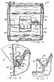
- FIGURE 5 is a front elevational view with a fragment broken away to illustrate details of the disengageable interlocking means;
- FIGURE 6 is an enlarged fragmentary section taken along the line 6-6 of Fig. 5 showing in solid lines details of the disengageable interlocking means and showing in phantom lines a position to which the upper seat section can be pivoted when disengaging the upper seat section from the lower holding tank section;
- FIGURE 7 is an enlarged fragmentary section taken along the line 7-7 of Fig. 5 showing details of the disengageable interlocking means;
- FIGURE 8 is a rear elevational view showing in solid lines the position of the handle of the clasp means in its secured position and showing in broken lines its position when in a disengaged position;
- FIGURE 9 is an enlarged fragmentary section taken along the line 9-9 of Fig. 2;
- FIGURE 10 is a vertical section taken along the line 10-10 of Fig. 1 showing details of the discharge spout and closure cap of the holding tank section and the cavity therefor in the seat section;
- FIGURE 11 is an enlarged fragmentary section taken along the line 11-11 of Fig. 1, showing details of the pump; and
- FIGURE 12 is an enlarged fragmentary section taken along the line 12-12 of Fig. 1, showing details of the valve-and-nozzle assembly of the flush means.
- Referring now to the drawings a
portable toilet 10 comprises a lowerholding tank section 12 and anupper seat section 14 removably supported thereon. Theupper seat section 14 is moulded of a suitable plastics material so as to have atop wall 16,side walls 18 and abottom wall 20 with anoutlet port 22 in the bottom wall defined by anannular flange 24. Theupper seat section 14 also includes abowl 26 extending between the top andbottom walls bottom wall 20. Thebowl 26 is open at the bottom through theoutlet port 22. Aflush water compartment 28 is provided in the space between thebowl 26 and within the confines of theside walls 18 and the top andbottom walls fill spout 30 is provided in the junction between therear side wall 18 and thetop wall 16 for filling flush water into theflush water compartment 28, and aclosure cap 32 is provided for closing thespout 30. Ahandle 34 is moulded in therear side wall 18 for carrying theupper seat section 14. - The
upper seat section 14 contains flush means 36 which includes a valve-and-nozzle assembly 38, apump 40 and aflexible conduit 42. A more detailed description of the flush means 36 will follow hereinafter. - Also forming a part of the
upper seat section 14 is atoilet seat 44 and acover 46, both of which are pivotally mounted at 48 in a conventional manner. - The lower
holding tank section 12 has atop wall 50,side walls 52 and abottom wall 54 forming a closed receptacle with aninlet port 56 in its top wall in registry with theoutlet port 22 of theupper seat section 14. Aslide valve assembly 58 is mounted on theholding tank section 12 and includes a flat blade orvalve element 60 which is supported within the confines of the holding tank section for movement in a horizontal plane perpendicular to the axis of theinlet port 56 for closing the inlet port and sealing the interior of theholding tank section 12 from the environment. A slide valve assembly such as is shown in the specification of United States Patent No. 3,949,430 may be used. - Briefly, the
slide valve assembly 58 includes ahandle 62 to which the blade orvalve element 60 is attached, and the handle extends through an opening in thefront side wall 52 in a sealed relationship provided by theannular seal 64. Because the handle extends into the interior of theholding tank 12, aprotective bellows 66 is fitted over the shaft of thehandle 62 and is secured in sealed relationship with theannular seal 64. - The
flat blade 60 is supported between guide surfaces for movement between the closed position shown in Fig. 2 and the open position shown in Fig. 10. The apparatus forming the inlet port in thetop wall 50 includes anannular seal ring 68 which aids in defining theinlet port 56 and which includes alip 70 into which theannular flange 24 is pressed when securing theupper seat section 14 onto the lowerholding tank section 12. Theannular seal ring 68 has a lower lip 72 which is in wiping relationship with the top surface of theblade 60. - The
blade 60 also has anoffset portion 74 which defines a closure element for cooperation with avent port 76 that is located in thetop wall 50. Thevent port 76 includes a port hole (not shown) and anelastomeric seal 78 associated therewith. Theoffset portion 74 and theseal 78 cooperate to provide desirable venting action for theholding tank 12 during operations when thevalve assembly 58 is being opened and closed. This vent apparatus is illustrated and described in greater detail in United States Patent Specification No. 4,145,773. - The lower
holding tank section 12 has ahandle 80 in therear side wall 52 for carrying purposes. - Disengageable interlocking means 82 and releasable clasp means 84 are employed for securihg the
upper seat section 14 onto the lowerholding tank section 12. The disengageable interlocking means 82 are integrally moulded into the top and bottom walls respectively of the lowerholding tank section 12 and theupper seat section 14, as can be seen best in Fig. 6. As there shown, thebottom wall 20 of theupper seat section 14 has aleg 86 which extends into thesocket 88 in thetop wall 50 of theholding tank 12 so that theupper seat section 14 can move relative to theholding tank 12 about anaxis 90 from the solid line position to the position of the seat section shown in phantom lines in Fig. 6. Thus theleg 86 and thesocket 88 form hinge-like elements located in the top andbottom walls hinge axis 90 for pivotal movement of theseat section 14 relative to theholding tank section 12. Theupper wall 92 of the socket is reinforced by aflange 94 and a plurality ofdrainage holes 96 prevent accumulation of moisture in the pockets behind thetop wall 92 of thesockets 88. As best seen in Fig. 4, a plurality of spacedsockets 88 are located in the top wall of theholding tank 12 adjacent to thefront side wall 52, and a plurality oflegs 86 are located at similar positions adjacent to thefront side wall 18 of theupper seat section 14 for fitting into these sockets. - The releasable clasp means 84 are located at the top and bottom walls respectively of the
hold tank section 12 and theseat section 14 adjacent to therear side walls strap 96 which has a pair ofslots 98 therein is secured by fastening means 100 for transverse sliding movement relative to thebottom wall 20 of theupper seat section 14. This movement can be imparted to thestrap 96 by means of ahandle 102 that is connected thereto. Thestrap 96 also has akeyhole slot 104 with anenlarged opening 106. Secured to the lowerholding tank section 12 is aretention member 108 that has anenlarged head 110 which can fit through theopening 106 in theslot 104, and when thestrap 96 is moved transversely theenlarged head 110 will be locked in place relative to the narrower portion of theslot 104. During the movement of the strap from the position wherein thehead 110 is in theopening 106 to . the other end ofslot 104, theenlarged head 110 will be caused to move on theramp 112, Fig. 9, and this will cause the two sections to be pulled tightly together to the position shown in Fig. 9. During this locking action, the pivotal movement that occurs will be about theaxis 90, Fig. 6, so that a relatively long lever arm from theaxis 90 to theenlarged head 110 will be provided. Not only does this serve to bring the twosections annular flange 24 and the sealingring 68 where theoutlet port 22 of the bowl and theinlet port 56 of theholding tank section 12 comes into registry. The leverage that is provided will assure that theflange 24 is moved completely into sealed relationship with thelip 70. - Another advantageous feature of the present construction is the location of the
discharge spout 114 for the holdingtank 12 in thetop wall 50 thereof. As seen best in Fig. 10, thedischarge spout 114 is located well above thevalve assembly 58 so that even when theholding tank section 12 is filled to capacity, the outlet end of thespout 114 is well above the liquid level. This serves to eliminate leakage problems that otherwise may occur at the spout if a good seal is not provided between theclosure cap 116 and thespout 114. This location also is convenient for the operator of the portable toilet when it is desired to add chemical concentrates or the like into the holdingtank 12. As can be seen, it is only necessary to release the clamping means 84 and then to pivot theupper seat section 14 to the position shown in phantom lines in Fig. 6, and while supporting the upper seat section in this position, thecap 116 can be removed and desired chemical compositions can be inserted into the holding tank. This feature also has desirable attributes in that thedischarge spout 114 and theclosure cap 116 are concealed so that theportable toilet 10 has a more aesthetically attractive appearance. In the preferred form of the invention the axis of thespout 114 is inclined substantially 45° to the horizontal, and it is directed to the rear of the holding tank. To accommodate this arrangement of thespout 114 andclosure cap 116, acavity 118 is formed in thebottom wall 20 of theseat section 14. - Still another preferred feature is the construction and arrangement of the flush means 36. A
conventional pump 40 with abellows 120 is provided which has a suction orinlet port 122, normally closed by a ball check-valve element 124. When the hand bellows is depressed, air/water therein will be urged out of the pump via thedischarge port 126 which constitutes the end of theflexible conduit 42, and theball checkvalve element 124 will then be urged into theport 122. During the return stroke of the bellows, theball check element 124 will be raised from its seat due to pressure drop in the bellows chamber, and the water will be drawn from thewater storage chamber 28 into the pump chamber. When the bellows is again depressed, the new charge of water will be discharged through theflexible conduit 42 and via the nozzle-and-valve assembly 38 into the bowl of thetoilet 10. As will be understood, it is necessary to have a check-valve either at thepump 120 or somewhere in theflexible conduit 42 to allow the pump to operate satisfactorily so that it can draw water through theinlet port 122. In the present embodiment of the invention, the check-valve on the discharge side of the pump is formed within the nozzle-and-valve assembly 38. - As shown in Fig. 12, the nozzle-and-
valve assembly 38 includes aunitary valve body 128 that defines at its outlet end anozzle 130 and at its inlet end avalve chamber 132. Theflexible conduit 42 has asocket 134 that is outwardly flared at 136, and thebody member 128 has anelastomeric annulus 138 mounted on its end to provide asleeve 140 around the outer side of the chamber and avalve seat 142 around the inner side of the chamber. Theannulus 138 is fitted into thesocket 134 to provide a sealed joint between the outer side of thechamber 132 and the inner side of the socket. Theelastomeric annulus 38 and thebody member 128 have interlocking means at 144 so that they can be press-fitted together and will be retained together as a unitary structure. - A check-
valve 146, comprising acompression spring 148 and avalve element 150, is provided. Thevalve element 150 is urged by thespring 148 into a closed seated position with respect to thevalve seat 142. Thevalve element 150 is adapted to be moved off theseat 142 in response to the pressure of the liquid discharged by thepump 40. The arrangement shown serves to prevent water retained within theflexible conduit 42 from being inadvertently spilled or discharged when theportable toilet 10 is being carried. Another feature of the valve-and-nozzle assembly 38 is acollar 152 which is seated against the inner walls of thebowl 26 and is secured in place by means of detent means 154, Fig. 2. It is to be observed that all of the components of the flush means 36 can be press-fitted together during the assembly operation and can be installed in the walls of theupper section 14. These press fit connectins are present at both ends of theflexible conduit 42 as well as with respect to the other components of the flush means 36.
Claims (16)
Applications Claiming Priority (2)
| Application Number | Priority Date | Filing Date | Title |
|---|---|---|---|
| US05/957,799 US4180876A (en) | 1978-11-06 | 1978-11-06 | Portable toilets |
| US957799 | 1978-11-06 |
Publications (3)
| Publication Number | Publication Date |
|---|---|
| EP0010962A1 EP0010962A1 (en) | 1980-05-14 |
| EP0010962B1 true EP0010962B1 (en) | 1983-01-19 |
| EP0010962B2 EP0010962B2 (en) | 1989-10-18 |
Family
ID=25500155
Family Applications (1)
| Application Number | Title | Priority Date | Filing Date |
|---|---|---|---|
| EP79302393A Expired EP0010962B2 (en) | 1978-11-06 | 1979-10-31 | Improvements in portable toilets |
Country Status (12)
| Country | Link |
|---|---|
| US (1) | US4180876A (en) |
| EP (1) | EP0010962B2 (en) |
| JP (1) | JPS5566335A (en) |
| AR (1) | AR221109A1 (en) |
| AU (1) | AU525850B2 (en) |
| BR (1) | BR7907169A (en) |
| CA (1) | CA1094254A (en) |
| DE (1) | DE2964556D1 (en) |
| ES (2) | ES253514Y (en) |
| IT (1) | IT1162410B (en) |
| MX (1) | MX149756A (en) |
| NZ (1) | NZ191623A (en) |
Families Citing this family (20)
| Publication number | Priority date | Publication date | Assignee | Title |
|---|---|---|---|---|
| USD262050S (en) | 1979-09-10 | 1981-11-24 | Thetford Corporation | Portable toilet |
| US4215445A (en) * | 1979-09-14 | 1980-08-05 | Thetford Corporation | Portable toilets |
| US4217668A (en) * | 1979-09-20 | 1980-08-19 | Thetford Corporation | Portable toilet |
| US4439875A (en) * | 1981-06-02 | 1984-04-03 | Sanitation Equipment Limited | Toilet |
| EP0095903B2 (en) * | 1982-06-01 | 1993-06-23 | Thetford Corporation | Portable toilet having a holding tank spout |
| US4776631A (en) * | 1986-06-05 | 1988-10-11 | Thetford Corporation | Self-contained RV sanitary systems |
| US4850064A (en) * | 1987-11-09 | 1989-07-25 | Thetford Corporation | Portable toilet with vent for flush water supply tank |
| US4982456A (en) * | 1987-11-09 | 1991-01-08 | Thetford Corporation | Portable toilet with vent for flush water supply tank |
| US5031249A (en) * | 1989-06-23 | 1991-07-16 | Thetford Corporation | Universal recreational vehicle toilet system with removable holding tank |
| CA1315491C (en) * | 1989-06-28 | 1993-04-06 | Desmond Maurice Kendall | Sanitary fixtures |
| DE9201682U1 (en) * | 1991-06-04 | 1992-06-11 | kki Handelsgesellschaft für Kunststofferzeugnisse mbH, 1000 Berlin | Toilet arrangement for installation without fixed disposal connection |
| GB2271127B (en) * | 1992-09-30 | 1996-07-31 | Emlyn Robert Miller | Apparatus and method for connecting a portable toilet to a waste/sewage disposal system |
| AUPM320293A0 (en) * | 1993-12-31 | 1994-01-27 | Merlin Services Pty Ltd | Mobile toilet |
| US5513395A (en) * | 1994-08-23 | 1996-05-07 | Thetford Corporation | Toilet with magnetic check valve |
| US5557810A (en) * | 1994-08-24 | 1996-09-24 | Thetford Corporation | Portable toilet with battery operated flush assembly |
| US20070044222A1 (en) * | 2005-08-24 | 2007-03-01 | Hedberg Margaret | Portable sanitary device |
| US7765625B2 (en) | 2006-02-17 | 2010-08-03 | Thetford Corporation | Flush toilet assembly |
| WO2008064416A1 (en) * | 2006-11-28 | 2008-06-05 | Oakmoore Pty Ltd | Portable toilet or restroom structures |
| CN108036085B (en) * | 2017-12-20 | 2023-12-01 | 苏州大学 | Check valve for highly viscous fluids |
| CN219863160U (en) * | 2023-03-15 | 2023-10-20 | 青岛矢车菊设计有限公司 | portable toilet |
Family Cites Families (10)
| Publication number | Priority date | Publication date | Assignee | Title |
|---|---|---|---|---|
| US3570018A (en) * | 1968-04-25 | 1971-03-16 | Thetford Corp | Portable toilet |
| BE790564A (en) * | 1971-10-27 | 1973-02-15 | Thetford Corp | PORTABLE TOILET |
| US3772711A (en) * | 1972-04-03 | 1973-11-20 | S Spector | Toilet with disposable receptacle |
| JPS4923031A (en) * | 1972-06-13 | 1974-03-01 | ||
| US3801991A (en) * | 1972-11-29 | 1974-04-09 | Mansfield Sanitary Inc | Portable, self-contained toilet |
| US3851339A (en) * | 1973-10-23 | 1974-12-03 | Mansfield Sanitary Inc | Portable, self-contained toilet |
| US3949430A (en) * | 1975-01-20 | 1976-04-13 | Thetford Corporation | Portable toilet |
| US4032996A (en) * | 1976-08-04 | 1977-07-05 | Thetford Corporation | Sealing apparatus for toilet |
| US4091475A (en) * | 1976-11-04 | 1978-05-30 | Sanitation Equipment Limited | Portable toilets |
| US4145773A (en) * | 1978-04-03 | 1979-03-27 | Thetford Corporation | Portable toilet with vent means for the holding tank |
-
1978
- 1978-11-06 US US05/957,799 patent/US4180876A/en not_active Expired - Lifetime
-
1979
- 1979-09-20 AU AU51000/79A patent/AU525850B2/en not_active Ceased
- 1979-09-20 NZ NZ191623A patent/NZ191623A/en unknown
- 1979-09-24 AR AR278176A patent/AR221109A1/en active
- 1979-10-17 MX MX179668A patent/MX149756A/en unknown
- 1979-10-31 DE DE7979302393T patent/DE2964556D1/en not_active Expired
- 1979-10-31 EP EP79302393A patent/EP0010962B2/en not_active Expired
- 1979-11-05 ES ES1979253514U patent/ES253514Y/en not_active Expired
- 1979-11-05 JP JP14317779A patent/JPS5566335A/en active Granted
- 1979-11-05 BR BR7907169A patent/BR7907169A/en not_active IP Right Cessation
- 1979-11-05 ES ES1979253513U patent/ES253513Y/en not_active Expired
- 1979-11-05 IT IT50735/79A patent/IT1162410B/en active
- 1979-11-06 CA CA339,224A patent/CA1094254A/en not_active Expired
Also Published As
| Publication number | Publication date |
|---|---|
| US4180876A (en) | 1980-01-01 |
| EP0010962B2 (en) | 1989-10-18 |
| ES253513U (en) | 1980-12-16 |
| NZ191623A (en) | 1983-05-10 |
| AU525850B2 (en) | 1982-12-02 |
| CA1094254A (en) | 1981-01-27 |
| JPS5566335A (en) | 1980-05-19 |
| EP0010962A1 (en) | 1980-05-14 |
| IT1162410B (en) | 1987-04-01 |
| ES253513Y (en) | 1981-06-01 |
| IT7950735A0 (en) | 1979-11-05 |
| AR221109A1 (en) | 1980-12-30 |
| JPH0226962B2 (en) | 1990-06-13 |
| ES253514U (en) | 1980-12-16 |
| MX149756A (en) | 1983-12-15 |
| ES253514Y (en) | 1981-06-01 |
| AU5100079A (en) | 1980-05-15 |
| BR7907169A (en) | 1980-06-17 |
| DE2964556D1 (en) | 1983-02-24 |
Similar Documents
| Publication | Publication Date | Title |
|---|---|---|
| EP0010962B1 (en) | Improvements in portable toilets | |
| US4776631A (en) | Self-contained RV sanitary systems | |
| US5190190A (en) | Moldable two-part valve body | |
| US6138322A (en) | Upright carpet and upholstery extractor | |
| US4830229A (en) | Pump chamber dispenser | |
| US4573612A (en) | Liquid soap dispenser | |
| US3949430A (en) | Portable toilet | |
| US3570018A (en) | Portable toilet | |
| US4217668A (en) | Portable toilet | |
| US4091475A (en) | Portable toilets | |
| JPH05501840A (en) | valve mechanism | |
| US4944048A (en) | Self-contained RV sanitary system | |
| KR100470132B1 (en) | Pressure flush device | |
| JPH0430974Y2 (en) | ||
| US20250230029A1 (en) | Backup valve for closed transfer coupler | |
| CA1158403A (en) | Toilet | |
| US5056166A (en) | Self-contained RV sanitary systems | |
| US20060138168A1 (en) | System for supplying a substance | |
| US4924908A (en) | Apparatus for withdrawing liquid from a reservoir by means of a water jet device | |
| EP0257927A2 (en) | Portable toilet with valve actuating handle that automatically locks the valve in closed position during emptying of the holding tank | |
| WO1994017722A1 (en) | Appliances for cleaning or otherwise treating floor and other surfaces | |
| JPH075791Y2 (en) | Liquid container | |
| WO1994027486A1 (en) | An arrangement for emptying a liquid receiving container | |
| JPH0646444Y2 (en) | Pump injection type liquid container | |
| JPH058934Y2 (en) |
Legal Events
| Date | Code | Title | Description |
|---|---|---|---|
| PUAI | Public reference made under article 153(3) epc to a published international application that has entered the european phase |
Free format text: ORIGINAL CODE: 0009012 |
|
| AK | Designated contracting states |
Designated state(s): BE DE FR GB NL SE |
|
| 17P | Request for examination filed | ||
| GRAA | (expected) grant |
Free format text: ORIGINAL CODE: 0009210 |
|
| AK | Designated contracting states |
Designated state(s): BE DE FR GB NL SE |
|
| PG25 | Lapsed in a contracting state [announced via postgrant information from national office to epo] |
Ref country code: SE Effective date: 19830119 Ref country code: NL Effective date: 19830119 Ref country code: BE Effective date: 19830119 |
|
| REF | Corresponds to: |
Ref document number: 2964556 Country of ref document: DE Date of ref document: 19830224 |
|
| ET | Fr: translation filed | ||
| PLBI | Opposition filed |
Free format text: ORIGINAL CODE: 0009260 |
|
| NLV1 | Nl: lapsed or annulled due to failure to fulfill the requirements of art. 29p and 29m of the patents act | ||
| 26 | Opposition filed |
Opponent name: SANITATION EQUIPMENT LTD. Effective date: 19830525 |
|
| PLBI | Opposition filed |
Free format text: ORIGINAL CODE: 0009260 |
|
| PLAB | Opposition data, opponent's data or that of the opponent's representative modified |
Free format text: ORIGINAL CODE: 0009299OPPO |
|
| 26 | Opposition filed |
Opponent name: FIAMMA S.P.A. Effective date: 19830928 |
|
| R26 | Opposition filed (corrected) |
Opponent name: SANITATION EQUIPMENT LTD. * 830928 FIAMMA S.P.A. Effective date: 19830525 |
|
| PUAH | Patent maintained in amended form |
Free format text: ORIGINAL CODE: 0009272 |
|
| STAA | Information on the status of an ep patent application or granted ep patent |
Free format text: STATUS: PATENT MAINTAINED AS AMENDED |
|
| 27A | Patent maintained in amended form |
Effective date: 19891018 |
|
| AK | Designated contracting states |
Kind code of ref document: B2 Designated state(s): BE DE FR GB NL SE |
|
| ET3 | Fr: translation filed ** decision concerning opposition | ||
| PGFP | Annual fee paid to national office [announced via postgrant information from national office to epo] |
Ref country code: FR Payment date: 19960913 Year of fee payment: 18 |
|
| PGFP | Annual fee paid to national office [announced via postgrant information from national office to epo] |
Ref country code: DE Payment date: 19960917 Year of fee payment: 18 |
|
| PGFP | Annual fee paid to national office [announced via postgrant information from national office to epo] |
Ref country code: GB Payment date: 19960925 Year of fee payment: 18 |
|
| PG25 | Lapsed in a contracting state [announced via postgrant information from national office to epo] |
Ref country code: GB Free format text: LAPSE BECAUSE OF NON-PAYMENT OF DUE FEES Effective date: 19971031 Ref country code: FR Free format text: THE PATENT HAS BEEN ANNULLED BY A DECISION OF A NATIONAL AUTHORITY Effective date: 19971031 |
|
| GBPC | Gb: european patent ceased through non-payment of renewal fee |
Effective date: 19971031 |
|
| PG25 | Lapsed in a contracting state [announced via postgrant information from national office to epo] |
Ref country code: DE Free format text: LAPSE BECAUSE OF NON-PAYMENT OF DUE FEES Effective date: 19980701 |
|
| REG | Reference to a national code |
Ref country code: FR Ref legal event code: ST |