EP3922166B1 - Display device, display method and display program - Google Patents
Display device, display method and display program Download PDFInfo
- Publication number
- EP3922166B1 EP3922166B1 EP19918516.6A EP19918516A EP3922166B1 EP 3922166 B1 EP3922166 B1 EP 3922166B1 EP 19918516 A EP19918516 A EP 19918516A EP 3922166 B1 EP3922166 B1 EP 3922166B1
- Authority
- EP
- European Patent Office
- Prior art keywords
- index
- gaze point
- display
- subject
- unit
- Prior art date
- Legal status (The legal status is an assumption and is not a legal conclusion. Google has not performed a legal analysis and makes no representation as to the accuracy of the status listed.)
- Active
Links
- 238000000034 method Methods 0.000 title claims description 58
- 238000001514 detection method Methods 0.000 claims description 35
- 230000008569 process Effects 0.000 claims description 30
- 238000010586 diagram Methods 0.000 description 19
- 230000000007 visual effect Effects 0.000 description 16
- 210000001508 eye Anatomy 0.000 description 15
- 238000011156 evaluation Methods 0.000 description 13
- 238000003384 imaging method Methods 0.000 description 12
- 238000005070 sampling Methods 0.000 description 9
- 210000005252 bulbus oculi Anatomy 0.000 description 6
- 238000012545 processing Methods 0.000 description 6
- 230000006870 function Effects 0.000 description 5
- 230000001360 synchronised effect Effects 0.000 description 5
- 238000005516 engineering process Methods 0.000 description 4
- 208000029560 autism spectrum disease Diseases 0.000 description 3
- 210000001747 pupil Anatomy 0.000 description 3
- 238000004458 analytical method Methods 0.000 description 2
- 230000001149 cognitive effect Effects 0.000 description 2
- 238000004590 computer program Methods 0.000 description 2
- 238000003745 diagnosis Methods 0.000 description 2
- 238000012544 monitoring process Methods 0.000 description 2
- 230000004044 response Effects 0.000 description 2
- 238000012216 screening Methods 0.000 description 2
- 230000015572 biosynthetic process Effects 0.000 description 1
- 230000003920 cognitive function Effects 0.000 description 1
- 239000003086 colorant Substances 0.000 description 1
- 238000004891 communication Methods 0.000 description 1
- 238000013480 data collection Methods 0.000 description 1
- 230000001419 dependent effect Effects 0.000 description 1
- 230000000694 effects Effects 0.000 description 1
- 238000005401 electroluminescence Methods 0.000 description 1
- 230000004424 eye movement Effects 0.000 description 1
- 230000010365 information processing Effects 0.000 description 1
- 230000003993 interaction Effects 0.000 description 1
- 239000004973 liquid crystal related substance Substances 0.000 description 1
- 230000003287 optical effect Effects 0.000 description 1
- 238000007639 printing Methods 0.000 description 1
- 238000012956 testing procedure Methods 0.000 description 1
- 230000002747 voluntary effect Effects 0.000 description 1
Images


Classifications
-
- A—HUMAN NECESSITIES
- A61—MEDICAL OR VETERINARY SCIENCE; HYGIENE
- A61B—DIAGNOSIS; SURGERY; IDENTIFICATION
- A61B3/00—Apparatus for testing the eyes; Instruments for examining the eyes
- A61B3/0091—Fixation targets for viewing direction
-
- A—HUMAN NECESSITIES
- A61—MEDICAL OR VETERINARY SCIENCE; HYGIENE
- A61B—DIAGNOSIS; SURGERY; IDENTIFICATION
- A61B3/00—Apparatus for testing the eyes; Instruments for examining the eyes
- A61B3/0016—Operational features thereof
- A61B3/0041—Operational features thereof characterised by display arrangements
-
- A—HUMAN NECESSITIES
- A61—MEDICAL OR VETERINARY SCIENCE; HYGIENE
- A61B—DIAGNOSIS; SURGERY; IDENTIFICATION
- A61B3/00—Apparatus for testing the eyes; Instruments for examining the eyes
- A61B3/10—Objective types, i.e. instruments for examining the eyes independent of the patients' perceptions or reactions
- A61B3/113—Objective types, i.e. instruments for examining the eyes independent of the patients' perceptions or reactions for determining or recording eye movement
Definitions
- the present disclosure relates to a display apparatus, a display method, and a display program.
- Visual cognitive functions include a function to input information from eyes and a function to recognize the input information.
- visual performance such as eye movement, for looking at a target object is important.
- a method of evaluating the visual performance for example, a technology for displaying a graphic on a display unit, requesting a subject to gaze at the graphic, detecting a position of a gaze point, and calculating a gaze time in a predetermined region of the graphic has been disclosed (for example, see JP 2017-158868 A ).
- WO 2017 213 070 A discloses an information processing device and method and a recording medium which controls a display device disposed along a prescribed direction within the visual field of a user, the display device being controlled so as to display a stereoscopic object that indicates distance pertaining to the prescribed direction.
- WO 2017 031 089 A discloses systems and methods for discerning the intent of a device wearer primarily based on movements of the eyes.
- the system may be included within unobtrusive headwear that performs eye tracking and controls screen display.
- the system may also utilize remote eye tracking camera(s), remote displays and/or other ancillary inputs.
- Screen layout is optimized to facilitate the formation and reliable detection of rapid eye signals.
- the detection of eye signals is based on tracking physiological movements of the eye that are under voluntary control by the device wearer.
- the detection of eye signals results in actions that are compatible with wearable computing and a wide range of display devices.
- US 2014 253 876 A discloses systems, devices, and methods for the assessment, screening, monitoring, or diagnosis of developmental or cognitive conditions, including autism spectrum disorders (ASD) by analysis of eye tracking data generated from feedback received as a result of display of specific predetermined visual stimuli to a subject or patient.
- ASD autism spectrum disorders
- a testing procedure is performed by presenting predetermined stimuli (e.g., videos) to a subject via a display device.
- Eye tracking data (from the subject moving his or her eyes in response to predetermined movies or other visual stimuli) are collected.
- the system periodically presents targets to reflexively elicit the subject's gaze. These data are used to later verify accuracy. Analysis of the subject's viewing patterns during these stimuli is used for the assessment, screening, monitoring, or diagnosis of developmental or cognitive conditions such as ASD.
- US 2016 209 917 A discloses a method to provide visual feedback for gazed-based user-interface navigation includes presenting, on a display, a first image representing a digital object available for user interaction, recognizing a user gaze axis, and computing a point of intersection of the user gaze axis through the first image. An offset distance between the point of intersection and a reference position of the first image then recognized, and a second image is presented on the display. The second image is presented displaced from the point of intersection by an amount dependent on the offset distance.
- US 2019 073024 A discloses a gaze detection device which includes a display screen configured to display an image; a sound output device configured to output a sound; a gaze point detector configured to detect a position of a point of gaze of an observer observing the display screen; an area setting unit configured to set a specific area on the display screen or part of the image; a determination unit configured to, when the specific area is set on the display screen or the image, determine whether the point of gaze is within the specific area on the basis of a result of the detecting the position of the point of gaze; and an output controller configured to cause the display screen to display the image and cause the sound output device to output the sound and adjust at least a mode in which the sound is output.
- JP 2017-158868 A a technology for detecting the gaze point of the subject, calculating the gaze time, and performing evaluation by an evaluator is described.
- JP 2017-158868 A while evaluation of the visual performance of the subject is described, feedback on a state of the visual performance to the subject is not described.
- the present disclosure has been conceived in view of the foregoing situation, and an object of the present disclosure is to provide a display apparatus, a display method, and a display program capable of giving feedback on a state of visual performance to a subject.
- a display apparatus according to the present disclosure comprises the features of claim 1.
- a display method according to the present disclosure comprises the steps of claim 4.
- a display program according to the present disclosure is defined by the features of claim 5.
- a display apparatus capable of giving feedback on a state of visual performance to a subject.
- Embodiments of a display apparatus, a display method, and a display program according to the present disclosure will be described below based on the drawings. The disclosure is not limited by the embodiments below. In addition, structural elements in the embodiments described below include one that can easily be thought of by a person skilled in the art and one that is practically identical.
- the three-dimensional global coordinate system is set to describe positional relationships between components.
- a direction parallel to a first axis of a predetermined plane will be referred to as an X-axis direction
- a direction parallel to a second axis of the predetermined plane perpendicular to the first axis will be referred to as an Y-axis direction
- a direction parallel to a third axis perpendicular to each of the first axis and the second axis will be referred to as a Z-axis direction.
- the predetermined plane includes an XY plane.
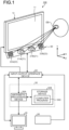
- FIG. 1 is a diagram schematically illustrating an example of a display apparatus 100 according to the present embodiment.
- the display apparatus 100 detects a line of sight of a subject, and gives feedback on a state of visual performance to the subject by using a detection result.
- various apparatuses capable of detecting a line of sight of a subject such as an apparatus that detects the line of sight on the basis of a position of a pupil of the subject and a position of a corneal reflection image and an apparatus that detects the line of sight on the basis of a position of an inner corner of an eye of the subject and a position of an iris of the subject, may be used, for example.
- the display apparatus 100 includes a display device 10, an image acquisition device 20, a computer system 30, an output device 40, an input device 50, and an input-output interface device 60.
- the display device 10, the image acquisition device 20, the computer system 30, the output device 40, and the input device 50 perform data communication via the input-output interface device 60.
- Each of the display device 10 and the image acquisition device 20 includes a driving circuit (not illustrated).
- the display device 10 includes a flat panel display, such as a liquid crystal display (LCD) or an organic electroluminescence display (OLED).
- the display device 10 includes a display unit 11.
- the display unit 11 displays information, such as an image.
- the display unit 11 is substantially parallel to the XY plane.
- the X-axis direction is a horizontal direction of the display unit 11
- the Y-axis direction is a vertical direction of the display unit 11
- the Z-axis direction is a depth direction perpendicular to the display unit 11.
- the display device 10 may be a head mounted display device. If the display device 10 is a head mounted display device, a component like the image acquisition device 20 is arranged in a head mounted module.
- the image acquisition device 20 acquires image data of left and right eyeballs EB of the subject, and transmits the acquired image data to the computer system 30.
- the image acquisition device 20 includes an imaging device 21.
- the imaging device 21 captures images of the left and right eyeballs EB of the subject and acquires image data.
- the imaging device 21 includes various cameras corresponding to methods of detecting the line of sight of the subject. For example, if a method of detecting the line of sight based on a position of a pupil of the subject and a position of a corneal reflection image is adopted, the imaging device 21 includes an infrared camera, an optical system capable of transmitting near-infrared light at a wavelength of 850 nm, and an imaging element capable of receiving the near-infrared light, for example.
- the imaging device 21 includes a visible light camera.
- the imaging device 21 outputs a frame synchronous signal.
- a cycle of the frame synchronous signal may be, for example, 20 milliseconds (msec), but is not limited thereto.
- the imaging device 21 may be configured as, for example, a stereo camera including a first camera 21A and a second camera 21B, but is not limited thereto.
- the image acquisition device 20 includes a lighting device 22 that illuminates the eyeballs EB of the subject.
- the lighting device 22 includes a light emitting diode (LED) light source, for example, and is able to emit near-infrared light at a wavelength of 850 nm.
- LED light emitting diode
- the lighting device 22 may be omitted.
- the lighting device 22 emits detection light in synchronization with the frame synchronous signal of the imaging device 21.
- the lighting device 22 may include, for example, a first light source 22A and a second light source 22B, but is not limited thereto.
- the computer system 30 integrally controls operation of the display apparatus 100.
- the computer system 30 includes an arithmetic processing device 30A and a storage device 30B.
- the arithmetic processing device 30A includes a microprocessor, such as a central processing unit (CPU).
- the storage device 30B includes a memory, such as a read only memory (ROM) and a random access memory (RAM), or a storage.
- the arithmetic processing device 30A performs an arithmetic process in accordance with a computer program 30C that is stored in the storage device 30B.
- the output device 40 includes a display device, such as a flat panel display. Meanwhile, the output device 40 may include a printing device.
- the input device 50 generates input data by being operated.
- the input device 50 includes a keyboard or a mouse for a computer system. Meanwhile, the input device 50 may include a touch sensor that is arranged on a display unit of the output device 40 that is a display device.
- the display device 10 and the computer system 30 are separate devices. Meanwhile, the display device 10 and the computer system 30 may be integrated.
- the display apparatus 100 may include a tablet personal computer.
- the display device, the image acquisition device, the computer system, the input device, the output device, and the like may be mounted on the tablet personal computer.
- FIG. 2 is a functional block diagram illustrating an example of the display apparatus 100.
- the computer system 30 includes a display control unit 31, a gaze point detection unit 32, a region setting unit 33, a determination unit 34, an arithmetic unit 35, an evaluation unit 36, an input-output control unit 37, and a storage unit 38.
- Functions of the computer system 30 are implemented by the arithmetic processing device 30A and the storage device 30B (see FIG. 1 ). Meanwhile, a part of the functions of the computer system 30 may be arranged outside the display apparatus 100.
- the gaze point detection unit 32 detects positional data of a gaze point of the subject.
- the gaze point detection unit 32 detects a line-of-sight vector of the subject defined by the three-dimensional global coordinate system, on the basis of the image data of the left and right eyeballs EB of the subject acquired by the image acquisition device 20.
- the gaze point detection unit 32 detects positional data of an intersection of the detected line-of-sight vector of the subject and the display unit 11 of the display device 10, as the positional data of the gaze point of the subject.
- the positional data of the gaze point is the positional data of the intersection of the line-of-sight vector of the subject and the display unit 11 of the display device 10 defined by the three-dimensional global coordinate system.
- the gaze point is a designated point that is designated on the display unit 11 by being gazed at by the subject.
- the gaze point detection unit 32 detects the positional data of the gaze point of the subject for each prescribed sampling cycle.
- the sampling cycle may be, for example, the cycle (for example, every 20 msec) of the frame synchronous signal output from the imaging device 21.
- the region setting unit 33 sets specific regions in the display unit 11.
- the specific regions may have various planner shapes, such as circles, ellipses, polygons, or combinational shapes of circles, ellipses, and polygons, for example.
- the region setting unit 33 may set the specific regions in the entire display unit 11 or may set the specific regions in a part of the display unit 11. In the present embodiment, each of the regions set by the region setting unit 33 is not displayed on the display unit 11 in principle. Meanwhile, each of the regions may be displayed on the display unit 11 under the control of the display control unit 31, for example.
- the determination unit 34 determines whether the gaze point is present in a specific region in a period in which the region setting unit 33 sets the specific region, and outputs determination data.
- the determination unit 34 determines whether the gaze point is present in the specific region for each prescribed determination cycle.
- the determination cycle may be, for example, the same cycle as the cycle (for example, every 20 msec) of the frame synchronous signal output from the imaging device 21. In this case, the determination cycle of the determination unit 34 is the same as the sampling cycle of the gaze point detection unit 32.
- the arithmetic unit 35 calculates gaze point data that indicates a course of movement of the gaze point in the period in which the specific region is set as described above, on the basis of the determination data of the determination unit 34.
- the arithmetic unit 35 calculates presence time data as the gaze point data, for example.
- the presence time data is data that indicates presence time in which the gaze point is present in the specific region. It is possible to estimate that the presence time in which the gaze point is present in the specific region increases with an increase in the number of times that the determination unit 34 determines that the gaze point is present in the specific region. Therefore, in the present embodiment, it is assumed that the presence time is the number of times of determination made by the determination unit 34. In other words, it is assumed that the presence time is the number of samplings of gaze points detected in the specific region.
- the arithmetic unit 35 includes a counter that counts the number of times that the determination unit 34 determines that the gaze point is present in the specific region.
- the display control unit 31 displays an evaluation image for evaluating visual performance of the subject on the display unit 11.
- a display mode of the evaluation image may be any of a moving image and a still image.
- the display control unit 31 displays an index at a position corresponding to the gaze point on the display unit 11. In this case, if the presence time is equal to or larger than a predetermined time as the index display condition, the display control unit 31 displays the index on the display unit 11.
- the index includes, for example, a moving index and a fixed index.
- the moving index is displayed at the position of the gaze point every time the gaze point detection unit 32 detects the gaze point. In other words, the moving index is displayed at a position of a sampled gaze point every time the gaze point detection unit 32 performs sampling.
- the fixed index is displayed at the position of the gaze point at the time the gaze point data meets the index display condition. In other words, the fixed index is displayed at a position of a gaze point that meets the index display condition.
- the index may have various shapes, such as a circle, an ellipse, a polygon, or a combinational shape of a circle, an ellipse, and a polygon, for example. Further, the shape of the index is not limited to a geometric shape, and may be an image representing an animal, a plant, or the like.
- the index may have any color as long as the color is displayable on the display unit 11, and may have a single color or a mixed color of a plurality of colors, for example.
- the index may have any size as long as the size is displayable on the display unit 11, for example.
- the display control unit 31 hides the index if the gaze point data does not meet the index display condition while the index is being displayed on the display unit 11.
- the index as described above is stored, as index data, in the storage unit 38.
- the evaluation unit 36 obtains evaluation data of the subject on the basis of the gaze point data.
- the evaluation data includes, for example, data for evaluating whether the subject is able to gaze at a predetermined region in the evaluation image displayed on the display unit 11.
- the input-output control unit 37 acquires data (the image data of the eyeballs EB, the input data, or the like) from at least one of the image acquisition device 20 and the input device 50. Further, the input-output control unit 37 outputs data to at least one of the display device 10 and the output device 40. The input-output control unit 37 may output a task for the subject from the output device 40, such as a speaker.
- the storage unit 38 stores therein the determination data, the gaze point data (the presence time data), and the index data as described above. Further, the storage unit 38 stores therein a display program that causes a computer to perform a process of detecting positions of gaze points of the subject who observes the display unit 11, a process of setting a specific region in the display unit 11, a process of determining whether each of the gaze points is present in the specific region, a process of calculating the gaze point data on the basis of a determination result, and a process of displaying an index at a position corresponding to the gaze point on the display unit 11 if the gaze point data meets the index display condition.
- a display method according to the present embodiment will be described below.
- feedback on a state of visual performance is given to the subject by using the display apparatus 100 as described above.
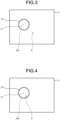
- FIG. 3 is a diagram illustrating an example of contents displayed on the display unit 11.
- the display control unit 31 displays the evaluation image for evaluating the visual performance of the subject on the display unit 11.
- the display control unit 31 displays, for example, a target object Q on the display unit 11.
- the target object Q has, for example, a circular shape. Meanwhile, it is possible to cause the display unit 11, the output device 40, or the like to give, in advance, an instruction to gaze at the target object Q for a while to the subject. Meanwhile, the target object Q need not always have a circular shape.
- the region setting unit 33 sets a specific region AR corresponding to the target object Q.
- the specific region AR is a circle centered at a reference position A. Meanwhile, the specific region AR need not always have a circular shape, but may have a different shape.
- the reference position A may be, for example, a center position of the target object Q.
- the region setting unit 33 is able to set the specific region AR in a region including the target object Q, for example.
- the gaze point detection unit 32 detects a position of a gaze point P of the subject on the display unit 11 for each prescribed sampling cycle (for example, 20 msec). While the position of the gaze point P detected by the gaze point detection unit 32 is represented by a dashed line on the display unit 11, the gaze point P is not displayed on the display unit 11 at the time as illustrated in FIG. 3 . If the gaze point P is not displayed as described above, it is difficult for the subject to recognize a position at which the subject is gazing at.
- a position that the subject recognizes as a gaze position and a position of the detected gaze point are different, it is difficult to recognize deviation between the gaze position recognized by the subject and the position of the detected gaze point, so that, in some cases, a result indicating a gaze at a position that is different from the position recognized by the subject may be obtained.
- the display control unit 31 displays an index at a position corresponding to the gaze point P on the display unit 11 if the gaze point data meets the index display condition.
- the determination unit 34 determines whether the gaze point P is present in the specific region AR in a period in which the region setting unit 33 sets the specific region AR, and outputs determination data.
- the determination unit 34 determines whether the gaze point P is present in the specific region AR for each prescribed determination cycle.
- the determination cycle is the same as the sampling cycle of the gaze point detection unit 32.
- the arithmetic unit 35 calculates the gaze point data that indicates a course of movement of the gaze point P in the period in which the specific region AR is set, on the basis of the determination data of the determination unit 34.
- the arithmetic unit 35 calculates the presence time data as the gaze point data, for example.
- the display control unit 31 displays the index at the position corresponding to the gaze point P on the display unit 11.
- a first presence time is equal to or larger than a predetermined time as a first index display condition (hereinafter, described as a "first condition")
- the display control unit 31 displays an index at the position corresponding to the gaze point on the display unit 11 every time the position of the gaze point is detected.
- the index is displayed on the display unit 11.
- the first condition may be that, for example, last 50 gaze points P are successively sampled in the specific region AR. Further, the index that is displayed when the first condition is met is the moving index.
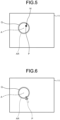
- FIG. 4 to FIG. 9 are diagrams illustrating examples of contents displayed on the display unit 11.
- the gaze point P of the subject is located on the target object Q and the subject is gazing at the target object Q.
- the gaze point P is located in the specific region AR including the target object Q.
- the index is not displayed until last 50 gaze points P counted from when the gaze point P is located in the specific region AR are successively sampled in the specific region AR.
- a moving index M is displayed at the position of the gaze point P as illustrated in FIG. 5 .
- the moving index M is displayed at the position of the sampled gaze point every time the gaze point P is sampled.
- the moving index M moves in accordance with movement of the gaze point P.
- FIG. 5 an example is illustrated in which the moving index M is represented by a black circle, but a display mode of the moving index M is not limited to this example. If the gaze point P is continuously located in the specific region AR, a state in which the moving index M is displayed is continued.
- the display control unit 31 is able to hide the moving index M as illustrated in FIG. 6 .
- a second presence time is equal to or larger than a predetermined time as a second index display condition (hereinafter, described as a "second condition")
- the display control unit 31 displays an index at the position corresponding to the gaze point on the display unit 11 at the time the second presence time becomes equal to or larger than the predetermined time.
- the second condition may be that, for example, last 50 gaze points P counted from when the moving index M is displayed are successively sampled in the specific region AR. Further, the index that is displayed when the second condition is met is the fixed index. Furthermore, if the second condition is met, counting of the gaze points P for the second condition is reset.
- the display control unit 31 displays the fixed index S at a position of the 50-th sampled gaze point P.
- the fixed index S is displayed in a fixed state at the position of the 50-th sampled gaze point P, independent of movement of the gaze point P.
- FIG. 7 an example is illustrated in which the fixed index S is represented by a white circle, but a display mode of the fixed index S is not limited to this example. If the gaze point P is continuously located in the specific region AR, the state in which the moving index M is displayed is continued. Due to the display of the single fixed index S, counting of the gaze points P for the second condition is reset.
- the display control unit 31 displays a fixed index S1 at a position of the 50-th sampled gaze point P.
- the fixed index S1 is represented by a white circle similarly to the fixed index S, but is not limited to this example, and a display mode may be different from that of the fixed index S.
- the display control unit 31 determines that the first condition is not met because the gaze point is not detected in the specific region AR. If the first condition is not met in the state in which the moving index M is being displayed, the display control unit 31 is able to hide the moving index M as illustrated in FIG. 9 . Meanwhile, in this case, the display control unit 31 is able to continuously display the fixed indices S and S1 on the display unit 11. Meanwhile, the fixed indices S and S1 may be hidden similarly to the moving index M.
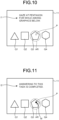
- FIG. 10 and FIG. 11 are diagrams illustrating other examples of contents displayed on the display unit 11.
- the display control unit 31 displays task information I1 and answer target objects Q1 to Q4 for the subject on the display unit 11, for example.
- the task information I1 indicates a task of gazing at a figure of a "pentagon" for a while.
- the answer target objects include the answer target object Q1 representing a triangle, the answer target object Q2 representing a quadrangle, the answer target object Q3 representing a pentagon, and the answer target object Q4 representing a hexagon.
- the region setting unit 33 sets the specific region AR in a region including the answer target object Q3 that is a correct answer (pentagon) of the task information I1.
- the display control unit 31 adopts the first condition as described above (last 50 gaze points P are successively sampled in the specific region AR) as the index display condition. Further, the index that is displayed when the first condition is met is the moving index M.
- the gaze point P of the subject stays within the specific region AR.
- the moving index M is displayed at the position of the gaze point P as illustrated in FIG. 11 .
- the display control unit 31 causes the display unit 11 to display instruction information I2 indicating that answering to the task is completed, by using the display of the moving index M as a trigger.
- the display control unit 31 causes the display unit 11 to display instruction information I2 indicating that answering to the task is completed, by using the display of the moving index M as a trigger.
- it is possible to adopt, as a condition for completion of answering a state in which the subject keeps gazing at the target object (the answer target object Q3) until the index (the moving index M) is displayed on the display unit 11.
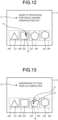
- FIG. 12 and FIG. 13 are diagrams illustrating contents displayed on the display unit 11.
- the display control unit 31 displays the task information I1 and the answer target objects Q1 to Q4 on the display unit 11 similarly to FIG. 10 .
- the region setting unit 33 sets the specific regions AR in regions including the respective answer target objects Q1 to Q4.
- the display control unit 31 adopts the first condition (last 50 gaze points P are successively sampled in the specific region AR) and the second condition (last 50 gaze points P are successively sampled in the specific region AR from when the moving index M is displayed) as the index display conditions.
- the index that is displayed when the first condition is met is the moving index M
- the index that is displayed when the second condition is met is the fixed index S.
- the moving index M is displayed at the position of the gaze point P as illustrated in FIG. 12 .
- the moving index M is displayed on the answer target object Q2. If the subject is recognizing that he/she is gazing at the answer target object Q3 for example, it is possible to correct the position of the gaze point P by moving a viewpoint to the right.
- the display control unit 31 may determine that answering is completed and display the fixed index S as illustrated in FIG. 13 . Meanwhile, in FIG. 13 , a state is illustrated in which the fixed index S overlaps with the moving index M, but embodiments are not limited to this example. Further, the display control unit 31 may display the instruction information I2 indicating that answering to the task is completed by using the display of the fixed index S as a trigger.
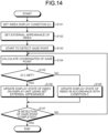
- FIG. 14 is a flowchart illustrating an example of the display method according to the present embodiment.
- an index display condition C is set (Step S101).
- the display control unit 31 outputs, to the output device 40, information for guiding a user to input the index display condition C via the input device 50 or the like, for example.
- the index display condition C is set based on a result of input by the input device 50.
- the index display condition C includes, for example, a position and a range of the specific region AR and a presence time of the gaze point P in the specific region AR.
- the region setting unit 33 sets the specific region AR on the display unit 11 on the basis of the set index display condition C.
- the display control unit 31 sets an external appearance of the index (Step S102).
- Step S102 similarly to Step S101, the display control unit 31 outputs, to the output device 40, candidates from among pieces of image data of indices stored in the storage unit 38, and guides the user to input a selection of image data via the input device 50 or the like. Then, the external appearance of the index is set based on a result of input by the input device 50.
- the gaze point detection unit 32 detects the gaze point P of the subject, and calculates the position of the detected gaze point P (Step S104).
- the determination unit 34 determines whether the gaze point P is present in the specific region AR with the same determination cycle as the sampling cycle of the gaze point detection unit 32 on the basis of the calculated position of the gaze point P, and outputs determination data.
- the arithmetic unit 35 calculates the presence time data of the gaze point P on the basis of the determination data of the determination unit 34.
- the display control unit 31 determines whether the gaze point P meets the index display condition C on the basis of the presence time data calculated by the arithmetic unit 35 (Step S105). If it is determined that the gaze point P meets the index display condition C (Yes at Step S105), the index set at Step S102 is displayed at the position of the gaze point P on the display unit 11 (Step S106). Further, if it is determined that the gaze point P does not meet the index display condition C (No at Step S105), the display mode of the gaze point P is updated in accordance with the index display condition C (Step S108).
- Step S108 for example, if the state in which the index of the gaze point P is displayed on the display unit 11 is changed to a state in which the index display condition C is not met, the display control unit 31 clears the displayed index. Further, if the index display condition C is not met while the index of the gaze point P is not being displayed on the display unit 11, the display control unit 31 maintains the state in which the index is not displayed on the display unit 11.
- Step S107 determines whether the detection of the gaze point P is completed. If it is determined that the detection of the gaze point P is completed (Yes at Step S107), the process is terminated. If it is determined that the detection of the gaze point P is not completed (No at Step S107), the processes from Step S104 are repeated.
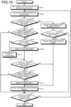
- FIG. 15 is a flowchart illustrating another example of the display method according to the present embodiment.
- an example is illustrated in which the moving index M and the fixed indices S, S1, ... are displayed.
- the index display condition is set and detection of the gaze point P is started (Step S201).
- a first index display condition hereinafter, described as an index display condition C1 for displaying the moving index M
- a second index display condition hereinafter, described as an index display condition C2 for displaying the fixed indices S, S1, ... are set.
- the index display condition C1 is that if the first presence time in the specific region AR is equal to or larger than a predetermined time, last 50 gaze points P are successively sampled in the specific region AR, for example.
- the index display condition C2 is that if the second presence time in the specific region AR is equal to or larger than a predetermined time, last 50 gaze points P are successively sampled in the specific region AR from when the moving index M is displayed, for example. Furthermore, if the index display condition C2 is met, counting of the gaze points P is reset.
- Step S201 external appearances of the moving index M and the fixed indices S, S1, ... are set.
- a position and a range of the specific region AR and a presence time of the gaze point P in the specific region AR are set.
- the gaze point detection unit 32 detects the gaze point P of the subject, and calculates the position of the detected gaze point P (Step S202).
- the determination unit 34 determines whether the gaze point P is present in the specific region AR with the same determination cycle as the sampling cycle of the gaze point detection unit 32 on the basis of the calculated position of the gaze point P, and outputs determination data, similarly to the above.
- the arithmetic unit 35 calculates the presence time data of the gaze point P on the basis of the determination data of the determination unit 34.
- the display control unit 31 determines whether the gaze point P is located in the specific region defined by the index display condition C1, on the basis of the presence time data calculated by the arithmetic unit 35 (Step S203). If it is determined that the gaze point P is located in the specific region AR (Yes at Step S203), the display control unit 31 determines whether the predetermined number of repetitions (in this example, 50 repetitions) as defined by the index display condition C1 are performed (Step S204). If it is determined that the predetermined number of repetitions are performed (Yes at Step S204), the display control unit 31 determines whether the moving index is hidden (Step S205). If it is determined that the moving index is hidden (Yes at Step S205), the display control unit 31 displays the moving index M at the position of the gaze point P on the display unit 11 (Step S206).
- the predetermined number of repetitions in this example, 50 repetitions
- Step S203 if it is determined that the gaze point P is not located in the specific region AR (No at Step S203), the arithmetic unit 35 clears the successive number of times of determination for the index display condition C1 (Step S207). Thereafter, the display control unit 31 determines whether the moving index M is displayed (Step S208). If it is determined that the moving index M is displayed (Yes at Step S208), the displayed moving index M is cleared (Step S209), and processes from Step S214 to be described later are performed. If it is determined that the moving index M is not displayed (No at Step S208), processes from Step S215 to be described later are performed.
- Step S204 if it is determined that the gaze point P is located in the specific region AR but the predetermined number of repetitions are not performed (No at Step S204), the processes from Step S215 to be described later are performed.
- Step S205 if it is determined that the moving index M is not hidden (is already displayed) (No at Step S205), the display control unit 31 continues to display the moving index M (Step S210).
- the moving index M is displayed on the display unit 11.
- the display control unit 31 determines whether the gaze point P is located in the specific region defined by the index display condition C2 (Step S211).
- the specific regions defined by the index display conditions C1 and C2 are the same specific region AR, so that the determination result at Step S211 is the same as the result at Step S203.
- determination is performed at Step S211.
- Step S211 if it is determined that the gaze point P is located in the specific region defined by the index display condition C2 (Yes at Step S211), the display control unit 31 determines whether the predetermined number of repetitions (in this example, 50 repetitions) as defined by the index display condition C2 are performed (Step S212). If it is determined that the predetermined number of repetitions are performed (Yes at Step S212), the display control unit 31 displays the fixed index S at the position of the 50-th sampled gaze point P (Step S213). Thereafter, the counter for counting the successive number of times of determination for the index display condition C2 is reset (Step S214).
- the predetermined number of repetitions in this example, 50 repetitions
- Step S211 if it is determined that the gaze point P is not located in the specific region AR (No at Step S211), the processes from Step S214 are performed.
- Step S212 if it is determined that the gaze point P is located in the specific region AR but the predetermined number of repetitions are not performed (No at Step S212), the processes from Step S215 to be described later are performed.
- Step S215 determines whether the detection of the gaze point P is completed. If it is determined that detection of the gaze point P is completed (Yes at Step S215), the process is terminated. If it is determined that detection of the gaze point P is not completed (No at Step S215), the processes from Step S202 are repeated.
- the display apparatus 100 includes the display unit 11 that displays a predetermined target object to be gazed at by a subject, the gaze point detection unit 32 that detects positions of gaze points of the subject who observes the display unit 11, the region setting unit 33 that sets the specific region AR corresponding to the predetermined target object, the determination unit 34 that determines whether each of the gaze points is present in the specific region AR, the arithmetic unit 35 that calculates gaze point data on the basis of a determination result of the determination unit 34, and the display control unit 31 that displays an index at a position corresponding to a gaze point on the display unit 11 if the gaze point data meets the index display condition.
- the display method includes displaying a predetermined target object to be gazed at by a subject on the display unit 11, detecting positions of gaze points of the subject who observes the display unit 11, setting the specific region AR corresponding to the predetermined target object, determining whether each of the gaze points is present in the specific region AR, calculating gaze point data on the basis of a determination result, and displaying an index at a position corresponding to a gaze point on the display unit 11 if the gaze point data meets an index display condition.
- a display program causes a computer to perform a process of displaying a predetermined target object to be gazed at by a subject on the display unit 11, a process of detecting positions of gaze points of the subject who observes the display unit 11, a process of setting the specific region AR corresponding to the predetermined target object, a process of determining whether each of the gaze points is present in the specific region AR, a process of calculating gaze point data on the basis of a determination result, and a process of displaying an index at a position corresponding to a gaze point on the display unit 11 if the gaze point data meets an index display condition.
- the display control unit 31 causes the display unit 11 to display the index at the position corresponding to the gaze point P.
- the gaze point data includes a first presence time in which the gaze points are successively present in the specific region AR
- a predetermined index display condition includes a first index display condition
- the first index display condition is that if the first presence time is equal to or larger than a predetermined time, the moving index M is displayed as the index at a position corresponding to a gaze point on the display unit every time the position of the gaze point is detected.
- the gaze point data includes a second presence time in which the gaze points are successively present in the specific region AR
- the predetermined index display condition includes a second index display condition
- the second index display condition is that if the second presence time is equal to or larger than a predetermined time, the fixed index S is displayed as the index at a position corresponding to a gaze point on the display unit 11 at the time the gaze point data meets the second index display condition.
- the second index display condition is that the fixed index S is displayed when the second presence time is equal to or larger than a predetermined time after the moving index is displayed under the first index display condition.
- a display apparatus, a display method, and a display program according to the present disclosure may be adopted to, for example, a line-of-sight detection apparatus.
Landscapes
- Health & Medical Sciences (AREA)
- Life Sciences & Earth Sciences (AREA)
- Engineering & Computer Science (AREA)
- Heart & Thoracic Surgery (AREA)
- Molecular Biology (AREA)
- Biophysics (AREA)
- Ophthalmology & Optometry (AREA)
- Biomedical Technology (AREA)
- Veterinary Medicine (AREA)
- Medical Informatics (AREA)
- Physics & Mathematics (AREA)
- Surgery (AREA)
- Animal Behavior & Ethology (AREA)
- General Health & Medical Sciences (AREA)
- Public Health (AREA)
- Human Computer Interaction (AREA)
- Eye Examination Apparatus (AREA)
- User Interface Of Digital Computer (AREA)
Description
- The present disclosure relates to a display apparatus, a display method, and a display program.
- Visual cognitive functions include a function to input information from eyes and a function to recognize the input information. In the function to input information from eyes, visual performance, such as eye movement, for looking at a target object is important. As a method of evaluating the visual performance, for example, a technology for displaying a graphic on a display unit, requesting a subject to gaze at the graphic, detecting a position of a gaze point, and calculating a gaze time in a predetermined region of the graphic has been disclosed (for example, see
JP 2017-158868 A -
WO 2017 213 070 A discloses an information processing device and method and a recording medium which controls a display device disposed along a prescribed direction within the visual field of a user, the display device being controlled so as to display a stereoscopic object that indicates distance pertaining to the prescribed direction. -
WO 2017 031 089 A discloses systems and methods for discerning the intent of a device wearer primarily based on movements of the eyes. The system may be included within unobtrusive headwear that performs eye tracking and controls screen display. The system may also utilize remote eye tracking camera(s), remote displays and/or other ancillary inputs. Screen layout is optimized to facilitate the formation and reliable detection of rapid eye signals. The detection of eye signals is based on tracking physiological movements of the eye that are under voluntary control by the device wearer. The detection of eye signals results in actions that are compatible with wearable computing and a wide range of display devices. -
US 2014 253 876 A discloses systems, devices, and methods for the assessment, screening, monitoring, or diagnosis of developmental or cognitive conditions, including autism spectrum disorders (ASD) by analysis of eye tracking data generated from feedback received as a result of display of specific predetermined visual stimuli to a subject or patient. Subsequent to a calibration phase, a testing procedure is performed by presenting predetermined stimuli (e.g., videos) to a subject via a display device. Eye tracking data (from the subject moving his or her eyes in response to predetermined movies or other visual stimuli) are collected. During the data collection period, the system periodically presents targets to reflexively elicit the subject's gaze. These data are used to later verify accuracy. Analysis of the subject's viewing patterns during these stimuli is used for the assessment, screening, monitoring, or diagnosis of developmental or cognitive conditions such as ASD. -
US 2016 209 917 A discloses a method to provide visual feedback for gazed-based user-interface navigation includes presenting, on a display, a first image representing a digital object available for user interaction, recognizing a user gaze axis, and computing a point of intersection of the user gaze axis through the first image. An offset distance between the point of intersection and a reference position of the first image then recognized, and a second image is presented on the display. The second image is presented displaced from the point of intersection by an amount dependent on the offset distance. -
US 2019 073024 A discloses a gaze detection device which includes a display screen configured to display an image; a sound output device configured to output a sound; a gaze point detector configured to detect a position of a point of gaze of an observer observing the display screen; an area setting unit configured to set a specific area on the display screen or part of the image; a determination unit configured to, when the specific area is set on the display screen or the image, determine whether the point of gaze is within the specific area on the basis of a result of the detecting the position of the point of gaze; and an output controller configured to cause the display screen to display the image and cause the sound output device to output the sound and adjust at least a mode in which the sound is output. - In the technology described in
JP 2017-158868 A JP 2017-158868 A - The present disclosure has been conceived in view of the foregoing situation, and an object of the present disclosure is to provide a display apparatus, a display method, and a display program capable of giving feedback on a state of visual performance to a subject.
- In accordance with the present invention, a display apparatus, a display method, and a display program as set forth in the appended claims is provided.
- A display apparatus according to the present disclosure comprises the features of
claim 1. - A display method according to the present disclosure comprises the steps of claim 4.
- A display program according to the present disclosure is defined by the features of claim 5.
- According to the present disclosure, it is possible to provide a display apparatus, a display method, and a display program capable of giving feedback on a state of visual performance to a subject.
-
-
FIG. 1 is a diagram schematically illustrating an example of a display apparatus according to the present embodiment. -
FIG. 2 is a functional block diagram illustrating an example of the display apparatus. -
FIG. 3 is a diagram illustrating an example of contents displayed on a display unit. -
FIG. 4 is a diagram illustrating an example of contents displayed on the display unit. -
FIG. 5 is a diagram illustrating an example of contents displayed on the display unit. -
FIG. 6 is a diagram illustrating an example of contents displayed on the display unit. -
FIG. 7 is a diagram illustrating an example of contents displayed on the display unit. -
FIG. 8 is a diagram illustrating an example of contents displayed on the display unit. -
FIG. 9 is a diagram illustrating an example of contents displayed on the display unit. -
FIG. 10 is a diagram illustrating another example of contents displayed on the display unit. -
FIG. 11 is a diagram illustrating still another example of contents displayed on the display unit. -
FIG. 12 is a diagram illustrating still another example of contents displayed on the display unit. -
FIG. 13 is a diagram illustrating still another example of contents displayed on the display unit. -
FIG. 14 is a flowchart illustrating an example of a display method according to the present embodiment. -
FIG. 15 is a flowchart illustrating another example of the display method according to the present embodiment. Description of Embodiments - Embodiments of a display apparatus, a display method, and a display program according to the present disclosure will be described below based on the drawings. The disclosure is not limited by the embodiments below. In addition, structural elements in the embodiments described below include one that can easily be thought of by a person skilled in the art and one that is practically identical.
- In the description below, the three-dimensional global coordinate system is set to describe positional relationships between components. A direction parallel to a first axis of a predetermined plane will be referred to as an X-axis direction, a direction parallel to a second axis of the predetermined plane perpendicular to the first axis will be referred to as an Y-axis direction, and a direction parallel to a third axis perpendicular to each of the first axis and the second axis will be referred to as a Z-axis direction. The predetermined plane includes an XY plane.
-
FIG. 1 is a diagram schematically illustrating an example of adisplay apparatus 100 according to the present embodiment. Thedisplay apparatus 100 according to the present embodiment detects a line of sight of a subject, and gives feedback on a state of visual performance to the subject by using a detection result. As thedisplay apparatus 100, various apparatuses capable of detecting a line of sight of a subject, such as an apparatus that detects the line of sight on the basis of a position of a pupil of the subject and a position of a corneal reflection image and an apparatus that detects the line of sight on the basis of a position of an inner corner of an eye of the subject and a position of an iris of the subject, may be used, for example. - As illustrated in
FIG. 1 , thedisplay apparatus 100 includes adisplay device 10, animage acquisition device 20, acomputer system 30, anoutput device 40, aninput device 50, and an input-output interface device 60. Thedisplay device 10, theimage acquisition device 20, thecomputer system 30, theoutput device 40, and theinput device 50 perform data communication via the input-output interface device 60. Each of thedisplay device 10 and theimage acquisition device 20 includes a driving circuit (not illustrated). - The
display device 10 includes a flat panel display, such as a liquid crystal display (LCD) or an organic electroluminescence display (OLED). In the present embodiment, thedisplay device 10 includes adisplay unit 11. Thedisplay unit 11 displays information, such as an image. Thedisplay unit 11 is substantially parallel to the XY plane. The X-axis direction is a horizontal direction of thedisplay unit 11, the Y-axis direction is a vertical direction of thedisplay unit 11, and the Z-axis direction is a depth direction perpendicular to thedisplay unit 11. Thedisplay device 10 may be a head mounted display device. If thedisplay device 10 is a head mounted display device, a component like theimage acquisition device 20 is arranged in a head mounted module. - The
image acquisition device 20 acquires image data of left and right eyeballs EB of the subject, and transmits the acquired image data to thecomputer system 30. Theimage acquisition device 20 includes animaging device 21. Theimaging device 21 captures images of the left and right eyeballs EB of the subject and acquires image data. Theimaging device 21 includes various cameras corresponding to methods of detecting the line of sight of the subject. For example, if a method of detecting the line of sight based on a position of a pupil of the subject and a position of a corneal reflection image is adopted, theimaging device 21 includes an infrared camera, an optical system capable of transmitting near-infrared light at a wavelength of 850 nm, and an imaging element capable of receiving the near-infrared light, for example. Further, for example, if a method of detecting the line of sight based on a position of an inner corner of an eye of the subject and a position of an iris of the subject is adopted, theimaging device 21 includes a visible light camera. Theimaging device 21 outputs a frame synchronous signal. A cycle of the frame synchronous signal may be, for example, 20 milliseconds (msec), but is not limited thereto. Theimaging device 21 may be configured as, for example, a stereo camera including afirst camera 21A and asecond camera 21B, but is not limited thereto. - Furthermore, for example, if the method of detecting the line of sight based on the position of the pupil of the subject and the position of the corneal reflection image is adopted, the
image acquisition device 20 includes alighting device 22 that illuminates the eyeballs EB of the subject. Thelighting device 22 includes a light emitting diode (LED) light source, for example, and is able to emit near-infrared light at a wavelength of 850 nm. Meanwhile, for example, if a method of detecting a line-of-sight vector based on the position of the inner corner of the eye of the subject and the position of the iris of the subject is adopted, thelighting device 22 may be omitted. Thelighting device 22 emits detection light in synchronization with the frame synchronous signal of theimaging device 21. Thelighting device 22 may include, for example, a firstlight source 22A and a secondlight source 22B, but is not limited thereto. - The
computer system 30 integrally controls operation of thedisplay apparatus 100. Thecomputer system 30 includes anarithmetic processing device 30A and astorage device 30B. Thearithmetic processing device 30A includes a microprocessor, such as a central processing unit (CPU). Thestorage device 30B includes a memory, such as a read only memory (ROM) and a random access memory (RAM), or a storage. Thearithmetic processing device 30A performs an arithmetic process in accordance with acomputer program 30C that is stored in thestorage device 30B. - The
output device 40 includes a display device, such as a flat panel display. Meanwhile, theoutput device 40 may include a printing device. Theinput device 50 generates input data by being operated. Theinput device 50 includes a keyboard or a mouse for a computer system. Meanwhile, theinput device 50 may include a touch sensor that is arranged on a display unit of theoutput device 40 that is a display device. - In the
display apparatus 100 according to the present embodiment, thedisplay device 10 and thecomputer system 30 are separate devices. Meanwhile, thedisplay device 10 and thecomputer system 30 may be integrated. For example, thedisplay apparatus 100 may include a tablet personal computer. In this case, the display device, the image acquisition device, the computer system, the input device, the output device, and the like may be mounted on the tablet personal computer. -
FIG. 2 is a functional block diagram illustrating an example of thedisplay apparatus 100. As illustrated inFIG. 2 , thecomputer system 30 includes adisplay control unit 31, a gazepoint detection unit 32, aregion setting unit 33, adetermination unit 34, anarithmetic unit 35, anevaluation unit 36, an input-output control unit 37, and astorage unit 38. Functions of thecomputer system 30 are implemented by thearithmetic processing device 30A and thestorage device 30B (seeFIG. 1 ). Meanwhile, a part of the functions of thecomputer system 30 may be arranged outside thedisplay apparatus 100. - The gaze
point detection unit 32 detects positional data of a gaze point of the subject. In the present embodiment, the gazepoint detection unit 32 detects a line-of-sight vector of the subject defined by the three-dimensional global coordinate system, on the basis of the image data of the left and right eyeballs EB of the subject acquired by theimage acquisition device 20. The gazepoint detection unit 32 detects positional data of an intersection of the detected line-of-sight vector of the subject and thedisplay unit 11 of thedisplay device 10, as the positional data of the gaze point of the subject. In other words, in the present embodiment, the positional data of the gaze point is the positional data of the intersection of the line-of-sight vector of the subject and thedisplay unit 11 of thedisplay device 10 defined by the three-dimensional global coordinate system. In the present embodiment, the gaze point is a designated point that is designated on thedisplay unit 11 by being gazed at by the subject. The gazepoint detection unit 32 detects the positional data of the gaze point of the subject for each prescribed sampling cycle. The sampling cycle may be, for example, the cycle (for example, every 20 msec) of the frame synchronous signal output from theimaging device 21. - The
region setting unit 33 sets specific regions in thedisplay unit 11. The specific regions may have various planner shapes, such as circles, ellipses, polygons, or combinational shapes of circles, ellipses, and polygons, for example. Theregion setting unit 33 may set the specific regions in theentire display unit 11 or may set the specific regions in a part of thedisplay unit 11. In the present embodiment, each of the regions set by theregion setting unit 33 is not displayed on thedisplay unit 11 in principle. Meanwhile, each of the regions may be displayed on thedisplay unit 11 under the control of thedisplay control unit 31, for example. - The
determination unit 34 determines whether the gaze point is present in a specific region in a period in which theregion setting unit 33 sets the specific region, and outputs determination data. Thedetermination unit 34 determines whether the gaze point is present in the specific region for each prescribed determination cycle. The determination cycle may be, for example, the same cycle as the cycle (for example, every 20 msec) of the frame synchronous signal output from theimaging device 21. In this case, the determination cycle of thedetermination unit 34 is the same as the sampling cycle of the gazepoint detection unit 32. - The
arithmetic unit 35 calculates gaze point data that indicates a course of movement of the gaze point in the period in which the specific region is set as described above, on the basis of the determination data of thedetermination unit 34. Thearithmetic unit 35 calculates presence time data as the gaze point data, for example. The presence time data is data that indicates presence time in which the gaze point is present in the specific region. It is possible to estimate that the presence time in which the gaze point is present in the specific region increases with an increase in the number of times that thedetermination unit 34 determines that the gaze point is present in the specific region. Therefore, in the present embodiment, it is assumed that the presence time is the number of times of determination made by thedetermination unit 34. In other words, it is assumed that the presence time is the number of samplings of gaze points detected in the specific region. Thearithmetic unit 35 includes a counter that counts the number of times that thedetermination unit 34 determines that the gaze point is present in the specific region. - The
display control unit 31 displays an evaluation image for evaluating visual performance of the subject on thedisplay unit 11. A display mode of the evaluation image may be any of a moving image and a still image. Further, if the gaze point data meets an index display condition, thedisplay control unit 31 displays an index at a position corresponding to the gaze point on thedisplay unit 11. In this case, if the presence time is equal to or larger than a predetermined time as the index display condition, thedisplay control unit 31 displays the index on thedisplay unit 11. - The index includes, for example, a moving index and a fixed index. The moving index is displayed at the position of the gaze point every time the gaze
point detection unit 32 detects the gaze point. In other words, the moving index is displayed at a position of a sampled gaze point every time the gazepoint detection unit 32 performs sampling. The fixed index is displayed at the position of the gaze point at the time the gaze point data meets the index display condition. In other words, the fixed index is displayed at a position of a gaze point that meets the index display condition. - As an external appearance of the index, the index may have various shapes, such as a circle, an ellipse, a polygon, or a combinational shape of a circle, an ellipse, and a polygon, for example. Further, the shape of the index is not limited to a geometric shape, and may be an image representing an animal, a plant, or the like. As the external appearance of the index, the index may have any color as long as the color is displayable on the
display unit 11, and may have a single color or a mixed color of a plurality of colors, for example. As the external appearance of the index, the index may have any size as long as the size is displayable on thedisplay unit 11, for example. Thedisplay control unit 31 hides the index if the gaze point data does not meet the index display condition while the index is being displayed on thedisplay unit 11. The index as described above is stored, as index data, in thestorage unit 38. - The
evaluation unit 36 obtains evaluation data of the subject on the basis of the gaze point data. The evaluation data includes, for example, data for evaluating whether the subject is able to gaze at a predetermined region in the evaluation image displayed on thedisplay unit 11. - The input-
output control unit 37 acquires data (the image data of the eyeballs EB, the input data, or the like) from at least one of theimage acquisition device 20 and theinput device 50. Further, the input-output control unit 37 outputs data to at least one of thedisplay device 10 and theoutput device 40. The input-output control unit 37 may output a task for the subject from theoutput device 40, such as a speaker. - The
storage unit 38 stores therein the determination data, the gaze point data (the presence time data), and the index data as described above. Further, thestorage unit 38 stores therein a display program that causes a computer to perform a process of detecting positions of gaze points of the subject who observes thedisplay unit 11, a process of setting a specific region in thedisplay unit 11, a process of determining whether each of the gaze points is present in the specific region, a process of calculating the gaze point data on the basis of a determination result, and a process of displaying an index at a position corresponding to the gaze point on thedisplay unit 11 if the gaze point data meets the index display condition. - A display method according to the present embodiment will be described below. In the display method according to the present embodiment, feedback on a state of visual performance is given to the subject by using the
display apparatus 100 as described above. -
FIG. 3 is a diagram illustrating an example of contents displayed on thedisplay unit 11. Thedisplay control unit 31 displays the evaluation image for evaluating the visual performance of the subject on thedisplay unit 11. Thedisplay control unit 31 displays, for example, a target object Q on thedisplay unit 11. The target object Q has, for example, a circular shape. Meanwhile, it is possible to cause thedisplay unit 11, theoutput device 40, or the like to give, in advance, an instruction to gaze at the target object Q for a while to the subject. Meanwhile, the target object Q need not always have a circular shape. - The
region setting unit 33 sets a specific region AR corresponding to the target object Q. In the present embodiment, the specific region AR is a circle centered at a reference position A. Meanwhile, the specific region AR need not always have a circular shape, but may have a different shape. The reference position A may be, for example, a center position of the target object Q. Theregion setting unit 33 is able to set the specific region AR in a region including the target object Q, for example. - The gaze
point detection unit 32 detects a position of a gaze point P of the subject on thedisplay unit 11 for each prescribed sampling cycle (for example, 20 msec). While the position of the gaze point P detected by the gazepoint detection unit 32 is represented by a dashed line on thedisplay unit 11, the gaze point P is not displayed on thedisplay unit 11 at the time as illustrated inFIG. 3 . If the gaze point P is not displayed as described above, it is difficult for the subject to recognize a position at which the subject is gazing at. For example, if a position that the subject recognizes as a gaze position and a position of the detected gaze point are different, it is difficult to recognize deviation between the gaze position recognized by the subject and the position of the detected gaze point, so that, in some cases, a result indicating a gaze at a position that is different from the position recognized by the subject may be obtained. - In the present embodiment, the
display control unit 31 displays an index at a position corresponding to the gaze point P on thedisplay unit 11 if the gaze point data meets the index display condition. By allowing the subject to recognize a position at which the subject is gazing in real time, it is possible to give the subject an opportunity to correct the position of the gaze point P if the gaze position recognized by the subject and the position of the detected gaze point are different, for example. - The
determination unit 34 determines whether the gaze point P is present in the specific region AR in a period in which theregion setting unit 33 sets the specific region AR, and outputs determination data. Thedetermination unit 34 determines whether the gaze point P is present in the specific region AR for each prescribed determination cycle. The determination cycle is the same as the sampling cycle of the gazepoint detection unit 32. - The
arithmetic unit 35 calculates the gaze point data that indicates a course of movement of the gaze point P in the period in which the specific region AR is set, on the basis of the determination data of thedetermination unit 34. Thearithmetic unit 35 calculates the presence time data as the gaze point data, for example. - If the gaze point data meets the index display condition, the
display control unit 31 displays the index at the position corresponding to the gaze point P on thedisplay unit 11. In this case, if a first presence time is equal to or larger than a predetermined time as a first index display condition (hereinafter, described as a "first condition"), thedisplay control unit 31 displays an index at the position corresponding to the gaze point on thedisplay unit 11 every time the position of the gaze point is detected. The index is displayed on thedisplay unit 11. The first condition may be that, for example, last 50 gaze points P are successively sampled in the specific region AR. Further, the index that is displayed when the first condition is met is the moving index. -
FIG. 4 to FIG. 9 are diagrams illustrating examples of contents displayed on thedisplay unit 11. In the case as illustrated inFIG. 4 , the gaze point P of the subject is located on the target object Q and the subject is gazing at the target object Q. In this case, the gaze point P is located in the specific region AR including the target object Q. The index is not displayed until last 50 gaze points P counted from when the gaze point P is located in the specific region AR are successively sampled in the specific region AR. - If 50 gaze points P are successively sampled at positions in the specific region AR, a moving index M is displayed at the position of the gaze point P as illustrated in
FIG. 5 . The moving index M is displayed at the position of the sampled gaze point every time the gaze point P is sampled. In other words, the moving index M moves in accordance with movement of the gaze point P. InFIG. 5 , an example is illustrated in which the moving index M is represented by a black circle, but a display mode of the moving index M is not limited to this example. If the gaze point P is continuously located in the specific region AR, a state in which the moving index M is displayed is continued. - In contrast, if the gaze point P of the subject is detected outside the specific region AR while the moving index M is being displayed, the first condition is not met because the gaze point is not detected in the specific region AR. In this manner, if it becomes impossible to meet the first condition while the moving index M is being displayed, the
display control unit 31 is able to hide the moving index M as illustrated inFIG. 6 . - If a second presence time is equal to or larger than a predetermined time as a second index display condition (hereinafter, described as a "second condition"), the
display control unit 31 displays an index at the position corresponding to the gaze point on thedisplay unit 11 at the time the second presence time becomes equal to or larger than the predetermined time. The second condition may be that, for example, last 50 gaze points P counted from when the moving index M is displayed are successively sampled in the specific region AR. Further, the index that is displayed when the second condition is met is the fixed index. Furthermore, if the second condition is met, counting of the gaze points P for the second condition is reset. - For example, if last 50 gaze points P are successively sampled in the specific region AR from when the moving index M is displayed as illustrated in
FIG. 5 , the second condition is met. Therefore, in this case, as illustrated inFIG. 7 , thedisplay control unit 31 displays the fixed index S at a position of the 50-th sampled gaze point P. The fixed index S is displayed in a fixed state at the position of the 50-th sampled gaze point P, independent of movement of the gaze point P. InFIG. 7 , an example is illustrated in which the fixed index S is represented by a white circle, but a display mode of the fixed index S is not limited to this example. If the gaze point P is continuously located in the specific region AR, the state in which the moving index M is displayed is continued. Due to the display of the single fixed index S, counting of the gaze points P for the second condition is reset. - Therefore, if last 50 gaze points P are successively sampled in the specific region AF from when the moving index M and the fixed index S are displayed, the second condition is met again. In this case, as illustrated in
FIG. 8 , thedisplay control unit 31 displays a fixed index S1 at a position of the 50-th sampled gaze point P. The fixed index S1 is represented by a white circle similarly to the fixed index S, but is not limited to this example, and a display mode may be different from that of the fixed index S. For example, it may be possible to make setting such that the fixed index S is displayed in response to an instruction to gaze at the target object Q for a while. In this case, it is possible to determine that the visual performance is normal by displaying the fixed index S. - If the gaze point P of the subject is detected outside the specific region AR while the moving index M and the fixed indices S and S1 are being displayed, the
display control unit 31 determines that the first condition is not met because the gaze point is not detected in the specific region AR. If the first condition is not met in the state in which the moving index M is being displayed, thedisplay control unit 31 is able to hide the moving index M as illustrated inFIG. 9 . Meanwhile, in this case, thedisplay control unit 31 is able to continuously display the fixed indices S and S1 on thedisplay unit 11. Meanwhile, the fixed indices S and S1 may be hidden similarly to the moving index M. -
FIG. 10 and FIG. 11 are diagrams illustrating other examples of contents displayed on thedisplay unit 11. As illustrated inFIG. 10 , thedisplay control unit 31 displays task information I1 and answer target objects Q1 to Q4 for the subject on thedisplay unit 11, for example. In the present embodiment, an example is illustrated in which the task information I1 indicates a task of gazing at a figure of a "pentagon" for a while. The answer target objects include the answer target object Q1 representing a triangle, the answer target object Q2 representing a quadrangle, the answer target object Q3 representing a pentagon, and the answer target object Q4 representing a hexagon. Theregion setting unit 33 sets the specific region AR in a region including the answer target object Q3 that is a correct answer (pentagon) of the task information I1. Thedisplay control unit 31 adopts the first condition as described above (last 50 gaze points P are successively sampled in the specific region AR) as the index display condition. Further, the index that is displayed when the first condition is met is the moving index M. - If the subject gazes at the answer target object Q3 representing a pentagon for a while, the gaze point P of the subject stays within the specific region AR. In this state, if 50 gaze points P are successively sampled at positions in the specific region AR, the moving index M is displayed at the position of the gaze point P as illustrated in
FIG. 11 . Thedisplay control unit 31 causes thedisplay unit 11 to display instruction information I2 indicating that answering to the task is completed, by using the display of the moving index M as a trigger. In this manner, it is possible to adopt, as a condition for completion of answering, a state in which the subject keeps gazing at the target object (the answer target object Q3) until the index (the moving index M) is displayed on thedisplay unit 11. In this case, it is possible to allow the subject to easily recognize the idea of an answering method in which answering is completed by gazing at the answer target object for a while. -
FIG. 12 and FIG. 13 are diagrams illustrating contents displayed on thedisplay unit 11. As illustrated inFIG. 12 , thedisplay control unit 31 displays the task information I1 and the answer target objects Q1 to Q4 on thedisplay unit 11 similarly toFIG. 10 . Meanwhile, in the example illustrated inFIG. 12 , theregion setting unit 33 sets the specific regions AR in regions including the respective answer target objects Q1 to Q4. Thedisplay control unit 31 adopts the first condition (last 50 gaze points P are successively sampled in the specific region AR) and the second condition (last 50 gaze points P are successively sampled in the specific region AR from when the moving index M is displayed) as the index display conditions. Further, the index that is displayed when the first condition is met is the moving index M, and the index that is displayed when the second condition is met is the fixed index S. - Under the conditions as described above, if the subject gazes at any of the answer target objects Q1 to Q4 representing a pentagon for a while, the gaze point P of the subject stays within the specific region AR. In this state, if the first condition is met, in other words, if 50 gaze points P are successively sampled at positions in the specific region AR, the moving index M is displayed at the position of the gaze point P as illustrated in
FIG. 12 . By displaying the moving index M, if the position that the subject recognizes as a gaze position and the position of the detected gaze point are different for example, it is possible to give the subject an opportunity to correct the position of the gaze point P. For example, in the example illustrated inFIG. 12 , the moving index M is displayed on the answer target object Q2. If the subject is recognizing that he/she is gazing at the answer target object Q3 for example, it is possible to correct the position of the gaze point P by moving a viewpoint to the right. - Further, if the subject continuous to gaze at the same region in the state in which the moving index M is displayed at the position corresponding to any of the predetermined answer target objects Q1 to Q4 and the second condition is met, in other words, 50 gaze points P are successively sampled at positions in the specific region, the
display control unit 31 may determine that answering is completed and display the fixed index S as illustrated inFIG. 13 . Meanwhile, inFIG. 13 , a state is illustrated in which the fixed index S overlaps with the moving index M, but embodiments are not limited to this example. Further, thedisplay control unit 31 may display the instruction information I2 indicating that answering to the task is completed by using the display of the fixed index S as a trigger. With this configuration, it is possible to display the moving index M to give the subject an opportunity to correct deviation of the position of the gaze point, determine an answer that is finally gazed at by the subject by using the fixed index S, and terminate the examination. Therefore, it is possible to perform evaluation based on the determined answer. -
FIG. 14 is a flowchart illustrating an example of the display method according to the present embodiment. InFIG. 14 , an example is illustrated in which the moving index M is displayed. As illustrated inFIG. 14 , first, an index display condition C is set (Step S101). At Step S101, thedisplay control unit 31 outputs, to theoutput device 40, information for guiding a user to input the index display condition C via theinput device 50 or the like, for example. Then, the index display condition C is set based on a result of input by theinput device 50. The index display condition C includes, for example, a position and a range of the specific region AR and a presence time of the gaze point P in the specific region AR. Theregion setting unit 33 sets the specific region AR on thedisplay unit 11 on the basis of the set index display condition C. - Subsequently, the
display control unit 31 sets an external appearance of the index (Step S102). At Step S102, similarly to Step S101, thedisplay control unit 31 outputs, to theoutput device 40, candidates from among pieces of image data of indices stored in thestorage unit 38, and guides the user to input a selection of image data via theinput device 50 or the like. Then, the external appearance of the index is set based on a result of input by theinput device 50. - Then, detection of the gaze point is started (Step S103). The gaze
point detection unit 32 detects the gaze point P of the subject, and calculates the position of the detected gaze point P (Step S104). Thedetermination unit 34 determines whether the gaze point P is present in the specific region AR with the same determination cycle as the sampling cycle of the gazepoint detection unit 32 on the basis of the calculated position of the gaze point P, and outputs determination data. Thearithmetic unit 35 calculates the presence time data of the gaze point P on the basis of the determination data of thedetermination unit 34. - The
display control unit 31 determines whether the gaze point P meets the index display condition C on the basis of the presence time data calculated by the arithmetic unit 35 (Step S105). If it is determined that the gaze point P meets the index display condition C (Yes at Step S105), the index set at Step S102 is displayed at the position of the gaze point P on the display unit 11 (Step S106). Further, if it is determined that the gaze point P does not meet the index display condition C (No at Step S105), the display mode of the gaze point P is updated in accordance with the index display condition C (Step S108). At Step S108, for example, if the state in which the index of the gaze point P is displayed on thedisplay unit 11 is changed to a state in which the index display condition C is not met, thedisplay control unit 31 clears the displayed index. Further, if the index display condition C is not met while the index of the gaze point P is not being displayed on thedisplay unit 11, thedisplay control unit 31 maintains the state in which the index is not displayed on thedisplay unit 11. - After the process at Step S106 or Step S108, the
arithmetic unit 35 determines whether the detection of the gaze point P is completed (Step S107). If it is determined that the detection of the gaze point P is completed (Yes at Step S107), the process is terminated. If it is determined that the detection of the gaze point P is not completed (No at Step S107), the processes from Step S104 are repeated. -
FIG. 15 is a flowchart illustrating another example of the display method according to the present embodiment. InFIG. 15 , an example is illustrated in which the moving index M and the fixed indices S, S1, ... are displayed. As illustrated inFIG. 15 , first, the index display condition is set and detection of the gaze point P is started (Step S201). At Step S201, a first index display condition (hereinafter, described as an index display condition C1) for displaying the moving index M and a second index display condition (hereinafter, described as an index display condition C2) for displaying the fixed indices S, S1, ... are set. Here, the index display condition C1 is that if the first presence time in the specific region AR is equal to or larger than a predetermined time, last 50 gaze points P are successively sampled in the specific region AR, for example. Further, the index display condition C2 is that if the second presence time in the specific region AR is equal to or larger than a predetermined time, last 50 gaze points P are successively sampled in the specific region AR from when the moving index M is displayed, for example. Furthermore, if the index display condition C2 is met, counting of the gaze points P is reset. Moreover, at Step S201, external appearances of the moving index M and the fixed indices S, S1, ... are set. Furthermore, at Step S201, a position and a range of the specific region AR and a presence time of the gaze point P in the specific region AR are set. - Subsequently, the gaze
point detection unit 32 detects the gaze point P of the subject, and calculates the position of the detected gaze point P (Step S202). Thedetermination unit 34 determines whether the gaze point P is present in the specific region AR with the same determination cycle as the sampling cycle of the gazepoint detection unit 32 on the basis of the calculated position of the gaze point P, and outputs determination data, similarly to the above. Thearithmetic unit 35 calculates the presence time data of the gaze point P on the basis of the determination data of thedetermination unit 34. - The
display control unit 31 determines whether the gaze point P is located in the specific region defined by the index display condition C1, on the basis of the presence time data calculated by the arithmetic unit 35 (Step S203). If it is determined that the gaze point P is located in the specific region AR (Yes at Step S203), thedisplay control unit 31 determines whether the predetermined number of repetitions (in this example, 50 repetitions) as defined by the index display condition C1 are performed (Step S204). If it is determined that the predetermined number of repetitions are performed (Yes at Step S204), thedisplay control unit 31 determines whether the moving index is hidden (Step S205). If it is determined that the moving index is hidden (Yes at Step S205), thedisplay control unit 31 displays the moving index M at the position of the gaze point P on the display unit 11 (Step S206). - Further, at Step S203, if it is determined that the gaze point P is not located in the specific region AR (No at Step S203), the
arithmetic unit 35 clears the successive number of times of determination for the index display condition C1 (Step S207). Thereafter, thedisplay control unit 31 determines whether the moving index M is displayed (Step S208). If it is determined that the moving index M is displayed (Yes at Step S208), the displayed moving index M is cleared (Step S209), and processes from Step S214 to be described later are performed. If it is determined that the moving index M is not displayed (No at Step S208), processes from Step S215 to be described later are performed. - Furthermore, at Step S204, if it is determined that the gaze point P is located in the specific region AR but the predetermined number of repetitions are not performed (No at Step S204), the processes from Step S215 to be described later are performed.
- Moreover, at Step S205, if it is determined that the moving index M is not hidden (is already displayed) (No at Step S205), the
display control unit 31 continues to display the moving index M (Step S210). - After the process at Step S206 or S210, the moving index M is displayed on the
display unit 11. In this state, thedisplay control unit 31 determines whether the gaze point P is located in the specific region defined by the index display condition C2 (Step S211). In the present embodiment, the specific regions defined by the index display conditions C1 and C2 are the same specific region AR, so that the determination result at Step S211 is the same as the result at Step S203. In contrast, if different specific regions are set for the index display condition C1 and the index display condition C2, determination is performed at Step S211. - At Step S211, if it is determined that the gaze point P is located in the specific region defined by the index display condition C2 (Yes at Step S211), the
display control unit 31 determines whether the predetermined number of repetitions (in this example, 50 repetitions) as defined by the index display condition C2 are performed (Step S212). If it is determined that the predetermined number of repetitions are performed (Yes at Step S212), thedisplay control unit 31 displays the fixed index S at the position of the 50-th sampled gaze point P (Step S213). Thereafter, the counter for counting the successive number of times of determination for the index display condition C2 is reset (Step S214). - Furthermore, at Step S211, if it is determined that the gaze point P is not located in the specific region AR (No at Step S211), the processes from Step S214 are performed. Moreover, at Step S212, if it is determined that the gaze point P is located in the specific region AR but the predetermined number of repetitions are not performed (No at Step S212), the processes from Step S215 to be described later are performed.
- After No at Step S204, No at Step S208, No at Step S212, or the process at Step S214, the
arithmetic unit 35 determines whether the detection of the gaze point P is completed (Step S215). If it is determined that detection of the gaze point P is completed (Yes at Step S215), the process is terminated. If it is determined that detection of the gaze point P is not completed (No at Step S215), the processes from Step S202 are repeated. - As described above, the
display apparatus 100 according to the present embodiment includes thedisplay unit 11 that displays a predetermined target object to be gazed at by a subject, the gazepoint detection unit 32 that detects positions of gaze points of the subject who observes thedisplay unit 11, theregion setting unit 33 that sets the specific region AR corresponding to the predetermined target object, thedetermination unit 34 that determines whether each of the gaze points is present in the specific region AR, thearithmetic unit 35 that calculates gaze point data on the basis of a determination result of thedetermination unit 34, and thedisplay control unit 31 that displays an index at a position corresponding to a gaze point on thedisplay unit 11 if the gaze point data meets the index display condition. - The display method according to the present embodiment includes displaying a predetermined target object to be gazed at by a subject on the
display unit 11, detecting positions of gaze points of the subject who observes thedisplay unit 11, setting the specific region AR corresponding to the predetermined target object, determining whether each of the gaze points is present in the specific region AR, calculating gaze point data on the basis of a determination result, and displaying an index at a position corresponding to a gaze point on thedisplay unit 11 if the gaze point data meets an index display condition. - A display program according to the present embodiment causes a computer to perform a process of displaying a predetermined target object to be gazed at by a subject on the
display unit 11, a process of detecting positions of gaze points of the subject who observes thedisplay unit 11, a process of setting the specific region AR corresponding to the predetermined target object, a process of determining whether each of the gaze points is present in the specific region AR, a process of calculating gaze point data on the basis of a determination result, and a process of displaying an index at a position corresponding to a gaze point on thedisplay unit 11 if the gaze point data meets an index display condition. - According to the present embodiment, if the gaze point data meets the index display condition, the
display control unit 31 causes thedisplay unit 11 to display the index at the position corresponding to the gaze point P. By allowing the subject to recognize a position gazed at by the subject in real time, if a position that the subject recognizes as a gaze position and a position of the detected gaze point are different for example, it is possible to allow the subject to recognize deviation between the gaze position recognized by the subject and the position of the detected gaze point, and give the subject an opportunity to correct deviation of the position of the gaze point P. With this configuration, it is possible to eliminate deviation between the gaze position recognized by the subject and the position of the detected gaze point, and display the gaze point of the subject. - In the
display apparatus 100 according to the present embodiment, the gaze point data includes a first presence time in which the gaze points are successively present in the specific region AR, a predetermined index display condition includes a first index display condition, and the first index display condition is that if the first presence time is equal to or larger than a predetermined time, the moving index M is displayed as the index at a position corresponding to a gaze point on the display unit every time the position of the gaze point is detected. By displaying the moving index M, it is possible to allow the subject to recognize deviation between the gaze position recognized by the subject and the position of the detected gaze point. With this configuration, it is possible to give the subject an opportunity to correct deviation of the position of the gaze point. - In the
display apparatus 100 according to the present embodiment, the gaze point data includes a second presence time in which the gaze points are successively present in the specific region AR, the predetermined index display condition includes a second index display condition, and the second index display condition is that if the second presence time is equal to or larger than a predetermined time, the fixed index S is displayed as the index at a position corresponding to a gaze point on thedisplay unit 11 at the time the gaze point data meets the second index display condition. By displaying the fixed index S, it is possible to recognize the final gaze point of the subject. - In the
display apparatus 100 according to the present embodiment, the second index display condition is that the fixed index S is displayed when the second presence time is equal to or larger than a predetermined time after the moving index is displayed under the first index display condition. With this configuration, it is possible to display the moving index M, give the subject an opportunity to correct deviation of the position of the gaze point, determine, by the fixed index S, an answer that is finally gazed at by the subject, and terminate the examination. Therefore, it is possible to perform evaluation based on the determined answer. - The technical scope of the present disclosure is not limited to the embodiments as described above, the invention being limited only by the scope of the appended claims.
- A display apparatus, a display method, and a display program according to the present disclosure may be adopted to, for example, a line-of-sight detection apparatus.
-
- A
- reference position
- C, C1, C2
- index display condition
- I1
- task information
- I2
- instruction information
- M
- moving index
- EB
- eyeball
- P
- gaze point
- Q
- target object
- Q1 to Q4
- answer target object
- S, S1
- fixed index
- AR
- specific region
- 10
- display device
- 11
- display unit
- 20
- image acquisition device
- 21
- imaging device
- 21A
- first camera
- 21B
- second camera
- 22
- lighting device
- 22A
- first light source
- 22B
- second light source
- 30
- computer system
- 30A
- arithmetic processing device
- 30B
- storage device
- 30C
- computer program
- 31
- display control unit
- 32
- gaze point detection unit
- 33
- region setting unit
- 34
- determination unit
- 35
- arithmetic unit
- 36
- evaluation unit
- 37
- input-output control unit
- 38
- storage unit
- 40
- output device
- 50
- input device
- 60
- input-output interface device
- 100
- display apparatus
Claims (5)
- A display apparatus (100) comprising:a display unit (11) configured to display a predetermined target object to be gazed at by a subject;a gaze point detection unit (32) configured to detect a position of a gaze point of the subject who observes the display unit (11);a region setting unit (33) configured to set a specific region corresponding to the predetermined target object;a determination unit (34) configured to determine whether the gaze point is present in the specific region;an arithmetic unit configured to calculate gaze point data on the basis of a determination result of the determination unit (34); anda display control unit (31) configured to, if the gaze point data meets a predetermined index display condition, display an index at a position corresponding to a gaze point of the subject on the display unit (11) in a period in which the gaze point detection unit (32) is detecting a position of a gaze point of the subject, whereinthe gaze point data includes a first presence time in which the gaze point is successively present in the specific region,the predetermined index display condition includes a first index display condition, andthe first index display condition is that if the first presence time is equal to or larger than a predetermined time, a moving index is displayed as the index at a position corresponding to the gaze point on the display unit (11) every time the position of the gaze point is detected, whereinthe gaze point data includes a second presence time in which the gaze point is successively present in the specific region,the predetermined index display condition includes a second index display condition, andthe second index display condition is that if the second presence time is equal to or larger than a predetermined time, a fixed index is displayed as the index at a position corresponding to the gaze point on the display unit (11) at the time the gaze point data meets the second index display condition, whereinthe second index display condition is that the fixed index is displayed when the second presence time is equal to or larger than a predetermined time after the moving index is displayed under the first index display condition, whereinafter the moving index is displayed, if the gaze point of the subject is detected outside the specific region, then the display control unit (31) is configured to stop displaying the moving index and is configured to continue displaying the fixed index independently from the movement of the gaze point of the subject.
- The display apparatus (100) according to claim 1, wherein a display mode of the fixed index is different from a display mode of the moving index.
- The display apparatus (100) according to claim 1 or 2, wherein the display control unit (31) is configured to display an instruction information indicating that answering to a task is completed by using the display of the fixed index as a trigger.
- A display method comprising:displaying a predetermined target object to be gazed at by a subject on a display unit (11);detecting by a gaze point detection unit (32) a position of a gaze point of the subject who observes the display unit (11);setting by a region setting unit (33) a specific region corresponding to the predetermined target object;determining by a determination unit (34) whether the gaze point is present in the specific region;calculating by an arithmetic unit gaze point data on the basis of a determination result; anddisplaying by a display control unit (31) configured to, if the gaze point data meets a predetermined index display condition, an index at a position corresponding to a gaze point of the subject on the display unit (11) in a period in which a position of a gaze point of the subject is being detected, whereinthe gaze point data includes a first presence time in which the gaze point is successively present in the specific region,the predetermined index display condition includes a first index display condition, andthe first index display condition is that if the first presence time is equal to or larger than a predetermined time, a moving index is displayed as the index at a position corresponding to the gaze point on the display unit (11) every time the position of the gaze point is detected, whereinthe gaze point data includes a second presence time in which the gaze point is successively present in the specific region,the predetermined index display condition includes a second index display condition, andthe second index display condition is that if the second presence time is equal to or larger than a predetermined time, a fixed index is displayed as the index at a position corresponding to the gaze point on the display unit (11) at the time the gaze point data meets the second index display condition, whereinthe second index display condition is that the fixed index is displayed when the second presence time is equal to or larger than a predetermined time after the moving index is displayed under the first index display condition, whereinthe displaying further includes stopping displaying the moving index after the moving index is displayed if the gaze point of the subject is detected outside the specific region, and continuing to display the fixed index independently from the movement of the gaze point of the subject.
- A display program that causes the display apparatus of claim 1 to execute:a process of displaying a predetermined target object to be gazed at by a subject on a display unit (11);a process of detecting a position of a gaze point of the subject who observes the display unit (11);a process of setting a specific region corresponding to the predetermined target object;a process of determining whether the gaze point is present in the specific region;a process of calculating gaze point data on the basis of a determination result; anda process of displaying, if the gaze point data meets a predetermined index display condition, an index at a position corresponding to a gaze point of the subject on the display unit (11) in a period in which a position of a gaze point of the subject is being detected,
whereinthe gaze point data includes a first presence time in which the gaze point is successively present in the specific region,the predetermined index display condition includes a first index display condition, andthe first index display condition is that if the first presence time is equal to or larger than a predetermined time, a moving index is displayed as the index at a position corresponding to the gaze point on the display unit (11) every time the position of the gaze point is detected, whereinthe gaze point data includes a second presence time in which the gaze point is successively present in the specific region,the predetermined index display condition includes a second index display condition, andthe second index display condition is that if the second presence time is equal to or larger than a predetermined time, a fixed index is displayed as the index at a position corresponding to the gaze point on the display unit (11) at the time the gaze point data meets the second index display condition, whereinthe second index display condition is that the fixed index is displayed when the second presence time is equal to or larger than a predetermined time after the moving index is displayed under the first index display condition, whereinthe displaying further includes stopping displaying the moving index after the moving index is displayed if the gaze point of the subject is detected outside the specific region, and continuing to display the fixed index independently from the movement of the gaze point of the subject.
Applications Claiming Priority (2)
| Application Number | Priority Date | Filing Date | Title |
|---|---|---|---|
| JP2019042988A JP7215246B2 (en) | 2019-03-08 | 2019-03-08 | Display device, display method, and display program |
| PCT/JP2019/044445 WO2020183792A1 (en) | 2019-03-08 | 2019-11-12 | Display device, display method and display program |
Publications (3)
| Publication Number | Publication Date |
|---|---|
| EP3922166A1 EP3922166A1 (en) | 2021-12-15 |
| EP3922166A4 EP3922166A4 (en) | 2022-03-30 |
| EP3922166B1 true EP3922166B1 (en) | 2023-05-10 |
Family
ID=72355003
Family Applications (1)
| Application Number | Title | Priority Date | Filing Date |
|---|---|---|---|
| EP19918516.6A Active EP3922166B1 (en) | 2019-03-08 | 2019-11-12 | Display device, display method and display program |
Country Status (4)
| Country | Link |
|---|---|
| US (1) | US20210386283A1 (en) |
| EP (1) | EP3922166B1 (en) |
| JP (1) | JP7215246B2 (en) |
| WO (1) | WO2020183792A1 (en) |
Families Citing this family (1)
| Publication number | Priority date | Publication date | Assignee | Title |
|---|---|---|---|---|
| JP7368838B2 (en) | 2019-12-27 | 2023-10-25 | 国際計測器株式会社 | impact test equipment |
Family Cites Families (10)
| Publication number | Priority date | Publication date | Assignee | Title |
|---|---|---|---|---|
| EP0055338A1 (en) * | 1980-12-31 | 1982-07-07 | International Business Machines Corporation | Eye controlled user-machine communication |
| JP5624512B2 (en) * | 2011-05-02 | 2014-11-12 | パナソニック株式会社 | Content evaluation apparatus, method, and program thereof |
| KR102179931B1 (en) * | 2013-03-11 | 2020-11-18 | 칠드런스 헬스케어 오브 애틀란타, 인크. | Systems and methods for detection of cognitive and developmental conditions |
| GB201417208D0 (en) * | 2014-09-30 | 2014-11-12 | Ibvision Ltd | Method Software And Apparatus For Testing A Patiants Visual Field |
| US10146303B2 (en) * | 2015-01-20 | 2018-12-04 | Microsoft Technology Licensing, Llc | Gaze-actuated user interface with visual feedback |
| DE112016003719T5 (en) * | 2015-08-15 | 2018-05-09 | Google LLC (n.d.Ges.d. Staates Delaware) | System and method for biomechanics-based eye signals for interaction with real and virtual objects |
| JP6025234B1 (en) | 2016-03-10 | 2016-11-16 | 株式会社サンライフ | Chopstick rest forming method in chopsticks and chopsticks having a chopstick rest function |
| US20200322595A1 (en) * | 2016-06-07 | 2020-10-08 | Sony Corporation | Information processing device and information processing method, and recording medium |
| JP6737234B2 (en) * | 2017-05-22 | 2020-08-05 | 株式会社Jvcケンウッド | Evaluation device, evaluation method, and evaluation program |
| JP6962079B2 (en) * | 2017-09-04 | 2021-11-05 | 株式会社Jvcケンウッド | Image / audio output device, image / audio output method, and image / audio output program |
-
2019
- 2019-03-08 JP JP2019042988A patent/JP7215246B2/en active Active
- 2019-11-12 WO PCT/JP2019/044445 patent/WO2020183792A1/en unknown
- 2019-11-12 EP EP19918516.6A patent/EP3922166B1/en active Active
-
2021
- 2021-08-27 US US17/458,683 patent/US20210386283A1/en active Pending
Also Published As
| Publication number | Publication date |
|---|---|
| WO2020183792A1 (en) | 2020-09-17 |
| JP7215246B2 (en) | 2023-01-31 |
| US20210386283A1 (en) | 2021-12-16 |
| EP3922166A1 (en) | 2021-12-15 |
| EP3922166A4 (en) | 2022-03-30 |
| JP2020142015A (en) | 2020-09-10 |
Similar Documents
| Publication | Publication Date | Title |
|---|---|---|
| US10456072B2 (en) | Image interpretation support apparatus and method | |
| WO2018017751A1 (en) | Systems and methods for predictive visual rendering | |
| US11925464B2 (en) | Evaluation apparatus, evaluation method, and non-transitory storage medium | |
| CN109634431B (en) | Medium-free floating projection visual tracking interaction system | |
| JP2019215688A (en) | Visual line measuring device, visual line measurement method and visual line measurement program for performing automatic calibration | |
| JP2018140007A (en) | Evaluation device, evaluation method, and evaluation program | |
| US20210401287A1 (en) | Evaluation apparatus, evaluation method, and non-transitory storage medium | |
| TW202301871A (en) | Optical system with improvied user experiemce and accurate eye-tracking and related method | |
| US20210153794A1 (en) | Evaluation apparatus, evaluation method, and evaluation program | |
| JP6747172B2 (en) | Diagnosis support device, diagnosis support method, and computer program | |
| WO2020137028A1 (en) | Display device, display method, and program | |
| CN112987910A (en) | Testing method, device, equipment and storage medium of eyeball tracking equipment | |
| EP3922166B1 (en) | Display device, display method and display program | |
| Lin et al. | A novel device for head gesture measurement system in combination with eye-controlled human–machine interface | |
| US20210290130A1 (en) | Evaluation device, evaluation method, and non-transitory storage medium | |
| US11937928B2 (en) | Evaluation apparatus, evaluation method, and evaluation program | |
| EP3878373B1 (en) | Evaluation device, evaluation method, and evaluation program | |
| CN114740966A (en) | Multi-modal image display control method and system and computer equipment | |
| JP6883242B2 (en) | Evaluation device, evaluation method, and evaluation program | |
| EP3970624B1 (en) | Evaluation device, evaluation method, and evaluation program | |
| JP7247690B2 (en) | Evaluation device, evaluation method, and evaluation program | |
| WO2022265869A1 (en) | Virtual reality techniques for characterizing visual capabilities |
Legal Events
| Date | Code | Title | Description |
|---|---|---|---|
| STAA | Information on the status of an ep patent application or granted ep patent |
Free format text: STATUS: THE INTERNATIONAL PUBLICATION HAS BEEN MADE |
|
| PUAI | Public reference made under article 153(3) epc to a published international application that has entered the european phase |
Free format text: ORIGINAL CODE: 0009012 |
|
| STAA | Information on the status of an ep patent application or granted ep patent |
Free format text: STATUS: REQUEST FOR EXAMINATION WAS MADE |
|
| 17P | Request for examination filed |
Effective date: 20210907 |
|
| AK | Designated contracting states |
Kind code of ref document: A1 Designated state(s): AL AT BE BG CH CY CZ DE DK EE ES FI FR GB GR HR HU IE IS IT LI LT LU LV MC MK MT NL NO PL PT RO RS SE SI SK SM TR |
|
| A4 | Supplementary search report drawn up and despatched |
Effective date: 20220228 |
|
| RIC1 | Information provided on ipc code assigned before grant |
Ipc: A61B 3/113 20060101AFI20220222BHEP |
|
| DAV | Request for validation of the european patent (deleted) | ||
| DAX | Request for extension of the european patent (deleted) | ||
| GRAP | Despatch of communication of intention to grant a patent |
Free format text: ORIGINAL CODE: EPIDOSNIGR1 |
|
| STAA | Information on the status of an ep patent application or granted ep patent |
Free format text: STATUS: GRANT OF PATENT IS INTENDED |
|
| INTG | Intention to grant announced |
Effective date: 20221205 |
|
| GRAS | Grant fee paid |
Free format text: ORIGINAL CODE: EPIDOSNIGR3 |
|
| GRAA | (expected) grant |
Free format text: ORIGINAL CODE: 0009210 |
|
| STAA | Information on the status of an ep patent application or granted ep patent |
Free format text: STATUS: THE PATENT HAS BEEN GRANTED |
|
| AK | Designated contracting states |
Kind code of ref document: B1 Designated state(s): AL AT BE BG CH CY CZ DE DK EE ES FI FR GB GR HR HU IE IS IT LI LT LU LV MC MK MT NL NO PL PT RO RS SE SI SK SM TR |
|
| REG | Reference to a national code |
Ref country code: GB Ref legal event code: FG4D |
|
| REG | Reference to a national code |
Ref country code: AT Ref legal event code: REF Ref document number: 1565928 Country of ref document: AT Kind code of ref document: T Effective date: 20230515 Ref country code: CH Ref legal event code: EP |
|
| REG | Reference to a national code |
Ref country code: DE Ref legal event code: R096 Ref document number: 602019028958 Country of ref document: DE |
|
| REG | Reference to a national code |
Ref country code: IE Ref legal event code: FG4D |
|
| REG | Reference to a national code |
Ref country code: LT Ref legal event code: MG9D |
|
| REG | Reference to a national code |
Ref country code: NL Ref legal event code: MP Effective date: 20230510 |
|
| REG | Reference to a national code |
Ref country code: AT Ref legal event code: MK05 Ref document number: 1565928 Country of ref document: AT Kind code of ref document: T Effective date: 20230510 |
|
| PG25 | Lapsed in a contracting state [announced via postgrant information from national office to epo] |
Ref country code: SE Free format text: LAPSE BECAUSE OF FAILURE TO SUBMIT A TRANSLATION OF THE DESCRIPTION OR TO PAY THE FEE WITHIN THE PRESCRIBED TIME-LIMIT Effective date: 20230510 Ref country code: PT Free format text: LAPSE BECAUSE OF FAILURE TO SUBMIT A TRANSLATION OF THE DESCRIPTION OR TO PAY THE FEE WITHIN THE PRESCRIBED TIME-LIMIT Effective date: 20230911 Ref country code: NO Free format text: LAPSE BECAUSE OF FAILURE TO SUBMIT A TRANSLATION OF THE DESCRIPTION OR TO PAY THE FEE WITHIN THE PRESCRIBED TIME-LIMIT Effective date: 20230810 Ref country code: NL Free format text: LAPSE BECAUSE OF FAILURE TO SUBMIT A TRANSLATION OF THE DESCRIPTION OR TO PAY THE FEE WITHIN THE PRESCRIBED TIME-LIMIT Effective date: 20230510 Ref country code: ES Free format text: LAPSE BECAUSE OF FAILURE TO SUBMIT A TRANSLATION OF THE DESCRIPTION OR TO PAY THE FEE WITHIN THE PRESCRIBED TIME-LIMIT Effective date: 20230510 Ref country code: AT Free format text: LAPSE BECAUSE OF FAILURE TO SUBMIT A TRANSLATION OF THE DESCRIPTION OR TO PAY THE FEE WITHIN THE PRESCRIBED TIME-LIMIT Effective date: 20230510 |
|
| PGFP | Annual fee paid to national office [announced via postgrant information from national office to epo] |
Ref country code: GB Payment date: 20230928 Year of fee payment: 5 |
|
| PG25 | Lapsed in a contracting state [announced via postgrant information from national office to epo] |
Ref country code: RS Free format text: LAPSE BECAUSE OF FAILURE TO SUBMIT A TRANSLATION OF THE DESCRIPTION OR TO PAY THE FEE WITHIN THE PRESCRIBED TIME-LIMIT Effective date: 20230510 Ref country code: PL Free format text: LAPSE BECAUSE OF FAILURE TO SUBMIT A TRANSLATION OF THE DESCRIPTION OR TO PAY THE FEE WITHIN THE PRESCRIBED TIME-LIMIT Effective date: 20230510 Ref country code: LV Free format text: LAPSE BECAUSE OF FAILURE TO SUBMIT A TRANSLATION OF THE DESCRIPTION OR TO PAY THE FEE WITHIN THE PRESCRIBED TIME-LIMIT Effective date: 20230510 Ref country code: LT Free format text: LAPSE BECAUSE OF FAILURE TO SUBMIT A TRANSLATION OF THE DESCRIPTION OR TO PAY THE FEE WITHIN THE PRESCRIBED TIME-LIMIT Effective date: 20230510 Ref country code: IS Free format text: LAPSE BECAUSE OF FAILURE TO SUBMIT A TRANSLATION OF THE DESCRIPTION OR TO PAY THE FEE WITHIN THE PRESCRIBED TIME-LIMIT Effective date: 20230910 Ref country code: HR Free format text: LAPSE BECAUSE OF FAILURE TO SUBMIT A TRANSLATION OF THE DESCRIPTION OR TO PAY THE FEE WITHIN THE PRESCRIBED TIME-LIMIT Effective date: 20230510 Ref country code: GR Free format text: LAPSE BECAUSE OF FAILURE TO SUBMIT A TRANSLATION OF THE DESCRIPTION OR TO PAY THE FEE WITHIN THE PRESCRIBED TIME-LIMIT Effective date: 20230811 |
|
| PG25 | Lapsed in a contracting state [announced via postgrant information from national office to epo] |
Ref country code: FI Free format text: LAPSE BECAUSE OF FAILURE TO SUBMIT A TRANSLATION OF THE DESCRIPTION OR TO PAY THE FEE WITHIN THE PRESCRIBED TIME-LIMIT Effective date: 20230510 |
|
| PG25 | Lapsed in a contracting state [announced via postgrant information from national office to epo] |
Ref country code: SK Free format text: LAPSE BECAUSE OF FAILURE TO SUBMIT A TRANSLATION OF THE DESCRIPTION OR TO PAY THE FEE WITHIN THE PRESCRIBED TIME-LIMIT Effective date: 20230510 |
|
| PG25 | Lapsed in a contracting state [announced via postgrant information from national office to epo] |
Ref country code: SM Free format text: LAPSE BECAUSE OF FAILURE TO SUBMIT A TRANSLATION OF THE DESCRIPTION OR TO PAY THE FEE WITHIN THE PRESCRIBED TIME-LIMIT Effective date: 20230510 Ref country code: SK Free format text: LAPSE BECAUSE OF FAILURE TO SUBMIT A TRANSLATION OF THE DESCRIPTION OR TO PAY THE FEE WITHIN THE PRESCRIBED TIME-LIMIT Effective date: 20230510 Ref country code: RO Free format text: LAPSE BECAUSE OF FAILURE TO SUBMIT A TRANSLATION OF THE DESCRIPTION OR TO PAY THE FEE WITHIN THE PRESCRIBED TIME-LIMIT Effective date: 20230510 Ref country code: EE Free format text: LAPSE BECAUSE OF FAILURE TO SUBMIT A TRANSLATION OF THE DESCRIPTION OR TO PAY THE FEE WITHIN THE PRESCRIBED TIME-LIMIT Effective date: 20230510 Ref country code: DK Free format text: LAPSE BECAUSE OF FAILURE TO SUBMIT A TRANSLATION OF THE DESCRIPTION OR TO PAY THE FEE WITHIN THE PRESCRIBED TIME-LIMIT Effective date: 20230510 Ref country code: CZ Free format text: LAPSE BECAUSE OF FAILURE TO SUBMIT A TRANSLATION OF THE DESCRIPTION OR TO PAY THE FEE WITHIN THE PRESCRIBED TIME-LIMIT Effective date: 20230510 |
|
| PGFP | Annual fee paid to national office [announced via postgrant information from national office to epo] |
Ref country code: DE Payment date: 20230929 Year of fee payment: 5 |
|
| REG | Reference to a national code |
Ref country code: DE Ref legal event code: R097 Ref document number: 602019028958 Country of ref document: DE |
|
| PLBE | No opposition filed within time limit |
Free format text: ORIGINAL CODE: 0009261 |
|
| STAA | Information on the status of an ep patent application or granted ep patent |
Free format text: STATUS: NO OPPOSITION FILED WITHIN TIME LIMIT |
|
| 26N | No opposition filed |
Effective date: 20240213 |