EP3922161A1 - Endoskop mit schwenkbarer bilderfassungseinrichtung - Google Patents
Endoskop mit schwenkbarer bilderfassungseinrichtung Download PDFInfo
- Publication number
- EP3922161A1 EP3922161A1 EP21176684.5A EP21176684A EP3922161A1 EP 3922161 A1 EP3922161 A1 EP 3922161A1 EP 21176684 A EP21176684 A EP 21176684A EP 3922161 A1 EP3922161 A1 EP 3922161A1
- Authority
- EP
- European Patent Office
- Prior art keywords
- endoscope
- image
- drive device
- sliding surface
- image capturing
- Prior art date
- Legal status (The legal status is an assumption and is not a legal conclusion. Google has not performed a legal analysis and makes no representation as to the accuracy of the status listed.)
- Granted
Links
Images

Classifications
-
- A—HUMAN NECESSITIES
- A61—MEDICAL OR VETERINARY SCIENCE; HYGIENE
- A61B—DIAGNOSIS; SURGERY; IDENTIFICATION
- A61B1/00—Instruments for performing medical examinations of the interior of cavities or tubes of the body by visual or photographical inspection, e.g. endoscopes; Illuminating arrangements therefor
- A61B1/00163—Optical arrangements
- A61B1/00174—Optical arrangements characterised by the viewing angles
- A61B1/00183—Optical arrangements characterised by the viewing angles for variable viewing angles
-
- A—HUMAN NECESSITIES
- A61—MEDICAL OR VETERINARY SCIENCE; HYGIENE
- A61B—DIAGNOSIS; SURGERY; IDENTIFICATION
- A61B1/00—Instruments for performing medical examinations of the interior of cavities or tubes of the body by visual or photographical inspection, e.g. endoscopes; Illuminating arrangements therefor
- A61B1/04—Instruments for performing medical examinations of the interior of cavities or tubes of the body by visual or photographical inspection, e.g. endoscopes; Illuminating arrangements therefor combined with photographic or television appliances
- A61B1/05—Instruments for performing medical examinations of the interior of cavities or tubes of the body by visual or photographical inspection, e.g. endoscopes; Illuminating arrangements therefor combined with photographic or television appliances characterised by the image sensor, e.g. camera, being in the distal end portion
- A61B1/051—Details of CCD assembly
Definitions
- the present invention relates to an endoscope with a pivotable image capturing device.
- endoscopes In addition to endoscopes with a viewing direction parallel to the longitudinal axis of the shaft ("straight-ahead view”), endoscopes in particular are used whose viewing direction includes an angle with the longitudinal axis of the shaft that is often in the range of 30 ° to 80 ° ("forward view"). For some applications, endoscopes with an adjustable angle between the viewing direction and the longitudinal axis of the shaft can also be considered.
- an endoscope which has a rotatably mounted holder 5 with a digital camera 4 on or in a holder 6, the holder 6 being arranged so that it can be rotated radially in such a way that the axes of rotation of the holder 6 and the holder 5 are arranged perpendicular to one another (paragraph [ 0008]).
- EP 3 243 426 A1 describes an endoscope 100 with an elongated shaft 101 and an image sensor assembly 202 (title, abstract, paragraphs [0002], [0008], [0019], [0022], Fig. 1, 2 , 5 ).
- the image sensor arrangement 202 can be pivoted about a lateral articulation axis T1 (paragraph [0026], Fig. 2, 3 , 5, 6 , 7th ).
- each of the two optical channels comprises an objective 40, 50 and a viewing device 20, 30.
- Each viewing device 20, 30 can be rotated about an associated stationary axis of rotation 48, 58.
- a drive shaft 90 is coupled to the line of sight devices 20, 30 by gears in order to rotate them.
- Cam gears simultaneously move the viewing direction devices 20, 30, the objectives 40, 50 and image sensors 60, 70 parallel to the axes of rotation.
- WO 2018/065241 A1 describes a stereo video endoscope 2 with an optical system 20 (title, abstract, page 13, line 26, to page 14, line 7, page 14, lines 27 to 29, Fig. 1, 2 ).
- the viewing direction can be rotated about the longitudinal axis of the endoscope shaft 6 (page 14, lines 18 to 21).
- a rotary wheel 14 is held when the handle 4 is rotated; this has the effect that the image sensors 52L, 52R in the interior of the endoscope shaft 6 do not follow the rotary movement (page 14, lines 21 to 25, page 16, lines 2 up to 13, Fig. 2 ).
- the image generated by the endoscope is also rotated relative to the endoscope.
- an analog that is, purely optical, endoscope with a camera connected to its eyepiece
- this can be avoided by rotating the camera in opposite directions or, in other words, by holding the camera while the endoscope is rotating.
- the image captured by the rotating image sensor can be digitally rotated back.
- the stereo base also rotates with the endoscope.
- One object of the present invention is to create an improved, in particular mechanically robust and miniaturizable endoscope or exoscope with a movable viewing direction.
- Embodiments of the present invention are based on the idea of pivoting a pivotable image acquisition device at a distal end of an endoscope or an exoscope by means of a rotatable drive device.
- the rotatable The drive device has in particular a distal end that is not rotationally symmetrical to its axis of rotation, which directly or indirectly engages the image capturing device and pivots the image capturing device depending on its own rotational position, in particular corresponding thereto.
- An endoscope or exoscope comprises an image capturing device with an objective for generating a real image and an image sensor for capturing the real image and for generating an image signal which represents the captured real image, a pivot bearing device which moves the optical axis of the objective of the image capturing device a cone shell, and a drive device rotatable about an axis of rotation, the rotatable drive device being mechanically coupled to the image capturing device in such a way that a rotation of the rotatable drive device is accompanied by a movement of the optical axis of the objective of the image capturing device on a cone shell.
- An exoscope is a device provided and designed for extracorporeal use for the visual inspection or observation of objects in medicine, in particular objects on or near the outer surfaces of a human or animal body.
- an exoscope is not designed to be inserted into a natural or artificial cavity through a small natural or artificial opening. Rather, an exoscope is designed for viewing an object that is visible from the outside at least during viewing, in particular during an operation. Accordingly, the exoscope is located completely outside the human or animal body during its intended use and, in contrast to the endoscope, does not necessarily have a long, thin shaft.
- An exoscope is usually designed or optimized for an object width in the range of a few or a few centimeters or a few decimeters.
- An exoscope can have a high magnification, which enables a resolution that cannot be achieved with the naked eye, and thus properties of a magnifying glass or stereo magnifying glass or a microscope or stereo microscope.
- the exoscope can differ from the microscope or stereo microscope in that it has a larger object distance.
- An endoscope as described here comprises in particular a shaft with a proximal end and a distal end for insertion into a cavity, the image acquisition device being arranged at the distal end of the shaft.
- the distal end of the shaft can be closed in a fluid-tight manner, in particular hermetically, by an optically transparent window component. If the endoscope has a window component, the image capturing device is arranged, in particular, directly proximal to the window component.
- the pivot bearing device is designed in particular to enable the optical axis to be moved within a solid angle range.
- the drive device controls, in particular, a movement of the optical axis of the objective of the image capturing device on a complete cone surface or on a partial area of a cone surface with a predetermined opening angle.
- the conical surface is in particular rotationally symmetrical to a longitudinal axis and / or axis of symmetry of the distal end of the shaft.
- an axis of symmetry of the conical jacket can be tilted relative to the longitudinal and / or axis of symmetry of the distal end of the shaft.
- the axis of rotation of the rotatable drive device is in particular the same as the longitudinal axis of the shaft or of the distal end region of the shaft.
- the rotatable drive device extends in particular along the entire shaft or a large part of the shaft from a handling device at the proximal end of the shaft to the image acquisition device at the distal end of the shaft.
- the proximal end of the rotatable drive device can be directly mechanically connected or indirectly mechanically or magnetically coupled to a manually operable operating element on a handling device in a proximal end region of the endoscope.
- the proximal end of the rotatable drive device has one or more magnets which, together with the entire rotatable drive device, are arranged within a hermetically sealed envelope of the endoscope or exoscope.
- a The wheel or another manually movable control device has one or more magnets which interact with the magnet (s) at the proximal end of the rotatable drive device in such a way that a movement of the control device - especially directly manually generated - causes the drive device to rotate.
- the distal end of the rotatable drive device is in particular not rotationally symmetrical to the axis of rotation of the rotatable drive device.
- a direct or indirect mechanical interaction between the distal end of the rotatable drive device and the image capture device forces a corresponding rotation of the viewing direction of the image capture device when the drive device rotates.
- the rotatable drive device in particular has no gear, no cam mechanism and no worm.
- a distal end of the drive device is arranged at least either proximally to the pivot bearing device or proximally to the image capturing device.
- the distal end of the drive device is arranged proximally of the image acquisition device in particular when it does not overlap or only slightly overlaps in the longitudinal direction of the shaft, i.e. with less than half or less than a quarter of the longitudinal extension of the image acquisition device.
- the pivot bearing device enables in particular pivoting about a first pivot axis and pivoting about a second pivot axis which is different from the first pivot axis.
- the pivot bearing device enables in particular pivoting about a first pivot axis orthogonally or essentially orthogonally to an axis of symmetry of the cone jacket and pivoting about a second pivot axis orthogonally or essentially orthogonally to the first pivot axis and orthogonally or essentially orthogonal to the axis of symmetry of the cone jacket.
- the first pivot axis is essentially orthogonal to the axis of symmetry of the cone shell when an angle between the first pivot axis and the axis of symmetry of the cone shell is not smaller than 70 ° or not smaller than 80 ° or not smaller than 85 °.
- the second pivot axis is in particular orthogonal or substantially orthogonal to the first pivot axis if an angle between the second pivot axis and the first pivot axis is not smaller than 70 ° or not smaller than 80 ° or not smaller than 85 °.
- the angle between the first pivot axis and the second pivot axis is in particular constant.
- An endoscope or exoscope as it is described here, in particular further comprises a guide device which holds a predetermined row of pixels of the image sensor in each position of the image capturing device parallel to a predetermined plane.
- the guide device can be partially or completely integrated or identical with the pivot bearing device.
- the predetermined plane is in particular orthogonal to a first, fixed pivot axis defined by the pivot bearing device.
- the predetermined row of pixels is in particular a row or a column of pixels parallel to a straight edge section of a rectangular image sensor.
- the row of pixels is displayed on a screen, in particular along a horizontal or vertical straight line.
- the guide device prevents the image acquisition device from rotating about the axis of symmetry of the conical jacket, in the case of an endoscope in particular about the longitudinal axis of the distal end of the shaft. In this way, the guide device ensures that the horizon remains unchanged even when the image capturing device and thus the viewing direction are pivoted, and that the image does not need to be erected.
- the pivot bearing device comprises, in particular, a cardanic suspension.
- the cardanic suspension in particular defines two orthogonal pivot axes and at the same time acts as a guide device that keeps a predetermined row of pixels of the image sensor parallel to a predetermined plane at all times.
- the pivot bearing device comprises in particular a ball joint, a rod-shaped component at the end of which the ball-and-socket joint is arranged, and a slot in which the rod-shaped component is pivotably guided with little play and friction.
- the ball joint is in particular arranged approximately in the center of the cross section of the shaft.
- the guiding of the rod-shaped component in the slot has the effect that a row of pixels of the image sensor in a plane orthogonal to the rod-shaped component always remains parallel to the plane when the image capturing device is pivoted and the direction of view.
- An endoscope or exoscope as it is described here, in particular further comprises a first sliding surface, which is mechanically rigidly connected to the image capturing device, and a second sliding surface at a distal end of the rotatable drive device, which lies against the first sliding surface.
- the first sliding surface is, for example, rotationally symmetrical to the viewing direction of the image capturing device.
- the second sliding surface is not rotationally symmetrical to the axis of rotation of the drive device.
- the first sliding surface is in particular a partial area of the outer surface of a carrier or housing of the image capturing device.
- the second sliding surface is in particular rigidly connected to the rotatable drive device and is formed, for example, by a surface area at the distal end of the rotatable drive device.
- the first sliding surface is in particular in the shape of a circular arc or a circular ring.
- the first sliding surface is in particular circular. If the viewing direction of the image capturing device can only be moved over a part of a cone jacket, the first sliding surface can be C-shaped.
- the first sliding surface is in particular rotationally symmetrical to the viewing direction of the image capturing device.
- the second sliding surface comprises, in particular, two partial surfaces which are spaced apart from one another.
- the two partial surfaces of the second sliding surface are spaced apart from one another insofar as there is no contact between the rotatable drive device or a body mechanically coupled to the rotatable drive device on which the second sliding surface is provided and the first sliding surface between the two partial surfaces of the second sliding surface.
- the division of the second sliding surface into two spaced apart partial surfaces can enable a particularly precise mechanical coupling of the rotatable drive device to the image acquisition device and thus a particularly precise control of the viewing direction of the image acquisition device.
- the first sliding surface is oriented proximally and the second sliding surface is oriented distally.
- a surface normal of the first sliding surface is parallel to an axis of rotation of the rotatable drive device or encloses an angle therewith which is not greater than 30 ° or not greater than 45 °.
- the surface normal of the second sliding surface is in particular antiparallel to the surface normal of the first sliding surface.
- a surface normal of the second sliding surface is oriented in particular towards an axis of rotation of the rotatable drive device.
- the surface normal of the first sliding surface is opposite parallel to the surface normal of the second sliding surface.
- the surface normal of the second sliding surface is in particular arranged radially or essentially radially to the axis of rotation of the rotatable drive device. This means that the surface normal of the second sliding surface at the point of each contact with the first sliding surface in a plane with the axis of rotation of the rotatable Drive device lies and includes an angle with this which is not greater than 45 ° or not greater than 30 ° or not greater than 20 ° or not greater than 10 °.
- two identical or similar image capturing devices are arranged next to one another and are mechanically rigidly connected to one another.
- the endoscope or exoscope can also have a third and optionally further image capturing device, which can be mechanically rigidly connected to one another and to the first and second image capturing devices.
- the two or more image capturing devices that are mechanically rigidly connected to one another are arranged in particular on a common carrier or in a common housing.
- the viewing directions of the two or more image capturing devices that are mechanically rigidly connected to one another are in particular parallel or slightly convergent.
- the two or more image acquisition devices that are mechanically rigidly connected to one another enable acquisition of a stereo image from an image intended for perception with the left eye and an image intended for perception with the right eye.
- the pivot bearing device comprises, in particular, a ball joint which is arranged between the image capturing devices.
- An endoscope as described here, in particular further comprises a shaft with a proximal end and a distal end for insertion into a cavity, a signal line at least either for transmitting a control signal from the proximal end of the shaft to the image acquisition device or for transmitting an image signal from the image acquisition device to the proximal end of the shaft, the rotatable drive device being designed as a tube, the signal line being arranged within a lumen of the rotatable drive device.
- Figure 1 shows a schematic representation of an endoscope 10 with a shaft 12.
- the shaft 12 has a distal end 14 for insertion into a cavity and a proximal end 16.
- the shaft 12 is straight and rigid.
- the shaft 12 can be designed to be curved or bendable in sections or completely.
- a proximal region 18 of the endoscope 10 is connected to the proximal end 16 of the shaft 12 and is designed as a handling device.
- the proximal region 18 of the endoscope 10 has, for example, a plug-in coupling for connecting a light guide cable for supplying illuminating light and an operating element 19.
- the operating element 19 is designed as a rotary wheel in the transition area between the proximal area 18 of the endoscope 10 and the proximal end 16 of the shaft 12. The rotary wheel 19 can be rotated about the longitudinal axis 38 of the shaft 12.
- FIG. 1 Components are indicated within the contour of the shaft 12, which are enclosed by the shaft 12, in particular are hermetically sealed. These are in particular an image acquisition device 50 at the distal end 14 of the shaft 12 and a drive device 90 which extends from the proximal region 18 of the endoscope 10 to the image acquisition device 50.
- Figure 2 shows one opposite Figure 1 enlarged schematic representation of the distal end 14 of the shaft 12 of the endoscope 10 from Figure 1 .
- the shaft 12 is in Figure 2 shown in section along a plane containing the longitudinal axis 38 of the shaft 12.
- the image acquisition device 50 and the drive device 90 are each shown in a side plan view. Individual features of the image acquisition device 50 and the drive device 90 which are not visible from the outside but are important for the functionality described below are indicated in dashed lines.
- the distal end 14 of the shaft 12 essentially has the shape of a tube with a circular cross section, which is closed by a window component 40 in the distal direction, optically transparent, but fluid-tight and, in particular, hermetically sealed.
- the window component 40 is oriented orthogonally to the longitudinal axis 38 of the shaft 12, the surface normal 48 of the window component 40 is parallel to the longitudinal axis 38 of the shaft 12.
- the image acquisition device 50 is arranged at the distal end 14 of the shaft 12 and immediately proximal to the window component 40.
- the image capturing device 50 has an objective 52 for generating a real image and an image sensor 54 for capturing the real image generated by the objective 52 and for generating an image signal that represents the captured image in analog or digital form.
- a signal line 56 connects the image sensor 54 to the proximal area 18 of the endoscope 10 (cf. Figure 1 ).
- the signal line 56 transmits power and control signals to the image sensor 54 and the image signal of the image sensor 54 to the proximal region 18 of the endoscope 10.
- the objective 52 has one or more curved light-refracting surfaces, one of which in Figure 2 is indicated by a dashed line, and an optical axis 58.
- the optical axis 58 simultaneously represents the viewing direction of the image capturing device 50.
- the image acquisition device 50 comprises a housing 60 which is connected to the shaft 12 via a pivot bearing device 62.
- the pivot bearing device 62 is designed as a ball joint in the interior of the housing 60 and is therefore only indicated by dashed lines.
- the pivot bearing device 62 enables the image capturing device 50 and the viewing direction 58 to pivot about two pivot axes orthogonal to the longitudinal axis 38 of the shaft 12.
- the pivoting movements of the image capturing device 50 are determined by the geometry of the lumen of the shaft 12 and the geometry of the image capturing device 50, in particular its housing 60 limited to a conical or approximately a conical solid angle area.
- the image capturing device 50 has a sliding surface 64 on the housing 60.
- the sliding surface 64 has the shape of an annular section from the outer surface of a circular cone.
- the ball joint 62 forming the pivot bearing device is mechanically rigidly connected to the shaft 12 of the endoscope 10 via a rod-shaped component 86.
- the rod-shaped component 86 is arranged in a slot 88 in the housing 60 of the image capturing device 50.
- the dimensions of the rod-shaped component 86, in particular the diameter of its cross-section, and the dimensions of the slot 88 in the housing 60 are matched to one another such that the rod-shaped component 86 is guided in the slot 88 with little play and friction.
- the rod-shaped component 86 and the slot 88 thus form a guide device which reduces the degrees of freedom created by the ball joint 62 from 3 to 2.
- the image capturing device 50 cannot be rotated about its viewing direction. Therefore, certain rows - in particular rows - of pixels of the image sensor 54, namely all rows of pixels that are orthogonal to the plane of the slot 88, always remain parallel to a plane that is orthogonal to the longitudinal axis of the rod-shaped component 86. Pivoting the viewing direction 58 of the image capturing device 50 is therefore not accompanied by a rotation of the image captured by the image sensor 54.
- the drive device 90 can be rotated about the longitudinal axis 38 of the shaft 12.
- a sliding surface 96 is provided, which is on the sliding surface 64 of the image acquisition device 50 is applied.
- the surface normal 97 of the sliding surface 96 is oriented approximately distally in the example shown. Deviating from the schematic representation in Figure 2 For example, the distance between the pivot axes defined by the pivot bearing device 62 and an orthogonal straight line through the point of contact of the sliding surfaces 64, 96 can be significantly greater.
- the drive device 90 is essentially tubular in shape with a lumen 98 in which the signal line 56 is arranged.
- the lumen 98 in the drive device 90 is widened at the distal end 92 of the drive device 90 in order to create installation space for the signal line 56.
- FIG. 11 shows a further schematic illustration of the distal end 14 of the endoscope 10 from FIG Figures 1 and 2 .
- the type of representation in particular the position of the cutting and drawing plane, corresponds to that of Figure 2 .
- FIG. 3 a situation is shown in which the drive device 90 compared to that in FIG Figure 2
- the configuration shown is rotated by 90 °, namely clockwise when viewed from the distal side.
- the viewing direction 58 of the image capturing device 50 is accordingly oriented differently. While the in Figure 2
- the configuration shown is pivoted out of the plane of the drawing towards the viewer.
- FIG. 11 shows a further schematic illustration of the distal end 14 of the shaft 12 of the endoscope 10 from FIG Figures 1 to 3 .
- the type of representation in particular the position of the cutting and drawing planes, corresponds to that of Figures 2 and 3 .
- FIG. 4 a configuration is shown in which the drive device 90 compared to that in FIG Figure 3 The configuration shown is rotated a further 90 °.
- the positions of the drive device 90 in the Figures 2 and 4th The configurations shown differ by 180 °.
- the viewing direction 58 of the image capturing device 50 is also pivoted further on a conical surface and is again parallel to the plane of the drawing Figure 4 .
- the direction of view 58 of the image capturing device 50 can be pivoted about the longitudinal axis 38 of the shaft 12 of the endoscope 10 and can assume any position on a conical surface.
- Figure 5 shows a schematic representation of a distal end 14 of a shaft 12 of a further endoscope 10, which in some features, properties and functions is based on the Figures 1 to 4 is similar to the endoscope shown.
- FIG. 5 shows a schematic representation of a distal end 14 of a shaft 12 of a further endoscope 10, which in some features, properties and functions is based on the Figures 1 to 4 is similar to the endoscope shown.
- FIG. 5 shows a schematic representation of a distal end 14 of a shaft 12 of a further endoscope 10 shown, which in some features, properties and functions is based on the Figures 1 to 4 is similar to the endoscope shown.
- FIG. 5 shows a schematic representation of a distal end 14 of a shaft 12 of a further endoscope 10, which in some features, properties and functions is based on the Figures 1 to 4 is similar to the endoscope shown.
- FIG. 10 shows a schematic representation of a distal end 14 of a shaft 12 of a further end
- the endoscope 10 shown differs from that on the basis of FIG Figures 1 to 4 endoscope shown in particular by a different orientation of the sliding surfaces 64, 96 on the image acquisition device 50 and drive device 90.
- the surface normal 97 of the sliding surface 96 at the distal end 92 of the drive device 90 is radial to the longitudinal axis 38 of the shaft 12, which is also the axis of rotation of the rotatable drive device 90, oriented.
- the sliding surface 64 on the housing 60 of the image capturing device 50 is a circular ring-shaped section from a lateral surface of a pointed circular cone.
- FIG. 12 shows a further schematic illustration of the distal end 14 of the shaft 12 of the endoscope 10 from FIG Figure 5 .
- Figure 6 is a section along the in Figure 5 indicated plane VI-VI orthogonal to the longitudinal axis 38 of the shaft 12 is shown.
- the shaft 12 has the shape of a tube with a circular cross-section.
- the drive device 50 is essentially circular-cylindrical and is guided with little play and friction in the lumen of the shaft 12.
- the sliding surface 96 is on one as already in FIG Figure 5 recognizable arranged after the distally protruding nose of the drive device 90.
- the housing 60 of the image capturing device 50 and the sliding surface 64 on the housing 60 are only partially cut by the section plane VI-VI.
- the one in front of the section plane VI-VI and therefore in the representation in Figure 6 The invisible portion of the edge of the sliding surface 64 is shown in FIG Figure 6 indicated by a dashed line.
- the distal edge of the as a cable duct for the Signal line 56 of functioning lumen 98 in drive device 90 is partially visible behind housing 60 of image capture device 50.
- Figure 7 shows a schematic representation of a section through a shaft 12 of an endoscope, which in some features, properties and functions is based on the Figures 1 to 4 illustrated endoscope and especially the one based on the Figures 5 and 6 is similar to the endoscope shown.
- the endoscope shown differs from the Figures 5 and 6 shown endoscope differs.
- the type of representation in Figure 7 in particular the orientation and position of the sectional plane shown, corresponds to that of Figure 6 .
- the endoscope shown differs from the one based on the Figures 5 and 6 shown endoscope in particular in that the sliding surface 96 at the distal end of the drive device 90 consists of two spaced apart partial areas. These two subregions of the sliding surface 96 at the distal end of the drive device 90 touch the sliding surfaces 64 on the housing of the image capturing device 50 at two mutually spaced locations.
- the assigned surface normal 97 is orthogonal to the longitudinal axis of the shaft 12 and thus parallel to the plane of section of the Figure 7 .
- the sliding surface 96 at the distal end 92 of the drive device 90 can consist of two or more subregions that are spaced apart from one another.
- FIG. 11 shows a schematic representation of a distal end 14 of a shaft 12 of a further endoscope 10, which in some features, properties and functions is based on the Figures 1 to 7 is similar to the endoscopes shown.
- the in Figure 8 Endoscope 10 shown differs from the based on Figures 1 to 7 different endoscopes shown.
- the type of representation in Figure 8 in particular the orientation of the plane of the drawing and the position and orientation of the cutting plane of the shaft 12, corresponds to that of FIG Figures 2 to 5 .
- the endoscope shown differs from the one based on the Figures 1 to 7 illustrated endoscopes in particular in that the sliding surface 64 on the housing 60 of the image capturing device 50 is oriented essentially in the proximal direction and the sliding surface 96 on the distal end 92 of the drive device 90 is oriented essentially in the distal direction.
- the surface normal 97 of the sliding surface 96 at the distal end of the drive device 90 is parallel to the longitudinal axis 38 of the shaft 12 in the example shown based on Figure 7 example shown.
- the image acquisition device 50 can have two or more lenses 52 arranged next to one another and optionally a corresponding number of image sensors in order to be able to acquire a stereo image.
- the ball joint 62 can be arranged in an area between the lenses 52 or between the image sensors 54.
- a different pivot bearing device can be provided, for example in the form of a cardanic suspension.
Landscapes
- Health & Medical Sciences (AREA)
- Life Sciences & Earth Sciences (AREA)
- Surgery (AREA)
- Biomedical Technology (AREA)
- Medical Informatics (AREA)
- Optics & Photonics (AREA)
- Pathology (AREA)
- Radiology & Medical Imaging (AREA)
- Biophysics (AREA)
- Engineering & Computer Science (AREA)
- Physics & Mathematics (AREA)
- Heart & Thoracic Surgery (AREA)
- Nuclear Medicine, Radiotherapy & Molecular Imaging (AREA)
- Molecular Biology (AREA)
- Animal Behavior & Ethology (AREA)
- General Health & Medical Sciences (AREA)
- Public Health (AREA)
- Veterinary Medicine (AREA)
- Endoscopes (AREA)
- Instruments For Viewing The Inside Of Hollow Bodies (AREA)
Abstract
Description
- Die vorliegende Erfindung ist auf ein Endoskop mit schwenkbarer Bilderfassungseinrichtung bezogen.
- Neben Endoskopen mit Blickrichtung parallel zur Längsachse des Schafts ("Geradeausblick") werden vor allem Endoskope, deren Blickrichtung mit der Längsachse des Schafts einen Winkel einschließen, der oft im Bereich von 30° bis 80° liegt, ("Vorausblick") verwendet. Für manche Anwendungen kommen auch Endoskope mit einem einstellbaren Winkel zwischen Blickrichtung und Längsachse des Schafts in Betracht.
- In
US 2007/0055103 A1 ist ein Endoskop mit variabler Blickrichtung beschrieben (Titel, Absätze [0002], [0017], [0018]). Ein optisches Abbildungssystem ("optical imaging system") 18 mit einer Abbildungsoptik ("imaging optics") 22 und einem CCD-Chip 24 ist in einem starren distalen Kopf ("rigid distal head") 16 des Endoskops 10 angeordnet (Absätze [0073], [0074]). Der distale Kopf 16 ist um eine erste Schwenkachse ("first pivot axis") 38 schwenkbar mit einem ersten Schaftabschnitt ("first shaft portion") 32 verbunden, der erste Schaftabschnitt 32 ist um eine zweite Schwenkachse 40 schwenkbar mit einem zweiten Schaftabschnitt 34 verbunden (Absätze [0079], [0082], [0083]). - In
DE 10 2012 206 963 A1 ist ein Endoskop beschrieben, das einen drehbar gelagerten Halter 5 mit einer Digitalkamera 4 an oder in einer Halterung 6 aufweist, wobei die Halterung 6 radial drehbar so angeordnet ist, dass die Drehachsen der Halterung 6 und des Halters 5 senkrecht zueinander angeordnet sind (Absatz [0008]). - In
US 2013/0182091 A1 ist ein Endoskop mit einer veränderbaren Blickrichtung beschrieben (Zusammenfassung, Absatz [0002]). Eine Abbildungseinheit ("imaging unit") 12 ist angetrieben durch Antriebsstäbe 22, 23 von zwei Antriebskraft-Übertragungsmechanismen um zwei verschiedene Achsen X, Y rotierbar (Absätze [0002], [0028], [0062],Fig. 3 ,4 ,6 ,8 , 9). - In
US 2015/0359420 A1 ist ein Endoskop 1 mit einem teilweise flexiblen Schaft ("insertion section") 11 und einer Abbildungseinheit ("imaging unit") 36 am distalen Ende ("tip end portion") des Schafts 11 beschrieben (Absatz [0036],Fig. 1 ). Die Abbildungseinheit 6a ist schwenkbar angeordnet (Absätze [0079], [0081],Fig. 4, 5 ). - In
EP 3 243 426 A1 ist ein Endoskop 100 mit einem länglichen Schaft ("elongated shaft") 101 und einer Bildsensoranordnung ("image sensor assembly") 202 beschrieben (Titel, Zusammenfassung, Absätze [0002], [0008], [0019], [0022],Fig. 1, 2 ,5 ). Die Bildsensoranordnung 202 kann um eine laterale Gelenkachse ("lateral articulation axis") T1 geschwenkt werden (Absatz [0026],Fig. 2, 3 ,5, 6 ,7 ). - In
DE 10 2017 103 721 A1 ist ein Stereo-Endoskop beschrieben, bei dem jeder der beiden optischen Kanäle ein Objektiv 40, 50 und eine Blickrichtungseinrichtung 20, 30 umfasst. Jede Blickrichtungseinrichtung 20, 30 ist um eine zugehörige ortsfeste Rotationsachse 48, 58 rotierbar. Eine Antriebswelle 90 ist durch Zahnräder mit den Blickrichtungseinrichtungen 20, 30 gekoppelt, um diese zu rotieren. Kurvengetriebe verschieben simultan die Blickrichtungseinrichtungen 20, 30, die Objektive 40, 50 und Bildsensoren 60, 70 parallel zu den Rotationsachsen. - In
WO 2018/065241 A1 ist ein Stereo-Videoendoskop 2 mit einem optischen System 20 beschrieben (Titel, Zusammenfassung, Seite 13, Zeile 26, bis Seite 14, Zeile 7, Seite 14, Zeilen 27 bis 29,Fig. 1, 2 ). Durch Drehen eines Handgriffs 4 kann die Blickrichtung um die Längsachse des Endoskopschafts 6 rotiert werden (Seite 14, Zeilen 18 bis 21). Zur Beibehaltung der Horizontallage des angezeigten Bilds wird bei einer Drehung des Handgriffs 4 ein Drehrad 14 festgehalten, dies bewirkt, dass die Bildsensoren 52L, 52R im Inneren des Endoskopschafts 6 die Drehbewegung nicht mitvollziehen (Seite 14, Zeilen 21 bis 25, Seite 16, Zeilen 2 bis 13,Fig. 2 ). - In
US 2019/0274526 A1 ist ein Stereoendoskop 1 mit einer Bilderfassungsvorrichtung ("image pick-up apparatus") 30 in einem distalen Endabschnitt ("distal end portion") 11 distal eines biegbaren Abschnitts ("bending portion") des Schafts ("long insertion portion") 2 beschrieben (Absätze [0021], [0023], [0025],Fig. 1, 2 ). - Bei einem Rotieren einer von der Längsachse des distalen Endes des Schafts abweichenden Blickrichtung auf einen Kegelmantel um die Längsachse des distalen Endes des Schafts wird auch das von dem Endoskop erzeugte Bild relativ zu dem Endoskop rotiert. Bei einem analogen, das heißt rein optischen Endoskop, mit dessen Okular eine Kamera verbunden ist, kann dies durch eine gegenläufige Rotation der Kamera oder anders ausgedrückt durch ein Festhalten der Kamera während des Rotierens des Endoskops vermieden werden. Bei einem monokularen Videoendoskop kann das vom mitrotierenden Bildsensor erfasste Bild digital zurückrotiert werden. Bei einem Stereo-Videoendoskop rotiert jedoch mit dem Endoskop auch die Stereobasis. Auch dies kann digital kompensiert werden, indem aus dem Stereobild Tiefeninformation berechnet, also räumliche Information gewonnen und aus dieser ein Stereobild mit der gewünschten Basis synthetisiert wird. Allerdings sind der Rechenaufwand hoch und in vielen Situationen Artefakte und Bildstörungen hinzunehmen.
- Eine Aufgabe der vorliegenden Erfindung besteht darin, ein verbessertes, insbesondere mechanisch robustes und miniaturisierbares Endoskop oder Exoskop mit bewegbarer Blickrichtung zu schaffen.
- Diese Aufgabe wird gelöst durch die Gegenstände der unabhängigen Ansprüche.
- Weitere Ausführungsformen sind im abhängigen Anspruch definiert.
- Ausführungsformen der vorliegenden Erfindung beruhen auf der Idee, eine schwenkbare Bilderfassungseinrichtung an einem distalen Ende eines Endoskops oder eines Exoskops mittels einer rotierbaren Antriebseinrichtung zu schwenken. Die rotierbare Antriebseinrichtung weist insbesondere ein zu ihrer Rotationsachse nicht rotationssymmetrisches distales Ende auf, das unmittelbar oder mittelbar an der Bilderfassungseinrichtung angreift und die Bilderfassungseinrichtung abhängig von ihrer eigenen rotatorischen Position, insbesondere dieser entsprechend, schwenkt.
- Ein Endoskop oder Exoskop umfasst eine Bilderfassungseinrichtung mit einem Objektiv zum Erzeugen eines reellen Bilds und einen Bildsensor zum Erfassen des reellen Bilds und zum Erzeugen eines Bildsignals, das das erfasste reelle Bild repräsentiert, eine Schwenklagereinrichtung, die ein Bewegen der optischen Achse des Objektivs der Bilderfassungseinrichtung auf einem Kegelmantel ermöglicht, und eine um eine Rotationsachse rotierbare Antriebseinrichtung, wobei die rotierbare Antriebseinrichtung derart mit der Bilderfassungseinrichtung mechanisch gekoppelt ist, dass eine Rotation der rotierbaren Antriebseinrichtung mit einem Bewegen der optischen Achse des Objektivs der Bilderfassungseinrichtung auf einem Kegelmantel einhergeht.
- Ein Exoskop ist eine zum extrakorporalen Gebrauch vorgesehene und ausgebildete Vorrichtung zur visuellen Inspektion bzw. Betrachtung von Objekten in der Medizin, insbesondere von Objekten an oder nahe äußeren Oberflächen eines menschlichen oder tierischen Körpers. Im Unterschied zu einem Endoskop ist ein Exoskop nicht dazu ausgebildet, um durch eine kleine natürliche oder künstliche Öffnung in einen natürlichen oder künstlichen Hohlraum eingeführt zu werden. Ein Exoskop ist vielmehr für eine Betrachtung eines Objekts ausgebildet, das zumindest während der Betrachtung, insbesondere während einer Operation, von außen sichtbar ist. Entsprechend befindet sich das Exoskop während seines bestimmungsgemäßen Einsatzes vollständig außerhalb des menschlichen oder tierischen Körpers und weist im Unterschied zum Endoskop nicht unbedingt einen langen dünnen Schaft auf.
- Ein Exoskop ist in der Regel für eine Gegenstandsweite im Bereich von einigen oder wenigen Zentimetern oder wenigen Dezimetern ausgebildet oder optimiert. Ein Exoskop kann eine starke Vergrößerung aufweisen, die eine Auflösung ermöglicht, die mit bloßem Auge nicht erreichbar ist, und damit Eigenschaften einer Lupe bzw. Stereolupe oder eines Mikroskops bzw. Stereomikroskops aufweisen. Vom Mikroskop bzw. Stereomikroskop kann sich das Exoskop durch eine größere Gegenstandsweite unterscheiden.
- Ein Endoskop, wie es hier beschrieben ist, umfasst insbesondere einen Schaft mit einem proximalen Ende und einem distalen Ende zum Einführen in einen Hohlraum, wobei die Bilderfassungseinrichtung an dem distalen Ende des Schafts angeordnet ist. Das distale Ende des Schafts kann durch ein optisch transparentes Fensterbauteil fluiddicht, insbesondere hermetisch verschlossen sein. Wenn das Endoskop ein Fensterbauteil aufweist, ist die Bilderfassungseinrichtung insbesondere unmittelbar proximal des Fensterbauteils angeordnet.
- Die Schwenklagereinrichtung ist insbesondere ausgebildet, um ein Bewegen der optischen Achse innerhalb eines Raumwinkelbereichs zu ermöglichen. Innerhalb des Bereichs in der aufgrund der Schwenklagereinrichtung an sich erreichbaren Orientierungen der Bilderfassungseinrichtung steuert die Antriebseinrichtung insbesondere eine Bewegung der optischen Achse des Objektivs der Bilderfassungseinrichtung auf einem vollständigen Kegelmantel oder auf einem Teilbereich eines Kegelmantels mit einem vorbestimmten Öffnungswinkel. Der Kegelmantel ist insbesondere rotationssymmetrisch zu einer Längsachse und/oder Symmetrieachse des distalen Endes des Schafts. Alternativ kann eine Symmetrieachse des Kegelmantels gegenüber der Längs- und/oder Symmetrieachse des distalen Endes des Schafts gekippt sein.
- Die Rotationsachse der rotierbaren Antriebseinrichtung ist insbesondere gleich der Längsachse des Schafts oder des distalen Endbereichs des Schafts. Die rotierbare Antriebseinrichtung erstreckt sich insbesondere entlang des gesamten Schafts oder eines großen Teils des Schafts von einer Handhabungseinrichtung am proximalen Ende des Schafts bis zu der Bilderfassungseinrichtung am distalen Ende des Schafts. Das proximale Ende der rotierbaren Antriebseinrichtung kann mit einem manuell bedienbaren Bedienelement an einer Handhabungseinrichtung in einem proximalen Endbereich des Endoskops unmittelbar mechanisch verbunden oder mittelbar mechanisch oder magnetisch gekoppelt sein.
- Beispielsweise weist das proximale Ende der rotierbaren Antriebseinrichtung einen oder mehrere Magneten auf, die zusammen mit der gesamten rotierbaren Antriebseinrichtung innerhalb einer hermetisch dichten Hülle des Endoskops oder Exoskops angeordnet sind. Ein Rad oder eine andere manuell bewegbare Steuerungseinrichtung weist einen oder mehrere Magneten auf, der bzw. die mit dem oder den Magneten am proximalen Ende der rotierbaren Antriebseinrichtung derart wechselwirken, dass eine - insbesondere unmittelbar manuell erzeugte - Bewegung der Steuereinrichtung eine Rotation der Antriebseinrichtung bewirkt.
- Das distale Ende der rotierbaren Antriebseinrichtung ist insbesondere nicht rotationssymmetrisch zu der Rotationsachse der rotierbaren Antriebseinrichtung. Eine unmittelbare oder mittelbare mechanische Wechselwirkung zwischen dem distalen Ende der rotierbaren Antriebseinrichtung und der Bilderfassungseinrichtung erzwingt bei einer Rotation der Antriebseinrichtung eine entsprechende Rotation der Blickrichtung der B ilderfas sungseinrichtung.
- Bei einem Endoskop oder Exoskop, wie es hier beschrieben ist, weist die rotierbare Antriebseinrichtung insbesondere kein Zahnrad, kein Kurvengetriebe und keine Schnecke auf.
- Bei einem Endoskop oder Exoskop, wie es hier beschrieben ist, ist insbesondere ein distales Ende der Antriebseinrichtung zumindest entweder proximal der Schwenklagereinrichtung oder proximal der Bilderfassungseinrichtung angeordnet.
- Das distale Ende der Antriebseinrichtung ist insbesondere dann proximal der Bilderfassungseinrichtung angeordnet, wenn es in Längsrichtung des Schafts nicht oder nur geringfügig - also mit weniger als der Hälfte oder weniger als einem Viertel der Längserstreckung der Bilderfassungseinrichtung - überlappt.
- Bei einem Endoskop oder Exoskop, wie es hier beschrieben ist, ermöglicht die Schwenklagereinrichtung insbesondere ein Schwenken um eine erste Schwenkachse und ein Schwenken um eine zweite Schwenkachse, die von der ersten Schwenkachse verschieden ist.
- Bei einem Endoskop oder Exoskop, wie es hier beschrieben ist, ermöglicht die Schwenklagereinrichtung insbesondere ein Schwenken um eine erste Schwenkachse orthogonal oder im Wesentlichen orthogonal zu einer Symmetrieachse des Kegelmantels und ein Schwenken um eine zweite Schwenkachse orthogonal oder im Wesentlichen orthogonal zu der ersten Schwenkachse und orthogonal oder im Wesentlichen orthogonal zu der Symmetrieachse des Kegelmantels.
- Die erste Schwenkachse ist im Wesentlichen orthogonal zu der Symmetrieachse des Kegelmantels, wenn ein Winkel zwischen der ersten Schwenkachse und der Symmetrieachse des Kegelmantels nicht kleiner als 70° oder nicht kleiner als 80° oder nicht kleiner als 85° ist. Die zweite Schwenkachse ist zu der ersten Schwenkachse insbesondere orthogonal oder im Wesentlichen orthogonal, wenn ein Winkel zwischen der zweiten Schwenkachse und der ersten Schwenkachse nicht kleiner als 70° oder nicht kleiner als 80° oder nicht kleiner als 85° ist. Der Winkel zwischen der ersten Schwenkachse und der zweiten Schwenkachse ist insbesondere konstant. Bei einem Schwenken der Bilderfassungseinrichtung um die erste Schwenkachse wird die zweite Schwenkachse insbesondere ebenso geschwenkt.
- Ein Endoskop oder Exoskop, wie es hier beschrieben ist, umfasst insbesondere ferner eine Führungseinrichtung, die eine vorbestimmte Reihe von Pixeln des Bildsensors in jeder Position der Bilderfassungseinrichtung parallel zu einer vorbestimmten Ebene hält.
- Die Führungseinrichtung kann teilweise oder vollständig mit der Schwenklagereinrichtung integriert oder identisch sein. Die vorbestimmte Ebene ist insbesondere orthogonal zu einer durch die Schwenklagereinrichtung definierten ersten, feststehenden Schwenkachse. Die vorbestimmte Reihe von Pixeln ist insbesondere eine Zeile oder eine Spalte von Pixeln parallel zu einem geraden Randabschnitt eines rechteckigen Bildsensors. Die Reihe von Pixeln wird auf einem Bildschirm insbesondere entlang einer horizontalen oder vertikalen Geraden dargestellt.
- Die Führungseinrichtung unterbindet eine Rotation der Bilderfassungseinrichtung um die Symmetrieachse des Kegelmantels, im Fall eines Endoskops insbesondere um die Längsachse des distalen Endes des Schafts. Damit gewährleistet die Führungseinrichtung, dass auch bei einem Schwenken der Bilderfassungseinrichtung und damit der Blickrichtung der Horizont unverändert bleibt und eine Bildaufrichtung nicht erforderlich ist.
- Bei einem Endoskop oder Exoskop, wie es hier beschrieben ist, umfasst die Schwenklagereinrichtung insbesondere eine kardanische Aufhängung.
- Die kardanische Aufhängung definiert insbesondere zwei orthogonale Schwenkachsen und wirkt gleichzeitig als Führungseinrichtung, die eine vorbestimmte Reihe von Pixeln des Bildsensors jederzeit parallel zu einer vorbestimmten Ebene hält.
- Bei einem Endoskop oder Exoskop, wie es hier beschrieben ist, umfasst die Schwenklagereinrichtung insbesondere ein Kugelgelenk, ein stabförmiges Bauteil, an dessen Ende das Kugelgelenk angeordnet ist, und einen Schlitz, in dem das stabförmige Bauteil spiel- und reibungsarm schwenkbar geführt ist.
- Im Fall eines Endoskops ist das Kugelgelenk insbesondere näherungsweise in der Mitte des Querschnitts des Schafts angeordnet. Die Führung des stabförmigen Bauteils in dem Schlitz bewirkt, dass eine Reihe von Pixeln des Bildsensors in einer Ebene orthogonal zu dem stabförmigen Bauteil beim Schwenken der Bilderfassungseinrichtung und der Blickrichtung stets parallel zu der Ebene bleibt.
- Ein Endoskop oder Exoskop, wie es hier beschrieben ist, umfasst insbesondere ferner eine erste Gleitfläche, die mit der Bilderfassungseinrichtung mechanisch starr verbunden ist, und eine zweite Gleitfläche an einem distalen Ende der rotierbaren Antriebseinrichtung, die an der ersten Gleitfläche anliegt.
- Die erste Gleitfläche ist beispielsweise rotationssymmetrisch zur Blickrichtung der Bilderfassungseinrichtung. Die zweite Gleitfläche ist nicht rotationssymmetrisch zur Rotationsachse der Antriebseinrichtung. Die erste Gleitfläche ist insbesondere ein Teilbereich der äußeren Oberfläche eines Trägers oder Gehäuses der Bilderfassungseinrichtung. Die zweite Gleitfläche ist mit der rotierbaren Antriebseinrichtung insbesondere starr verbunden und beispielsweise durch einen Oberflächenbereich an dem distalen Ende der rotierbaren Antriebseinrichtung gebildet.
- Bei einem Endoskop oder Exoskop, wie es hier beschrieben ist, ist die erste Gleitfläche insbesondere kreisbogenförmig oder kreisringförmig.
- Wenn die Blickrichtung der Bilderfassungseinrichtung entlang eines vollständigen Kegelmantels um 360° schwenkbar ist, ist die erste Gleitfläche insbesondere kreisringförmig. Wenn die Blickrichtung der Bilderfassungseinrichtung nur über einen Teil eines Kegelmantels bewegbar ist, kann die erste Gleitfläche C-förmig ausgebildet sein.
- Bei einem Endoskop oder Exoskop, wie es hier beschrieben ist, ist die erste Gleitfläche insbesondere rotationssymmetrisch zur Blickrichtung der Bilderfassungseinrichtung.
- Bei einem Endoskop oder Exoskop, wie es hier beschrieben ist, umfasst die zweite Gleitfläche insbesondere zwei voneinander beabstandete Teilflächen.
- Die zwei Teilflächen der zweiten Gleitfläche sind insofern voneinander beabstandet, als zwischen den zwei Teilflächen der zweiten Gleitfläche keine Berührung zwischen der rotierbaren Antriebseinrichtung oder einem mit der rotierbaren Antriebseinrichtung mechanisch gekoppelten Körper, an dem die zweite Gleitfläche vorgesehen ist, und der ersten Gleitfläche stattfindet.
- Die Aufteilung der zweiten Gleitfläche in zwei voneinander beabstandete Teilflächen kann eine besonders präzise mechanische Kopplung der rotierbaren Antriebseinrichtung mit der Bilderfassungseinrichtung und damit eine besonders präzise Steuerung der Blickrichtung der Bilderfassungseinrichtung ermöglichen.
- Bei einem Endoskop oder Exoskop, wie es hier beschrieben ist, sind insbesondere die erste Gleitfläche nach proximal und die zweite Gleitfläche nach distal orientiert.
- Insbesondere ist eine Flächennormale der ersten Gleitfläche parallel zu einer Rotationsachse der rotierbaren Antriebseinrichtung oder schließt mit dieser einen Winkel ein, der nicht größer als 30° oder nicht größer als 45° ist. Die Flächennormale der zweiten Gleitfläche ist insbesondere antiparallel zu der Flächennormale der ersten Gleitfläche. Bei einer Orientierung nach distal bzw. proximal ist die zweite Gleitfläche insbesondere nahe dem äußeren Umfang der rotierbaren Antriebseinrichtung und im Fall eines Endoskops nahe dem äußeren Umfang des Lumens des Schafts des Endoskops angeordnet.
- Bei einem Endoskop oder Exoskop, wie es hier beschrieben ist, ist eine Flächennormale der zweiten Gleitfläche insbesondere zu einer Rotationsachse der rotierbaren Antriebseinrichtung hin orientiert.
- Die Flächennormale der ersten Gleitfläche ist entgegengesetzt parallel zu der Flächennormale der zweiten Gleitfläche. Die Flächennormale der zweiten Gleitfläche ist insbesondere radial oder im Wesentlichen radial zu der Rotationsachse der rotierbaren Antriebseinrichtung angeordnet. Dies bedeutet, dass die Flächennormale der zweiten Gleitfläche am Ort jeder Berührung mit der ersten Gleitfläche in einer Ebene mit der Rotationsachse der rotierbaren Antriebseinrichtung liegt und mit dieser einen Winkel einschließt, der nicht größer als 45° oder nicht größer als 30° oder nicht größer als 20° oder nicht größer als 10° ist.
- Bei einem Endoskop oder Exoskop, wie es hier beschrieben ist, sind insbesondere zwei gleiche oder ähnliche Bilderfassungseinrichtungen nebeneinander angeordnet und miteinander mechanisch starr verbunden.
- Das Endoskop oder Exoskop kann ferner eine dritte und optional weitere Bilderfassungseinrichtungen aufweisen, die miteinander und mit der ersten und der zweiten Bilderfasungseinrichtung mechanisch starr verbunden sein können. Die zwei oder mehr miteinander mechanisch starr verbundenen Bilderfassungseinrichtungen sind insbesondere auf einem gemeinsamen Träger oder in einem gemeinsamen Gehäuse angeordnet. Die Blickrichtungen der zwei oder mehr miteinander mechanisch starr verbundenen Bilderfassungseinrichtungen sind insbesondere parallel oder leicht konvergent. Die zwei oder mehr miteinander mechanisch starr verbundenen Bilderfassungseinrichtungen ermöglichen ein Erfassen eines Stereobilds aus einem für die Wahrnehmung mit dem linken Auge vorgesehenen Bild und einem für die Wahrnehmung mit dem rechten Auge vorgesehenen Bild.
- Bei einem Endoskop oder Exoskop, wie es hier beschrieben ist, umfasst die Schwenklagereinrichtung insbesondere ein Kugelgelenk, das zwischen den Bilderfassungseinrichtungen angeordnet ist.
- Ein Endoskop, wie es hier beschrieben ist, umfasst insbesondere ferner einen Schaft mit einem proximalen Ende und einem distalen Ende zum Einführen in einen Hohlraum, eine Signalleitung zumindest entweder zum Übertragen eines Steuersignals von dem proximalen Ende des Schafts zu der Bilderfassungseinrichtung oder zum Übertragen eines Bildsignals von der Bilderfassungseinrichtung zu dem proximalen Ende des Schafts, wobei die rotierbare Antriebseinrichtung als Rohr ausgebildet ist, wobei die Signalleitung innerhalb eines Lumens der rotierbaren Antriebseinrichtung angeordnet ist.
- Nachfolgend werden Ausführungsformen anhand der beigefügten Figuren näher erläutert. Es zeigen:
- Figur 1
- eine schematische Darstellung eines Endoskops;
- Figur 2
- eine schematische Darstellung des distalen Endes des Endoskops aus
Figur 1 ; - Figur 3
- eine weitere schematische Darstellung des distalen Endes des Endoskops aus den
Figuren 1 und 2 ; - Figur 4
- eine weitere schematische Darstellung des distalen Endes des Endoskops aus den
Figuren 1 bis 3 ; - Figur 5
- eine schematische Darstellung des distalen Endes eines weiteren Endoskops;
- Figur 6
- eine weitere schematische Darstellung des distalen Endes des Endoskops aus
Figur 5 ; - Figur 7
- eine schematische Darstellung des distalen Endes eines weiteren Endoskops;
- Figur 8
- eine schematische Darstellung des distalen Endes eines weiteren Endoskops.
-
Figur 1 zeigt eine schematische Darstellung eines Endoskops 10 mit einem Schaft 12. Der Schaft 12 weist ein distales Ende 14 zum Einführen in einen Hohlraum und ein proximales Ende 16 auf. Bei dem dargestellten Beispiel ist der Schaft 12 gerade und starr ausgebildet. Alternativ kann der Schaft 12 abschnittsweise oder vollständig gekrümmt oder krümmbar ausgebildet sein. - Ein proximaler Bereich 18 des Endoskops 10 ist mit dem proximalen Ende 16 des Schafts 12 verbunden und als Handhabungseinrichtung ausgebildet. Der proximale Bereich 18 des Endoskops 10 weist beispielsweise eine Steckkupplung zum Anschluss eines Lichtleitkabels zum Zuführen von Beleuchtungslicht und ein Bedienelement 19 auf. Das Bedienelement 19 ist bei dem dargestellten Beispiel als Drehrad im Übergangsbereich zwischen dem proximalen Bereich 18 des Endoskops 10 und dem proximalen Ende 16 des Schafts 12 ausgebildet. Das Drehrad 19 ist um die Längsachse 38 des Schafts 12 rotierbar.
- In
Figur 1 sind innerhalb der Kontur des Schafts 12 Bauteile angedeutet, die von dem Schaft 12 umschlossen, insbesondere hermetisch dicht umschlossen sind. Dies sind insbesondere eine Bilderfassungseinrichtung 50 am distalen Ende 14 des Schafts 12 und eine Antriebseinrichtung 90, die sich von dem proximalen Bereich 18 des Endoskops 10 bis zu der Bilderfassungseinrichtung 50 erstreckt. -
Figur 2 zeigt eine gegenüberFigur 1 vergrößerte schematische Darstellung des distalen Endes 14 des Schafts 12 des Endoskops 10 ausFigur 1 . Der Schaft 12 ist inFigur 2 im Schnitt entlang einer Ebene, die die Längsachse 38 des Schafts 12 enthält, dargestellt. Die Bilderfassungseinrichtung 50 und die Antriebseinrichtung 90 sind jeweils in seitlicher Draufsicht dargestellt. Einzelne Merkmale der Bilderfassungseinrichtung 50 und der Antriebseinrichtung 90, die von außen nicht sichtbar, aber für die im Folgenden beschriebene Funktionalität von Bedeutung sind, sind in gestrichelten Linien angedeutet. - Das distale Ende 14 des Schafts 12 weist im Wesentlichen die Gestalt eines Rohres mit kreisförmigem Querschnitt auf, das durch ein Fensterbauteil 40 nach distal optisch transparent, aber fluiddicht und insbesondere hermetisch dicht verschlossen ist. Bei dem dargestellten Beispiel ist das Fensterbauteil 40 orthogonal zur Längsachse 38 des Schafts 12 orientiert, die Flächennormale 48 des Fensterbauteils 40 ist parallel zu der Längsachse 38 des Schafts 12.
- Die Bilderfassungseinrichtung 50 ist am distalen Ende 14 des Schafts 12 und unmittelbar proximal des Fensterbauteils 40 angeordnet. Die Bilderfassungseinrichtung 50 weist ein Objektiv 52 zum Erzeugen eines reellen Bilds und einen Bildsensor 54 zum Erfassen des von dem Objektiv 52 erzeugten reellen Bilds und zum Erzeugen eines Bildsignals, das das erfasste Bild analog oder digital repräsentiert, auf. Eine Signalleitung 56 verbindet den Bildsensor 54 mit dem proximalen Bereich 18 des Endoskops 10 (vgl.
Figur 1 ). Die Signalleitung 56 überträgt Leistung und Steuersignale zu dem Bildsensor 54 und das Bildsignal des Bildsensors 54 zu dem proximalen Bereich 18 des Endoskops 10. Das Objektiv 52 weist eine oder mehrere gekrümmte lichtbrechende Flächen auf, von denen eine inFigur 2 durch eine gestrichelte Linie angedeutet ist, und eine optische Achse 58. Die optische Achse 58 repräsentiert gleichzeitig die Blickrichtung der Bilderfassungseinrichtung 50. - Die Bilderfassungseinrichtung 50 umfasst ein Gehäuse 60, das über eine Schwenklagereinrichtung 62 mit dem Schaft 12 verbunden ist. Die Schwenklagereinrichtung 62 ist als Kugelgelenk im Inneren des Gehäuses 60 ausgebildet und deshalb nur durch gestrichelte Linien angedeutet. Die Schwenklagereinrichtung 62 ermöglicht ein Schwenken der Bilderfassungseinrichtung 50 und der Blickrichtung 58 um zwei Schwenkachsen orthogonal zu der Längsachse 38 des Schafts 12. Die Schwenkbewegungen der Bilderfassungseinrichtung 50 sind durch die Geometrie des Lumens des Schafts 12 und die Geometrie der Bilderfassungseinrichtung 50, insbesondere ihres Gehäuses 60 auf einen kegelförmigen oder näherungsweise einen kegelförmigen Raumwinkelbereich beschränkt.
- Die Bilderfassungseinrichtung 50 weist eine Gleitfläche 64 an dem Gehäuse 60 auf. Bei dem dargestellten Beispiel weist die Gleitfläche 64 die Gestalt eines kreisringförmigen Ausschnitts aus der Mantelfläche eines Kreiskegels auf.
- Das die Schwenklagereinrichtung bildende Kugelgelenk 62 ist über ein stabförmiges Bauteil 86 mechanisch starr mit dem Schaft 12 des Endoskops 10 verbunden. Das stabförmige Bauteil 86 ist in einem Schlitz 88 in dem Gehäuse 60 der Bilderfassungseinrichtung 50 angeordnet. Die Abmessungen des stabförmigen Bauteils 86, insbesondere der Durchmesser seines Querschnitts, und die Abmessungen des Schlitzes 88 in dem Gehäuse 60 sind so aufeinander abgestimmt, dass das stabförmige Bauteil 86 spiel- und reibungsarm in dem Schlitz 88 geführt ist. Das stabförmige Bauteil 86 und der Schlitz 88 bilden somit eine Führungseinrichtung, die die durch das Kugelgelenk 62 an sich geschaffenen Freiheitsgrade von 3 auf 2 reduziert.
- Aufgrund der Führung des stabförmigen Bauteils 86 in dem Schlitz 88 in dem Gehäuse 60 kann die Bilderfassungseinrichtung 50 nicht um ihre Blickrichtung rotiert werden. Deshalb bleiben bestimmte Reihen - insbesondere Zeilen - von Pixeln des Bildsensors 54, nämlich alle Reihen von Pixeln, die orthogonal zu der Ebene des Schlitzes 88 sind, jederzeit parallel zu einer Ebene, die orthogonal zu der Längsachse des stabförmigen Bauteils 86 ist. Ein Schwenken der Blickrichtung 58 der Bilderfassungseinrichtung 50 geht deshalb nicht mit einer Rotation des von dem Bildsensor 54 erfassten Bilds einher.
- Die Antriebseinrichtung 90 ist um die Längsachse 38 des Schafts 12 rotierbar. Am distalen Ende 92 der Antriebseinrichtung 90 ist eine Gleitfläche 96 vorgesehen, die an der Gleitfläche 64 der Bilderfassungseinrichtung 50 anliegt. Die Flächennormale 97 der Gleitfläche 96 ist bei dem dargestellten Beispiel näherungsweise nach distal orientiert. Abweichend von der schematischen Darstellung in
Figur 2 kann der Abstand zwischen den durch die Schwenklagereinrichtung 62 definierten Schwenkachsen und einer orthogonalen Geraden durch den Berührungspunkt der Gleitflächen 64, 96 deutlich größer sein. - Die Antriebseinrichtung 90 ist im Wesentlichen rohrförmig ausgebildet mit einem Lumen 98, in dem die Signalleitung 56 angeordnet ist. Bei dem dargestellten Beispiel ist das Lumen 98 in der Antriebseinrichtung 90 am distalen Ende 92 der Antriebseinrichtung 90 erweitert, um Bauraum für die Signalleitung 56 zu schaffen.
-
Figur 3 zeigt eine weitere schematische Darstellung des distalen Endes 14 des Endoskops 10 aus denFiguren 1 und 2 . Die Art der Darstellung, insbesondere die Lage der Schnitt- und Zeichenebene, entspricht derjenigen derFigur 2 . - In
Figur 3 ist eine Situation gezeigt, in der die Antriebseinrichtung 90 gegenüber der inFigur 2 gezeigten Konfiguration um 90° rotiert ist, und zwar von distal aus gesehen im Uhrzeigersinn. Entsprechend ist die Blickrichtung 58 der Bilderfassungseinrichtung 50 anders orientiert. Während bei der inFigur 2 gezeigten Konfiguration die Blickrichtung 58 parallel zur Zeichenebene derFigur 2 ist, ist bei der inFigur 3 gezeigten Konfiguration aus der Zeichenebene heraus zum Betrachter hin geschwenkt. -
Figur 4 zeigt eine weitere schematische Darstellung des distalen Endes 14 des Schafts 12 des Endoskops 10 aus denFiguren 1 bis 3 . Die Art der Darstellung, insbesondere die Lage der Schnitt- und Zeichenebenen, entspricht derjenigen derFiguren 2 und 3 . - In
Figur 4 ist eine Konfiguration gezeigt, in der die Antriebseinrichtung 90 gegenüber der inFigur 3 gezeigten Konfiguration um weitere 90° weitergedreht ist. Die Positionen der Antriebseinrichtung 90 in den in denFiguren 2 und4 gezeigten Konfigurationen unterscheiden sich also um 180°. Entsprechend der anderen rotatorischen Position der Antriebseinrichtung 90 ist auch die Blickrichtung 58 der Bilderfassungseinrichtung 50 auf einem Kegelmantel weitergeschwenkt und liegt wieder parallel zur Zeichenebene derFigur 4 . - Durch Rotation der Antriebseinrichtung 90 - insbesondere durch manuelle Rotation des Drehrads 19 (vgl.
Figur 1 ) - um die Längsachse 38 des Schafts 12 des Endoskops 10 kann die Blickrichtung 58 der Bilderfassungseinrichtung 50 geschwenkt werden und beliebige Positionen auf einem Kegelmantel einnehmen. -
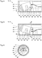
Figur 5 zeigt eine schematische Darstellung eines distalen Endes 14 eines Schafts 12 eines weiteren Endoskops 10, das in einigen Merkmalen, Eigenschaften und Funktionen dem anhand derFiguren 1 bis 4 dargestellten Endoskop ähnelt. Nachfolgend sind insbesondere Merkmale, Eigenschaften und Funktionen des inFigur 5 gezeigten Endoskops 10 beschrieben, in denen dieses sich von dem anhand derFiguren 1 bis 4 dargestellten Endoskop unterscheidet. Die Art der Darstellung inFigur 5 entspricht derjenigen derFiguren 2 bis 4 . - Das in
Figur 5 gezeigte Endoskop 10 unterscheidet sich von dem anhand derFiguren 1 bis 4 dargestellten Endoskop insbesondere durch eine andere Orientierung der Gleitflächen 64, 96 an Bilderfassungseinrichtung 50 und Antriebseinrichtung 90. Die Flächennormale 97 der Gleitfläche 96 am distalen Ende 92 der Antriebseinrichtung 90 ist radial zur Längsachse 38 des Schafts 12, die auch Rotationsachse der rotierbaren Antriebseinrichtung 90 ist, orientiert. Die Gleitfläche 64 am Gehäuse 60 der Bilderfassungseinrichtung 50 ist ein kreisringförmiger Ausschnitt aus einer Mantelfläche eines spitzen Kreiskegels. -
Figur 6 zeigt eine weitere schematische Darstellung des distalen Endes 14 des Schafts 12 des Endoskops 10 ausFigur 5 . InFigur 6 ist ein Schnitt entlang der inFigur 5 angedeuteten Ebene VI-VI orthogonal zu der Längsachse 38 des Schafts 12 gezeigt. Der Schaft 12 weist die Gestalt eines Rohrs mit kreisförmigem Querschnitt auf. Die Antriebseinrichtung 50 ist im Wesentlichen kreiszylindrisch und im Lumen des Schafts 12 spiel- und reibungsarm geführt. - Die Gleitfläche 96 ist an einer wie bereits in
Figur 5 erkennbar nach distal überstehenden Nase der Antriebseinrichtung 90 angeordnet. Das Gehäuse 60 der Bilderfassungseinrichtung 50 und die Gleitfläche 64 an dem Gehäuse 60 sind durch die Schnittebene VI-VI nur angeschnitten. Der vor der Schnittebene VI-VI liegende und deshalb an sich in der Darstellung inFigur 6 nicht sichtbare Abschnitt des Randes der Gleitfläche 64 ist inFigur 6 durch eine gestrichelte Linie angedeutet. Der distale Rand des als Kabelkanal für die Signalleitung 56 fungierenden Lumens 98 in der Antriebseinrichtung 90 ist hinter dem Gehäuse 60 der Bilderfassungseinrichtung 50 teilweise sichtbar. -
Figur 7 zeigt eine schematische Darstellung eines Schnitts durch einen Schaft 12 eines Endoskops, das in einigen Merkmalen, Eigenschaften und Funktionen dem anhand derFiguren 1 bis 4 dargestellten Endoskop und vor allem dem anhand derFiguren 5 und 6 dargestellten Endoskop ähnelt. Nachfolgend sind insbesondere Merkmale, Eigenschaften und Funktionen beschrieben, in denen das inFigur 7 gezeigte Endoskop sich von dem anhand derFiguren 5 und 6 dargestellten Endoskop unterscheidet. Die Art der Darstellung inFigur 7 , insbesondere die Orientierung und Lage der dargestellten Schnittebene, entspricht derjenigen derFigur 6 . - Das in
Figur 7 dargestellte Endoskop unterscheidet sich von dem anhand derFiguren 5 und 6 dargestellten Endoskop insbesondere dadurch, dass die Gleitfläche 96 am distalen Ende der Antriebseinrichtung 90 aus zwei voneinander beabstandeten Teilbereichen besteht. Diese beiden Teilbereiche der Gleitfläche 96 am distalen Ende der Antriebseinrichtung 90 berühren die Gleitflächen 64 am Gehäuse der Bilderfassungseinrichtung 50 an zwei voneinander beabstandeten Orten. An jeder der beiden Teilbereiche der Gleitfläche 96 ist die zugeordnete Flächennormale 97 orthogonal zur Längsachse des Schafts 12 und damit parallel zur Schnittebene derFigur 7 . - Auch bei dem anhand der
Figuren 1 bis 4 dargestellten Endoskop kann die Gleitfläche 96 am distalen Ende 92 der Antriebseinrichtung 90 aus zwei oder mehr voneinander beabstandeten Teilbereichen bestehen. -
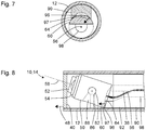
Fig. 8 zeigt eine schematische Darstellung eines distalen Endes 14 eines Schafts 12 eines weiteren Endoskops 10, das in einigen Merkmalen, Eigenschaften und Funktionen den anhand derFiguren 1 bis 7 dargestellten Endoskopen ähnelt. Nachfolgend sind insbesondere Merkmale, Eigenschaften und Funktionen beschrieben, in denen das inFigur 8 gezeigte Endoskop 10 sich von den anhand derFiguren 1 bis 7 dargestellten Endoskopen unterscheidet. Die Art der Darstellung inFigur 8 , insbesondere die Orientierung der Zeichenebene und die Lage und Orientierung der Schnittebene des Schafts 12, entspricht derjenigen derFiguren 2 bis 5 . - Das in
Figur 8 gezeigte Endoskop unterscheidet sich von den anhand derFiguren 1 bis 7 dargestellten Endoskopen insbesondere dadurch, dass die Gleitfläche 64 an dem Gehäuse 60 der Bilderfassungseinrichtung 50 im Wesentlichen nach proximal und die Gleitfläche 96 am distalen Ende 92 der Antriebseinrichtung 90 im Wesentlichen nach distal orientiert sind. Die Flächennormale 97 der Gleitfläche 96 am distalen Ende der Antriebseinrichtung 90 ist bei dem dargestellten Beispiel parallel zu der Längsachse 38 des Schafts 12. Die Gleitfläche 96 an dem distalen Ende 92 der Antriebseinrichtung 90 kann zwei oder mehr voneinander beabstandete Teilbereiche aufweisen, ähnlich wie bei dem anhand derFigur 7 dargestellten Beispiel. - Bei allen anhand der
Figuren 1 bis 8 dargestellten Endoskopen kann die Bilderfassungseinrichtung 50 zwei oder mehr nebeneinander angeordnete Objektive 52 und optional eine entsprechende Anzahl von Bildsensoren aufweisen, um ein Stereobild erfassen zu können. In diesem Fall kann das Kugelgelenk 62 in einem Bereich zwischen den Objektiven 52 oder zwischen den Bildsensoren 54 angeordnet sein. - Bei allen anhand der
Figuren 1 bis 8 dargestellten Endoskopen kann anstelle des Kugelgelenks 62 eine andere Schwenklagereinrichtung vorgesehen sein, beispielsweise in Gestalt einer kardanischen Aufhängung. -
- 10
- Endoskop
- 12
- Schaft des Endoskops 10
- 14
- distales Ende des Schafts 12
- 16
- proximales Ende des Schafts 12
- 18
- proximaler Bereich des Endoskops 10
- 19
- Drehrad als Bedienelement des Endoskops 10
- 38
- Längsachse des Schafts 12 und Rotationsachse der Antriebseinrichtung 90
- 40
- Fensterbauteil an dem distalen Ende 24 des Schafts 20
- 48
- Flächennormale des Fensterbauteils 40
- 50
- Bilderfassungseinrichtung des Endoskops 10
- 52
- Objektiv der Bilderfassungeinrichtung 50, zum Erzeugen eines reellen Bilds
- 54
- Bildsensor der Bilderfassungseinrichtung 50, zum Erfassen des von dem Objektiv 52 erzeugten reellen Bilds und zum Erzeugen eines Bildsignals
- 56
- Signalleitung zum Übertragen von Leistung und/oder eines Steuersignals zu dem Bildsensor 54 und/oder zum Übertragen des Bildsignals von dem Bildsensor 54
- 58
- optische Achse des Objektivs 52 und Blickrichtung der Bilderfassungseinrichtung 50
- 60
- Gehäuse der Bilderfassungseinrichtungen 50
- 62
- Schwenklagereinrichtung, insbesondere Kugelgelenk zwischen der Bilderfassungseinrichtung 50 und dem distalen Ende 14 des Schafts 12
- 64
- Gleitfläche an dem Gehäuse 60
- 86
- stabförmiges Bauteil, das das Schwenklager 62 mit dem Schaft 12 mechanisch starr verbindet
- 88
- Schlitz in dem Gehäuse 60, in dem das stabförmige Bauteil 86 angeordnet ist
- 90
- Antriebseinrichtung des Endoskops 10
- 92
- distales Ende der Antriebseinrichtung 90
- 96
- Gleitfläche an dem distalen Ende 92 der Antriebseinrichtung 90
- 97
- Flächennormale der Gleitfläche 96
- 98
- Lumen der Antriebseinrichtung 90
Claims (15)
- Endoskop (10) mit:einer Bilderfassungseinrichtung (50) mit einem Objektiv (52) zum Erzeugen eines reellen Bilds und einem Bildsensor (54) zum Erfassen des reellen Bilds und zum Erzeugen eines Bildsignals, das das erfasste reelle Bild repräsentiert;einer Schwenklagereinrichtung (62), die ein Bewegen der optischen Achse (58) des Objektivs (52) der Bilderfassungseinrichtung (50) auf einem Kegelmantel ermöglicht;einer um eine Rotationsachse (38) rotierbaren Antriebseinrichtung (90),wobei die rotierbare Antriebseinrichtung (90) derart mit der Bilderfassungseinrichtung (50) mechanisch gekoppelt ist, dass eine Rotation der rotierbaren Antriebseinrichtung (90) mit einem Bewegen der optischen Achse (58) des Objektivs (54) der Bilderfassungseinrichtung (50) auf einem Kegelmantel einher geht.
- Endoskop (10) nach dem vorangehenden Anspruch, bei dem ein distales Ende (92) der Antriebseinrichtung (90) zumindest entweder proximal der Schwenklagereinrichtung (62) oder proximal der Bilderfassungseinrichtung (50) angeordnet ist.
- Endoskop (10) nach einem der vorangehenden Ansprüche, bei dem die Antriebseinrichtung (90) kein Zahnrad, kein Kurvengetriebe und keine Schnecke aufweist.
- Endoskop (10) nach einem der vorangehenden Ansprüche, bei dem die Schwenklagereinrichtung (62) ein Schwenken um eine erste Schwenkachse orthogonal oder im Wesentlichen othogonal zu einer Symmetrieachse des Kegelmantels und ein Schwenken um eine zweite Schwenkachse orthogonal oder im Wesentlichen orthogonal zu der ersten Schwenkachse und orthogonal oder im Wesentlichen orthogonal zu der Symmetrieachse des Kegelmantels ermöglicht.
- Endoskop (10) nach einem der vorangehenden Ansprüche, ferner mit:
einer Führungseinrichtung (86, 88), die eine vorbestimmte Reihe von Pixeln des Bildsensors (54) in jeder Position der Bilderfassungseinrichtung (50) parallel zu einer vorbestimmten Ebene hält. - Endoskop (10) nach einem der vorangehenden Ansprüche, bei dem die Schwenklagereinrichtung ein Kugelgelenk (62), ein stabförmiges Bauteil (86), an dessen Ende das Kugelgelenk (62) angeordnet ist, und einen Schlitz (88), in dem das stabförmige Bauteil (86) spiel- und reibungsarm schwenkbar geführt ist, umfasst.
- Endoskop (10) nach einem der vorangehenden Ansprüche, ferner mit:einer ersten Gleitfläche (64), die mit der Bilderfassungseinrichtung (50) mechanisch starr verbunden ist;einer zweiten Gleitfläche (96) an einem distalen Ende (92) der rotierbaren Antriebseinrichtung (90), die an der ersten Gleitfläche (96) anliegt.
- Endoskop (10) nach dem vorangehenden Anspruch, bei dem die erste Gleitfläche (64) kreisbogenförmig oder kreisringförmig ist.
- Endoskop (10) nach einem der Ansprüche 7 und 8, bei dem die erste Gleitfläche (64) rotationssymmetrisch zur Blickrichtung (58) der Bilderfassungseinrichtung (50) ist.
- Endoskop (10) nach einem der Ansprüche 7 bis 9, bei dem die zweite Gleitfläche (96) zwei von einander beabstandete Teilflächen umfasst.
- Endoskop (10) nach einem Ansprüche 7 bis 10, bei dem die erste Gleitfläche (64) nach proximal und die zweite Gleitfläche (96) nach distal orientiert sind.
- Endoskop (10) nach einem Ansprüche 7 bis 11, bei dem eine Flächennormale der zweiten Gleitfläche (96) zu einer Rotationsachse (38) der rotierbaren Antriebseinrichtung (90) hin orientiert ist.
- Endoskop (10) nach einem der vorangehenden Ansprüche, wobei
zwei gleiche oder ähnliche Bilderfassungseinrichtungen (50) nebeneinander angeordnet und miteinander mechanisch starr verbunden sind. - Endoskop (10) nach dem vorangehenden Anspruch, bei dem die Schwenklagereinrichtung ein Kugelgelenk (62) umfasst, das zwischen den Bilderfassungseinrichtungen (50) angeordnet ist.
- Endoskop (10) nach einem der vorangehenden Ansprüche, ferner mit:einem Schaft (12) mit einem proximalen Ende (16) und einem distalen Ende (14) zum Einführen in einen Hohlraum,einer Signalleitung (56) zumindest entweder zum Übertragen eines Steuersignals von dem proximalen Ende (16) des Schafts (12) zu der Bilderfassungseinrichtung (50) oder zum Übertragen eines Bildsignals von der Bilderfassungseinrichtung (50) zu dem proximalen Ende (16) des Schafts (12),wobei die rotierbare Antriebseinrichtung (90) als Rohr ausgebildet ist,wobei die Signalleitung (56) innerhalb eines Lumens der rotierbaren Antriebseinrichtung (90) angeordnet ist.
Applications Claiming Priority (1)
| Application Number | Priority Date | Filing Date | Title |
|---|---|---|---|
| DE102020115257.4A DE102020115257B3 (de) | 2020-06-09 | 2020-06-09 | Endoskop mit schwenkbarer Bilderfassungseinrichtung |
Publications (2)
| Publication Number | Publication Date |
|---|---|
| EP3922161A1 true EP3922161A1 (de) | 2021-12-15 |
| EP3922161B1 EP3922161B1 (de) | 2025-10-29 |
Family
ID=76181032
Family Applications (1)
| Application Number | Title | Priority Date | Filing Date |
|---|---|---|---|
| EP21176684.5A Active EP3922161B1 (de) | 2020-06-09 | 2021-05-28 | Endoskop mit schwenkbarer bilderfassungseinrichtung |
Country Status (2)
| Country | Link |
|---|---|
| EP (1) | EP3922161B1 (de) |
| DE (1) | DE102020115257B3 (de) |
Citations (12)
| Publication number | Priority date | Publication date | Assignee | Title |
|---|---|---|---|---|
| US20070055103A1 (en) | 2005-08-31 | 2007-03-08 | Siegfried Hoefig | Endoscope with variable direction of view |
| US20110115882A1 (en) * | 2009-11-13 | 2011-05-19 | Hrayr Karnig Shahinian | Stereo imaging miniature endoscope with single imaging chip and conjugated multi-bandpass filters |
| DE102010028147A1 (de) * | 2010-04-23 | 2011-10-27 | Olympus Winter & Ibe Gmbh | Endoskop mit variabler Blickrichtung |
| DE102012206963A1 (de) | 2011-04-26 | 2012-10-31 | Otto-Von-Guericke-Universität Magdeburg Medizinische Fakultät | Endoskop |
| US20130182091A1 (en) | 2010-10-05 | 2013-07-18 | Panasonic Corporation | Endoscope |
| US20150359420A1 (en) | 2014-06-11 | 2015-12-17 | Panasonic Intellectual Property Management Co., Ltd. | Endoscope and method of manufacturing endoscope |
| EP3243426A1 (de) | 2016-05-13 | 2017-11-15 | Karl Storz Endovision, Inc. | Optisches instrument und gelenkige bildaufnahmevorrichtung dafür |
| WO2018065241A1 (de) | 2016-10-04 | 2018-04-12 | Olympus Winter & Ibe Gmbh | Winkelselektives optisches system, stereo-videoendoskop mit einem solchen system sowie verfahren zum herstellen desselben |
| DE102017103721A1 (de) | 2017-02-23 | 2018-08-23 | Karl Storz Se & Co. Kg | Vorrichtung zur Erfassung eines Stereobilds |
| US20180344288A1 (en) * | 2011-10-31 | 2018-12-06 | Volcano Corporation | Devices, systems, and methods for controlling field of view in imaging systems |
| US20190117044A1 (en) * | 2017-10-25 | 2019-04-25 | Boston Scientific Scimed Inc. | Direct visualization catheter and system |
| US20190274526A1 (en) | 2016-12-07 | 2019-09-12 | Olympus Corporation | Stereoscopic image pickup apparatus and stereoscopic endoscope |
-
2020
- 2020-06-09 DE DE102020115257.4A patent/DE102020115257B3/de active Active
-
2021
- 2021-05-28 EP EP21176684.5A patent/EP3922161B1/de active Active
Patent Citations (12)
| Publication number | Priority date | Publication date | Assignee | Title |
|---|---|---|---|---|
| US20070055103A1 (en) | 2005-08-31 | 2007-03-08 | Siegfried Hoefig | Endoscope with variable direction of view |
| US20110115882A1 (en) * | 2009-11-13 | 2011-05-19 | Hrayr Karnig Shahinian | Stereo imaging miniature endoscope with single imaging chip and conjugated multi-bandpass filters |
| DE102010028147A1 (de) * | 2010-04-23 | 2011-10-27 | Olympus Winter & Ibe Gmbh | Endoskop mit variabler Blickrichtung |
| US20130182091A1 (en) | 2010-10-05 | 2013-07-18 | Panasonic Corporation | Endoscope |
| DE102012206963A1 (de) | 2011-04-26 | 2012-10-31 | Otto-Von-Guericke-Universität Magdeburg Medizinische Fakultät | Endoskop |
| US20180344288A1 (en) * | 2011-10-31 | 2018-12-06 | Volcano Corporation | Devices, systems, and methods for controlling field of view in imaging systems |
| US20150359420A1 (en) | 2014-06-11 | 2015-12-17 | Panasonic Intellectual Property Management Co., Ltd. | Endoscope and method of manufacturing endoscope |
| EP3243426A1 (de) | 2016-05-13 | 2017-11-15 | Karl Storz Endovision, Inc. | Optisches instrument und gelenkige bildaufnahmevorrichtung dafür |
| WO2018065241A1 (de) | 2016-10-04 | 2018-04-12 | Olympus Winter & Ibe Gmbh | Winkelselektives optisches system, stereo-videoendoskop mit einem solchen system sowie verfahren zum herstellen desselben |
| US20190274526A1 (en) | 2016-12-07 | 2019-09-12 | Olympus Corporation | Stereoscopic image pickup apparatus and stereoscopic endoscope |
| DE102017103721A1 (de) | 2017-02-23 | 2018-08-23 | Karl Storz Se & Co. Kg | Vorrichtung zur Erfassung eines Stereobilds |
| US20190117044A1 (en) * | 2017-10-25 | 2019-04-25 | Boston Scientific Scimed Inc. | Direct visualization catheter and system |
Also Published As
| Publication number | Publication date |
|---|---|
| EP3922161B1 (de) | 2025-10-29 |
| DE102020115257B3 (de) | 2021-10-07 |
Similar Documents
| Publication | Publication Date | Title |
|---|---|---|
| DE60203242T2 (de) | Verdrehbare Endoskope mit abgewinkeltem Distalvisier | |
| DE3921233C2 (de) | ||
| DE10004264C2 (de) | Vorrichtung zur intrakorporalen, minimal-invasiven Behandlung eines Patienten | |
| EP3922162B1 (de) | Endoskop mit schwenkbarer bilderfassungseinrichtung | |
| DE102009049143B3 (de) | Endoskop | |
| EP2838414B1 (de) | Rotationsvorrichtung zum rotieren eines endoskops | |
| DE4422522B4 (de) | Beobachtungs- und/oder Dokumentationseinrichtung mit vorgeschaltetem Endoskop sowie Verfahren zu deren Betrieb | |
| EP1600804A1 (de) | Visuelle Einrichtung eines Endoskops | |
| DE102010041857A1 (de) | Stereoendoskop | |
| DE102017103721B4 (de) | Vorrichtung zur Erfassung eines Stereobilds mit einer rotierbaren Blickrichtungseinrichtung | |
| DE19609034A1 (de) | Vorrichtung zur Führung chirurgischer Instrumente für die endoskopische Chirurgie | |
| DE102010022430A1 (de) | Sichtfeldvorrichtung für ein Endoskop | |
| EP2514353A1 (de) | Endoskop mit variabler Blickrichtung | |
| WO2015014481A1 (de) | Robotersystem | |
| DE4241938B4 (de) | Endoskop insbesondere mit Stereo-Seitblickoptik | |
| DE19942152B4 (de) | Endoskop | |
| DE102016212470A1 (de) | Optisches System eines Stereo-Videoendoskops, Stereo-Videoendoskop und Verfahren zum Betreiben eines optischen Systems eines Stereo-Videoendoskops | |
| DE102010041847A1 (de) | Sensoreinheit für ein Stereoendoskop und Stereoendoskopiesystem | |
| DE102010028147A1 (de) | Endoskop mit variabler Blickrichtung | |
| DE102020100677B3 (de) | Optisches Beobachtungsinstrument | |
| DE10222505A1 (de) | Mikroendoskop | |
| DE4304422C1 (de) | Endoskop | |
| DE102010007394A1 (de) | Medizinisches Instrument mit einem magnetischen Stelltrieb | |
| DE102020115257B3 (de) | Endoskop mit schwenkbarer Bilderfassungseinrichtung | |
| WO2022078558A1 (de) | Verfahren zur wiedergabe eines mittels eines 3d-endoskops erzeugten stereoskopischen bildes und 3d-endoskop |
Legal Events
| Date | Code | Title | Description |
|---|---|---|---|
| PUAI | Public reference made under article 153(3) epc to a published international application that has entered the european phase |
Free format text: ORIGINAL CODE: 0009012 |
|
| STAA | Information on the status of an ep patent application or granted ep patent |
Free format text: STATUS: THE APPLICATION HAS BEEN PUBLISHED |
|
| AK | Designated contracting states |
Kind code of ref document: A1 Designated state(s): AL AT BE BG CH CY CZ DE DK EE ES FI FR GB GR HR HU IE IS IT LI LT LU LV MC MK MT NL NO PL PT RO RS SE SI SK SM TR |
|
| B565 | Issuance of search results under rule 164(2) epc |
Effective date: 20211022 |
|
| STAA | Information on the status of an ep patent application or granted ep patent |
Free format text: STATUS: REQUEST FOR EXAMINATION WAS MADE |
|
| 17P | Request for examination filed |
Effective date: 20220609 |
|
| RBV | Designated contracting states (corrected) |
Designated state(s): AL AT BE BG CH CY CZ DE DK EE ES FI FR GB GR HR HU IE IS IT LI LT LU LV MC MK MT NL NO PL PT RO RS SE SI SK SM TR |
|
| STAA | Information on the status of an ep patent application or granted ep patent |
Free format text: STATUS: EXAMINATION IS IN PROGRESS |
|
| 17Q | First examination report despatched |
Effective date: 20230503 |
|
| P01 | Opt-out of the competence of the unified patent court (upc) registered |
Effective date: 20230527 |
|
| GRAP | Despatch of communication of intention to grant a patent |
Free format text: ORIGINAL CODE: EPIDOSNIGR1 |
|
| STAA | Information on the status of an ep patent application or granted ep patent |
Free format text: STATUS: GRANT OF PATENT IS INTENDED |
|
| INTG | Intention to grant announced |
Effective date: 20250528 |
|
| GRAS | Grant fee paid |
Free format text: ORIGINAL CODE: EPIDOSNIGR3 |
|
| GRAA | (expected) grant |
Free format text: ORIGINAL CODE: 0009210 |
|
| STAA | Information on the status of an ep patent application or granted ep patent |
Free format text: STATUS: THE PATENT HAS BEEN GRANTED |
|
| AK | Designated contracting states |
Kind code of ref document: B1 Designated state(s): AL AT BE BG CH CY CZ DE DK EE ES FI FR GB GR HR HU IE IS IT LI LT LU LV MC MK MT NL NO PL PT RO RS SE SI SK SM TR |
|
| REG | Reference to a national code |
Ref country code: CH Ref legal event code: F10 Free format text: ST27 STATUS EVENT CODE: U-0-0-F10-F00 (AS PROVIDED BY THE NATIONAL OFFICE) Effective date: 20251029 Ref country code: GB Ref legal event code: FG4D Free format text: NOT ENGLISH |
|
| REG | Reference to a national code |
Ref country code: DE Ref legal event code: R096 Ref document number: 502021009060 Country of ref document: DE |
|
| REG | Reference to a national code |
Ref country code: IE Ref legal event code: FG4D Free format text: LANGUAGE OF EP DOCUMENT: GERMAN |
|
| REG | Reference to a national code |
Ref country code: NL Ref legal event code: MP Effective date: 20251029 |
|
| PGFP | Annual fee paid to national office [announced via postgrant information from national office to epo] |
Ref country code: GB Payment date: 20260313 Year of fee payment: 6 |
|
| PG25 | Lapsed in a contracting state [announced via postgrant information from national office to epo] |
Ref country code: ES Free format text: LAPSE BECAUSE OF FAILURE TO SUBMIT A TRANSLATION OF THE DESCRIPTION OR TO PAY THE FEE WITHIN THE PRESCRIBED TIME-LIMIT Effective date: 20251029 |
|
| REG | Reference to a national code |
Ref country code: LT Ref legal event code: MG9D |
|
| PG25 | Lapsed in a contracting state [announced via postgrant information from national office to epo] |
Ref country code: NO Free format text: LAPSE BECAUSE OF FAILURE TO SUBMIT A TRANSLATION OF THE DESCRIPTION OR TO PAY THE FEE WITHIN THE PRESCRIBED TIME-LIMIT Effective date: 20260129 |
|
| PG25 | Lapsed in a contracting state [announced via postgrant information from national office to epo] |
Ref country code: HR Free format text: LAPSE BECAUSE OF FAILURE TO SUBMIT A TRANSLATION OF THE DESCRIPTION OR TO PAY THE FEE WITHIN THE PRESCRIBED TIME-LIMIT Effective date: 20251029 Ref country code: FI Free format text: LAPSE BECAUSE OF FAILURE TO SUBMIT A TRANSLATION OF THE DESCRIPTION OR TO PAY THE FEE WITHIN THE PRESCRIBED TIME-LIMIT Effective date: 20251029 |
|
| PG25 | Lapsed in a contracting state [announced via postgrant information from national office to epo] |
Ref country code: NL Free format text: LAPSE BECAUSE OF FAILURE TO SUBMIT A TRANSLATION OF THE DESCRIPTION OR TO PAY THE FEE WITHIN THE PRESCRIBED TIME-LIMIT Effective date: 20251029 |
|
| PG25 | Lapsed in a contracting state [announced via postgrant information from national office to epo] |
Ref country code: RS Free format text: LAPSE BECAUSE OF FAILURE TO SUBMIT A TRANSLATION OF THE DESCRIPTION OR TO PAY THE FEE WITHIN THE PRESCRIBED TIME-LIMIT Effective date: 20260129 |
|
| PG25 | Lapsed in a contracting state [announced via postgrant information from national office to epo] |
Ref country code: IS Free format text: LAPSE BECAUSE OF FAILURE TO SUBMIT A TRANSLATION OF THE DESCRIPTION OR TO PAY THE FEE WITHIN THE PRESCRIBED TIME-LIMIT Effective date: 20260228 |
|
| PG25 | Lapsed in a contracting state [announced via postgrant information from national office to epo] |
Ref country code: PT Free format text: LAPSE BECAUSE OF FAILURE TO SUBMIT A TRANSLATION OF THE DESCRIPTION OR TO PAY THE FEE WITHIN THE PRESCRIBED TIME-LIMIT Effective date: 20260302 |
|
| PG25 | Lapsed in a contracting state [announced via postgrant information from national office to epo] |
Ref country code: PL Free format text: LAPSE BECAUSE OF FAILURE TO SUBMIT A TRANSLATION OF THE DESCRIPTION OR TO PAY THE FEE WITHIN THE PRESCRIBED TIME-LIMIT Effective date: 20251029 |
|
| PG25 | Lapsed in a contracting state [announced via postgrant information from national office to epo] |
Ref country code: LV Free format text: LAPSE BECAUSE OF FAILURE TO SUBMIT A TRANSLATION OF THE DESCRIPTION OR TO PAY THE FEE WITHIN THE PRESCRIBED TIME-LIMIT Effective date: 20251029 |
|
| PG25 | Lapsed in a contracting state [announced via postgrant information from national office to epo] |
Ref country code: BG Free format text: LAPSE BECAUSE OF FAILURE TO SUBMIT A TRANSLATION OF THE DESCRIPTION OR TO PAY THE FEE WITHIN THE PRESCRIBED TIME-LIMIT Effective date: 20251029 |