EP3920815B1 - Lighted cannula system - Google Patents
Lighted cannula system Download PDFInfo
- Publication number
- EP3920815B1 EP3920815B1 EP20752885.2A EP20752885A EP3920815B1 EP 3920815 B1 EP3920815 B1 EP 3920815B1 EP 20752885 A EP20752885 A EP 20752885A EP 3920815 B1 EP3920815 B1 EP 3920815B1
- Authority
- EP
- European Patent Office
- Prior art keywords
- cannula
- cannula tube
- proximal end
- tube
- lights
- Prior art date
- Legal status (The legal status is an assumption and is not a legal conclusion. Google has not performed a legal analysis and makes no representation as to the accuracy of the status listed.)
- Active
Links
Images

Classifications
-
- A—HUMAN NECESSITIES
- A61—MEDICAL OR VETERINARY SCIENCE; HYGIENE
- A61B—DIAGNOSIS; SURGERY; IDENTIFICATION
- A61B17/00—Surgical instruments, devices or methods
- A61B17/34—Trocars; Puncturing needles
- A61B17/3417—Details of tips or shafts, e.g. grooves, expandable, bendable; Multiple coaxial sliding cannulas, e.g. for dilating
- A61B17/3421—Cannulas
-
- A—HUMAN NECESSITIES
- A61—MEDICAL OR VETERINARY SCIENCE; HYGIENE
- A61B—DIAGNOSIS; SURGERY; IDENTIFICATION
- A61B1/00—Instruments for performing medical examinations of the interior of cavities or tubes of the body by visual or photographical inspection, e.g. endoscopes; Illuminating arrangements therefor
- A61B1/06—Instruments for performing medical examinations of the interior of cavities or tubes of the body by visual or photographical inspection, e.g. endoscopes; Illuminating arrangements therefor with illuminating arrangements
- A61B1/0661—Endoscope light sources
- A61B1/0669—Endoscope light sources at proximal end of an endoscope
-
- A—HUMAN NECESSITIES
- A61—MEDICAL OR VETERINARY SCIENCE; HYGIENE
- A61B—DIAGNOSIS; SURGERY; IDENTIFICATION
- A61B1/00—Instruments for performing medical examinations of the interior of cavities or tubes of the body by visual or photographical inspection, e.g. endoscopes; Illuminating arrangements therefor
- A61B1/04—Instruments for performing medical examinations of the interior of cavities or tubes of the body by visual or photographical inspection, e.g. endoscopes; Illuminating arrangements therefor combined with photographic or television appliances
- A61B1/042—Instruments for performing medical examinations of the interior of cavities or tubes of the body by visual or photographical inspection, e.g. endoscopes; Illuminating arrangements therefor combined with photographic or television appliances characterised by a proximal camera, e.g. a CCD camera
-
- A—HUMAN NECESSITIES
- A61—MEDICAL OR VETERINARY SCIENCE; HYGIENE
- A61B—DIAGNOSIS; SURGERY; IDENTIFICATION
- A61B1/00—Instruments for performing medical examinations of the interior of cavities or tubes of the body by visual or photographical inspection, e.g. endoscopes; Illuminating arrangements therefor
- A61B1/06—Instruments for performing medical examinations of the interior of cavities or tubes of the body by visual or photographical inspection, e.g. endoscopes; Illuminating arrangements therefor with illuminating arrangements
- A61B1/0607—Instruments for performing medical examinations of the interior of cavities or tubes of the body by visual or photographical inspection, e.g. endoscopes; Illuminating arrangements therefor with illuminating arrangements for annular illumination
-
- A—HUMAN NECESSITIES
- A61—MEDICAL OR VETERINARY SCIENCE; HYGIENE
- A61B—DIAGNOSIS; SURGERY; IDENTIFICATION
- A61B1/00—Instruments for performing medical examinations of the interior of cavities or tubes of the body by visual or photographical inspection, e.g. endoscopes; Illuminating arrangements therefor
- A61B1/06—Instruments for performing medical examinations of the interior of cavities or tubes of the body by visual or photographical inspection, e.g. endoscopes; Illuminating arrangements therefor with illuminating arrangements
- A61B1/0661—Endoscope light sources
- A61B1/0684—Endoscope light sources using light emitting diodes [LED]
-
- A—HUMAN NECESSITIES
- A61—MEDICAL OR VETERINARY SCIENCE; HYGIENE
- A61B—DIAGNOSIS; SURGERY; IDENTIFICATION
- A61B1/00—Instruments for performing medical examinations of the interior of cavities or tubes of the body by visual or photographical inspection, e.g. endoscopes; Illuminating arrangements therefor
- A61B1/313—Instruments for performing medical examinations of the interior of cavities or tubes of the body by visual or photographical inspection, e.g. endoscopes; Illuminating arrangements therefor for introducing through surgical openings, e.g. laparoscopes
-
- A—HUMAN NECESSITIES
- A61—MEDICAL OR VETERINARY SCIENCE; HYGIENE
- A61B—DIAGNOSIS; SURGERY; IDENTIFICATION
- A61B17/00—Surgical instruments, devices or methods
- A61B17/00234—Surgical instruments, devices or methods for minimally invasive surgery
-
- A—HUMAN NECESSITIES
- A61—MEDICAL OR VETERINARY SCIENCE; HYGIENE
- A61B—DIAGNOSIS; SURGERY; IDENTIFICATION
- A61B17/00—Surgical instruments, devices or methods
- A61B17/34—Trocars; Puncturing needles
- A61B17/3417—Details of tips or shafts, e.g. grooves, expandable, bendable; Multiple coaxial sliding cannulas, e.g. for dilating
- A61B17/3421—Cannulas
- A61B17/3423—Access ports, e.g. toroid shape introducers for instruments or hands
-
- A—HUMAN NECESSITIES
- A61—MEDICAL OR VETERINARY SCIENCE; HYGIENE
- A61B—DIAGNOSIS; SURGERY; IDENTIFICATION
- A61B90/00—Instruments, implements or accessories specially adapted for surgery or diagnosis and not covered by any of the groups A61B1/00 - A61B50/00, e.g. for luxation treatment or for protecting wound edges
- A61B90/30—Devices for illuminating a surgical field, the devices having an interrelation with other surgical devices or with a surgical procedure
-
- A—HUMAN NECESSITIES
- A61—MEDICAL OR VETERINARY SCIENCE; HYGIENE
- A61L—METHODS OR APPARATUS FOR STERILISING MATERIALS OR OBJECTS IN GENERAL; DISINFECTION, STERILISATION OR DEODORISATION OF AIR; CHEMICAL ASPECTS OF BANDAGES, DRESSINGS, ABSORBENT PADS OR SURGICAL ARTICLES; MATERIALS FOR BANDAGES, DRESSINGS, ABSORBENT PADS OR SURGICAL ARTICLES
- A61L29/00—Materials for catheters, medical tubing, cannulae, or endoscopes or for coating catheters
- A61L29/02—Inorganic materials
-
- A—HUMAN NECESSITIES
- A61—MEDICAL OR VETERINARY SCIENCE; HYGIENE
- A61B—DIAGNOSIS; SURGERY; IDENTIFICATION
- A61B17/00—Surgical instruments, devices or methods
- A61B2017/00831—Material properties
- A61B2017/00902—Material properties transparent or translucent
- A61B2017/00907—Material properties transparent or translucent for light
-
- A—HUMAN NECESSITIES
- A61—MEDICAL OR VETERINARY SCIENCE; HYGIENE
- A61B—DIAGNOSIS; SURGERY; IDENTIFICATION
- A61B90/00—Instruments, implements or accessories specially adapted for surgery or diagnosis and not covered by any of the groups A61B1/00 - A61B50/00, e.g. for luxation treatment or for protecting wound edges
- A61B90/30—Devices for illuminating a surgical field, the devices having an interrelation with other surgical devices or with a surgical procedure
- A61B2090/309—Devices for illuminating a surgical field, the devices having an interrelation with other surgical devices or with a surgical procedure using white LEDs
Definitions
- the inventions described below relate to the field of cannula systems for minimally invasive brain or spine surgery.
- U.S. Patent 10,172,525 discloses a cannula and proximally mounted camera system for improved visualization of the brain during minimally invasive surgery.
- the system includes a cannula with a camera mounted on the proximal end of the cannula with a view into the cannula lumen and the tissue within and below the lumen, along with a prism, reflector or other suitable optical element oriented between the camera and the lumen of the cannula to afford the camera a view into the cannula while minimizing obstruction of the lumen.
- Lighting disclosed in this patent included lights in the cannula to illuminate the distal end of the cannula or tissue near the distal end of the cannula, or light sources provided outside the assembly, or from lights mounted on the proximal end of the cannula.
- US 2007/0100210 discloses a lighted cannula that uses a light source in the form of a large light box remote from the cannula and connected via a lengthy fiber optic cable to a light-distributing ring on the proximal end of a cannula. The ring is configured to provide even, circumferential light about the interior of the cannula.
- US2007/276191 also uses a light source in the form of a large light box remote from the cannula and connected via a lengthy fiber optic cable to numerous optical fibers that run through the wall of the cannula to emit light at the distal end of the cannula.
- WO 2015/101624 discloses a lighted cannula in the form of a light guide, in which the wall of the cannula must be transparent, and the surfaces must have a specular finish to promote total internal reflectance necessary for the cannula to function as a light guide.
- WO 2015/101624 also uses a light source in the form of a light box, remote from the cannula and connected via a lengthy fiber optic cable to a light distributing ring about the proximal end of the cannula.
- the invention is defined by independent claim 1. Further embodiments are defined in the dependent claims.
- the devices and methods described below provide for improved lighting and/or reduced lighting requirements for cannulas used for minimally invasive surgery.
- a cannula suitable for use in minimally invasive surgery is improved with a highly polished and very smooth luminal wall and/or LED's or other light sources focused at particular angles relative to the axis of the cannula.
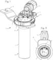
- Figure 1 illustrates a cannula system 1 for accessing a target site in the body of a patient.
- the cannula system comprises a cannula tube 2 and a lighting assembly 3 disposed proximate the proximal end 2p of the cannula tube.
- the lighting assembly 3 comprises a housing 4 with a number of lights 5 (LED's, incandescent bulbs, etc.).
- the lighting assembly may be mounted on a ring, or partial ring 6 as illustrated, and may be permanently fixed or releasably attachable to the proximal end 2p of the cannula tube, through releasable attachment means such as a C-ring expandable to engage a groove in the proximal end outer surface, or with an annular snap ring, or with screw threads or other easily attachable and detachable mechanisms.
- the lighting assembly may instead be directly fixed to the proximal end of the cannula tube or fixed on the ring 18 which in turn is fixed to the cannula tube (as shown in Figure 5 through 8 ).
- the cannula tube is characterized by a distal end 2d and a proximal end 2p, and a lumen 7 extending from the proximal end to the distal end, a central longitudinal axis 2L defined by the lumen, and a luminal surface 8 on the inner wall of the cannula tube.
- the cannula tube most conveniently has a circular radial cross section, but the radial cross section may be varied to provide for access to particular surgical sites.
- the cannula tube may consist of an opaque material, non-transmissive to visible light, such as metal, or it may comprise an opaque construction including a luminal surface comprising an opaque material which is non-transmissive to visible light in a cannula tube of transmissive or non-transmissive material (for example, an acrylic tube with a metallic coating).
- the lighting assembly 3 is disposed proximate the proximal end of the cannula tube, and is configured to hold light 5 proximal to the proximal opening of the cannula tube (this is preferable, but the lights may extend slightly distally into the lumen) to project light into the lumen of the cannula tube.
- the cannula tube may consist of an opaque material, non-transmissive to visible light, and is preferably made of metal such as stainless steel or aluminum.
- the effectiveness of the lighting is preferably enhanced by providing a very smooth surface on the inner wall of the cannula tube.
- the luminal surface is highly polished/smooth with an Average Roughness of 8 microinches or smoother (8 -6 inches, equivalent to Ra (um) 0.2 (0.2 microns), USA #8 finish, Japan Buff #300, or ISO N4 or smoother), to enhance the transmission of light from the proximal end of the cannula to the distal end of the cannula and a target site beyond the distal end of the cannula.
- the lights of Figure 1 may have a total output of 200 to 700 lumens, which, in combination with the smooth luminal surface, will provide in ample light at a surgical workspace at the distal end of the cannula tube. Combinations of slightly rougher surfaces with higher power lights may be used.
- the luminal surface may be provided in a Average Roughness in the range of 9 to 32 micro-inches (between 0.22 to 0.81 micrometers, ISO N5 or N6 finish, #6 or #7 finish (roughly), Japan Buff #100 or smoother) and the lights may be chosen to provide additional lumens, in the higher end of the range.
- the luminal surface may be provided in a Average Roughness in the range of 33 to 63 micro-inches (0.82 to 1.6 micrometers, ISO N7 finish, USA #3 or #4 finish) and the lights may be chosen to provide additional lumens, in the higher end of the range.
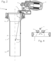
- the light 5 are characterized by a main beam axis 9, which may be directed at an angle ⁇ 1 of 70° to 85°, though preferably about 80° downward (distally) from the radial axis 2R, or, comparably, directed at an angle ⁇ 1 or 5° to 15° , and preferably about 10°, inward relative to the long axis 2L of the cannula tube, directed distally, in this embodiment where the cannula has a distal portion with a straight inner bore (of consistent diameter throughout the length of the distal portion) and a proximal conical section with a conical bore which is larger than the diameter of the straight inner bore at the proximal end of the proximal conical section and necks down to match the diameter of the straight inner bore of the straight distal portion.
- a main beam axis 9 which may be directed at an angle ⁇ 1 of 70° to 85°, though preferably about 80° downward (distally) from the radial axis 2R, or
- the lights are characterized by a main beam axis 9, which may be directed at an angle ⁇ 1 of 80° from the radial axis 2R, directed distally, or at an angle ⁇ 1 of 10° relative to the luminal surface of the cannula tube (toward the center of the lumen).
- Figures 1 and 2 illustrate the system with a cannula tube having a conical lumen in a proximal portion of the cannula tube
- the cannula tube may be isodiametric throughout its length, having a consistent or uniform inner diameter and straight luminal walls from the proximal end to the distal end, without a conical portion or a neckdown portion.
- Figure 3 is a view of the cannula system from the bottom, or distal end of the cannula tube.
- the beam axis 9 may be aimed to intersect the central axis 2C of the cannula tube, or the beam axis may be aimed at angle ⁇ from the radian 2R (the line between the LED and the central axis 2C, or, along a chord of the circle defined by the cannula tube). This angle is preferably in the range of about 10 to 30°.
- the light source may consist of only two LED's disposed over (proximal to) the proximal end of the cannula tube, either directly or on the ring 6 and separated by a first arc ⁇ 2 of 50° to 70°, and preferably about 60° as shown in Figure 3 (or, conversely, the second arc ⁇ 2 of 290° to 310°, and preferably about 300° as shown in Figure 3 ).
- the light source may consist of two pairs of closely spaced lights, with the pairs similarly separated.
- the lights and any associated lenses are disposed proximal to the proximal opening of the cannula tube without extending distally into the lumen.
- the proximal end of the cannula tube has an inner bore/lumen that is conical, with a proximal opening slightly larger than the diameter of the distal portion of the cannular tube.
- the cannula system may include a camera assembly 10 secured to the proximal end of the cannula, with a portion of the camera assembly overhanging the lumen and extending into a cylindrical space defined by the lumen of the cannula tube.
- the camera assembly has a distalmost optical surface, which may be a distal surface of an objective lens or a prism (the prism 11 is shown in Figure 2 , and the distal-most optical surface 12 is visible in the distal view of Figure 3 ), and the distal-most optical surface is disposed proximate the proximal end of the cannula tube.
- the objective lens or prism may be the portion of the camera assembly overhanging the lumen.
- the distal-most optical surface of the camera system is spaced proximally from the proximal end of the cannula tube in the illustration, but may be placed a short distance distal to the very proximal edge of the cannula tube (without extending to the distal end of the cannula tube).
- the cannula system can include a tab 13 for securing the cannula to a table-fixed flex arm.
- the distal most optical surface of the camera assembly is disposed between the lights, in the smaller arc ⁇ 2 separating the two lights.
- a gap in the housing, between the two lights (or two pairs of lights), provides an unobstructed sight-line between the distal-most optical surface and the workspace at the distal end of the cannula tube, and the distal most optical surface of the camera assembly is disposed within this gap or proximal to the gap.
- Figure 5 illustrates a second version of the cannula system for accessing a target site in the body of a patient.
- the cannula system 14 of Figure 5 comprises a cannula tube 15 and a lighting assembly 16 disposed proximate the proximal end of the cannula tube.
- the lighting assembly 16 comprises a number of lights 17 (LED's, incandescent bulbs, etc.) mounted on a ring 18 as illustrated (though a partial ring may be used, or the ring may be omitted), and may be permanently fixed or releasably attachable to the proximal end of the cannula tube, through releasable attachment means such as an annular snap ring, a threaded fitting (or a C-ring expandable to engage a groove in the proximal end outer surface).
- releasable attachment means such as an annular snap ring, a threaded fitting (or a C-ring expandable to engage a groove in the proximal end outer surface).
- the cannula tube is characterized by a distal end 15d and a proximal end 15p, and a lumen 19 extending from the proximal end to the distal end, a central longitudinal axis 15L defined by the lumen, and a luminal surface 20 on an inner wall of the cannula tube.
- the inner diameter of the cannula tube proximal end 15p is longitudinally isodiametric (straight-walled, and not conical as in Figure 2 ), and the inner diameter of the cannula tube distal end 15d is longitudinally isodiametric, and the inner diameter of the cannula tube distal end is smaller than the inner diameter of that cannula tube proximal end, and the cannula tube proximal end 15p and cannula tube distal end 15d are joined by a neck-down portion 15N of the cannula tube.
- the lighting assembly 16 of Figure 5 is disposed proximate the proximal end of the cannula tube, and is configured to project light into the lumen of the cannula tube.
- the cannula tube may consist of an opaque material, non-transmissive to visible light, again preferably metal such as stainless steel or aluminum.
- the luminal surface is highly polished/smooth with a Average Roughness less that 8 micro-inches (1 micro-inch ⁇ 0.0254 microns), to enhance the transmission of light from the proximal end of the cannula to the distal end of the cannula and a target site beyond the distal end of the cannula.
- the lights of Figure 5 may have a total output of 1500 to 2500 lumens, which, in combination with the smooth luminal surface, will provide in ample light at a surgical workspace at the distal end of the cannula tube.
- the lights may be chosen to provide additional lumens, in the higher end of the range, with luminal walls of Average Roughness within the range of 9 to 32 micro-inches or in the range of 33 to 63 micro-inches.
- the lighting assembly 16 may comprise a plurality of LED's 17 disposed on the proximal end of the cannula tube, either directly fixed to the proximal end of the cannula tube or fixed on the ring 18 which in turn is fixed to the cannula tube.
- the ring 18 may be permanently fixed or releasably attachable to the proximal end 15p of the cannula tube, through releasable attachment means such as a C-ring expandable to engage a groove in the proximal end outer surface, or with an annular snap ring, or with screw threads or other easily attachable and detachable mechanisms.
- the lights 17 are characterized by a main beam axis 21, which may be directed parallel to the straight side wall or the portion of the luminal surface on the inner wall of the proximal end of the cannula tube (that is, the beam axes of each LED may be parallel to a portion of the luminal surface on an inner wall of the cannula).
- the main beam axis 21 may also be directed at an angle ⁇ 1 of 70° to 85°, though preferably about 80° downward (distally) from the radial axis 2R, or, comparably, directed at an angle ⁇ 1 of 5° to 15°, and preferably about 10° relative to the luminal surface of the cannula tube (toward the center of the lumen).
- the cannula system of Figure 5 may include a camera assembly 10 secured to the proximal end of the cannula, with a portion of the camera assembly overhanging the lumen and extending into a cylindrical space defined by the lumen of the cannula tube.
- the camera assembly has a distal-most optical surface, which may be a distal surface of an objective lens or a prism, and the distal-most optical surface is disposed proximate the proximal end of the cannula tube, the objective lens or prism may be the portion of the camera assembly overhanging the lumen.
- the distal-most optical surface of the camera system is spaced proximally from the proximal end of the cannula tube in the illustration, but may be placed a short distance distal to the very proximal edge of the cannula tube.
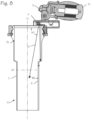
- Figure 8 illustrates a lighted cannula system with a cannula tube of non-uniform diameter, with a proximal light source consisting of two LED's 5.
- Figure 8 illustrates that the cannula tube of Figure 5 can be combined with the two-LED light source of Figures 1 through 4 , to obtain the benefits of the larger proximal lumen in a system using a light source consisting of two LED's.
- the two LED's (or two pairs) can be aimed directly distally, with the beam axes parallel to the side wall of the cannula tube, as with Figure 7 , or the beam axes may be angled toward the center of the lumen, as with Figure 2 .
- the extreme smoothness of the luminal surface provides for abundant reflection of light from the proximal light sources into the cannula distal end and minimization of shadows cast by tools disposed within the cannula lumen, without the need to resort to more complex tube constructions such as optical fibers embedded in the cannula wall, or optical transmission of light from a light ring into a transparent wall, or construction of the cannula wall to serve as a light guide with rough surface features needed to extract and deliver light at that proximal end of the cannula tube.
- the cannula tube can comprise a transparent material, it is more conveniently made of metal, such as stainless steel or aluminum, which can be made with thinner walls vis-à-vis plastics, and can be sterilized and re-used, and is not subject to abrasion or skiving from abrading tools (more of a concern for spinal surgery).
- the cannula tube can consist of an opaque material, preferably metal, without embedded optical fibers or wave guide features.
- the cannula tube can also consist of a transparent polymer, without embedded optical fibers or wave guide features, though the transparency of the tube is not necessary to obtain the advantages of the inventive features of the cannula system.
- the cannula tube can be made of other materials, with a highly reflective material adhered to the luminal walls, which will also provide for good light transmission from the proximal lighting assembly, without embedded optical fibers or wave guide features.
- the luminal surface of the cannula tube may be coated to enhance performance in various aspects.
- the luminal surface may be coated with parylene or other dielectric compound for use in surgeries that require delivery of ablation energy through tools to be inserted into a surgical workspace through the cannula tube.
- the luminal surface may be coated with a hydrophobic coating, or a lipophobic or oleophobic coating, to minimize build-up of body fluids or irrigation fluids during use.
Landscapes
- Health & Medical Sciences (AREA)
- Life Sciences & Earth Sciences (AREA)
- Surgery (AREA)
- Animal Behavior & Ethology (AREA)
- Veterinary Medicine (AREA)
- Public Health (AREA)
- General Health & Medical Sciences (AREA)
- Engineering & Computer Science (AREA)
- Biomedical Technology (AREA)
- Medical Informatics (AREA)
- Heart & Thoracic Surgery (AREA)
- Nuclear Medicine, Radiotherapy & Molecular Imaging (AREA)
- Molecular Biology (AREA)
- Pathology (AREA)
- Optics & Photonics (AREA)
- Physics & Mathematics (AREA)
- Biophysics (AREA)
- Radiology & Medical Imaging (AREA)
- Oral & Maxillofacial Surgery (AREA)
- Chemical & Material Sciences (AREA)
- Inorganic Chemistry (AREA)
- Epidemiology (AREA)
- Microelectronics & Electronic Packaging (AREA)
- Endoscopes (AREA)
Description
- The inventions described below relate to the field of cannula systems for minimally invasive brain or spine surgery.
-
U.S. Patent 10,172,525 US 2007/0100210 discloses a lighted cannula that uses a light source in the form of a large light box remote from the cannula and connected via a lengthy fiber optic cable to a light-distributing ring on the proximal end of a cannula. The ring is configured to provide even, circumferential light about the interior of the cannula.US2007/276191 also uses a light source in the form of a large light box remote from the cannula and connected via a lengthy fiber optic cable to numerous optical fibers that run through the wall of the cannula to emit light at the distal end of the cannula.WO 2015/101624 discloses a lighted cannula in the form of a light guide, in which the wall of the cannula must be transparent, and the surfaces must have a specular finish to promote total internal reflectance necessary for the cannula to function as a light guide.WO 2015/101624 also uses a light source in the form of a light box, remote from the cannula and connected via a lengthy fiber optic cable to a light distributing ring about the proximal end of the cannula. - The invention is defined by independent claim 1. Further embodiments are defined in the dependent claims. The devices and methods described below provide for improved lighting and/or reduced lighting requirements for cannulas used for minimally invasive surgery. A cannula suitable for use in minimally invasive surgery is improved with a highly polished and very smooth luminal wall and/or LED's or other light sources focused at particular angles relative to the axis of the cannula.
-
-
Figures 1 through 4 illustrate a lighted cannula system. -
Figures 5 through 7 illustrate a lighted cannula system with an cannula tube of non-uniform diameter. -
Figure 8 illustrates a lighted cannula system with a cannula tube of non-uniform diameter, with a proximal light source consisting of two LED's. -
Figure 1 illustrates a cannula system 1 for accessing a target site in the body of a patient. The cannula system comprises acannula tube 2 and alighting assembly 3 disposed proximate theproximal end 2p of the cannula tube. Thelighting assembly 3 comprises ahousing 4 with a number of lights 5 (LED's, incandescent bulbs, etc.). The lighting assembly may be mounted on a ring, orpartial ring 6 as illustrated, and may be permanently fixed or releasably attachable to theproximal end 2p of the cannula tube, through releasable attachment means such as a C-ring expandable to engage a groove in the proximal end outer surface, or with an annular snap ring, or with screw threads or other easily attachable and detachable mechanisms. The lighting assembly may instead be directly fixed to the proximal end of the cannula tube or fixed on thering 18 which in turn is fixed to the cannula tube (as shown inFigure 5 through 8 ). The cannula tube is characterized by adistal end 2d and aproximal end 2p, and alumen 7 extending from the proximal end to the distal end, a centrallongitudinal axis 2L defined by the lumen, and a luminal surface 8 on the inner wall of the cannula tube. The cannula tube most conveniently has a circular radial cross section, but the radial cross section may be varied to provide for access to particular surgical sites. The cannula tube may consist of an opaque material, non-transmissive to visible light, such as metal, or it may comprise an opaque construction including a luminal surface comprising an opaque material which is non-transmissive to visible light in a cannula tube of transmissive or non-transmissive material (for example, an acrylic tube with a metallic coating). - The
lighting assembly 3 is disposed proximate the proximal end of the cannula tube, and is configured to holdlight 5 proximal to the proximal opening of the cannula tube (this is preferable, but the lights may extend slightly distally into the lumen) to project light into the lumen of the cannula tube. The cannula tube may consist of an opaque material, non-transmissive to visible light, and is preferably made of metal such as stainless steel or aluminum. - The effectiveness of the lighting is preferably enhanced by providing a very smooth surface on the inner wall of the cannula tube. Preferably, the luminal surface is highly polished/smooth with an Average Roughness of 8 microinches or smoother (8-6 inches, equivalent to Ra (um) 0.2 (0.2 microns), USA #8 finish, Japan Buff #300, or ISO N4 or smoother), to enhance the transmission of light from the proximal end of the cannula to the distal end of the cannula and a target site beyond the distal end of the cannula. The lights of
Figure 1 may have a total output of 200 to 700 lumens, which, in combination with the smooth luminal surface, will provide in ample light at a surgical workspace at the distal end of the cannula tube. Combinations of slightly rougher surfaces with higher power lights may be used. The luminal surface may be provided in a Average Roughness in the range of 9 to 32 micro-inches (between 0.22 to 0.81 micrometers, ISO N5 or N6 finish, #6 or #7 finish (roughly), Japan Buff #100 or smoother) and the lights may be chosen to provide additional lumens, in the higher end of the range. Alternatively, the luminal surface may be provided in a Average Roughness in the range of 33 to 63 micro-inches (0.82 to 1.6 micrometers, ISO N7 finish, USA #3 or #4 finish) and the lights may be chosen to provide additional lumens, in the higher end of the range. - As illustrated in
Figure 2 , thelight 5 are characterized by a main beam axis 9, which may be directed at an angle α1 of 70° to 85°, though preferably about 80° downward (distally) from theradial axis 2R, or, comparably, directed at an angle β1 or 5° to 15° , and preferably about 10°, inward relative to thelong axis 2L of the cannula tube, directed distally, in this embodiment where the cannula has a distal portion with a straight inner bore (of consistent diameter throughout the length of the distal portion) and a proximal conical section with a conical bore which is larger than the diameter of the straight inner bore at the proximal end of the proximal conical section and necks down to match the diameter of the straight inner bore of the straight distal portion. - As illustrated in
Figure 2 , the lights are characterized by a main beam axis 9, which may be directed at an angle α1 of 80° from theradial axis 2R, directed distally, or at an angle β1 of 10° relative to the luminal surface of the cannula tube (toward the center of the lumen). - Though
Figures 1 and2 illustrate the system with a cannula tube having a conical lumen in a proximal portion of the cannula tube, the cannula tube may be isodiametric throughout its length, having a consistent or uniform inner diameter and straight luminal walls from the proximal end to the distal end, without a conical portion or a neckdown portion. -
Figure 3 is a view of the cannula system from the bottom, or distal end of the cannula tube. As shown in this Figure, the beam axis 9 may be aimed to intersect the central axis 2C of the cannula tube, or the beam axis may be aimed at angle γ from theradian 2R (the line between the LED and the central axis 2C, or, along a chord of the circle defined by the cannula tube). This angle is preferably in the range of about 10 to 30°. As shown inFigures 3 and4 , the light source may consist of only two LED's disposed over (proximal to) the proximal end of the cannula tube, either directly or on thering 6 and separated by a first arc α2 of 50° to 70°, and preferably about 60° as shown inFigure 3 (or, conversely, the second arc β2 of 290° to 310°, and preferably about 300° as shown inFigure 3 ). The light source may consist of two pairs of closely spaced lights, with the pairs similarly separated. Preferably, the lights and any associated lenses are disposed proximal to the proximal opening of the cannula tube without extending distally into the lumen. The proximal end of the cannula tube has an inner bore/lumen that is conical, with a proximal opening slightly larger than the diameter of the distal portion of the cannular tube. - As shown in
Figure 1 , the cannula system may include acamera assembly 10 secured to the proximal end of the cannula, with a portion of the camera assembly overhanging the lumen and extending into a cylindrical space defined by the lumen of the cannula tube. The camera assembly has a distalmost optical surface, which may be a distal surface of an objective lens or a prism (theprism 11 is shown inFigure 2 , and the distal-mostoptical surface 12 is visible in the distal view ofFigure 3 ), and the distal-most optical surface is disposed proximate the proximal end of the cannula tube. The objective lens or prism may be the portion of the camera assembly overhanging the lumen. The distal-most optical surface of the camera system is spaced proximally from the proximal end of the cannula tube in the illustration, but may be placed a short distance distal to the very proximal edge of the cannula tube (without extending to the distal end of the cannula tube). Also as shown inFigure 1 , the cannula system can include atab 13 for securing the cannula to a table-fixed flex arm. As illustrated inFigures 3 and4 , the distal most optical surface of the camera assembly is disposed between the lights, in the smaller arc α2 separating the two lights. A gap in the housing, between the two lights (or two pairs of lights), provides an unobstructed sight-line between the distal-most optical surface and the workspace at the distal end of the cannula tube, and the distal most optical surface of the camera assembly is disposed within this gap or proximal to the gap. -
Figure 5 illustrates a second version of the cannula system for accessing a target site in the body of a patient. The cannula system 14 ofFigure 5 comprises acannula tube 15 and alighting assembly 16 disposed proximate the proximal end of the cannula tube. Thelighting assembly 16 comprises a number of lights 17 (LED's, incandescent bulbs, etc.) mounted on aring 18 as illustrated (though a partial ring may be used, or the ring may be omitted), and may be permanently fixed or releasably attachable to the proximal end of the cannula tube, through releasable attachment means such as an annular snap ring, a threaded fitting (or a C-ring expandable to engage a groove in the proximal end outer surface). The cannula tube is characterized by adistal end 15d and aproximal end 15p, and alumen 19 extending from the proximal end to the distal end, a centrallongitudinal axis 15L defined by the lumen, and aluminal surface 20 on an inner wall of the cannula tube. The inner diameter of the cannula tubeproximal end 15p is longitudinally isodiametric (straight-walled, and not conical as inFigure 2 ), and the inner diameter of the cannula tubedistal end 15d is longitudinally isodiametric, and the inner diameter of the cannula tube distal end is smaller than the inner diameter of that cannula tube proximal end, and the cannula tubeproximal end 15p and cannula tubedistal end 15d are joined by a neck-downportion 15N of the cannula tube. - Similar to the construction described in relation to
Figures 1 through 3 , thelighting assembly 16 ofFigure 5 is disposed proximate the proximal end of the cannula tube, and is configured to project light into the lumen of the cannula tube. The cannula tube may consist of an opaque material, non-transmissive to visible light, again preferably metal such as stainless steel or aluminum. The luminal surface is highly polished/smooth with a Average Roughness less that 8 micro-inches (1 micro-inch ≈ 0.0254 microns), to enhance the transmission of light from the proximal end of the cannula to the distal end of the cannula and a target site beyond the distal end of the cannula. The lights ofFigure 5 may have a total output of 1500 to 2500 lumens, which, in combination with the smooth luminal surface, will provide in ample light at a surgical workspace at the distal end of the cannula tube. As with the cannula tube ofFigure 1 , the lights may be chosen to provide additional lumens, in the higher end of the range, with luminal walls of Average Roughness within the range of 9 to 32 micro-inches or in the range of 33 to 63 micro-inches. - As shown in
Figure 6 , thelighting assembly 16 may comprise a plurality of LED's 17 disposed on the proximal end of the cannula tube, either directly fixed to the proximal end of the cannula tube or fixed on thering 18 which in turn is fixed to the cannula tube. Thering 18 may be permanently fixed or releasably attachable to theproximal end 15p of the cannula tube, through releasable attachment means such as a C-ring expandable to engage a groove in the proximal end outer surface, or with an annular snap ring, or with screw threads or other easily attachable and detachable mechanisms. - As shown in the cross section of
Figure 7 , thelights 17 are characterized by amain beam axis 21, which may be directed parallel to the straight side wall or the portion of the luminal surface on the inner wall of the proximal end of the cannula tube (that is, the beam axes of each LED may be parallel to a portion of the luminal surface on an inner wall of the cannula). Alternatively, as in the systems ofFigures 1 and2 , themain beam axis 21 may also be directed at an angle α1 of 70° to 85°, though preferably about 80° downward (distally) from theradial axis 2R, or, comparably, directed at an angle β1 of 5° to 15°, and preferably about 10° relative to the luminal surface of the cannula tube (toward the center of the lumen). - The cannula system of
Figure 5 may include acamera assembly 10 secured to the proximal end of the cannula, with a portion of the camera assembly overhanging the lumen and extending into a cylindrical space defined by the lumen of the cannula tube. The camera assembly has a distal-most optical surface, which may be a distal surface of an objective lens or a prism, and the distal-most optical surface is disposed proximate the proximal end of the cannula tube, the objective lens or prism may be the portion of the camera assembly overhanging the lumen. The distal-most optical surface of the camera system is spaced proximally from the proximal end of the cannula tube in the illustration, but may be placed a short distance distal to the very proximal edge of the cannula tube. -
Figure 8 illustrates a lighted cannula system with a cannula tube of non-uniform diameter, with a proximal light source consisting of two LED's 5.Figure 8 illustrates that the cannula tube ofFigure 5 can be combined with the two-LED light source ofFigures 1 through 4 , to obtain the benefits of the larger proximal lumen in a system using a light source consisting of two LED's. In this embodiment, the two LED's (or two pairs) can be aimed directly distally, with the beam axes parallel to the side wall of the cannula tube, as withFigure 7 , or the beam axes may be angled toward the center of the lumen, as withFigure 2 . - The extreme smoothness of the luminal surface provides for abundant reflection of light from the proximal light sources into the cannula distal end and minimization of shadows cast by tools disposed within the cannula lumen, without the need to resort to more complex tube constructions such as optical fibers embedded in the cannula wall, or optical transmission of light from a light ring into a transparent wall, or construction of the cannula wall to serve as a light guide with rough surface features needed to extract and deliver light at that proximal end of the cannula tube. Though the cannula tube can comprise a transparent material, it is more conveniently made of metal, such as stainless steel or aluminum, which can be made with thinner walls vis-à-vis plastics, and can be sterilized and re-used, and is not subject to abrasion or skiving from abrading tools (more of a concern for spinal surgery). Thus, the cannula tube can consist of an opaque material, preferably metal, without embedded optical fibers or wave guide features. The cannula tube can also consist of a transparent polymer, without embedded optical fibers or wave guide features, though the transparency of the tube is not necessary to obtain the advantages of the inventive features of the cannula system.
- Alternatively, the cannula tube can be made of other materials, with a highly reflective material adhered to the luminal walls, which will also provide for good light transmission from the proximal lighting assembly, without embedded optical fibers or wave guide features.
- The luminal surface of the cannula tube may be coated to enhance performance in various aspects. The luminal surface may be coated with parylene or other dielectric compound for use in surgeries that require delivery of ablation energy through tools to be inserted into a surgical workspace through the cannula tube. The luminal surface may be coated with a hydrophobic coating, or a lipophobic or oleophobic coating, to minimize build-up of body fluids or irrigation fluids during use.
- While the preferred embodiments of the devices and methods have been described in reference to the environment in which they were developed, they are merely illustrative of the principles of the inventions. The elements of the various embodiments may be incorporated into each of the other species to obtain the benefits of those elements in combination with such other species, and the various beneficial features may be employed in embodiments alone or in combination with each other.
Claims (18)
- A cannula system (1, 14) for accessing a target site in the body of a patient, said cannula system comprising:a cannula tube (2, 15) having a distal end (2d, 15d) and a proximal end (2p, 15p), and a lumen (7, 19) extending from said proximal end (2p, 15p) to said distal end (2d, 15d), a central longitudinal axis (2L, 15L) defined by the lumen (7, 19), and a luminal surface (8, 20) on an inner wall of said cannula tube (2, 15); anda light source disposed proximate the proximal end (2p, 15p) of the cannula tube (2, 15), said light source configured to project light into the lumen (7, 19) of the cannula tube (2, 15); whereinthe cannula tube comprises an opaque material, non-transmissive to visible light;characterized in that the luminal surface (8, 20) has an Average Roughness of about 0.2 microns (8 micro-inches) or smoother.
- The cannula system (1, 14) of claim 1, wherein:
the cannula tube (2, 15) consists entirely of a material which is non-transmissive to visible light. - The cannula system (1, 14) of claim 1, wherein:
the cannula tube (2, 15) comprises a material which is transmissive to visible light with a luminal surface (8, 20) comprising a material which is non-transmissive to visible light. - The cannula system (1, 14) of claim 1, wherein:
the light source comprises a plurality of lights (5, 17) disposed on the proximal end (2p, 15p) of the cannula tube (2, 15), where the lights (5, 17) are characterized by a main beam axis (9, 21), and said main beam axis (9, 21) is directed at an angle of about 80° from a radial axis (2R) of the cannula tube (2, 15). - The cannula system (1, 14) of claim 1, wherein:
the light source comprises of a plurality of lights (5, 17) disposed on the proximal end (2p, 15p) of the cannula tube (2, 15), where the lights are characterized by a main beam axis (9, 21), and said main beam axis (9, 21) is directed at an angle of about 10° relative to the luminal surface (8, 20) of the cannula tube (2, 15). - The cannula system (1, 14) of claim 1, wherein:
the light source comprises of a plurality of lights (5, 17) disposed on the proximal end (2p, 15p) of the cannula tube (2, 15), where the lights (5, 17) are characterized by a main beam axis (9, 21), and said main beam axis (9, 21) is directed parallel to a portion of the luminal surface (8, 20) on an inner wall of the cannula. - The cannula system (1, 14) of claim 1, wherein:
the light source is characterized by a main beam axis (9, 21),
and said beam axis (9, 21) is aimed at angle of 10 to 30° from a radian of the cannula tube. - The cannula system (1, 14) of any of claims 2 through 7, wherein:
the light source consists of two lights (5, 17), disposed on the proximal end (2p, 15p) of the cannula tube (2, 15) and separated by a first arc of about 60°, or two pairs of closely spaced lights (5, 17), with the pairs separated by a first arc of about 60°. - The cannula system (1, 14) of any of claims 2 through 7, wherein:
the inner diameter of that cannula tube proximal end (2p, 15p) is conical, and the inner diameter of the cannula tube distal end (2d, 15d) is isodiametric. - The cannula system (1, 14) of any of claims 2 through 7, wherein:
the inner diameter of the cannula tube proximal end (2p, 15p) is isodiametric, and the inner diameter of the cannula tube distal end (2d, 15d) is isodiametric, and the inner diameter of the cannula tube distal end (2d, 15d) is smaller than the inner diameter of the cannula tube proximal end (2p, 15p), and the cannula tube proximal end (2p, 15p) and cannula tube distal end (2d, 15d) are joined by a neck-down portion of the cannula tube (2, 15). - The cannula system (1, 14) of any of claims 2 through 7, wherein:
the inner diameter of the cannula tube (2, 15), from the proximal end (2p, 15p) to the distal end (2p, 15p), is isodiametric. - The cannula system (1, 14) of any of claims 2 through 7, wherein: the cannula tube (2, 15) consists of metal.
- The cannula system (1, 14) of any of claims 2 through 7, wherein:
the opaque material of the cannula tube (2, 15) is free of any optical fibers. - The cannula system (1, 14) of any of claims 2 through 7, further comprising:a camera assembly (10) secured to the proximal end (2p, 15p) of the cannula, with a portion of the camera assembly (10) overhanging the lumen (7, 19) and extending into a cylindrical space defined by the lumen (7, 19) of the cannula tube (2, 15); whereinthe camera assembly (10) has a distal-most optical surface (12), and said distal-most optical surface (12) is disposed proximate the proximal end (2p, 15p) of the cannula tube (2, 15).
- The cannula system (1, 14) of claim 8, further comprising:a camera assembly (10) secured to the proximal end (2p, 15p) of the cannula, with a portion of the camera assembly (19) overhanging the lumen (7, 19) and extending into a cylindrical space defined by the lumen (7, 19) of the cannula tube (2, 15); whereinthe camera assembly (10) has a distal-most optical surface (12), and said distal-most optical surface (12) is disposed proximate the proximal end (2p, 15p) of the cannula tube (2, 15); whereinthe camera assembly (10) is radially disposed between the two lights, within the first arc of about 60°.
- The cannula system (1, 14) of any of claims 2 through 7, further comprising:
an electrically isolating coating on the luminal surface of the cannula tube (2, 15). - The cannula system (1, 14) of any of claims 2 through 7, further comprising:
a hydrophobic coating on the luminal surface of the cannula tube (2, 15). - The cannula system (1, 14) of any of claims 2 through 7, further comprising:
a lipophobic or oleophobic coating on the luminal surface of the cannula tube (2, 15).
Applications Claiming Priority (2)
| Application Number | Priority Date | Filing Date | Title |
|---|---|---|---|
| US201962803276P | 2019-02-08 | 2019-02-08 | |
| PCT/US2020/017276 WO2020163753A1 (en) | 2019-02-08 | 2020-02-07 | Lighted cannula system |
Publications (3)
| Publication Number | Publication Date |
|---|---|
| EP3920815A1 EP3920815A1 (en) | 2021-12-15 |
| EP3920815A4 EP3920815A4 (en) | 2022-09-21 |
| EP3920815B1 true EP3920815B1 (en) | 2024-06-12 |
Family
ID=71946513
Family Applications (1)
| Application Number | Title | Priority Date | Filing Date |
|---|---|---|---|
| EP20752885.2A Active EP3920815B1 (en) | 2019-02-08 | 2020-02-07 | Lighted cannula system |
Country Status (8)
| Country | Link |
|---|---|
| US (1) | US12016534B2 (en) |
| EP (1) | EP3920815B1 (en) |
| JP (1) | JP7633934B2 (en) |
| KR (1) | KR102911029B1 (en) |
| CN (1) | CN113423349A (en) |
| AU (1) | AU2020219357B2 (en) |
| CA (1) | CA3127963A1 (en) |
| WO (1) | WO2020163753A1 (en) |
Families Citing this family (6)
| Publication number | Priority date | Publication date | Assignee | Title |
|---|---|---|---|---|
| US12016534B2 (en) * | 2019-02-08 | 2024-06-25 | Rebound Therapeutics Corporation | Lighted cannula system |
| KR20230096076A (en) * | 2020-10-29 | 2023-06-29 | 어플라이드 메디컬 리소시스 코포레이션 | Material Combinations and Processing Methods for Surgical Instruments |
| JP2023010634A (en) | 2021-07-07 | 2023-01-20 | ニコ コーポレイション | flexible instrument delivery device |
| US11723641B2 (en) | 2021-08-03 | 2023-08-15 | Viseon, Inc. | Camera system for use with retractors |
| JP7777966B2 (en) * | 2021-11-30 | 2025-12-01 | Tdk株式会社 | Multilayer coil components |
| US12616356B2 (en) * | 2023-08-30 | 2026-05-05 | Karl Storz Imaging, Inc. | Endoscopic illumination sleeve |
Family Cites Families (65)
| Publication number | Priority date | Publication date | Assignee | Title |
|---|---|---|---|---|
| US3146775A (en) * | 1962-10-29 | 1964-09-01 | Welch Allyn Inc | Illuminating means for medical instruments |
| US5325458A (en) * | 1992-02-07 | 1994-06-28 | Surgilase, Inc. | Monolithic hollow waveguide and method and apparatus for making the same |
| GB2288469B (en) * | 1994-04-15 | 1997-10-22 | Hitachi Cable | Optical hollow waveguide, method for fabricating the same, and laser transmission apparatus using the same |
| US5953477A (en) * | 1995-11-20 | 1999-09-14 | Visionex, Inc. | Method and apparatus for improved fiber optic light management |
| US6141476A (en) * | 1998-01-05 | 2000-10-31 | Matsuura; Yuji | Hollow waveguide for ultraviolet light and making the same |
| US6432101B1 (en) * | 1998-05-28 | 2002-08-13 | Pearl Technology Holdings, Llc | Surgical device for performing face-lifting using electromagnetic radiation |
| EP1087782A4 (en) * | 1998-06-15 | 2001-09-12 | Neuronz Ltd | REGULATION OF TYROSINE HYDROXYLASE |
| US6487440B2 (en) * | 1998-07-08 | 2002-11-26 | Lifespex, Inc. | Optical probe having and methods for difuse and uniform light irradiation |
| JP2004055819A (en) * | 2002-07-19 | 2004-02-19 | Univ Osaka | Laser beam concentrator and laser beam condensing method |
| WO2004012617A2 (en) * | 2002-08-02 | 2004-02-12 | Sdgi Holdings, Inc. | Systems and techniques for illuminating a surgical space |
| US7223233B2 (en) * | 2002-08-02 | 2007-05-29 | Warsaw Orthopedic, Inc. | Systems and techniques for illuminating a surgical space |
| US7354399B2 (en) * | 2003-07-28 | 2008-04-08 | Welch Allyn, Inc. | Otoscopic tip element and related method of use |
| US7488322B2 (en) * | 2004-02-11 | 2009-02-10 | Medtronic, Inc. | High speed surgical cutting instrument |
| US7976462B2 (en) * | 2004-04-06 | 2011-07-12 | Integrated Endoscopy, Inc. | Endoscope designs and methods of manufacture |
| US9005218B2 (en) * | 2004-04-08 | 2015-04-14 | Hsc Development Llc | Follicular extraction method and device |
| US8512229B2 (en) | 2004-04-14 | 2013-08-20 | Usgi Medical Inc. | Method and apparatus for obtaining endoluminal access |
| US8480566B2 (en) * | 2004-09-24 | 2013-07-09 | Vivid Medical, Inc. | Solid state illumination for endoscopy |
| EP1807009B1 (en) * | 2004-10-05 | 2014-11-26 | Genzyme Corporation | Stepped cannula |
| US9186175B2 (en) * | 2004-10-28 | 2015-11-17 | Nico Corporation | Surgical access assembly and method of using same |
| US9161820B2 (en) * | 2004-10-28 | 2015-10-20 | Nico Corporation | Surgical access assembly and method of using same |
| US20060224045A1 (en) * | 2005-03-31 | 2006-10-05 | Depuy Spine, Inc. | Integrated access device and light source for surgical procedures |
| US9005115B2 (en) * | 2005-04-04 | 2015-04-14 | Invuity, Inc. | Illuminated telescoping cannula |
| US7510524B2 (en) * | 2005-04-04 | 2009-03-31 | Invuity, Inc. | Optical waveguide sheath |
| JP5196711B2 (en) * | 2005-07-26 | 2013-05-15 | 京セラ株式会社 | LIGHT EMITTING DEVICE AND LIGHTING DEVICE USING THE SAME |
| US20070100210A1 (en) * | 2005-11-02 | 2007-05-03 | Depuy Spine, Inc. | Illuminated surgical access system including a surgical access device and coupled light emitter |
| US7874982B2 (en) * | 2005-11-02 | 2011-01-25 | Depuy Spine, Inc. | Illuminated surgical access system including a surgical access device and coupled light emitter |
| ATE484264T1 (en) * | 2005-12-16 | 2010-10-15 | Alcon Inc | ILLUMINATED INFUSION CANNULA |
| US8409088B2 (en) * | 2006-01-18 | 2013-04-02 | Invuity, Inc. | Retractor illumination system |
| US8430813B2 (en) | 2006-05-26 | 2013-04-30 | Depuy Spine, Inc. | Illuminated surgical access system including a surgical access device and integrated light emitter |
| US20090163897A1 (en) * | 2007-12-19 | 2009-06-25 | Skinner Allen W | Illuminated Ophthalmic Instruments |
| US9282878B2 (en) * | 2008-08-13 | 2016-03-15 | Invuity, Inc. | Cyclo olefin polymer and copolymer medical devices |
| US8795162B2 (en) * | 2009-11-10 | 2014-08-05 | Invuity, Inc. | Illuminated suction apparatus |
| US8292805B2 (en) * | 2009-11-10 | 2012-10-23 | Invuity, Inc. | Illuminated suction apparatus |
| US8568304B2 (en) * | 2010-12-16 | 2013-10-29 | Invuity, Inc. | Illuminated suction apparatus |
| US9289114B2 (en) * | 2010-07-30 | 2016-03-22 | Nilesh R. Vasan | Disposable, self-contained laryngoscope and method of using same |
| JP5190104B2 (en) * | 2010-12-07 | 2013-04-24 | クリエートメディック株式会社 | Trocar |
| WO2013044151A1 (en) * | 2011-09-23 | 2013-03-28 | Invuity, Inc. | Illuminated and modular soft tissue retractor |
| AU2012352056B2 (en) * | 2011-12-14 | 2015-10-01 | Arrow International, Inc. | Surface modification for catheters comprised of multiple materials |
| EP2790745B1 (en) * | 2011-12-14 | 2017-09-27 | Arrow International, Inc. | Luminal modifications for catheters |
| EP2790744A4 (en) * | 2011-12-14 | 2015-06-24 | Semprus Biosciences Corp | Surface modification for dialysis catheters |
| US9295808B2 (en) * | 2012-08-14 | 2016-03-29 | Cardiac Pacemakers, Inc. | Medical device with textured surface |
| WO2014029424A1 (en) * | 2012-08-21 | 2014-02-27 | Optomeditech Oy | Solid introducer needle for catheter |
| US20150025369A1 (en) * | 2013-07-17 | 2015-01-22 | Corning Incorporated | Housing for the oct probe, oct probe assembly, and a method of making such assembly |
| US10342563B2 (en) * | 2013-07-19 | 2019-07-09 | DePuy Synthes Products, Inc. | Anti-clogging device for a vacuum-assisted, tissue removal system |
| US20150045624A1 (en) * | 2013-08-06 | 2015-02-12 | Minimally Invasive Surgical Access Limited | Intra-Thoracic Access Device Without Thoracotomy, and Related Methods |
| US9694114B2 (en) * | 2013-08-07 | 2017-07-04 | Arrow International, Inc. | Antimicrobial catheters with permeabilization agents |
| EP3046458B1 (en) * | 2013-09-20 | 2020-10-21 | Camplex, Inc. | Surgical visualization systems |
| US9408631B2 (en) * | 2013-09-27 | 2016-08-09 | Depuy Mitek, Llc | Flexible cannula and obturator |
| ES2539523B1 (en) * | 2013-12-31 | 2016-01-13 | Fundación Tekniker | Vitreoctomy device |
| US9357906B2 (en) * | 2014-04-16 | 2016-06-07 | Engineered Medical Solutions Company LLC | Surgical illumination devices and methods therefor |
| EP3685734B1 (en) * | 2014-05-22 | 2022-03-09 | Invuity, Inc. | Medical device featuring cladded waveguide |
| WO2016010998A2 (en) * | 2014-07-15 | 2016-01-21 | Texas Tech University System | Self-deployed cuff and skirt tracheal tube |
| GB2548314B (en) * | 2014-12-23 | 2020-06-17 | Synaptive Medical Barbados Inc | System for illumination during a corridor based procedure |
| WO2016164067A1 (en) * | 2015-04-07 | 2016-10-13 | MRISafetyModeling, LLC | Conductive multi-layer polymer catheter for active implantable medical device leads and extensions |
| US10363056B2 (en) * | 2015-06-17 | 2019-07-30 | Saphena Medical, Inc. | Unitary endoscopic vessel harvesting devices |
| US10376281B2 (en) * | 2016-08-17 | 2019-08-13 | Rebound Therapeutics Corporation | Cannula with proximally mounted camera |
| US10172525B2 (en) * | 2015-08-17 | 2019-01-08 | Rebound Therapeutics Corporation | Cannula with proximally mounted camera |
| US11173008B2 (en) * | 2015-11-01 | 2021-11-16 | Alcon Inc. | Illuminated ophthalmic cannula |
| EP3181988A1 (en) * | 2015-12-16 | 2017-06-21 | Ivoclar Vivadent AG | Homogenizer |
| US9956053B2 (en) * | 2016-03-04 | 2018-05-01 | Novartis Ag | Cannula with an integrated illumination feature |
| JP2017221658A (en) * | 2016-06-10 | 2017-12-21 | 株式会社Jvcケンウッド | Rigid endoscope system |
| US10105042B2 (en) * | 2016-08-17 | 2018-10-23 | Rebound Therapeutics Corporation | Cannula with proximally mounted camera |
| US20190307527A1 (en) * | 2018-04-09 | 2019-10-10 | Alcon Inc. | Fiber Tip Protection Integration For Cannula |
| US12016534B2 (en) * | 2019-02-08 | 2024-06-25 | Rebound Therapeutics Corporation | Lighted cannula system |
| US12502058B2 (en) * | 2021-02-18 | 2025-12-23 | Covidien Lp | Laryngoscope blade with glare-reducing features |
-
2020
- 2020-02-07 US US16/785,187 patent/US12016534B2/en active Active
- 2020-02-07 KR KR1020217028119A patent/KR102911029B1/en active Active
- 2020-02-07 CN CN202080012514.2A patent/CN113423349A/en active Pending
- 2020-02-07 CA CA3127963A patent/CA3127963A1/en active Pending
- 2020-02-07 WO PCT/US2020/017276 patent/WO2020163753A1/en not_active Ceased
- 2020-02-07 JP JP2021544202A patent/JP7633934B2/en active Active
- 2020-02-07 AU AU2020219357A patent/AU2020219357B2/en active Active
- 2020-02-07 EP EP20752885.2A patent/EP3920815B1/en active Active
Also Published As
| Publication number | Publication date |
|---|---|
| US12016534B2 (en) | 2024-06-25 |
| JP2022519213A (en) | 2022-03-22 |
| AU2020219357B2 (en) | 2025-03-20 |
| WO2020163753A1 (en) | 2020-08-13 |
| US20200253464A1 (en) | 2020-08-13 |
| KR20210114068A (en) | 2021-09-17 |
| EP3920815A4 (en) | 2022-09-21 |
| KR102911029B1 (en) | 2026-01-09 |
| EP3920815A1 (en) | 2021-12-15 |
| CA3127963A1 (en) | 2020-08-13 |
| CN113423349A (en) | 2021-09-21 |
| AU2020219357A1 (en) | 2021-08-12 |
| JP7633934B2 (en) | 2025-02-20 |
Similar Documents
| Publication | Publication Date | Title |
|---|---|---|
| US12016534B2 (en) | Lighted cannula system | |
| EP1959886B1 (en) | Illuminated infusion cannula | |
| US7731710B2 (en) | Surgical wide-angle illuminator | |
| US10810496B2 (en) | Medical device featuring cladded waveguide | |
| CN101188966B (en) | Optical waveguide sheath | |
| EP2486855B1 (en) | Retractor illumination system | |
| US20170100023A1 (en) | Illuminated telescoping cannula | |
| JP2022519213A5 (en) | ||
| CA3151635C (en) | Cannula with illumination |
Legal Events
| Date | Code | Title | Description |
|---|---|---|---|
| STAA | Information on the status of an ep patent application or granted ep patent |
Free format text: STATUS: THE INTERNATIONAL PUBLICATION HAS BEEN MADE |
|
| PUAI | Public reference made under article 153(3) epc to a published international application that has entered the european phase |
Free format text: ORIGINAL CODE: 0009012 |
|
| STAA | Information on the status of an ep patent application or granted ep patent |
Free format text: STATUS: REQUEST FOR EXAMINATION WAS MADE |
|
| 17P | Request for examination filed |
Effective date: 20210908 |
|
| AK | Designated contracting states |
Kind code of ref document: A1 Designated state(s): AL AT BE BG CH CY CZ DE DK EE ES FI FR GB GR HR HU IE IS IT LI LT LU LV MC MK MT NL NO PL PT RO RS SE SI SK SM TR |
|
| DAV | Request for validation of the european patent (deleted) | ||
| DAX | Request for extension of the european patent (deleted) | ||
| A4 | Supplementary search report drawn up and despatched |
Effective date: 20220823 |
|
| RIC1 | Information provided on ipc code assigned before grant |
Ipc: A61L 29/02 20060101ALI20220817BHEP Ipc: A61B 17/00 20060101ALI20220817BHEP Ipc: A61B 90/30 20160101ALI20220817BHEP Ipc: A61B 17/34 20060101AFI20220817BHEP |
|
| P01 | Opt-out of the competence of the unified patent court (upc) registered |
Effective date: 20230518 |
|
| GRAP | Despatch of communication of intention to grant a patent |
Free format text: ORIGINAL CODE: EPIDOSNIGR1 |
|
| STAA | Information on the status of an ep patent application or granted ep patent |
Free format text: STATUS: GRANT OF PATENT IS INTENDED |
|
| RIC1 | Information provided on ipc code assigned before grant |
Ipc: A61B 17/20 20060101ALI20240202BHEP Ipc: A61B 1/313 20060101ALI20240202BHEP Ipc: A61B 1/06 20060101ALI20240202BHEP Ipc: A61B 90/30 20160101ALI20240202BHEP Ipc: A61B 17/00 20060101ALI20240202BHEP Ipc: A61L 29/02 20060101ALI20240202BHEP Ipc: A61B 1/04 20060101ALI20240202BHEP Ipc: A61B 17/34 20060101AFI20240202BHEP |
|
| INTG | Intention to grant announced |
Effective date: 20240229 |
|
| GRAS | Grant fee paid |
Free format text: ORIGINAL CODE: EPIDOSNIGR3 |
|
| GRAA | (expected) grant |
Free format text: ORIGINAL CODE: 0009210 |
|
| STAA | Information on the status of an ep patent application or granted ep patent |
Free format text: STATUS: THE PATENT HAS BEEN GRANTED |
|
| AK | Designated contracting states |
Kind code of ref document: B1 Designated state(s): AL AT BE BG CH CY CZ DE DK EE ES FI FR GB GR HR HU IE IS IT LI LT LU LV MC MK MT NL NO PL PT RO RS SE SI SK SM TR |
|
| REG | Reference to a national code |
Ref country code: GB Ref legal event code: FG4D |
|
| REG | Reference to a national code |
Ref country code: CH Ref legal event code: EP |
|
| REG | Reference to a national code |
Ref country code: IE Ref legal event code: FG4D |
|
| REG | Reference to a national code |
Ref country code: DE Ref legal event code: R096 Ref document number: 602020032332 Country of ref document: DE |
|
| PG25 | Lapsed in a contracting state [announced via postgrant information from national office to epo] |
Ref country code: BG Free format text: LAPSE BECAUSE OF FAILURE TO SUBMIT A TRANSLATION OF THE DESCRIPTION OR TO PAY THE FEE WITHIN THE PRESCRIBED TIME-LIMIT Effective date: 20240612 |
|
| PG25 | Lapsed in a contracting state [announced via postgrant information from national office to epo] |
Ref country code: FI Free format text: LAPSE BECAUSE OF FAILURE TO SUBMIT A TRANSLATION OF THE DESCRIPTION OR TO PAY THE FEE WITHIN THE PRESCRIBED TIME-LIMIT Effective date: 20240612 Ref country code: HR Free format text: LAPSE BECAUSE OF FAILURE TO SUBMIT A TRANSLATION OF THE DESCRIPTION OR TO PAY THE FEE WITHIN THE PRESCRIBED TIME-LIMIT Effective date: 20240612 |
|
| REG | Reference to a national code |
Ref country code: LT Ref legal event code: MG9D |
|
| PG25 | Lapsed in a contracting state [announced via postgrant information from national office to epo] |
Ref country code: GR Free format text: LAPSE BECAUSE OF FAILURE TO SUBMIT A TRANSLATION OF THE DESCRIPTION OR TO PAY THE FEE WITHIN THE PRESCRIBED TIME-LIMIT Effective date: 20240913 |
|
| REG | Reference to a national code |
Ref country code: NL Ref legal event code: MP Effective date: 20240612 |
|
| PG25 | Lapsed in a contracting state [announced via postgrant information from national office to epo] |
Ref country code: ES Free format text: LAPSE BECAUSE OF FAILURE TO SUBMIT A TRANSLATION OF THE DESCRIPTION OR TO PAY THE FEE WITHIN THE PRESCRIBED TIME-LIMIT Effective date: 20240612 |
|
| PG25 | Lapsed in a contracting state [announced via postgrant information from national office to epo] |
Ref country code: LV Free format text: LAPSE BECAUSE OF FAILURE TO SUBMIT A TRANSLATION OF THE DESCRIPTION OR TO PAY THE FEE WITHIN THE PRESCRIBED TIME-LIMIT Effective date: 20240612 |
|
| PG25 | Lapsed in a contracting state [announced via postgrant information from national office to epo] |
Ref country code: NO Free format text: LAPSE BECAUSE OF FAILURE TO SUBMIT A TRANSLATION OF THE DESCRIPTION OR TO PAY THE FEE WITHIN THE PRESCRIBED TIME-LIMIT Effective date: 20240912 Ref country code: LV Free format text: LAPSE BECAUSE OF FAILURE TO SUBMIT A TRANSLATION OF THE DESCRIPTION OR TO PAY THE FEE WITHIN THE PRESCRIBED TIME-LIMIT Effective date: 20240612 Ref country code: HR Free format text: LAPSE BECAUSE OF FAILURE TO SUBMIT A TRANSLATION OF THE DESCRIPTION OR TO PAY THE FEE WITHIN THE PRESCRIBED TIME-LIMIT Effective date: 20240612 Ref country code: GR Free format text: LAPSE BECAUSE OF FAILURE TO SUBMIT A TRANSLATION OF THE DESCRIPTION OR TO PAY THE FEE WITHIN THE PRESCRIBED TIME-LIMIT Effective date: 20240913 Ref country code: FI Free format text: LAPSE BECAUSE OF FAILURE TO SUBMIT A TRANSLATION OF THE DESCRIPTION OR TO PAY THE FEE WITHIN THE PRESCRIBED TIME-LIMIT Effective date: 20240612 Ref country code: ES Free format text: LAPSE BECAUSE OF FAILURE TO SUBMIT A TRANSLATION OF THE DESCRIPTION OR TO PAY THE FEE WITHIN THE PRESCRIBED TIME-LIMIT Effective date: 20240612 Ref country code: BG Free format text: LAPSE BECAUSE OF FAILURE TO SUBMIT A TRANSLATION OF THE DESCRIPTION OR TO PAY THE FEE WITHIN THE PRESCRIBED TIME-LIMIT Effective date: 20240612 Ref country code: RS Free format text: LAPSE BECAUSE OF FAILURE TO SUBMIT A TRANSLATION OF THE DESCRIPTION OR TO PAY THE FEE WITHIN THE PRESCRIBED TIME-LIMIT Effective date: 20240912 |
|
| PG25 | Lapsed in a contracting state [announced via postgrant information from national office to epo] |
Ref country code: NL Free format text: LAPSE BECAUSE OF FAILURE TO SUBMIT A TRANSLATION OF THE DESCRIPTION OR TO PAY THE FEE WITHIN THE PRESCRIBED TIME-LIMIT Effective date: 20240612 |
|
| REG | Reference to a national code |
Ref country code: AT Ref legal event code: MK05 Ref document number: 1693556 Country of ref document: AT Kind code of ref document: T Effective date: 20240612 |
|
| PG25 | Lapsed in a contracting state [announced via postgrant information from national office to epo] |
Ref country code: NL Free format text: LAPSE BECAUSE OF FAILURE TO SUBMIT A TRANSLATION OF THE DESCRIPTION OR TO PAY THE FEE WITHIN THE PRESCRIBED TIME-LIMIT Effective date: 20240612 |
|
| PG25 | Lapsed in a contracting state [announced via postgrant information from national office to epo] |
Ref country code: PT Free format text: LAPSE BECAUSE OF FAILURE TO SUBMIT A TRANSLATION OF THE DESCRIPTION OR TO PAY THE FEE WITHIN THE PRESCRIBED TIME-LIMIT Effective date: 20241014 |
|
| PG25 | Lapsed in a contracting state [announced via postgrant information from national office to epo] |
Ref country code: PT Free format text: LAPSE BECAUSE OF FAILURE TO SUBMIT A TRANSLATION OF THE DESCRIPTION OR TO PAY THE FEE WITHIN THE PRESCRIBED TIME-LIMIT Effective date: 20241014 |
|
| PG25 | Lapsed in a contracting state [announced via postgrant information from national office to epo] |
Ref country code: PL Free format text: LAPSE BECAUSE OF FAILURE TO SUBMIT A TRANSLATION OF THE DESCRIPTION OR TO PAY THE FEE WITHIN THE PRESCRIBED TIME-LIMIT Effective date: 20240612 |
|
| PG25 | Lapsed in a contracting state [announced via postgrant information from national office to epo] |
Ref country code: EE Free format text: LAPSE BECAUSE OF FAILURE TO SUBMIT A TRANSLATION OF THE DESCRIPTION OR TO PAY THE FEE WITHIN THE PRESCRIBED TIME-LIMIT Effective date: 20240612 |
|
| PG25 | Lapsed in a contracting state [announced via postgrant information from national office to epo] |
Ref country code: AT Free format text: LAPSE BECAUSE OF FAILURE TO SUBMIT A TRANSLATION OF THE DESCRIPTION OR TO PAY THE FEE WITHIN THE PRESCRIBED TIME-LIMIT Effective date: 20240612 Ref country code: IS Free format text: LAPSE BECAUSE OF FAILURE TO SUBMIT A TRANSLATION OF THE DESCRIPTION OR TO PAY THE FEE WITHIN THE PRESCRIBED TIME-LIMIT Effective date: 20241012 |
|
| PG25 | Lapsed in a contracting state [announced via postgrant information from national office to epo] |
Ref country code: CZ Free format text: LAPSE BECAUSE OF FAILURE TO SUBMIT A TRANSLATION OF THE DESCRIPTION OR TO PAY THE FEE WITHIN THE PRESCRIBED TIME-LIMIT Effective date: 20240612 |
|
| PG25 | Lapsed in a contracting state [announced via postgrant information from national office to epo] |
Ref country code: SK Free format text: LAPSE BECAUSE OF FAILURE TO SUBMIT A TRANSLATION OF THE DESCRIPTION OR TO PAY THE FEE WITHIN THE PRESCRIBED TIME-LIMIT Effective date: 20240612 Ref country code: RO Free format text: LAPSE BECAUSE OF FAILURE TO SUBMIT A TRANSLATION OF THE DESCRIPTION OR TO PAY THE FEE WITHIN THE PRESCRIBED TIME-LIMIT Effective date: 20240612 |
|
| PG25 | Lapsed in a contracting state [announced via postgrant information from national office to epo] |
Ref country code: SM Free format text: LAPSE BECAUSE OF FAILURE TO SUBMIT A TRANSLATION OF THE DESCRIPTION OR TO PAY THE FEE WITHIN THE PRESCRIBED TIME-LIMIT Effective date: 20240612 |
|
| PG25 | Lapsed in a contracting state [announced via postgrant information from national office to epo] |
Ref country code: SM Free format text: LAPSE BECAUSE OF FAILURE TO SUBMIT A TRANSLATION OF THE DESCRIPTION OR TO PAY THE FEE WITHIN THE PRESCRIBED TIME-LIMIT Effective date: 20240612 Ref country code: SK Free format text: LAPSE BECAUSE OF FAILURE TO SUBMIT A TRANSLATION OF THE DESCRIPTION OR TO PAY THE FEE WITHIN THE PRESCRIBED TIME-LIMIT Effective date: 20240612 Ref country code: RO Free format text: LAPSE BECAUSE OF FAILURE TO SUBMIT A TRANSLATION OF THE DESCRIPTION OR TO PAY THE FEE WITHIN THE PRESCRIBED TIME-LIMIT Effective date: 20240612 Ref country code: PL Free format text: LAPSE BECAUSE OF FAILURE TO SUBMIT A TRANSLATION OF THE DESCRIPTION OR TO PAY THE FEE WITHIN THE PRESCRIBED TIME-LIMIT Effective date: 20240612 Ref country code: IS Free format text: LAPSE BECAUSE OF FAILURE TO SUBMIT A TRANSLATION OF THE DESCRIPTION OR TO PAY THE FEE WITHIN THE PRESCRIBED TIME-LIMIT Effective date: 20241012 Ref country code: EE Free format text: LAPSE BECAUSE OF FAILURE TO SUBMIT A TRANSLATION OF THE DESCRIPTION OR TO PAY THE FEE WITHIN THE PRESCRIBED TIME-LIMIT Effective date: 20240612 Ref country code: CZ Free format text: LAPSE BECAUSE OF FAILURE TO SUBMIT A TRANSLATION OF THE DESCRIPTION OR TO PAY THE FEE WITHIN THE PRESCRIBED TIME-LIMIT Effective date: 20240612 Ref country code: AT Free format text: LAPSE BECAUSE OF FAILURE TO SUBMIT A TRANSLATION OF THE DESCRIPTION OR TO PAY THE FEE WITHIN THE PRESCRIBED TIME-LIMIT Effective date: 20240612 |
|
| REG | Reference to a national code |
Ref country code: DE Ref legal event code: R097 Ref document number: 602020032332 Country of ref document: DE |
|
| PG25 | Lapsed in a contracting state [announced via postgrant information from national office to epo] |
Ref country code: DK Free format text: LAPSE BECAUSE OF FAILURE TO SUBMIT A TRANSLATION OF THE DESCRIPTION OR TO PAY THE FEE WITHIN THE PRESCRIBED TIME-LIMIT Effective date: 20240612 |
|
| PLBE | No opposition filed within time limit |
Free format text: ORIGINAL CODE: 0009261 |
|
| STAA | Information on the status of an ep patent application or granted ep patent |
Free format text: STATUS: NO OPPOSITION FILED WITHIN TIME LIMIT |
|
| 26N | No opposition filed |
Effective date: 20250313 |
|
| PG25 | Lapsed in a contracting state [announced via postgrant information from national office to epo] |
Ref country code: SE Free format text: LAPSE BECAUSE OF FAILURE TO SUBMIT A TRANSLATION OF THE DESCRIPTION OR TO PAY THE FEE WITHIN THE PRESCRIBED TIME-LIMIT Effective date: 20240612 |
|
| PG25 | Lapsed in a contracting state [announced via postgrant information from national office to epo] |
Ref country code: MC Free format text: LAPSE BECAUSE OF FAILURE TO SUBMIT A TRANSLATION OF THE DESCRIPTION OR TO PAY THE FEE WITHIN THE PRESCRIBED TIME-LIMIT Effective date: 20240612 |
|
| REG | Reference to a national code |
Ref country code: CH Ref legal event code: PL |
|
| PG25 | Lapsed in a contracting state [announced via postgrant information from national office to epo] |
Ref country code: LU Free format text: LAPSE BECAUSE OF NON-PAYMENT OF DUE FEES Effective date: 20250207 |
|
| PG25 | Lapsed in a contracting state [announced via postgrant information from national office to epo] |
Ref country code: CH Free format text: LAPSE BECAUSE OF NON-PAYMENT OF DUE FEES Effective date: 20250228 |
|
| REG | Reference to a national code |
Ref country code: BE Ref legal event code: MM Effective date: 20250228 |
|
| PGFP | Annual fee paid to national office [announced via postgrant information from national office to epo] |
Ref country code: GB Payment date: 20251218 Year of fee payment: 7 |
|
| PGFP | Annual fee paid to national office [announced via postgrant information from national office to epo] |
Ref country code: FR Payment date: 20251128 Year of fee payment: 7 |
|
| PG25 | Lapsed in a contracting state [announced via postgrant information from national office to epo] |
Ref country code: BE Free format text: LAPSE BECAUSE OF NON-PAYMENT OF DUE FEES Effective date: 20250228 |
|
| PG25 | Lapsed in a contracting state [announced via postgrant information from national office to epo] |
Ref country code: IE Free format text: LAPSE BECAUSE OF NON-PAYMENT OF DUE FEES Effective date: 20250207 |
|
| PGFP | Annual fee paid to national office [announced via postgrant information from national office to epo] |
Ref country code: DE Payment date: 20251216 Year of fee payment: 7 |
|
| PGFP | Annual fee paid to national office [announced via postgrant information from national office to epo] |
Ref country code: IT Payment date: 20260122 Year of fee payment: 7 |