EP3920662A1 - System and method for identifying cookware items placed on an induction cooktop - Google Patents
System and method for identifying cookware items placed on an induction cooktop Download PDFInfo
- Publication number
- EP3920662A1 EP3920662A1 EP21177817.0A EP21177817A EP3920662A1 EP 3920662 A1 EP3920662 A1 EP 3920662A1 EP 21177817 A EP21177817 A EP 21177817A EP 3920662 A1 EP3920662 A1 EP 3920662A1
- Authority
- EP
- European Patent Office
- Prior art keywords
- coil
- coils
- coordinates
- sub
- local maxima
- Prior art date
- Legal status (The legal status is an assumption and is not a legal conclusion. Google has not performed a legal analysis and makes no representation as to the accuracy of the status listed.)
- Granted
Links
Images




Classifications
-
- H—ELECTRICITY
- H05—ELECTRIC TECHNIQUES NOT OTHERWISE PROVIDED FOR
- H05B—ELECTRIC HEATING; ELECTRIC LIGHT SOURCES NOT OTHERWISE PROVIDED FOR; CIRCUIT ARRANGEMENTS FOR ELECTRIC LIGHT SOURCES, IN GENERAL
- H05B6/00—Heating by electric, magnetic or electromagnetic fields
- H05B6/02—Induction heating
- H05B6/06—Control, e.g. of temperature, of power
- H05B6/062—Control, e.g. of temperature, of power for cooking plates or the like
-
- H—ELECTRICITY
- H05—ELECTRIC TECHNIQUES NOT OTHERWISE PROVIDED FOR
- H05B—ELECTRIC HEATING; ELECTRIC LIGHT SOURCES NOT OTHERWISE PROVIDED FOR; CIRCUIT ARRANGEMENTS FOR ELECTRIC LIGHT SOURCES, IN GENERAL
- H05B2213/00—Aspects relating both to resistive heating and to induction heating, covered by H05B3/00 and H05B6/00
- H05B2213/03—Heating plates made out of a matrix of heating elements that can define heating areas adapted to cookware randomly placed on the heating plate
-
- H—ELECTRICITY
- H05—ELECTRIC TECHNIQUES NOT OTHERWISE PROVIDED FOR
- H05B—ELECTRIC HEATING; ELECTRIC LIGHT SOURCES NOT OTHERWISE PROVIDED FOR; CIRCUIT ARRANGEMENTS FOR ELECTRIC LIGHT SOURCES, IN GENERAL
- H05B2213/00—Aspects relating both to resistive heating and to induction heating, covered by H05B3/00 and H05B6/00
- H05B2213/05—Heating plates with pan detection means
Definitions
- the present disclosure generally relates to a system and method for identifying cookware items placed on an induction cooktop.
- a method for identifying cookware items placed on top of an induction cooktop having a plurality of coils comprising the following steps: a) acquire information related to the coverage factor for each coil and collect it into a coverage factor matrix; b) identify all local maxima in the coverage factor matrix; c) find the coordinates of each of the local maxima as follows: i) when the local maxima is a single coil, the coordinates are those of a center of a single coil, and ii) when the local maxima is a region of contiguous coils, the coordinates are those of a centroid of the region; d) calculate distances from each coil to each of the coordinates of the identified local maxima; e) for each coil, determine a minimum among the distances; f) classify the coils in clusters, based on the distances from the local maxima; and g) use the identified coil clustering to estimate the position, shape, size, and orientation of the cookware items.
- an induction cooktop system comprising: an induction cooktop including a plurality of inductive coils; a power supply for supplying power to selected ones of the plurality of inductive coils; and a controller for identifying cookware items placed on top of the induction cooktop, estimating the position, shape, size, and orientation of the cookware items, and controlling the amount of power supplied to the selected ones of the plurality of inductive coils, the controller being programmed to perform at least the following steps: a) acquire information related to the coverage factor for each coil and collect it into a coverage factor matrix; b) identify all local maxima in the coverage factor matrix; c) find the coordinates of each of the local maxima as follows: i) when the local maxima is a single coil, the coordinates are those of a center of a single coil, and ii) when the local maxima is a region of contiguous coils, the coordinates are those of a centroid of the region; d) calculate distances from each coil
- the terms “upper,” “lower,” “right,” “left,” “rear,” “front,” “vertical,” “horizontal,” and derivatives thereof shall relate to the disclosure as oriented in FIG. 1 .
- the term “front” shall refer to the surface of the element closer to an intended viewer, and the term “rear” shall refer to the surface of the element further from the intended viewer.
- the disclosure may assume various alternative orientations, except where expressly specified to the contrary.
- the specific devices and processes illustrated in the attached drawings, and described in the following specification are simply exemplary embodiments of the inventive concepts defined in the appended claims. Hence, specific dimensions and other physical characteristics relating to the embodiments disclosed herein are not to be considered as limiting, unless the claims expressly state otherwise.
- the method described below aims at determining the position, size, shape, and orientation of a number of cookware items such as pots, placed over a flexible induction cooktop. This information can be later used in order to display, on a user interface, the cookware items recognized by the system, so that the user can select a desired first power level for each cookware item. Furthermore, the system can use the first power level selected by the user to derive a second power level for each coil belonging to a cluster associated with the corresponding cookware item, in order to control the power delivered to each of the said coils.
- FIG. 1 shows an induction cooktop 10 characterized by having a large number of coils 20 1 -20 n , whose dimensions are typically smaller than the size of a cookware item, and these coils 20 1 -20 n are distributed next to each other to form mono-dimensional or bi-dimensional arrays.
- ES2362839 / EP2242328 from Bosch Siemens essentially proposes to generate a first image whose "pixels" are representing the coverage factor in response of the overlying pots. Then it proposes to identify a cohesive (i.e. contiguous) area made of neighboring cells having a coverage factor larger than a predetermined threshold. Finally, it is proposed to apply a separation algorithm aimed at differentiating whether the contiguous area corresponds to one pot or to multiple pots close to each other.
- the proposed method in ES2362839 / EP2242328 is known to provide inaccurate results whenever the heating cell dimension is not sufficiently small compared to the size of the pot.
- FIG. 2A shows actual cookware items 30 and 32 placed on top of a flexible induction cooktop 10.
- FIG. 2B shows a single elliptical pot 34 is incorrectly identified instead of two circular ones, since the cookware items 30 and 32 are too close to each other.
- the number inside each coil displays the corresponding coverage factor.
- the set of activated coils can be confused with the one activated by an oval pot 34.
- the objective of the present method is to provide a method for cookware item identification and estimation able to identify individual cookware items 30 and 32 as distinct items.
- FIG. 3 shows a block diagram of the basic electrical components of an induction cooktop system 5.
- a controller 100 such as a microprocessor or the like, is coupled to each of the coils 20 1 -20 n of the induction cooktop 10 and to a power supply 102 and a user interface 104.
- the controller 100 will respond to activation of an input on the user interface 104 to detect the presence, size, shape, orientation, and position of any cookware items 30 and 32 on the induction cooktop 10 using the method described below.
- the controller 100 will control the power supply 102 to supply an appropriate power level to the coils 20 1 -20 n underlying the cookware items 30 and 32 in order to heat food in the cookware items 30 and 32.
- the user interface 104 may be any conventional user interface and may include various inputs such as temperature settings and timers or the like.
- a method 200 described herein is shown in FIG. 4 and may be implemented as an algorithm executed by the controller 100.
- the method 200 has a preliminary step 202 in the acquisition of a matrix of information related to the coverage factors, each element of the matrix corresponding to one coil 20 1 -20 n .
- the particular manner in which the controller 100 determines the coverage factor of each coil 20 1 -20 n is not described herein insofar as any known technique may be used.
- the coverage factor matrix is then processed according to the described method to identify the different cookware items.
- the coverage factor for each coil is defined as the degree of coverage of the coil when coupled to an overlying cookware item.
- This coverage factor for each of the coils can be derived through a pan detection system and particularly by measuring the electromagnetic coupling between the coil and the overlying cookware.
- to each of the inductors can be assigned a value indicative of the coverage, for instance a percentage value, starting from an electrical measurable variable linked with the electromagnetic coupling of the inductor in question, with one or more of the overlying cookware items.
- the electrical variable that can be preferably measured is the complex impedance at the leads of the coil. It is also understood that other information related to the coverage factor can be used instead, such as, but not limited to, inductance, resistance, or power factor.
- any other variable linked with the fraction of the area of the coil that is covered by an overlying cookware item can also be used as a coverage factor.
- collect information related to a coverage factor thus means to collect information indicative of a degree of overlap between a cookware item and coil, and preferably to measure one or more electrical variables related to the electromagnetic coupling between the overlying cookware item and the coil; In FIG. 2 and following, this fraction is expressed as a percentage.
- This method 200 may be referred to herein as a pseudoVoronoi method that is based on the Voronoi diagram for the partition of the plane into distinct regions: given a predetermined group of starting points called seeds, for each seed there is a region comprising all points in the plane closer to that seed than to any other.
- the surface of the cooktop 10 is associated with a coordinate system apt to describe a 2D surface, for example, but not limited to, a Cartesian coordinate system with origin in the lower left corner of the cooktop surface, with the x axis oriented horizontally towards the right and the y axis oriented vertically towards the back.
- a coordinate system apt to describe a 2D surface, for example, but not limited to, a Cartesian coordinate system with origin in the lower left corner of the cooktop surface, with the x axis oriented horizontally towards the right and the y axis oriented vertically towards the back.
- the next step 204 of the algorithm is the identification of the local maxima in the coverage factor matrix, carried out by comparing the coverage factor of each coil 20 1 -20 n with that of all adjacent coils 20 1 -20 n . It is important to remember that the coverage factor is stored in the coverage factor matrix for ease of processing, and does not reflect the physical arrangement of the coils 20 1 -20 n ; therefore, adjacent coils 20 1 -20 n are not simply those neighboring in the same column or row in the coverage factor matrix, but one may take into account the so-called adjacency matrix.
- the adjacency matrix describes, for each pair of coils 20 1 -20 n , whether they are adjacent or not, and depends only on the geometry of the induction cooktop 10 and the arrangement of the coils 20 1 -20 n , and is therefore fixed from the point of view of the algorithm.
- the adjacency matrix describes a triangular grid, in which each coil 20 1 -20 n is, in general, adjacent to its six closest neighbors, as shown in FIG. 5 . For coils 20 1 -20 n placed near the side or on the corner, the number of adjacent neighbors is lower.
- each coil 20 1 -20 n indicated by a large dot is adjacent to its, at most, six closest neighbors, indicated by the smaller dots and connected via line segments. Coils 20 1 -20 n on the sides or on the corners have fewer adjacent neighbors.
- a local maximum corresponds to the coverage factor of one coil that is higher than to the coverage factors of its adjacent coils 20 1 -20 n .
- two or more adjacent coils 20 1 -20 n all have the same coverage factor, while all remaining adjacent coils have a lower coverage factor; in actual embodiments, a predefined tolerance band around the maximum coverage factor is used in order to take into consideration coils whose coverage factor might be lower than the maximum due to tolerances, electrical noise, and the like. In this situation, it is necessary to first identify all the coils 20 1 -20 n that have the corresponding coverage factor, or whose coverage factors fall into the aforementioned tolerance band, and that form a single, contiguous region.
- the tolerance band could be in the order of 5 %.
- This distinction is used in the calculation of the coordinates of the local maxima.
- the region of contiguous coils of step comprises said coils 20 1 -20 n .
- An example of the two cases is shown in FIG. 6A : the simple case on the left, and the more complex case on the right.
- the algorithm then calculates the coordinate of each local maximum in step 206.
- the local maximum coordinates are simply those of the center of the corresponding coil 20 1 -20 n .
- An example is shown in FIG. 6B , where the larger dots represent the calculated centroids for each local maximum.
- the partition considers only the coil centers as points to be clustered.
- the algorithm calculates, for each coil, the distance between its center and each of the local maxima identified in step 206. The minimum distance is identified in step 210, and each coil is assigned to the closest identified local maximum, thus clustering the coils into distinct groups around the local maxima in step 212. An example is shown in FIG. 6C .
- the controller 100 identifies two different coil clusters 40 and 42, indicated by different hatching.
- Each coil cluster 40 and 42 corresponds to one of the cookware items 30 and 32 placed on the induction cooktop 10, indicated by the thick-bordered circles.
- Each cluster of coil clusters 40 and 42 is used to identify the cookware items 30 and 32; in particular, it is used to estimate the center position, the shape, the size, and the orientation in step 214.
- centroid coordinates calculated here are used as the estimation for the center position of the corresponding cookware item.
- a cluster is the area estimation for the cluster
- N is the number of coils belonging to the cluster
- K is an adjusting factor
- a coil is the area of the i th coil
- c i is the coverage factor for the ith coil.
- Another possible way to estimate the size of each cookware item is first calculate the second moments of area and the product of inertia.
- One possible way of performing this calculation is to consider cartesian axes, passing through the center of the cookware item, and parallel to the axes of the reference coordinate system defined in ⁇ 0036.
- I xx is the second moment of area relative to the x-axis
- I yy is the second moment of area relative to the y -axis
- I xy is equivalent to the product of inertia
- I xcoil is the second moment of area for the coils shape relative to the x-axis
- I ycoil is the second moment of area for the coil shape relative to the y -axis
- I xycoil is the equivalent to the product of inert
- I I and I II are the principal moments
- ⁇ is the rotation angle of the cookware item relative to the axes of the reference coordinate system.
- a typical method to estimate the shape is to consider the ratio between the two semiaxes a and b just calculated: if the two values of a and b are the same, the ratio is 1 and the shape is circular; if they are different, the ratio is other than 1 and the shape is elliptical. Due to the uncertainty in the estimation and calculation of the values of the major and minor semiaxes, it is typical to compare the ratio a / b with a predefined threshold, and if the ratio is larger than this threshold consider the shape as elliptical, whereas if the ratio is smaller than this threshold the shape is considered as circular.
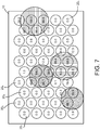
- FIG. 7 shows 4 pots placed on the cooktop, in particular two of the pots are actually touching each other.
- FIG. 8 shows the separate groups of coils used to determine the local maxima, in either the simple case where a single coil represents a local maximum of the coverage factor, and the more complex case with a contiguous region of coils having the same value, within a predefined threshold.
- FIG. 9 shows the actual location of the local maxima, calculated from the groups of coils identified and shown in FIG. 8 .
- FIG. 10 shows, for each coil whose coverage factor exceeds a predefined threshold, which is the closest local maxima.
- a predefined threshold which is the closest local maxima.
- the distance is calculated from the center of each coil to the location of the local maxima. All the coils which are shown as connected to the same local maxima will then be grouped in the same cluster.
- FIG. 11 finally shows the coil clusters, as determined in FIG.10 , with the corresponding estimated cookware items.
- the system can use this information to display a visual representation of the cookware items on the user interface 104.
- the user can then select a first power level input for at least one of the identified cookware items, said first power level input being set by a user through the user interface 104, or any other means.
- the system will then assign a second power level to each coil belonging to a cluster derived from the first power level input received from the user, said second power level being determined and set by the controller; this second power level can be set in many different ways.
- a non-limiting example is to divide the first power level equally among all the coils belonging to the cluster, for example if the first power level is 1200 W and the cluster is composed of 6 coils, the second power level for each coil would be 200 W.
- Another non-limiting example would be to determine the second power level proportionally to the coverage factor. Other criteria are easily determinable by people skilled in the art.
- the system will control the power delivery to the coils belonging to the identified coil cluster corresponding to the selected cookware item, in order to deliver the first power level requested by the user to the selected cookware item.
- clustering of coils allows to discriminate between adjacent cookware items directly, with no need to further process an area previously identified as it happens e.g. in the case of EP2242328 and EP2112865 .
- the term "coupled” in all of its forms, couple, coupling, coupled, etc. generally means the joining of two components (electrical or mechanical) directly or indirectly to one another. Such joining may be stationary in nature or movable in nature. Such joining may be achieved with the two components (electrical or mechanical) and any additional intermediate members being integrally formed as a single unitary body with one another or with the two components. Such joining may be permanent in nature or may be removable or releasable in nature unless otherwise stated.
- elements shown as integrally formed may be constructed of multiple parts or elements shown as multiple parts may be integrally formed, the operation of the interfaces may be reversed or otherwise varied, the length or width of the structures and/or members or connector or other elements of the system may be varied, the nature or number of adjustment positions provided between the elements may be varied.
- the elements and/or assemblies of the system may be constructed from any of a wide variety of materials that provide sufficient strength or durability, in any of a wide variety of colors, textures, and combinations. Accordingly, all such modifications are intended to be included within the scope of the present innovations. Other substitutions, modifications, changes, and omissions may be made in the design, operating conditions, and arrangement of the desired and other exemplary embodiments without departing from the spirit of the present innovations.
- a method of identifying cookware items placed on top of an induction cooktop having a plurality of coils includes the following steps: a) collect information related to a coverage factor indicative of a degree of overlap between a cookware item and a coil for each coil and store it into a coverage factor matrix; b) identify one or more local maxima in the coverage factor matrix, wherein said local maxima correspond to the coverage factor of one or more coils that is or are higher than the coverage factors of adjacent coils; c) identify coordinates of each of the local maxima as follows, wherein said coordinates are referred to a geometric coordinate system of said induction cooktop: i.
- the coordinates are those of a center of a single coil, and ii. when the local maxima is associated with a region of contiguous coils, the coordinates are those of a centroid of the region; d) calculate distances from each coil to each of the coordinates of the identified local maxima; e) for each coil, determine a minimum among the distances; f) group the coils in clusters, based on the distances from the local maxima; and g) use the coil clusters to estimate the position, shape, size, and orientation of the cookware items.
- step d) includes calculating the distance from a center of each coil to the coordinates of the identified local maxima.
- the position estimated at step g) corresponds to the coordinates of the centroid of the cluster of coils.
- the size of a cookware item estimated at step g) is calculated based on a sum the areas of all coils belonging to a cluster, said sum being weighted by using the coverage factors of the coils belonging to said cluster.
- step g) entails calculating with respect to the geometric coordinate system of the induction cooktop: the second moments of area and the product of inertia of each cluster; the principal moments and their angles of rotation; the major and minor semiaxes of the cookware item.
- estimation of the shape at step g) is based on a ratio between the major and minor semiaxes of the cookware item.
- estimation of the orientation of a cookware item is based on said angle of rotation.
- the method further includes the following steps: h) receiving a first power level input for at least one of the identified cookware items, said first power level input being set by a user through a user interface; i) assigning a second power level to each coil belonging to a cluster derived from the first power level input received at step h), said second power level being determined and set by the controller; and j) controlling power delivery to the identified coil clusters associated with each cookware item.
- the method further includes a step of displaying identified cookware items on a user interface.
- the user interface is adapted to display at least one among the position, size, shape and orientation of the cookware.
- the system further includes the step of h) supplying power to the coils underlying the cookware items.
- step b) includes identifying all local maxima in the coverage factor matrix by comparing the coverage factor of each coil with that of all adjacent coils.
- step b) includes identifying all local maxima in the coverage factor matrix by comparing the coverage factor of each coil with that of all adjacent coils.
- the method further includes the step of h) supplying power to the coils underlying the cookware items.
- step b) includes identifying all local maxima in the coverage factor matrix by comparing the coverage factor of each coil with that of all adjacent coils.
Landscapes
- Physics & Mathematics (AREA)
- Electromagnetism (AREA)
- Induction Heating Cooking Devices (AREA)
- Cookers (AREA)
Abstract
Description
- The present disclosure generally relates to a system and method for identifying cookware items placed on an induction cooktop.
- According to one aspect of the present disclosure, a method is provided for identifying cookware items placed on top of an induction cooktop having a plurality of coils, comprising the following steps: a) acquire information related to the coverage factor for each coil and collect it into a coverage factor matrix; b) identify all local maxima in the coverage factor matrix; c) find the coordinates of each of the local maxima as follows: i) when the local maxima is a single coil, the coordinates are those of a center of a single coil, and ii) when the local maxima is a region of contiguous coils, the coordinates are those of a centroid of the region; d) calculate distances from each coil to each of the coordinates of the identified local maxima; e) for each coil, determine a minimum among the distances; f) classify the coils in clusters, based on the distances from the local maxima; and g) use the identified coil clustering to estimate the position, shape, size, and orientation of the cookware items.
- According to another aspect of the present disclosure, an induction cooktop system is provided comprising: an induction cooktop including a plurality of inductive coils; a power supply for supplying power to selected ones of the plurality of inductive coils; and a controller for identifying cookware items placed on top of the induction cooktop, estimating the position, shape, size, and orientation of the cookware items, and controlling the amount of power supplied to the selected ones of the plurality of inductive coils, the controller being programmed to perform at least the following steps: a) acquire information related to the coverage factor for each coil and collect it into a coverage factor matrix; b) identify all local maxima in the coverage factor matrix; c) find the coordinates of each of the local maxima as follows: i) when the local maxima is a single coil, the coordinates are those of a center of a single coil, and ii) when the local maxima is a region of contiguous coils, the coordinates are those of a centroid of the region; d) calculate distances from each coil to each of the coordinates of the identified local maxima; e) for each coil, determine a minimum among the distances; f) classify the coils in clusters, based on the distances from the local maxima; and g) use the identified coil clustering to estimate the position, shape, size, and orientation of the cookware items.
- According to yet another aspect of the present disclosure, a method is provided for identifying cookware items placed on top of an induction cooktop having a plurality of coils, comprising the following steps: a) acquire information related to the coverage factor for each coil and collect it into a coverage factor matrix; b) identify all local maxima in the coverage factor matrix; c) find the coordinates of each of the local maxima as follows: i) when the local maxima is a single coil, the coordinates are those of a center of a single coil, and ii) when the local maxima is a region of contiguous coils, calculating the coordinates of a centroid of the region using the formulas:


- These and other features, advantages, and objects of the present disclosure will be further understood and appreciated by those skilled in the art by reference to the following specification, claims, and appended drawings.
- In the drawings:
-
FIG. 1 is a top view of an induction cooktop having an array of coils; -
FIG. 2A is a top view of the induction cooktop ofFIG. 1 shown with two cookware items thereon with the coverage factors of each coil indicated; -
FIG. 2B is a top view of the induction cooktop ofFIG. 1 shown with an incorrect estimate of the size, shape, orientation, and position of the cookware items shown inFIG. 2A ; -
FIG. 3 is an electrical circuit diagram in block form of an induction cooktop system using the induction cooktop ofFIG. 1 ; -
FIG. 4 is a flow chart of an algorithm executed by the controller inFIG. 3 ; -
FIG. 5 is a top view of the induction cooktop ofFIG. 1 showing neighboring coils; -
FIG. 6A is a top view of the induction cooktop ofFIG. 1 shown with local maxima identified; -
FIG. 6B is a top view of the induction cooktop ofFIG. 1 shown with centroids of the local maxima identified; -
FIG. 6C is a top view of the induction cooktop ofFIG. 1 shown with a correct estimate of the size, shape, orientation, and position of the cookware items shown inFIG. 2A ; -
FIG. 7 is a top view of the induction cooktop ofFIG. 1 shown with four cookware items thereon with the coverage factors of each coil indicated; -
FIG. 8 is a top view of the induction cooktop ofFIG. 1 shown with the groups of coils used for the determination of the local maxima; -
FIG. 9 is a top view of the induction cooktop ofFIG. 1 shown with centroids of the local maxima identified; -
FIG. 10 is a top view of the induction cooktop ofFIG. 1 shown with the association of each coil with the closest local maxima for the determination of the clusters; and -
FIG. 11 is a top view of the induction cooktop ofFIG. 1 shown with the coil clusters and the corresponding estimation of the cookware items. - The components in the figures are not necessarily to scale, emphasis instead being placed upon illustrating the principles described herein.
- The present illustrated embodiments reside primarily in combinations of method steps and apparatus components related to an induction cooktop. Accordingly, the apparatus components and method steps have been represented, where appropriate, by conventional symbols in the drawings, showing only those specific details that are pertinent to understanding the embodiments of the present disclosure so as not to obscure the disclosure with details that will be readily apparent to those of ordinary skill in the art having the benefit of the description herein. Further, like numerals in the description and drawings represent like elements.
- For purposes of description herein, the terms "upper," "lower," "right," "left," "rear," "front," "vertical," "horizontal," and derivatives thereof shall relate to the disclosure as oriented in
FIG. 1 . Unless stated otherwise, the term "front" shall refer to the surface of the element closer to an intended viewer, and the term "rear" shall refer to the surface of the element further from the intended viewer. However, it is to be understood that the disclosure may assume various alternative orientations, except where expressly specified to the contrary. It is also to be understood that the specific devices and processes illustrated in the attached drawings, and described in the following specification are simply exemplary embodiments of the inventive concepts defined in the appended claims. Hence, specific dimensions and other physical characteristics relating to the embodiments disclosed herein are not to be considered as limiting, unless the claims expressly state otherwise. - The terms "including," "comprises," "comprising," or any other variation thereof, are intended to cover a non-exclusive inclusion, such that a process, method, article, or apparatus that comprises a list of elements does not include only those elements but may include other elements not expressly listed or inherent to such process, method, article, or apparatus. An element preceded by "comprises a ..." does not, without more constraints, preclude the existence of additional identical elements in the process, method, article, or apparatus that comprises the element.
- The method described below aims at determining the position, size, shape, and orientation of a number of cookware items such as pots, placed over a flexible induction cooktop. This information can be later used in order to display, on a user interface, the cookware items recognized by the system, so that the user can select a desired first power level for each cookware item. Furthermore, the system can use the first power level selected by the user to derive a second power level for each coil belonging to a cluster associated with the corresponding cookware item, in order to control the power delivered to each of the said coils.
FIG. 1 shows aninduction cooktop 10 characterized by having a large number of coils 201-20n, whose dimensions are typically smaller than the size of a cookware item, and these coils 201-20n are distributed next to each other to form mono-dimensional or bi-dimensional arrays. - When conventional cookware item detection techniques are applied to each individual coil 201-20n, either a discrete YES/NO or a continuous coverage factor information is available for each coil 201-20n, but unfortunately this information is not sufficient to determine the number, position, size, shape, and orientation of cookware items laid over the
induction cooktop 10. - Regarding conventional pan detection techniques,
ES2362839 EP2242328 from Bosch Siemens essentially proposes to generate a first image whose "pixels" are representing the coverage factor in response of the overlying pots. Then it proposes to identify a cohesive (i.e. contiguous) area made of neighboring cells having a coverage factor larger than a predetermined threshold. Finally, it is proposed to apply a separation algorithm aimed at differentiating whether the contiguous area corresponds to one pot or to multiple pots close to each other. The proposed method inES2362839 EP2242328 is known to provide inaccurate results whenever the heating cell dimension is not sufficiently small compared to the size of the pot. - It is also known to first determine a cell covered by a pot and then perform a selective search in a neighborhood of that cell, through a set of additional sensors. An example of this method is disclosed in
EP2112865 . -
FIG. 2A showsactual cookware items flexible induction cooktop 10.FIG. 2B shows a singleelliptical pot 34 is incorrectly identified instead of two circular ones, since thecookware items cookware items oval pot 34. The objective of the present method is to provide a method for cookware item identification and estimation able to identifyindividual cookware items -
FIG. 3 shows a block diagram of the basic electrical components of an induction cooktop system 5. Acontroller 100, such as a microprocessor or the like, is coupled to each of the coils 201-20n of theinduction cooktop 10 and to apower supply 102 and auser interface 104. In general, thecontroller 100 will respond to activation of an input on theuser interface 104 to detect the presence, size, shape, orientation, and position of anycookware items induction cooktop 10 using the method described below. Once the size, shape, orientation, and position of anycookware items controller 100 will control thepower supply 102 to supply an appropriate power level to the coils 201-20n underlying thecookware items cookware items - The
user interface 104 may be any conventional user interface and may include various inputs such as temperature settings and timers or the like. - A
method 200 described herein is shown inFIG. 4 and may be implemented as an algorithm executed by thecontroller 100. Themethod 200 has apreliminary step 202 in the acquisition of a matrix of information related to the coverage factors, each element of the matrix corresponding to one coil 201-20n. The particular manner in which thecontroller 100 determines the coverage factor of each coil 201-20n is not described herein insofar as any known technique may be used. The coverage factor matrix is then processed according to the described method to identify the different cookware items. - The coverage factor for each coil is defined as the degree of coverage of the coil when coupled to an overlying cookware item. This coverage factor for each of the coils can be derived through a pan detection system and particularly by measuring the electromagnetic coupling between the coil and the overlying cookware. In this case, to each of the inductors can be assigned a value indicative of the coverage, for instance a percentage value, starting from an electrical measurable variable linked with the electromagnetic coupling of the inductor in question, with one or more of the overlying cookware items. The electrical variable that can be preferably measured is the complex impedance at the leads of the coil. It is also understood that other information related to the coverage factor can be used instead, such as, but not limited to, inductance, resistance, or power factor.
- However, any other variable linked with the fraction of the area of the coil that is covered by an overlying cookware item, can also be used as a coverage factor.
- From the above it follows that collect information related to a coverage factor thus means to collect information indicative of a degree of overlap between a cookware item and coil, and preferably to measure one or more electrical variables related to the electromagnetic coupling between the overlying cookware item and the coil; In
FIG. 2 and following, this fraction is expressed as a percentage. - This
method 200 may be referred to herein as a pseudoVoronoi method that is based on the Voronoi diagram for the partition of the plane into distinct regions: given a predetermined group of starting points called seeds, for each seed there is a region comprising all points in the plane closer to that seed than to any other. - The
method 200 presupposes that the coverage factors of the coils 201-20n have already been acquired, and therefore takes as input a coverage factor matrix containing the coverage factors of each individual coil 201-20n in theinduction cooktop 10 instep 202. As described further below, themethod 200 uses the local maxima of the coverage factor matrix as starting points, and clusters the coils 201-20n in regions closest to each of the local maxima. The coverage factor is indicative of a degree of overlap or electrical coupling between acookware item - The surface of the
cooktop 10 is associated with a coordinate system apt to describe a 2D surface, for example, but not limited to, a Cartesian coordinate system with origin in the lower left corner of the cooktop surface, with the x axis oriented horizontally towards the right and the y axis oriented vertically towards the back. - The
next step 204 of the algorithm is the identification of the local maxima in the coverage factor matrix, carried out by comparing the coverage factor of each coil 201-20n with that of all adjacent coils 201-20n. It is important to remember that the coverage factor is stored in the coverage factor matrix for ease of processing, and does not reflect the physical arrangement of the coils 201-20n; therefore, adjacent coils 201-20n are not simply those neighboring in the same column or row in the coverage factor matrix, but one may take into account the so-called adjacency matrix. The adjacency matrix describes, for each pair of coils 201-20n, whether they are adjacent or not, and depends only on the geometry of theinduction cooktop 10 and the arrangement of the coils 201-20n, and is therefore fixed from the point of view of the algorithm. In particular, for the current geometry the adjacency matrix describes a triangular grid, in which each coil 201-20n is, in general, adjacent to its six closest neighbors, as shown inFIG. 5 . For coils 201-20n placed near the side or on the corner, the number of adjacent neighbors is lower. - In
FIG. 5 , each coil 201-20n indicated by a large dot is adjacent to its, at most, six closest neighbors, indicated by the smaller dots and connected via line segments. Coils 201-20n on the sides or on the corners have fewer adjacent neighbors. - In the simplest case, a local maximum corresponds to the coverage factor of one coil that is higher than to the coverage factors of its adjacent coils 201-20n. In more complex cases, it is possible that two or more adjacent coils 201-20n all have the same coverage factor, while all remaining adjacent coils have a lower coverage factor; in actual embodiments, a predefined tolerance band around the maximum coverage factor is used in order to take into consideration coils whose coverage factor might be lower than the maximum due to tolerances, electrical noise, and the like. In this situation, it is necessary to first identify all the coils 201-20n that have the corresponding coverage factor, or whose coverage factors fall into the aforementioned tolerance band, and that form a single, contiguous region. For instance, the tolerance band could be in the order of 5 %. This distinction is used in the calculation of the coordinates of the local maxima. In other words, when the coverage factors of adjacent coils 201-20n are within a predefined range, i.e. in the tolerance band above, the region of contiguous coils of step comprises said coils 201-20n. An example of the two cases is shown in
FIG. 6A : the simple case on the left, and the more complex case on the right. - The algorithm then calculates the coordinate of each local maximum in
step 206. In the simple case listed above, the local maximum coordinates are simply those of the center of the corresponding coil 201-20n. In the other case, the coordinates are calculated as those of the centroid of the identified contiguous region, using the formulas:

FIG. 6B , where the larger dots represent the calculated centroids for each local maximum. - Once the local maxima have been identified and their coordinates calculated, they are treated as the seeds of the Voronoi partition of the plane; in a non-limiting example, the partition considers only the coil centers as points to be clustered. To do that, in
step 208 the algorithm calculates, for each coil, the distance between its center and each of the local maxima identified instep 206. The minimum distance is identified instep 210, and each coil is assigned to the closest identified local maximum, thus clustering the coils into distinct groups around the local maxima instep 212. An example is shown inFIG. 6C . - In the particular example shown, the
controller 100 identifies twodifferent coil clusters coil cluster cookware items induction cooktop 10, indicated by the thick-bordered circles. Each cluster ofcoil clusters cookware items step 214. - For each cluster, the centroid is identified by calculating the weighted sum of the coordinates of the centers of all the coils belonging to said cluster, wherein the weights are the coverage factors of each coil:


- In order to estimate the size of each cookware item, one possible way is to first calculate the weighted area of the corresponding cluster. One possible way of performing this calculation is to sum the areas of all coils belonging to the cluster, adjusted by a factor the takes into account the empty areas between coils, weighted by the corresponding coverage factors:


- Another possible way to estimate the size of each cookware item, is first calculate the second moments of area and the product of inertia. One possible way of performing this calculation is to consider cartesian axes, passing through the center of the cookware item, and parallel to the axes of the reference coordinate system defined in §0036. The moments can be calculated as:


- Next step is to calculate the principal moments and the angle of rotation; the principal moments are oriented along the main directions of the shape, and can be calculated as:


- Finally, using the calculated principal moments, it is possible to estimate the major and minor semiaxes of the cookware item, in case the cookware item is elliptical:


- A typical method to estimate the shape is to consider the ratio between the two semiaxes a and b just calculated: if the two values of a and b are the same, the ratio is 1 and the shape is circular; if they are different, the ratio is other than 1 and the shape is elliptical. Due to the uncertainty in the estimation and calculation of the values of the major and minor semiaxes, it is typical to compare the ratio a/b with a predefined threshold, and if the ratio is larger than this threshold consider the shape as elliptical, whereas if the ratio is smaller than this threshold the shape is considered as circular.
- For efficiency reasons, it may be advantageous to limit this process to coils whose coverage factor is higher than a predefined threshold, since coils with a small coverage factor would have a negligible contribution either to the identification of the position, shape, size, and orientation of a cookware item, or to the heating of the cookware item itself.
- In the following paragraphs, another example of the method operation is detailed, applied to the pots placed on top of the cooktop as shown in
FIG. 7. FIG. 7 shows 4 pots placed on the cooktop, in particular two of the pots are actually touching each other. -
FIG. 8 shows the separate groups of coils used to determine the local maxima, in either the simple case where a single coil represents a local maximum of the coverage factor, and the more complex case with a contiguous region of coils having the same value, within a predefined threshold. -
FIG. 9 shows the actual location of the local maxima, calculated from the groups of coils identified and shown inFIG. 8 . -
FIG. 10 shows, for each coil whose coverage factor exceeds a predefined threshold, which is the closest local maxima. In this case, as a non-limiting example, the distance is calculated from the center of each coil to the location of the local maxima. All the coils which are shown as connected to the same local maxima will then be grouped in the same cluster. -
FIG. 11 finally shows the coil clusters, as determined inFIG.10 , with the corresponding estimated cookware items. - Once the geometrical characteristics of the cookware item have been estimated, namely center position, shape, size, and orientation, the system can use this information to display a visual representation of the cookware items on the
user interface 104. - The user can then select a first power level input for at least one of the identified cookware items, said first power level input being set by a user through the
user interface 104, or any other means. - The system will then assign a second power level to each coil belonging to a cluster derived from the first power level input received from the user, said second power level being determined and set by the controller; this second power level can be set in many different ways. A non-limiting example is to divide the first power level equally among all the coils belonging to the cluster, for example if the first power level is 1200 W and the cluster is composed of 6 coils, the second power level for each coil would be 200 W. Another non-limiting example would be to determine the second power level proportionally to the coverage factor. Other criteria are easily determinable by people skilled in the art.
- Finally, the system will control the power delivery to the coils belonging to the identified coil cluster corresponding to the selected cookware item, in order to deliver the first power level requested by the user to the selected cookware item.
-
- It will be understood by one having ordinary skill in the art that construction of the described disclosure and other components is not limited to any specific material. Other exemplary embodiments of the disclosure disclosed herein may be formed from a wide variety of materials, unless described otherwise herein.
- For purposes of this disclosure, the term "coupled" (in all of its forms, couple, coupling, coupled, etc.) generally means the joining of two components (electrical or mechanical) directly or indirectly to one another. Such joining may be stationary in nature or movable in nature. Such joining may be achieved with the two components (electrical or mechanical) and any additional intermediate members being integrally formed as a single unitary body with one another or with the two components. Such joining may be permanent in nature or may be removable or releasable in nature unless otherwise stated.
- It is also important to note that the construction and arrangement of the elements of the disclosure as shown in the exemplary embodiments is illustrative only. Although only a few embodiments of the present innovations have been described in detail in this disclosure, those skilled in the art who review this disclosure will readily appreciate that many modifications are possible (e.g., variations in sizes, dimensions, structures, shapes and proportions of the various elements, values of parameters, mounting arrangements, use of materials, colors, orientations, etc.) without materially departing from the novel teachings and advantages of the subject matter recited. For example, elements shown as integrally formed may be constructed of multiple parts or elements shown as multiple parts may be integrally formed, the operation of the interfaces may be reversed or otherwise varied, the length or width of the structures and/or members or connector or other elements of the system may be varied, the nature or number of adjustment positions provided between the elements may be varied. It should be noted that the elements and/or assemblies of the system may be constructed from any of a wide variety of materials that provide sufficient strength or durability, in any of a wide variety of colors, textures, and combinations. Accordingly, all such modifications are intended to be included within the scope of the present innovations. Other substitutions, modifications, changes, and omissions may be made in the design, operating conditions, and arrangement of the desired and other exemplary embodiments without departing from the spirit of the present innovations.
- According to a first aspect of the present disclosure, a method of identifying cookware items placed on top of an induction cooktop having a plurality of coils, includes the following steps: a) collect information related to a coverage factor indicative of a degree of overlap between a cookware item and a coil for each coil and store it into a coverage factor matrix; b) identify one or more local maxima in the coverage factor matrix, wherein said local maxima correspond to the coverage factor of one or more coils that is or are higher than the coverage factors of adjacent coils; c) identify coordinates of each of the local maxima as follows, wherein said coordinates are referred to a geometric coordinate system of said induction cooktop: i. when the local maxima is associated with a single coil, the coordinates are those of a center of a single coil, and ii. when the local maxima is associated with a region of contiguous coils, the coordinates are those of a centroid of the region; d) calculate distances from each coil to each of the coordinates of the identified local maxima; e) for each coil, determine a minimum among the distances; f) group the coils in clusters, based on the distances from the local maxima; and g) use the coil clusters to estimate the position, shape, size, and orientation of the cookware items.
- According to the first aspect of the present disclosure, step d) includes calculating the distance from a center of each coil to the coordinates of the identified local maxima.
- According the first aspect or any single or combination of intervening aspects of the present disclosure, step c)ii) includes calculating the coordinates of the centroid of the region using the formulas:


- According to the first aspect or any single or combination of intervening aspects of the present disclosure, the position estimated at step g) corresponds to the coordinates of the centroid of the cluster of coils.
- According to the first aspect or any single or combination of intervening aspects of the present disclosure, the size of a cookware item estimated at step g) is calculated based on a sum the areas of all coils belonging to a cluster, said sum being weighted by using the coverage factors of the coils belonging to said cluster.
- According to the first aspect or any single or combination of intervening aspects of the present disclosure, step g) entails calculating with respect to the geometric coordinate system of the induction cooktop: the second moments of area and the product of inertia of each cluster; the principal moments and their angles of rotation; the major and minor semiaxes of the cookware item.
- According to the first aspect or any single or combination of intervening aspects of the present disclosure, estimation of the shape at step g) is based on a ratio between the major and minor semiaxes of the cookware item.
- According to the first aspect or any single or combination of intervening aspects of the present disclosure, estimation of the orientation of a cookware item is based on said angle of rotation.
- According to the first aspect or any single or combination of intervening aspects of the present disclosure, the method further includes the following steps: h) receiving a first power level input for at least one of the identified cookware items, said first power level input being set by a user through a user interface; i) assigning a second power level to each coil belonging to a cluster derived from the first power level input received at step h), said second power level being determined and set by the controller; and j) controlling power delivery to the identified coil clusters associated with each cookware item.
- According to the first aspect or any single or combination of intervening aspects of the present disclosure, the method further includes a step of displaying identified cookware items on a user interface.
- According to a second aspect of the present disclosure, an induction cooktop system includes: an induction cooktop including a plurality of inductive coils; a power supply for supplying power to selected ones of the plurality of inductive coils; and a controller configured to perform the following steps: a) collect information related to a coverage factor indicative of a degree of overlap between a cookware item and a coil for each coil and store it into a coverage factor matrix; b) identify one or more local maxima in the coverage factor matrix, wherein said local maxima correspond to the coverage factor of one or more coils that is or are higher than the coverage factors of adjacent coils; c) identify coordinates of each of the local maxima as follows, wherein said coordinates are referred to a geometric coordinate system of said induction cooktop: i. when the local maxima is associated with a single coil, the coordinates are those of a center of a single coil, and ii. when the local maxima is associated with a region of contiguous coils, the coordinates are those of a centroid of the region; d) calculate distances from each coil to each of the coordinates of the identified local maxima; e) for each coil, determine a minimum among the distances; f) group the coils in clusters, based on the distances from the local maxima; and g) use the coil clusters to estimate the position, shape, size, and orientation of the cookware items.
- According to the second aspect of the present disclosure, the user interface is adapted to display at least one among the position, size, shape and orientation of the cookware.
- According to the second aspect or any single or combination of intervening aspects of the present disclosure, the system further includes the step of h) supplying power to the coils underlying the cookware items.
- According to the second aspect or any single or combination of intervening aspects of the present disclosure, step b) includes identifying all local maxima in the coverage factor matrix by comparing the coverage factor of each coil with that of all adjacent coils.
- According to the second aspect or any single or combination of intervening aspects of the present disclosure, step b) includes identifying all local maxima in the coverage factor matrix by comparing the coverage factor of each coil with that of all adjacent coils.
- According to a third aspect of the present disclosure, a method of identifying cookware items placed on top of an induction cooktop having a plurality of coils, includes the following steps: a) acquire coverage factor information for each coil and collect it into a coverage factor matrix; b) identify all local maxima in the coverage factor matrix; c) find the coordinates of each of the local maxima as follows: i) when the local maxima is a single coil, the coordinates are those of a center of a single coil, and ii) when the local maxima is a region of contiguous coils, calculating the coordinates of a centroid of the region using the formulas:


- According to the third aspect of the present disclosure, the method further includes the step of h) supplying power to the coils underlying the cookware items.
- According to the third aspect or any single or combination of intervening aspects of the present disclosure, step b) includes identifying all local maxima in the coverage factor matrix by comparing the coverage factor of each coil with that of all adjacent coils.
- It will be understood that any described processes or steps within described processes may be combined with other disclosed processes or steps to form structures within the scope of the present disclosure. The exemplary structures and processes disclosed herein are for illustrative purposes and are not to be construed as limiting.
Claims (13)
- A method of identifying cookware items (30, 32, 34) placed on top of an induction cooktop (10) having a plurality of coils (201-20n), comprising the following steps:a) collect information related to a coverage factor indicative of a degree of overlap between a cookware item (30, 32, 34) and a coil (201-20n) for each coil (201-20n) and store it into a coverage factor matrix;b) identify one or more local maxima in the coverage factor matrix, wherein said local maxima correspond to the coverage factor of one or more coils (201-20n) that is or are higher than the coverage factors of adjacent coils (201-20n);c) identify coordinates of each of the local maxima as follows, wherein said coordinates are referred to a geometric coordinate system of said induction cooktop (10):i. when the local maxima is associated with a single coil (201-20n), the coordinates are those of a center of a single coil (201-20n), andii. when the local maxima is associated with a region of contiguous coils (201-20n), the coordinates are those of a centroid of the region;d) calculate distances from each coil (201-20n) to each of the coordinates of the identified local maxima;e) for each coil (201-20n), determine a minimum among said distances;f) define clusters of coils, wherein each cluster is associated to a local maximum, and wherein each cluster contains coils (201-20n) whose distance from said local maximum has been identified as the minimum distance in step (e); andg) use the coil clusters to estimate at least one of position, shape, size, and orientation of the cookware items (30, 32, 34).
- The method of claim 1, wherein, when the coverage factors of adjacent coils (201-20n) are within a predefined range, the region of contiguous coils of step c)ii) comprises said coils (201-20n).
- The method of claim 1 or 2, wherein step d) includes calculating the distance from a center of each coil (201-20n) to the coordinates of the identified local maxima.
- The method of claim 1, wherein step c)ii) includes calculating the coordinates of the centroid of the region using the formulas:

 xc , yc are the coordinates of the centroid,N is the number of coils (201-20n) considered in the calculation for this particular centroid, xi , yi are the coordinates of the ith coil (201-20n), andci is a quantity proportional to the the coverage factor for the ith coil (201-20n).
 - The method of any one of claims 4, wherein the position estimated at step g) corresponds to the coordinates of the centroid of the cluster of coils (201-20n).
- The method of any one of claims 1-5, wherein the size of a cookware item (30, 32, 34) estimated at step g) is calculated based on a sum the areas of all coils (201-20n) belonging to a cluster, said sum being weighted by using the coverage factors of the coils (201-20n) belonging to said cluster.
- The method of any one of claims 1-6, wherein step g) entails calculating with respect to the geometric coordinate system of the induction cooktop (10):- the second moments of area and the product of inertia of each cluster;- the principal moments and their angles of rotation;- the major and minor semiaxes of the cookware item (30, 32, 34).
- The method of claim 7, wherein estimation of the shape at step g) is based on a ratio between the major and minor semiaxes of the cookware item (30, 32, 34).
- The method of claim 7 or 8, wherein estimation of the orientation of a cookware item (30, 32, 34) is based on said angle of rotation.
- The method of any one of claims 1-9, further comprising the following steps:h) receiving a first power level input for at least one of the identified cookware items (30, 32, 34), said first power level input being set by a user through a user interface (104);i) assigning a second power level to each coil (201-20n) belonging to a cluster, said second power level deriving from the first power level input received at step h) and being determined and set by a controller (100); andj) controlling power delivery to the identified coil clusters associated with each cookware item (30, 32, 34).
- The method of any one of the preceding claims, further comprising a step of displaying identified cookware items (30, 32, 34) on a user interface (104).
- An induction cooktop system (5) comprising:an induction cooktop (10) including a plurality of inductive coils (201-20n);a power supply (102) for supplying power to selected ones of the plurality of inductive coils (201-20n); anda controller (100) configured to carry out the method of any one of the preceding claims.
- The induction cooktop system (5) of claim 12, wherein the user interface (104) is adapted to display at least one among the position, size, shape and orientation of the cookware items (30, 32, 34), as identified through the method of claim 1.
Applications Claiming Priority (2)
| Application Number | Priority Date | Filing Date | Title |
|---|---|---|---|
| US16/946,101 US11596030B2 (en) | 2020-06-05 | 2020-06-05 | System and method for identifying cookware items placed on an induction cooktop |
| US16/946,098 US12058797B2 (en) | 2020-06-05 | 2020-06-05 | System and method for identifying cookware items placed on an induction cooktop |
Publications (2)
| Publication Number | Publication Date |
|---|---|
| EP3920662A1 true EP3920662A1 (en) | 2021-12-08 |
| EP3920662B1 EP3920662B1 (en) | 2026-03-11 |
Family
ID=76283653
Family Applications (2)
| Application Number | Title | Priority Date | Filing Date |
|---|---|---|---|
| EP21177817.0A Active EP3920662B1 (en) | 2020-06-05 | 2021-06-04 | System and method for identifying cookware items placed on an induction cooktop |
| EP21177841.0A Active EP3920663B1 (en) | 2020-06-05 | 2021-06-04 | System and method for identifying cookware items placed on an induction cooktop |
Family Applications After (1)
| Application Number | Title | Priority Date | Filing Date |
|---|---|---|---|
| EP21177841.0A Active EP3920663B1 (en) | 2020-06-05 | 2021-06-04 | System and method for identifying cookware items placed on an induction cooktop |
Country Status (1)
| Country | Link |
|---|---|
| EP (2) | EP3920662B1 (en) |
Cited By (1)
| Publication number | Priority date | Publication date | Assignee | Title |
|---|---|---|---|---|
| CN115685376A (en) * | 2022-09-06 | 2023-02-03 | 佛山市爱庭电器有限公司 | An electromagnetic heating positioning system, positioning method and storage medium |
Citations (3)
| Publication number | Priority date | Publication date | Assignee | Title |
|---|---|---|---|---|
| EP2112865A2 (en) | 2003-11-27 | 2009-10-28 | Fagorbrandtsas | Method for heating a container placed on a hob with heating means connected to induction units |
| EP2242328A2 (en) | 2009-04-17 | 2010-10-20 | BSH Bosch und Siemens Hausgeräte GmbH | Method for detecting cooking cutlery on a matrix hob |
| EP2242329B1 (en) * | 2009-04-14 | 2015-07-29 | BSH Hausgeräte GmbH | Hotplate and method for operating a hotplate |
Family Cites Families (2)
| Publication number | Priority date | Publication date | Assignee | Title |
|---|---|---|---|---|
| ES2324450B1 (en) | 2007-08-07 | 2010-05-25 | Bsh Electrodomesticos España, S.A. | COOKING FIELD WITH A SENSOR DEVICE AND PROCEDURE FOR THE DETECTION OF COOKING BATTERY ON A COOKING FIELD. |
| ES2730394T3 (en) * | 2016-10-10 | 2019-11-11 | Ego Elektro Geraetebau Gmbh | Method for controlling an induction cooking hob and induction cooking hob |
-
2021
- 2021-06-04 EP EP21177817.0A patent/EP3920662B1/en active Active
- 2021-06-04 EP EP21177841.0A patent/EP3920663B1/en active Active
Patent Citations (3)
| Publication number | Priority date | Publication date | Assignee | Title |
|---|---|---|---|---|
| EP2112865A2 (en) | 2003-11-27 | 2009-10-28 | Fagorbrandtsas | Method for heating a container placed on a hob with heating means connected to induction units |
| EP2242329B1 (en) * | 2009-04-14 | 2015-07-29 | BSH Hausgeräte GmbH | Hotplate and method for operating a hotplate |
| EP2242328A2 (en) | 2009-04-17 | 2010-10-20 | BSH Bosch und Siemens Hausgeräte GmbH | Method for detecting cooking cutlery on a matrix hob |
Cited By (1)
| Publication number | Priority date | Publication date | Assignee | Title |
|---|---|---|---|---|
| CN115685376A (en) * | 2022-09-06 | 2023-02-03 | 佛山市爱庭电器有限公司 | An electromagnetic heating positioning system, positioning method and storage medium |
Also Published As
| Publication number | Publication date |
|---|---|
| EP3920663B1 (en) | 2022-12-28 |
| EP3920663A1 (en) | 2021-12-08 |
| EP3920662B1 (en) | 2026-03-11 |
Similar Documents
| Publication | Publication Date | Title |
|---|---|---|
| US12058797B2 (en) | System and method for identifying cookware items placed on an induction cooktop | |
| EP3273750B1 (en) | Induction heating cooker and control method thereof | |
| EP2211591B1 (en) | Method for operating a hob with a number of heating elements | |
| EP2242328B1 (en) | Method for detecting cookware on a matrix hob | |
| US9307580B2 (en) | Induction heating cooker and control method thereof | |
| CN105455603B (en) | It detects the method for the identity of the pot in the cooking point of stove circle and has the stove circle system of pot | |
| CN104602378B (en) | Electromagnetic oven and control method | |
| EP3920662B1 (en) | System and method for identifying cookware items placed on an induction cooktop | |
| US20120043312A1 (en) | Induction heating cooker and method of controlling the same | |
| US10448461B2 (en) | Cooktop having a plurality of heating elements | |
| CN105071650B (en) | Control method and device of power factor correction circuit and air conditioner | |
| CN113673757B (en) | Intelligent dining room dining rule prediction method and device | |
| KR102474283B1 (en) | A smart induction using non-contact temperature and automatic cooking control system including it | |
| CN109699098B (en) | Electromagnetic heating cooking utensil and method and device for detecting deviation of cookware thereof | |
| US11596030B2 (en) | System and method for identifying cookware items placed on an induction cooktop | |
| NL2020668A (en) | Induction heating plate. | |
| CN108826597A (en) | Control method and device of air conditioning equipment | |
| CN106772346A (en) | The fried point automatic identification technology of one kind | |
| ES2815948T3 (en) | Procedure for detecting at least one cooking zone on a hob | |
| CN116293842A (en) | Method for operating a cooktop and cooktop | |
| CN110332660A (en) | Temperature field data determination method, device and equipment capable of improving temperature field precision | |
| CN119399280A (en) | Method, device, equipment and storage medium for indicating food placement | |
| CN107084411A (en) | Control method of electromagnetic oven cooker | |
| CN111414784A (en) | Method and device for determining water adding level, mobile terminal and storage medium | |
| CN206294364U (en) | Coil panel component and electromagnetic cooking appliance |
Legal Events
| Date | Code | Title | Description |
|---|---|---|---|
| PUAI | Public reference made under article 153(3) epc to a published international application that has entered the european phase |
Free format text: ORIGINAL CODE: 0009012 |
|
| STAA | Information on the status of an ep patent application or granted ep patent |
Free format text: STATUS: THE APPLICATION HAS BEEN PUBLISHED |
|
| AK | Designated contracting states |
Kind code of ref document: A1 Designated state(s): AL AT BE BG CH CY CZ DE DK EE ES FI FR GB GR HR HU IE IS IT LI LT LU LV MC MK MT NL NO PL PT RO RS SE SI SK SM TR |
|
| B565 | Issuance of search results under rule 164(2) epc |
Effective date: 20211022 |
|
| STAA | Information on the status of an ep patent application or granted ep patent |
Free format text: STATUS: REQUEST FOR EXAMINATION WAS MADE |
|
| 17P | Request for examination filed |
Effective date: 20220608 |
|
| RBV | Designated contracting states (corrected) |
Designated state(s): AL AT BE BG CH CY CZ DE DK EE ES FI FR GB GR HR HU IE IS IT LI LT LU LV MC MK MT NL NO PL PT RO RS SE SI SK SM TR |
|
| GRAP | Despatch of communication of intention to grant a patent |
Free format text: ORIGINAL CODE: EPIDOSNIGR1 |
|
| STAA | Information on the status of an ep patent application or granted ep patent |
Free format text: STATUS: GRANT OF PATENT IS INTENDED |
|
| RIC1 | Information provided on ipc code assigned before grant |
Ipc: H05B 6/06 20060101AFI20250602BHEP |
|
| INTG | Intention to grant announced |
Effective date: 20250704 |
|
| GRAJ | Information related to disapproval of communication of intention to grant by the applicant or resumption of examination proceedings by the epo deleted |
Free format text: ORIGINAL CODE: EPIDOSDIGR1 |
|
| STAA | Information on the status of an ep patent application or granted ep patent |
Free format text: STATUS: REQUEST FOR EXAMINATION WAS MADE |
|
| GRAP | Despatch of communication of intention to grant a patent |
Free format text: ORIGINAL CODE: EPIDOSNIGR1 |
|
| STAA | Information on the status of an ep patent application or granted ep patent |
Free format text: STATUS: GRANT OF PATENT IS INTENDED |
|
| INTC | Intention to grant announced (deleted) | ||
| INTG | Intention to grant announced |
Effective date: 20251027 |
|
| GRAS | Grant fee paid |
Free format text: ORIGINAL CODE: EPIDOSNIGR3 |
|
| GRAA | (expected) grant |
Free format text: ORIGINAL CODE: 0009210 |
|
| STAA | Information on the status of an ep patent application or granted ep patent |
Free format text: STATUS: THE PATENT HAS BEEN GRANTED |
|
| AK | Designated contracting states |
Kind code of ref document: B1 Designated state(s): AL AT BE BG CH CY CZ DE DK EE ES FI FR GB GR HR HU IE IS IT LI LT LU LV MC MK MT NL NO PL PT RO RS SE SI SK SM TR |
|
| REG | Reference to a national code |
Ref country code: CH Ref legal event code: F10 Free format text: ST27 STATUS EVENT CODE: U-0-0-F10-F00 (AS PROVIDED BY THE NATIONAL OFFICE) Effective date: 20260311 Ref country code: GB Ref legal event code: FG4D |
|
| REG | Reference to a national code |
Ref country code: DE Ref legal event code: R096 Ref document number: 602021049595 Country of ref document: DE |
|
| REG | Reference to a national code |
Ref country code: IE Ref legal event code: FG4D |
|
| P01 | Opt-out of the competence of the unified patent court (upc) registered |
Free format text: CASE NUMBER: UPC_APP_0010676_3920662/2026 Effective date: 20260323 |