EP3920429A1 - Codebook feedback method, terminal device and network device - Google Patents
Codebook feedback method, terminal device and network device Download PDFInfo
- Publication number
- EP3920429A1 EP3920429A1 EP19917114.1A EP19917114A EP3920429A1 EP 3920429 A1 EP3920429 A1 EP 3920429A1 EP 19917114 A EP19917114 A EP 19917114A EP 3920429 A1 EP3920429 A1 EP 3920429A1
- Authority
- EP
- European Patent Office
- Prior art keywords
- frequency domain
- indication
- dft
- domain dft
- dft vector
- Prior art date
- Legal status (The legal status is an assumption and is not a legal conclusion. Google has not performed a legal analysis and makes no representation as to the accuracy of the status listed.)
- Granted
Links
Images




Classifications
-
- H—ELECTRICITY
- H04—ELECTRIC COMMUNICATION TECHNIQUE
- H04B—TRANSMISSION
- H04B7/00—Radio transmission systems, i.e. using radiation field
- H04B7/02—Diversity systems; Multi-antenna system, i.e. transmission or reception using multiple antennas
- H04B7/04—Diversity systems; Multi-antenna system, i.e. transmission or reception using multiple antennas using two or more spaced independent antennas
- H04B7/0413—MIMO systems
- H04B7/0417—Feedback systems
-
- H—ELECTRICITY
- H04—ELECTRIC COMMUNICATION TECHNIQUE
- H04B—TRANSMISSION
- H04B7/00—Radio transmission systems, i.e. using radiation field
- H04B7/02—Diversity systems; Multi-antenna system, i.e. transmission or reception using multiple antennas
- H04B7/04—Diversity systems; Multi-antenna system, i.e. transmission or reception using multiple antennas using two or more spaced independent antennas
- H04B7/0413—MIMO systems
- H04B7/0456—Selection of precoding matrices or codebooks, e.g. using matrices antenna weighting
- H04B7/0482—Adaptive codebooks
-
- H—ELECTRICITY
- H04—ELECTRIC COMMUNICATION TECHNIQUE
- H04B—TRANSMISSION
- H04B7/00—Radio transmission systems, i.e. using radiation field
- H04B7/02—Diversity systems; Multi-antenna system, i.e. transmission or reception using multiple antennas
- H04B7/04—Diversity systems; Multi-antenna system, i.e. transmission or reception using multiple antennas using two or more spaced independent antennas
- H04B7/0413—MIMO systems
- H04B7/0456—Selection of precoding matrices or codebooks, e.g. using matrices antenna weighting
- H04B7/0478—Special codebook structures directed to feedback optimisation
-
- H—ELECTRICITY
- H04—ELECTRIC COMMUNICATION TECHNIQUE
- H04B—TRANSMISSION
- H04B7/00—Radio transmission systems, i.e. using radiation field
- H04B7/02—Diversity systems; Multi-antenna system, i.e. transmission or reception using multiple antennas
- H04B7/04—Diversity systems; Multi-antenna system, i.e. transmission or reception using multiple antennas using two or more spaced independent antennas
- H04B7/06—Diversity systems; Multi-antenna system, i.e. transmission or reception using multiple antennas using two or more spaced independent antennas at the transmitting station
- H04B7/0613—Diversity systems; Multi-antenna system, i.e. transmission or reception using multiple antennas using two or more spaced independent antennas at the transmitting station using simultaneous transmission
- H04B7/0615—Diversity systems; Multi-antenna system, i.e. transmission or reception using multiple antennas using two or more spaced independent antennas at the transmitting station using simultaneous transmission of weighted versions of same signal
- H04B7/0619—Diversity systems; Multi-antenna system, i.e. transmission or reception using multiple antennas using two or more spaced independent antennas at the transmitting station using simultaneous transmission of weighted versions of same signal using feedback from receiving side
- H04B7/0621—Feedback content
- H04B7/0626—Channel coefficients, e.g. channel state information [CSI]
-
- H—ELECTRICITY
- H04—ELECTRIC COMMUNICATION TECHNIQUE
- H04B—TRANSMISSION
- H04B7/00—Radio transmission systems, i.e. using radiation field
- H04B7/02—Diversity systems; Multi-antenna system, i.e. transmission or reception using multiple antennas
- H04B7/04—Diversity systems; Multi-antenna system, i.e. transmission or reception using multiple antennas using two or more spaced independent antennas
- H04B7/06—Diversity systems; Multi-antenna system, i.e. transmission or reception using multiple antennas using two or more spaced independent antennas at the transmitting station
- H04B7/0613—Diversity systems; Multi-antenna system, i.e. transmission or reception using multiple antennas using two or more spaced independent antennas at the transmitting station using simultaneous transmission
- H04B7/0615—Diversity systems; Multi-antenna system, i.e. transmission or reception using multiple antennas using two or more spaced independent antennas at the transmitting station using simultaneous transmission of weighted versions of same signal
- H04B7/0619—Diversity systems; Multi-antenna system, i.e. transmission or reception using multiple antennas using two or more spaced independent antennas at the transmitting station using simultaneous transmission of weighted versions of same signal using feedback from receiving side
- H04B7/0621—Feedback content
- H04B7/0634—Antenna weights or vector/matrix coefficients
-
- H—ELECTRICITY
- H04—ELECTRIC COMMUNICATION TECHNIQUE
- H04B—TRANSMISSION
- H04B7/00—Radio transmission systems, i.e. using radiation field
- H04B7/02—Diversity systems; Multi-antenna system, i.e. transmission or reception using multiple antennas
- H04B7/04—Diversity systems; Multi-antenna system, i.e. transmission or reception using multiple antennas using two or more spaced independent antennas
- H04B7/06—Diversity systems; Multi-antenna system, i.e. transmission or reception using multiple antennas using two or more spaced independent antennas at the transmitting station
- H04B7/0613—Diversity systems; Multi-antenna system, i.e. transmission or reception using multiple antennas using two or more spaced independent antennas at the transmitting station using simultaneous transmission
- H04B7/0615—Diversity systems; Multi-antenna system, i.e. transmission or reception using multiple antennas using two or more spaced independent antennas at the transmitting station using simultaneous transmission of weighted versions of same signal
- H04B7/0619—Diversity systems; Multi-antenna system, i.e. transmission or reception using multiple antennas using two or more spaced independent antennas at the transmitting station using simultaneous transmission of weighted versions of same signal using feedback from receiving side
- H04B7/0658—Feedback reduction
-
- H—ELECTRICITY
- H04—ELECTRIC COMMUNICATION TECHNIQUE
- H04L—TRANSMISSION OF DIGITAL INFORMATION, e.g. TELEGRAPHIC COMMUNICATION
- H04L27/00—Modulated-carrier systems
- H04L27/26—Systems using multi-frequency codes
- H04L27/2601—Multicarrier modulation systems
- H04L27/2626—Arrangements specific to the transmitter only
- H04L27/2627—Modulators
- H04L27/2634—Inverse fast Fourier transform [IFFT] or inverse discrete Fourier transform [IDFT] modulators in combination with other circuits for modulation
-
- H—ELECTRICITY
- H04—ELECTRIC COMMUNICATION TECHNIQUE
- H04L—TRANSMISSION OF DIGITAL INFORMATION, e.g. TELEGRAPHIC COMMUNICATION
- H04L27/00—Modulated-carrier systems
- H04L27/26—Systems using multi-frequency codes
- H04L27/2601—Multicarrier modulation systems
- H04L27/2626—Arrangements specific to the transmitter only
- H04L27/2627—Modulators
- H04L27/2634—Inverse fast Fourier transform [IFFT] or inverse discrete Fourier transform [IDFT] modulators in combination with other circuits for modulation
- H04L27/2636—Inverse fast Fourier transform [IFFT] or inverse discrete Fourier transform [IDFT] modulators in combination with other circuits for modulation with FFT or DFT modulators, e.g. standard single-carrier frequency-division multiple access [SC-FDMA] transmitter or DFT spread orthogonal frequency division multiplexing [DFT-SOFDM]
-
- H—ELECTRICITY
- H04—ELECTRIC COMMUNICATION TECHNIQUE
- H04L—TRANSMISSION OF DIGITAL INFORMATION, e.g. TELEGRAPHIC COMMUNICATION
- H04L27/00—Modulated-carrier systems
- H04L27/26—Systems using multi-frequency codes
- H04L27/2601—Multicarrier modulation systems
- H04L27/2602—Signal structure
- H04L27/2605—Symbol extensions, e.g. Zero Tail, Unique Word [UW]
- H04L27/2607—Cyclic extensions
Definitions
- Embodiments of the present application relate to the field of communication, and particularly to a codebook feedback method, a terminal device, and a network device.
- CSI Channel State Information
- the terminal device indicates positions of M frequency domain DFT vectors by means of ⁇ log2( nchoosek ( N 3,M)) ⁇ , in which N3 indicates a number of columns of W ⁇ H .
- N3 indicates a number of columns of W ⁇ H .
- Embodiments of the present application provide a codebook feedback method, a terminal device and a network device, which are beneficial to reducing signaling overhead when the terminal device feeds back a codebook.
- a codebook feedback method which includes: selecting, by a terminal device, M frequency domain Discrete Fourier Transform (DFT) vectors from a DFT array; determining, by the terminal device, a first frequency domain DFT vector indication set from multiple frequency domain DFT vector indication sets according to an indication of the M frequency domain DFT vectors, wherein the indication of the M frequency domain DFT vectors is equivalent to a first frequency domain DFT vector indication in the first frequency domain DFT vector indication set, and M is a positive integer; and sending, by the terminal device, an indication message to the network device, wherein the indication message is used for indicating the first frequency domain DFT vector indication set.
- DFT Discrete Fourier Transform
- a codebook feedback method which includes: sending, by a terminal device, an indication message to a network device, wherein the indication message is used for indicating a position in a particular frequency domain Discrete Fourier Transform (DFT) vector in a DFT array corresponding to a strongest coefficient of a weighting coefficient array of a space-frequency domain of a codebook.
- DFT Discrete Fourier Transform
- a codebook feedback method which includes: receiving, by a network device, indication information sent by a terminal device, wherein the indication information is used for indicating a first frequency domain Discrete Fourier Transform (DFT) vector indication set in multiple frequency domain DFT vector indication sets; and recovering, by the network device, a downlink channel according to any one frequency domain DFT vector indication equivalent to a first frequency domain DFT vector indication in the first frequency domain DFT vector indication set.
- DFT Discrete Fourier Transform
- a codebook feedback method which includes: receiving, by a network device, an indication message sent by a terminal device, wherein the indication message is used for indicating a position in a particular frequency domain Discrete Fourier Transform (DFT) vector in a DFT array corresponding to a strongest coefficient of a weighting coefficient array in a space-frequency domain of a codebook.
- DFT Discrete Fourier Transform
- a terminal device configured to perform the method in the first aspect described above or various implementations thereof.
- the terminal device includes function modules used for performing the method in the first aspect described above or various implementations thereof.
- a terminal device configured to perform the method in the second aspect or various implementations thereof.
- the terminal device includes function modules for performing the method in the above second aspect or various implementations thereof.
- a network device configured to perform the method in the third aspect described above or various implementations thereof.
- the network device includes function modules used for performing the method in the third aspect described above or various implementations thereof.
- a network device is provided, which is configured to perform the method in the fourth aspect described above or various implementations thereof.
- the network device includes function modules used for performing the method in the fourth aspect described above and various implementations thereof.
- a network device which includes a processor and a memory.
- the memory is configured to store a computer program
- the processor is configured to call and run the computer program stored in the memory to perform the method in the first aspect to the second aspect described above or various implementation modes thereof.
- a network device which includes a processor and a memory.
- the memory is configured to store a computer program
- the processor is configured to call and run the computer program stored in the memory to perform the method in the third aspect to the fourth aspect described above and various implementations thereof.
- a chip is provided, which is configured to implement the method in any one of the first aspect to the fourth aspect or various implementations thereof.
- the chip includes a processor configured to call and run a computer program from a memory, enabling a device in which the chip is installed to perform the method in any one of the first aspect to the fourth aspect or various implementations thereof.
- a computer-readable storage medium configured to store a computer program, wherein when the computer program is run on a computer, the computer is enabled to perform the method in any one of the first aspect to the fourth aspect or various implementations thereof.
- a computer program product which includes computer program instructions, when the computer program instructions are executed by a computer, the computer is enabled to perform the method in any one of the first aspect to the fourth aspect or various implementations thereof.
- a computer program is provided. when the computer program is run on a computer, the computer is enabled to perform the method in any one of the above first aspect to the second aspect or various implementations thereof.
- GSM Global System of Mobile communication
- CDMA Code Division Multiple Access
- WCDMA Wideband Code Division Multiple Access
- GPRS General Packet Radio Service
- LTE Long Term Evolution
- FDD Frequency Division Duplex
- TDD Time Division Duplex
- UMTS Universal Mobile Telecommunication System
- WiMAX Worldwide Interoperability for Microwave Access
- the technical solutions of the embodiments of the present application can be applied to various communication systems based on non-orthogonal multiple access technologies, such as a Sparse Code Multiple Access (SCMA) system, and a Low Density Signature (LDS) system, etc.
- SCMA Sparse Code Multiple Access
- LDS Low Density Signature
- SCMA Sparse Code Multiple Access
- SCMA Sparse Code Multiple Access
- LDS Low Density Signature
- SCMA Sparse Code Multiple Access
- LDS Low Density Signature
- the technical solutions of the embodiments of the present application can be applied to a multicarrier transmission system employing non-orthogonal multiple access technology, such as an Orthogonal Frequency Division Multiplexing (OFDM) system based on the non-orthogonal multiple access technology, a Filter Bank Multi-Carrier (FBMC) system, a Generalized Frequency Division Multiplexing (GFDM) system, and a Filtered OFDM (F-OFDM) system, etc.
- OFDM Orthogonal Frequency Division Multiplexing
- FBMC Filter Bank Multi-Carrier
- GFDM Generalized Frequency Division Multiplexing
- F-OFDM Filtered OFDM
- the communication system 100 may include a network device 110.
- the network device 110 may be a device that communicates with terminal devices 120 (or referred to as communication terminals, or terminals).
- the network device 110 may provide communication coverage for a specific geographical area, and may communicate with terminal devices located within the coverage area.
- the network device 110 may be a Base Transceiver Station (BTS) in a GSM system or CDMA system, or a NodeB (NB) in a WCDMA system, or an Evolutional Node B (eNB or eNodeB) in an LTE system, or a radio controller in a Cloud Radio Access Network (CRAN), or the network device may be a mobile switching center, a relay station, an access point, a vehicle-mounted device, a wearable device, a hub, a switch, a bridge, a router, a network device gNB in a 5G network, or a network device in a future evolved Public Land Mobile Network (PLMN), etc.
- BTS Base Transceiver Station
- NB NodeB
- eNB or eNodeB Evolutional Node B
- CRAN Cloud Radio Access Network
- the network device may be a mobile switching center, a relay station, an access point, a vehicle-mounted device, a wearable device, a hub, a switch,
- the wireless communication system 100 further includes at least one terminal 120 located within the coverage range of the network device 110.
- the terminal device may be a User Equipment (UE), an access terminal, a user unit, a user station, a mobile site, a mobile station, a remote station, a remote terminal, a mobile device, a user terminal, a terminal, a wireless communications device, a user agent, or a user apparatus.
- UE User Equipment
- the access terminal may be a cellular phone, a cordless phone, a session initiation protocol (SIP) phone, a wireless local loop (WLL) station, a personal digital assistant (PDA), a handheld device with a wireless communication function, a computing device or other processing device connected to a wireless modem, an on-board device, a wearable device, a terminal device in a future 5G network, or a terminal device in a future evolved Public Land Mobile Network (PLMN), etc., which is not restricted in embodiments of the present invention.
- SIP session initiation protocol
- WLL wireless local loop
- PDA personal digital assistant
- PLMN Public Land Mobile Network
- a device to device (D2D) communication may be performed between the terminal devices 120.
- D2D device to device
- the 5G system or 5G network may be referred to as a New Radio (NR) system or a NR network.
- NR New Radio
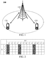
- FIG. 1 exemplarily illustrates one network device and two terminal devices.
- the communication system 100 may include multiple network devices, and other numbers of terminal devices may be included within the coverage range of each network device, which are not limited in the embodiments of the present application.
- the communication system 100 may include other network entities, such as a network controller and a mobile management entity, which are not limited in the embodiments of the present application.
- a device with a communication function in a network/system in the embodiments of the present application may be referred to as a communication device.
- the communication device may include a network device 110 and a terminal device 120 which have communication functions, and the network device 110 and the terminal device 120 may be the specific devices described above, and will not be described repeatedly herein.
- the communication device may also include other devices in the communication system 100, such as network controllers and mobile management entities and other network entities, which are not limited in the embodiments of the present application.
- system and “network” are often used interchangeably in this document.
- the term “and/or” in this document is merely an association relationship describing associated objects, indicating that there may be three relationships, for example, A and/or B may indicate three cases: A alone, A and B, and B alone.
- the symbol “/” in this document generally indicates that objects before and after the symbol "/" have an "or” relationship.
- an NR type II codebook is encoded independently in a frequency domain (each subband). Because spatial quantization accuracy is high, a total feedback amount is too large. By feeding back a frequency domain-space joint codebook, the feedback amount may be greatly reduced under a condition of ensuring NR performance.
- W 1 may be used for indicating 2L spatial beams
- W ⁇ H may be used for indicating a Discrete Fourier Transformation (DFT) base vector of M frequency domains
- ⁇ 2 (a matrix of 2L ⁇ M) may indicates a weighting coefficient of a frequency domain DFT vector pair of arbitrary spatial beam.
- DFT Discrete Fourier Transformation
- Content of Channel state information (CSI) reported by the UE may include L beams indicated by W 1 , M DFT base vectors indicated by W ⁇ H and quantized ⁇ 2 .
- a base station obtains downlink CSI of each layer through a product of the three.
- Main parameters involved in reporting of W 1 , W ⁇ H and ⁇ 2 may include: L value, i.e. a number of space basis DFT vectors; M value (related to a reported frequency domain bandwidth), i.e. a number of reported frequency basis DFT vectors; K0 value, which is used for constraining a maximum number of elements reported by ⁇ 2 .
- L value i.e. a number of space basis DFT vectors
- M value related to a reported frequency domain bandwidth
- K0 value which is used for constraining a maximum number of elements reported by ⁇ 2 .
- a number and/or position of non-zero elements in ⁇ 2 is determined through a bitmap and/or an indication.
- Quantization accuracy in ⁇ 2 is determined by one or more groups of parameters (amplitude and phase). For example, the amplitude may be quantized by 3/4bit, and the phase may also be quantized by 3/4bit.
- the amplitude is quantized by 4 bits and the phase is quantized by 3 bits.
- the amplitude may be quantized with 2 bits and the phase may be quantized with 2 bits.
- both the amplitude and phase are quantized with 4 bits. While for weighting coefficients corresponding to other frequency bases, both the amplitude and phase are quantized with 3 bits.
- M value is a number of columns of ⁇ 2 .
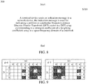
- M frequency bases are selected by the UE from DFT vectors of N3 columns. For example, as shown in FIG. 2 , [0 4 9] is selected from 13 columns.
- a cyclic shift of Inverse Discrete Fourier Transform (IDFT) /DFT performing DFT on a sequence after cyclic shifting is equal to performing DFT on the non-shifted sequence and then multiplying by a linear phase.
- IDFT Inverse Discrete Fourier Transform
- the DFT result only is multiplying the frequency domain by the linear phase, and the amplitude is unchanged.
- Number of shift register Cycle for a binary sequence with a length n, there are a 1 and n-a 0.
- the two sequences are considered to be equivalent, and may be divided into 1 n ⁇ d
- a factor d of gcd (a, n-a) is times of repetitions of subsequences appeared, and d
- n and a are coprime, 1 n ⁇ d
- ged a , n ⁇ a ⁇ d n / d a / d n a / n . That is, there are n different sequences that satisfy cyclic shifting in each set.
- FIG. 4 shows a schematic diagram of a codebook feedback method 200 according to an embodiment of the present application. As shown in FIG. 4 , the method 200 may be executed by a terminal device, and the method 200 includes some or all of the following contents:
- a sequence corresponding to the indication of the M frequency domain DFT vectors is different from a sequence corresponding to the first frequency domain DFT vector indication, and the sequence corresponding to the indication of the M frequency domain DFT vectors has a cyclic shift relationship with the sequence corresponding to the first frequency domain DFT vector indication;
- the first frequency domain DFT vector indication set includes multiple frequency domain DFT vector indication, wherein sequences corresponding to any two frequency domain DFT vector indications in the multiple frequency domain DFT vector indications have a cyclic shift relationship, and the first frequency domain DFT vector indication set comprises the indication of the M frequency domain DFT vectors.
- frequency domain DFT vector indications in any two frequency domain DFT vector indication sets of the multiple frequency domain DFT vector indication sets are not equivalent, and a number of the multiple frequency domain DFT vector indication sets is determined by 1 N 3 ⁇ d
- a sequence value of the sequence corresponding to the first frequency domain DFT vector indication is a minimum value or a maximum value of sequences corresponding to N3 frequency domain DFT vector indications of N3 cyclic shifting operations performed on a sequence corresponding to the indication of the M frequency domain DFT vectors, wherein N3 is the number of columns of the DFT array.
- the method further includes: determining the indication message according to the sequence corresponding to the first frequency domain DFT vector indication, the sequence corresponding to the first frequency domain DFT vector indication has a corresponding relationship with a value of the indication message.
- bit width of the indication message is log2 1 N 3 ⁇ d
- each bit in the indication message is used for indicating any bit in a sequence corresponding to the first frequency domain DFT vector indication except a default bit.
- the base station After receiving the group number, the base station may recover a downlink channel.
- x d 1 e ⁇ j 2 ⁇ d N ⁇ e ⁇ j 2 ⁇ N ⁇ 1 d N is a DFT vector and d is used for indicating cyclic shift of a frequency domain.
- gcd a , n ⁇ a ⁇ d n / d a / d 10 groups at the same time.
- Codebooks in each group have a cyclic shift relationship. Each case is represented by binary number (a highest bit corresponds to No.0 basis) (1 indicates that there is a selection frequency basis at a position thereof). Codebooks with an equivalent relationship within each group are shown in Table 1.
- the message may be encoded through ⁇ log2( nchoosek ( N 3-x, M -y)) ⁇ , and the base station may recover the message by filling 1 in a low bit after recovering the middle bits.
- Embodiment three (ignoring codebooks with a period less than N3):
- group 7 is repeated twice in the unit of 4 bits ⁇ 0011, 0110, 1001, 1100 ⁇
- group 9 is repeated four times in the unit of 2 bits ⁇ 01, 10 ⁇ .
- the network ignores codebooks of group 7 and group 9, that is, group numbers allowed to be reported by UE are shown in Table 3.
- Table 3 Group number Select M in N3 0 '00001111' '00011110' '00111100' '01111000' '10000111' '11000011' '11100001' '11110000' 1 '00010111' '00101110' '01011100' '01110001' '10001011' '10111000' '11000101' '11100010' 2 '00011011' '00110110' '01100011' '01101100' '10001101' '10110001' '11000110' '11011000' 3 '00011101' '00111010' '01000111' '01110100' '10001110' '10100011' '11010001' '11101000' 4 '00100111' '00111001
- N3 and M are mutually prime.
- a factor of GCD (N3, M) is only [1], and there is no repetition of sequences smaller than N3.
- the codebook may be completely divided into N3 groups to achieve best compression efficiency, as shown in Table 4.
- Table 4 Group number Select M from N3 0 0000001111111' 0000011111110' '0000111111100' '0001111111000' '0011111110000' '1111111000000' 1 '0000101111110' '0001011111100' '0010111111000' '0101111110000' '1111110000010' ... .
- the network side defines a candidate set of UE in a predefined way, as shown in Table 5.
- Table 5 Group number Sequence Group number Sequence Group number Sequence Group number Sequence Group number Sequence Group number Sequence Group number Sequence Group number Sequence 0 '1111111000000' 24 '1111011010000' 48 '1111100100010' 72 '1110110101000' 96 '1110010100110' 120 '1101011001100' 1 '1111110000010' 25 '1111100110000' 49 '1111100011000' 73 '1110111001000' 97 '1110110010100' 121 '1101101001100' 2 '11111000000110' 26 '1111101010000' 50 '1111000110010' 74 '1111001011000' 98 '1111010010100' 122 '1110101001100' 3 '1111000001110' 27 '1111110010000' 51 '1110001100110' 75 '111100
- Sequence mapping (from a high bit to a low bit) corresponds to DFT [0, 2pi], as shown in FIG. 6 .
- Sequence mapping (from a high bit to a low bit) corresponds to DFT from a low frequency to a high frequency, as shown in FIG. 7 .
- the network may guarantee higher feedback accuracy of CSI at a low frequency with mode 1 or mode 2.
- the UE selects a best codebook from a restricted set (in the embodiment, a selection is from 132 codebooks. If there is no restriction, there are 1716 candidate codebooks), and feeds back to the base station.
- FIG. 8 shows a schematic block diagram of a codebook feedback method 300 according to an embodiment of the present application.
- the method 300 may be executed by a terminal device, and the method 300 includes some or all of the following contents: S310, the terminal device sends an indication message to a network device, wherein the indication message is used for indicating a position in a particular frequency domain Discrete Fourier Transform (DFT) vector in a DFT array corresponding to a strongest coefficient of a weighting coefficient array in a space-frequency domain of a codebook.
- DFT Discrete Fourier Transform
- bit width of the indication message is log2(2 ⁇ L ), herein 2 ⁇ L is a number of rows in a space-frequency domain matrix.
- the method of claim 1 is characterized in that the bit width of the indication message is ⁇ log2(L nz ) ⁇ , herein Lnz is a number of rows occupied by non-zero coefficients in the space-frequency domain matrix.
- the method further includes that the terminal device performs a cyclic shift operation on frequency domain DFT vectors corresponding to the non-zero coefficient in the space-frequency domain matrix such that the strongest coefficient corresponds to a particular frequency domain DFT vector in the DFT array.
- the particular frequency domain DFT vector is the first frequency domain DFT vector or a last frequency domain DFT vector in the DFT array.
- Lnz represents a number of space bases corresponding to non-zero elements only in space.
- the efficiency of indicating the strongest coefficient is enhanced.
- the conventional scheme is on the left.
- a selection of M DFT vectors [3 4 5 6 7] is cyclic shifted to [0 1 2 6 7], and then only 2 bits (within a 0th DFT vector) are needed to indicate a number of rows of the strongest coefficient (log2(2L)).
- a scheme of FIG. 10 may be adopted.
- the UE indicates the strongest coefficient, it may be found that there are non-zero coefficients on rows [0 1 4 5]. So that the strongest coefficient is on a fourth space basis may be indicated by 4 bits [0010].
- FIG. 11 shows a schematic block diagram of a codebook feedback method 400 according to an embodiment of the present application. As shown in FIG. 11 , the method 400 may be executed by a terminal device, and the method 400 includes some or all of the following contents:
- the first frequency domain DFT vector indication set does not include a second frequency domain DFT vector indication, wherein a sequence corresponding to the second frequency domain DFT vector indication has a cyclic shift relationship with a sequence corresponding to the first frequency domain DFT vector indication.
- the first frequency domain DFT vector indication set includes multiple frequency domain DFT vector indications, and sequences corresponding to any two frequency domain DFT vector indications in the multiple frequency domain DFT vector indications have a cyclic shift relationship.
- FIG. 12 shows a schematic block diagram of a codebook feedback method 500 according to an embodiment of the present application.
- the method 500 may be executed by a terminal device, and the method 500 includes some or all of the following contents: S510, a network device receives an indication message sent by a terminal device, wherein the indication message is used for indicating a position in a particular frequency domain Discrete Fourier Transform (DFT) vector in a DFT array corresponding to a strongest coefficient of a weighting coefficient array in a space-frequency domain of a codebook.
- DFT Discrete Fourier Transform
- sequence numbers of the foregoing processes do not mean execution sequences in various embodiments of the present application.
- the execution sequences of the processes should be determined according to functions and internal logic of the processes, and should not constitute any limitation on the implementation processes of the embodiments of the present application.
- FIG. 13 shows a schematic block diagram of a terminal device 600 according to an embodiment of the present application.
- the terminal device 600 includes:
- terminal device 600 may correspond to the terminal device in the method embodiment of the present application, and the above-mentioned and other operations and/or functions of various units in the terminal device 600 are respectively for implementing the corresponding processes of the terminal device in the method shown in FIG. 4 , which are not repeated here for brevity.
- FIG. 14 shows a schematic block diagram of a terminal device 700 according to an embodiment of the present application.
- the terminal device 700 includes: a communication unit 710, configured to send an indication message to a network device, wherein the indication message is used for indicating a position in a particular frequency domain Discrete Fourier Transform (DFT) vector in a DFT array corresponding to a strongest coefficient of a weighting coefficient array in a space-frequency domain of a codebook.
- DFT Discrete Fourier Transform
- terminal device 700 may correspond to the terminal device in the method embodiment of the present application, and the above-mentioned and other operations and/or functions of various units in the terminal device 700 are respectively for implementing the corresponding processes of the terminal device in the method shown in FIG. 8 , which are not repeated here for brevity.
- FIG. 15 is a schematic block diagram of a network device 800 according to an embodiment of the present application. As shown in FIG. 15 , the network device 800 includes:
- the network device 800 may correspond to the network device in the method embodiments of the present application, and the above-mentioned and other operations and/or functions of various units in the device 800 are respectively for implementing the corresponding processes of the network device in the method shown in FIG. 11 , which are not repeated here for the sake of brevity.
- FIG.16 is a schematic block diagram of a network device 900 according to an embodiment of the present application.
- the network device 900 includes: a communication unit 910, configured to receive an indication message sent by a terminal device, wherein the indication message is used for indicating a position in a particular frequency domain Discrete Fourier Transform (DFT) vector in a DFT array corresponding to a strongest coefficient of a weighting coefficient array in a space-frequency domain of a codebook.
- DFT Discrete Fourier Transform
- the network device 900 may correspond to the network device in the method embodiments of the present application, and the above-mentioned and other operations and/or functions of various units in the device 900 are respectively for implementing the corresponding processes of the network device in the method shown in FIG. 12 , which are not repeated here for the sake of brevity.
- the processor in the embodiments of the present application may be an integrated circuit chip having a signal processing capability.
- the steps of the foregoing method embodiments may be implemented through an integrated logic circuit of hardware in the processor or instructions in a form of software.
- the processor described above may be a general purpose processor, a digital signal processor (DSP), an application specific integrated circuit (ASIC), a field programmable gate array (FPGA) or other programmable logic device, a discrete gate or a transistor logic device, or a discrete hardware component.
- the processor may implement or perform various methods, steps and logical block diagrams disclosed in the embodiments of the present application.
- the general purpose processor may be a microprocessor, or the processor may also be any conventional processor, or the like.
- the steps of the methods disclosed in combination with the embodiments of the present application may be directly embodied to be implemented by a hardware decoding processor, or may be implemented by a combination of hardware and software modules in the decoding processor.
- the software modules may be located in a storage medium which is mature in the art, such as a random access memory, a flash memory, a read-only memory, a programmable read-only memory, an electrically erasable programmable memory, or a register.
- the storage medium is located in the memory, and the processor reads information in the memory and performs the steps of the foregoing methods in combination with its hardware.
- the memory in the embodiments of the present application may be a volatile memory or a non-volatile memory, or may include both a volatile memory and a non-volatile memory.
- the non-volatile memory may be a read-only memory (ROM), a programmable read-only memory (PROM), an erasable programmable read-only memory (EPROM), an electrically erasable programmable read-only memory (EEPROM), or a flash memory.
- the volatile memory may be a random access memory (RAM), which is used as an external cache.
- RAMs may be available, such as a static random access memory (SRAM), a dynamic random access memory (DRAM), a synchronous dynamic random access memory (SDRAM), a double data rate synchronous dynamic random access memory (DDR SDRAM), an enhanced synchronous dynamic random access memory (ESDRAM), a synchronous link dynamic random access memory (SLDRAM), and a direct Rambus dynamic random access memory (DR RAM).
- SRAM static random access memory
- DRAM dynamic random access memory
- SDRAM synchronous dynamic random access memory
- DDR SDRAM double data rate synchronous dynamic random access memory
- ESDRAM enhanced synchronous dynamic random access memory
- SLDRAM synchronous link dynamic random access memory
- DR RAM direct Rambus dynamic random access memory
- the memory in the embodiments of the present application may also be a Static RAM (SRAM), a Dynamic RAM (DRAM), a Synchronous DRAM (SDRAM), a Double Data Rate SDRAM (DDR SDRAM), an Enhanced SDRAM (ESDRAM), a Synchlink DRAM (SLDRAM), a direct Rambus RAM (DR RAM), or the like. That is, the memory in the embodiments of the present application is intended to include, but not be limited to, these and any other suitable types of memories.
- SRAM Static RAM
- DRAM Dynamic RAM
- SDRAM Synchronous DRAM
- DDR SDRAM Double Data Rate SDRAM
- ESDRAM Enhanced SDRAM
- SLDRAM Synchlink DRAM
- DR RAM direct Rambus RAM
- An embodiment of the present application further provides a computer readable storage medium configured to store a computer program.
- the computer readable storage medium may be applied in a network device of the embodiments of the present application, and when the computer program is run on a computer, the computer is enabled to perform the corresponding processes implemented by the network device in various methods of the embodiments of the present application, which are not repeated here for brevity.
- the computer readable storage medium may be applied in a terminal device of the embodiments of the present application, and when the computer program is run on a computer, the computer is enabled to perform the corresponding processes implemented by a mobile terminal/terminal device in various methods of embodiments of the present application, which are not repeated here for brevity.
- An embodiment of the present application further provides a computer program product including computer program instructions.
- the computer program product may be applied in a network device of the embodiments of the present application, and when the computer program instructions are executed by a computer, the computer is enabled to perform the corresponding processes implemented by the network device in various methods of the embodiments of the present application, which are not repeated here for brevity.
- the computer program product may be applied in a terminal device of embodiments of the present application, and when the computer program instructions are executed by a computer, the computer is enabled to perform corresponding processes implemented by the mobile terminal/terminal device in various methods of embodiments of the present application, which are not repeated here for brevity.
- An embodiment of the present application further provides a computer program.
- the computer program may be applied in a network device of the embodiments of the present application.
- the computer program When the computer program is run on a computer, the computer is enabled to perform the corresponding processes implemented by the network device in various methods of the embodiments of the present application, which are not repeated here for brevity.
- the computer program may be applied in a terminal device of embodiments of the present application.
- the computer program When the computer program is run on a computer, the computer is enabled to perform corresponding processes implemented by the terminal device in various methods of embodiments of the present application, which are not repeated here for brevity.
- the disclosed systems, devices and methods may be implemented in other ways.
- the device embodiments described above are only illustrative, for example, the division of the units is only a logical function division, and there may be other division modes in actual implementation.
- multiple units or components may be combined or integrated into another system, or some features may be ignored or not executed.
- the displayed or discussed coupling or direct coupling or communication connection between each other may be an indirect coupling or communication connection through some interfaces, devices or units, which may be in electrical, mechanical or other forms.
- the unit described as a separate component may or may not be physically separated, and the component shown as a unit may or may not be a physical unit, i.e., it may be located in one place or may be distributed across multiple network units. Part or all of the units may be selected according to actual needs to achieve the purpose of the embodiments.
- various functional units in various embodiments of the present application may be integrated into one processing unit, or may exist physically separately, or two or more than two units may be integrated into one unit.
- the software functional units may be stored in a computer readable storage medium.
- the computer software product is stored in a storage medium, and includes several instructions for instructing a computer device (which may be a personal computer, a server, or a network device, etc.) to perform all or part of the steps of various embodiments of the present application.
- the aforementioned storage medium may include any medium that can store program codes, such as a USB flash disk, a mobile hard disk, a read-only memory (ROM), a random access memory (RAM), a magnetic disk, or an optical disk.
Landscapes
- Engineering & Computer Science (AREA)
- Computer Networks & Wireless Communication (AREA)
- Signal Processing (AREA)
- Physics & Mathematics (AREA)
- Mathematical Physics (AREA)
- Discrete Mathematics (AREA)
- General Physics & Mathematics (AREA)
- Mobile Radio Communication Systems (AREA)
Abstract
Description
- Embodiments of the present application relate to the field of communication, and particularly to a codebook feedback method, a terminal device, and a network device.
- In R16, a New Radio (NR) type II codebook may be expressed as


- Content of Channel State Information (CSI) reported by a terminal device to a network device includes L beams of W 1, M frequency domain DFT vectors indicated by

- At present, the terminal device indicates positions of M frequency domain DFT vectors by means of ┌log2(nchoosek(N3,M))┐, in which N3 indicates a number of columns of

- Embodiments of the present application provide a codebook feedback method, a terminal device and a network device, which are beneficial to reducing signaling overhead when the terminal device feeds back a codebook.
- In a first aspect, a codebook feedback method is provided, which includes: selecting, by a terminal device, M frequency domain Discrete Fourier Transform (DFT) vectors from a DFT array; determining, by the terminal device, a first frequency domain DFT vector indication set from multiple frequency domain DFT vector indication sets according to an indication of the M frequency domain DFT vectors, wherein the indication of the M frequency domain DFT vectors is equivalent to a first frequency domain DFT vector indication in the first frequency domain DFT vector indication set, and M is a positive integer; and sending, by the terminal device, an indication message to the network device, wherein the indication message is used for indicating the first frequency domain DFT vector indication set.
- In a second aspect, a codebook feedback method is provided, which includes: sending, by a terminal device, an indication message to a network device, wherein the indication message is used for indicating a position in a particular frequency domain Discrete Fourier Transform (DFT) vector in a DFT array corresponding to a strongest coefficient of a weighting coefficient array of a space-frequency domain of a codebook.
- In a third aspect, a codebook feedback method is provided, which includes: receiving, by a network device, indication information sent by a terminal device, wherein the indication information is used for indicating a first frequency domain Discrete Fourier Transform (DFT) vector indication set in multiple frequency domain DFT vector indication sets; and recovering, by the network device, a downlink channel according to any one frequency domain DFT vector indication equivalent to a first frequency domain DFT vector indication in the first frequency domain DFT vector indication set.
- In a fourth aspect, a codebook feedback method is provided, which includes: receiving, by a network device, an indication message sent by a terminal device, wherein the indication message is used for indicating a position in a particular frequency domain Discrete Fourier Transform (DFT) vector in a DFT array corresponding to a strongest coefficient of a weighting coefficient array in a space-frequency domain of a codebook.
- In a fifth aspect, a terminal device is provided, which is configured to perform the method in the first aspect described above or various implementations thereof.
- Specifically, the terminal device includes function modules used for performing the method in the first aspect described above or various implementations thereof.
- In a sixth aspect, a terminal device is provided, which is configured to perform the method in the second aspect or various implementations thereof.
- Specifically, the terminal device includes function modules for performing the method in the above second aspect or various implementations thereof.
- In a seventh aspect, a network device is provided, which is configured to perform the method in the third aspect described above or various implementations thereof.
- Specifically, the network device includes function modules used for performing the method in the third aspect described above or various implementations thereof.
- In an eighth aspect, a network device is provided, which is configured to perform the method in the fourth aspect described above or various implementations thereof.
- Specifically, the network device includes function modules used for performing the method in the fourth aspect described above and various implementations thereof.
- In a ninth aspect, a network device is provided, which includes a processor and a memory. The memory is configured to store a computer program, and the processor is configured to call and run the computer program stored in the memory to perform the method in the first aspect to the second aspect described above or various implementation modes thereof.
- In a tenth aspect, a network device is provided, which includes a processor and a memory. The memory is configured to store a computer program, and the processor is configured to call and run the computer program stored in the memory to perform the method in the third aspect to the fourth aspect described above and various implementations thereof.
- In an eleventh aspect, a chip is provided, which is configured to implement the method in any one of the first aspect to the fourth aspect or various implementations thereof.
- Specifically, the chip includes a processor configured to call and run a computer program from a memory, enabling a device in which the chip is installed to perform the method in any one of the first aspect to the fourth aspect or various implementations thereof.
- In a twelfth aspect, a computer-readable storage medium is provided, which is configured to store a computer program, wherein when the computer program is run on a computer, the computer is enabled to perform the method in any one of the first aspect to the fourth aspect or various implementations thereof.
- In a thirteenth aspect, a computer program product is provided, which includes computer program instructions, when the computer program instructions are executed by a computer, the computer is enabled to perform the method in any one of the first aspect to the fourth aspect or various implementations thereof.
- In a fourteenth aspect, a computer program is provided. when the computer program is run on a computer, the computer is enabled to perform the method in any one of the above first aspect to the second aspect or various implementations thereof.
-
-
FIG. 1 is a schematic diagram of an architecture of a communication system according to an embodiment of the present application. -
FIG. 2 shows a schematic diagram for indicating selected M frequency domain DFT vectors. -
FIG. 3 shows a schematic diagram of M frequency domain DFT vectors that are cyclically shifted. -
FIG. 4 is a schematic diagram of a codebook feedback method according to an embodiment of the present application. -
FIG. 5 shows another schematic diagram for indicating selected M frequency domain DFT vectors. -
FIG. 6 shows a mapping diagram between DFT vectors and codebook restriction types. -
FIG. 7 shows a mapping diagram among DFT vectors, frequencies and codebook restriction types. -
FIG. 8 is another schematic diagram of a codebook feedback method according to an embodiment of the present application. -
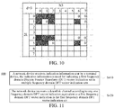
FIG. 9 is a schematic diagram of a DFT vector position corresponding to a strongest coefficient according to an embodiment of the present application. -
FIG. 10 is another schematic diagram of a DFT vector position corresponding to a strongest coefficient according to an embodiment of the present application. -
FIG. 11 is another schematic diagram of a codebook feedback method according to an embodiment of the present application. -
FIG. 12 is another schematic diagram of a codebook feedback method according to an embodiment of the present application. -
FIG. 13 is a schematic block diagram of a terminal device according to an embodiment of the present application. -
FIG. 14 is a schematic block diagram of a terminal device according to an embodiment of the present application. -
FIG. 15 is a schematic block diagram of a network device according to an embodiment of the present application. -
FIG. 16 is a schematic block diagram of a network device according to an embodiment of the present application. - Technical solutions in embodiments of the present application will be described below with reference to drawings in the embodiments of the present application. It is apparent that the embodiments described are just some of the embodiments of the present application, but not all of the embodiments of the present application. Based on the embodiments of the present application, all other embodiments achieved by a person of ordinary skill in the art without paying inventive efforts are within the protection scope of the present application.
- It should be understood that the technical solutions of the embodiments of the present application may be applied to various communication systems, such as, a Global System of Mobile communication (GSM) system, a Code Division Multiple Access (CDMA) system, a Wideband Code Division Multiple Access (WCDMA) system, a General Packet Radio Service (GPRS) system, a Long Term Evolution (LTE) system, a LTE Frequency Division Duplex (FDD) system, a LTE Time Division Duplex (TDD) system, a Universal Mobile Telecommunication System (UMTS) system, a Worldwide Interoperability for Microwave Access (WiMAX) communication system, a New Radio (NR) or future 5G System.
- In particular, the technical solutions of the embodiments of the present application can be applied to various communication systems based on non-orthogonal multiple access technologies, such as a Sparse Code Multiple Access (SCMA) system, and a Low Density Signature (LDS) system, etc. Of course, the SCMA system and the LDS system may also be referred to as other names in the communication field. Further, the technical solutions of the embodiments of the present application can be applied to a multicarrier transmission system employing non-orthogonal multiple access technology, such as an Orthogonal Frequency Division Multiplexing (OFDM) system based on the non-orthogonal multiple access technology, a Filter Bank Multi-Carrier (FBMC) system, a Generalized Frequency Division Multiplexing (GFDM) system, and a Filtered OFDM (F-OFDM) system, etc.
- Illustratively, a
communication system 100 to which an embodiment of the present application is applied is shown inFIG. 1 . Thecommunication system 100 may include anetwork device 110. Thenetwork device 110 may be a device that communicates with terminal devices 120 (or referred to as communication terminals, or terminals). Thenetwork device 110 may provide communication coverage for a specific geographical area, and may communicate with terminal devices located within the coverage area. Optionally, thenetwork device 110 may be a Base Transceiver Station (BTS) in a GSM system or CDMA system, or a NodeB (NB) in a WCDMA system, or an Evolutional Node B (eNB or eNodeB) in an LTE system, or a radio controller in a Cloud Radio Access Network (CRAN), or the network device may be a mobile switching center, a relay station, an access point, a vehicle-mounted device, a wearable device, a hub, a switch, a bridge, a router, a network device gNB in a 5G network, or a network device in a future evolved Public Land Mobile Network (PLMN), etc. - The
wireless communication system 100 further includes at least oneterminal 120 located within the coverage range of thenetwork device 110. The terminal device may be a User Equipment (UE), an access terminal, a user unit, a user station, a mobile site, a mobile station, a remote station, a remote terminal, a mobile device, a user terminal, a terminal, a wireless communications device, a user agent, or a user apparatus. The access terminal may be a cellular phone, a cordless phone, a session initiation protocol (SIP) phone, a wireless local loop (WLL) station, a personal digital assistant (PDA), a handheld device with a wireless communication function, a computing device or other processing device connected to a wireless modem, an on-board device, a wearable device, a terminal device in a future 5G network, or a terminal device in a future evolved Public Land Mobile Network (PLMN), etc., which is not restricted in embodiments of the present invention. - Optionally, a device to device (D2D) communication may be performed between the
terminal devices 120. - Optionally, the 5G system or 5G network may be referred to as a New Radio (NR) system or a NR network.
-
FIG. 1 exemplarily illustrates one network device and two terminal devices. Optionally, thecommunication system 100 may include multiple network devices, and other numbers of terminal devices may be included within the coverage range of each network device, which are not limited in the embodiments of the present application. - Optionally, the
communication system 100 may include other network entities, such as a network controller and a mobile management entity, which are not limited in the embodiments of the present application. - It should be understood that a device with a communication function in a network/system in the embodiments of the present application may be referred to as a communication device. Taking the
communication system 100 shown inFIG. 1 as an example, the communication device may include anetwork device 110 and aterminal device 120 which have communication functions, and thenetwork device 110 and theterminal device 120 may be the specific devices described above, and will not be described repeatedly herein. The communication device may also include other devices in thecommunication system 100, such as network controllers and mobile management entities and other network entities, which are not limited in the embodiments of the present application. - It should be understood that the terms "system" and "network" are often used interchangeably in this document. The term "and/or" in this document is merely an association relationship describing associated objects, indicating that there may be three relationships, for example, A and/or B may indicate three cases: A alone, A and B, and B alone. In addition, the symbol "/" in this document generally indicates that objects before and after the symbol "/" have an "or" relationship.
- For each layer codebook of a multi-layer codebook, an NR type II codebook is encoded independently in a frequency domain (each subband). Because spatial quantization accuracy is high, a total feedback amount is too large. By feeding back a frequency domain-space joint codebook, the feedback amount may be greatly reduced under a condition of ensuring NR performance. Particularly, an R16 NR type II codebook may be expressed as a following formula (1):

- Herein, W1 may be used for indicating 2L spatial beams;

- Content of Channel state information (CSI) reported by the UE may include L beams indicated by W 1, M DFT base vectors indicated by

- Main parameters involved in reporting of W 1,

- Herein, M value is a number of columns of Ŵ 2. M frequency bases are selected by the UE from DFT vectors of N3 columns. For example, as shown in
FIG. 2 , [0 4 9] is selected from 13 columns. - A cyclic shift of Inverse Discrete Fourier Transform (IDFT) /DFT: performing DFT on a sequence after cyclic shifting is equal to performing DFT on the non-shifted sequence and then multiplying by a linear phase.
- If X k, = DFT ({x}n) k
- X is cyclic shifted d, the DFT result is

- That is, the DFT result only is multiplying the frequency domain by the linear phase, and the amplitude is unchanged.
- If the same cyclic shift is used for each row of W2 (a Type II codebook is selected by column), a phase is multiplied when a channel is recovered at the base station end, but there is no effect to a MIMO channel.
- Under this condition, it may be considered that two codewords are equivalent when M columns selected by the two codewords belong to a cyclic shift relationship.
- As shown in
FIG. 3 , when the cyclic shift (right shift) d=0/1/3/4, if a codeword is X k for d=0, then the rest codewords are
- Number of shift register Cycle: for a binary sequence with a length n, there are a 1 and
n-a 0. When two sequences belong to a cyclic shift, the two sequences are considered to be equivalent, and may be divided into
- Herein, a factor d of gcd (a, n-a) is times of repetitions of subsequences appeared, and d|n indicates that d is a factor of n; gcd is to find a greatest common divisor, ϕ is Euler function, and ( ) indicates to find combinatorial number. Particularly, when n and a are coprime,

-
FIG. 4 shows a schematic diagram of acodebook feedback method 200 according to an embodiment of the present application. As shown inFIG. 4 , themethod 200 may be executed by a terminal device, and themethod 200 includes some or all of the following contents: - S210, the terminal device selects M frequency domain Discrete Fourier Transform (DFT) vectors from a DFT array;
- S220, the terminal device determines a first frequency domain DFT vector indication set from multiple frequency domain DFT vector indication sets according to an indication of the M frequency domain DFT vectors, wherein the indication of the M frequency domain DFT vectors is equivalent to a first frequency domain DFT vector indication in the first frequency domain DFT vector indication set, and M is a positive integer; and
- S230, the terminal device sends an indication message to a network device, wherein the indication message is used for indicating the first frequency domain DFT vector indication set.
- Optionally, a sequence corresponding to the indication of the M frequency domain DFT vectors is different from a sequence corresponding to the first frequency domain DFT vector indication, and the sequence corresponding to the indication of the M frequency domain DFT vectors has a cyclic shift relationship with the sequence corresponding to the first frequency domain DFT vector indication; or
- The first frequency domain DFT vector indication set includes multiple frequency domain DFT vector indication, wherein sequences corresponding to any two frequency domain DFT vector indications in the multiple frequency domain DFT vector indications have a cyclic shift relationship, and the first frequency domain DFT vector indication set comprises the indication of the M frequency domain DFT vectors.
- Optionally, frequency domain DFT vector indications in any two frequency domain DFT vector indication sets of the multiple frequency domain DFT vector indication sets are not equivalent, and a number of the multiple frequency domain DFT vector indication sets is determined by

- Optionally, a sequence value of the sequence corresponding to the first frequency domain DFT vector indication is a minimum value or a maximum value of sequences corresponding to N3 frequency domain DFT vector indications of N3 cyclic shifting operations performed on a sequence corresponding to the indication of the M frequency domain DFT vectors, wherein N3 is the number of columns of the DFT array.
- Optionally, the method further includes: determining the indication message according to the sequence corresponding to the first frequency domain DFT vector indication, the sequence corresponding to the first frequency domain DFT vector indication has a corresponding relationship with a value of the indication message.
- Optionally, bit width of the indication message is

- Optionally, each bit in the indication message is used for indicating any bit in a sequence corresponding to the first frequency domain DFT vector indication except a default bit.
- Particularly,
- 1. Selection cases of M columns are divided into several groups, and each group contains at most N3 cases, which satisfy a relationship that every two cases are cyclic shifts of each other;
- A relationship of cyclic shift of binary sequence means that one sequence may be obtained by left (right) cyclic shifting of another sequence.
▪ x0 = 00001111, x1 = 00011110, ..., x7 = 10000111 belong to a cyclic shift relationship. - May be divided into

- A relationship of cyclic shift of binary sequence means that one sequence may be obtained by left (right) cyclic shifting of another sequence.
- 2. After selecting M columns, a UE finds a group reported by the UE and reports an indication, a network may know a group number at which the group is located through the indication.
- a) As there are multiple sequences in each group, the UE may find its corresponding group through cyclic shift.
- i. performing cyclic shifting n times on a sequence selected by UE, and taking a minimum value of the sequences.
- ii, through an indication message whose bit width is

- iii. It may be indicated by a message whose bit width is a combinatorial number of ┌log2(nchoosek(N3-x,M-y))┐. What is corresponded here is information except a highest bit and a lowest bit. The base station determines a final value by combining default values of the highest bit and lowest bit.
- a) As there are multiple sequences in each group, the UE may find its corresponding group through cyclic shift.
- After receiving the group number, the base station may recover a downlink channel.
- An existing Type II codebook is further decomposed. Considering influence of cyclic shift, the codebook may be decomposed into

- Herein,

- N3=8, M=4, then there are 70 kinds of selection cases in total, which may be divided into

Table 1 Group number Select M in N3 0 '00001111' '00011110' '00111100' '01111000' '10000111' '11000011' '11100001' '11110000' 1 '00010111' '00101110' '01011100' '01110001' '10001011' 110111000' '11000101' '11100010' 2 '00011011' '00110110' '01100011' '01101100' '10001101' '10110001' '11000110' '11011000' 3 '00011101' '00111010' '01000111' '01110100' '10001110' '10100011' '11010001' '11101000' 4 '00100111' '00111001' '01001110' '01110010' '10010011' '10011100' '11001001' '11100100' 5 '00101011' '01010110' '01011001' '01100101' '10010101' '10101100' '10110010' '11001010' 6 '00101101' '01001011' '01011010' '01101001' '10010110' '10100101' '10110100' '11010010' 7 '00110011' '01100110' '10011001' '11001100' 8 '00110101' '01001101' '01010011' '01101010' '10011010' '10100110' '10101001' '11010100' 9 '01010101' '10101010' - When UE selects M columns, columns [3 5 6 7] are selected, as shown in
Figure 5 . Then, when reporting, it is a third group that is found according to [00010111] (it may be indexed by a minimum value corresponding to a leading code word (00011101)), and a reporting indication is 3 (because the base station can recover a channel with any one in a third row). This embodiment indicates a selection of DFT vectors using a bitmap for convenience of the description. However, if an implementation mode of combinatorial number is adopted, the operation process is consistent, indicating a binary sequence to correspond to the combinatorial number. - Considering computational complexity of calculating a corresponding relationship between a reporting indication and a group number, after 00011101 is obtained, only middle 6 bits may be encoded (the highest bit must be 0, and the lowest bit must be 1). That is, the message may be encoded through ┌log2(nchoosek(N3-x,M -y))┐, and the base station may recover the message by filling 1 in a low bit after recovering the middle bits.
- Embodiment three (ignoring codebooks with a period less than N3):
- For N3=8, M=4, because GCD (N3,M) =[1 2 4], there is a repetition of sequences in a unit of 2 and a unit of 4 (i.e.,
group 7 and group 9), as shown in Table 2.Table 2 Group number Select M in N3 0 '00001111' '00011110' '00111100' '01111000' '10000111' '11000011' '11100001' '11110000' 1 '00010111' '00101110' '01011100' '01110001' '10001011' '10111000' '11000101' '11100010' 2 '00011011' '00110110' '01100011' '01101100' '10001101' '10110001' '11000110' '11011000' 3 '00011101' '00111010' '01000111' '01110100' '10001110' '10100011' '11010001' '11101000' 4 '00100111' '00111001' '01001110' '01110010' '10010011' '10011100' '11001001' '11100100' 5 '00101011' '01010110' '01011001' '01100101' '10010101' '10101100' '10110010' '11001010' 6 '00101101' '01001011' '01011010' '01101001' '10010110' '10100101' '10110100' '11010010' 7 '00110011' '01100110' '10011001' '11001100' 8 '00110101' '01001101' '01010011' '01101010' '10011010' '10100110' '10101001' '11010100' 9 '01010101' 110101010, - Herein,
group 7 is repeated twice in the unit of 4 bits {0011, 0110, 1001, 1100},group 9 is repeated four times in the unit of 2 bits {01, 10}. - In order to simplify implementation complexity, the network ignores codebooks of
group 7 andgroup 9, that is, group numbers allowed to be reported by UE are shown in Table 3.Table 3 Group number Select M in N3 0 '00001111' '00011110' '00111100' '01111000' '10000111' '11000011' '11100001' '11110000' 1 '00010111' '00101110' '01011100' '01110001' '10001011' '10111000' '11000101' '11100010' 2 '00011011' '00110110' '01100011' '01101100' '10001101' '10110001' '11000110' '11011000' 3 '00011101' '00111010' '01000111' '01110100' '10001110' '10100011' '11010001' '11101000' 4 '00100111' '00111001' '01001110' '01110010' '10010011' '10011100' '11001001' '11100100' 5 '00101011' '01010110' '01011001' '01100101' '10010101' '10101100' '10110010' '11001010' 6 '00101101' '01001011' '01011010' '01101001' '10010110' '10100101' '10110100' '11010010' 7 '00110101' '01101101' '10010011' '01101010' '10011010' '10100110' '10101001' '11010100' - For N3=13 and M=ceil (1/2∗N3) =7, then N3 and M are mutually prime. A factor of GCD (N3, M) is only [1], and there is no repetition of sequences smaller than N3. The codebook may be completely divided into N3 groups to achieve best compression efficiency, as shown in Table 4.
Table 4 Group number Select M from N3 0 0000001111111' 0000011111110' '0000111111100' '0001111111000' '0011111110000' '1111111000000' 1 '0000101111110' '0001011111100' '0010111111000' '0101111110000' '1111110000010' ... ....... 130 '0011101010101' '0100111010101' '0101001110101' '0101010011101' '0101010100111' '1110101010100' 131 '0101010101011' '0101010101101' '0101010110101' '0101011010101' '0101101010101' '1101010101010' - The network side defines a candidate set of UE in a predefined way, as shown in Table 5.
Table 5 Group number Sequence Group number Sequence Group number Sequence Group number Sequence Group number Sequence Group number Sequence 0 '1111111000000' 24 '1111011010000' 48 '1111100100010' 72 '1110110101000' 96 '1110010100110' 120 '1101011001100' 1 '1111110000010' 25 '1111100110000' 49 '1111100011000' 73 '1110111001000' 97 '1110110010100' 121 '1101101001100' 2 '11111000000110' 26 '1111101010000' 50 '1111000110010' 74 '1111001011000' 98 '1111010010100' 122 '1110101001100' 3 '1111000001110' 27 '1111110010000' 51 '1110001100110' 75 '1111001101000' 99 '1111001010100' 123 '1101100110100' 4 '1111011100000' 28 '1111110001000' 52 '1110110001100' 76 '1111010011000' 100 '1110010101010' 124 '1110100110100' 5 '1111101100000' 29 '1111100010010' 53 '1111010001100' 77 '1111010101000' 101 '1101100101010' 125 '1110011010100' 6 '1111110100000' 30 '1111000100110' 54 '1111000110100' 78 '1111011001000' 102 '1110100101010' 126 '1101010101100' 7 '1111110000100' 31 '1110111000100' 55 '1110001101010' 79 '1111100101000' 103 '1110010101100' 127 '1101010110100' 8 '1111100001010' 32 '1111011000100' 56 '1101100011010' 80 '1111101001000' 104 '1101011001010' 128 '1101011010100' 9 '1111000010110' 33 '1111101000100' 57 '1110100011010' 81 '1111100100100' 105 '1101101001010' 129 '1101101010100' 10 '1110111000010' 34 '1111100010100' 58 '1110001101100' 82 '1111001001010' 106 '1110011001010' 130 '1110101010100' 11 '1111011000010' 35 '1111000101010' 59 '1101101011000' 83 '1110010010110' 107 '1110101001010' 131 '1101010101010' 12 '1111101000010' 36 '1110001010110' 60 '1101101101000' 84 '1110110010010' 108 '1110010110010' 13 '1111100001100' 37 '1110110001010' 61 '1110011000110' 85 '1111010010010' 109 '1101100101100' 14 '1111000011010' 38 '1111010001010' 62 '1110101000110' 86 '1111001001100' 110 '1110100101100' 15 '1110000110110' 39 '1111000101100' 63 '1111001000110' 87 '1110010011010' III '1110010110100' 16 '1110110000110' 40 '1110001011010' 64 '1111000111000' 88 '1101101100100' 112 '1101010110010' 17 '1111010000110' 41 '1101101100010' 65 '1110010111000' 89 '1110100100110' 113 '1101011010010' 18 '1111000011100' 42 '1110100010110' 66 '1110011011000' 90 '1110011100100' 114 '1101100110010' 19 '1110101110000' 43 '1110011100010' 67 '1110100011100' 91 1110101100100 115 '1101101010010' 20 '1110110110000' 44 '1110101100010' 68 '1110100111000' 92 '1110110100100' 116 '1110011010010' 21 '1110111010000' 45 '1110110100010' 69 '1110101011000' 93 '1111001100100' 117 '1110100110010' 22 '1111001110000' 46 '1111001100010' 70 '1110101101000' 94 '1111010100100' 118 '1110101010010' 23 '1111010110000' 47 '1111010100010' 71 '1110110011000' 95 '1111001010010' 119 '1110011001100' - Difference from the previous embodiments is that the embodiment also has a mapping relationship between a sequence bitmap and a physical DFT vector:
Sequence mapping (from a high bit to a low bit) corresponds to DFT [0, 2pi], as shown inFIG. 6 . - 2. Sequence mapping (from a high bit to a low bit) corresponds to DFT from a low frequency to a high frequency, as shown in
FIG. 7 . - The network may guarantee higher feedback accuracy of CSI at a low frequency with
mode 1 ormode 2. - The UE selects a best codebook from a restricted set (in the embodiment, a selection is from 132 codebooks. If there is no restriction, there are 1716 candidate codebooks), and feeds back to the base station.
-
FIG. 8 shows a schematic block diagram of acodebook feedback method 300 according to an embodiment of the present application. As shown inFIG. 8 , themethod 300 may be executed by a terminal device, and themethod 300 includes some or all of the following contents:
S310, the terminal device sends an indication message to a network device, wherein the indication message is used for indicating a position in a particular frequency domain Discrete Fourier Transform (DFT) vector in a DFT array corresponding to a strongest coefficient of a weighting coefficient array in a space-frequency domain of a codebook. - Optionally, bit width of the indication message is log2(2∗ L), herein 2∗L is a number of rows in a space-frequency domain matrix.
- Optionally, the method of
claim 1 is characterized in that the bit width of the indication message is ┌log2(Lnz)┐, herein Lnz is a number of rows occupied by non-zero coefficients in the space-frequency domain matrix. - Optionally, the method further includes that the terminal device performs a cyclic shift operation on frequency domain DFT vectors corresponding to the non-zero coefficient in the space-frequency domain matrix such that the strongest coefficient corresponds to a particular frequency domain DFT vector in the DFT array.
- Optionally, the particular frequency domain DFT vector is the first frequency domain DFT vector or a last frequency domain DFT vector in the DFT array.
- Particularly,
- 1. UE needs to report Knz <= K0 positions in W2, which may be reported by a message whose length is ┌log2(Knz)┐. In this scheme, because an absolute position of the frequency domain has no effect on performance, the frequency domain position where the strongest coefficient is located is moved to a fixed position (for example, 0) through a cyclic shift of the UE. Then:
- a) the strongest coefficient must appear at a fixed position (such as 0)
- b) the position of the strongest coefficient only needs to be indicated by ┌log2(2L)┐ bits or ┌log2(Lnz)┐ or a bitmap of Lnz bits.
- i. herein, 2L represents all 2L space bases
- Lnz represents a number of space bases corresponding to non-zero elements only in space.
- The efficiency of indicating the strongest coefficient is enhanced. As shown in
FIG. 9 , the conventional scheme is on the left. UE indicates Knz=12 non-zero coefficients through a bitmap of 2LM, and then determines a position of the strongest coefficient with 4 bits by means of a combinatorial number according to that the strongest coefficient appears at a 5th position (red). In the scheme on the right, based on the left, a selection of M DFT vectors [3 4 5 6 7] is cyclic shifted to [0 1 2 6 7], and then only 2 bits (within a 0th DFT vector) are needed to indicate a number of rows of the strongest coefficient (log2(2L)). - Or a scheme of
FIG. 10 may be adopted. When the UE indicates the strongest coefficient, it may be found that there are non-zero coefficients on rows [0 1 4 5]. So that the strongest coefficient is on a fourth space basis may be indicated by 4 bits [0010]. -
FIG. 11 shows a schematic block diagram of acodebook feedback method 400 according to an embodiment of the present application. As shown inFIG. 11 , themethod 400 may be executed by a terminal device, and themethod 400 includes some or all of the following contents: - S410, a network device receives indication information sent by a terminal device, the indication information is used for indicating a first frequency domain Discrete Fourier Transform DFT vector indication set in multiple frequency domain DFT vector indication sets.
- S420, the network device recovers a downlink channel according to any one frequency domain DFT vector indication equivalent to a first frequency domain DFT vector indication in the first frequency domain DFT vector indication set.
- Optionally, the first frequency domain DFT vector indication set does not include a second frequency domain DFT vector indication, wherein a sequence corresponding to the second frequency domain DFT vector indication has a cyclic shift relationship with a sequence corresponding to the first frequency domain DFT vector indication. Or the first frequency domain DFT vector indication set includes multiple frequency domain DFT vector indications, and sequences corresponding to any two frequency domain DFT vector indications in the multiple frequency domain DFT vector indications have a cyclic shift relationship.
-
FIG. 12 shows a schematic block diagram of acodebook feedback method 500 according to an embodiment of the present application. As shown inFIG. 12 , themethod 500 may be executed by a terminal device, and themethod 500 includes some or all of the following contents:
S510, a network device receives an indication message sent by a terminal device, wherein the indication message is used for indicating a position in a particular frequency domain Discrete Fourier Transform (DFT) vector in a DFT array corresponding to a strongest coefficient of a weighting coefficient array in a space-frequency domain of a codebook. - It should be understood that the interaction between the network device and the terminal device, related characteristics, and functions, etc. described at the network side correspond to related characteristics and functions of the terminal device. Moreover, the related contents have been described in detail in the
above methods - It should also be understood that sequence numbers of the foregoing processes do not mean execution sequences in various embodiments of the present application. The execution sequences of the processes should be determined according to functions and internal logic of the processes, and should not constitute any limitation on the implementation processes of the embodiments of the present application.
- The codebook feedback method according to the embodiments of the present invention have been described in detail above, and the codebook feedback device according to embodiments of the present application will be described below with reference to
FIG. 13 to FIG. 16 . The technical features described in the method embodiments are applicable to following device embodiments. -
FIG. 13 shows a schematic block diagram of aterminal device 600 according to an embodiment of the present application. As shown inFIG. 13 , theterminal device 600 includes: - a
processing unit 610, configured to select M frequency domain Discrete Fourier Transform (DFT) vectors from a DFT array, and determine a first frequency domain DFT vector indication set from multiple frequency domain DFT vector indication sets according to an indication of the M frequency domain DFT vectors, wherein the indication of the M frequency domain DFT vectors is equivalent to a first frequency domain DFT vector indication in the first frequency domain DFT vector indication set, and M is a positive integer; and - a
communication unit 620, configured to send an indication message to a network device, wherein the indication message is used for indicating the first frequency domain DFT vector indication set. - It should be understood that the
terminal device 600 according to the embodiment of the present application may correspond to the terminal device in the method embodiment of the present application, and the above-mentioned and other operations and/or functions of various units in theterminal device 600 are respectively for implementing the corresponding processes of the terminal device in the method shown inFIG. 4 , which are not repeated here for brevity. -
FIG. 14 shows a schematic block diagram of aterminal device 700 according to an embodiment of the present application. As shown inFIG. 14 , theterminal device 700 includes:
acommunication unit 710, configured to send an indication message to a network device, wherein the indication message is used for indicating a position in a particular frequency domain Discrete Fourier Transform (DFT) vector in a DFT array corresponding to a strongest coefficient of a weighting coefficient array in a space-frequency domain of a codebook. - It should be understood that the
terminal device 700 according to the embodiment of the present application may correspond to the terminal device in the method embodiment of the present application, and the above-mentioned and other operations and/or functions of various units in theterminal device 700 are respectively for implementing the corresponding processes of the terminal device in the method shown inFIG. 8 , which are not repeated here for brevity. -
FIG. 15 is a schematic block diagram of anetwork device 800 according to an embodiment of the present application. As shown inFIG. 15 , thenetwork device 800 includes: - a
communication unit 810, configured to receive indication information sent by a terminal device, wherein the indication information is used for indicating a first frequency domain Discrete Fourier Transform (DFT) vector indication set in multiple frequency domain DFT vector indication sets; and - a
processing unit 820, configured to recover a downlink channel according to any one frequency domain DFT vector indication equivalent to a first frequency domain DFT vector indication in the first frequency domain DFT vector indication set. - It should be understood that the
network device 800 according to the embodiment of the present application may correspond to the network device in the method embodiments of the present application, and the above-mentioned and other operations and/or functions of various units in thedevice 800 are respectively for implementing the corresponding processes of the network device in the method shown inFIG. 11 , which are not repeated here for the sake of brevity. -
FIG.16 is a schematic block diagram of anetwork device 900 according to an embodiment of the present application. As shown inFIG. 16 , thenetwork device 900 includes:
acommunication unit 910, configured to receive an indication message sent by a terminal device, wherein the indication message is used for indicating a position in a particular frequency domain Discrete Fourier Transform (DFT) vector in a DFT array corresponding to a strongest coefficient of a weighting coefficient array in a space-frequency domain of a codebook. - It should be understood that the
network device 900 according to the embodiment of the present application may correspond to the network device in the method embodiments of the present application, and the above-mentioned and other operations and/or functions of various units in thedevice 900 are respectively for implementing the corresponding processes of the network device in the method shown inFIG. 12 , which are not repeated here for the sake of brevity. - It should be understood that the processor in the embodiments of the present application may be an integrated circuit chip having a signal processing capability. In an implementation process, the steps of the foregoing method embodiments may be implemented through an integrated logic circuit of hardware in the processor or instructions in a form of software. The processor described above may be a general purpose processor, a digital signal processor (DSP), an application specific integrated circuit (ASIC), a field programmable gate array (FPGA) or other programmable logic device, a discrete gate or a transistor logic device, or a discrete hardware component. The processor may implement or perform various methods, steps and logical block diagrams disclosed in the embodiments of the present application. The general purpose processor may be a microprocessor, or the processor may also be any conventional processor, or the like. The steps of the methods disclosed in combination with the embodiments of the present application may be directly embodied to be implemented by a hardware decoding processor, or may be implemented by a combination of hardware and software modules in the decoding processor. The software modules may be located in a storage medium which is mature in the art, such as a random access memory, a flash memory, a read-only memory, a programmable read-only memory, an electrically erasable programmable memory, or a register. The storage medium is located in the memory, and the processor reads information in the memory and performs the steps of the foregoing methods in combination with its hardware.
- It may be understood that the memory in the embodiments of the present application may be a volatile memory or a non-volatile memory, or may include both a volatile memory and a non-volatile memory. The non-volatile memory may be a read-only memory (ROM), a programmable read-only memory (PROM), an erasable programmable read-only memory (EPROM), an electrically erasable programmable read-only memory (EEPROM), or a flash memory. The volatile memory may be a random access memory (RAM), which is used as an external cache. Through illustrative but not restrictive description, various forms of RAMs may be available, such as a static random access memory (SRAM), a dynamic random access memory (DRAM), a synchronous dynamic random access memory (SDRAM), a double data rate synchronous dynamic random access memory (DDR SDRAM), an enhanced synchronous dynamic random access memory (ESDRAM), a synchronous link dynamic random access memory (SLDRAM), and a direct Rambus dynamic random access memory (DR RAM). It should be noted that the memory in the systems and methods described herein is intended to include, but not be limited to, these and any other suitable types of memories.
- It should be understood that the foregoing memory is described in an exemplary but non-limiting sense. For example, the memory in the embodiments of the present application may also be a Static RAM (SRAM), a Dynamic RAM (DRAM), a Synchronous DRAM (SDRAM), a Double Data Rate SDRAM (DDR SDRAM), an Enhanced SDRAM (ESDRAM), a Synchlink DRAM (SLDRAM), a direct Rambus RAM (DR RAM), or the like. That is, the memory in the embodiments of the present application is intended to include, but not be limited to, these and any other suitable types of memories.
- An embodiment of the present application further provides a computer readable storage medium configured to store a computer program.
- Optionally, the computer readable storage medium may be applied in a network device of the embodiments of the present application, and when the computer program is run on a computer, the computer is enabled to perform the corresponding processes implemented by the network device in various methods of the embodiments of the present application, which are not repeated here for brevity.
- Optionally, the computer readable storage medium may be applied in a terminal device of the embodiments of the present application, and when the computer program is run on a computer, the computer is enabled to perform the corresponding processes implemented by a mobile terminal/terminal device in various methods of embodiments of the present application, which are not repeated here for brevity.
- An embodiment of the present application further provides a computer program product including computer program instructions.
- Optionally, the computer program product may be applied in a network device of the embodiments of the present application, and when the computer program instructions are executed by a computer, the computer is enabled to perform the corresponding processes implemented by the network device in various methods of the embodiments of the present application, which are not repeated here for brevity.
- Optionally, the computer program product may be applied in a terminal device of embodiments of the present application, and when the computer program instructions are executed by a computer, the computer is enabled to perform corresponding processes implemented by the mobile terminal/terminal device in various methods of embodiments of the present application, which are not repeated here for brevity.
- An embodiment of the present application further provides a computer program.
- Optionally, the computer program may be applied in a network device of the embodiments of the present application. When the computer program is run on a computer, the computer is enabled to perform the corresponding processes implemented by the network device in various methods of the embodiments of the present application, which are not repeated here for brevity.
- Optionally, the computer program may be applied in a terminal device of embodiments of the present application. When the computer program is run on a computer, the computer is enabled to perform corresponding processes implemented by the terminal device in various methods of embodiments of the present application, which are not repeated here for brevity.
- A person of ordinary skill in the art may recognize that the elements and algorithm steps in various examples described in combination with the embodiments disclosed herein may be implemented in electronic hardware, or a combination of computer software and electronic hardware. Whether these functions are implemented in hardware or software depends on a specific application and design constraints of the technical scheme. Skilled artisans may use various methods to implement the described functions for each particular application, but such implementation should not be considered to be beyond the scope of the present application.
- Those skilled in the art may clearly understand that for the sake of convenience and conciseness of description, the specific working processes of the systems, devices and units described above may be described with reference to the corresponding processes in the above method embodiments, which are not repeated herein.
- In several embodiments provided by the present application, it should be understood that the disclosed systems, devices and methods may be implemented in other ways. For example, the device embodiments described above are only illustrative, for example, the division of the units is only a logical function division, and there may be other division modes in actual implementation. For example, multiple units or components may be combined or integrated into another system, or some features may be ignored or not executed. On the other hand, the displayed or discussed coupling or direct coupling or communication connection between each other may be an indirect coupling or communication connection through some interfaces, devices or units, which may be in electrical, mechanical or other forms.
- The unit described as a separate component may or may not be physically separated, and the component shown as a unit may or may not be a physical unit, i.e., it may be located in one place or may be distributed across multiple network units. Part or all of the units may be selected according to actual needs to achieve the purpose of the embodiments.
- In addition, various functional units in various embodiments of the present application may be integrated into one processing unit, or may exist physically separately, or two or more than two units may be integrated into one unit.
- When the functions are implemented in a form of software functional unit and sold or used as an independent product, the software functional units may be stored in a computer readable storage medium. Based on such understanding, the technical solution of the present application, in essence, or the part contributing to the prior art, or the part of the technical solution, may be embodied in the form of a software product. The computer software product is stored in a storage medium, and includes several instructions for instructing a computer device (which may be a personal computer, a server, or a network device, etc.) to perform all or part of the steps of various embodiments of the present application. The aforementioned storage medium may include any medium that can store program codes, such as a USB flash disk, a mobile hard disk, a read-only memory (ROM), a random access memory (RAM), a magnetic disk, or an optical disk.
- What are described above are merely example implementations of the present application, but the protection scope of the present application is not limited thereto. Any variation or substitution that may readily conceived by a person skilled in the art within the technical scope disclosed by the present application shall fall within the protection scope of the present application. Therefore, the protection scope of the present application shall be subject to the protection scope of the claims.
Claims (19)
- A codebook feedback method, comprising:selecting, by a terminal device, M frequency domain Discrete Fourier Transform (DFT) vectors from a DFT array;determining, by the terminal device, a first frequency domain DFT vector indication set from a plurality of frequency domain DFT vector indication sets according to an indication of the M frequency domain DFT vectors, wherein the indication of the M frequency domain DFT vectors is equivalent to a first frequency domain DFT vector indication in the first frequency domain DFT vector indication set, and M is a positive integer; andsending, by the terminal device, an indication message to the network device, wherein the indication message is used for indicating the first frequency domain DFT vector indication set.
- The method of claim 1, wherein a sequence corresponding to the indication of the M frequency domain DFT vectors is different from a sequence corresponding to the first frequency domain DFT vector indication, and the sequence corresponding to the indication of the M frequency domain DFT vectors has a cyclic shift relationship with the sequence corresponding to the first frequency domain DFT vector indication; or
the first frequency domain DFT vector indication set comprises a plurality of frequency domain DFT vector indications, wherein sequences corresponding to any two frequency domain DFT vectors in the plurality of frequency domain DFT vector indications have a cyclic shift relationship, and the first frequency domain DFT vector indication set comprises the indication of the M frequency domain DFT vectors. - The method of claim 2, wherein frequency domain DFT vector indications of any two frequency domain DFT vector indication sets in the plurality of frequency domain DFT vector indication sets are not equivalent, and a number of the frequency domain DFT vector indication sets is determined through

- The method of any one of claims 1 to 3, wherein a sequence value of the sequence corresponding to the first frequency domain DFT vector indication is a minimum value or a maximum value of sequences corresponding to N3 frequency domain DFT vector indications of N3 cyclic shift operations performed on a sequence corresponding to the indication of the M frequency domain DFT vectors, wherein N3 is a number of columns of the DFT array.
- The method of any one of claims 1 to 4, further comprising:
determining the indication message according to the sequence corresponding to the first frequency domain DFT vector indication, wherein the sequence corresponding to the first frequency domain DFT vector indication has a corresponding relationship with a value of the indication message. - The method of claim 3, wherein bit width of the indication message is

- The method of any one of claims 1 to 5, wherein each bit in the indication message is used for indicating any one bit in the sequence corresponding to the first frequency domain DFT vector indication except a default bit.
- A codebook feedback method, comprising:
sending, by a terminal device, an indication message to a network device, wherein the indication message is used for indicating a position in a particular frequency domain Discrete Fourier Transform (DFT) vector in a DFT array corresponding to a strongest coefficient of a weighting coefficient array of a space-frequency domain of a codebook. - The method of claim 8, wherein bit width of the indication message is log2(2∗ L), wherein 2∗L is a number of rows in a space-frequency domain matrix.
- The method of claim 8, wherein bit width of the indication message is ┌log2(Lnz)┐, wherein Lnz is a number of rows occupied by non-zero coefficients in a space-frequency domain matrix.
- The method of any one of claims 8 to 10, further comprising:
performing, by the terminal device, a cyclic shift operation on frequency domain DFT vectors corresponding to non-zero coefficients in a space-frequency domain matrix such that the strongest coefficient corresponds to a particular frequency domain DFT vector in the DFT array. - The method of any one of claims 8 to 11, wherein the particular frequency domain DFT vector is the first frequency domain DFT vector or a last frequency domain DFT vector in the DFT array.
- A codebook feedback method, comprising:receiving, by a network device, indication information sent by a terminal device, wherein the indication information is used for indicating a first frequency domain Discrete Fourier Transform (DFT) vector indication set in a plurality of frequency domain DFT vector indication sets; andrecovering, by the network device, a downlink channel according to any one frequency domain DFT vector indication equivalent to a first frequency domain DFT vector indication in the first frequency domain DFT vector indication set.
- The method of claim 13, wherein the first frequency domain DFT vector indication set does not comprise a second frequency domain DFT vector indication, and a sequence corresponding to the second frequency domain DFT vector indication has a cyclic shift relationship with a sequence corresponding to the first frequency domain DFT vector indication; or the first frequency domain DFT vector indication set comprises a plurality of frequency domain DFT vector indications, and sequences corresponding to any two frequency domain DFT vector indications in the plurality of frequency domain DFT vector indication have a cyclic shift relationship.
- A codebook feedback method, comprising:
receiving, by a network device, an indication message sent by a terminal device, wherein the indication message is used for indicating a position in a particular frequency domain Discrete Fourier Transform (DFT) vector in a DFT array corresponding to a strongest coefficient of a weighting coefficient array in a space-frequency domain of a codebook. - A terminal device, comprising:a processing unit, configured to select M frequency domain discrete Fourier transform (DFT) vectors from a DFT array, and determine a first frequency domain DFT vector indication set from a plurality of frequency domain DFT vector indication sets according to an indication of the M frequency domain DFT vectors, wherein the indication of the M frequency domain DFT vectors is equivalent to a first frequency domain DFT vector indication in the first frequency domain DFT vector indication set, and M is a positive integer; anda communication unit, configured to send an indication message to a network device, wherein the indication message is used for indicating the first frequency domain DFT vector indication set.
- A terminal device, comprising:
a communication unit, configured to send an indication message to a network device, wherein the indication message is used for indicating a position in a particular frequency domain Discrete Fourier Transform (DFT) vector in a DFT array corresponding to a strongest coefficient of a weighting coefficient array in a space-frequency domain of a codebook. - A network device, comprising:a communication unit, configured to receive indication information sent by a terminal device, wherein the indication information is used for indicating a first frequency domain Discrete Fourier Transform (DFT) vector indication set in a plurality of frequency domain DFT vector indication sets; anda processing unit, configured to recover a downlink channel according to any one frequency domain DFT vector indication equivalent to a first frequency domain DFT vector indication in the first frequency domain DFT vector indication set.
- A network device, comprising:
a communication unit, configured to receive an indication message sent by a terminal device, wherein the indication message is used for indicating a position in a particular frequency domain Discrete Fourier Transform (DFT) vector in a DFT array corresponding to a strongest coefficient of a weighting coefficient array in a space-frequency domain of a codebook.
Applications Claiming Priority (1)
| Application Number | Priority Date | Filing Date | Title |
|---|---|---|---|
| PCT/CN2019/076209 WO2020172804A1 (en) | 2019-02-26 | 2019-02-26 | Codebook feedback method, terminal device and network device |
Publications (3)
| Publication Number | Publication Date |
|---|---|
| EP3920429A1 true EP3920429A1 (en) | 2021-12-08 |
| EP3920429A4 EP3920429A4 (en) | 2022-04-06 |
| EP3920429B1 EP3920429B1 (en) | 2023-02-15 |
Family
ID=72238773
Family Applications (1)
| Application Number | Title | Priority Date | Filing Date |
|---|---|---|---|
| EP19917114.1A Active EP3920429B1 (en) | 2019-02-26 | 2019-02-26 | Codebook feedback method, terminal device and network device |
Country Status (9)
| Country | Link |
|---|---|
| US (2) | US11362710B2 (en) |
| EP (1) | EP3920429B1 (en) |
| JP (1) | JP7254199B2 (en) |
| KR (1) | KR102541152B1 (en) |
| CN (3) | CN113364503B (en) |
| AU (1) | AU2019431484A1 (en) |
| BR (1) | BR112021012911A2 (en) |
| SG (1) | SG11202106054PA (en) |
| WO (1) | WO2020172804A1 (en) |
Cited By (1)
| Publication number | Priority date | Publication date | Assignee | Title |
|---|---|---|---|---|
| US11336356B2 (en) | 2019-04-04 | 2022-05-17 | Nokia Technologies Oy | Uplink control information |
Families Citing this family (2)
| Publication number | Priority date | Publication date | Assignee | Title |
|---|---|---|---|---|
| CN115915249A (en) * | 2021-08-25 | 2023-04-04 | 北京紫光展锐通信技术有限公司 | A CSI report acquisition method and communication device |
| CN115913857B (en) * | 2022-09-13 | 2024-05-28 | 成都芯通软件有限公司 | Data processing method, device, radio frequency unit, base station and storage medium |
Family Cites Families (15)
| Publication number | Priority date | Publication date | Assignee | Title |
|---|---|---|---|---|
| KR100421897B1 (en) * | 2002-01-02 | 2004-03-11 | 엘지전자 주식회사 | Method for transmitting/receiving signal in mobile communication system |
| US7882126B2 (en) * | 2008-02-07 | 2011-02-01 | International Business Machines Corporation | Systems and methods for computation of optimal distance bounds on compressed time-series data |
| EP2228955B1 (en) * | 2009-03-13 | 2017-02-22 | OCT Circuit Technologies International Limited | System and method for OFDM reception in the presense of Doppler effect based on time domain windowing |
| US8964866B2 (en) * | 2010-07-02 | 2015-02-24 | Lg Electronics Inc. | Method and apparatus for transmitting signals using codebooks in a wireless communication system that supports multiple antennas |
| KR102157652B1 (en) * | 2013-04-29 | 2020-09-18 | 엘지전자 주식회사 | Method and apparatus for transmitting channel state information in wireless communication system |
| CN106953672B (en) * | 2016-01-07 | 2020-04-14 | 中兴通讯股份有限公司 | A method and terminal for channel information feedback in a multi-antenna system |
| WO2017166219A1 (en) * | 2016-03-31 | 2017-10-05 | Qualcomm Incorporated | Channel covariance feedback for enhanced fd-mimo |
| CN108288987B (en) * | 2017-01-07 | 2021-10-01 | 华为技术有限公司 | A method, terminal and base station for transmit diversity |
| EP3556033B1 (en) * | 2017-01-09 | 2023-08-23 | MediaTek Inc | Techniques of csi feedback with unequal error protection messages |
| JP2020526063A (en) * | 2017-06-08 | 2020-08-27 | クゥアルコム・インコーポレイテッドQualcomm Incorporated | PMI Feedback for Type II CSI Feedback in NR-MIMO |
| WO2018231008A1 (en) * | 2017-06-15 | 2018-12-20 | 엘지전자 주식회사 | Codebook-based uplink transmission method in wireless communication system and device therefor |
| CN109150268B (en) * | 2017-06-16 | 2021-03-23 | 华为技术有限公司 | Channel state information feedback and receiving method, receiving end device and transmitting end device |
| CN109314563B (en) * | 2018-02-24 | 2021-08-31 | 香港应用科技研究院有限公司 | Method and apparatus for determining CSI in a MIMO wireless communication system |
| EP3576312A1 (en) * | 2018-05-30 | 2019-12-04 | FRAUNHOFER-GESELLSCHAFT zur Förderung der angewandten Forschung e.V. | Doppler-delay codebook-based precoding and csi reporting for wireless communications systems |
| KR102607030B1 (en) * | 2018-09-11 | 2023-11-29 | 프라운 호퍼 게젤샤프트 쭈르 푀르데룽 데어 안겐반텐 포르슝 에. 베. | Doppler codebook-based precoding and CSI reporting for wireless communication systems |
-
2019
- 2019-02-26 CN CN202110733373.XA patent/CN113364503B/en active Active
- 2019-02-26 SG SG11202106054PA patent/SG11202106054PA/en unknown
- 2019-02-26 CN CN201980075534.1A patent/CN113039727A/en active Pending
- 2019-02-26 WO PCT/CN2019/076209 patent/WO2020172804A1/en not_active Ceased
- 2019-02-26 JP JP2021547779A patent/JP7254199B2/en active Active
- 2019-02-26 CN CN202310082506.0A patent/CN116054890B/en active Active
- 2019-02-26 KR KR1020217020393A patent/KR102541152B1/en active Active
- 2019-02-26 AU AU2019431484A patent/AU2019431484A1/en not_active Abandoned
- 2019-02-26 EP EP19917114.1A patent/EP3920429B1/en active Active
- 2019-02-26 BR BR112021012911-1A patent/BR112021012911A2/en not_active IP Right Cessation
-
2021
- 2021-07-08 US US17/370,830 patent/US11362710B2/en active Active
-
2022
- 2022-05-10 US US17/741,057 patent/US20220271808A1/en not_active Abandoned
Cited By (3)
| Publication number | Priority date | Publication date | Assignee | Title |
|---|---|---|---|---|
| US11336356B2 (en) | 2019-04-04 | 2022-05-17 | Nokia Technologies Oy | Uplink control information |
| US11909484B2 (en) | 2019-04-04 | 2024-02-20 | Nokia Technologies Oy | Uplink control information |
| US12489504B2 (en) | 2019-04-04 | 2025-12-02 | Nokia Technologies Oy | Uplink control information |
Also Published As
| Publication number | Publication date |
|---|---|
| EP3920429A4 (en) | 2022-04-06 |
| EP3920429B1 (en) | 2023-02-15 |
| AU2019431484A1 (en) | 2021-06-24 |
| US20210336669A1 (en) | 2021-10-28 |
| KR20210096221A (en) | 2021-08-04 |
| CN116054890B (en) | 2025-10-17 |
| CN113364503A (en) | 2021-09-07 |
| CN113364503B (en) | 2022-12-27 |
| JP7254199B2 (en) | 2023-04-07 |
| US20220271808A1 (en) | 2022-08-25 |
| SG11202106054PA (en) | 2021-07-29 |
| CN113039727A (en) | 2021-06-25 |
| BR112021012911A2 (en) | 2021-09-14 |
| US11362710B2 (en) | 2022-06-14 |
| WO2020172804A1 (en) | 2020-09-03 |
| KR102541152B1 (en) | 2023-06-13 |
| CN116054890A (en) | 2023-05-02 |
| JP2022520474A (en) | 2022-03-30 |
Similar Documents
| Publication | Publication Date | Title |
|---|---|---|
| US12113598B2 (en) | Method and apparatus for generating a channel state information report adapted to support a partial omission | |
| EP3849126B1 (en) | Phase tracking reference signal sending method and apparatus | |
| US10270505B2 (en) | Channel state information sending method, channel state information receiving method, and device | |
| EP3890202A1 (en) | Communication method and device | |
| US20220271808A1 (en) | Codebook feedback method, terminal device, and network device | |
| US11496156B2 (en) | Data processing method and device | |
| CN111435849B (en) | Communication method and device | |
| US11251904B2 (en) | Polar code encoding method and apparatus | |
| KR20170094285A (en) | Data processing method, apparatus and device | |
| CN112236965B (en) | Communication method, device, apparatus and computer readable storage medium | |
| US10230445B2 (en) | Data transmission method, data reception method, data transmission device and data reception device | |
| EP3985898A1 (en) | Data processing method, device, apparatus, and storage medium | |
| CN110754054A (en) | Channel state information transmission method, equipment and storage medium | |
| EP3531576B1 (en) | Data processing method and transmitting device |
Legal Events
| Date | Code | Title | Description |
|---|---|---|---|
| STAA | Information on the status of an ep patent application or granted ep patent |
Free format text: STATUS: THE INTERNATIONAL PUBLICATION HAS BEEN MADE |
|
| PUAI | Public reference made under article 153(3) epc to a published international application that has entered the european phase |
Free format text: ORIGINAL CODE: 0009012 |
|
| STAA | Information on the status of an ep patent application or granted ep patent |
Free format text: STATUS: REQUEST FOR EXAMINATION WAS MADE |
|
| 17P | Request for examination filed |
Effective date: 20210528 |
|
| AK | Designated contracting states |
Kind code of ref document: A1 Designated state(s): AL AT BE BG CH CY CZ DE DK EE ES FI FR GB GR HR HU IE IS IT LI LT LU LV MC MK MT NL NO PL PT RO RS SE SI SK SM TR |
|
| A4 | Supplementary search report drawn up and despatched |
Effective date: 20220304 |
|
| RIC1 | Information provided on ipc code assigned before grant |
Ipc: H04L 27/26 20060101ALI20220228BHEP Ipc: H04B 7/0456 20170101AFI20220228BHEP |
|
| DAV | Request for validation of the european patent (deleted) | ||
| DAX | Request for extension of the european patent (deleted) | ||
| GRAP | Despatch of communication of intention to grant a patent |
Free format text: ORIGINAL CODE: EPIDOSNIGR1 |
|
| STAA | Information on the status of an ep patent application or granted ep patent |
Free format text: STATUS: GRANT OF PATENT IS INTENDED |
|
| INTG | Intention to grant announced |
Effective date: 20221128 |
|
| GRAS | Grant fee paid |
Free format text: ORIGINAL CODE: EPIDOSNIGR3 |
|
| GRAA | (expected) grant |
Free format text: ORIGINAL CODE: 0009210 |
|
| STAA | Information on the status of an ep patent application or granted ep patent |
Free format text: STATUS: THE PATENT HAS BEEN GRANTED |
|
| AK | Designated contracting states |
Kind code of ref document: B1 Designated state(s): AL AT BE BG CH CY CZ DE DK EE ES FI FR GB GR HR HU IE IS IT LI LT LU LV MC MK MT NL NO PL PT RO RS SE SI SK SM TR |
|
| REG | Reference to a national code |
Ref country code: CH Ref legal event code: EP Ref country code: GB Ref legal event code: FG4D |
|
| REG | Reference to a national code |
Ref country code: DE Ref legal event code: R096 Ref document number: 602019025403 Country of ref document: DE |
|
| REG | Reference to a national code |
Ref country code: AT Ref legal event code: REF Ref document number: 1548793 Country of ref document: AT Kind code of ref document: T Effective date: 20230315 Ref country code: IE Ref legal event code: FG4D |
|
| REG | Reference to a national code |
Ref country code: LT Ref legal event code: MG9D |
|
| P01 | Opt-out of the competence of the unified patent court (upc) registered |
Effective date: 20230412 |
|
| REG | Reference to a national code |
Ref country code: NL Ref legal event code: MP Effective date: 20230215 |
|
| REG | Reference to a national code |
Ref country code: AT Ref legal event code: MK05 Ref document number: 1548793 Country of ref document: AT Kind code of ref document: T Effective date: 20230215 |
|
| PG25 | Lapsed in a contracting state [announced via postgrant information from national office to epo] |
Ref country code: RS Free format text: LAPSE BECAUSE OF FAILURE TO SUBMIT A TRANSLATION OF THE DESCRIPTION OR TO PAY THE FEE WITHIN THE PRESCRIBED TIME-LIMIT Effective date: 20230215 Ref country code: PT Free format text: LAPSE BECAUSE OF FAILURE TO SUBMIT A TRANSLATION OF THE DESCRIPTION OR TO PAY THE FEE WITHIN THE PRESCRIBED TIME-LIMIT Effective date: 20230615 Ref country code: NO Free format text: LAPSE BECAUSE OF FAILURE TO SUBMIT A TRANSLATION OF THE DESCRIPTION OR TO PAY THE FEE WITHIN THE PRESCRIBED TIME-LIMIT Effective date: 20230515 Ref country code: NL Free format text: LAPSE BECAUSE OF FAILURE TO SUBMIT A TRANSLATION OF THE DESCRIPTION OR TO PAY THE FEE WITHIN THE PRESCRIBED TIME-LIMIT Effective date: 20230215 Ref country code: LV Free format text: LAPSE BECAUSE OF FAILURE TO SUBMIT A TRANSLATION OF THE DESCRIPTION OR TO PAY THE FEE WITHIN THE PRESCRIBED TIME-LIMIT Effective date: 20230215 Ref country code: LT Free format text: LAPSE BECAUSE OF FAILURE TO SUBMIT A TRANSLATION OF THE DESCRIPTION OR TO PAY THE FEE WITHIN THE PRESCRIBED TIME-LIMIT Effective date: 20230215 Ref country code: HR Free format text: LAPSE BECAUSE OF FAILURE TO SUBMIT A TRANSLATION OF THE DESCRIPTION OR TO PAY THE FEE WITHIN THE PRESCRIBED TIME-LIMIT Effective date: 20230215 Ref country code: ES Free format text: LAPSE BECAUSE OF FAILURE TO SUBMIT A TRANSLATION OF THE DESCRIPTION OR TO PAY THE FEE WITHIN THE PRESCRIBED TIME-LIMIT Effective date: 20230215 Ref country code: AT Free format text: LAPSE BECAUSE OF FAILURE TO SUBMIT A TRANSLATION OF THE DESCRIPTION OR TO PAY THE FEE WITHIN THE PRESCRIBED TIME-LIMIT Effective date: 20230215 |
|
| PG25 | Lapsed in a contracting state [announced via postgrant information from national office to epo] |
Ref country code: SE Free format text: LAPSE BECAUSE OF FAILURE TO SUBMIT A TRANSLATION OF THE DESCRIPTION OR TO PAY THE FEE WITHIN THE PRESCRIBED TIME-LIMIT Effective date: 20230215 Ref country code: PL Free format text: LAPSE BECAUSE OF FAILURE TO SUBMIT A TRANSLATION OF THE DESCRIPTION OR TO PAY THE FEE WITHIN THE PRESCRIBED TIME-LIMIT Effective date: 20230215 Ref country code: IS Free format text: LAPSE BECAUSE OF FAILURE TO SUBMIT A TRANSLATION OF THE DESCRIPTION OR TO PAY THE FEE WITHIN THE PRESCRIBED TIME-LIMIT Effective date: 20230615 Ref country code: GR Free format text: LAPSE BECAUSE OF FAILURE TO SUBMIT A TRANSLATION OF THE DESCRIPTION OR TO PAY THE FEE WITHIN THE PRESCRIBED TIME-LIMIT Effective date: 20230516 Ref country code: FI Free format text: LAPSE BECAUSE OF FAILURE TO SUBMIT A TRANSLATION OF THE DESCRIPTION OR TO PAY THE FEE WITHIN THE PRESCRIBED TIME-LIMIT Effective date: 20230215 |
|
| REG | Reference to a national code |
Ref country code: CH Ref legal event code: PL |
|
| REG | Reference to a national code |
Ref country code: BE Ref legal event code: MM Effective date: 20230228 |
|
| PG25 | Lapsed in a contracting state [announced via postgrant information from national office to epo] |
Ref country code: SM Free format text: LAPSE BECAUSE OF FAILURE TO SUBMIT A TRANSLATION OF THE DESCRIPTION OR TO PAY THE FEE WITHIN THE PRESCRIBED TIME-LIMIT Effective date: 20230215 Ref country code: RO Free format text: LAPSE BECAUSE OF FAILURE TO SUBMIT A TRANSLATION OF THE DESCRIPTION OR TO PAY THE FEE WITHIN THE PRESCRIBED TIME-LIMIT Effective date: 20230215 Ref country code: LU Free format text: LAPSE BECAUSE OF NON-PAYMENT OF DUE FEES Effective date: 20230226 Ref country code: LI Free format text: LAPSE BECAUSE OF NON-PAYMENT OF DUE FEES Effective date: 20230228 Ref country code: EE Free format text: LAPSE BECAUSE OF FAILURE TO SUBMIT A TRANSLATION OF THE DESCRIPTION OR TO PAY THE FEE WITHIN THE PRESCRIBED TIME-LIMIT Effective date: 20230215 Ref country code: DK Free format text: LAPSE BECAUSE OF FAILURE TO SUBMIT A TRANSLATION OF THE DESCRIPTION OR TO PAY THE FEE WITHIN THE PRESCRIBED TIME-LIMIT Effective date: 20230215 Ref country code: CZ Free format text: LAPSE BECAUSE OF FAILURE TO SUBMIT A TRANSLATION OF THE DESCRIPTION OR TO PAY THE FEE WITHIN THE PRESCRIBED TIME-LIMIT Effective date: 20230215 Ref country code: CH Free format text: LAPSE BECAUSE OF NON-PAYMENT OF DUE FEES Effective date: 20230228 |
|
| REG | Reference to a national code |
Ref country code: DE Ref legal event code: R097 Ref document number: 602019025403 Country of ref document: DE |
|
| PG25 | Lapsed in a contracting state [announced via postgrant information from national office to epo] |
Ref country code: SK Free format text: LAPSE BECAUSE OF FAILURE TO SUBMIT A TRANSLATION OF THE DESCRIPTION OR TO PAY THE FEE WITHIN THE PRESCRIBED TIME-LIMIT Effective date: 20230215 |
|
| REG | Reference to a national code |
Ref country code: IE Ref legal event code: MM4A |
|
| PLBE | No opposition filed within time limit |
Free format text: ORIGINAL CODE: 0009261 |
|
| STAA | Information on the status of an ep patent application or granted ep patent |
Free format text: STATUS: NO OPPOSITION FILED WITHIN TIME LIMIT |
|
| PG25 | Lapsed in a contracting state [announced via postgrant information from national office to epo] |
Ref country code: MC Free format text: LAPSE BECAUSE OF FAILURE TO SUBMIT A TRANSLATION OF THE DESCRIPTION OR TO PAY THE FEE WITHIN THE PRESCRIBED TIME-LIMIT Effective date: 20230215 |
|
| 26N | No opposition filed |
Effective date: 20231116 |
|
| PG25 | Lapsed in a contracting state [announced via postgrant information from national office to epo] |
Ref country code: SI Free format text: LAPSE BECAUSE OF FAILURE TO SUBMIT A TRANSLATION OF THE DESCRIPTION OR TO PAY THE FEE WITHIN THE PRESCRIBED TIME-LIMIT Effective date: 20230215 Ref country code: MC Free format text: LAPSE BECAUSE OF FAILURE TO SUBMIT A TRANSLATION OF THE DESCRIPTION OR TO PAY THE FEE WITHIN THE PRESCRIBED TIME-LIMIT Effective date: 20230215 Ref country code: IE Free format text: LAPSE BECAUSE OF NON-PAYMENT OF DUE FEES Effective date: 20230226 |
|
| PG25 | Lapsed in a contracting state [announced via postgrant information from national office to epo] |
Ref country code: BE Free format text: LAPSE BECAUSE OF NON-PAYMENT OF DUE FEES Effective date: 20230228 |
|
| PG25 | Lapsed in a contracting state [announced via postgrant information from national office to epo] |
Ref country code: IT Free format text: LAPSE BECAUSE OF FAILURE TO SUBMIT A TRANSLATION OF THE DESCRIPTION OR TO PAY THE FEE WITHIN THE PRESCRIBED TIME-LIMIT Effective date: 20230215 |
|
| PG25 | Lapsed in a contracting state [announced via postgrant information from national office to epo] |
Ref country code: BG Free format text: LAPSE BECAUSE OF FAILURE TO SUBMIT A TRANSLATION OF THE DESCRIPTION OR TO PAY THE FEE WITHIN THE PRESCRIBED TIME-LIMIT Effective date: 20230215 |
|
| PG25 | Lapsed in a contracting state [announced via postgrant information from national office to epo] |
Ref country code: BG Free format text: LAPSE BECAUSE OF FAILURE TO SUBMIT A TRANSLATION OF THE DESCRIPTION OR TO PAY THE FEE WITHIN THE PRESCRIBED TIME-LIMIT Effective date: 20230215 |
|
| PG25 | Lapsed in a contracting state [announced via postgrant information from national office to epo] |
Ref country code: CY Free format text: LAPSE BECAUSE OF FAILURE TO SUBMIT A TRANSLATION OF THE DESCRIPTION OR TO PAY THE FEE WITHIN THE PRESCRIBED TIME-LIMIT; INVALID AB INITIO Effective date: 20190226 |
|
| PG25 | Lapsed in a contracting state [announced via postgrant information from national office to epo] |
Ref country code: HU Free format text: LAPSE BECAUSE OF FAILURE TO SUBMIT A TRANSLATION OF THE DESCRIPTION OR TO PAY THE FEE WITHIN THE PRESCRIBED TIME-LIMIT; INVALID AB INITIO Effective date: 20190226 |
|
| PG25 | Lapsed in a contracting state [announced via postgrant information from national office to epo] |
Ref country code: TR Free format text: LAPSE BECAUSE OF FAILURE TO SUBMIT A TRANSLATION OF THE DESCRIPTION OR TO PAY THE FEE WITHIN THE PRESCRIBED TIME-LIMIT Effective date: 20230215 |
|
| PGFP | Annual fee paid to national office [announced via postgrant information from national office to epo] |
Ref country code: FR Payment date: 20251231 Year of fee payment: 8 |
|
| PGFP | Annual fee paid to national office [announced via postgrant information from national office to epo] |
Ref country code: GB Payment date: 20260106 Year of fee payment: 8 |
|
| PGFP | Annual fee paid to national office [announced via postgrant information from national office to epo] |
Ref country code: DE Payment date: 20260102 Year of fee payment: 8 |