EP3920341A1 - Connector and connector assembly - Google Patents
Connector and connector assembly Download PDFInfo
- Publication number
- EP3920341A1 EP3920341A1 EP21175150.8A EP21175150A EP3920341A1 EP 3920341 A1 EP3920341 A1 EP 3920341A1 EP 21175150 A EP21175150 A EP 21175150A EP 3920341 A1 EP3920341 A1 EP 3920341A1
- Authority
- EP
- European Patent Office
- Prior art keywords
- sub
- connector
- housing
- contact
- fitting
- Prior art date
- Legal status (The legal status is an assumption and is not a legal conclusion. Google has not performed a legal analysis and makes no representation as to the accuracy of the status listed.)
- Granted
Links
Images





Classifications
-
- H—ELECTRICITY
- H01—ELECTRIC ELEMENTS
- H01R—ELECTRICALLY-CONDUCTIVE CONNECTIONS; STRUCTURAL ASSOCIATIONS OF A PLURALITY OF MUTUALLY-INSULATED ELECTRICAL CONNECTING ELEMENTS; COUPLING DEVICES; CURRENT COLLECTORS
- H01R13/00—Details of coupling devices of the kinds covered by groups H01R12/70 or H01R24/00 - H01R33/00
- H01R13/62—Means for facilitating engagement or disengagement of coupling parts or for holding them in engagement
- H01R13/629—Additional means for facilitating engagement or disengagement of coupling parts, e.g. aligning or guiding means, levers, gas pressure electrical locking indicators, manufacturing tolerances
- H01R13/62933—Comprising exclusively pivoting lever
- H01R13/62938—Pivoting lever comprising own camming means
-
- H—ELECTRICITY
- H01—ELECTRIC ELEMENTS
- H01H—ELECTRIC SWITCHES; RELAYS; SELECTORS; EMERGENCY PROTECTIVE DEVICES
- H01H9/00—Details of switching devices, not covered by groups H01H1/00 - H01H7/00
- H01H9/20—Interlocking, locking, or latching mechanisms
- H01H9/26—Interlocking, locking, or latching mechanisms for interlocking two or more switches
-
- H—ELECTRICITY
- H01—ELECTRIC ELEMENTS
- H01H—ELECTRIC SWITCHES; RELAYS; SELECTORS; EMERGENCY PROTECTIVE DEVICES
- H01H85/00—Protective devices in which the current flows through a part of fusible material and this current is interrupted by displacement of the fusible material when this current becomes excessive
- H01H85/02—Details
- H01H85/20—Bases for supporting the fuse; Separate parts thereof
- H01H85/203—Bases for supporting the fuse; Separate parts thereof for fuses with blade type terminals
-
- H—ELECTRICITY
- H01—ELECTRIC ELEMENTS
- H01H—ELECTRIC SWITCHES; RELAYS; SELECTORS; EMERGENCY PROTECTIVE DEVICES
- H01H85/00—Protective devices in which the current flows through a part of fusible material and this current is interrupted by displacement of the fusible material when this current becomes excessive
- H01H85/02—Details
- H01H85/20—Bases for supporting the fuse; Separate parts thereof
- H01H85/2045—Mounting means or insulating parts of the base, e.g. covers, casings
-
- H—ELECTRICITY
- H01—ELECTRIC ELEMENTS
- H01H—ELECTRIC SWITCHES; RELAYS; SELECTORS; EMERGENCY PROTECTIVE DEVICES
- H01H9/00—Details of switching devices, not covered by groups H01H1/00 - H01H7/00
- H01H9/10—Adaptation for built-in fuses
-
- H—ELECTRICITY
- H01—ELECTRIC ELEMENTS
- H01H—ELECTRIC SWITCHES; RELAYS; SELECTORS; EMERGENCY PROTECTIVE DEVICES
- H01H9/00—Details of switching devices, not covered by groups H01H1/00 - H01H7/00
- H01H9/10—Adaptation for built-in fuses
- H01H9/102—Fuses mounted on or constituting the movable contact parts of the switch
-
- H—ELECTRICITY
- H01—ELECTRIC ELEMENTS
- H01R—ELECTRICALLY-CONDUCTIVE CONNECTIONS; STRUCTURAL ASSOCIATIONS OF A PLURALITY OF MUTUALLY-INSULATED ELECTRICAL CONNECTING ELEMENTS; COUPLING DEVICES; CURRENT COLLECTORS
- H01R13/00—Details of coupling devices of the kinds covered by groups H01R12/70 or H01R24/00 - H01R33/00
- H01R13/02—Contact members
-
- H—ELECTRICITY
- H01—ELECTRIC ELEMENTS
- H01R—ELECTRICALLY-CONDUCTIVE CONNECTIONS; STRUCTURAL ASSOCIATIONS OF A PLURALITY OF MUTUALLY-INSULATED ELECTRICAL CONNECTING ELEMENTS; COUPLING DEVICES; CURRENT COLLECTORS
- H01R13/00—Details of coupling devices of the kinds covered by groups H01R12/70 or H01R24/00 - H01R33/00
- H01R13/40—Securing contact members in or to a base or case; Insulating of contact members
-
- H—ELECTRICITY
- H01—ELECTRIC ELEMENTS
- H01R—ELECTRICALLY-CONDUCTIVE CONNECTIONS; STRUCTURAL ASSOCIATIONS OF A PLURALITY OF MUTUALLY-INSULATED ELECTRICAL CONNECTING ELEMENTS; COUPLING DEVICES; CURRENT COLLECTORS
- H01R13/00—Details of coupling devices of the kinds covered by groups H01R12/70 or H01R24/00 - H01R33/00
- H01R13/62—Means for facilitating engagement or disengagement of coupling parts or for holding them in engagement
- H01R13/629—Additional means for facilitating engagement or disengagement of coupling parts, e.g. aligning or guiding means, levers, gas pressure electrical locking indicators, manufacturing tolerances
- H01R13/631—Additional means for facilitating engagement or disengagement of coupling parts, e.g. aligning or guiding means, levers, gas pressure electrical locking indicators, manufacturing tolerances for engagement only
-
- H—ELECTRICITY
- H01—ELECTRIC ELEMENTS
- H01R—ELECTRICALLY-CONDUCTIVE CONNECTIONS; STRUCTURAL ASSOCIATIONS OF A PLURALITY OF MUTUALLY-INSULATED ELECTRICAL CONNECTING ELEMENTS; COUPLING DEVICES; CURRENT COLLECTORS
- H01R13/00—Details of coupling devices of the kinds covered by groups H01R12/70 or H01R24/00 - H01R33/00
- H01R13/64—Means for preventing incorrect coupling
-
- H—ELECTRICITY
- H01—ELECTRIC ELEMENTS
- H01R—ELECTRICALLY-CONDUCTIVE CONNECTIONS; STRUCTURAL ASSOCIATIONS OF A PLURALITY OF MUTUALLY-INSULATED ELECTRICAL CONNECTING ELEMENTS; COUPLING DEVICES; CURRENT COLLECTORS
- H01R13/00—Details of coupling devices of the kinds covered by groups H01R12/70 or H01R24/00 - H01R33/00
- H01R13/64—Means for preventing incorrect coupling
- H01R13/641—Means for preventing incorrect coupling by indicating incorrect coupling; by indicating correct or full engagement
-
- H—ELECTRICITY
- H01—ELECTRIC ELEMENTS
- H01R—ELECTRICALLY-CONDUCTIVE CONNECTIONS; STRUCTURAL ASSOCIATIONS OF A PLURALITY OF MUTUALLY-INSULATED ELECTRICAL CONNECTING ELEMENTS; COUPLING DEVICES; CURRENT COLLECTORS
- H01R13/00—Details of coupling devices of the kinds covered by groups H01R12/70 or H01R24/00 - H01R33/00
- H01R13/66—Structural association with built-in electrical component
- H01R13/68—Structural association with built-in electrical component with built-in fuse
-
- H—ELECTRICITY
- H01—ELECTRIC ELEMENTS
- H01R—ELECTRICALLY-CONDUCTIVE CONNECTIONS; STRUCTURAL ASSOCIATIONS OF A PLURALITY OF MUTUALLY-INSULATED ELECTRICAL CONNECTING ELEMENTS; COUPLING DEVICES; CURRENT COLLECTORS
- H01R24/00—Two-part coupling devices, or either of their cooperating parts, characterised by their overall structure
-
- H—ELECTRICITY
- H01—ELECTRIC ELEMENTS
- H01H—ELECTRIC SWITCHES; RELAYS; SELECTORS; EMERGENCY PROTECTIVE DEVICES
- H01H9/00—Details of switching devices, not covered by groups H01H1/00 - H01H7/00
- H01H9/10—Adaptation for built-in fuses
- H01H2009/108—Building a sliding and/or a removable bridging connector for batteries
-
- H—ELECTRICITY
- H01—ELECTRIC ELEMENTS
- H01H—ELECTRIC SWITCHES; RELAYS; SELECTORS; EMERGENCY PROTECTIVE DEVICES
- H01H85/00—Protective devices in which the current flows through a part of fusible material and this current is interrupted by displacement of the fusible material when this current becomes excessive
- H01H85/02—Details
- H01H85/0241—Structural association of a fuse and another component or apparatus
-
- H—ELECTRICITY
- H01—ELECTRIC ELEMENTS
- H01R—ELECTRICALLY-CONDUCTIVE CONNECTIONS; STRUCTURAL ASSOCIATIONS OF A PLURALITY OF MUTUALLY-INSULATED ELECTRICAL CONNECTING ELEMENTS; COUPLING DEVICES; CURRENT COLLECTORS
- H01R13/00—Details of coupling devices of the kinds covered by groups H01R12/70 or H01R24/00 - H01R33/00
- H01R13/66—Structural association with built-in electrical component
- H01R13/68—Structural association with built-in electrical component with built-in fuse
- H01R13/696—Structural association with built-in electrical component with built-in fuse the fuse being integral with the terminal, e.g. pin or socket
-
- H—ELECTRICITY
- H01—ELECTRIC ELEMENTS
- H01R—ELECTRICALLY-CONDUCTIVE CONNECTIONS; STRUCTURAL ASSOCIATIONS OF A PLURALITY OF MUTUALLY-INSULATED ELECTRICAL CONNECTING ELEMENTS; COUPLING DEVICES; CURRENT COLLECTORS
- H01R13/00—Details of coupling devices of the kinds covered by groups H01R12/70 or H01R24/00 - H01R33/00
- H01R13/66—Structural association with built-in electrical component
- H01R13/70—Structural association with built-in electrical component with built-in switch
- H01R13/701—Structural association with built-in electrical component with built-in switch the switch being actuated by an accessory, e.g. cover, locking member
-
- H—ELECTRICITY
- H01—ELECTRIC ELEMENTS
- H01R—ELECTRICALLY-CONDUCTIVE CONNECTIONS; STRUCTURAL ASSOCIATIONS OF A PLURALITY OF MUTUALLY-INSULATED ELECTRICAL CONNECTING ELEMENTS; COUPLING DEVICES; CURRENT COLLECTORS
- H01R2201/00—Connectors or connections adapted for particular applications
- H01R2201/26—Connectors or connections adapted for particular applications for vehicles
Definitions
- the disclosure relates to a connector and a connector assembly that are mounted as parts of, for example, electric vehicles and hybrid vehicles and that relay current supplied from a power supply system.
- connector devices capable of passing large current of, for example, 100 amperes are used.
- JP-A-2002-343169 discloses a connector device including a lever that engages two connectors with each other by being pivoted in a first direction and releases them from each other by being pivoted in an opposite second direction.
- This connector device includes a main contact for passing a large current and a sub-contact for detecting the engagement or separation of the connectors.
- the lever has an actuation sequence that involves sliding as well as pivoting in a state in which the connectors are fitted to each other.
- the lever pivots to connect the main contact, and then, slides to connect the sub-contact.
- the fitting of the connectors is detected by the connection of the sub-contact, and then, a high current flows through the main contact.
- the lever is slid. This releases the connection of the sub-contact, which leads to cutting off of the high current.
- the connectors are separated by pivoting the lever. With this sequence, the connectors are separated from each other after the high current has been cut off.
- a connector configured to be fitted with a mating connector
- the connector including: a main housing; a first main contact provided in the main housing for main power conduction; a sub-housing supported on the main housing to be slidable in a fitting direction in which the connecter is fitted with the mating connector; a first sub-contact provided in the sub-housing for detecting a fitting of the connector with the mating connector; and an operating member pivotably and slidably supported on the main housing, wherein the connector is configured such that the main housing moves closer to the mating connector when the operating member is pivoted from a first position or posture to a second position or posture, wherein the first main contact contacts or conducts with a second main contact of the mating connector for main power conduction when the operating member reaches the second posture, wherein the sub-housing moves further in the fitting direction and the first sub-contact contacts or conducts with a second sub-contact of the mating connector for detecting the fitting when the operating member slides
- the erroneous fitting prevention part may be a cantilevered part or may extend in a cantilever shape in the fitting direction and include a tip portion configured to abut against a housing of the mating connector.
- the erroneous fitting prevention part may be configured to be pushed in the fitting direction by the sliding of the operating member from the second posture and to be bent in a direction intersecting the fitting direction, so that abuttment of the tip portion with the housing of the mating connector is released.
- a connector assembly including a first connector and a second connector which are fitted with each other, wherein the first connector comprises a main housing; a first main contact provided in the main housing for main power conduction; a first sub-housing supported on the main housing to be slidable in a fitting direction in which the first connector is connected with the second connector; a first sub-contact provided in the first sub-housing for detecting a fitting of the first connector with the second connector; and an operating member pivotably and slidably supported on the main housing, wherein the second connector comprises a second housing; a second main contact provided in the second housing for main power conduction; and a second sub-contact for detecting the fitting of the first connector with the second connector, wherein the connector assembly is configured such that the main housing moves closer to the second connector when the operating member is pivoted from a first position or posture to a second position or posture, wherein the first main contact contacts or conducts with the second main contact when the operating member reaches the second posture
- the connector and the connector assembly of the disclosure include the erroneous fitting prevention structure described above. Therefore, according to the disclosure, the sub-contact is prevented from being connected before the slide operation. Further, according to the disclosure, it is possible to reliably perform the pivoting operation and the subsequent sliding operation.
- An object of the disclosure is to provide a connector and a connector assembly capable of preventing a sub-contact from being connected before a sliding operation of a lever has occurred and reliably performing a pivoting operation of the lever and a subsequent sliding operation.
- Fig. 1 is an external perspective view of a first connector 10.
- Fig. 2 is an exploded perspective view of the first connector 10.
- the first connector 10 corresponds to an example of the connector of the disclosure and an example of the first connector constituting the connector assembly of the disclosure.
- the first connector 10 includes a main housing 11 and a main contact 12.
- the main housing 11 may have an opening at least in a part thereof and may have a shape that is widely open in an upper and lower direction. Large current of, for example, 100 amperes flows through the main contact 12.
- the main contact 12 includes a fuse 121 for preventing an overcurrent exceeding the standard.
- the main contact 12 is provided in the main housing 11 and is arranged, stored, or fixed in the main housing 11 through the opening, for example.
- the main contact 12 corresponds to an example of the first main contact mentioned in the disclosure.
- the first connector 10 includes a sub-housing 13 and a sub-contact 14.
- the sub-contact 14 is a circuit terminal for detecting fitting.
- the sub-contact 14 is provided in the sub-housing 13 and is press-fitted into the sub-housing 13, for example.
- the configuration in which the sub-housing 13 and the sub-contact 14 provided in the sub-housing 13 are combined is referred to as a sub-connector 13A.
- the sub-connector 13A is arranged to be slidable with the connector in an upper and lower or up and down or mating M and unmating U direction in the main housing 11.
- the sub-housing 13 and the sub-contact 14 correspond to each example of the first sub-housing and the first sub-contact, respectively.
- a side of the first connector 10 in a state in which the first connector 10 is fitted with the second connector 20 is referred as the upper side, and a side of the second connector 20 in such a state is referred as the lower side, in the description of embodiments for descriptive purposes only.
- the first connector can however be orientated differently from the orientation shown in Fig. 2 .
- the first connector 10 further includes a lever 15.
- the lever 15 is pivotably and slidably attached to the main housing 11, as shown in Fig. 1 .
- the lever 15 has two side surfaces or members connected by a handle and is attached so that both side surfaces straddle the main housing 11.
- the lever 15 can be pivoted and slid by an operation of a user.
- a pivot cam groove 151 and a slide guide groove 152 are formed in at least one of the two side surfaces of the lever 15 straddling the main housing 11.
- a slide cam groove 153 for sliding the sub-housing 13 by a sliding operation is formed in at least one of the two side surfaces of the lever 15 straddling the main housing 11.
- the main housing 11 is provided with a boss 111 that is a central axis of pivot of the lever 15. As shown in Fig. 1 , the boss 111 is inserted into the slide guide groove 152. The boss 111 serves not only as a central axis of pivot of the lever 15, but also as a guide for sliding the lever 15. Further, the sub-housing 13 is formed with a slide cam pin 131 that is inserted into the slide cam groove 153.
- the lever 15 corresponds to an example of an operating member.
- the first connector 10 may further include a lid 16.
- the main contact 12 and the sub-connector 13A are arranged in the main housing 11, and then, the main housing 11 is covered with the lid 16.
- the first connector 10 becomes a connector having a fitting opening that is open on one side.
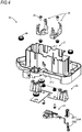
- Fig. 3 is a perspective view of a second connector 20.
- Fig. 4 is an exploded perspective view of the second connector 20.
- the second connector 20 corresponds to an example of a mating connector mentioned in the connector of the disclosure and an example of the second connector constituting the connector assembly of the disclosure.
- the second connector 20 includes a housing 21.
- the housing 21 has a fitting opening facing the fitting opening of the first connector 10 and for fitting with the first connector 10.
- the fitting sequence of fitting the first connector 10 and the second connector 20 together is shown in Figs. 7A to 11B and described in the corresponding description below.
- a cam pin 212 that is inserted into the pivot cam groove 151 of the lever 15 provided in the first connector 10 protrudes on the side surface of the housing 21.
- the housing 21 corresponds to an example of the second housing.
- the second connector 20 is provided with a main contact 22.
- the main contact 22 is a circuit terminal that is connected to the main contact 12 of the first connector 10 to pass large current therethrough.
- the main contact 22 corresponds to an example of the second main contact.
- the second connector 20 is provided with an interlock wire harness 23.
- the interlock wire harness 23 includes a sub-connector 23A that includes a sub-housing 231 and a sub-contact 232 provided inside the sub-housing 231.
- the sub-contact 232 provided inside the sub-housing 231 constituting the sub-connector 23A corresponds to an example of the second sub-contact.
- the sub-connector 23A is a connector for detecting fitting, and a fitting/separating signal is transmitted to a controller (not shown) via the interlock wire harness 23.
- the second connector 20 includes a fuse holding spring 24.
- the fuse holding spring 24 is a part for holding the fuse 121 of the main contact 12 of the first connector 10 when he second connector 20 is fitted with the first connector 10.
- Figs. 5A and 5B are an enlarged perspective view and an enlarged side view of the sub-housing 13 provided in the first connector 10.
- the sub-housing 13 is provided with an erroneous fitting prevention part 132.
- the erroneous fitting prevention part 132 extends in a cantilever shape in a fitting direction in which the first connector 10 and the second connector 20 are fitted.
- the fitting direction may be the upper-lower or up and down direction.
- the erroneous fitting prevention part 132 has a slanting surface 132a formed at a tip thereof. Further, a convex portion 132b protruding laterally with respect to the upper-lower direction is formed on the erroneous fitting prevention part 132. The operation of the erroneous fitting prevention part 132 will be described later.
- the erroneous fitting prevention part 132 corresponds to an example of the erroneous fitting prevention part mentioned in the connector of the disclosure and an example of the first erroneous fitting prevention part mentioned in the connector assembly of the disclosure. Further, the slanting surface 132a corresponds to an example of the tip portion mentioned in the disclosure.
- Figs. 6A to 6C are a plan view, a sectional view, and an enlarged view of the circle portion R in the sectional view of the housing 21 constituting the second connector 20.
- An erroneous fitting prevention protrusion 213 protruding upward is provided on the housing 21.
- the slanting surface 132a at the tip of the erroneous fitting prevention part 132 of the sub-housing 13 shown in Fig. 5 abuts against a top surface 213a of the erroneous fitting prevention protrusion 213 formed into a slanting surface, so that the sub-contact 14 of the first connector 10 and the sub-contact 232 of the second connector 20 are prevented from being connected to each other.
- a concave portion 213b is formed on a side surface of the erroneous fitting prevention protrusion 213.
- the erroneous fitting prevention protrusion 213 corresponds to an example of the second erroneous fitting prevention part mentioned in the disclosure.
- Figs. 7A and 7B are a side view and a sectional view showing an initial state of fitting in which the first connector 10 is stacked on the second connector 20. However, in Fig. 7A , the side surface opposite to the side surface shown in Fig. 1 appears.
- the lever 15 is still in an upright state and is in a pivot start position. Further, as shown in Fig. 7A , the cam pin 212 of the housing 21 of the second connector 20 is inserted into the pivot cam groove 151. Further, as shown in Fig. 7B , the sub-housing 13 is located directly above the erroneous fitting prevention protrusion 213 provided on the housing 21 of the second connector 20. At this time, the sub-contact 14 of the first connector 10 is not connected with the sub-contact 232 of the second connector 20. The sub-housing 13 is in a regular initial position before fitting.
- the correlation state between the first connector 10 and the second connector 20 shown in Figs. 7A and 7B is referred to as an initial state of regular fitting.
- Figs. 8A and 8B are a side view and a sectional view showing an initial state of non-regular fitting of the first connector 10 and the second connector 20 when the sub-housing 13 is on a position (non-regular initial position) deviated from the regular initial position.
- Fig. 8A the slide cam pin 131 provided in the sub-housing 13 is moved downward as compared with Fig. 7A . Further, as can be seen by comparing Fig. 7B and Fig. 8B , the sub-connector 13 is moved downward. However, only the sub-housing 13 is moved downward, and the parts of the first connector 10 other than the sub-connector 13 are located at the same height position in Figs. 7A and 7B , and Figs. 8A and 8B . For example, the lever 15 is in the pivot start position.
- the sub-housing 13 is supported on the main housing 11 to be slidable in the upper and lower direction. Therefore, due to some mistake or careless force, the sub housing 13, which should be normally arranged at the height shown in Figs. 7A and 7B , may be moved downward to the position shown in Figs. 8A and 8B .
- the sub-housing 13 even when the sub-housing 13 is moved to the non-regular initial position in the initial state of non-regular fitting, there is a structure preventing an occurrence of an accident in which the sub-contacts 14, 232 are connected to each other prior to the sliding operation (hereinafter, refer to Figs. 10A to 11B and the corresponding description) of the lever 15 (the first connector 10 and the second connector 20 are erroneously fitted). Further, the connection of the sub-contacts 14, 232 to each other is always performed by the sliding operation of the lever 15.
- Figs. 9A and 9B are a side view and a sectional view showing a state during fitting.
- Figs. 9A and 9B the lever 15 is pivoted halfway.
- the cam pin 212 inserted into the pivot cam groove 151 is pushed downward according to the shape of the pivot cam groove 151, and the main housing 11 of the first connector 10 moves closer to the second connector 20 toward a fitting completed position (that is, moves downward in the drawing).
- the main contact 12 (see Fig. 1 ) provided in the main housing 11 also moves downward together with the main housing 11.
- the sub-housing 13 also moves downward together with the main housing 11. Comparing Fig. 8A and Fig. 9A , the relative position of the slide cam pin 131 of the sub-housing 13 to the main housing 11 is the same. From this, it can be seen that the sub-housing 13 is moving downward together with the main housing 11.
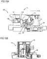
- Figs. 10A and 10B are a side view and a sectional view showing a state in which the lever is pivoted to a pivot end position.
- the main housing 11 is in a position further lowered toward the second connector 20 according to the shape of the pivot cam groove 151.
- the erroneous fitting prevention part 132 is in contact with the erroneous fitting prevention protrusion 213, and the sub-housing 13 remains at the same height position as Fig. 9B . If the erroneous fitting prevention part 132 and the erroneous fitting prevention protrusion 213 are not formed, the sub-housing 13 moves further downward together with the main housing 11 when moving from the state of Fig. 9B to the state of Fig. 10B .
- the sub-housing 13 remains at the height position where the erroneous fitting prevention part 132 is in contact with the erroneous fitting prevention protrusion 213, so that there is no risk of erroneous detection. In this way, the sub-housing 13 remains at the height position of the sub-housing 13 until the lever 15 moves from the angle shown in Figs. 9A and 9B to the final angle shown in Figs. 10A and 10B . Therefore, when the lever 15 is pivoted to the final angle shown in Figs.
- the sub-housing 13 is in the same state as when it is in the regular initial position shown in Figs. 7A and 7B in the fitting initial state. Further, when the lever 15 is pivoted to the final angle shown in Figs. 10A and 10B , the slide cam pin 131 is inserted into the slide cam groove 153.
- the lever 15 is slid in a direction different from the fitting direction of both connectors such as in the direction of the arrow A shown in Fig. 10A .
- the lever 15 is slid in a direction A intersecting the fitting direction.
- the direction A may intersect the fitting direction at least substantially perpendicularly.
- the cam pin 212 inserted into the pivot cam groove 151 moves through a horizontally extending portion of the pivot cam groove 151 to be substantially horizontally with respect to the lever 15.
- the slide guide groove 152 also extends horizontally, and the boss 111 inserted into the slide guide groove 152 also moves substantially horizontally with respect to the lever 15. That is, the height of the main housing 11 does not change substantially depending on the sidling of the lever 15 in the direction of the arrow A, and the main housing 11 remains at about the same height as before the sliding.
- the slide cam groove 153 extends downward diagonally.
- the slide cam pin 131 of the sub-housing 13 is inserted into the slide cam groove 153. Therefore, when the lever 15 is slid in the direction of the arrow A, the sub-housing 13 is further moved downward.
- Figs. 11A and 11B are a side view and a sectional view showing a state after the lever is slid in the direction of the arrow A.
- the sub-housing 13 is in a position further lowered as compared with Fig. 10B .
- the erroneous fitting prevention part 132 of the sub-housing 13 temporarily bends in a direction intersecting the fitting direction, and the contact with the erroneous fitting prevention protrusion 213 is released. At this time, the erroneous fitting prevention part 132 may bend laterally. Further, the lever 15 is further slid in the direction of the arrow A to move the sub-housing 13 downward, and finally, the convex portion 132b (see Fig. 5 ) of the erroneous fitting prevention part 132 of the sub-housing 13 is inserted into the concave portion 213b (see Fig. 6 ) on the side surface of the erroneous fitting prevention protrusion 213.
- the present embodiment includes the erroneous fitting prevention part 132 and the erroneous fitting prevention protrusion 213, the erroneous fitting is prevented. Further, in the present embodiment, the lever 15 is correctly operated regardless of the height position of the sub-housing 13 in the fitting initial state.
Landscapes
- Physics & Mathematics (AREA)
- Electromagnetism (AREA)
- Details Of Connecting Devices For Male And Female Coupling (AREA)
Abstract
Description
- The disclosure relates to a connector and a connector assembly that are mounted as parts of, for example, electric vehicles and hybrid vehicles and that relay current supplied from a power supply system.
- In electric vehicles and hybrid vehicles, connector devices capable of passing large current of, for example, 100 amperes are used. In situations such as maintenance, it may be necessary to separate (two) fitted connectors in this connector device. In that case, it is necessary to stop the flow of the flowing current and then separate the connectors in order to avoid electric shock. Therefore, a mechanism for reliably stopping the flow of current before separating the fitted connectors is required.
-
JP-A-2002-343169 - The lever pivots to connect the main contact, and then, slides to connect the sub-contact. The fitting of the connectors is detected by the connection of the sub-contact, and then, a high current flows through the main contact. When releasing the fitting, first, the lever is slid. This releases the connection of the sub-contact, which leads to cutting off of the high current. Thereafter, the connectors are separated by pivoting the lever. With this sequence, the connectors are separated from each other after the high current has been cut off.
- According to one advantageous aspect of the disclosure, there is provided a connector configured to be fitted with a mating connector, the connector including: a main housing; a first main contact provided in the main housing for main power conduction; a sub-housing supported on the main housing to be slidable in a fitting direction in which the connecter is fitted with the mating connector; a first sub-contact provided in the sub-housing for detecting a fitting of the connector with the mating connector; and an operating member pivotably and slidably supported on the main housing, wherein the connector is configured such that the main housing moves closer to the mating connector when the operating member is pivoted from a first position or posture to a second position or posture, wherein the first main contact contacts or conducts with a second main contact of the mating connector for main power conduction when the operating member reaches the second posture, wherein the sub-housing moves further in the fitting direction and the first sub-contact contacts or conducts with a second sub-contact of the mating connector for detecting the fitting when the operating member slides from the second posture in a direction different from the fitting direction, wherein the sub-housing or the first sub-contact includes an erroneous fitting prevention part configured to abut against the mating connector to prevent the first sub-contact from coming into contact with the second sub-contact when the sub-housing or the first sub-contact slides in the fitting direction with respect to the main housing in a state of incomplete fitting before the connector is completely fitted with the mating connector, and wherein the erroneous fitting prevention part is configured to be released from abutting against the mating connector by sliding of the operating member from the second posture to contact or conduct the first sub-contact with the second sub-contact.
- The erroneous fitting prevention part may be a cantilevered part or may extend in a cantilever shape in the fitting direction and include a tip portion configured to abut against a housing of the mating connector. The erroneous fitting prevention part may be configured to be pushed in the fitting direction by the sliding of the operating member from the second posture and to be bent in a direction intersecting the fitting direction, so that abuttment of the tip portion with the housing of the mating connector is released.
- According to another advantageous aspect of the disclosure, there is provided a connector assembly including a first connector and a second connector which are fitted with each other, wherein the first connector comprises a main housing; a first main contact provided in the main housing for main power conduction; a first sub-housing supported on the main housing to be slidable in a fitting direction in which the first connector is connected with the second connector; a first sub-contact provided in the first sub-housing for detecting a fitting of the first connector with the second connector; and an operating member pivotably and slidably supported on the main housing, wherein the second connector comprises a second housing; a second main contact provided in the second housing for main power conduction; and a second sub-contact for detecting the fitting of the first connector with the second connector, wherein the connector assembly is configured such that the main housing moves closer to the second connector when the operating member is pivoted from a first position or posture to a second position or posture, wherein the first main contact contacts or conducts with the second main contact when the operating member reaches the second posture, wherein the first sub-housing moves further in the fitting direction with respect to the main housing and the first sub-contact contacts or conducts with the second sub-contact when the operating member slides from the second posture in a direction different from the fitting direction, wherein the second housing includes a second erroneous fitting prevention part configured to abut against the first sub-housing to prevent the first sub-contact from coming into contact with the second sub-contact when the first sub-housing slides in the fitting direction with respect to the main housing in a state of incomplete fitting before the first connector is completely fitted with the second connector at the time of fitting the first connector to the second connector, and wherein the first sub-housing or the first sub-contact includes a first erroneous fitting prevention part configured to abut against the second erroneous fitting prevention part to prevent the first sub-contact from coming into contact with the second sub-contact when the first sub-housing or the first sub-contact slides in the fitting direction with respect to the main housing in a state of the incomplete fitting and to be released from abutting against the second erroneous fitting prevention part by sliding of the operating member from the second posture to contact or conduct the first sub-contact with the second sub-contact.
- The connector and the connector assembly of the disclosure include the erroneous fitting prevention structure described above. Therefore, according to the disclosure, the sub-contact is prevented from being connected before the slide operation. Further, according to the disclosure, it is possible to reliably perform the pivoting operation and the subsequent sliding operation.
-
-
Fig. 1 is an external perspective view of a first connector. -
Fig. 2 is an exploded perspective view of the first connector. -
Fig. 3 is a perspective view of a second connector. -
Fig. 4 is an exploded perspective view of the second connector. -
Fig. 5A is an enlarged perspective view of a sub-housing constituting the first connector, andFig. 5B is an enlarged side view of the sub-housing constituting the first connector. -
Fig. 6A is a plan view of a housing constituting the second connector,Fig. 6B is a sectional view of the housing constituting the second connector, andFig. 6C is an enlarged view of the circled portion R inFig. 6B of the housing constituting the second connector. -
Fig. 7A is a side view andFig. 7B is a sectional view, showing an initial state of fitting in which the first connector is superimposed on the second connector. -
Fig. 8A is a side view andFig. 8B is a sectional view, showing the initial state of fitting when the sub-housing is in a misaligned state. -
Fig. 9A is a side view andFig. 9B is a sectional view, showing a state during fitting. -
Fig. 10A is a side view andFig. 10B is a sectional view, showing a state in which a lever has been pivoted to a final pivot position. -
Fig. 11A is a side view andFig. 11B is a sectional view, showing a state after the lever has been slid. - In the connector device provided with the main contact and the sub-contact, as described the background section above, it is necessary to reliably perform an operation of connecting the main contact by the pivoting operation of the lever and then connecting the sub-contact by the sliding operation. In the connector device including the main contact and the sub-contact, it is necessary to make the main contact and the sub-contact move independently. Therefore, depending on the structure of the connector device, some mistake may occur or a careless force may be applied to the connector, causing a problem in that the sub-contact is connected and a high current starts to flow before the connectors are completely fitted together. Further, there may be a problem in that the sliding operation cannot be performed after the pivoting operation of the lever.
- An object of the disclosure is to provide a connector and a connector assembly capable of preventing a sub-contact from being connected before a sliding operation of a lever has occurred and reliably performing a pivoting operation of the lever and a subsequent sliding operation.
- Hereinafter, embodiments of the disclosure will be described.
-
Fig. 1 is an external perspective view of afirst connector 10. - Further,
Fig. 2 is an exploded perspective view of thefirst connector 10. - The
first connector 10 corresponds to an example of the connector of the disclosure and an example of the first connector constituting the connector assembly of the disclosure. - The
first connector 10 includes amain housing 11 and a main contact 12. Themain housing 11 may have an opening at least in a part thereof and may have a shape that is widely open in an upper and lower direction. Large current of, for example, 100 amperes flows through the main contact 12. The main contact 12 includes afuse 121 for preventing an overcurrent exceeding the standard. The main contact 12 is provided in themain housing 11 and is arranged, stored, or fixed in themain housing 11 through the opening, for example. The main contact 12 corresponds to an example of the first main contact mentioned in the disclosure. - Further, the
first connector 10 includes a sub-housing 13 and a sub-contact 14. The sub-contact 14 is a circuit terminal for detecting fitting. The sub-contact 14 is provided in the sub-housing 13 and is press-fitted into the sub-housing 13, for example. In the disclosure, the configuration in which the sub-housing 13 and the sub-contact 14 provided in the sub-housing 13 are combined is referred to as a sub-connector 13A. The sub-connector 13A is arranged to be slidable with the connector in an upper and lower or up and down or mating M and unmating U direction in themain housing 11. In the disclosure, the sub-housing 13 and the sub-contact 14 correspond to each example of the first sub-housing and the first sub-contact, respectively. In addition, a side of thefirst connector 10 in a state in which thefirst connector 10 is fitted with thesecond connector 20 is referred as the upper side, and a side of thesecond connector 20 in such a state is referred as the lower side, in the description of embodiments for descriptive purposes only. The first connector can however be orientated differently from the orientation shown inFig. 2 . - The
first connector 10 further includes alever 15. Thelever 15 is pivotably and slidably attached to themain housing 11, as shown inFig. 1 . For example, thelever 15 has two side surfaces or members connected by a handle and is attached so that both side surfaces straddle themain housing 11. Thelever 15 can be pivoted and slid by an operation of a user. Apivot cam groove 151 and aslide guide groove 152 are formed in at least one of the two side surfaces of thelever 15 straddling themain housing 11. Further, aslide cam groove 153 for sliding the sub-housing 13 by a sliding operation is formed in at least one of the two side surfaces of thelever 15 straddling themain housing 11. Themain housing 11 is provided with aboss 111 that is a central axis of pivot of thelever 15. As shown inFig. 1 , theboss 111 is inserted into theslide guide groove 152. Theboss 111 serves not only as a central axis of pivot of thelever 15, but also as a guide for sliding thelever 15. Further, the sub-housing 13 is formed with aslide cam pin 131 that is inserted into theslide cam groove 153. In the disclosure, thelever 15 corresponds to an example of an operating member. - The
first connector 10 may further include alid 16. The main contact 12 and the sub-connector 13A are arranged in themain housing 11, and then, themain housing 11 is covered with thelid 16. When themain housing 11 is covered with thelid 16, thefirst connector 10 becomes a connector having a fitting opening that is open on one side. -
Fig. 3 is a perspective view of asecond connector 20. - Further,
Fig. 4 is an exploded perspective view of thesecond connector 20. - The
second connector 20 corresponds to an example of a mating connector mentioned in the connector of the disclosure and an example of the second connector constituting the connector assembly of the disclosure. - The
second connector 20 includes ahousing 21. Thehousing 21 has a fitting opening facing the fitting opening of thefirst connector 10 and for fitting with thefirst connector 10. The fitting sequence of fitting thefirst connector 10 and thesecond connector 20 together is shown inFigs. 7A to 11B and described in the corresponding description below. Further, acam pin 212 that is inserted into thepivot cam groove 151 of thelever 15 provided in thefirst connector 10 protrudes on the side surface of thehousing 21. In the disclosure, thehousing 21 corresponds to an example of the second housing. - Further, the
second connector 20 is provided with amain contact 22. Themain contact 22 is a circuit terminal that is connected to the main contact 12 of thefirst connector 10 to pass large current therethrough. In the disclosure, themain contact 22 corresponds to an example of the second main contact. - Further, the
second connector 20 is provided with aninterlock wire harness 23. Theinterlock wire harness 23 includes a sub-connector 23A that includes a sub-housing 231 and a sub-contact 232 provided inside the sub-housing 231. In the disclosure, the sub-contact 232 provided inside the sub-housing 231 constituting the sub-connector 23A corresponds to an example of the second sub-contact. The sub-connector 23A is a connector for detecting fitting, and a fitting/separating signal is transmitted to a controller (not shown) via theinterlock wire harness 23. - Furthermore, the
second connector 20 includes afuse holding spring 24. Thefuse holding spring 24 is a part for holding thefuse 121 of the main contact 12 of thefirst connector 10 when hesecond connector 20 is fitted with thefirst connector 10. - In
Fig. 4 , screws 25 andcollars 26 for screwing members are further shown, but their description will be omitted. -
Figs. 5A and 5B are an enlarged perspective view and an enlarged side view of the sub-housing 13 provided in thefirst connector 10. - The sub-housing 13 is provided with an erroneous
fitting prevention part 132. The erroneousfitting prevention part 132 extends in a cantilever shape in a fitting direction in which thefirst connector 10 and thesecond connector 20 are fitted. The fitting direction may be the upper-lower or up and down direction. The erroneousfitting prevention part 132 has aslanting surface 132a formed at a tip thereof. Further, aconvex portion 132b protruding laterally with respect to the upper-lower direction is formed on the erroneousfitting prevention part 132. The operation of the erroneousfitting prevention part 132 will be described later. The erroneousfitting prevention part 132 corresponds to an example of the erroneous fitting prevention part mentioned in the connector of the disclosure and an example of the first erroneous fitting prevention part mentioned in the connector assembly of the disclosure. Further, the slantingsurface 132a corresponds to an example of the tip portion mentioned in the disclosure. -
Figs. 6A to 6C are a plan view, a sectional view, and an enlarged view of the circle portion R in the sectional view of thehousing 21 constituting thesecond connector 20. - An erroneous
fitting prevention protrusion 213 protruding upward is provided on thehousing 21. The slantingsurface 132a at the tip of the erroneousfitting prevention part 132 of the sub-housing 13 shown inFig. 5 abuts against atop surface 213a of the erroneousfitting prevention protrusion 213 formed into a slanting surface, so that the sub-contact 14 of thefirst connector 10 and the sub-contact 232 of thesecond connector 20 are prevented from being connected to each other. Further, aconcave portion 213b is formed on a side surface of the erroneousfitting prevention protrusion 213. The erroneousfitting prevention protrusion 213 corresponds to an example of the second erroneous fitting prevention part mentioned in the disclosure. - Next, the movement of both connectors at the time of fitting will be described. In each of the drawings after
Fig. 7A described below, the sub-contact 14 and the sub-connector 23A of thesecond connector 20 are not shown in order to clearly show the present embodiment. The sub-housing 13 is shown because it is necessary for the explanation of the present embodiment. -
Figs. 7A and 7B are a side view and a sectional view showing an initial state of fitting in which thefirst connector 10 is stacked on thesecond connector 20. However, inFig. 7A , the side surface opposite to the side surface shown inFig. 1 appears. - Here, the
lever 15 is still in an upright state and is in a pivot start position. Further, as shown inFig. 7A , thecam pin 212 of thehousing 21 of thesecond connector 20 is inserted into thepivot cam groove 151. Further, as shown inFig. 7B , the sub-housing 13 is located directly above the erroneousfitting prevention protrusion 213 provided on thehousing 21 of thesecond connector 20. At this time, the sub-contact 14 of thefirst connector 10 is not connected with the sub-contact 232 of thesecond connector 20. The sub-housing 13 is in a regular initial position before fitting. - The correlation state between the
first connector 10 and thesecond connector 20 shown inFigs. 7A and 7B is referred to as an initial state of regular fitting. -
Figs. 8A and 8B are a side view and a sectional view showing an initial state of non-regular fitting of thefirst connector 10 and thesecond connector 20 when the sub-housing 13 is on a position (non-regular initial position) deviated from the regular initial position. - As can be seen by comparing
Fig. 7A andFig. 8A , inFig. 8A , theslide cam pin 131 provided in the sub-housing 13 is moved downward as compared withFig. 7A . Further, as can be seen by comparingFig. 7B andFig. 8B , the sub-connector 13 is moved downward. However, only the sub-housing 13 is moved downward, and the parts of thefirst connector 10 other than the sub-connector 13 are located at the same height position inFigs. 7A and 7B , andFigs. 8A and 8B . For example, thelever 15 is in the pivot start position. - The sub-housing 13 is supported on the
main housing 11 to be slidable in the upper and lower direction. Therefore, due to some mistake or careless force, thesub housing 13, which should be normally arranged at the height shown inFigs. 7A and 7B , may be moved downward to the position shown inFigs. 8A and 8B . In the case of the present embodiment, even when the sub-housing 13 is moved to the non-regular initial position in the initial state of non-regular fitting, there is a structure preventing an occurrence of an accident in which the sub-contacts 14, 232 are connected to each other prior to the sliding operation (hereinafter, refer toFigs. 10A to 11B and the corresponding description) of the lever 15 (thefirst connector 10 and thesecond connector 20 are erroneously fitted). Further, the connection of the sub-contacts 14, 232 to each other is always performed by the sliding operation of thelever 15. - Hereinafter, the movement of each member when the user tries to fit the
first connector 10 and thesecond connector 20 in a state where the sub-housing 13 is moved downward to the non-regular initial position shown inFigs. 8A and 8B will be described. -
Figs. 9A and 9B are a side view and a sectional view showing a state during fitting. - In
Figs. 9A and 9B , thelever 15 is pivoted halfway. At this time, thecam pin 212 inserted into thepivot cam groove 151 is pushed downward according to the shape of thepivot cam groove 151, and themain housing 11 of thefirst connector 10 moves closer to thesecond connector 20 toward a fitting completed position (that is, moves downward in the drawing). The main contact 12 (seeFig. 1 ) provided in themain housing 11 also moves downward together with themain housing 11. Furthermore, the sub-housing 13 also moves downward together with themain housing 11. ComparingFig. 8A andFig. 9A , the relative position of theslide cam pin 131 of the sub-housing 13 to themain housing 11 is the same. From this, it can be seen that the sub-housing 13 is moving downward together with themain housing 11. - When the
lever 15 is pivoted from the pivot start position to an angle shown inFigs. 9A and 9B , as shown inFig. 9B , the slantingsurface 132a (seeFig. 5 ) at the tip of the erroneousfitting prevention part 132 of the sub-housing 13 abuts against thetop surface 213a of the erroneous fitting prevention protrusion 213 (seeFig. 6C ). -
Figs. 10A and 10B are a side view and a sectional view showing a state in which the lever is pivoted to a pivot end position. - Comparing
Figs. 10A and 10B andFigs. 9A and 9B , themain housing 11 is in a position further lowered toward thesecond connector 20 according to the shape of thepivot cam groove 151. However, as shown inFig. 10B , the erroneousfitting prevention part 132 is in contact with the erroneousfitting prevention protrusion 213, and the sub-housing 13 remains at the same height position asFig. 9B . If the erroneousfitting prevention part 132 and the erroneousfitting prevention protrusion 213 are not formed, the sub-housing 13 moves further downward together with themain housing 11 when moving from the state ofFig. 9B to the state ofFig. 10B . That is, it may be erroneously detected that the sub-contacts 14, 232 are connected to each other by thelever 15 being regularly slid. In the case of the present embodiment, the sub-housing 13 remains at the height position where the erroneousfitting prevention part 132 is in contact with the erroneousfitting prevention protrusion 213, so that there is no risk of erroneous detection. In this way, the sub-housing 13 remains at the height position of the sub-housing 13 until thelever 15 moves from the angle shown inFigs. 9A and 9B to the final angle shown inFigs. 10A and 10B . Therefore, when thelever 15 is pivoted to the final angle shown inFigs. 10A and 10B , the sub-housing 13 is in the same state as when it is in the regular initial position shown inFigs. 7A and 7B in the fitting initial state. Further, when thelever 15 is pivoted to the final angle shown inFigs. 10A and 10B , theslide cam pin 131 is inserted into theslide cam groove 153. - Thereafter, the
lever 15 is slid in a direction different from the fitting direction of both connectors such as in the direction of the arrow A shown inFig. 10A . For example, thelever 15 is slid in a direction A intersecting the fitting direction. The direction A may intersect the fitting direction at least substantially perpendicularly. During this sliding operation, thecam pin 212 inserted into thepivot cam groove 151 moves through a horizontally extending portion of thepivot cam groove 151 to be substantially horizontally with respect to thelever 15. Further, theslide guide groove 152 also extends horizontally, and theboss 111 inserted into theslide guide groove 152 also moves substantially horizontally with respect to thelever 15. That is, the height of themain housing 11 does not change substantially depending on the sidling of thelever 15 in the direction of the arrow A, and themain housing 11 remains at about the same height as before the sliding. - On the other hand, the
slide cam groove 153 extends downward diagonally. Theslide cam pin 131 of the sub-housing 13 is inserted into theslide cam groove 153. Therefore, when thelever 15 is slid in the direction of the arrow A, the sub-housing 13 is further moved downward. -
Figs. 11A and 11B are a side view and a sectional view showing a state after the lever is slid in the direction of the arrow A. - As shown in
Fig. 11B , the sub-housing 13 is in a position further lowered as compared withFig. 10B . - When the
lever 15 is slid in the direction of the arrow A from the state shown inFigs. 10A and 10B , the erroneousfitting prevention part 132 of the sub-housing 13 temporarily bends in a direction intersecting the fitting direction, and the contact with the erroneousfitting prevention protrusion 213 is released. At this time, the erroneousfitting prevention part 132 may bend laterally. Further, thelever 15 is further slid in the direction of the arrow A to move the sub-housing 13 downward, and finally, theconvex portion 132b (seeFig. 5 ) of the erroneousfitting prevention part 132 of the sub-housing 13 is inserted into theconcave portion 213b (seeFig. 6 ) on the side surface of the erroneousfitting prevention protrusion 213. - As described above, since the present embodiment includes the erroneous
fitting prevention part 132 and the erroneousfitting prevention protrusion 213, the erroneous fitting is prevented. Further, in the present embodiment, thelever 15 is correctly operated regardless of the height position of the sub-housing 13 in the fitting initial state. - When releasing the fitted state of the connector, a reverse operation with respect to the above-described fitting operation is performed. That is, first, the
lever 15 is slid in the direction of the arrow B shown inFig. 11A . Then, only the sub-housing 13 is lifted to the position shown inFig. 10 . At this stage, it is detected that the fitting of the sub-connectors 13A, 23A to each other is released and the separation operation is performed. In order to cut off large current passing through themain contacts 12, 22, although it is a short period of time, a certain period time is required from the detection that the separation operation is performed. In the present embodiment, the connection of themain contacts 12, 22 is released by the pivot operation of thelever 15 after the slide operation. Even when the pivot operation is continuously performed after the slide operation, a certain time for cutting off large current is sufficiently provided. - When the
lever 15 is slid in the direction of the arrow B, and then, thelever 15 is pivoted from the position shown inFig. 11A toward the position shown inFig. 7A , thefirst connector 10 can be separated from thesecond connector 20.
Claims (3)
- A connector (10) configured to be fitted with a mating connector (20), the connector (10) comprising:a main housing (11);a first main contact (12) provided in the main housing (11) for main power conduction;a sub-housing (13) supported on the main housing (11) to be slidable in a fitting direction in which the connecter (10) is fitted with the mating connector (20);a first sub-contact (14) provided in the sub-housing (13) for detecting a fitting of the connector (10) with the mating connector (20); andan operating member (15) pivotably and slidably supported on the main housing (11),wherein the main housing (11) moves closer to the mating connector (20) when the operating member (15) is pivoted from a first position to a second position,wherein the first main contact (12) contacts with a second main contact (22) of the mating connector (20) for main power conduction when the operating member (15) reaches the second position,wherein the sub-housing (13) moves further in the fitting direction and the first sub-contact (14) contacts with a second sub-contact (232) of the mating connector (20) for detecting the fitting when the operating member (15) slides from the second position in a direction different from the fitting direction,wherein the sub-housing (13) includes an erroneous fitting prevention part (132) configured to abut against the mating connector (20) to prevent the first sub-contact (14) from coming into contact with the second sub-contact (232) when the sub-housing (13) slides in the fitting direction with respect to the main housing (11) in a state of incomplete fitting before the connector (10) is completely fitted with the mating connector (20), andwherein the erroneous fitting prevention part (132) is configured to be released from abutting against the mating connector (20) by sliding of the operating member (15) from the second position to contact the first sub-contact (14) with the second sub-contact (232).
- The connector (10) according to claim 1,
wherein the erroneous fitting prevention part (132) extends in a cantilever shape in the fitting direction and includes a tip portion (132a) configured to abut against a housing (21) of the mating connector (20), and
wherein the erroneous fitting prevention part (132) is configured to be pushed in the fitting direction by the sliding of the operating member (15) from the second position and to be bent in a direction intersecting the fitting direction, so that abuttment of the tip portion (132a) with the housing (21) of the mating connector (20) is released. - A connector assembly comprising a first connector (10) and a second connector (20) which are fitted with each other,
wherein the first connector (10) comprises
a main housing (11);
a first main contact (12) provided in the main housing (11) for main power conduction;
a first sub-housing (13) supported on the main housing (11) to be slidable in a fitting direction in which the first connector (10) is connected with the second connector (20);
a first sub-contact (14) provided in the first sub-housing (13) for detecting a fitting of the first connector (10) with the second connector (20); and
an operating member (15) pivotably and slidably supported on the main housing (11),
wherein the second connector (20) comprises
a second housing (21);
a second main contact (22) provided in the second housing (21) for main power conduction; and
a second sub-contact (232) for detecting the fitting of the first connector (10) with the second connector (20),
wherein the main housing (11) moves closer to the second connector (20) when the operating member (15) is pivoted from a first position to a second position,
wherein the first main contact (12) contacts with the second main contact (22) when the operating member (15) reaches the second position,
wherein the first sub-housing (13) moves further in the fitting direction with respect to the main housing (11) and the first sub-contact (14) contacts with the second sub-contact (232) when the operating member (15) slides from the second position in a direction different from the fitting direction,
wherein the second housing (21) includes a second erroneous fitting prevention part (231) configured to abut against the first sub-housing (13) to prevent the first sub-contact (14) from coming into contact with the second sub-contact (232) when the first sub-housing (13) slides in the fitting direction with respect to the main housing (11) in a state of incomplete fitting before the first connector (10) is completely fitted with the second connector (20) at the time of fitting the first connector (10) to the second connector (20), and
wherein the first sub-housing (13) includes a first erroneous fitting prevention part (132) configured to abut against the second erroneous fitting prevention part (213) to prevent the first sub-contact (14) from coming into contact with the second sub-contact (232) when the first sub-housing (14) slides in the fitting direction with respect to the main housing (11) in a state of the incomplete fitting and to be released from abutting against the second erroneous fitting prevention part (231) by sliding of the operating member (15) from the second position to contact the first sub-contact (14) with the second sub-contact (232).
Applications Claiming Priority (1)
| Application Number | Priority Date | Filing Date | Title |
|---|---|---|---|
| JP2020097183A JP7525309B2 (en) | 2020-06-03 | 2020-06-03 | Connector and connector assembly |
Publications (2)
| Publication Number | Publication Date |
|---|---|
| EP3920341A1 true EP3920341A1 (en) | 2021-12-08 |
| EP3920341B1 EP3920341B1 (en) | 2024-02-07 |
Family
ID=76059667
Family Applications (1)
| Application Number | Title | Priority Date | Filing Date |
|---|---|---|---|
| EP21175150.8A Active EP3920341B1 (en) | 2020-06-03 | 2021-05-21 | Connector and connector assembly |
Country Status (4)
| Country | Link |
|---|---|
| US (1) | US11677184B2 (en) |
| EP (1) | EP3920341B1 (en) |
| JP (1) | JP7525309B2 (en) |
| CN (1) | CN113764216B (en) |
Cited By (1)
| Publication number | Priority date | Publication date | Assignee | Title |
|---|---|---|---|---|
| CN115173153A (en) * | 2022-08-16 | 2022-10-11 | 金有逍 | Power distribution terminal misconnection prevention device |
Families Citing this family (4)
| Publication number | Priority date | Publication date | Assignee | Title |
|---|---|---|---|---|
| JP7638845B2 (en) * | 2021-10-06 | 2025-03-04 | 日本航空電子工業株式会社 | Connector device |
| JP1730747S (en) * | 2022-05-20 | 2022-11-28 | connector | |
| JP1730744S (en) * | 2022-05-20 | 2022-11-28 | connector | |
| WO2025254189A1 (en) * | 2024-06-07 | 2025-12-11 | TE Connectivity Japan合同会社 | Connector assembly |
Citations (2)
| Publication number | Priority date | Publication date | Assignee | Title |
|---|---|---|---|---|
| JP2002343169A (en) | 2001-05-16 | 2002-11-29 | Yazaki Corp | Lever fitting type power supply circuit breaker |
| EP2811586A1 (en) * | 2013-06-06 | 2014-12-10 | Japan Aviation Electronics Industry Limited | Connector device |
Family Cites Families (16)
| Publication number | Priority date | Publication date | Assignee | Title |
|---|---|---|---|---|
| JP2531000Y2 (en) * | 1991-10-14 | 1997-04-02 | 住友電装株式会社 | connector |
| EP0599332B1 (en) * | 1992-11-27 | 1997-03-19 | Sumitomo Wiring Systems, Ltd. | Lever-operated connector |
| JP2772309B2 (en) * | 1993-03-17 | 1998-07-02 | 矢崎総業株式会社 | Lever connection type connector |
| JP2817088B2 (en) * | 1994-02-23 | 1998-10-27 | 矢崎総業株式会社 | Lever lock reinforcement structure |
| JP4943995B2 (en) | 2007-11-05 | 2012-05-30 | 矢崎総業株式会社 | Lever type connector |
| US7789690B1 (en) * | 2009-10-08 | 2010-09-07 | Tyco Electronics Corporation | Connector assembly having multi-stage latching sequence |
| JP5594008B2 (en) * | 2010-09-15 | 2014-09-24 | 住友電装株式会社 | connector |
| TWI478137B (en) * | 2011-04-27 | 2015-03-21 | Sony Corp | Display device |
| JP6099203B2 (en) * | 2013-09-03 | 2017-03-22 | 日本航空電子工業株式会社 | Connector device |
| JP6182515B2 (en) * | 2014-08-19 | 2017-08-16 | 日本航空電子工業株式会社 | Connector device |
| DE102014115252A1 (en) * | 2014-10-20 | 2016-04-21 | Phoenix Contact Gmbh & Co. Kg | Electrical connector pair |
| JP6315346B2 (en) * | 2015-01-16 | 2018-04-25 | 住友電装株式会社 | connector |
| JP6663790B2 (en) * | 2016-05-12 | 2020-03-13 | 日本航空電子工業株式会社 | Connector device |
| JP6634347B2 (en) * | 2016-06-20 | 2020-01-22 | 日本航空電子工業株式会社 | Power circuit breaker |
| JP6692718B2 (en) * | 2016-08-16 | 2020-05-13 | 日本航空電子工業株式会社 | Connector device |
| JP6929821B2 (en) | 2018-06-26 | 2021-09-01 | タイコエレクトロニクスジャパン合同会社 | Electrical connector |
-
2020
- 2020-06-03 JP JP2020097183A patent/JP7525309B2/en active Active
-
2021
- 2021-05-21 EP EP21175150.8A patent/EP3920341B1/en active Active
- 2021-06-02 US US17/336,572 patent/US11677184B2/en active Active
- 2021-06-03 CN CN202110618363.1A patent/CN113764216B/en active Active
Patent Citations (2)
| Publication number | Priority date | Publication date | Assignee | Title |
|---|---|---|---|---|
| JP2002343169A (en) | 2001-05-16 | 2002-11-29 | Yazaki Corp | Lever fitting type power supply circuit breaker |
| EP2811586A1 (en) * | 2013-06-06 | 2014-12-10 | Japan Aviation Electronics Industry Limited | Connector device |
Cited By (1)
| Publication number | Priority date | Publication date | Assignee | Title |
|---|---|---|---|---|
| CN115173153A (en) * | 2022-08-16 | 2022-10-11 | 金有逍 | Power distribution terminal misconnection prevention device |
Also Published As
| Publication number | Publication date |
|---|---|
| CN113764216B (en) | 2024-12-24 |
| US20210384672A1 (en) | 2021-12-09 |
| EP3920341B1 (en) | 2024-02-07 |
| CN113764216A (en) | 2021-12-07 |
| JP2021190380A (en) | 2021-12-13 |
| JP7525309B2 (en) | 2024-07-30 |
| US11677184B2 (en) | 2023-06-13 |
Similar Documents
| Publication | Publication Date | Title |
|---|---|---|
| EP3920341B1 (en) | Connector and connector assembly | |
| CN108475884B (en) | Connector system with connector position assurance | |
| US10038278B2 (en) | Electrical connector having a connector position assurance element | |
| US9680256B1 (en) | Connector system with connector position assurance | |
| US4902968A (en) | Connector terminal checking tool | |
| US5672073A (en) | Connector having engagement detecting device | |
| JP5329330B2 (en) | Connector assembly | |
| EP3416247A1 (en) | Connector system with low profile connector position assurance device | |
| EP1939991A2 (en) | A connector and a connector assembly | |
| KR100219361B1 (en) | Connector | |
| EP0624925A1 (en) | Connector with fitting detection function | |
| CN102484332B (en) | Electrical connector with shorting bar operator | |
| JP2009532846A (en) | Electronic connector with locking mechanism | |
| JP2019067714A (en) | Connector and connector assembly | |
| EP2541688A2 (en) | Electrical Connector | |
| CN100536251C (en) | Connector and method for controlling the assembly thereof | |
| JP4843669B2 (en) | Electrical connector with locking mechanism | |
| JP2009117096A (en) | Lever type connector | |
| US8636537B2 (en) | Connecting terminal | |
| CN114520436A (en) | Electric connection structure | |
| EP3082200B1 (en) | Electrical connector system with connector position assurance | |
| EP4080690A1 (en) | Connector apparatus with switch for improving contact reliability | |
| EP4312323A1 (en) | Connector assembly | |
| CN114256687B (en) | Electrical connector assembly having a mating lever and a connector position assurance member | |
| JPH03117584A (en) | Automatic tool exchanging device |
Legal Events
| Date | Code | Title | Description |
|---|---|---|---|
| PUAI | Public reference made under article 153(3) epc to a published international application that has entered the european phase |
Free format text: ORIGINAL CODE: 0009012 |
|
| STAA | Information on the status of an ep patent application or granted ep patent |
Free format text: STATUS: REQUEST FOR EXAMINATION WAS MADE |
|
| 17P | Request for examination filed |
Effective date: 20210521 |
|
| AK | Designated contracting states |
Kind code of ref document: A1 Designated state(s): AL AT BE BG CH CY CZ DE DK EE ES FI FR GB GR HR HU IE IS IT LI LT LU LV MC MK MT NL NO PL PT RO RS SE SI SK SM TR |
|
| B565 | Issuance of search results under rule 164(2) epc |
Effective date: 20211027 |
|
| GRAP | Despatch of communication of intention to grant a patent |
Free format text: ORIGINAL CODE: EPIDOSNIGR1 |
|
| STAA | Information on the status of an ep patent application or granted ep patent |
Free format text: STATUS: GRANT OF PATENT IS INTENDED |
|
| RIC1 | Information provided on ipc code assigned before grant |
Ipc: H01H 85/02 20060101ALN20230727BHEP Ipc: H01R 13/70 20060101ALN20230727BHEP Ipc: H01R 13/696 20110101ALN20230727BHEP Ipc: H01H 85/20 20060101ALI20230727BHEP Ipc: H01H 9/10 20060101ALI20230727BHEP Ipc: H01H 9/08 20060101ALI20230727BHEP Ipc: H01R 13/641 20060101ALI20230727BHEP Ipc: H01R 13/629 20060101AFI20230727BHEP |
|
| INTG | Intention to grant announced |
Effective date: 20230823 |
|
| GRAS | Grant fee paid |
Free format text: ORIGINAL CODE: EPIDOSNIGR3 |
|
| GRAA | (expected) grant |
Free format text: ORIGINAL CODE: 0009210 |
|
| STAA | Information on the status of an ep patent application or granted ep patent |
Free format text: STATUS: THE PATENT HAS BEEN GRANTED |
|
| AK | Designated contracting states |
Kind code of ref document: B1 Designated state(s): AL AT BE BG CH CY CZ DE DK EE ES FI FR GB GR HR HU IE IS IT LI LT LU LV MC MK MT NL NO PL PT RO RS SE SI SK SM TR |
|
| REG | Reference to a national code |
Ref country code: GB Ref legal event code: FG4D |
|
| REG | Reference to a national code |
Ref country code: CH Ref legal event code: EP |
|
| REG | Reference to a national code |
Ref country code: DE Ref legal event code: R096 Ref document number: 602021009152 Country of ref document: DE |
|
| REG | Reference to a national code |
Ref country code: IE Ref legal event code: FG4D |
|
| REG | Reference to a national code |
Ref country code: LT Ref legal event code: MG9D |
|
| REG | Reference to a national code |
Ref country code: NL Ref legal event code: MP Effective date: 20240207 |
|
| PG25 | Lapsed in a contracting state [announced via postgrant information from national office to epo] |
Ref country code: IS Free format text: LAPSE BECAUSE OF FAILURE TO SUBMIT A TRANSLATION OF THE DESCRIPTION OR TO PAY THE FEE WITHIN THE PRESCRIBED TIME-LIMIT Effective date: 20240607 |
|
| PG25 | Lapsed in a contracting state [announced via postgrant information from national office to epo] |
Ref country code: LT Free format text: LAPSE BECAUSE OF FAILURE TO SUBMIT A TRANSLATION OF THE DESCRIPTION OR TO PAY THE FEE WITHIN THE PRESCRIBED TIME-LIMIT Effective date: 20240207 |
|
| PG25 | Lapsed in a contracting state [announced via postgrant information from national office to epo] |
Ref country code: GR Free format text: LAPSE BECAUSE OF FAILURE TO SUBMIT A TRANSLATION OF THE DESCRIPTION OR TO PAY THE FEE WITHIN THE PRESCRIBED TIME-LIMIT Effective date: 20240508 |
|
| REG | Reference to a national code |
Ref country code: AT Ref legal event code: MK05 Ref document number: 1655978 Country of ref document: AT Kind code of ref document: T Effective date: 20240207 |
|
| PG25 | Lapsed in a contracting state [announced via postgrant information from national office to epo] |
Ref country code: NL Free format text: LAPSE BECAUSE OF FAILURE TO SUBMIT A TRANSLATION OF THE DESCRIPTION OR TO PAY THE FEE WITHIN THE PRESCRIBED TIME-LIMIT Effective date: 20240207 Ref country code: HR Free format text: LAPSE BECAUSE OF FAILURE TO SUBMIT A TRANSLATION OF THE DESCRIPTION OR TO PAY THE FEE WITHIN THE PRESCRIBED TIME-LIMIT Effective date: 20240207 Ref country code: RS Free format text: LAPSE BECAUSE OF FAILURE TO SUBMIT A TRANSLATION OF THE DESCRIPTION OR TO PAY THE FEE WITHIN THE PRESCRIBED TIME-LIMIT Effective date: 20240507 |
|
| PG25 | Lapsed in a contracting state [announced via postgrant information from national office to epo] |
Ref country code: ES Free format text: LAPSE BECAUSE OF FAILURE TO SUBMIT A TRANSLATION OF THE DESCRIPTION OR TO PAY THE FEE WITHIN THE PRESCRIBED TIME-LIMIT Effective date: 20240207 |
|
| PG25 | Lapsed in a contracting state [announced via postgrant information from national office to epo] |
Ref country code: AT Free format text: LAPSE BECAUSE OF FAILURE TO SUBMIT A TRANSLATION OF THE DESCRIPTION OR TO PAY THE FEE WITHIN THE PRESCRIBED TIME-LIMIT Effective date: 20240207 |
|
| PG25 | Lapsed in a contracting state [announced via postgrant information from national office to epo] |
Ref country code: RS Free format text: LAPSE BECAUSE OF FAILURE TO SUBMIT A TRANSLATION OF THE DESCRIPTION OR TO PAY THE FEE WITHIN THE PRESCRIBED TIME-LIMIT Effective date: 20240507 Ref country code: NO Free format text: LAPSE BECAUSE OF FAILURE TO SUBMIT A TRANSLATION OF THE DESCRIPTION OR TO PAY THE FEE WITHIN THE PRESCRIBED TIME-LIMIT Effective date: 20240507 Ref country code: NL Free format text: LAPSE BECAUSE OF FAILURE TO SUBMIT A TRANSLATION OF THE DESCRIPTION OR TO PAY THE FEE WITHIN THE PRESCRIBED TIME-LIMIT Effective date: 20240207 Ref country code: LT Free format text: LAPSE BECAUSE OF FAILURE TO SUBMIT A TRANSLATION OF THE DESCRIPTION OR TO PAY THE FEE WITHIN THE PRESCRIBED TIME-LIMIT Effective date: 20240207 Ref country code: IS Free format text: LAPSE BECAUSE OF FAILURE TO SUBMIT A TRANSLATION OF THE DESCRIPTION OR TO PAY THE FEE WITHIN THE PRESCRIBED TIME-LIMIT Effective date: 20240607 Ref country code: HR Free format text: LAPSE BECAUSE OF FAILURE TO SUBMIT A TRANSLATION OF THE DESCRIPTION OR TO PAY THE FEE WITHIN THE PRESCRIBED TIME-LIMIT Effective date: 20240207 Ref country code: GR Free format text: LAPSE BECAUSE OF FAILURE TO SUBMIT A TRANSLATION OF THE DESCRIPTION OR TO PAY THE FEE WITHIN THE PRESCRIBED TIME-LIMIT Effective date: 20240508 Ref country code: FI Free format text: LAPSE BECAUSE OF FAILURE TO SUBMIT A TRANSLATION OF THE DESCRIPTION OR TO PAY THE FEE WITHIN THE PRESCRIBED TIME-LIMIT Effective date: 20240207 Ref country code: ES Free format text: LAPSE BECAUSE OF FAILURE TO SUBMIT A TRANSLATION OF THE DESCRIPTION OR TO PAY THE FEE WITHIN THE PRESCRIBED TIME-LIMIT Effective date: 20240207 Ref country code: BG Free format text: LAPSE BECAUSE OF FAILURE TO SUBMIT A TRANSLATION OF THE DESCRIPTION OR TO PAY THE FEE WITHIN THE PRESCRIBED TIME-LIMIT Effective date: 20240207 Ref country code: AT Free format text: LAPSE BECAUSE OF FAILURE TO SUBMIT A TRANSLATION OF THE DESCRIPTION OR TO PAY THE FEE WITHIN THE PRESCRIBED TIME-LIMIT Effective date: 20240207 |
|
| PG25 | Lapsed in a contracting state [announced via postgrant information from national office to epo] |
Ref country code: PT Free format text: LAPSE BECAUSE OF FAILURE TO SUBMIT A TRANSLATION OF THE DESCRIPTION OR TO PAY THE FEE WITHIN THE PRESCRIBED TIME-LIMIT Effective date: 20240607 Ref country code: PL Free format text: LAPSE BECAUSE OF FAILURE TO SUBMIT A TRANSLATION OF THE DESCRIPTION OR TO PAY THE FEE WITHIN THE PRESCRIBED TIME-LIMIT Effective date: 20240207 |
|
| PG25 | Lapsed in a contracting state [announced via postgrant information from national office to epo] |
Ref country code: SE Free format text: LAPSE BECAUSE OF FAILURE TO SUBMIT A TRANSLATION OF THE DESCRIPTION OR TO PAY THE FEE WITHIN THE PRESCRIBED TIME-LIMIT Effective date: 20240207 Ref country code: PT Free format text: LAPSE BECAUSE OF FAILURE TO SUBMIT A TRANSLATION OF THE DESCRIPTION OR TO PAY THE FEE WITHIN THE PRESCRIBED TIME-LIMIT Effective date: 20240607 Ref country code: PL Free format text: LAPSE BECAUSE OF FAILURE TO SUBMIT A TRANSLATION OF THE DESCRIPTION OR TO PAY THE FEE WITHIN THE PRESCRIBED TIME-LIMIT Effective date: 20240207 Ref country code: LV Free format text: LAPSE BECAUSE OF FAILURE TO SUBMIT A TRANSLATION OF THE DESCRIPTION OR TO PAY THE FEE WITHIN THE PRESCRIBED TIME-LIMIT Effective date: 20240207 |
|
| PG25 | Lapsed in a contracting state [announced via postgrant information from national office to epo] |
Ref country code: DK Free format text: LAPSE BECAUSE OF FAILURE TO SUBMIT A TRANSLATION OF THE DESCRIPTION OR TO PAY THE FEE WITHIN THE PRESCRIBED TIME-LIMIT Effective date: 20240207 |
|
| PG25 | Lapsed in a contracting state [announced via postgrant information from national office to epo] |
Ref country code: SM Free format text: LAPSE BECAUSE OF FAILURE TO SUBMIT A TRANSLATION OF THE DESCRIPTION OR TO PAY THE FEE WITHIN THE PRESCRIBED TIME-LIMIT Effective date: 20240207 |
|
| PG25 | Lapsed in a contracting state [announced via postgrant information from national office to epo] |
Ref country code: CZ Free format text: LAPSE BECAUSE OF FAILURE TO SUBMIT A TRANSLATION OF THE DESCRIPTION OR TO PAY THE FEE WITHIN THE PRESCRIBED TIME-LIMIT Effective date: 20240207 Ref country code: EE Free format text: LAPSE BECAUSE OF FAILURE TO SUBMIT A TRANSLATION OF THE DESCRIPTION OR TO PAY THE FEE WITHIN THE PRESCRIBED TIME-LIMIT Effective date: 20240207 |
|
| PG25 | Lapsed in a contracting state [announced via postgrant information from national office to epo] |
Ref country code: SK Free format text: LAPSE BECAUSE OF FAILURE TO SUBMIT A TRANSLATION OF THE DESCRIPTION OR TO PAY THE FEE WITHIN THE PRESCRIBED TIME-LIMIT Effective date: 20240207 |
|
| PG25 | Lapsed in a contracting state [announced via postgrant information from national office to epo] |
Ref country code: SM Free format text: LAPSE BECAUSE OF FAILURE TO SUBMIT A TRANSLATION OF THE DESCRIPTION OR TO PAY THE FEE WITHIN THE PRESCRIBED TIME-LIMIT Effective date: 20240207 Ref country code: SK Free format text: LAPSE BECAUSE OF FAILURE TO SUBMIT A TRANSLATION OF THE DESCRIPTION OR TO PAY THE FEE WITHIN THE PRESCRIBED TIME-LIMIT Effective date: 20240207 Ref country code: RO Free format text: LAPSE BECAUSE OF FAILURE TO SUBMIT A TRANSLATION OF THE DESCRIPTION OR TO PAY THE FEE WITHIN THE PRESCRIBED TIME-LIMIT Effective date: 20240207 Ref country code: EE Free format text: LAPSE BECAUSE OF FAILURE TO SUBMIT A TRANSLATION OF THE DESCRIPTION OR TO PAY THE FEE WITHIN THE PRESCRIBED TIME-LIMIT Effective date: 20240207 Ref country code: DK Free format text: LAPSE BECAUSE OF FAILURE TO SUBMIT A TRANSLATION OF THE DESCRIPTION OR TO PAY THE FEE WITHIN THE PRESCRIBED TIME-LIMIT Effective date: 20240207 Ref country code: CZ Free format text: LAPSE BECAUSE OF FAILURE TO SUBMIT A TRANSLATION OF THE DESCRIPTION OR TO PAY THE FEE WITHIN THE PRESCRIBED TIME-LIMIT Effective date: 20240207 |
|
| REG | Reference to a national code |
Ref country code: DE Ref legal event code: R097 Ref document number: 602021009152 Country of ref document: DE |
|
| PG25 | Lapsed in a contracting state [announced via postgrant information from national office to epo] |
Ref country code: IT Free format text: LAPSE BECAUSE OF FAILURE TO SUBMIT A TRANSLATION OF THE DESCRIPTION OR TO PAY THE FEE WITHIN THE PRESCRIBED TIME-LIMIT Effective date: 20240207 |
|
| PLBE | No opposition filed within time limit |
Free format text: ORIGINAL CODE: 0009261 |
|
| STAA | Information on the status of an ep patent application or granted ep patent |
Free format text: STATUS: NO OPPOSITION FILED WITHIN TIME LIMIT |
|
| REG | Reference to a national code |
Ref country code: CH Ref legal event code: PL |
|
| PG25 | Lapsed in a contracting state [announced via postgrant information from national office to epo] |
Ref country code: IT Free format text: LAPSE BECAUSE OF FAILURE TO SUBMIT A TRANSLATION OF THE DESCRIPTION OR TO PAY THE FEE WITHIN THE PRESCRIBED TIME-LIMIT Effective date: 20240207 |
|
| PG25 | Lapsed in a contracting state [announced via postgrant information from national office to epo] |
Ref country code: MC Free format text: LAPSE BECAUSE OF FAILURE TO SUBMIT A TRANSLATION OF THE DESCRIPTION OR TO PAY THE FEE WITHIN THE PRESCRIBED TIME-LIMIT Effective date: 20240207 |
|
| 26N | No opposition filed |
Effective date: 20241108 |
|
| PG25 | Lapsed in a contracting state [announced via postgrant information from national office to epo] |
Ref country code: LU Free format text: LAPSE BECAUSE OF NON-PAYMENT OF DUE FEES Effective date: 20240521 |
|
| PG25 | Lapsed in a contracting state [announced via postgrant information from national office to epo] |
Ref country code: MC Free format text: LAPSE BECAUSE OF FAILURE TO SUBMIT A TRANSLATION OF THE DESCRIPTION OR TO PAY THE FEE WITHIN THE PRESCRIBED TIME-LIMIT Effective date: 20240207 Ref country code: LU Free format text: LAPSE BECAUSE OF NON-PAYMENT OF DUE FEES Effective date: 20240521 Ref country code: CH Free format text: LAPSE BECAUSE OF NON-PAYMENT OF DUE FEES Effective date: 20240531 |
|
| REG | Reference to a national code |
Ref country code: BE Ref legal event code: MM Effective date: 20240531 |
|
| PG25 | Lapsed in a contracting state [announced via postgrant information from national office to epo] |
Ref country code: IE Free format text: LAPSE BECAUSE OF NON-PAYMENT OF DUE FEES Effective date: 20240521 |
|
| PG25 | Lapsed in a contracting state [announced via postgrant information from national office to epo] |
Ref country code: SI Free format text: LAPSE BECAUSE OF FAILURE TO SUBMIT A TRANSLATION OF THE DESCRIPTION OR TO PAY THE FEE WITHIN THE PRESCRIBED TIME-LIMIT Effective date: 20240207 Ref country code: BE Free format text: LAPSE BECAUSE OF NON-PAYMENT OF DUE FEES Effective date: 20240531 |
|
| PGFP | Annual fee paid to national office [announced via postgrant information from national office to epo] |
Ref country code: GB Payment date: 20250327 Year of fee payment: 5 |
|
| PGFP | Annual fee paid to national office [announced via postgrant information from national office to epo] |
Ref country code: DE Payment date: 20250402 Year of fee payment: 5 |
|
| PGFP | Annual fee paid to national office [announced via postgrant information from national office to epo] |
Ref country code: FR Payment date: 20250401 Year of fee payment: 5 |
|
| PG25 | Lapsed in a contracting state [announced via postgrant information from national office to epo] |
Ref country code: CY Free format text: LAPSE BECAUSE OF FAILURE TO SUBMIT A TRANSLATION OF THE DESCRIPTION OR TO PAY THE FEE WITHIN THE PRESCRIBED TIME-LIMIT; INVALID AB INITIO Effective date: 20210521 |
|
| PG25 | Lapsed in a contracting state [announced via postgrant information from national office to epo] |
Ref country code: HU Free format text: LAPSE BECAUSE OF FAILURE TO SUBMIT A TRANSLATION OF THE DESCRIPTION OR TO PAY THE FEE WITHIN THE PRESCRIBED TIME-LIMIT; INVALID AB INITIO Effective date: 20210521 |